Embed Size (px)
DESCRIPTION
Vmax3 configuration management
Citation preview
7/18/2019 VMAX3 Configuration Management Overview
http://slidepdf.com/reader/full/vmax3-configuration-management-overview 1/40
1Copyright 2015 EMC Corporation. All rights reserved.
This module provides an overview of the VMAX3 Family of arrays with HYPERMAX OS 5977. Keyfeatures and storage provisioning concepts are covered. The CLI command structure forconfiguration, and how to perform configuration changes with Unisphere for VMAX are alsodescribed.
VMAX3 Configuration Management Overview
7/18/2019 VMAX3 Configuration Management Overview
http://slidepdf.com/reader/full/vmax3-configuration-management-overview 2/40
2Copyright 2015 EMC Corporation. All rights reserved.
This lesson provides an overview of the VMAX3 Family of arrays with HYPERMAX OS 5977. Wecompare the three models and list the key features. Software tools use to manage VAMX3 arraysare also introduced.
VMAX3 Configuration Management Overview
7/18/2019 VMAX3 Configuration Management Overview
http://slidepdf.com/reader/full/vmax3-configuration-management-overview 3/40
3Copyright 2015 EMC Corporation. All rights reserved.
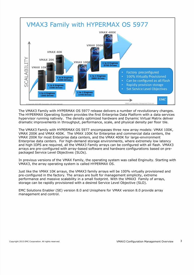
The VMAX3 Family with HYPERMAX OS 5977 release delivers a number of revolutionary changes.The HYPERMAX Operating System provides the first Enterprise Data Platform with a data serviceshypervisor running natively. The density optimized hardware and Dynamic Virtual Matrix deliverdramatic improvements in throughput, performance, scale, and physical density per floor tile.
The VMAX3 Family with HYPERMAX OS 5977 encompasses three new array models: VMAX 100K,VMAX 200K and VMAX 400K. The VMAX 100K for Enterprise and commercial data centers, theVMAX 200K for most Enterprise data centers, and the VMAX 400K for large-environmentEnterprise data centers. For high-demand storage environments, where extremely low latency
and high IOPS are required, all the VMAX3 Family arrays can be configured with all flash. VMAX3arrays are pre-configured with array-based software and hardware configurations based on pre-packaged Service Level Objectives (SLOs).
In previous versions of the VMAX Family, the operating system was called Enginuity. Starting withVMAX3, the array operating system is called HYPERMAX OS.
Just like the VMAX 10K arrays, the VMAX3 family arrays will be 100% virtually provisioned andpre-configured in the factory. The arrays are built for management simplicity, extremeperformance and massive scalability in a small footprint. With the VMAX3 Family of arrays,storage can be rapidly provisioned with a desired Service Level Objective (SLO).
EMC Solutions Enabler (SE) version 8.0 and Unisphere for VMAX version 8.0 provide arraymanagement and control.
VMAX3 Configuration Management Overview
7/18/2019 VMAX3 Configuration Management Overview
http://slidepdf.com/reader/full/vmax3-configuration-management-overview 4/40
4Copyright 2015 EMC Corporation. All rights reserved.
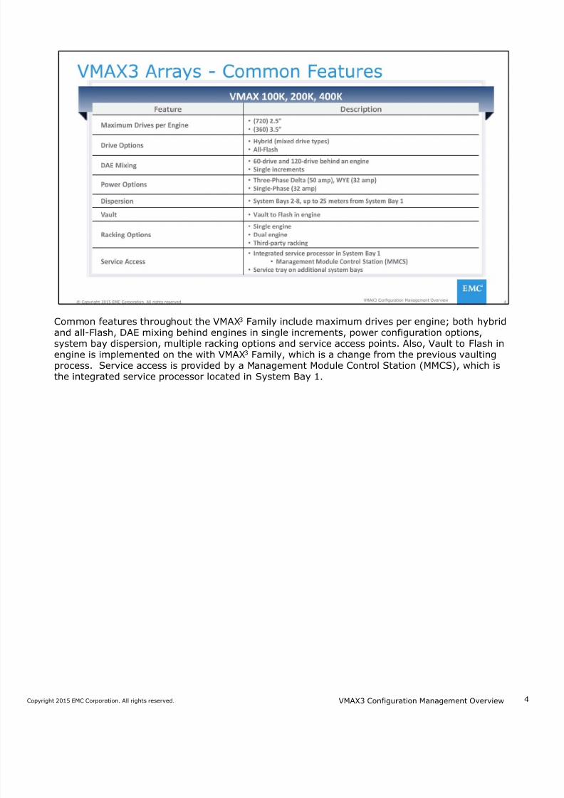
Common features throughout the VMAX3 Family include maximum drives per engine; both hybridand all-Flash, DAE mixing behind engines in single increments, power configuration options,system bay dispersion, multiple racking options and service access points. Also, Vault to Flash inengine is implemented on the with VMAX3 Family, which is a change from the previous vaultingprocess. Service access is provided by a Management Module Control Station (MMCS), which isthe integrated service processor located in System Bay 1.
VMAX3 Configuration Management Overview
7/18/2019 VMAX3 Configuration Management Overview
http://slidepdf.com/reader/full/vmax3-configuration-management-overview 5/40
5Copyright 2015 EMC Corporation. All rights reserved.
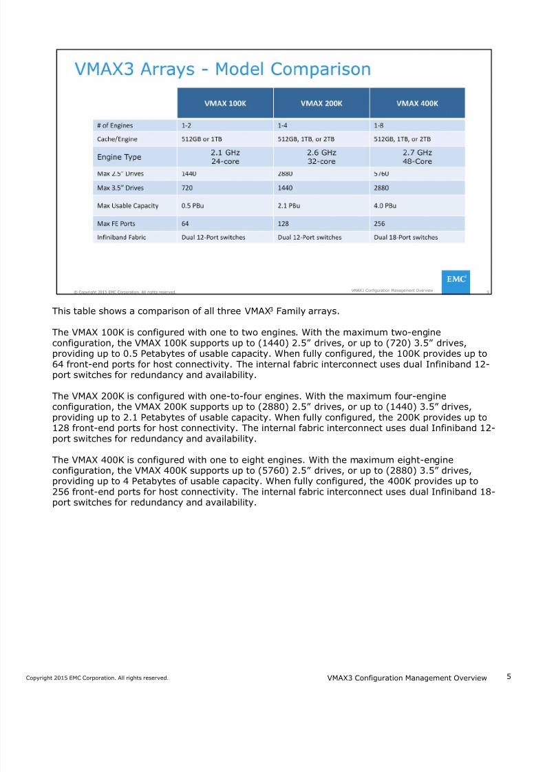
This table shows a comparison of all three VMAX3 Family arrays.
The VMAX 100K is configured with one to two engines. With the maximum two-engineconfiguration, the VMAX 100K supports up to (1440) 2.5” drives, or up to (720) 3.5” drives,providing up to 0.5 Petabytes of usable capacity. When fully configured, the 100K provides up to64 front-end ports for host connectivity. The internal fabric interconnect uses dual Infiniband 12-port switches for redundancy and availability.
The VMAX 200K is configured with one-to-four engines. With the maximum four-engine
configuration, the VMAX 200K supports up to (2880) 2.5” drives, or up to (1440) 3.5” drives,providing up to 2.1 Petabytes of usable capacity. When fully configured, the 200K provides up to128 front-end ports for host connectivity. The internal fabric interconnect uses dual Infiniband 12-port switches for redundancy and availability.
The VMAX 400K is configured with one to eight engines. With the maximum eight-engineconfiguration, the VMAX 400K supports up to (5760) 2.5” drives, or up to (2880) 3.5” drives,providing up to 4 Petabytes of usable capacity. When fully configured, the 400K provides up to256 front-end ports for host connectivity. The internal fabric interconnect uses dual Infiniband 18-port switches for redundancy and availability.
VMAX3 Configuration Management Overview
7/18/2019 VMAX3 Configuration Management Overview
http://slidepdf.com/reader/full/vmax3-configuration-management-overview 6/40
6Copyright 2015 EMC Corporation. All rights reserved.
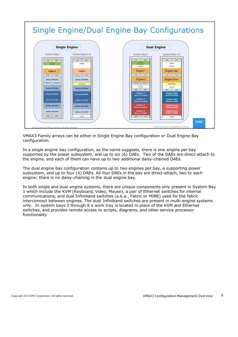
VMAX3 Family arrays can be either in Single Engine Bay configuration or Dual Engine Bayconfiguration.
In a single engine bay configuration, as the name suggests, there is one engine per baysupported by the power subsystem, and up to six (6) DAEs. Two of the DAEs are direct-attach tothe engine, and each of them can have up to two additional daisy-chained DAEs.
The dual engine bay configuration contains up to two engines per bay, a supporting powersubsystem, and up to four (4) DAEs. All four DAEs in the bay are direct-attach, two to each
engine; there is no daisy-chaining in the dual engine bay.
In both single and dual engine systems, there are unique components only present in System Bay1 which include the KVM (Keyboard, Video, Mouse), a pair of Ethernet switches for internalcommunications, and dual Infiniband switches (a.k.a., Fabric or MIBE) used for the fabricinterconnect between engines. The dual Infiniband switches are present in multi-engine systemsonly. In system bays 2 through 8 a work tray is located in place of the KVM and Ethernetswitches, and provides remote access to scripts, diagrams, and other service processorfunctionality
VMAX3 Configuration Management Overview
7/18/2019 VMAX3 Configuration Management Overview
http://slidepdf.com/reader/full/vmax3-configuration-management-overview 7/40
7Copyright 2015 EMC Corporation. All rights reserved.
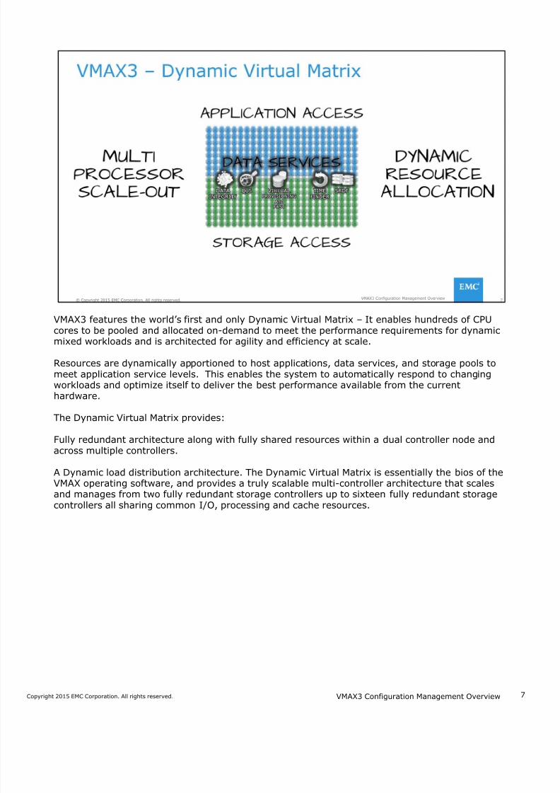
VMAX3 features the world’s first and only Dynamic Virtual Matrix – It enables hundreds of CPUcores to be pooled and allocated on-demand to meet the performance requirements for dynamicmixed workloads and is architected for agility and efficiency at scale.
Resources are dynamically apportioned to host applications, data services, and storage pools tomeet application service levels. This enables the system to automatically respond to changingworkloads and optimize itself to deliver the best performance available from the currenthardware.
The Dynamic Virtual Matrix provides:
Fully redundant architecture along with fully shared resources within a dual controller node andacross multiple controllers.
A Dynamic load distribution architecture. The Dynamic Virtual Matrix is essentially the bios of theVMAX operating software, and provides a truly scalable multi-controller architecture that scalesand manages from two fully redundant storage controllers up to sixteen fully redundant storagecontrollers all sharing common I/O, processing and cache resources.
VMAX3 Configuration Management Overview
7/18/2019 VMAX3 Configuration Management Overview
http://slidepdf.com/reader/full/vmax3-configuration-management-overview 8/40
8Copyright 2015 EMC Corporation. All rights reserved.
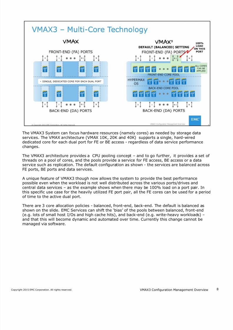
The VMAX3 System can focus hardware resources (namely cores) as needed by storage dataservices. The VMAX architecture (VMAX 10K, 20K and 40K) supports a single, hard-wireddedicated core for each dual port for FE or BE access - regardless of data service performancechanges.
The VMAX3 architecture provides a CPU pooling concept – and to go further, it provides a set ofthreads on a pool of cores, and the pools provide a service for FE access, BE access or a dataservice such as replication. The default configuration as shown - the services are balanced acrossFE ports, BE ports and data services.
A unique feature of VMAX3 though now allows the system to provide the best performancepossible even when the workload is not well distributed across the various ports/drives andcentral data services – as the example shows when there may be 100% load on a port pair. Inthis specific use case for the heavily utilized FE port pair, all the FE cores can be used for a periodof time to the active dual port.
There are 3 core allocation policies - balanced, front-end, back-end. The default is balanced asshown on the slide. EMC Services can shift the ‘bias’ of the pools between balanced, front-end(e.g. lots of small host I/Os and high cache hits), and back-end (e.g. write-heavy workloads) –and that this will become dynamic and automated over time. Currently this change cannot bemanaged via software.
VMAX3 Configuration Management Overview
7/18/2019 VMAX3 Configuration Management Overview
http://slidepdf.com/reader/full/vmax3-configuration-management-overview 9/40
9Copyright 2015 EMC Corporation. All rights reserved.
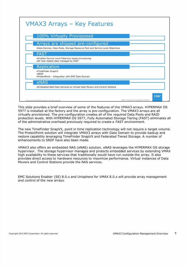
This slide provides a brief overview of some of the features of the VMAX3 arrays. HYPERMAX OS5977 is installed at the factory and the array is pre-configuration. The VMAX3 arrays are allvirtually provisioned. The pre-configuration creates all of the required Data Pools and RAIDprotection levels. With HYPERMAX OS 5977, Fully Automated Storage Tiering (FAST) eliminates allof the administrative overhead previously required to create a FAST environment.
The new TimeFinder SnapVX, point in time replication technology will not require a target volume.The ProtectPoint solution will integrate VMAX3 arrays with Data Domain to provide backup andrestore capability leveraging TimeFinder SnapVX and Federated Tiered Storage. A number of
enhancements to SRDF have also been made.
VMAX3 also offers an embedded NAS (eNAS) solution. eNAS leverages the HYPERMAX OS storagehypervisor. The storage hypervisor manages and protects embedded services by extending VMAXhigh availability to these services that traditionally would have run outside the array. It alsoprovides direct access to hardware resources to maximize performance. Virtual instances of DataMovers and Control Stations provide the NAS services.
EMC Solutions Enabler (SE) 8.0.x and Unisphere for VMAX 8.0.x will provide array managementand control of the new arrays.
VMAX3 Configuration Management Overview
7/18/2019 VMAX3 Configuration Management Overview
http://slidepdf.com/reader/full/vmax3-configuration-management-overview 10/40
1Copyright 2015 EMC Corporation. All rights reserved.
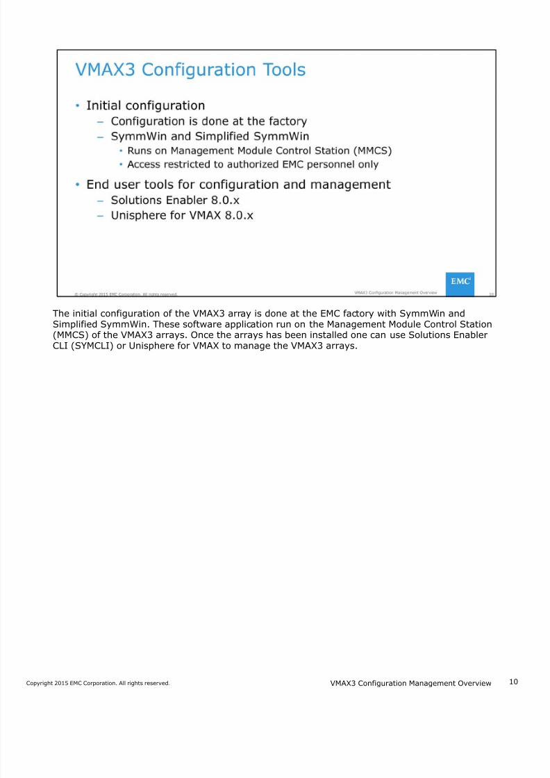
The initial configuration of the VMAX3 array is done at the EMC factory with SymmWin andSimplified SymmWin. These software application run on the Management Module Control Station(MMCS) of the VMAX3 arrays. Once the arrays has been installed one can use Solutions EnablerCLI (SYMCLI) or Unisphere for VMAX to manage the VMAX3 arrays.
VMAX3 Configuration Management Overview
7/18/2019 VMAX3 Configuration Management Overview
http://slidepdf.com/reader/full/vmax3-configuration-management-overview 11/40
1Copyright 2015 EMC Corporation. All rights reserved.
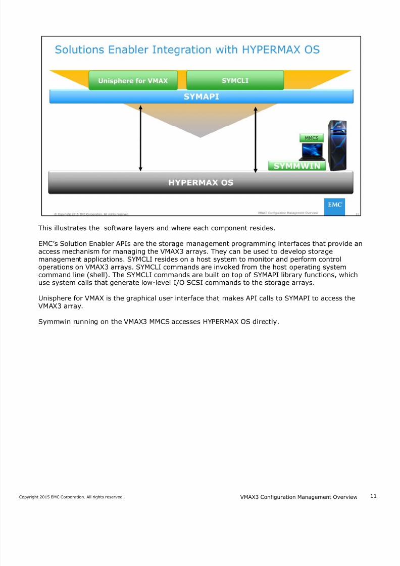
This illustrates the software layers and where each component resides.
EMC’s Solution Enabler APIs are the storage management programming interfaces that provide anaccess mechanism for managing the VMAX3 arrays. They can be used to develop storagemanagement applications. SYMCLI resides on a host system to monitor and perform controloperations on VMAX3 arrays. SYMCLI commands are invoked from the host operating systemcommand line (shell). The SYMCLI commands are built on top of SYMAPI library functions, whichuse system calls that generate low-level I/O SCSI commands to the storage arrays.
Unisphere for VMAX is the graphical user interface that makes API calls to SYMAPI to access theVMAX3 array.
Symmwin running on the VMAX3 MMCS accesses HYPERMAX OS directly.
VMAX3 Configuration Management Overview
7/18/2019 VMAX3 Configuration Management Overview
http://slidepdf.com/reader/full/vmax3-configuration-management-overview 12/40
1Copyright 2015 EMC Corporation. All rights reserved.
Solutions Enabler command line interface (SYMCLI) is used to perform control operations onVMAX arrays, and the array devices, tiers, groups, directors, and ports. Some of the VMAX3 arraycontrols include setting array-wide metrics, creating devices, and masking devices.
You can invoke SYMCLI from the local host to make configuration changes to a locally-connectedVMAX3 array or to an RDF-linked VMAX3 array.
VMAX3 Configuration Management Overview
7/18/2019 VMAX3 Configuration Management Overview
http://slidepdf.com/reader/full/vmax3-configuration-management-overview 13/40
1Copyright 2015 EMC Corporation. All rights reserved.
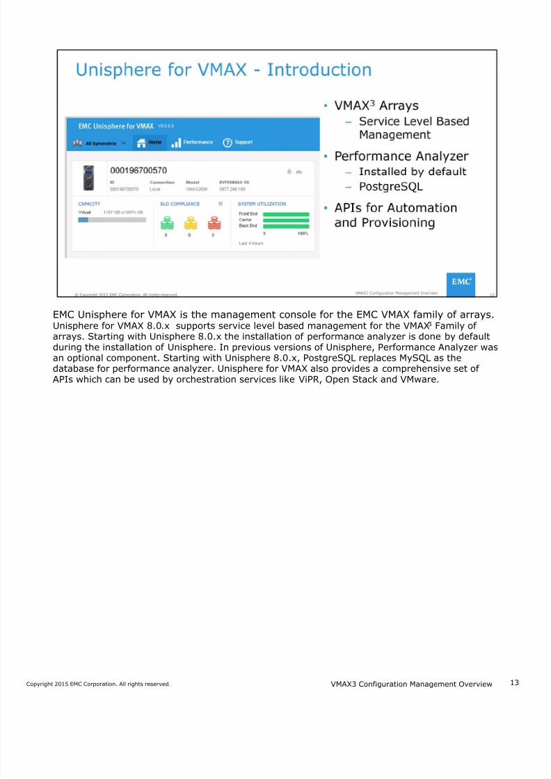
EMC Unisphere for VMAX is the management console for the EMC VMAX family of arrays.Unisphere for VMAX 8.0.x supports service level based management for the VMAX3 Family ofarrays. Starting with Unisphere 8.0.x the installation of performance analyzer is done by defaultduring the installation of Unisphere. In previous versions of Unisphere, Performance Analyzer wasan optional component. Starting with Unisphere 8.0.x, PostgreSQL replaces MySQL as thedatabase for performance analyzer. Unisphere for VMAX also provides a comprehensive set ofAPIs which can be used by orchestration services like ViPR, Open Stack and VMware.
VMAX3 Configuration Management Overview
7/18/2019 VMAX3 Configuration Management Overview
http://slidepdf.com/reader/full/vmax3-configuration-management-overview 14/40
14Copyright 2015 EMC Corporation. All rights reserved.
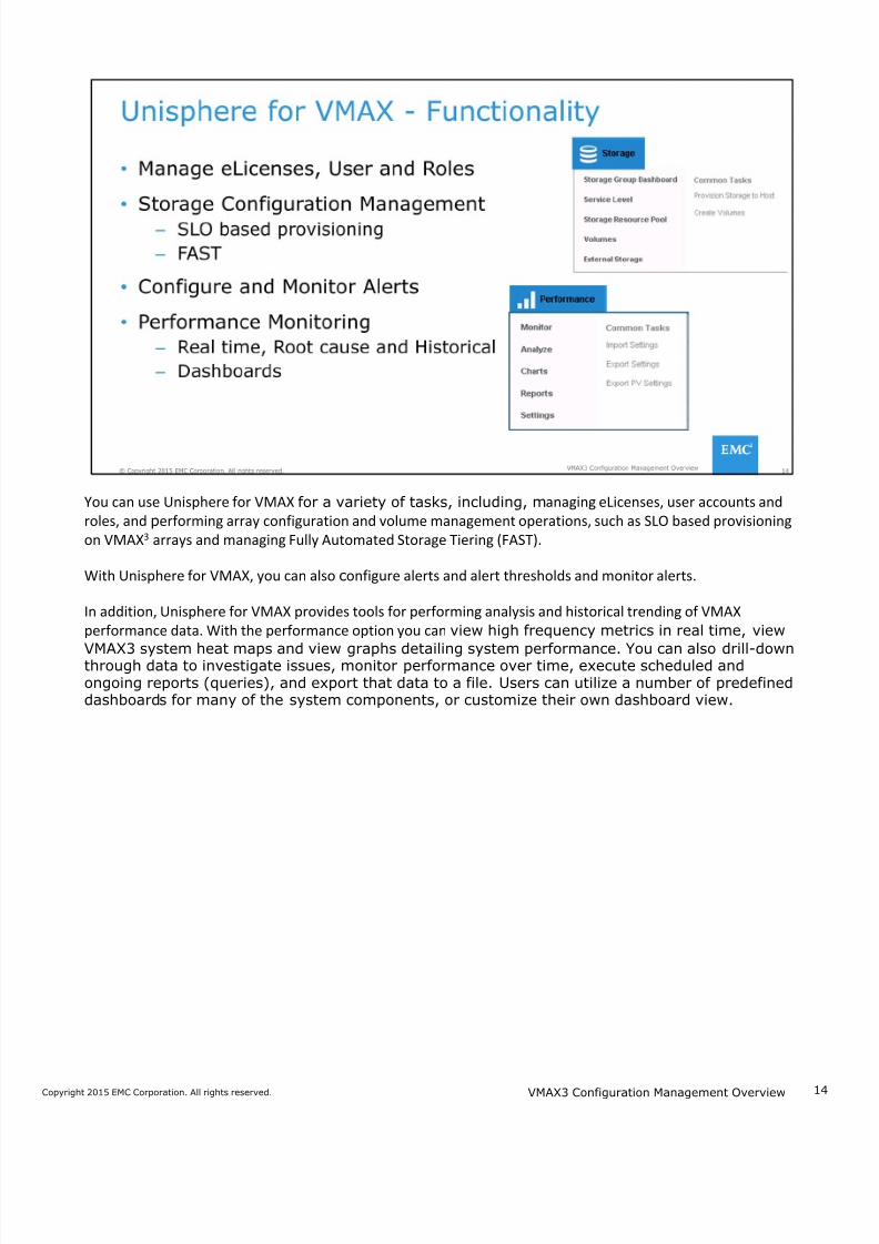
You can use Unisphere for VMAX for a variety of tasks, including, managing eLicenses, user accounts and
roles, and performing array configuration and volume management operations, such as SLO based provisioning
on VMAX3 arrays and managing Fully Automated Storage Tiering (FAST).
With Unisphere for VMAX, you can also configure alerts and alert thresholds and monitor alerts.
In addition, Unisphere for VMAX provides tools for performing analysis and historical trending of VMAX
performance data. With the performance option you can view high frequency metrics in real time, view
VMAX3 system heat maps and view graphs detailing system performance. You can also drill-downthrough data to investigate issues, monitor performance over time, execute scheduled andongoing reports (queries), and export that data to a file. Users can utilize a number of predefineddashboards for many of the system components, or customize their own dashboard view.
VMAX3 Configuration Management Overview
7/18/2019 VMAX3 Configuration Management Overview
http://slidepdf.com/reader/full/vmax3-configuration-management-overview 15/40
1Copyright 2015 EMC Corporation. All rights reserved.
This lesson provided an overview of the VMAX3 Family of arrays with HYPERMAX OS 5977. Wecompared the three models and listed the key features. Software tools used to manage VAMX3arrays were also introduced.
VMAX3 Configuration Management Overview
7/18/2019 VMAX3 Configuration Management Overview
http://slidepdf.com/reader/full/vmax3-configuration-management-overview 16/40
1Copyright 2015 EMC Corporation. All rights reserved.
This lesson covers factory pre-configuration of VMAX3 arrays and VMAX3 storage provisioningconcepts. An introduction to configuration changes with Unisphere for VMAX and SYMCLI is alsoprovided.
VMAX3 Configuration Management Overview
7/18/2019 VMAX3 Configuration Management Overview
http://slidepdf.com/reader/full/vmax3-configuration-management-overview 17/40
1Copyright 2015 EMC Corporation. All rights reserved.
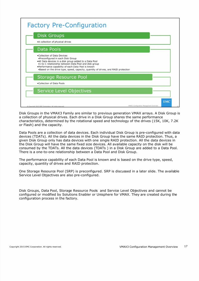
Disk Groups in the VMAX3 Family are similar to previous generation VMAX arrays. A Disk Group isa collection of physical drives. Each drive in a Disk Group shares the same performancecharacteristics, determined by the rotational speed and technology of the drives (15K, 10K, 7.2Kor Flash) and the capacity.
Data Pools are a collection of data devices. Each individual Disk Group is pre-configured with datadevices (TDATs). All the data devices in the Disk Group have the same RAID protection. Thus, agiven Disk Group only has data devices with one single RAID protection. All the data devices inthe Disk Group will have the same fixed size devices. All available capacity on the disk will be
consumed by the TDATs. All the data devices (TDATs ) in a Disk Group are added to a Data Pool.There is a one-to-one relationship between a Data Pool and Disk Group.
The performance capability of each Data Pool is known and is based on the drive type, speed,capacity, quantity of drives and RAID protection.
One Storage Resource Pool (SRP) is preconfigured. SRP is discussed in a later slide. The availableService Level Objectives are also pre-configured.
Disk Groups, Data Pool, Storage Resource Pools and Service Level Objectives and cannot beconfigured or modified by Solutions Enabler or Unisphere for VMAX. They are created during theconfiguration process in the factory.
VMAX3 Configuration Management Overview
7/18/2019 VMAX3 Configuration Management Overview
http://slidepdf.com/reader/full/vmax3-configuration-management-overview 18/40
1Copyright 2015 EMC Corporation. All rights reserved.
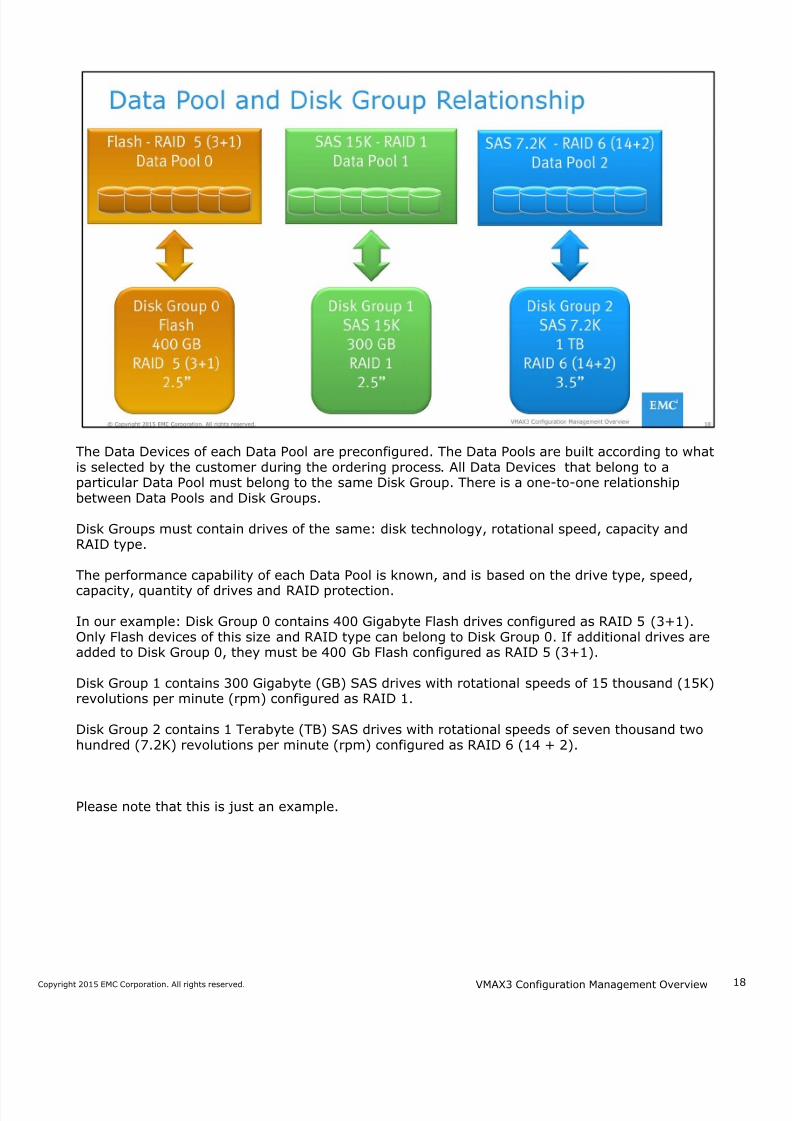
The Data Devices of each Data Pool are preconfigured. The Data Pools are built according to whatis selected by the customer during the ordering process. All Data Devices that belong to aparticular Data Pool must belong to the same Disk Group. There is a one-to-one relationshipbetween Data Pools and Disk Groups.
Disk Groups must contain drives of the same: disk technology, rotational speed, capacity andRAID type.
The performance capability of each Data Pool is known, and is based on the drive type, speed,
capacity, quantity of drives and RAID protection.
In our example: Disk Group 0 contains 400 Gigabyte Flash drives configured as RAID 5 (3+1).Only Flash devices of this size and RAID type can belong to Disk Group 0. If additional drives areadded to Disk Group 0, they must be 400 Gb Flash configured as RAID 5 (3+1).
Disk Group 1 contains 300 Gigabyte (GB) SAS drives with rotational speeds of 15 thousand (15K)revolutions per minute (rpm) configured as RAID 1.
Disk Group 2 contains 1 Terabyte (TB) SAS drives with rotational speeds of seven thousand twohundred (7.2K) revolutions per minute (rpm) configured as RAID 6 (14 + 2).
Please note that this is just an example.
VMAX3 Configuration Management Overview
7/18/2019 VMAX3 Configuration Management Overview
http://slidepdf.com/reader/full/vmax3-configuration-management-overview 19/40
1Copyright 2015 EMC Corporation. All rights reserved.
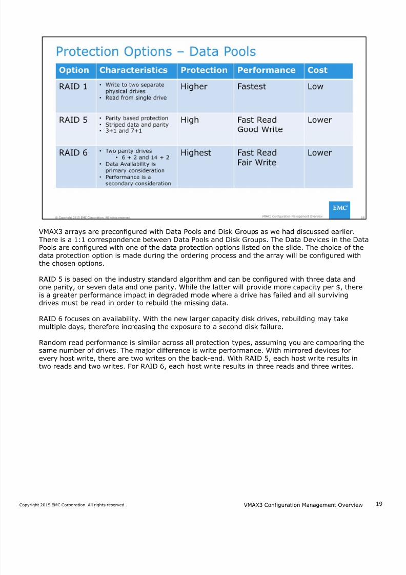
VMAX3 arrays are preconfigured with Data Pools and Disk Groups as we had discussed earlier.There is a 1:1 correspondence between Data Pools and Disk Groups. The Data Devices in the DataPools are configured with one of the data protection options listed on the slide. The choice of thedata protection option is made during the ordering process and the array will be configured withthe chosen options.
RAID 5 is based on the industry standard algorithm and can be configured with three data andone parity, or seven data and one parity. While the latter will provide more capacity per $, thereis a greater performance impact in degraded mode where a drive has failed and all surviving
drives must be read in order to rebuild the missing data.
RAID 6 focuses on availability. With the new larger capacity disk drives, rebuilding may takemultiple days, therefore increasing the exposure to a second disk failure.
Random read performance is similar across all protection types, assuming you are comparing thesame number of drives. The major difference is write performance. With mirrored devices forevery host write, there are two writes on the back-end. With RAID 5, each host write results intwo reads and two writes. For RAID 6, each host write results in three reads and three writes.
VMAX3 Configuration Management Overview
7/18/2019 VMAX3 Configuration Management Overview
http://slidepdf.com/reader/full/vmax3-configuration-management-overview 20/40
2Copyright 2015 EMC Corporation. All rights reserved.
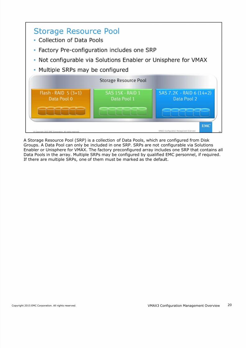
A Storage Resource Pool (SRP) is a collection of Data Pools, which are configured from DiskGroups. A Data Pool can only be included in one SRP. SRPs are not configurable via SolutionsEnabler or Unisphere for VMAX. The factory preconfigured array includes one SRP that contains allData Pools in the array. Multiple SRPs may be configured by qualified EMC personnel, if required.If there are multiple SRPs, one of them must be marked as the default.
VMAX3 Configuration Management Overview
7/18/2019 VMAX3 Configuration Management Overview
http://slidepdf.com/reader/full/vmax3-configuration-management-overview 21/40
2Copyright 2015 EMC Corporation. All rights reserved.
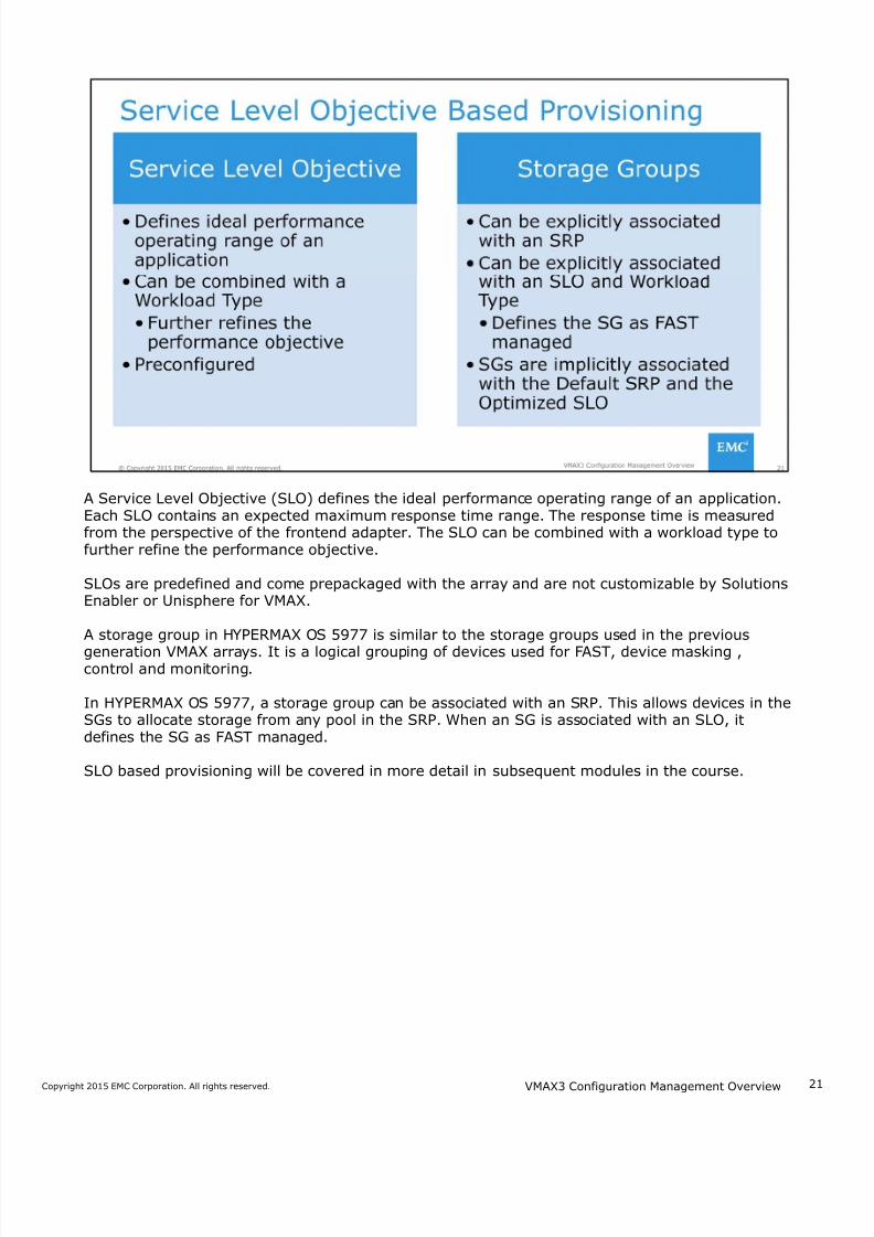
A Service Level Objective (SLO) defines the ideal performance operating range of an application.Each SLO contains an expected maximum response time range. The response time is measuredfrom the perspective of the frontend adapter. The SLO can be combined with a workload type tofurther refine the performance objective.
SLOs are predefined and come prepackaged with the array and are not customizable by SolutionsEnabler or Unisphere for VMAX.
A storage group in HYPERMAX OS 5977 is similar to the storage groups used in the previous
generation VMAX arrays. It is a logical grouping of devices used for FAST, device masking ,control and monitoring.
In HYPERMAX OS 5977, a storage group can be associated with an SRP. This allows devices in theSGs to allocate storage from any pool in the SRP. When an SG is associated with an SLO, itdefines the SG as FAST managed.
SLO based provisioning will be covered in more detail in subsequent modules in the course.
VMAX3 Configuration Management Overview
7/18/2019 VMAX3 Configuration Management Overview
http://slidepdf.com/reader/full/vmax3-configuration-management-overview 22/40
2Copyright 2015 EMC Corporation. All rights reserved.
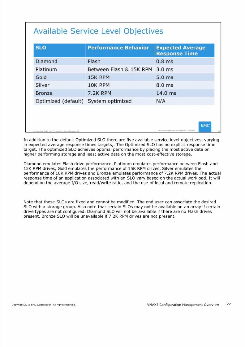
In addition to the default Optimized SLO there are five available service level objectives, varyingin expected average response times targets,. The Optimized SLO has no explicit response timetarget. The optimized SLO achieves optimal performance by placing the most active data onhigher performing storage and least active data on the most cost-effective storage.
Diamond emulates Flash drive performance, Platinum emulates performance between Flash and15K RPM drives, Gold emulates the performance of 15K RPM drives, Silver emulates theperformance of 10K RPM drives and Bronze emulates performance of 7.2K RPM drives. The actualresponse time of an application associated with an SLO vary based on the actual workload. It will
depend on the average I/O size, read/write ratio, and the use of local and remote replication.
Note that these SLOs are fixed and cannot be modified. The end user can associate the desiredSLO with a storage group. Also note that certain SLOs may not be available on an array if certaindrive types are not configured. Diamond SLO will not be available if there are no Flash drivespresent. Bronze SLO will be unavailable if 7.2K RPM drives are not present.
VMAX3 Configuration Management Overview
7/18/2019 VMAX3 Configuration Management Overview
http://slidepdf.com/reader/full/vmax3-configuration-management-overview 23/40
2Copyright 2015 EMC Corporation. All rights reserved.
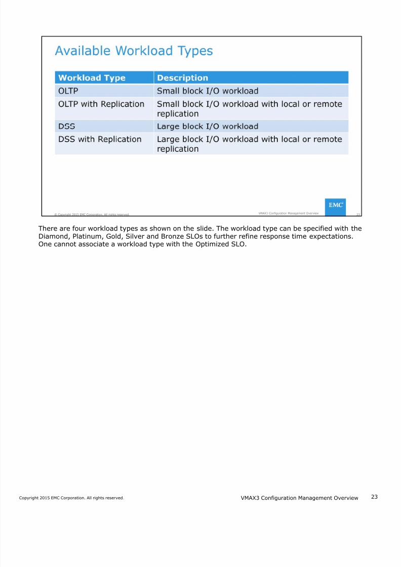
There are four workload types as shown on the slide. The workload type can be specified with theDiamond, Platinum, Gold, Silver and Bronze SLOs to further refine response time expectations.One cannot associate a workload type with the Optimized SLO.
VMAX3 Configuration Management Overview
7/18/2019 VMAX3 Configuration Management Overview
http://slidepdf.com/reader/full/vmax3-configuration-management-overview 24/40
24Copyright 2015 EMC Corporation. All rights reserved.
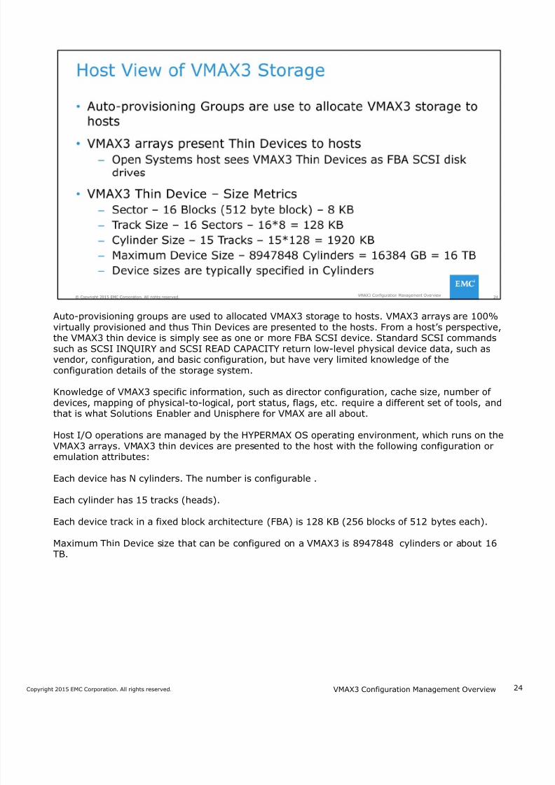
Auto-provisioning groups are used to allocated VMAX3 storage to hosts. VMAX3 arrays are 100%virtually provisioned and thus Thin Devices are presented to the hosts. From a host’s perspective,the VMAX3 thin device is simply see as one or more FBA SCSI device. Standard SCSI commandssuch as SCSI INQUIRY and SCSI READ CAPACITY return low-level physical device data, such asvendor, configuration, and basic configuration, but have very limited knowledge of theconfiguration details of the storage system.
Knowledge of VMAX3 specific information, such as director configuration, cache size, number ofdevices, mapping of physical-to-logical, port status, flags, etc. require a different set of tools, and
that is what Solutions Enabler and Unisphere for VMAX are all about.
Host I/O operations are managed by the HYPERMAX OS operating environment, which runs on theVMAX3 arrays. VMAX3 thin devices are presented to the host with the following configuration oremulation attributes:
Each device has N cylinders. The number is configurable .
Each cylinder has 15 tracks (heads).
Each device track in a fixed block architecture (FBA) is 128 KB (256 blocks of 512 bytes each).
Maximum Thin Device size that can be configured on a VMAX3 is 8947848 cylinders or about 16TB.
VMAX3 Configuration Management Overview
7/18/2019 VMAX3 Configuration Management Overview
http://slidepdf.com/reader/full/vmax3-configuration-management-overview 25/40
2Copyright 2015 EMC Corporation. All rights reserved.
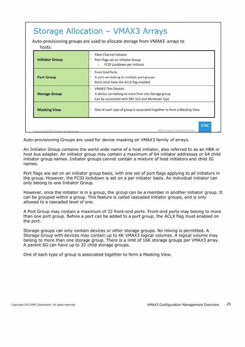
Auto-provisioning Groups are used for device masking on VMAX3 family of arrays.
An Initiator Group contains the world wide name of a host initiator, also referred to as an HBA orhost bus adapter. An initiator group may contain a maximum of 64 initiator addresses or 64 childinitiator group names. Initiator groups cannot contain a mixture of host initiators and child IGnames.
Port flags are set on an initiator group basis, with one set of port flags applying to all initiators inthe group. However, the FCID lockdown is set on a per initiator basis. An individual initiator can
only belong to one Initiator Group.
However, once the initiator is in a group, the group can be a member in another initiator group. Itcan be grouped within a group. This feature is called cascaded initiator groups, and is onlyallowed to a cascaded level of one.
A Port Group may contain a maximum of 32 front-end ports. Front-end ports may belong to morethan one port group. Before a port can be added to a port group, the ACLX flag must enabled onthe port.
Storage groups can only contain devices or other storage groups. No mixing is permitted. AStorage Group with devices may contain up to 4K VMAX3 logical volumes. A logical volume maybelong to more than one storage group. There is a limit of 16K storage groups per VMAX3 array.A parent SG can have up to 32 child storage groups.
One of each type of group is associated together to form a Masking View.
VMAX3 Configuration Management Overview
7/18/2019 VMAX3 Configuration Management Overview
http://slidepdf.com/reader/full/vmax3-configuration-management-overview 26/40
2Copyright 2015 EMC Corporation. All rights reserved.
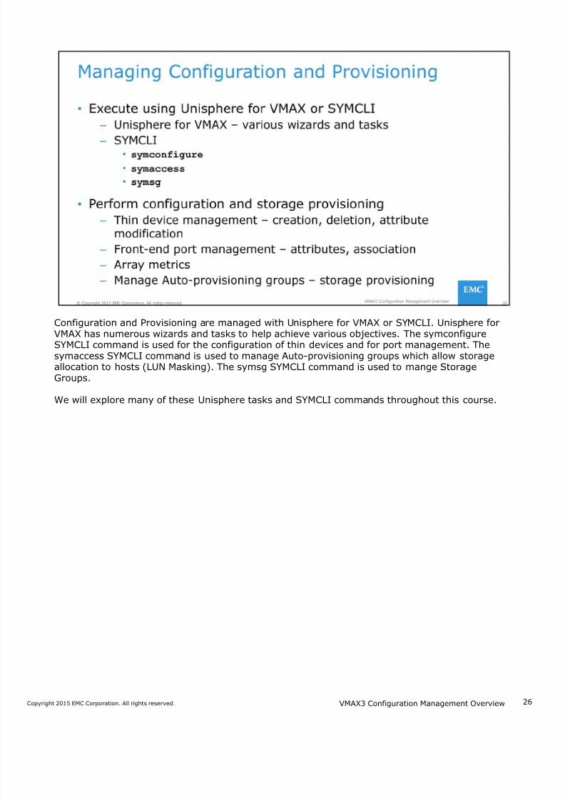
Configuration and Provisioning are managed with Unisphere for VMAX or SYMCLI. Unisphere forVMAX has numerous wizards and tasks to help achieve various objectives. The symconfigureSYMCLI command is used for the configuration of thin devices and for port management. Thesymaccess SYMCLI command is used to manage Auto-provisioning groups which allow storageallocation to hosts (LUN Masking). The symsg SYMCLI command is used to mange StorageGroups.
We will explore many of these Unisphere tasks and SYMCLI commands throughout this course.
VMAX3 Configuration Management Overview
7/18/2019 VMAX3 Configuration Management Overview
http://slidepdf.com/reader/full/vmax3-configuration-management-overview 27/40
2Copyright 2015 EMC Corporation. All rights reserved.
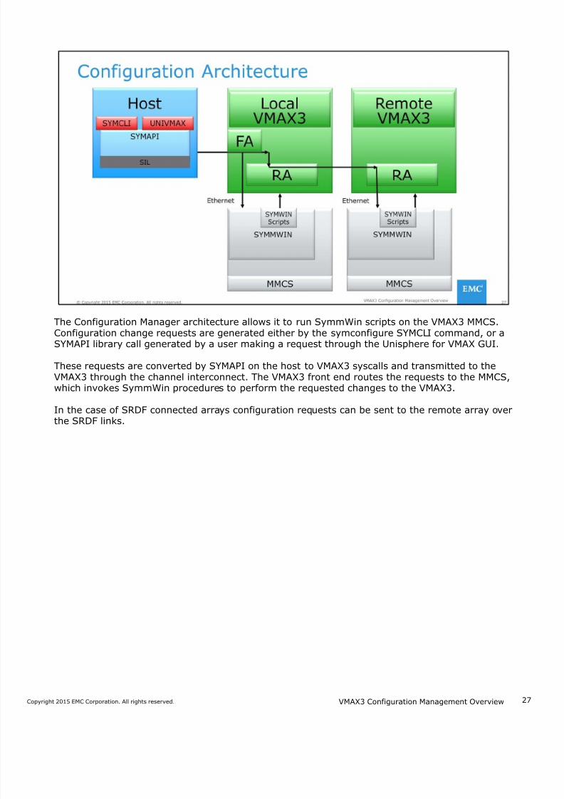
The Configuration Manager architecture allows it to run SymmWin scripts on the VMAX3 MMCS.Configuration change requests are generated either by the symconfigure SYMCLI command, or aSYMAPI library call generated by a user making a request through the Unisphere for VMAX GUI.
These requests are converted by SYMAPI on the host to VMAX3 syscalls and transmitted to theVMAX3 through the channel interconnect. The VMAX3 front end routes the requests to the MMCS,which invokes SymmWin procedures to perform the requested changes to the VMAX3.
In the case of SRDF connected arrays configuration requests can be sent to the remote array over
the SRDF links.
VMAX3 Configuration Management Overview
7/18/2019 VMAX3 Configuration Management Overview
http://slidepdf.com/reader/full/vmax3-configuration-management-overview 28/40
2Copyright 2015 EMC Corporation. All rights reserved.
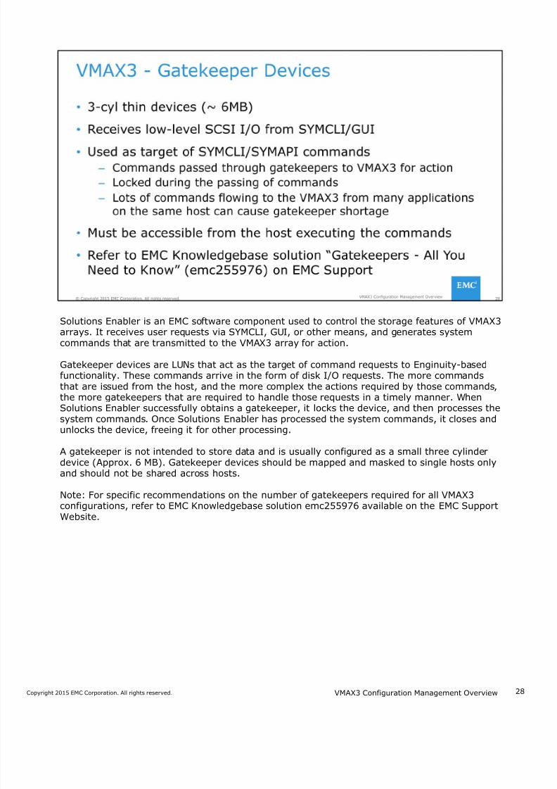
Solutions Enabler is an EMC software component used to control the storage features of VMAX3arrays. It receives user requests via SYMCLI, GUI, or other means, and generates systemcommands that are transmitted to the VMAX3 array for action.
Gatekeeper devices are LUNs that act as the target of command requests to Enginuity-basedfunctionality. These commands arrive in the form of disk I/O requests. The more commandsthat are issued from the host, and the more complex the actions required by those commands,the more gatekeepers that are required to handle those requests in a timely manner. WhenSolutions Enabler successfully obtains a gatekeeper, it locks the device, and then processes thesystem commands. Once Solutions Enabler has processed the system commands, it closes andunlocks the device, freeing it for other processing.
A gatekeeper is not intended to store data and is usually configured as a small three cylinderdevice (Approx. 6 MB). Gatekeeper devices should be mapped and masked to single hosts onlyand should not be shared across hosts.
Note: For specific recommendations on the number of gatekeepers required for all VMAX3configurations, refer to EMC Knowledgebase solution emc255976 available on the EMC SupportWebsite.
VMAX3 Configuration Management Overview
7/18/2019 VMAX3 Configuration Management Overview
http://slidepdf.com/reader/full/vmax3-configuration-management-overview 29/40
2Copyright 2015 EMC Corporation. All rights reserved.
VMAX3 arrays allow, up to four concurrent configuration change sessions to run at the same time,when they are non-conflicting. This means that multiple parallel configuration change sessionscan run at the same time as long as the changes do not include any conflicts on the following:
• Device back-end port
• Device front-end port
• Device
The array manages its own device locking and each running session is identified by a session ID.
VMAX3 Configuration Management Overview
7/18/2019 VMAX3 Configuration Management Overview
http://slidepdf.com/reader/full/vmax3-configuration-management-overview 30/40
3Copyright 2015 EMC Corporation. All rights reserved.
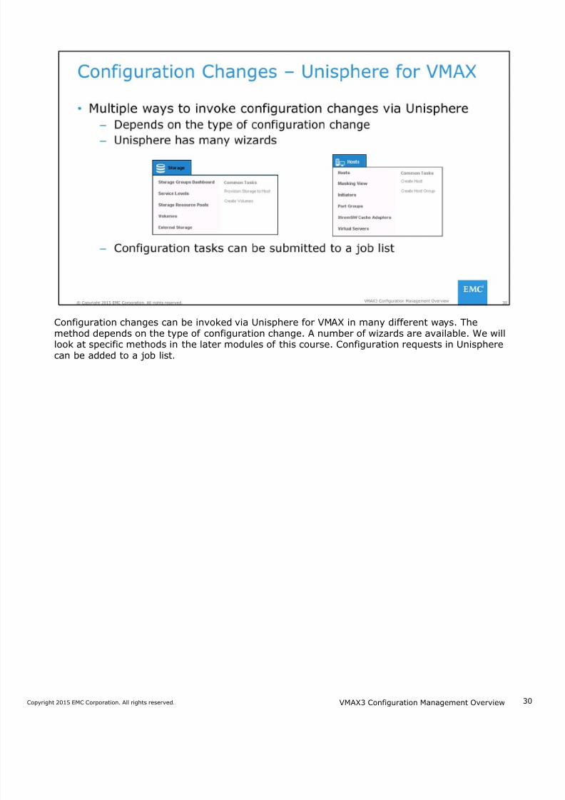
Configuration changes can be invoked via Unisphere for VMAX in many different ways. Themethod depends on the type of configuration change. A number of wizards are available. We willlook at specific methods in the later modules of this course. Configuration requests in Unispherecan be added to a job list.
VMAX3 Configuration Management Overview
7/18/2019 VMAX3 Configuration Management Overview
http://slidepdf.com/reader/full/vmax3-configuration-management-overview 31/40
3Copyright 2015 EMC Corporation. All rights reserved.
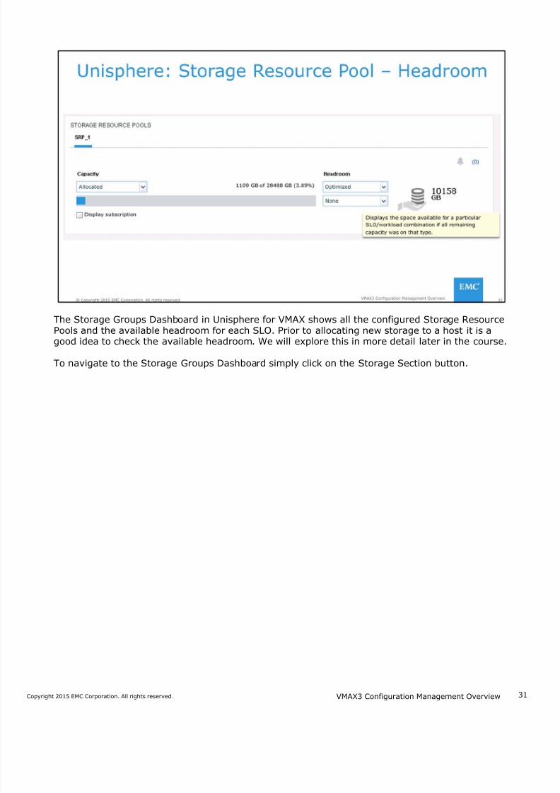
The Storage Groups Dashboard in Unisphere for VMAX shows all the configured Storage ResourcePools and the available headroom for each SLO. Prior to allocating new storage to a host it is agood idea to check the available headroom. We will explore this in more detail later in the course.
To navigate to the Storage Groups Dashboard simply click on the Storage Section button.
VMAX3 Configuration Management Overview
7/18/2019 VMAX3 Configuration Management Overview
http://slidepdf.com/reader/full/vmax3-configuration-management-overview 32/40
3Copyright 2015 EMC Corporation. All rights reserved.
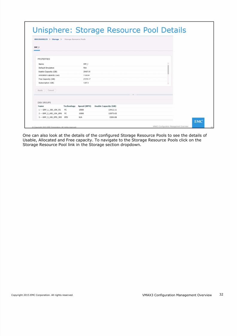
One can also look at the details of the configured Storage Resource Pools to see the details ofUsable, Allocated and Free capacity. To navigate to the Storage Resource Pools click on theStorage Resource Pool link in the Storage section dropdown.
VMAX3 Configuration Management Overview
7/18/2019 VMAX3 Configuration Management Overview
http://slidepdf.com/reader/full/vmax3-configuration-management-overview 33/40
3Copyright 2015 EMC Corporation. All rights reserved.
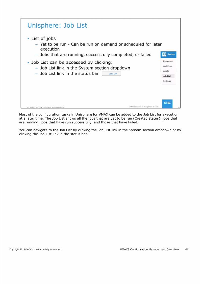
Most of the configuration tasks in Unisphere for VMAX can be added to the Job List for executionat a later time. The Job List shows all the jobs that are yet to be run (Created status), jobs thatare running, jobs that have run successfully, and those that have failed.
You can navigate to the Job List by clicking the Job List link in the System section dropdown or byclicking the Job List link in the status bar.
VMAX3 Configuration Management Overview
7/18/2019 VMAX3 Configuration Management Overview
http://slidepdf.com/reader/full/vmax3-configuration-management-overview 34/40
34Copyright 2015 EMC Corporation. All rights reserved.
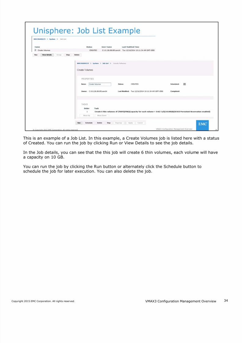
This is an example of a Job List. In this example, a Create Volumes job is listed here with a statusof Created. You can run the job by clicking Run or View Details to see the job details.
In the Job details, you can see that the this job will create 6 thin volumes, each volume will havea capacity on 10 GB.
You can run the job by clicking the Run button or alternately click the Schedule button toschedule the job for later execution. You can also delete the job.
VMAX3 Configuration Management Overview
7/18/2019 VMAX3 Configuration Management Overview
http://slidepdf.com/reader/full/vmax3-configuration-management-overview 35/40
3Copyright 2015 EMC Corporation. All rights reserved.
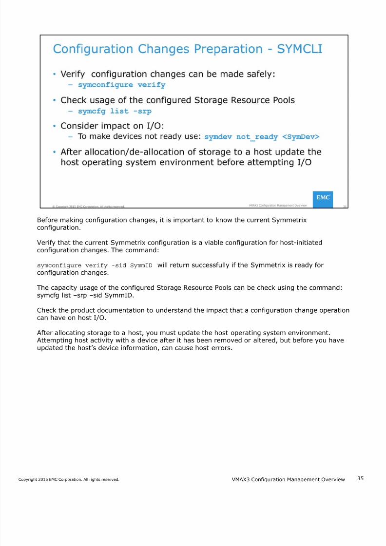
Before making configuration changes, it is important to know the current Symmetrixconfiguration.
Verify that the current Symmetrix configuration is a viable configuration for host-initiatedconfiguration changes. The command:
symconfigure verify -sid SymmID will return successfully if the Symmetrix is ready forconfiguration changes.
The capacity usage of the configured Storage Resource Pools can be check using the command:symcfg list –srp –sid SymmID.
Check the product documentation to understand the impact that a configuration change operationcan have on host I/O.
After allocating storage to a host, you must update the host operating system environment.Attempting host activity with a device after it has been removed or altered, but before you haveupdated the host’s device information, can cause host errors.
VMAX3 Configuration Management Overview
7/18/2019 VMAX3 Configuration Management Overview
http://slidepdf.com/reader/full/vmax3-configuration-management-overview 36/40
3Copyright 2015 EMC Corporation. All rights reserved.
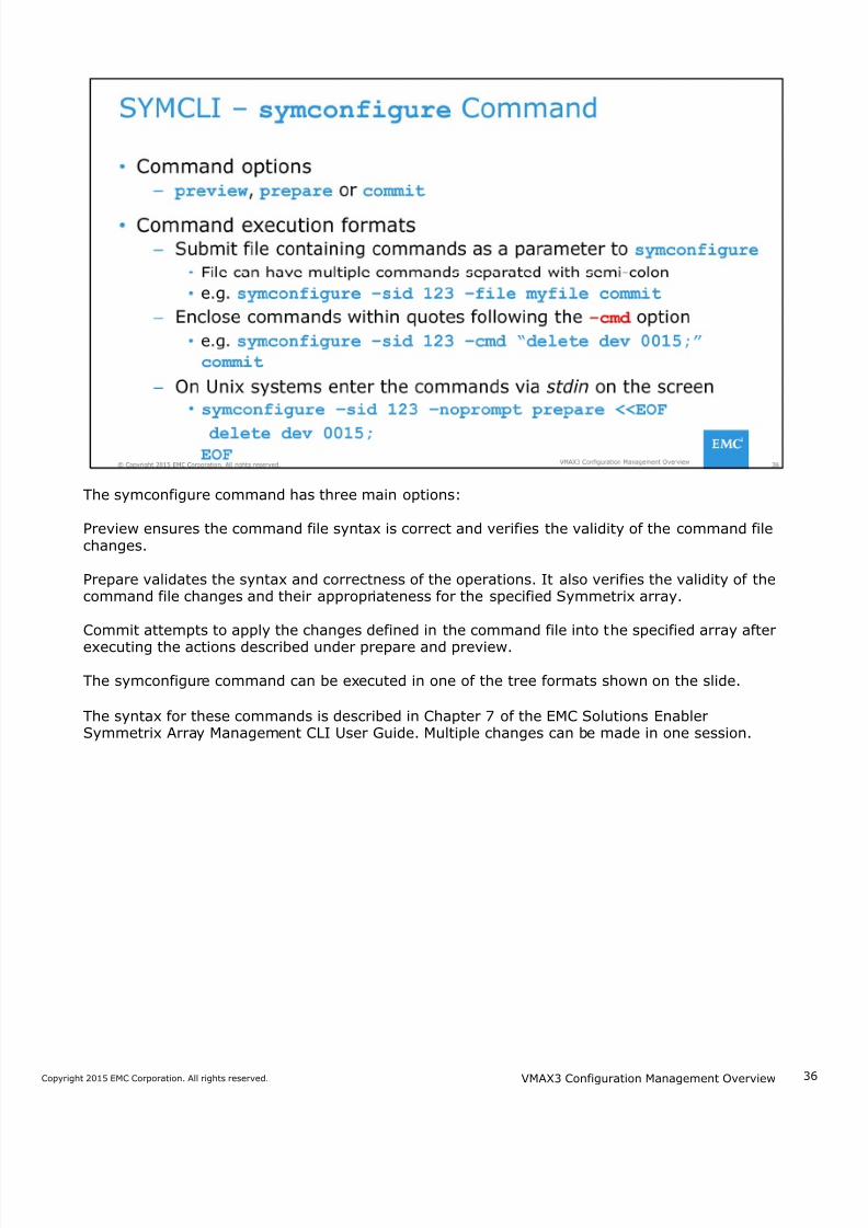
The symconfigure command has three main options:
Preview ensures the command file syntax is correct and verifies the validity of the command filechanges.
Prepare validates the syntax and correctness of the operations. It also verifies the validity of thecommand file changes and their appropriateness for the specified Symmetrix array.
Commit attempts to apply the changes defined in the command file into the specified array after
executing the actions described under prepare and preview.
The symconfigure command can be executed in one of the tree formats shown on the slide.
The syntax for these commands is described in Chapter 7 of the EMC Solutions EnablerSymmetrix Array Management CLI User Guide. Multiple changes can be made in one session.
VMAX3 Configuration Management Overview
7/18/2019 VMAX3 Configuration Management Overview
http://slidepdf.com/reader/full/vmax3-configuration-management-overview 37/40
3Copyright 2015 EMC Corporation. All rights reserved.
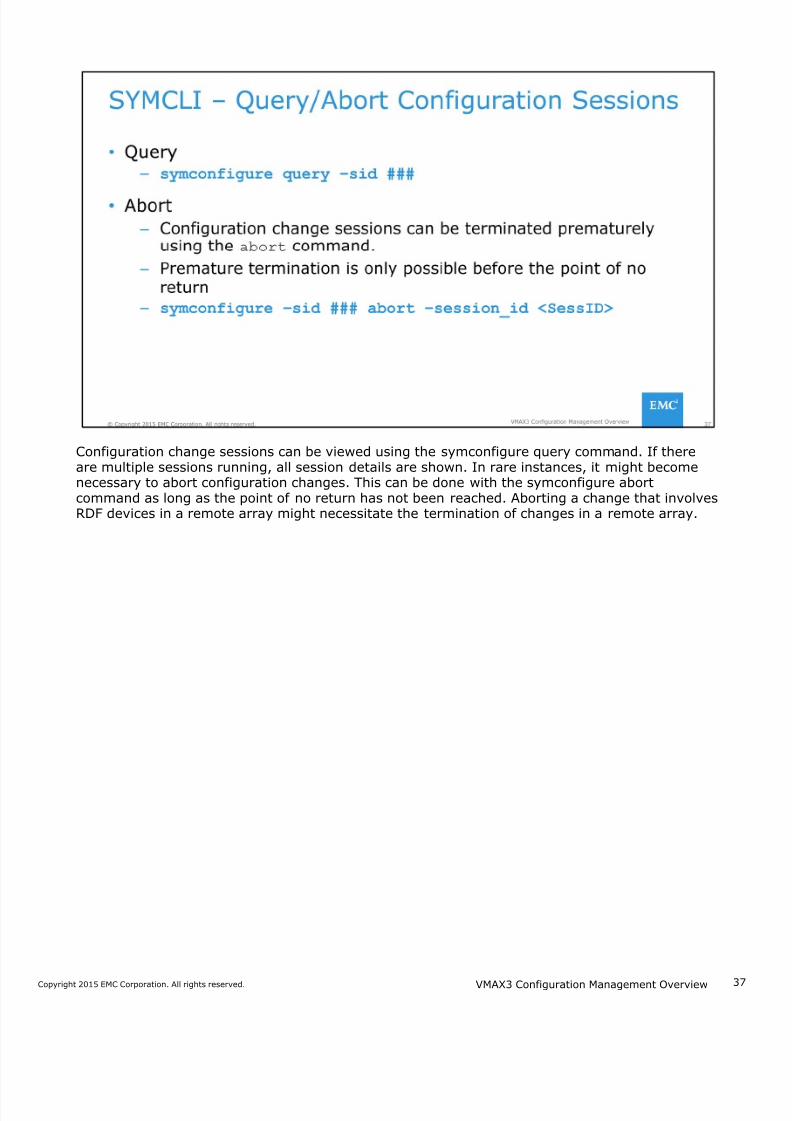
Configuration change sessions can be viewed using the symconfigure query command. If thereare multiple sessions running, all session details are shown. In rare instances, it might becomenecessary to abort configuration changes. This can be done with the symconfigure abortcommand as long as the point of no return has not been reached. Aborting a change that involvesRDF devices in a remote array might necessitate the termination of changes in a remote array.
VMAX3 Configuration Management Overview
7/18/2019 VMAX3 Configuration Management Overview
http://slidepdf.com/reader/full/vmax3-configuration-management-overview 38/40
3Copyright 2015 EMC Corporation. All rights reserved.
This lesson covered factory pre-configuration of VMAX3 arrays and VMAX3 storage provisioningconcepts. An introduction to configuration changes with Unisphere for VMAX and SYMCLI was alsoprovided.
VMAX3 Configuration Management Overview
7/18/2019 VMAX3 Configuration Management Overview
http://slidepdf.com/reader/full/vmax3-configuration-management-overview 39/40
3Copyright 2015 EMC Corporation. All rights reserved.
In this Lab you will explore a VMAX3 environment with Unisphere for VMAX and SYMCLI.
VMAX3 Configuration Management Overview
7/18/2019 VMAX3 Configuration Management Overview
http://slidepdf.com/reader/full/vmax3-configuration-management-overview 40/40
This module covered an overview of the VMAX3 Family of arrays with HYPERMAX OS 5977. Keyfeatures and storage provisioning concepts were covered. The CLI command structure forconfiguration, and how to perform configuration changes with Unisphere for VMAX were alsodescribed.