Embed Size (px)
DESCRIPTION
vmax datastore
Citation preview
Document Type EIS Local Instruction (LIN)
Document Title EMC V-Max Blade SAN array Virtual LUN creation and standards Document Identifier Version Effective Date Review Date Page No
Blade_SAN_LIN_19520 01 19-Nov-2010 19-Nov-2012 1 of 40
EIS Local Instruction Template – ITI_SOP_001T03_07
UNCONTROLLED COPY WHEN PRINTED. FOR INFORMATION ONLY Company Confidential
Approval Completion of the following signature blocks signifies the review and approval of this EIS Local Instruction.
Name Job Title or Role Signature Date (dd-mmm-yyyy)
The Author is signing to confirm that this document has been prepared in accordance with ITI_SOP_001.
Authored by: David B. Beeker
Sr. Consultant Storage Engineering
Signature on file Date on file
The Q&C Approver is signing to confirm that this document has been completed in accordance with ITI_SOP_001 and that it meets Quality & Regulatory Requirements.
Quality & Compliance Approval by: Aneta Glowacka
EIS Q&C Consultant
Signature on file Date on file
The Management Approver is signing to confirm that he/she understands the content of this Local Instruction, confirms that all necessary testing of this Local Instruction has been conducted with successful outcome, and that he/she approves this Local Instruction for operational use.
Management Approval by Head of EIS Department: Roy Hall
Director EST Storage
Engineering
Signature on file Date on file
Management Approval by: Kevin Shimmin
EST Change & Configuration Manager
Signature on file Date on file
The Service Management Approver is signing to confirm that he/she understands the content of this Local Instruction, confirms that all necessary testing of this Local Instruction has been conducted with successful outcome, and that he/she approves this Local Instruction for operational use.
Service Management Approval: Mark Walsh
Technical Services Manager
(GSK)
Signature on file Date on file
This document is owned by Director EST Storage Engineering
Document Type EIS Local Instruction (LIN)
Document Title EMC V-Max Blade SAN array Virtual LUN creation and standards Document Identifier Version Effective Date Review Date Page No
Blade_SAN_LIN_19520 01 19-Nov-2010 19-Nov-2012 2 of 40
EIS Local Instruction Template – ITI_SOP_001T03_07
UNCONTROLLED COPY WHEN PRINTED. FOR INFORMATION ONLY Company Confidential
Table of Contents 1. Purpose .............................................................................................................. 3 2. Scope ................................................................................................................. 3 3. Intended Audience ............................................................................................ 3 4. Roles and Responsibilities ............................................................................... 3 5. Process Map ...................................................................................................... 4 6. Inputs / Entrance Criteria .................................................................................. 4 7. Instructional Steps ............................................................................................ 4 7.1. Risk/Impact ......................................................................................................... 4 7.2. Instructions .......................................................................................................... 5 7.2.1. Zoning .................................................................................................................... 5 7.2.2. Create Virtual Pool Data Devices ........................................................................... 7 7.2.3. Create New Virtual Pool ....................................................................................... 10 7.2.4. Add Datadevs to Pool .......................................................................................... 11 7.2.5. Create a Thin Volume .......................................................................................... 13 7.2.6. Form a Thin Meta Volume .................................................................................... 14 7.2.7. Bind a Thin Volume to the Pool ............................................................................ 16 7.2.8. Complete Auto Provisioning ................................................................................. 19 7.2.9. ESX datastore creation ........................................................................................ 28 7.3. Post Execution Verification................................................................................ 30 7.4. Back-out Instructions ......................................................................................... 31 7.4.1. Delete Datastore from ESX host .......................................................................... 31 7.4.2. Delete Masking View and Auto-Provisioned Groups ............................................ 31 7.4.3. Unbind and Delete Thin Device ............................................................................ 36
8. Training Requirements ................................................................................... 38 9. Glossary ........................................................................................................... 38 10. References ....................................................................................................... 38 11. Revision Details .............................................................................................. 39 Appendix A. VMFS Disk Volume Naming .......................................................................... 40
Document Type EIS Local Instruction (LIN)
Document Title EMC V-Max Blade SAN array Virtual LUN creation and standards Document Identifier Version Effective Date Review Date Page No
Blade_SAN_LIN_19520 01 19-Nov-2010 19-Nov-2012 3 of 40
EIS Local Instruction Template – ITI_SOP_001T03_07
UNCONTROLLED COPY WHEN PRINTED. FOR INFORMATION ONLY Company Confidential
1. Purpose This set of instructions will be used for establishing storage pools and LUN presentations needed for the Blade SAN environment using Vmware, Windows, and Linux. Note: Red text in this document represents a section or information that is important and the reader must pay attention too.
2. Scope This LIN is to be used by all Operations staff responsible for managing and maintaining SAN storage on EMC storage arrays and should be used only in the Blade SAN environment.
3. Intended Audience Service Groups/Services who will use this procedure.
Storage Operations
4. Roles and Responsibilities Role Summary of Responsibilities Storage Operations
Create and maintain Storage Pools, Thin devices, Meta Devices, Storage Groups, Initiator Groups, Port Groups, Masking View, ESX datastores for Blade SAN storage array connectivity.
Document Type EIS Local Instruction (LIN)
Document Title EMC V-Max Blade SAN array Virtual LUN creation and standards Document Identifier Version Effective Date Review Date Page No
Blade_SAN_LIN_19520 01 19-Nov-2010 19-Nov-2012 4 of 40
EIS Local Instruction Template – ITI_SOP_001T03_07
UNCONTROLLED COPY WHEN PRINTED. FOR INFORMATION ONLY Company Confidential
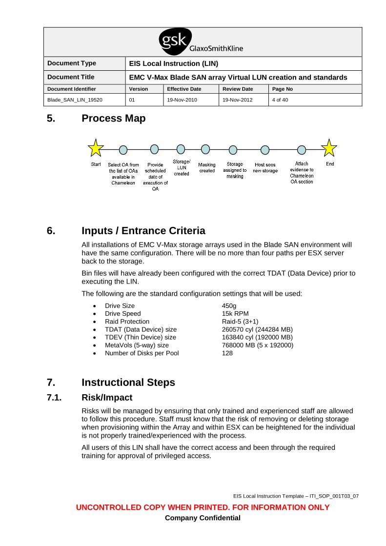
5. Process Map
6. Inputs / Entrance Criteria All installations of EMC V-Max storage arrays used in the Blade SAN environment will have the same configuration. There will be no more than four paths per ESX server back to the storage.
Bin files will have already been configured with the correct TDAT (Data Device) prior to executing the LIN.
The following are the standard configuration settings that will be used:
• Drive Size 450g • Drive Speed 15k RPM • Raid Protection Raid-5 (3+1) • TDAT (Data Device) size 260570 cyl (244284 MB) • TDEV (Thin Device) size 163840 cyl (192000 MB) • MetaVols (5-way) size 768000 MB (5 x 192000) • Number of Disks per Pool 128
7. Instructional Steps 7.1. Risk/Impact
Risks will be managed by ensuring that only trained and experienced staff are allowed to follow this procedure. Staff must know that the risk of removing or deleting storage when provisioning within the Array and within ESX can be heightened for the individual is not properly trained/experienced with the process.
All users of this LIN shall have the correct access and been through the required training for approval of privileged access.
Document Type EIS Local Instruction (LIN)
Document Title EMC V-Max Blade SAN array Virtual LUN creation and standards Document Identifier Version Effective Date Review Date Page No
Blade_SAN_LIN_19520 01 19-Nov-2010 19-Nov-2012 5 of 40
EIS Local Instruction Template – ITI_SOP_001T03_07
UNCONTROLLED COPY WHEN PRINTED. FOR INFORMATION ONLY Company Confidential
7.2. Instructions This process may be raised as a Change Control Request.
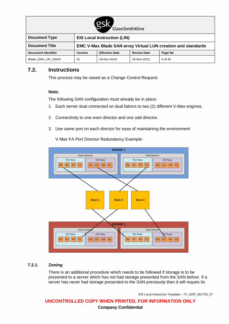
Note: The following SAN configuration must already be in place:
1. Each server dual connected on dual fabrics to two (2) different V-Max engines.
2. Connectivity to one even director and one odd director.
3. Use same port on each director for ease of maintaining the environment
V-Max FA Port Director Redundancy Example:
ENGINE 1
Even Director
FE Ports
E0 F1F0E1
FE Ports
G0 H1H0G1
Odd Director
FE Ports
E0 F1F0E1
FE Ports
G0 H1H0G1
ENGINE 2
Even Director
FE Ports
E0 F1F0E1
FE Ports
G0 H1H0G1
Odd Director
FE Ports
E0 F1F0E1
FE Ports
G0 H1H0G1
Host 1 Host 2 Host 3
7.2.1. Zoning
There is an additional procedure which needs to be followed if storage is to be presented to a server which has not had storage presented from the SAN before. If a server has never had storage presented to the SAN previously then it will require its
Document Type EIS Local Instruction (LIN)
Document Title EMC V-Max Blade SAN array Virtual LUN creation and standards Document Identifier Version Effective Date Review Date Page No
Blade_SAN_LIN_19520 01 19-Nov-2010 19-Nov-2012 6 of 40
EIS Local Instruction Template – ITI_SOP_001T03_07
UNCONTROLLED COPY WHEN PRINTED. FOR INFORMATION ONLY Company Confidential
SAN Fibre interface cards to be zoned to the SAN Fabrics. To zone a new server follow steps 1 – 18 as shown below.
1. Open Internet Explorer and enter either the switch name or IP address of the switch to which you want to connect. Login if prompted.
2. Enable the ports that will be used. Click on the Admin icon located under the switch illustration. Login if prompted.
3. Once in the Admin page, click on the ports tab. Place a check mark in the box of the port/ports that will need to be enabled. Click Apply then click close.
4. Click on the Zone Admin icon, shown at right, located in the lower-left corner of the GUI.
5. Log in using the switch administrator account and password.
6. Click on the Alias tab, then click Create. The Create New Alias box appears, prompting you to enter an alias name.
Notes:
An Alias should be created for each host and storage array. These will be grouped together to form a zone.
Aliases will be added to the zone list. The purpose of the alias in this case is to know what server is associated with a given World Wide Port Name (WWPN).
This keeps an administrator from having to research the WWPN to the server or storage array.
Enter the alias name, and then click OK.
7. Click on the WWNs icon in the Member Selection list.
8. Select the WWN that is associated with the server name that you entered as the alias name in step 6, then click Add FA host, which creates the new alias. Repeat steps 6 through 8 for each additional server as well as the storage arrays that are connected to the switch.
9. Click on the Zone tab, then click Create. The Create New Zone box appears.
10. Enter the Zone name and click OK.
11. Click on the Aliases icon in the Member Selection list.
12. Select the alias that is associated with the server zone name entered in step 10 and click Add member.
13. Select the alias associated with the storage array and click Add member. The two aliases are now part of a single initiator zone.
Document Type EIS Local Instruction (LIN)
Document Title EMC V-Max Blade SAN array Virtual LUN creation and standards Document Identifier Version Effective Date Review Date Page No
Blade_SAN_LIN_19520 01 19-Nov-2010 19-Nov-2012 7 of 40
EIS Local Instruction Template – ITI_SOP_001T03_07
UNCONTROLLED COPY WHEN PRINTED. FOR INFORMATION ONLY Company Confidential
Repeat steps 9 through 13 for each additional server zone set that you need to create.
14. If this a new installation where no configuration exists, proceed to step 15, if no, skip to step 18.
15. Click the Config tab, then click Create. The Create New Config name box opens.
16. Enter the configuration name and click OK.
17. Make sure that the active configuration that you intend to add this zone set to is selected in the Name box above the “Member Selection List”. Click on the Zones in the Member Selection list.
18. Select the zones that you want to be active and then click Add Member. Click on Actions in the menu, then click enable config. Select the configuration you created or a previous configuration to which you added new zones and click OK, then click Yes.
If the zoning committed successfully, you will see a ‘”Successfully committed the changes to the fabric” message in the bottom left hand corner of the window.
7.2.2. Create Virtual Pool Data Devices
Note: This section should only be used if the BIN file was not already built out with the appropriate TDAT’s needed for pool creation. Installation of new drives will be done by EMC and therefore they will update the BIN file with the correct settings and TDAT’s already built out. This section will rarely be used; it’s here in the event it’s needed for issues outside of the standards.
Symmetrix thin devices are logical devices that can be used in many of the same ways that Symmetrix devices have been traditionally used. Unlike traditional Symmetrix devices, thin devices do not need to have physical storage completely allocated at the time the device is allocated and presented to a host. A thin device is not usable until it has been bound to a virtual pool. The thin pool is comprised of data devices that provide actual storage to support the thin device allocations.
Best Practices: As a pre-cursor to creating a virtual LUN, it is recommended that the V-Max array have an updated BIN file with virtual pool devices (TDAT…data device) volumes already created. This is usually required when physical spindles are added to the storage array. It will allow EMC professional services to make the best recommendations around TDAT volume size and disk group configuration. Each TDAT volume should be 240GB or less in size to provide optimal performance per physical spindle. TDAT volumes should belong in their own disk group. TDAT volumes must be the same size and RAID protection per disk group. They must also belong to only one virtual pool at a time. Disk Drives in a pool MUST have the same rotational speed. The RAID protection
Document Type EIS Local Instruction (LIN)
Document Title EMC V-Max Blade SAN array Virtual LUN creation and standards Document Identifier Version Effective Date Review Date Page No
Blade_SAN_LIN_19520 01 19-Nov-2010 19-Nov-2012 8 of 40
EIS Local Instruction Template – ITI_SOP_001T03_07
UNCONTROLLED COPY WHEN PRINTED. FOR INFORMATION ONLY Company Confidential
of the LUNs must be the same. The wide striping provided by Virtual Provisioning will spread thin devices evenly across the data devices.
Concatenated thin Meta devices are recommended on the VMWare platform for the dual benefit of performance and ease of expansion. EMC does not recommend thin on thin provisioning to a host on VMWare where thin volumes are created at both the storage array and host layers. When creating and provisioning thin devices on VMWare, EMC recommends using the “zeroedthick” format which is the default format option on Symmetrix.
Create Data Devices
1. Login to SMC using Internet Explorer and login as the Administrator with the appropriate password.
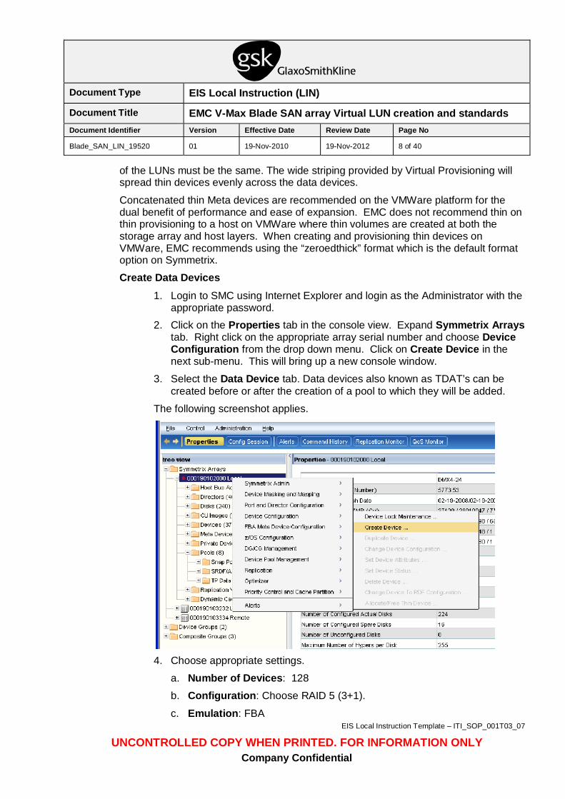
2. Click on the Properties tab in the console view. Expand Symmetrix Arrays tab. Right click on the appropriate array serial number and choose Device Configuration from the drop down menu. Click on Create Device in the next sub-menu. This will bring up a new console window.
3. Select the Data Device tab. Data devices also known as TDAT’s can be created before or after the creation of a pool to which they will be added.
The following screenshot applies.
4. Choose appropriate settings.
a. Number of Devices: 128
b. Configuration: Choose RAID 5 (3+1).
c. Emulation: FBA
Document Type EIS Local Instruction (LIN)
Document Title EMC V-Max Blade SAN array Virtual LUN creation and standards Document Identifier Version Effective Date Review Date Page No
Blade_SAN_LIN_19520 01 19-Nov-2010 19-Nov-2012 9 of 40
EIS Local Instruction Template – ITI_SOP_001T03_07
UNCONTROLLED COPY WHEN PRINTED. FOR INFORMATION ONLY Company Confidential
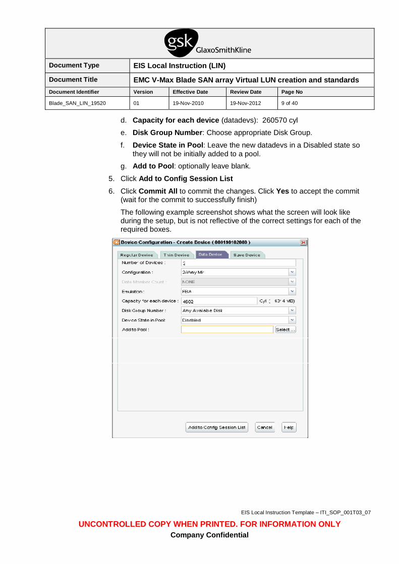
d. Capacity for each device (datadevs): 260570 cyl
e. Disk Group Number: Choose appropriate Disk Group.
f. Device State in Pool: Leave the new datadevs in a Disabled state so they will not be initially added to a pool.
g. Add to Pool: optionally leave blank.
5. Click Add to Config Session List 6. Click Commit All to commit the changes. Click Yes to accept the commit
(wait for the commit to successfully finish)
The following example screenshot shows what the screen will look like during the setup, but is not reflective of the correct settings for each of the required boxes.
Document Type EIS Local Instruction (LIN)
Document Title EMC V-Max Blade SAN array Virtual LUN creation and standards Document Identifier Version Effective Date Review Date Page No
Blade_SAN_LIN_19520 01 19-Nov-2010 19-Nov-2012 10 of 40
EIS Local Instruction Template – ITI_SOP_001T03_07
UNCONTROLLED COPY WHEN PRINTED. FOR INFORMATION ONLY Company Confidential
7.2.3. Create New Virtual Pool
Note: The following instructions will be used only if there are no existing Virtual Pools to use. Use this section only if directed to. Go to the next section to begin the process of provisioning if this section and the previous section have already been fulfilled.
1. Login to SMC using Internet Explorer and login as the Administrator with the appropriate password.
2. Click on the Properties tab at the top of the screen.
3. Expand the Symmetrix Arrays folder.
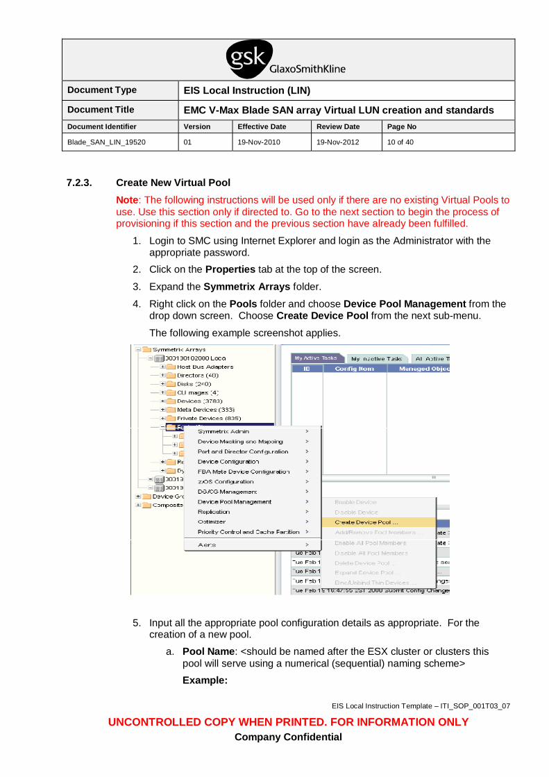
4. Right click on the Pools folder and choose Device Pool Management from the drop down screen. Choose Create Device Pool from the next sub-menu.
The following example screenshot applies.
5. Input all the appropriate pool configuration details as appropriate. For the creation of a new pool.
a. Pool Name: <should be named after the ESX cluster or clusters this pool will serve using a numerical (sequential) naming scheme> Example:
Document Type EIS Local Instruction (LIN)
Document Title EMC V-Max Blade SAN array Virtual LUN creation and standards Document Identifier Version Effective Date Review Date Page No
Blade_SAN_LIN_19520 01 19-Nov-2010 19-Nov-2012 11 of 40
EIS Local Instruction Template – ITI_SOP_001T03_07
UNCONTROLLED COPY WHEN PRINTED. FOR INFORMATION ONLY Company Confidential
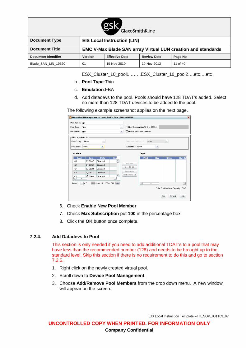
ESX_Cluster_10_pool1……..ESX_Cluster_10_pool2….etc….etc b. Pool Type:Thin
c. Emulation:FBA
d. Add datadevs to the pool. Pools should have 128 TDAT’s added. Select no more than 128 TDAT devices to be added to the pool.
The following example screenshot applies on the next page.
6. Check Enable New Pool Member 7. Check Max Subscription put 100 in the percentage box.
8. Click the OK button once complete.
7.2.4. Add Datadevs to Pool
This section is only needed if you need to add additional TDAT’s to a pool that may have less than the recommended number (128) and needs to be brought up to the standard level. Skip this section if there is no requirement to do this and go to section 7.2.5.
1. Right click on the newly created virtual pool.
2. Scroll down to Device Pool Management. 3. Choose Add/Remove Pool Members from the drop down menu. A new window
will appear on the screen.
Document Type EIS Local Instruction (LIN)
Document Title EMC V-Max Blade SAN array Virtual LUN creation and standards Document Identifier Version Effective Date Review Date Page No
Blade_SAN_LIN_19520 01 19-Nov-2010 19-Nov-2012 12 of 40
EIS Local Instruction Template – ITI_SOP_001T03_07
UNCONTROLLED COPY WHEN PRINTED. FOR INFORMATION ONLY Company Confidential
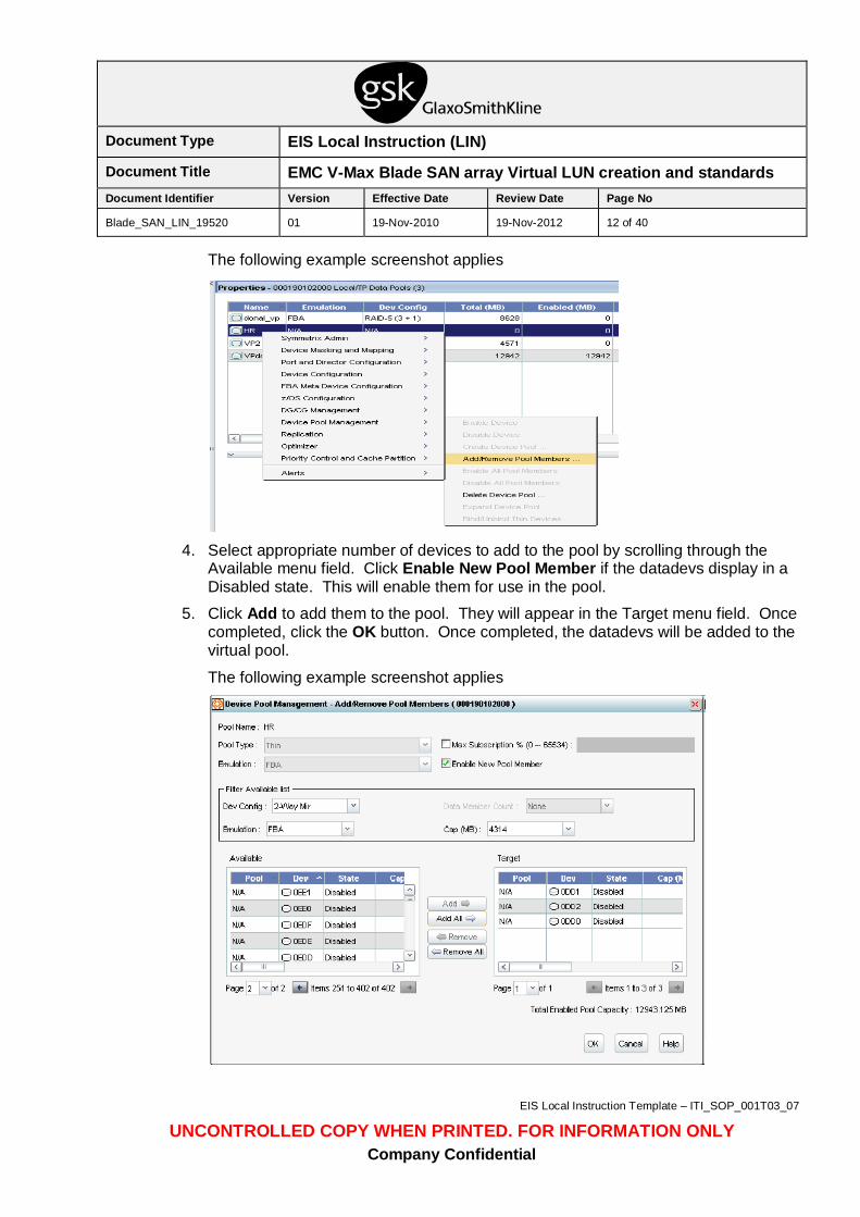
The following example screenshot applies
4. Select appropriate number of devices to add to the pool by scrolling through the
Available menu field. Click Enable New Pool Member if the datadevs display in a Disabled state. This will enable them for use in the pool.
5. Click Add to add them to the pool. They will appear in the Target menu field. Once completed, click the OK button. Once completed, the datadevs will be added to the virtual pool.
The following example screenshot applies
Document Type EIS Local Instruction (LIN)
Document Title EMC V-Max Blade SAN array Virtual LUN creation and standards Document Identifier Version Effective Date Review Date Page No
Blade_SAN_LIN_19520 01 19-Nov-2010 19-Nov-2012 13 of 40
EIS Local Instruction Template – ITI_SOP_001T03_07
UNCONTROLLED COPY WHEN PRINTED. FOR INFORMATION ONLY Company Confidential
7.2.5. Create a Thin Volume
Important: ESX 3.5 and ESX 4.0 servers MUST not share the same LUN’s. Make sure when creating these, if there is a situation where the array is hosting ESX 3.5 and 4.0, do not share the LUN. This should already be common practice as ESX clusters are separated by version.
1. Click on the Properties tab in the console view. Expand Symmetrix Arrays tab. Right click on the appropriate array serial number and choose Device Configuration from the drop down menu. Click on Create Device in the next sub-menu. This will bring up a new console window.
2. Click on the Thin Device tab.
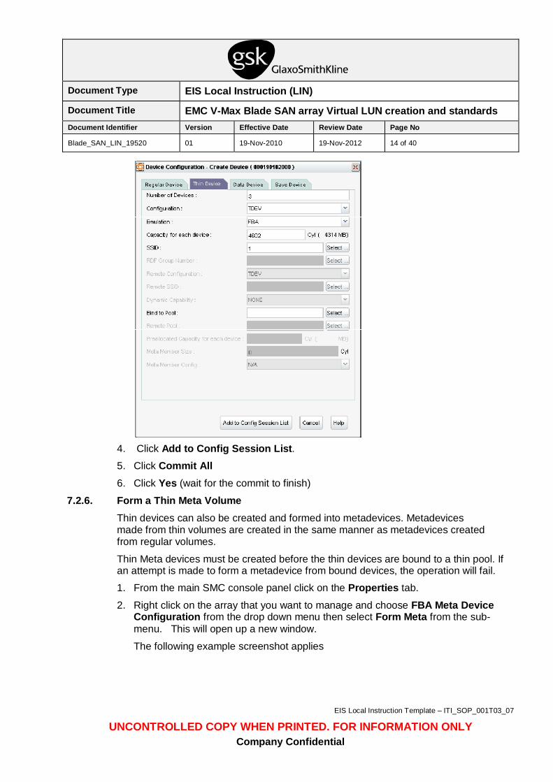
3. Enter appropriate system information for your environment.
a. Number of Devices: 5
b. Configuration:TDEV (Thin Device)
c. Emulation: FBA
d. Capacity for each device: 163840
e. Bind to Pool: Choose the appropriate pool that this Thin Device will be created from.
The following example screenshot shows what the screen will look like during the setup, but is not reflective of the correct settings for each of the required boxes.
Document Type EIS Local Instruction (LIN)
Document Title EMC V-Max Blade SAN array Virtual LUN creation and standards Document Identifier Version Effective Date Review Date Page No
Blade_SAN_LIN_19520 01 19-Nov-2010 19-Nov-2012 14 of 40
EIS Local Instruction Template – ITI_SOP_001T03_07
UNCONTROLLED COPY WHEN PRINTED. FOR INFORMATION ONLY Company Confidential
4. Click Add to Config Session List. 5. Click Commit All 6. Click Yes (wait for the commit to finish)
7.2.6. Form a Thin Meta Volume Thin devices can also be created and formed into metadevices. Metadevices made from thin volumes are created in the same manner as metadevices created from regular volumes.
Thin Meta devices must be created before the thin devices are bound to a thin pool. If an attempt is made to form a metadevice from bound devices, the operation will fail.
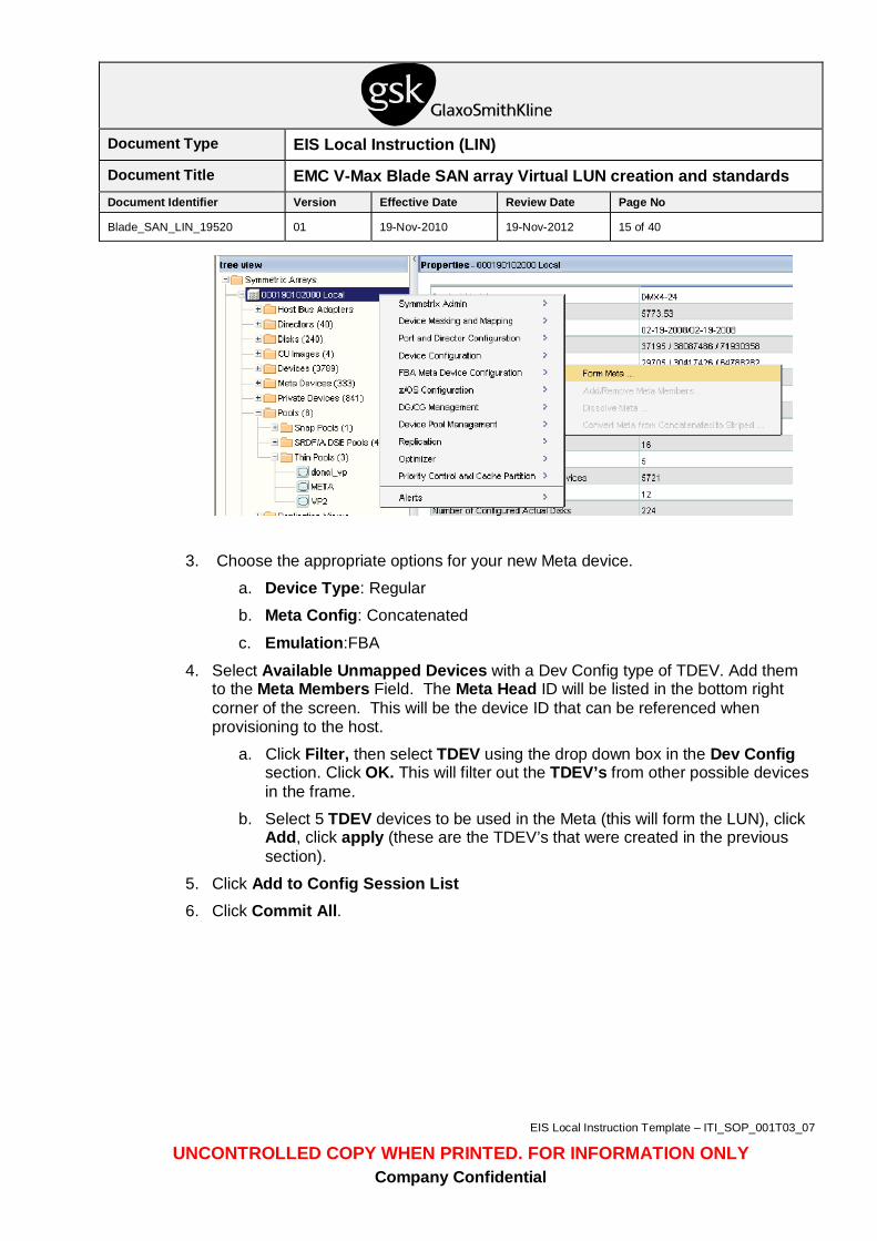
1. From the main SMC console panel click on the Properties tab.
2. Right click on the array that you want to manage and choose FBA Meta Device Configuration from the drop down menu then select Form Meta from the sub-menu. This will open up a new window. The following example screenshot applies
Document Type EIS Local Instruction (LIN)
Document Title EMC V-Max Blade SAN array Virtual LUN creation and standards Document Identifier Version Effective Date Review Date Page No
Blade_SAN_LIN_19520 01 19-Nov-2010 19-Nov-2012 15 of 40
EIS Local Instruction Template – ITI_SOP_001T03_07
UNCONTROLLED COPY WHEN PRINTED. FOR INFORMATION ONLY Company Confidential
3. Choose the appropriate options for your new Meta device.
a. Device Type: Regular
b. Meta Config: Concatenated
c. Emulation:FBA
4. Select Available Unmapped Devices with a Dev Config type of TDEV. Add them to the Meta Members Field. The Meta Head ID will be listed in the bottom right corner of the screen. This will be the device ID that can be referenced when provisioning to the host.
a. Click Filter, then select TDEV using the drop down box in the Dev Config section. Click OK. This will filter out the TDEV’s from other possible devices in the frame.
b. Select 5 TDEV devices to be used in the Meta (this will form the LUN), click Add, click apply (these are the TDEV’s that were created in the previous section).
5. Click Add to Config Session List 6. Click Commit All.
Document Type EIS Local Instruction (LIN)
Document Title EMC V-Max Blade SAN array Virtual LUN creation and standards Document Identifier Version Effective Date Review Date Page No
Blade_SAN_LIN_19520 01 19-Nov-2010 19-Nov-2012 16 of 40
EIS Local Instruction Template – ITI_SOP_001T03_07
UNCONTROLLED COPY WHEN PRINTED. FOR INFORMATION ONLY Company Confidential
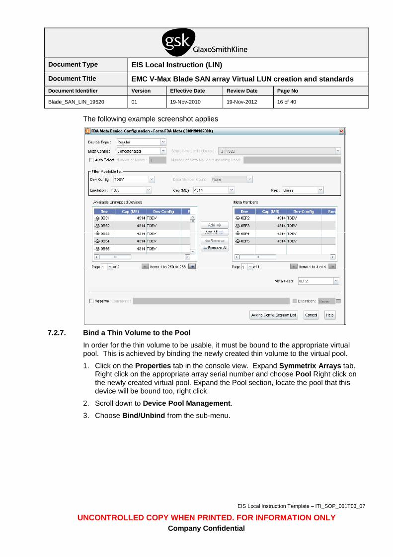
The following example screenshot applies
7.2.7. Bind a Thin Volume to the Pool
In order for the thin volume to be usable, it must be bound to the appropriate virtual pool. This is achieved by binding the newly created thin volume to the virtual pool.
1. Click on the Properties tab in the console view. Expand Symmetrix Arrays tab. Right click on the appropriate array serial number and choose Pool Right click on the newly created virtual pool. Expand the Pool section, locate the pool that this device will be bound too, right click.
2. Scroll down to Device Pool Management. 3. Choose Bind/Unbind from the sub-menu.
Document Type EIS Local Instruction (LIN)
Document Title EMC V-Max Blade SAN array Virtual LUN creation and standards Document Identifier Version Effective Date Review Date Page No
Blade_SAN_LIN_19520 01 19-Nov-2010 19-Nov-2012 17 of 40
EIS Local Instruction Template – ITI_SOP_001T03_07
UNCONTROLLED COPY WHEN PRINTED. FOR INFORMATION ONLY Company Confidential
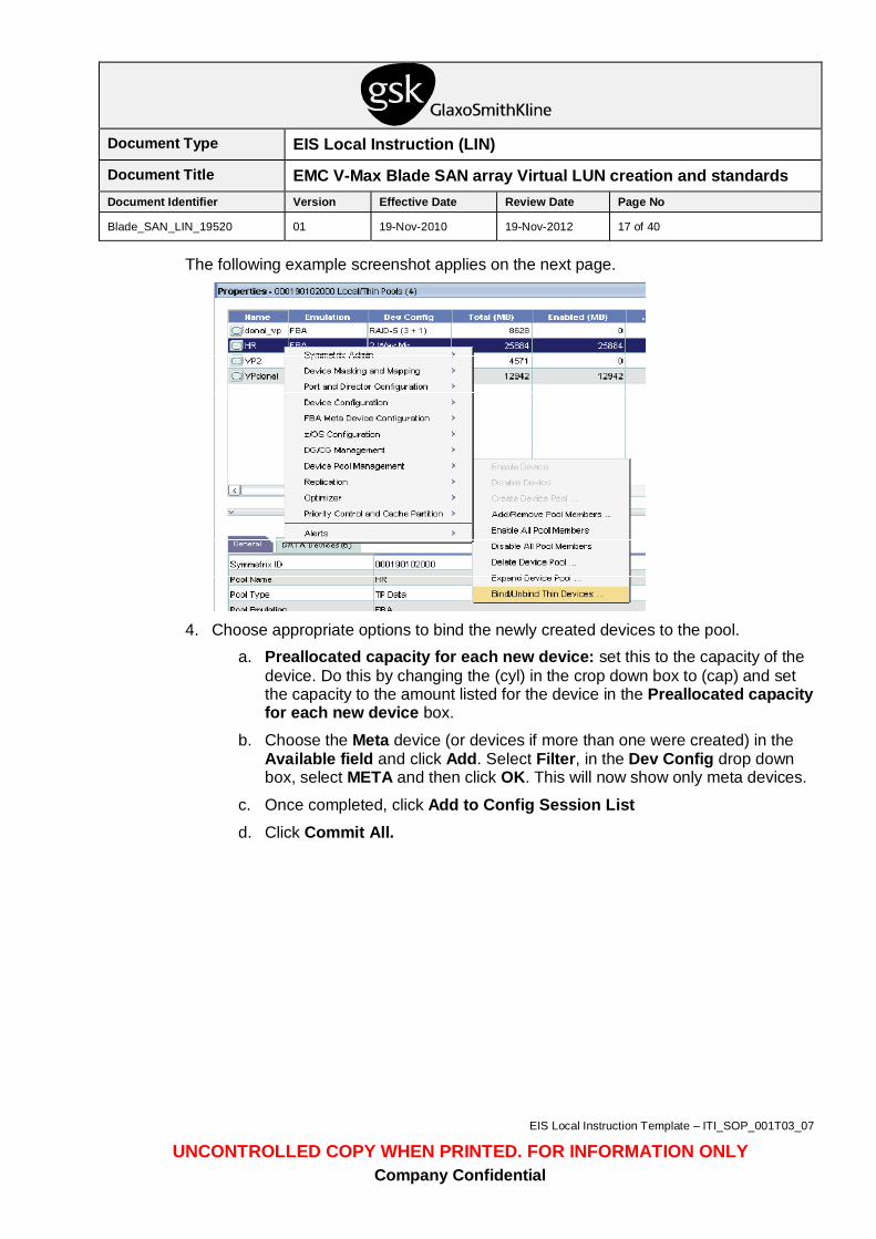
The following example screenshot applies on the next page.
4. Choose appropriate options to bind the newly created devices to the pool.
a. Preallocated capacity for each new device: set this to the capacity of the device. Do this by changing the (cyl) in the crop down box to (cap) and set the capacity to the amount listed for the device in the Preallocated capacity for each new device box.
b. Choose the Meta device (or devices if more than one were created) in the Available field and click Add. Select Filter, in the Dev Config drop down box, select META and then click OK. This will now show only meta devices.
c. Once completed, click Add to Config Session List d. Click Commit All.
Document Type EIS Local Instruction (LIN)
Document Title EMC V-Max Blade SAN array Virtual LUN creation and standards Document Identifier Version Effective Date Review Date Page No
Blade_SAN_LIN_19520 01 19-Nov-2010 19-Nov-2012 18 of 40
EIS Local Instruction Template – ITI_SOP_001T03_07
UNCONTROLLED COPY WHEN PRINTED. FOR INFORMATION ONLY Company Confidential
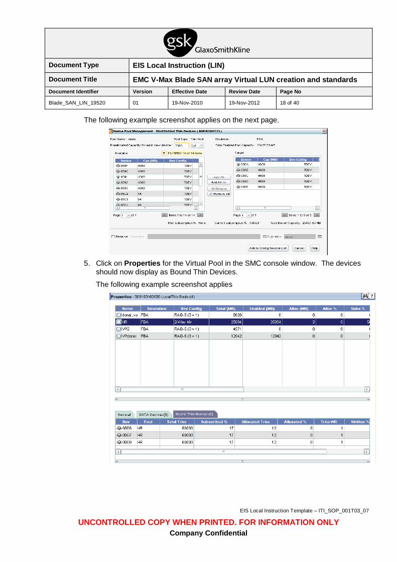
The following example screenshot applies on the next page.
5. Click on Properties for the Virtual Pool in the SMC console window. The devices
should now display as Bound Thin Devices.
The following example screenshot applies
Document Type EIS Local Instruction (LIN)
Document Title EMC V-Max Blade SAN array Virtual LUN creation and standards Document Identifier Version Effective Date Review Date Page No
Blade_SAN_LIN_19520 01 19-Nov-2010 19-Nov-2012 19 of 40
EIS Local Instruction Template – ITI_SOP_001T03_07
UNCONTROLLED COPY WHEN PRINTED. FOR INFORMATION ONLY Company Confidential
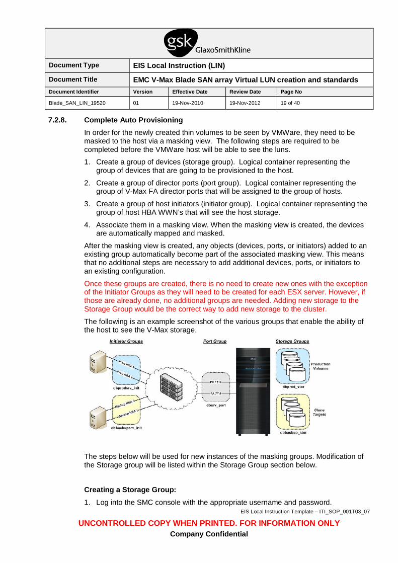
7.2.8. Complete Auto Provisioning In order for the newly created thin volumes to be seen by VMWare, they need to be masked to the host via a masking view. The following steps are required to be completed before the VMWare host will be able to see the luns.
1. Create a group of devices (storage group). Logical container representing the group of devices that are going to be provisioned to the host.
2. Create a group of director ports (port group). Logical container representing the group of V-Max FA director ports that will be assigned to the group of hosts.
3. Create a group of host initiators (initiator group). Logical container representing the group of host HBA WWN’s that will see the host storage.
4. Associate them in a masking view. When the masking view is created, the devices are automatically mapped and masked.
After the masking view is created, any objects (devices, ports, or initiators) added to an existing group automatically become part of the associated masking view. This means that no additional steps are necessary to add additional devices, ports, or initiators to an existing configuration.
Once these groups are created, there is no need to create new ones with the exception of the Initiator Groups as they will need to be created for each ESX server. However, if those are already done, no additional groups are needed. Adding new storage to the Storage Group would be the correct way to add new storage to the cluster.
The following is an example screenshot of the various groups that enable the ability of the host to see the V-Max storage.
The steps below will be used for new instances of the masking groups. Modification of the Storage group will be listed within the Storage Group section below.
Creating a Storage Group: 1. Log into the SMC console with the appropriate username and password.
Document Type EIS Local Instruction (LIN)
Document Title EMC V-Max Blade SAN array Virtual LUN creation and standards Document Identifier Version Effective Date Review Date Page No
Blade_SAN_LIN_19520 01 19-Nov-2010 19-Nov-2012 20 of 40
EIS Local Instruction Template – ITI_SOP_001T03_07
UNCONTROLLED COPY WHEN PRINTED. FOR INFORMATION ONLY Company Confidential
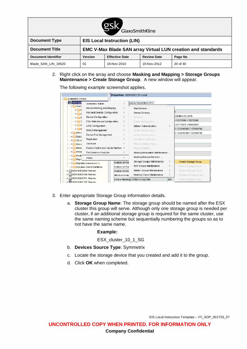
2. Right click on the array and choose Masking and Mapping > Storage Groups Maintenance > Create Storage Group. A new window will appear.
The following example screenshot applies.
3. Enter appropriate Storage Group information details. a. Storage Group Name: The storage group should be named after the ESX
cluster this group will serve. Although only one storage group is needed per cluster, if an additional storage group is required for the same cluster, use the same naming scheme but sequentially numbering the groups so as to not have the same name.
Example: ESX_cluster_10_1_SG
b. Devices Source Type: Symmetrix
c. Locate the storage device that you created and add it to the group.
d. Click OK when completed.
Document Type EIS Local Instruction (LIN)
Document Title EMC V-Max Blade SAN array Virtual LUN creation and standards Document Identifier Version Effective Date Review Date Page No
Blade_SAN_LIN_19520 01 19-Nov-2010 19-Nov-2012 21 of 40
EIS Local Instruction Template – ITI_SOP_001T03_07
UNCONTROLLED COPY WHEN PRINTED. FOR INFORMATION ONLY Company Confidential
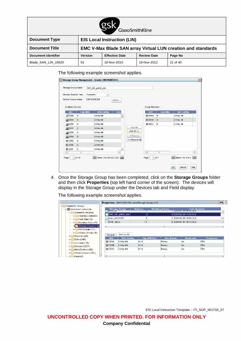
The following example screenshot applies.
4. Once the Storage Group has been completed, click on the Storage Groups folder
and then click Properties (top left hand corner of the screen). The devices will display in the Storage Group under the Devices tab and Field display.
The following example screenshot applies.
Document Type EIS Local Instruction (LIN)
Document Title EMC V-Max Blade SAN array Virtual LUN creation and standards Document Identifier Version Effective Date Review Date Page No
Blade_SAN_LIN_19520 01 19-Nov-2010 19-Nov-2012 22 of 40
EIS Local Instruction Template – ITI_SOP_001T03_07
UNCONTROLLED COPY WHEN PRINTED. FOR INFORMATION ONLY Company Confidential
Adding new devices to the Storage Group To modify the storage group to add new devices, right click on the array and choose Masking and Mapping > Storage Groups Maintenance > Modify Storage Group. A new window will appear.
a. Devices Source Type: Symmetrix
b. Locate the storage device that you created and add it to the group
c. Click OK when completed
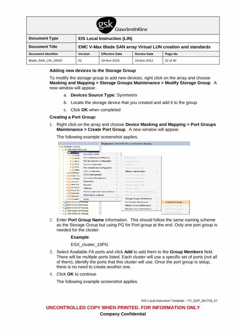
Creating a Port Group: 1. Right click on the array and choose Device Masking and Mapping > Port Groups
Maintenance > Create Port Group. A new window will appear.
The following example screenshot applies.
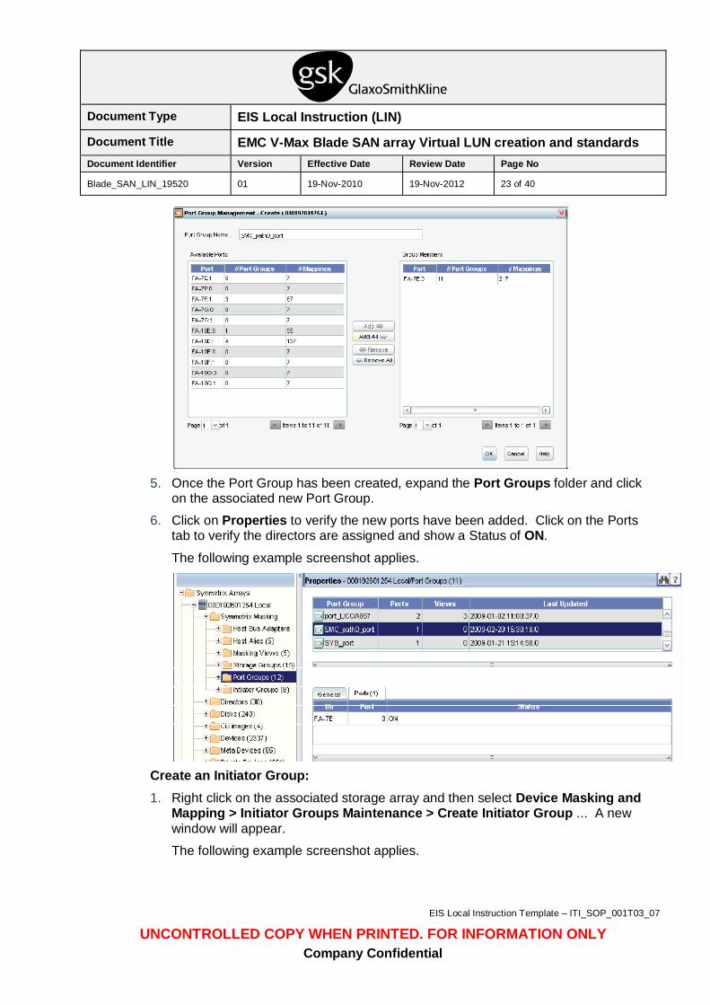
2. Enter Port Group Name information. This should follow the same naming scheme
as the Storage Group but using PG for Port group at the end. Only one port group is needed for the cluster.
Example:
ESX_cluster_10PG
3. Select Available FA ports and click Add to add them to the Group Members field. There will be multiple ports listed. Each cluster will use a specific set of ports (not all of them), identify the ports that this cluster will use. Once the port group is setup, there is no need to create another one.
4. Click OK to continue.
The following example screenshot applies.
Document Type EIS Local Instruction (LIN)
Document Title EMC V-Max Blade SAN array Virtual LUN creation and standards Document Identifier Version Effective Date Review Date Page No
Blade_SAN_LIN_19520 01 19-Nov-2010 19-Nov-2012 23 of 40
EIS Local Instruction Template – ITI_SOP_001T03_07
UNCONTROLLED COPY WHEN PRINTED. FOR INFORMATION ONLY Company Confidential
5. Once the Port Group has been created, expand the Port Groups folder and click
on the associated new Port Group.
6. Click on Properties to verify the new ports have been added. Click on the Ports tab to verify the directors are assigned and show a Status of ON.
The following example screenshot applies.
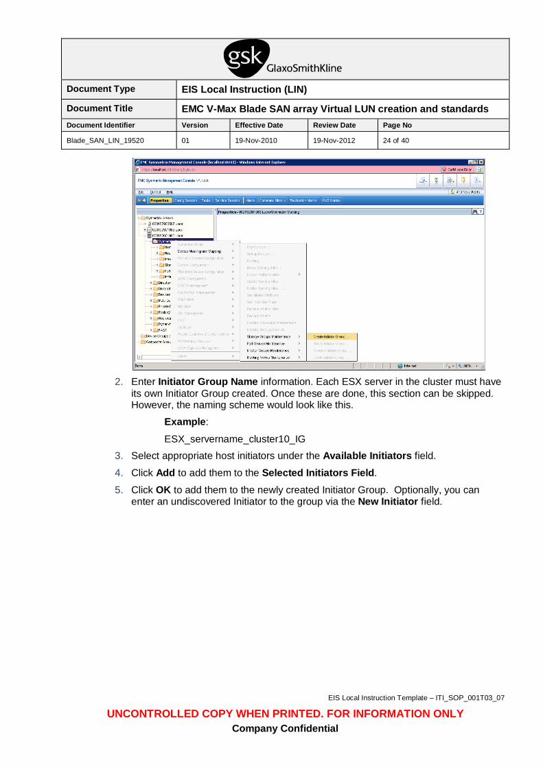
Create an Initiator Group: 1. Right click on the associated storage array and then select Device Masking and
Mapping > Initiator Groups Maintenance > Create Initiator Group ... A new window will appear.
The following example screenshot applies.
Document Type EIS Local Instruction (LIN)
Document Title EMC V-Max Blade SAN array Virtual LUN creation and standards Document Identifier Version Effective Date Review Date Page No
Blade_SAN_LIN_19520 01 19-Nov-2010 19-Nov-2012 24 of 40
EIS Local Instruction Template – ITI_SOP_001T03_07
UNCONTROLLED COPY WHEN PRINTED. FOR INFORMATION ONLY Company Confidential
2. Enter Initiator Group Name information. Each ESX server in the cluster must have
its own Initiator Group created. Once these are done, this section can be skipped. However, the naming scheme would look like this.
Example:
ESX_servername_cluster10_IG 3. Select appropriate host initiators under the Available Initiators field.
4. Click Add to add them to the Selected Initiators Field.
5. Click OK to add them to the newly created Initiator Group. Optionally, you can enter an undiscovered Initiator to the group via the New Initiator field.
Document Type EIS Local Instruction (LIN)
Document Title EMC V-Max Blade SAN array Virtual LUN creation and standards Document Identifier Version Effective Date Review Date Page No
Blade_SAN_LIN_19520 01 19-Nov-2010 19-Nov-2012 25 of 40
EIS Local Instruction Template – ITI_SOP_001T03_07
UNCONTROLLED COPY WHEN PRINTED. FOR INFORMATION ONLY Company Confidential
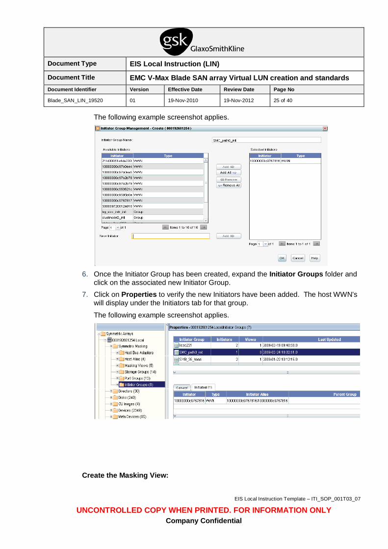
The following example screenshot applies.
6. Once the Initiator Group has been created, expand the Initiator Groups folder and
click on the associated new Initiator Group. 7. Click on Properties to verify the new Initiators have been added. The host WWN’s
will display under the Initiators tab for that group.
The following example screenshot applies.
Create the Masking View:
Document Type EIS Local Instruction (LIN)
Document Title EMC V-Max Blade SAN array Virtual LUN creation and standards Document Identifier Version Effective Date Review Date Page No
Blade_SAN_LIN_19520 01 19-Nov-2010 19-Nov-2012 26 of 40
EIS Local Instruction Template – ITI_SOP_001T03_07
UNCONTROLLED COPY WHEN PRINTED. FOR INFORMATION ONLY Company Confidential
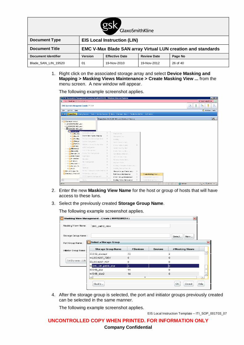
1. Right click on the associated storage array and select Device Masking and Mapping > Masking Views Maintenance > Create Masking View ... from the menu screen. A new window will appear.
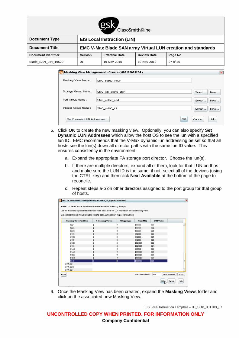
The following example screenshot applies.
2. Enter the new Masking View Name for the host or group of hosts that will have
access to these luns.
3. Select the previously created Storage Group Name.
The following example screenshot applies.
4. After the storage group is selected, the port and initiator groups previously created
can be selected in the same manner.
The following example screenshot applies.
Document Type EIS Local Instruction (LIN)
Document Title EMC V-Max Blade SAN array Virtual LUN creation and standards Document Identifier Version Effective Date Review Date Page No
Blade_SAN_LIN_19520 01 19-Nov-2010 19-Nov-2012 27 of 40
EIS Local Instruction Template – ITI_SOP_001T03_07
UNCONTROLLED COPY WHEN PRINTED. FOR INFORMATION ONLY Company Confidential
5. Click OK to create the new masking view. Optionally, you can also specify Set
Dynamic LUN Addresses which allow the host OS to see the lun with a specified lun ID. EMC recommends that the V-Max dynamic lun addressing be set so that all hosts see the lun(s) down all director paths with the same lun ID value. This ensures consistency in the environment.
a. Expand the appropriate FA storage port director. Choose the lun(s).
b. If there are multiple directors, expand all of them, look for that LUN on thos and make sure the LUN ID is the same, if not, select all of the devices (using the CTRL key) and then click Next Available at the bottom of the page to reconcile.
c. Repeat steps a-b on other directors assigned to the port group for that group of hosts.
6. Once the Masking View has been created, expand the Masking Views folder and
click on the associated new Masking View.
Document Type EIS Local Instruction (LIN)
Document Title EMC V-Max Blade SAN array Virtual LUN creation and standards Document Identifier Version Effective Date Review Date Page No
Blade_SAN_LIN_19520 01 19-Nov-2010 19-Nov-2012 28 of 40
EIS Local Instruction Template – ITI_SOP_001T03_07
UNCONTROLLED COPY WHEN PRINTED. FOR INFORMATION ONLY Company Confidential
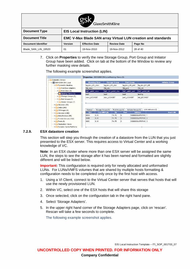
7. Click on Properties to verify the new Storage Group, Port Group and Initiator Group have been added. Click on tab at the bottom of the Window to review any further masking view details.
The following example screenshot applies.
7.2.9. ESX datastore creation
This section will step you through the creation of a datastore from the LUN that you just presented to the ESX server. This requires access to Virtual Center and a working knowledge of VC.
Note: In an ESX cluster where more than one ESX server will be assigned the same LUN, the steps to see the storage after it has been named and formatted are slightly different and will be listed below. Important: This configuration is required only for newly allocated and unformatted LUNs. For LUNs/VMFS volumes that are shared by multiple hosts formatting & configuration needs to be completed only once by the first host with access.
1. Using a VI Client, connect to the Virtual Center server that serves that hosts that will use the newly provisioned LUN.
2. Within VC, select one of the ESX hosts that will share this storage
3. Once selected, click on the configuration tab in the right hand pane.
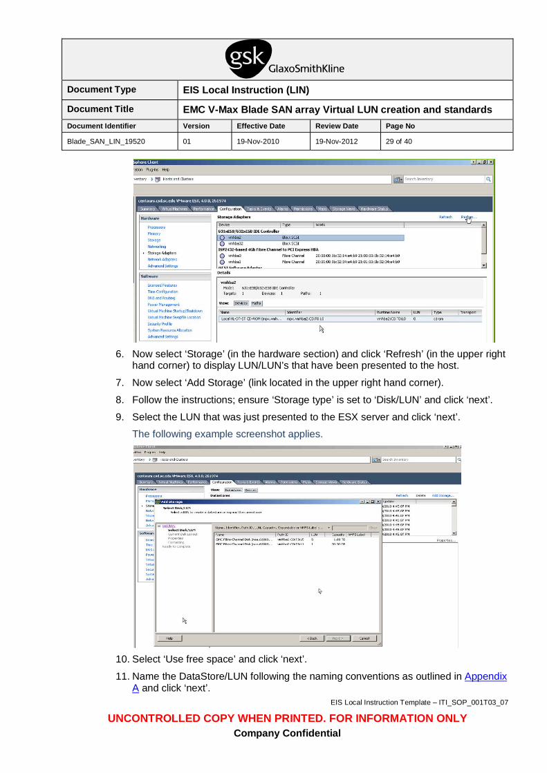
4. Select ‘Storage Adapters’.
5. In the upper right hand corner of the Storage Adapters page, click on ‘rescan’. Rescan will take a few seconds to complete.
The following example screenshot applies.
Document Type EIS Local Instruction (LIN)
Document Title EMC V-Max Blade SAN array Virtual LUN creation and standards Document Identifier Version Effective Date Review Date Page No
Blade_SAN_LIN_19520 01 19-Nov-2010 19-Nov-2012 29 of 40
EIS Local Instruction Template – ITI_SOP_001T03_07
UNCONTROLLED COPY WHEN PRINTED. FOR INFORMATION ONLY Company Confidential
6. Now select ‘Storage’ (in the hardware section) and click ‘Refresh’ (in the upper right
hand corner) to display LUN/LUN’s that have been presented to the host.
7. Now select ‘Add Storage’ (link located in the upper right hand corner).
8. Follow the instructions; ensure ‘Storage type’ is set to ‘Disk/LUN’ and click ‘next’.
9. Select the LUN that was just presented to the ESX server and click ‘next’.
The following example screenshot applies.
10. Select ‘Use free space’ and click ‘next’.
11. Name the DataStore/LUN following the naming conventions as outlined in Appendix A and click ‘next’.
Document Type EIS Local Instruction (LIN)
Document Title EMC V-Max Blade SAN array Virtual LUN creation and standards Document Identifier Version Effective Date Review Date Page No
Blade_SAN_LIN_19520 01 19-Nov-2010 19-Nov-2012 30 of 40
EIS Local Instruction Template – ITI_SOP_001T03_07
UNCONTROLLED COPY WHEN PRINTED. FOR INFORMATION ONLY Company Confidential
12. Use the dropdown box and select the ‘Maximum File Size’ of ‘2048GB , Block Size: 8MB’ and ensure ‘Maximize Capacity’ is checked in the capacity section, then click ‘next’.
13. Check the Proposed disk layout and the disk properties are correct. Use the ‘back’ option to make any corrections if needed.
14. Click Finish.
15. Formatting will now occur, depending on the size of the VMFS LUN, it may take several minutes to complete the formatting. Wait for the format to complete.
16. Once the formatting has completed, set/verify the pathing to the LUN/VMFS volume.
a. Within VC, click on the ESX server, click on the Configuration tab, click Storage, in the DataStores list select and right click the datastore/LUN that was just presented and select Properties. A new window will appear.
b. Select Managed Paths and verify that the Path Selection policy at the top of the page is set to Round Robin. If not, using the drop down box, select Round Robin and click close.
c. Close the Properties box.
17. Since the LUN will be a shared data source, after the DataStore has been created, you must now update each ESX server that will have access to that LUN. Repeat steps 1 – 6 above for each ESX server that will share the LUN. DO NOT repeat any other steps other than steps 1 – 6 and 16. Use step 16 above to verify that the Path Selection Policy is set to Round Robin for each ESX server that will share this datastore.
a. Once the rescan has been done, the datastore will now be listed in the Datastore section under the Summary tab of the ESX server.
b.
7.3. Post Execution Verification Verification is a successfully created storage LUN presented to a host. Successful verification may be obtained from the group that is responsible for the server hardware to which the storage was offered.
Using VC, login (if not already there), navigate to the ESX server that you initially presented the storage too, on the right select the configuration tab, then select storage. Take a screen shot as evidence to show the DataStore/LUN that was presented.
To verify that all ESX servers within the cluster see the datastore, repeat the process explained in the previous paragraph.
Output of both commands shall be placed in the Change Control by adding it as a file.
The verification for the pathing of the datastore is part of section 7.2.6 in step 16.
Document Type EIS Local Instruction (LIN)
Document Title EMC V-Max Blade SAN array Virtual LUN creation and standards Document Identifier Version Effective Date Review Date Page No
Blade_SAN_LIN_19520 01 19-Nov-2010 19-Nov-2012 31 of 40
EIS Local Instruction Template – ITI_SOP_001T03_07
UNCONTROLLED COPY WHEN PRINTED. FOR INFORMATION ONLY Company Confidential
7.4. Back-out Instructions
7.4.1. Delete Datastore from ESX host If the datastore creation was unsuccessful, remove the datastore within VC. Note: This assumes the datastore has no data written to it and is only being executed because of an issue within the creation process. Only remove this if it is absolutely necessary.
1. Using a VI Client, connect to the ESX Host directly or via Virtual Center.
2. Within VC, select the ESX Host, and open the Configuration Tab.
3. Select Storage
4. Click Delete and select Yes. This will permanently delete the datastore. Note: These instructions assume that the LUN that was presented has no data and this back-out is being executed because of a mistake/problem with the creation in section 7.2.
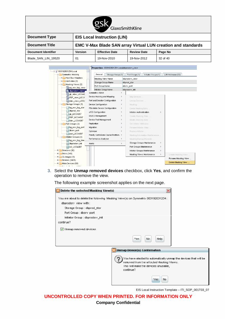
7.4.2. Delete Masking View and Auto-Provisioned Groups Delete Masking View: After the device has been removed from the ESX host(s) the masking view must be deleted from the storage via the SMC console. To remove access of that device by deleting the masking view, complete the following steps:
1. The dialog box used to delete views can be accessed by right-clicking on the masking view in the Properties pane.
2. Chose Device Masking and Mapping > Masking Views Maintenance > Delete Masking View ... from the drop down menu. A new window will appear.
The following example screenshot applies.
Document Type EIS Local Instruction (LIN)
Document Title EMC V-Max Blade SAN array Virtual LUN creation and standards Document Identifier Version Effective Date Review Date Page No
Blade_SAN_LIN_19520 01 19-Nov-2010 19-Nov-2012 32 of 40
EIS Local Instruction Template – ITI_SOP_001T03_07
UNCONTROLLED COPY WHEN PRINTED. FOR INFORMATION ONLY Company Confidential
3. Select the Unmap removed devices checkbox, click Yes, and confirm the
operation to remove the view.
The following example screenshot applies on the next page.
Document Type EIS Local Instruction (LIN)
Document Title EMC V-Max Blade SAN array Virtual LUN creation and standards Document Identifier Version Effective Date Review Date Page No
Blade_SAN_LIN_19520 01 19-Nov-2010 19-Nov-2012 33 of 40
EIS Local Instruction Template – ITI_SOP_001T03_07
UNCONTROLLED COPY WHEN PRINTED. FOR INFORMATION ONLY Company Confidential
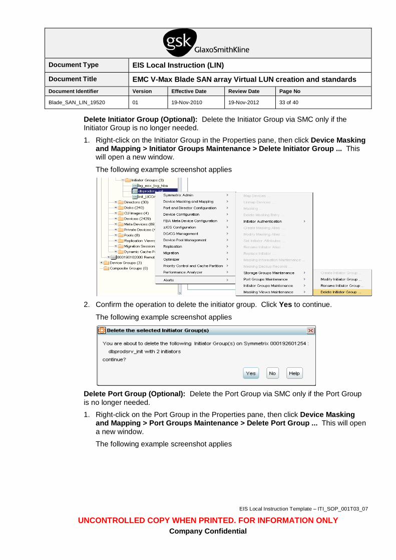
Delete Initiator Group (Optional): Delete the Initiator Group via SMC only if the Initiator Group is no longer needed.
1. Right-click on the Initiator Group in the Properties pane, then click Device Masking and Mapping > Initiator Groups Maintenance > Delete Initiator Group ... This will open a new window.
The following example screenshot applies
2. Confirm the operation to delete the initiator group. Click Yes to continue.
The following example screenshot applies
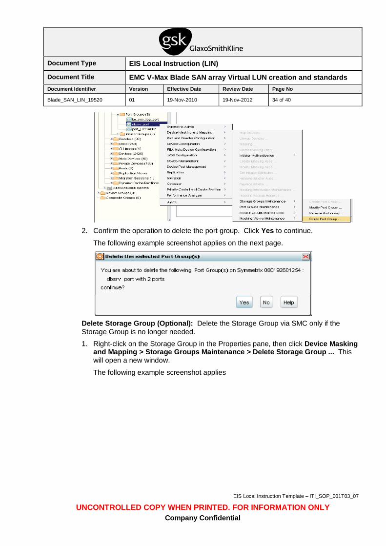
Delete Port Group (Optional): Delete the Port Group via SMC only if the Port Group is no longer needed. 1. Right-click on the Port Group in the Properties pane, then click Device Masking
and Mapping > Port Groups Maintenance > Delete Port Group ... This will open a new window.
The following example screenshot applies
Document Type EIS Local Instruction (LIN)
Document Title EMC V-Max Blade SAN array Virtual LUN creation and standards Document Identifier Version Effective Date Review Date Page No
Blade_SAN_LIN_19520 01 19-Nov-2010 19-Nov-2012 34 of 40
EIS Local Instruction Template – ITI_SOP_001T03_07
UNCONTROLLED COPY WHEN PRINTED. FOR INFORMATION ONLY Company Confidential
2. Confirm the operation to delete the port group. Click Yes to continue.
The following example screenshot applies on the next page.
Delete Storage Group (Optional): Delete the Storage Group via SMC only if the Storage Group is no longer needed.
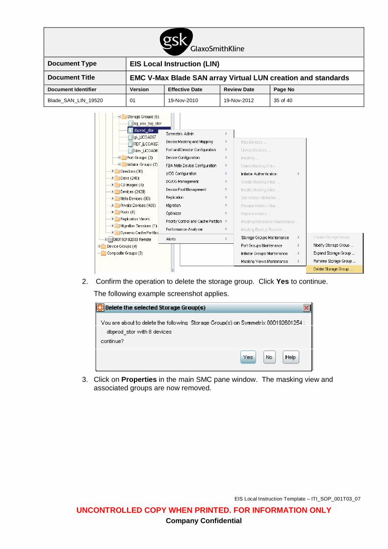
1. Right-click on the Storage Group in the Properties pane, then click Device Masking and Mapping > Storage Groups Maintenance > Delete Storage Group ... This will open a new window.
The following example screenshot applies
Document Type EIS Local Instruction (LIN)
Document Title EMC V-Max Blade SAN array Virtual LUN creation and standards Document Identifier Version Effective Date Review Date Page No
Blade_SAN_LIN_19520 01 19-Nov-2010 19-Nov-2012 35 of 40
EIS Local Instruction Template – ITI_SOP_001T03_07
UNCONTROLLED COPY WHEN PRINTED. FOR INFORMATION ONLY Company Confidential
2. Confirm the operation to delete the storage group. Click Yes to continue.
The following example screenshot applies.
3. Click on Properties in the main SMC pane window. The masking view and
associated groups are now removed.
Document Type EIS Local Instruction (LIN)
Document Title EMC V-Max Blade SAN array Virtual LUN creation and standards Document Identifier Version Effective Date Review Date Page No
Blade_SAN_LIN_19520 01 19-Nov-2010 19-Nov-2012 36 of 40
EIS Local Instruction Template – ITI_SOP_001T03_07
UNCONTROLLED COPY WHEN PRINTED. FOR INFORMATION ONLY Company Confidential
The following example screenshot applies
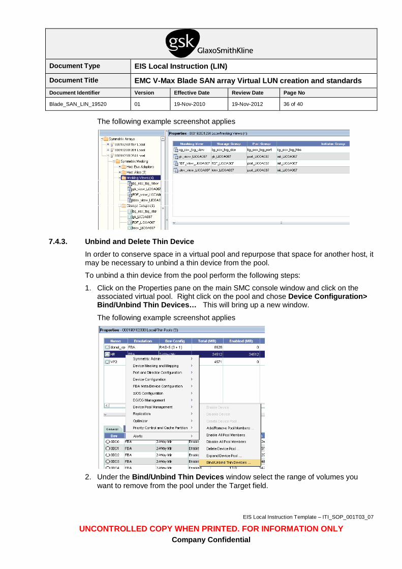
7.4.3. Unbind and Delete Thin Device In order to conserve space in a virtual pool and repurpose that space for another host, it may be necessary to unbind a thin device from the pool.
To unbind a thin device from the pool perform the following steps:
1. Click on the Properties pane on the main SMC console window and click on the associated virtual pool. Right click on the pool and chose Device Configuration> Bind/Unbind Thin Devices… This will bring up a new window. The following example screenshot applies
2. Under the Bind/Unbind Thin Devices window select the range of volumes you
want to remove from the pool under the Target field.
Document Type EIS Local Instruction (LIN)
Document Title EMC V-Max Blade SAN array Virtual LUN creation and standards Document Identifier Version Effective Date Review Date Page No
Blade_SAN_LIN_19520 01 19-Nov-2010 19-Nov-2012 37 of 40
EIS Local Instruction Template – ITI_SOP_001T03_07
UNCONTROLLED COPY WHEN PRINTED. FOR INFORMATION ONLY Company Confidential
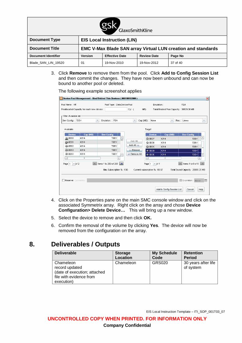
3. Click Remove to remove them from the pool. Click Add to Config Session List and then commit the changes. They have now been unbound and can now be bound to another pool or deleted.
The following example screenshot applies
4. Click on the Properties pane on the main SMC console window and click on the
associated Symmetrix array. Right click on the array and chose Device Configuration> Delete Device… This will bring up a new window.
5. Select the device to remove and then click OK. 6. Confirm the removal of the volume by clicking Yes. The device will now be
removed from the configuration on the array.
8. Deliverables / Outputs Deliverable Storage
Location My Schedule Code
Retention Period
Chameleon record updated (date of execution; attached file with evidence from execution)
Chameleon GRS020 30 years after life of system
Document Type EIS Local Instruction (LIN)
Document Title EMC V-Max Blade SAN array Virtual LUN creation and standards Document Identifier Version Effective Date Review Date Page No
Blade_SAN_LIN_19520 01 19-Nov-2010 19-Nov-2012 38 of 40
EIS Local Instruction Template – ITI_SOP_001T03_07
UNCONTROLLED COPY WHEN PRINTED. FOR INFORMATION ONLY Company Confidential
9. Training Requirements All personnel using this Local Instruction shall read and understand the content of this document and record this in their training records. All personnel using this LIN must have basic training of Network Appliance filers/storage arrays as this will assist in the understanding of setting up LUNs.
Training records for EIS permanent staff and EIS contracted resources are maintained in the myLearning system as detailed in ITI_SOP_3508 Training Records Management [2].
Creation of training records should be done by completing the myLearning module associated with this Local Instruction. If no myLearning module has been created for this Local Instruction, personnel should create a Personal Learning Activity in myLearning. Personnel working for a Third Party organisation shall maintain training records according to their Company’s standard approach and these shall be to a standard that meets GxP regulations and in compliance with GSK Contractual Requirements.
10. Glossary Term Definition
Bin file Pre-configured drive configurations used by EMC to setup the V-Max storage prior to useage
FCP Fibre Channel Protocol
LUN Logical Unit Number
NFS Network File System
SSH Secure Shell
TDAT Data Device
TDEV Thin Device
WWPN World Wide Port Name. A unique identifier in a Fibre Channel SAN (Storage Area Network).
11. References Item Document Identifier Document Title 1 ITI_SOP_3508 Training Records Management
Document Type EIS Local Instruction (LIN)
Document Title EMC V-Max Blade SAN array Virtual LUN creation and standards Document Identifier Version Effective Date Review Date Page No
Blade_SAN_LIN_19520 01 19-Nov-2010 19-Nov-2012 39 of 40
EIS Local Instruction Template – ITI_SOP_001T03_07
UNCONTROLLED COPY WHEN PRINTED. FOR INFORMATION ONLY Company Confidential
12. Revision Details Version number
Date Prepared By
Description
01 27-Oct-2010 David Beeker
1st authorised version of new Local Instruction.
Document Type EIS Local Instruction (LIN)
Document Title EMC V-Max Blade SAN array Virtual LUN creation and standards Document Identifier Version Effective Date Review Date Page No
Blade_SAN_LIN_19520 01 19-Nov-2010 19-Nov-2012 40 of 40
EIS Local Instruction Template – ITI_SOP_001T03_07
UNCONTROLLED COPY WHEN PRINTED. FOR INFORMATION ONLY Company Confidential
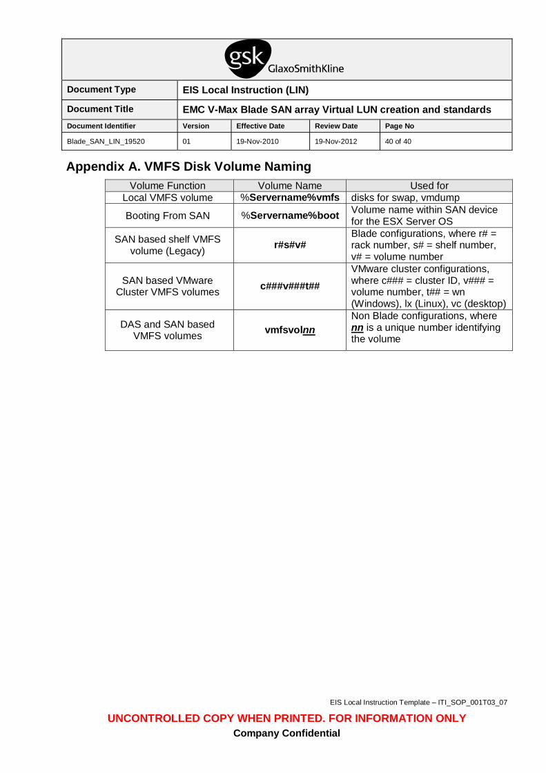
Appendix A. VMFS Disk Volume Naming Volume Function Volume Name Used for
Local VMFS volume %Servername%vmfs disks for swap, vmdump
Booting From SAN %Servername%boot Volume name within SAN device for the ESX Server OS
SAN based shelf VMFS volume (Legacy) r#s#v#
Blade configurations, where r# = rack number, s# = shelf number, v# = volume number
SAN based VMware Cluster VMFS volumes c###v###t##
VMware cluster configurations, where c### = cluster ID, v### = volume number, t## = wn (Windows), lx (Linux), vc (desktop)
DAS and SAN based VMFS volumes vmfsvolnn
Non Blade configurations, where nn is a unique number identifying the volume