Embed Size (px)
Citation preview
Software Version 4.1 Document Part Number 700-0100 R005
*700-0100*

This page intentionally left blank

About this GuideThe vMax Commander Installation and Configuration Guide is intended for anyone who needs to install and configure the vMax Commander software to manage video files. vMax Commander works with the following Seon DVRs:
• Explorer® DX-HD, DX12, TX8, MX-HD, MX4 Basic and Plus, Premier, EX8, EX4 series
• Trooper® TL4/TL2
Conventions Used
Abbreviations and Acronyms
CAUTIONCautions identify conditions or practices that could result in damage to the unit or other equipment.
Recommendation: These notes provide tips for optimum performance of the DVR system.
Important: These notes provide important information, which are not as serious as a Caution.
Acronym Definition
CAN Controller Area Network
DHCP Dynamic Host Configuration Protocol
DVR Digital Video Recorder
FPS Frames Per Second
GPS Global Positioning System
ICMP Internet Control Message Protocol
LAN Local Area Network
MAC Media Access Control
OLE Object Linking and Embedding
PC Personal Computer
SQL Structured Query Language
TCP Transmission Control Protocol
UNC Universal/Uniform Naming Convention
UTC Universal Time CoordinatedUTC is referenced to the atomic clock standard in Greenwich, England. The DVR location is a certain time difference from UTC time. For example, Eastern Standard Time is -5 hours from UTC time. Pacific Standard time is -8 hours from UTC time. Determine your time difference from UTC time and select this time.
700-0100 R005 iii

About this Guide
Finding Information OnlineYou can find more information about Seon Design Inc. as well as its products and services at www.seon.com.
iv 700-0100 R005
Contents
Chapter 1 Installation1.1. Introduction - - - - - - - - - - - - - - - - - - - - - - - - - - - - - - - - - - - - - - - - - - - - - - - - - - - - - - - - - - 1–1
1.2. DVR Firmware Compatibility - - - - - - - - - - - - - - - - - - - - - - - - - - - - - - - - - - - - - - - - - - - - - - 1–1
1.3. System Requirements- - - - - - - - - - - - - - - - - - - - - - - - - - - - - - - - - - - - - - - - - - - - - - - - - - - 1–2
1.3.1. Server Computer System Requirements - - - - - - - - - - - - - - - - - - - - - - - - - - - - - - - - - 1–2
1.3.2. Client Computer System Requirements - - - - - - - - - - - - - - - - - - - - - - - - - - - - - - - - - - 1–3
1.3.3. Network Component Settings - - - - - - - - - - - - - - - - - - - - - - - - - - - - - - - - - - - - - - - - - 1–3
1.4. Installing vMax Commander Software - - - - - - - - - - - - - - - - - - - - - - - - - - - - - - - - - - - - - - - 1–4
1.5. License Setup - - - - - - - - - - - - - - - - - - - - - - - - - - - - - - - - - - - - - - - - - - - - - - - - - - - - - - - 1–13
1.5.1. vMax Commander License Information - - - - - - - - - - - - - - - - - - - - - - - - - - - - - - - - - 1–131.5.1.1. USB License key - - - - - - - - - - - - - - - - - - - - - - - - - - - - - - - - - - - - - - - - - - - - - 1–141.5.1.2. Floating Network Licenses - - - - - - - - - - - - - - - - - - - - - - - - - - - - - - - - - - - - - - 1–141.5.1.3. Floating License Host Address Setup for Client - - - - - - - - - - - - - - - - - - - - - - - 1–16
1.6. Upgrading vMax Commander Software - - - - - - - - - - - - - - - - - - - - - - - - - - - - - - - - - - - - - 1–19
1.6.1. Database Backup - - - - - - - - - - - - - - - - - - - - - - - - - - - - - - - - - - - - - - - - - - - - - - - - - 1–20
1.7. Opening Windows Firewall Ports - - - - - - - - - - - - - - - - - - - - - - - - - - - - - - - - - - - - - - - - - - 1–21
1.7.1. Opening Ports in Windows XP and Vista - - - - - - - - - - - - - - - - - - - - - - - - - - - - - - - - 1–21
1.7.2. Opening Ports in Windows 7 - - - - - - - - - - - - - - - - - - - - - - - - - - - - - - - - - - - - - - - - - 1–23
1.8. Windows Power Settings- - - - - - - - - - - - - - - - - - - - - - - - - - - - - - - - - - - - - - - - - - - - - - - - 1–24
Chapter 2 Configuration2.1. System Configuration - - - - - - - - - - - - - - - - - - - - - - - - - - - - - - - - - - - - - - - - - - - - - - - - - - - 2–2
2.1.1. Typical System Configuration - - - - - - - - - - - - - - - - - - - - - - - - - - - - - - - - - - - - - - - - - 2–2
2.1.2. Configuring System IP Addresses - - - - - - - - - - - - - - - - - - - - - - - - - - - - - - - - - - - - - - 2–2
2.1.3. System Setup Recommendations - - - - - - - - - - - - - - - - - - - - - - - - - - - - - - - - - - - - - - 2–2
2.2. Device Detector and Auto Archiver Services - - - - - - - - - - - - - - - - - - - - - - - - - - - - - - - - - - - 2–3
2.3. Service Manager Configuration Settings - - - - - - - - - - - - - - - - - - - - - - - - - - - - - - - - - - - - - - 2–4
2.3.1. Archive Export Folder Setup - - - - - - - - - - - - - - - - - - - - - - - - - - - - - - - - - - - - - - - - - - 2–5
2.3.2. Broadcast IP Address - - - - - - - - - - - - - - - - - - - - - - - - - - - - - - - - - - - - - - - - - - - - - - - 2–6
2.3.3. MS SQL Server Database Setup - - - - - - - - - - - - - - - - - - - - - - - - - - - - - - - - - - - - - - - 2–6
2.3.4. Pre- and Post-Alarm Time Download Settings - - - - - - - - - - - - - - - - - - - - - - - - - - - - - 2–9
2.3.5. Maximum Parallel Archive Tasks - - - - - - - - - - - - - - - - - - - - - - - - - - - - - - - - - - - - - - - 2–9
2.3.6. Archive Download Retry Count - - - - - - - - - - - - - - - - - - - - - - - - - - - - - - - - - - - - - - - 2–10
2.3.7. Archive Low Resolution Video Stream (Supported in vMax View 3.5) - - - - - - - - - - - - 2–11
2.3.8. Start Device Detector and Auto Archiver Services - - - - - - - - - - - - - - - - - - - - - - - - - - 2–11
2.4. Logging in to vMax Commander - - - - - - - - - - - - - - - - - - - - - - - - - - - - - - - - - - - - - - - - - - 2–12
2.5. Log File Data - - - - - - - - - - - - - - - - - - - - - - - - - - - - - - - - - - - - - - - - - - - - - - - - - - - - - - - - 2–14
2.6. Email Notifications - - - - - - - - - - - - - - - - - - - - - - - - - - - - - - - - - - - - - - - - - - - - - - - - - - - - 2–15
2.7. Locations and Areas - - - - - - - - - - - - - - - - - - - - - - - - - - - - - - - - - - - - - - - - - - - - - - - - - - - 2–16
700-0100 R005 v
Contents
2.7.1. Locations - - - - - - - - - - - - - - - - - - - - - - - - - - - - - - - - - - - - - - - - - - - - - - - - - - - - - - 2–17
2.7.2. Areas - - - - - - - - - - - - - - - - - - - - - - - - - - - - - - - - - - - - - - - - - - - - - - - - - - - - - - - - - 2–18
2.8. DVR Setup - - - - - - - - - - - - - - - - - - - - - - - - - - - - - - - - - - - - - - - - - - - - - - - - - - - - - - - - - 2–19
2.9. DVR Configuration Download - - - - - - - - - - - - - - - - - - - - - - - - - - - - - - - - - - - - - - - - - - - - 2–21
2.9.1. DVR Configuration Best Practices - - - - - - - - - - - - - - - - - - - - - - - - - - - - - - - - - - - - - 2–21
2.9.2. Download a DVR Configuration - - - - - - - - - - - - - - - - - - - - - - - - - - - - - - - - - - - - - - 2–21
Chapter 3 User Permissions3.1. Create and Edit Users and Groups - - - - - - - - - - - - - - - - - - - - - - - - - - - - - - - - - - - - - - - - - 3–2
3.1.1. Add a New User - - - - - - - - - - - - - - - - - - - - - - - - - - - - - - - - - - - - - - - - - - - - - - - - - - 3–3
3.1.2. Automatic Login using Windows Login Settings - - - - - - - - - - - - - - - - - - - - - - - - - - - - 3–4
3.1.3. Edit a User - - - - - - - - - - - - - - - - - - - - - - - - - - - - - - - - - - - - - - - - - - - - - - - - - - - - - - 3–5
3.1.4. Remove a User - - - - - - - - - - - - - - - - - - - - - - - - - - - - - - - - - - - - - - - - - - - - - - - - - - - 3–5
3.1.5. Add a Domain User - - - - - - - - - - - - - - - - - - - - - - - - - - - - - - - - - - - - - - - - - - - - - - - - 3–6
3.1.6. Edit Permissions — Groups Tab - - - - - - - - - - - - - - - - - - - - - - - - - - - - - - - - - - - - - - - 3–6
3.1.7. Add a Group - - - - - - - - - - - - - - - - - - - - - - - - - - - - - - - - - - - - - - - - - - - - - - - - - - - - - 3–7
3.1.8. Edit a Group - - - - - - - - - - - - - - - - - - - - - - - - - - - - - - - - - - - - - - - - - - - - - - - - - - - - - 3–7
3.1.9. Remove a Group - - - - - - - - - - - - - - - - - - - - - - - - - - - - - - - - - - - - - - - - - - - - - - - - - - 3–7
3.1.10. Edit Permissions — Membership Tab - - - - - - - - - - - - - - - - - - - - - - - - - - - - - - - - - - 3–8
3.2. Assign User Rights - - - - - - - - - - - - - - - - - - - - - - - - - - - - - - - - - - - - - - - - - - - - - - - - - - - - 3–8
3.2.1. Assign Individual User Rights - - - - - - - - - - - - - - - - - - - - - - - - - - - - - - - - - - - - - - - - - 3–8
3.2.2. Rights Management in User Groups - - - - - - - - - - - - - - - - - - - - - - - - - - - - - - - - - - - - 3–9
3.2.3. Group Membership - - - - - - - - - - - - - - - - - - - - - - - - - - - - - - - - - - - - - - - - - - - - - - - 3–10
3.2.4. System Access Rights - - - - - - - - - - - - - - - - - - - - - - - - - - - - - - - - - - - - - - - - - - - - - 3–11
3.3. Assign Access Restrictions - - - - - - - - - - - - - - - - - - - - - - - - - - - - - - - - - - - - - - - - - - - - - - 3–12
3.3.1. Restricted Access Setup — Users Tab - - - - - - - - - - - - - - - - - - - - - - - - - - - - - - - - - 3–12
3.3.2. Restricted Access Setup — Groups Tab - - - - - - - - - - - - - - - - - - - - - - - - - - - - - - - - 3–12
Legal NoticeSeon Design Inc.® - - - - - - - - - - - - - - - - - - - - - - - - - - - - - - - - - - - - - - - - - - - - - - - - - - - - - - - - L–1
Contact Information - - - - - - - - - - - - - - - - - - - - - - - - - - - - - - - - - - - - - - - - - - - - - - - - - - - - - - - L–1
End-User License Agreement For Seon Design Inc. Software
End-User License Agreement - - - - - - - - - - - - - - - - - - - - - - - - - - - - - - - - - - - - - - - - - - - - - - - -W–1
vi 700-0100 R005

Chapter 1 Installation
Chapter 1 Installation
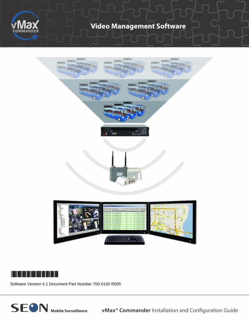
1.1. IntroductionvMax Commander is a video management software application for collecting and storing archive output from Seon Design digital video recorders.This chapter covers procedures for installing vMax Commander v4.1 software and configuring the application to suit your system requirements.The sections in this chapter cover the following topics:
DVR Firmware Compatibility, on page 1–1System Requirements, on page 1–2Network Component Settings, on page 1–3Installing vMax Commander Software, on page 1–4Upgrading vMax Commander Software, on page 1–19Database Backup, on page 1–20
For complete user instructions and procedures, see the vMax Commander User Guide (part 700-0120) at Help > Manual.
1.2. DVR Firmware CompatibilityvMax Commander 4.1 software is compatible with DVRs running the following firmware versions.
Ensure that your DVRs are running the correct firmware versions when using vMax Commander 4.1.
Important:The person installing and configuring vMax Commander must be a qualified IT specialist or system administrator.
DVR Type Firmware version
Explorer DX-HD 1.5
Explorer DX12 1.0.2
Explorer TX8 1.5
Explorer MX-HD 1.5
Explorer MX4 1.0.1
Trooper TL4/TL2 1.5
Explorer Premier 3.77
Explorer EX8 2.88
Explorer EX4 2.88
700-0100 R005 1–1

Chapter 1 Installation
1.3. System RequirementsFor vMax Commander software to perform optimally, use a server or client computer with the following minimum system requirements.
1.3.1. Server Computer System Requirements
Table 1-1 describes the minimum system requirements for the server computer.Table 1-1 Server PC Minimum System Requirements
Computer/Processor • Intel Core® I5 or greater for TL, MX4, MX-HD series DVRs• Intel Core® I7 or greater for TX8, DX12, DX-HD series DVRs• High performance video card with DirectX Ver. 10 or higher
support• 1280 × 1024 monitor resolution• 32 bit color quality• Sound card and speakers• USB 2.0• 2 x 1 GBit Ethernet adaptors
Operating Systems Windows Server 2008 R2, Windows® XP Service Pack 3, Windows Vista™, or Windows 7 (32-bit and 64-bit versions).
Memory 8GB RAM or more recommendedDisk Space 2TB of available hard-disk space (depending on the size of the fleet
video retention requirements)Drive CD/DVD writer drive and software (optional)Other Requirements Adobe® Acrobat® Reader to view the vMax Commander User
Guide and vMax View User Guide (available on the vMax View software CD or vMax with Tracking software CD)Internet access for remote access and supportMicrosoft Media Player, current versionMicrosoft .NET Ver. 3 or higher support
1–2 700-0100 R005

Chapter 1 Installation
1.3.2. Client Computer System Requirements
Table 1-2 provides the minimum system requirements for the client computer.
1.3.3. Network Component Settings
For best system operability, ensure that the following site network components have been properly configured to work with vMax Commander:
• DVR• Wi-Fi bridge• Wi-Fi access point• Computers
Table 1-2 Client PC Minimum System Requirements
Computer/Processor • Intel Core® I5 or greater for TL, MX4, MX-HD series DVRs• Intel Core® I7 or greater for TX8, DX12, DX-HD series DVRs• High performance video card with DirectX Ver. 10 or higher
support• 1280 × 1024 monitor resolution• 32 bit color quality• Sound card and speakers• USB 2.0• 1 GBit Ethernet adaptors
Operating Systems Windows® XP Service Pack 3, Windows Vista™, or Windows 7 (32-bit and 64-bit versions). Microsoft .NET Ver. 3 or higher support
Memory 2GB RAM or more recommendedDisk Space 10GB of available hard-disk space (depending on the amount of
video to be stored locally)Drive CD/DVD writer drive and software (optional)Other Requirements Adobe® Acrobat® Reader to view the vMax Commander User
Guide and vMax View User Guide (available on the vMax View software CD or vMax with Tracking software CD)Internet access for remote access and supportMicrosoft Media Player, current versionMicrosoft .NET Ver. 3 or higher support
700-0100 R005 1–3

Chapter 1 Installation
1.4. Installing vMax Commander SoftwareThe software should be installed by a system administrator with administrator rights at the computer for proper program installation. If upgrading the vMax Commander software, see Upgrading vMax Commander Software, on page 1–19, and follow the instructions there.To install the vMax Commander software from CD or downloaded .exe files:
1. Locate the vMax Commander installation files and place them together in a folder on your computer.
2. Close all programs on your computer.3. Double-click the Setupvn.n.n.n.exe file.
The InstallAware Wizard verifies the contents of the setup package.
When the Install Aware verification completes, the setup Wizard begins.
4. Follow the instructions on the Setup Wizard screens. For standard server installations, select the default features.
Note: If delivered separately, ensure that the vMax View installation files are in the same directory as the vMax Commander installation files.
Figure 1-1 Setup Verification Progress Bar
Figure 1-2 Welcome to vMax Commander Setup Window
1–4 700-0100 R005

Chapter 1 Installation
5. Click Next to display the License Agreement dialog shown in Figure 1-3.
6. Review the license agreement, select the lease agreement check box, and click Next to display the Select Features window shown in Figure 1-4.
7. For standard server installations, install all components.
Figure 1-3 License Agreement
Figure 1-4 Select Features
700-0100 R005 1–5

Chapter 1 Installation
Step 8 and 9 cover client software setup requirements.
8. In Select Features, enable and disable any features not required for this installation.
The feature icon changes to a red X indicating the feature and any sub features will not be installed, as shown in Figure 1-6.
Important:If you are installing the software as a client configuration, disable the Database, Auto Discover and Auto Archiving service options by clicking the component icon and, from the menu that appears, selecting Entire feature will be unavailable, as shown in Figure 1-5.
Figure 1-5 Disabling Installation of Components on Client Installation
Figure 1-6 Disabled Components on Client Installation
1–6 700-0100 R005

Chapter 1 Installation
9. To enable a feature for installing, click the icon and select Will be installed on local hard drive.
10. Click Next to display the Destination Folder dialog.11. Select the destination folder for installing the application shown in Figure 1-7.
12. Click Next to display the Ready to Install dialog shown in Figure 1-8.Figure 1-7 Destination Folder
Figure 1-8 Ready to Install
700-0100 R005 1–7

Chapter 1 Installation
13. If the Prerequisites dialog appears, as shown in Figure 1-9, your computer requires the listed applications to be installed. In most cases the wizard locates them and installs them and vMax Commander can proceed installing.
14. Click Next to continue. The setup wizard begins installing the software and momentarily displays the progress dialog shown in Figure 1-10.
Figure 1-9 Missing Prerequisites
Figure 1-10 Installing vMax Commander
1–8 700-0100 R005
Chapter 1 Installation
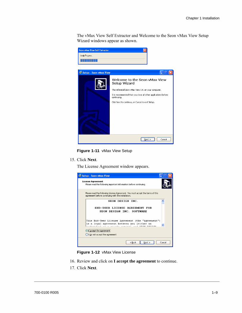
The vMax View Self Extractor and Welcome to the Seon vMax View Setup Wizard windows appear as shown.
15. Click Next.The License Agreement window appears.
16. Review and click on I accept the agreement to continue.17. Click Next.
Figure 1-11 vMax View Setup
Figure 1-12 vMax View License
700-0100 R005 1–9

Chapter 1 Installation
The Setup Destination Location window appears. Seon recommends allowing installation in the default directory.
18. Click Next.The Select Additional Task window appears with the Create a desktop icon check boxes selected (recommended).
19. Click Next.
Figure 1-13 vMax View Destination
Figure 1-14 vMax View Additional Tasks
1–10 700-0100 R005

Chapter 1 Installation
The Ready to Install window appears.
20. Verify the settings and click Install.vMax View installs on your computer.
Figure 1-15 vMax View Ready to Install
Figure 1-16 vMax View Installing
700-0100 R005 1–11
Chapter 1 Installation
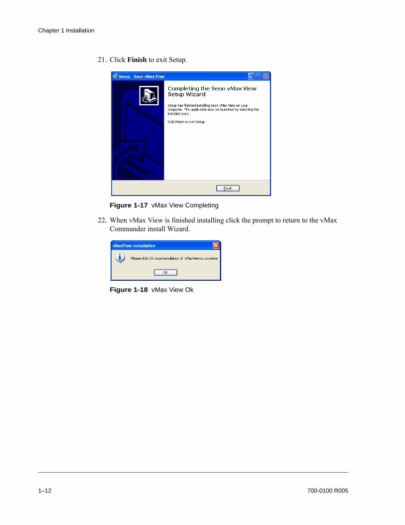
21. Click Finish to exit Setup.
22. When vMax View is finished installing click the prompt to return to the vMax Commander install Wizard.
Figure 1-17 vMax View Completing
Figure 1-18 vMax View Ok
1–12 700-0100 R005

Chapter 1 Installation
The vMax installer completes processes and then displays the vMax Commander Setup Complete dialog as shown in Figure 1-19. The Run vMax Commander now check box is automatically selected.
23. Click Finish to exit the installer.
The vMax Commander and vMax View desktop icons appear. The Seon Service Manager stoplight icon appears in the notification area of the Windows taskbar of the Server computer.The Login prompt appears. For login and user permission details, see Logging in to vMax Commander, on page 2–12 and Chapter 3 User Permissions, on page 3–1 for more information.For vMax View information, see the vMax View User Guide, 700-0137.
1.5. License SetupAfter logging in, if you see on the vMax Commander screen, it means that your computer does not have a vMax Commander license. To use the full version, install a USB license key or access a floating license. If a floating license is installed on the server but not detected by the client computer, see Floating License Host Address Setup for Client, on page 1–16.
1.5.1. vMax Commander License Information
Users require a licence to open vMax Commander on any computer where it is installed. Seon provides USB license keys and floating license options for customers. Without a license, users can only install a 90 day trial version.
Figure 1-19 Setup Completed
Note: On some computers, vMax Commander may need to reboot Windows now.
700-0100 R005 1–13

Chapter 1 Installation
1.5.1.1. USB License key
The USB license key enables vMax Commander to run on any computer by attaching the USB license key to the computer’s USB port.All computer systems with a USB 1.1 or higher USB port can use the USB license key. Drivers for the USB license key are installed when vMax Commander is installed.
1.5.1.2. Floating Network Licenses
For users that have a network connection to all workstations, the floating license option enables users to share a number of licenses. Usually the floating license will be installed on the vMax Commander video server computer.Upon launching, vMax Commander asks for a license from the floating license host server. If a license is available, vMax Commander opens for login. When a user exits vMax Commander, the license is made available to other network users.To configure the floating license host computer:
1. On the host video server computer, in the Windows system tray, click the CodeMeter icon to open the Codemeter Control Center.
2. In the CodeMeter Control center, click the WebAdmin button as shown in Figure 1-23.
Figure 1-20 CodeMeter Control Center
1–14 700-0100 R005

Chapter 1 Installation
The CodeMeter Web Admin site opens in a web browser. Internet access is not required.
3. Click the Configuration tab. In the tab, select the Run Network Server check box.
4. Click Apply to save and close the CodeMeter window.5. Log in to vMax Commander.
If appears on the screen, contact Seon Support.
Figure 1-21 CodeMeter Web Admin Home
Figure 1-22 CodeMeter Web Admin Server Configuration
700-0100 R005 1–15

Chapter 1 Installation
1.5.1.3. Floating License Host Address Setup for Client
Normally, a client computer on a network will automatically detect the floating license host computer, and the license will be available to run vMax Commander. Some network configurations do not automatically detect the floating license and the host server address must be manually entered in the client computer.To configure the floating license host computer address on the client computer:
1. Get the IP address or host name of the floating license host computer.2. On the computer with no license, in the Windows system tray, click the
CodeMeter icon to open the Codemeter Control Center.
3. In the CodeMeter Control center, click the WebAdmin button as shown in Figure 1-23.
Figure 1-23 CodeMeter Control Center
1–16 700-0100 R005

Chapter 1 Installation
The CodeMeter Web Admin site opens in a web browser. Internet access is not required.
4. Click the Configuration tab. In the tab, click Add.
5. In the Explorer User Prompt, enter the IP address of the floating license computer host. Click OK.
Figure 1-24 CodeMeter Web Admin Home
Figure 1-25 CodeMeter Web Admin Configuration
Figure 1-26 Explorer User Prompt
700-0100 R005 1–17

Chapter 1 Installation
6. In the Configuration tab, click Apply.
7. Log in and open vMax Commander.
If appears on the screen, contact Seon Support.
Figure 1-27 CodeMeter Web Admin Client Configuration Complete
1–18 700-0100 R005
Chapter 1 Installation
1.6. Upgrading vMax Commander Software
To upgrade vMax Commander on server and client computers:
1. On the server computer, record any custom Device Detector and Auto Archiver service settings.a) From the Windows desktop, right click My Computer and select Manage.b) In Computer Management, select Services and Applications, then Services.c) From the services list, click to open the Seon Auto Archiver and then the Seon
Device Detector. d) In the service Properties dialog, record the following settings:
• General tab: startup settings• Logon tab: logon settings• Recovery tab: response settings
2. On all computers, record any custom CodeMeter license settings, see Floating License Host Address Setup for Client, on page 1–16.
3. On the server computer, back up the database:• for MS Access databases, see Database Backup, on page 1–20• for SQL databases, use the SQL internal backup feature
4. On the server computer, stop the Device Detector and Auto Archiver services and exit Service Manager. See Device Detector and Auto Archiver Services, on page 2–3.
5. On all computers, uninstall the current vMax Commander version. • Windows Start > Programs > Seon > vMax Commander > Uninstall vMax
Commander.6. On all computers, upgrade to the new vMax Commander version. See Installing
vMax Commander Software, on page 1–4.7. On the server computer, update the database. Contact Seon Support if assistance is
required.8. On the server computer, update any custom Device Detector and Auto Archiver
service settings as described in step 1, and restart the Device Detector and Auto Archiver services.
9. On all computers, reset any custom CodeMeter license settings to the values recorded in step 2.
CAUTION: Contact Seon SupportUpgrading vMax Commander involves several system configuration and recording steps. The software upgrade should be installed by Seon or a qualified IT manager with administrator rights at the computer. Contact Seon Support if an upgrade is required.
700-0100 R005 1–19

Chapter 1 Installation
1.6.1. Database Backup
The Database Backup option from the System menu are only available when using the default Microsoft Access database.1. On the System menu, click on Database Backup to display the Select a Folder
dialog.2. Save a backup copy of the database to a folder in a local directory.3. Click OK to save.
A Backup Successful message appears when backup is completed.
Figure 1-28 Select a Folder
1–20 700-0100 R005

Chapter 1 Installation
1.7. Opening Windows Firewall PortsIf a firewall is enabled on your computer, you will have to open two UDP ports, 31500 and 31501, to properly enable the auto-downloading feature. (If you are using a third party firewall, refer to their product documentation.)The procedure for opening ports in Windows Firewall will depend on your Windows operating system.
1.7.1. Opening Ports in Windows XP and Vista
To open ports 31500 and 31501 on the Windows Firewall settings:
1. Open the Windows Control Panel and click the Security Center icon.
2. In the Windows Security Center, click Windows Firewall (in Windows Vista, click on Change Settings). See Figure 1-30.
Figure 1-29 Control Panel: Security Center
Security Center
Figure 1-30 Windows Security Center: Windows Firewall
700-0100 R005 1–21

Chapter 1 Installation
3. In the Windows Firewall dialog box, click the Exceptions tab. See Figure 1-31.
4. To open port 31500, click the Add Port… button.The Add a Port dialog box appears. See Figure 1-32.
5. In the Name field, enter a name (for example, vMax Commander 1).6. In the Port number field, enter Port number 31500.7. Click on UDP and then click OK.8. To open port 31501, click the Add Port… button.
Figure 1-31 Windows Firewall: Exceptions Tab
Figure 1-32 Add Port 31500
1–22 700-0100 R005

Chapter 1 Installation
The Add a Port dialog box appears. See Figure 1-33.
9. In the Name field, enter a name (for example, vMax Commander 2).10. In the Port number field, enter Port number 31501.11. Click on UDP and then click OK.12. To exit, click OK.
1.7.2. Opening Ports in Windows 7
To open ports 31500 and 31501 on the Windows Firewall settings:
1. In the Control Panel, depending on the selected view, click on either:• System and Security, and then click Windows Firewall.• Windows Firewall icon.
2. Add a Rule to open ports:a) Click on Advanced Settings (on left side of window).b) Click on Inbound Rules.c) Add a new rule by clicking on the New Rule button.d) Click to select Port, then click on the Next button.e) Click on the radio button to select UDP.f) Enter 31500-31501 in the text box for “Specific local ports.”g) Click on the Next button.h) Select “Allow the connection.”i) Click on the Next button.j) Select all items where it asks “When does this rule apply?”k) Click on the Next button.l) Enter a name for this rule, for example vMax Commander.m) Click on the Finish button.
3. Close all the windows opened for this configuration.
Figure 1-33 Add Port 31501
700-0100 R005 1–23

Chapter 1 Installation
1.8. Windows Power Settings
Set the power settings on the server computer (and client computers if they assist in auto-archiving) to Always On using the following procedures.To set the computer power settings to Always On in Windows 7:
1. Go to Control Panel > System and Security > Power Options.2. In Select a Power Plan, select Balanced.3. Click Change Plan Settings.4. In the Put the computer to sleep: drop down menu, choose Never.5. Click Save changes.
CAUTION: Data LossIt is important, particularly for the server computer, to change the Windows power settings to Always On. Otherwise, if the PC goes to sleep, auto archiving will not operate properly.
Figure 1-34 Windows 7 Power Settings Always On
1–24 700-0100 R005

Chapter 1 Installation
To set the computer power settings to Always On in Windows XP:
1. In the Control Panel, click Power Options.2. In the Power Options Properties window, select the Power Schemes tab.3. In the Power Schemes drop down menu, select Always On.4. In the Turn Off hard disks drop down menu, select Never.5. In the System Standby drop down menu, select Never.6. Click OK.
Figure 1-35 Windows XP Power Settings Always On
700-0100 R005 1–25

Chapter 1 Installation
1–26 700-0100 R005
Chapter 2 Configuration
Chapter 2 Configuration
Once the server and any client installations are complete and licenses and firewall ports are set up, there are some configuration steps required to run vMax Commander.This chapter covers setting up system IP addresses for communication, databases, and then setting up vMax Commander user permissions, DVRs, and other internal application settings.
System Configuration, on page 2–2Device Detector and Auto Archiver Services, on page 2–3Service Manager Configuration Settings, on page 2–4Logging in to vMax Commander, on page 2–12Log File Data, on page 2–14Email Notifications, on page 2–15Locations and Areas, on page 2–16DVR Setup, on page 2–19Locations and Areas, on page 2–16DVR Setup, on page 2–19DVR Configuration Download, on page 2–21
700-0100 R005 2–1

Chapter 2 Configuration
2.1. System Configuration
2.1.1. Typical System Configuration
Figure 2-1 shows a basic installation of a single standalone PC. This is the simplest system configuration.
More complex and scalable configurations can be implemented by contacting Seon Design for information on determining the system configuration for:
• Multi-client• Integrating with your Intranet
2.1.2. Configuring System IP Addresses
Make sure the IP address for the host computer and the DVR are set correctly. For a standard demonstration, configure the following component addresses as described in Table 2-1.
Please contact your network administrator or Seon Support if you are not sure about network settings.
2.1.3. System Setup Recommendations
If running antivirus software on the computer, set the software to accept *.arv and *.avr Seon DVR video files.
Figure 2-1 Basic Installation With a Standalone PC
Table 2-1 Component Configuration Addresses
Component IP Address Subnet Address
Laptop 172.24.1.1 255.255.0.0.Office Wi-fi access point 172.24.1.2 255.255.0.0.Bus Wi-fi bridge 172.24.2.1 255.255.0.0.DVR 172.24.2.2 255.255.0.0.
2–2 700-0100 R005

Chapter 2 Configuration
2.2. Device Detector and Auto Archiver ServicesWhen the computer starts up, the Device Detector and Auto Archiver services are running.Turn off the Device Detector and Auto Archiver services before making these changes:
• vMax Commander upgrades• database, Windows, or Service Manager configurations
Start them again after upgrades or configurations are done and before communicating with DVRs.To start or stop the Device Detector or Auto Archiver services:
1. Right click on the Service Manager system tray icon to display the menu and options as shown in Figure 2-3.
• To start, stop, or restart the Device Detector service, click Device Detector and change the setting.
• To start, stop, or restart the Auto Archive service, click Auto Archiver and change the setting.
The icon color indicates the status of the service as shown in Table 2-3.
Figure 2-2 Auto Archiver on
Figure 2-3 Device Detector off
Table 2-2 Start, Stop, or Restart conditions
Action ConditionStop Before vMax Commander uninstall, reinstall, or upgrade.Start After vMax Commander uninstall, reinstall, or upgrade.Restart After vMax Commander/Service Manager configuration update.
Table 2-3 Service Manager Icon
Icon Color StatusGreen icon: both the Device Detector and Auto Archiver services are running.
Yellow icon: only one service is running.
Red icon: neither service is running.
700-0100 R005 2–3

Chapter 2 Configuration
2.3. Service Manager Configuration SettingsIn the vMax Commander Service Manager configuration menus, complete the following configuration settings before connecting to DVRs:
• Archive Export Folder• Broadcast IP Address• MS SQL Server Database Setup (if using SQL)• Pre- and Post-Alarm download time• Maximum Parallel Archive Tasks• Archive Download Retry Count• Archive Low Resolution Video Stream
To configure Archive Download settings:
1. From the Windows system tray, right click the Service Manager icon .2. In the popup menu, select Configuration.
3. In the Configuration menu, select the General tab.
Figure 2-4 Service Manager Configuration
Figure 2-5 Archive Folder Location and Access Settings
2–4 700-0100 R005

Chapter 2 Configuration
2.3.1. Archive Export Folder Setup
4. Depending on whether the archives are downloading to a standalone computer or a network location, do one of the following:a) In the Default Archive Export Folder field, enter or browse to the archive
download location on the computer. ORb) If there are multiple users in a network that are accessing the video files, enter
or browse to the UNC network archive download location.
c) Modify the Auto Archiver service to log on as domain user as follows:• From the Windows desktop, right click My Computer and select Manage.• In Computer Management, select Services and Applications, then
Services.• From the services list, double click the Seon Auto Archiver to open the
properties dialog. • In the service Properties dialog, select the Log On tab• Select the This Account radio button and enter the username of the admin
user with read/write access to the downloaded archives. • Enter and confirm the admin user password.• Click OK to save and close the Windows service properties dialog.
Figure 2-6 Archive Folder Location and Access Settings
700-0100 R005 2–5

Chapter 2 Configuration
2.3.2. Broadcast IP Address
Set the broadcast IP address for the network to detect DVRs.5. Enter the Broadcast IP address.
2.3.3. MS SQL Server Database Setup
By default vMax Commander creates an MS Access database and connects to it during the server computer installation and no configuration is required. If an MS SQL database is installed and used on the server computer, you must create the Seon database and configure vMax Commander to use that database.
To add vMax Commander database to an MS SQL Server:
6. In Windows, open MS SQL Server Management Studio. 7. In MS SQL Server Management Studio, open the following file:
C:\Documents and Settings\All Users\Application Data\Seon\vMax Commander 4.0\Data\MS_SQL_CreateDatabase.sql.
8. In SQL Server Management Studio, click Execute to run the script. 9. When complete, close the SQL Server Management Studio.
Figure 2-7 Broadcast IP Address
2–6 700-0100 R005

Chapter 2 Configuration
10. In the vMax Commander Configuration menu, select the Database tab and click Edit Connection String.
11. In the Data Link Properties menu, select the Provider tab, and select Microsoft OLE DB Provider for SQL Server from the list.
Figure 2-8 Service Manager Configuration Database Tab
Figure 2-9 Service Manager Configuration
700-0100 R005 2–7

Chapter 2 Configuration
12. Click Next. In the Connection tab, select or enter the following:• server name• login information• database on the server (default is SeonSQL)
13. Click Test Connection to confirm the database setup.
14. Do one of the following:a) If the test connection failed, review all database settings and retry step 10.ORb) If the test connection succeeded, click Ok to close the window, click OK to
close the Data Link Properties menu, and click Ok again to close the Service Manager Configuration menu.
Figure 2-10 Service Manager Data Link Connection
Figure 2-11 Service Manager Database Connection Test
2–8 700-0100 R005

Chapter 2 Configuration
2.3.4. Pre- and Post-Alarm Time Download Settings
If necessary, change the settings for how much time before and after an alarm event is downloaded automatically from the DVR.15. In the Configuration menu, select the Auto Archive Download tab.
16. Set the Default Pre Alarm Time value in mm:ss (default: 01:00).17. Set the Default Post alarm time value in mm:ss (default: 05:00).
2.3.5. Maximum Parallel Archive Tasks
Set the number of archive downloads that vMax Commander can process at the same time. The number of archives vMax Commander can process is dependent on:
• server computer processing power and storage space• network bandwidth availability
18. In the Maximum Parallel Archive Tasks field, enter the desired value (default: 5).
Figure 2-12 Pre and Post Alarm Time Archived
Figure 2-13 Maximum Parallel Archives
700-0100 R005 2–9

Chapter 2 Configuration
2.3.6. Archive Download Retry Count
In the event of a Wi-fi network disconnection while an archive download is in progress, vMax Commander can retry downloading it. Set how many times the Auto Archive service will retry downloading an archive.19. In the Retry Count field, enter a desired value (default: 20).
20. Click Ok to save settings and close the Configuration window.
Figure 2-14 Archive Retry Count
2–10 700-0100 R005

Chapter 2 Configuration
2.3.7. Archive Low Resolution Video Stream (Supported in vMax View 3.5)
21. To archive the low resolution (or Record 2) video stream instead of the default high resolution (or Record) video stream for automatically generated archive jobs, select the Download Low Res. check box. This feature is only available for DX and MX series DVRs, and applies only to automatically generated archive jobs. Manual and Recurring archive jobs are configured independently. Use vMax View 3.5 to view low resolution archives.
2.3.8. Start Device Detector and Auto Archiver Services
After archive configuration settings are complete and before logging into vMax Commander and setting up DVRs, the Device detector and Auto Archiver services that were stopped need to be started.22. In Service Manager, start the Device Detector and Auto Archiver as described in
Device Detector and Auto Archiver Services, on page 2–3.
23. From the Windows icon tray, confirm that the Service Manager icon is green .
Improving Network Archive Download PerformanceArchive jobs with longer durations may take a significant amount of time to complete. Selecting the Download Low res. checkbox for longer video archive jobs will:• enable the archive to complete faster• save storage space on the disk• reduce demand on the wireless bandwidthLow resolution archives are supported in vMax View 3.5 and later versions.
700-0100 R005 2–11

Chapter 2 Configuration
2.4. Logging in to vMax CommanderAfter database and Service Manager setup is complete, the administrator can log in to set up vMax Commander users, DVRs, and internal application settings.
To login to vMax Commander:
1. Double click the vMax Commander icon on your computer desktop.2. In the login window that appears, as shown in Figure 2-15, enter the default
username and password to change configuration settings. The user name and password are case sensitive.
CAUTION: Password SecurityThe default user name and password is “admin”. For security purposes, Seon recommends that the user default login and system settings passwords should be changed. Seon is not responsible if the password is lost or forgotten. See Chapter 3 User Permissions, on page 3–1.
Figure 2-15 Login Screen
2–12 700-0100 R005

Chapter 2 Configuration
vMax Commander opens with the Explorer list area displaying a default DVR configuration as shown in Figure 2-16.
It may be convenient to have vMax Commander open from the desktop shortcut without having to log in each time. To configure vMax Commander to open using Windows login settings, see Automatic Login using Windows Login Settings, on page 3–4.
Figure 2-16 vMax Commander Application Window
Menu bar
Explorer list
Status bar
700-0100 R005 2–13

Chapter 2 Configuration
2.5. Log File DataThe action log tracks user activity, and can be used to provide an audit trail. Seon strongly recommends that this be enabled at each client workstation.For action log details, see the vMax Commander User Guide at Help > Manual.To enable the Action Log:
1. From the System menu, click Configuration and select the Explorer tab.2. Select the Log Extended Information check box.
3. Click Ok to save settings and close the Configuration menu.4. To see the action log, go to System > Actionlog
Figure 2-17 Log Extended Information
2–14 700-0100 R005

Chapter 2 Configuration
2.6. Email NotificationsvMax Commander can send system exception and Health Status Report emails to recipient(s). To enable email notifications:
1. From the System menu, click Configuration and select the Email tab.
2. Populate the fields and select options as required. Field definitions are described in Table 2-4:
3. Select the Heath Status Report Email check box.4. Enter the Subject and Sending Time.
Figure 2-18 Configuration > Email Tab
Table 2-4 Email Options
Menu item Description
SMTP Server Set the server name.SMTP Port Set the server port.SMTP Require Authentication
Select the check box if authentication is required .Clear the check box to not set the authentication.
Username/Password Set the username and password of the email account(s) to be used.from/to Set the sender and receiver email address(es).
Separate multiple addresses with ; .Test Settings Send a test email to the “to” email address to verify that the email
information is correct.Health Check Report Email
Select the check box to enable emailing the Health Status Report. For Health Status Report details, see the vMax Commander User Guide at Help > Manual.
Subject Set the email subject.Sending time Click the arrow to select the email send time for the Health Status
Report email.
700-0100 R005 2–15
Chapter 2 Configuration
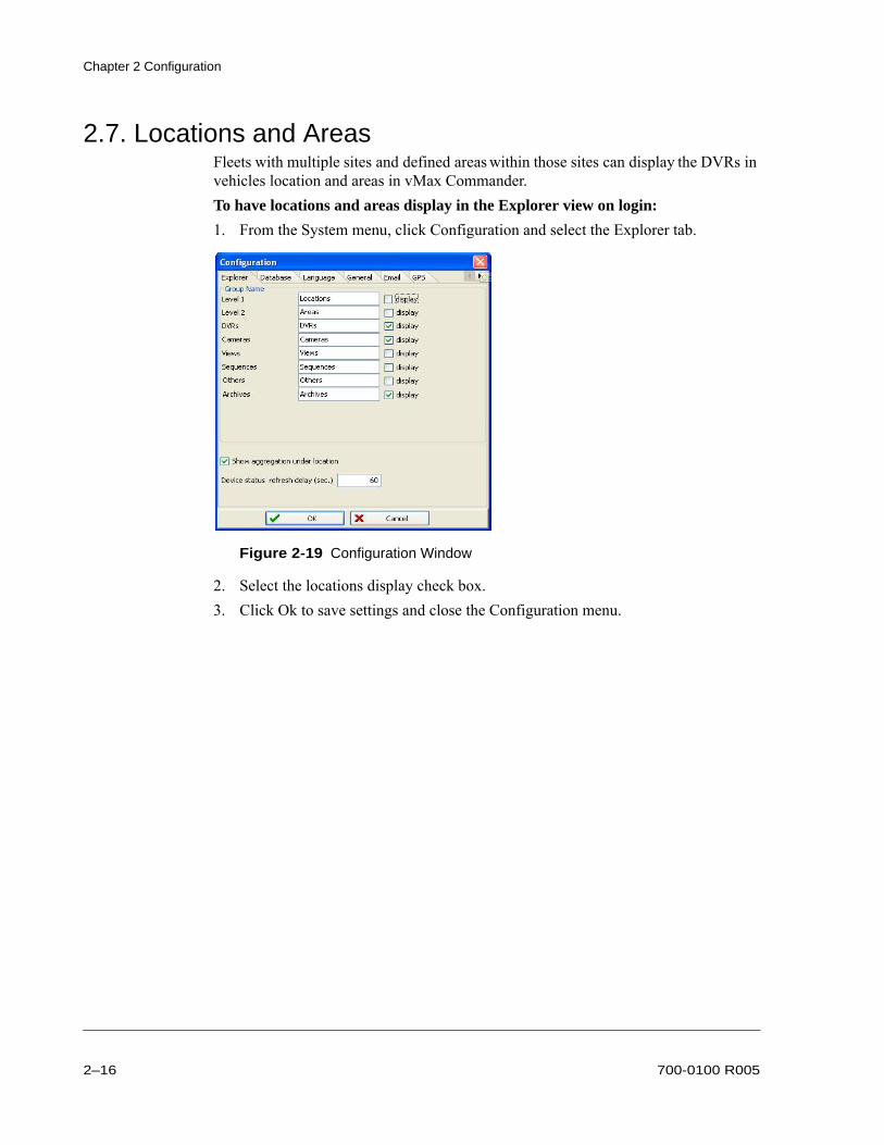
2.7. Locations and AreasFleets with multiple sites and defined areas within those sites can display the DVRs in vehicles location and areas in vMax Commander.To have locations and areas display in the Explorer view on login:
1. From the System menu, click Configuration and select the Explorer tab.
2. Select the locations display check box.3. Click Ok to save settings and close the Configuration menu.
Figure 2-19 Configuration Window
2–16 700-0100 R005

Chapter 2 Configuration
2.7.1. Locations
To create and edit locations:
1. From the Edit menu click Edit Locations.In the Location Setup window, add and delete buttons are available.
2. In the Location Setup window, add a location.3. In the Description field, enter a location name for the selected new location.
4. Click Close. Created Locations appear at the top folder level in the Explorer list. Locations contain areas, which contain all other view options and DVR components.
To delete a location:
1. Click Delete to display a confirmation dialog.2. Click Yes to delete the selected location OR click No to return to the Location
Setup window.3. Click Close to close the Location Setup window.
Figure 2-20 Archive Retry Count
700-0100 R005 2–17
Chapter 2 Configuration
2.7.2. Areas
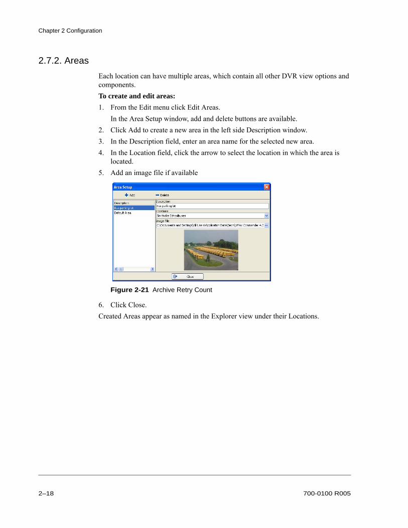
Each location can have multiple areas, which contain all other DVR view options and components.To create and edit areas:
1. From the Edit menu click Edit Areas.In the Area Setup window, add and delete buttons are available.
2. Click Add to create a new area in the left side Description window.3. In the Description field, enter an area name for the selected new area. 4. In the Location field, click the arrow to select the location in which the area is
located. 5. Add an image file if available
6. Click Close.Created Areas appear as named in the Explorer view under their Locations.
Figure 2-21 Archive Retry Count
2–18 700-0100 R005

Chapter 2 Configuration
2.8. DVR SetupUse the following procedure to set up a DVR in vMax Commander.1. In the vMax Commander Edit menu, click DVRs.
The DVR Setup dialog box appears. See Figure 2-22.
2. Click Add to add a new DVR to the Explorer view. Select the new DVR.3. In Description, enter the bus number for the DVR.4. If using Locations and Areas, select as required.5. On the Connection tab, with the DVR connected to the network, click the Device
Finder icon.
The Device Finder dialog box appears with a list of DVRs connected to the network. See Figure 2-24.
Figure 2-22 DVR Setup Dialog Box
Device Finder icon
Figure 2-23 Device Finder Dialog Box
700-0100 R005 2–19

Chapter 2 Configuration
6. Select a DVR from the list and click OK to close the Device Finder.7. If the DVR type is different from the default, a dialog box opens asking to modify
the settings to match the selected DVR. Click Yes to accept all new defaults.The Host, HTTP Port, CTRL port, DATA port, and MAC address are automatically populated.
8. In the DVR Setup dialog box, enter the network password of the DVR in the Password field.
9. Click the Auto Download tab and re-name the Alarm input titles to the alarm functions as shown in Table 2-24.
10. Clear check boxes for any unused camera channels.11. Download and save DVR configuration settings as described in DVR
Configuration Download, on page 2–21.12. Repeat these steps for all the vehicles with DVRs in the fleet.13. Click Close to save all changes and exit the DVR setup menu.
The Explorer list tree view displays the new DVRs.
CAUTION: Password SecurityThe default DVR password is “11111111”. For security purposes, Seon recommends that the user default login and system settings passwords should be changed. Seon is not responsible if the password is lost or forgotten. See Chapter 3 User Permissions, on page 3–1.
Figure 2-24 Auto Download tab
2–20 700-0100 R005

Chapter 2 Configuration
2.9. DVR Configuration DownloadSeon Design recommends that vMax Commander administrators download the configuration of each DVR to the database for reference.
2.9.1. DVR Configuration Best Practices
If you need to edit and update DVR configurations in vMax Commander, first download the current configuration from the DVR, then edit the settings as necessary, and upload and save the new configuration back to the DVR.
When updating DVR configurations remotely with vMax Commander, there is always the possibility that the configuration has been modified at the DVR, so it is highly recommended to always download the existing configuration before modifying it and uploading the new configuration. When Save is selected in vMax Commander after changes are made to the DVR configuration, the changes are saved in the database not the actual DVR.The configuration must be manually uploaded to the DVR when the DVR is on and connected to the network.Use the following procedures to ensure the configuration you edit is the latest from the DVR:
2.9.2. Download a DVR Configuration
1. In the DVR Setup window’s Description list, select a DVR that is live and on the system and click Configuration.If the DVR configuration has never been saved in vMax Commander, the following Information dialog appears.
Important: If the version on Commander and the DVR are not the same, communication and recording failures may occur. Be sure that the current configuration loaded on the DVR is the one that you are editing in vMax Commander.
;
Figure 2-25 Information Dialog
700-0100 R005 2–21

Chapter 2 Configuration
2. Click Ok in the Loading Default Configuration confirmation window.
3. In the DVR Configuration window on the upper icon row, click the Download DVR from Network icon to download the configuration from the DVR to vMax Commander.
4. In the Confirm dialog, click Yes.
5. In the DVR Configuration dialog, click Save to load the DVR configuration to the vMax Commander database.
6. In the Upload Confirm dialog, click No.
7. In the DVR Setup window, click Close.
For details on editing and uploading DVR configurations from vMax Commander back to the DVR, see the vMax Commander User Guide at Help > Manual.
;
Figure 2-26 DVR Configuration Dialog
;
Figure 2-27 Download Confirmation Dialog
;
Figure 2-28 Upload Confirmation Dialog
2–22 700-0100 R005

Chapter 3 User Permissions
Chapter 3 User Permissions
Once the application and DVR setups have been completed, users and their permissions can be set up.This chapter provides information for configuring the vMax Commander user permissions.
Create and Edit Users and Groups, on page 3–2Assign User Rights, on page 3–8Assign Access Restrictions, on page 3–12
vMax Commander default settings have three user levels: admin, supervisor, or user, as described in Table 3-1.Table 3-1 Software User Levels
User Name Password Level of user rights
admin admin The administrator has full access to all the menu items and can change the system configuration settings in the Edit and System menus. See the vMax Commander user guide 700-0120 for more details.
supervisor supervisor The supervisor can access the Program, View, Tools, System (Health Status Report, Archive Scheduler, Database maintenance, Database Backup only), and the Help menu. Supervisor has no configuration rights.
user user The user has viewing rights only and can access items in the Program menu.
700-0100 R005 3–1

Chapter 3 User Permissions
3.1. Create and Edit Users and GroupsThe Security Configuration menu option provides controls to set access restrictions for users and groups and to assign application permissions to users and groups.To edit user permissions:
1. On the System menu, point to Security Configuration, and then click Application.The Edit Permissions window appears as shown in Figure 3-1.In the Users list, “admin”, “supervisor”, and “user” are preset by default.
2. From this window do the following:• Add permissions to users from the Permission list.• Remove permissions from the users in the Users list.• Click Add User to open the Edit User dialog.• Remove users and permissions from the lists.
Figure 3-1 Edit Permissions
3–2 700-0100 R005

Chapter 3 User Permissions
3.1.1. Add a New User
To add a new user:
1. In the Edit Permissions window, click the Add User button. The Edit User dialog appears as shown in Figure 3-2.
2. Enter a user name, full name, and password. Re-enter the password to verify.3. Select a security question from the drop down menu. Enter the security answer.4. Click OK to save the settings. To add a Windows user:
1. In the Edit Permissions window, click on Add Windows User as shown in the lower right corner of Figure 3-1. The Import Windows User dialog appears with all the local Windows users listed as shown in Figure 3-3.
2. Select a user and click OK to display the Edit User window with the User name and Full Name populated (the same user name is used in both fields).
3. Click OK and the user appears in the Description list.4. Click Cancel to return to the Edit Permissions window.
Figure 3-2 Edit User Dialog
Figure 3-3 Import Windows User
700-0100 R005 3–3

Chapter 3 User Permissions
3.1.2. Automatic Login using Windows Login Settings
It may be convenient to automatically open vMax Commander from the desktop shortcut or Windows Start menu without having to log in each time.To configure vMax Commander to recognize Windows users:
1. In System menu > Security Configuration > Application > Users tab, add or edit a user to have the same username as the Windows user and no password. See Add a New User, on page 3–3.If a password is included in the user permissions, vMax Commander will prompt for it when opening.
2. In System menu > Security Configuration > Application > Membership tab, add a user to the required permission group (Administrator, Supervisor, or User) which has the permissions needed to perform the vMax Commander tasks. See Group Membership, on page 3–10.
3. From the System menu, choose Configuration.4. In the Configuration Window, select the General tab.5. In the Login Setup area, select the option, as shown in Figure 3-4.
6. Click Ok to save changes and close the menu.7. Exit vMax Commander.8. While logged in to Windows as the intended user, launch vMax Commander and
confirm settings.
Figure 3-4 Windows Username Without Password Check Selected
3–4 700-0100 R005

Chapter 3 User Permissions
3.1.3. Edit a User
To edit an existing user:
1. In the Edit Permissions window, click the user from the Users List.2. Click the Edit User button.
The Edit User dialog appears populated with user data, as shown in Figure 3-5.
3. Enter a user name, full name, and password. Re-enter the password to verify.4. Select a security question from the drop down menu. Enter the security answer.5. Click OK to save the settings.
3.1.4. Remove a User
To remove a user:
1. In the Edit Permissions window, click the user from the Users List.2. Click the Remove button to display a confirmation dialog.3. Click Yes to delete the user, or click No to cancel.
Figure 3-5 Edit User Dialog Populated
700-0100 R005 3–5
Chapter 3 User Permissions
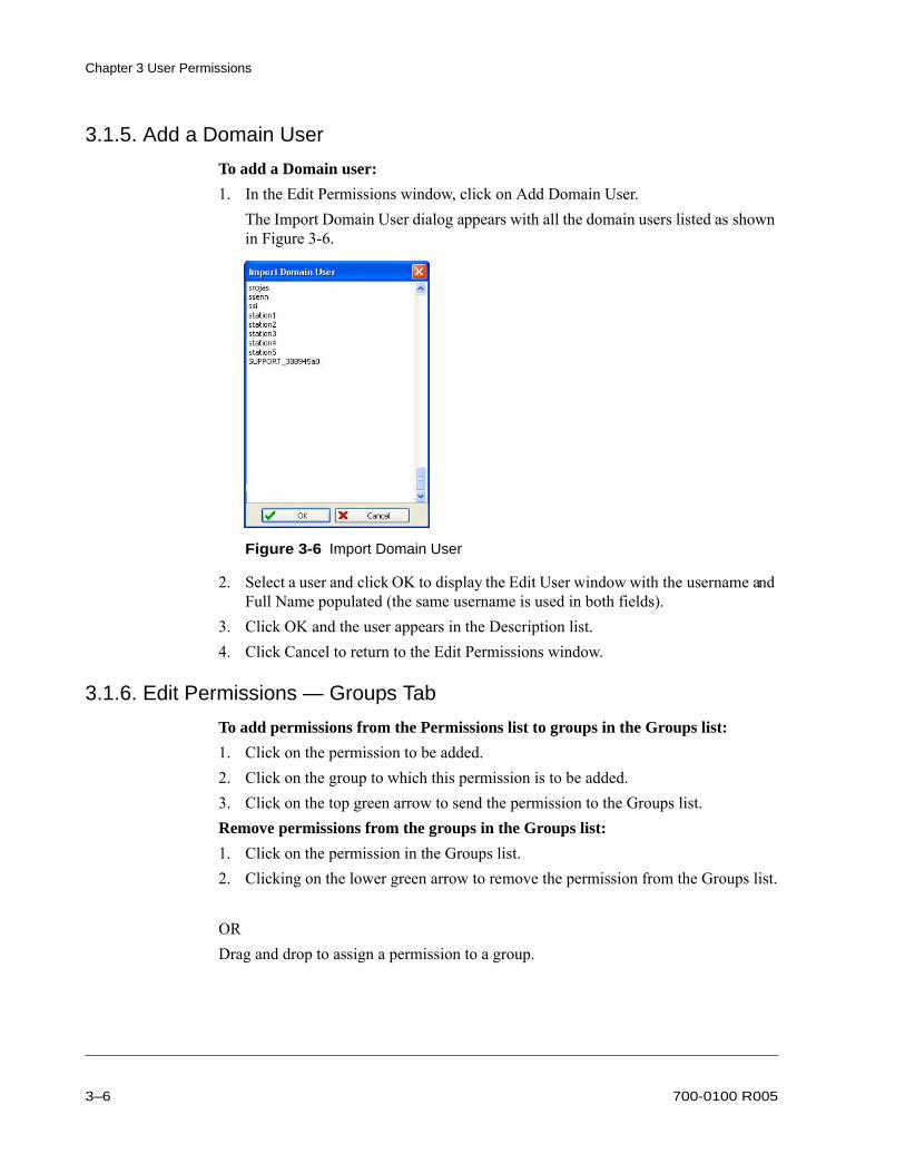
3.1.5. Add a Domain User
To add a Domain user:
1. In the Edit Permissions window, click on Add Domain User.The Import Domain User dialog appears with all the domain users listed as shown in Figure 3-6.
2. Select a user and click OK to display the Edit User window with the username and Full Name populated (the same username is used in both fields).
3. Click OK and the user appears in the Description list.4. Click Cancel to return to the Edit Permissions window.
3.1.6. Edit Permissions — Groups Tab
To add permissions from the Permissions list to groups in the Groups list:
1. Click on the permission to be added.2. Click on the group to which this permission is to be added.3. Click on the top green arrow to send the permission to the Groups list.Remove permissions from the groups in the Groups list:
1. Click on the permission in the Groups list.2. Clicking on the lower green arrow to remove the permission from the Groups list.
ORDrag and drop to assign a permission to a group.
Figure 3-6 Import Domain User
3–6 700-0100 R005

Chapter 3 User Permissions
3.1.7. Add a Group
To add a Group:
1. Click on Add Group… button.The Edit Group dialog appears as shown in Figure 3-7.
2. Enter a Group Name and Group Description.3. Click OK and the group appears in the Description list.4. Click Cancel to return to the Edit Permissions window.
3.1.8. Edit a Group
To edit a Group:
1. Click on the group in the Groups list.2. Click on Edit Group… button.
The Edit Group dialog appears as shown in Figure 3-8.
3. Enter a Group Name and Group Description.4. Click OK and the group appears in the Description list.5. Click Cancel to return to the Edit Permissions window.
3.1.9. Remove a Group
To remove a group:
1. Click the Group from the Group List.2. Click the Remove button to display a confirmation dialog.3. Click Yes to delete the group, or click No to cancel.
Figure 3-7 Edit Group
Figure 3-8 Edit Group Supervisor
700-0100 R005 3–7
Chapter 3 User Permissions
3.1.10. Edit Permissions — Membership Tab
Add users to the desired groups.Remove users from the groups in the Groups list.To remove groups, see Remove a Group, on page 3–7.
3.2. Assign User RightsThere are two ways to assign user rights in this menu, either by assigning individual user rights or by employing user groups.To add permissions from the Permissions list to users in the Users list:
1. Click on the permission to be added.2. Click on the user type to which this permission is to be added.3. Click on the top green arrow to send the permission to the Users list.To remove permissions from the users in the Users list:
1. Click on the permission in the Users list.2. Clicking on the lower green arrow to remove the permission from the Users list.
ORDrag and drop to assign a permission to a user.
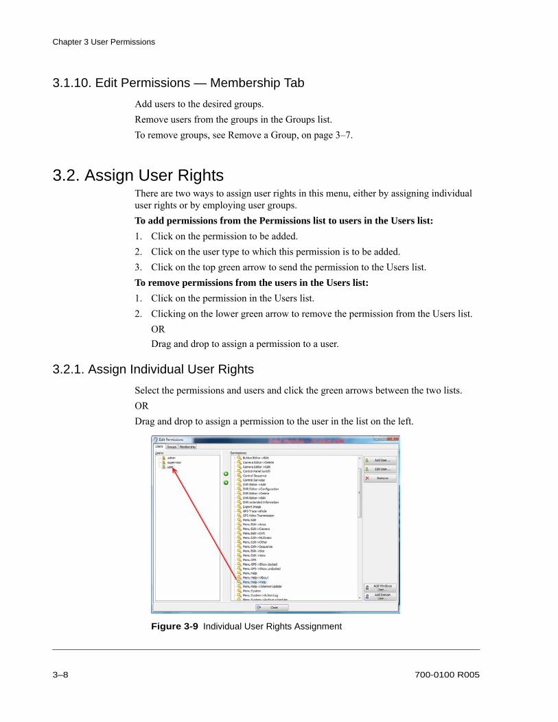
3.2.1. Assign Individual User Rights
Select the permissions and users and click the green arrows between the two lists.OR Drag and drop to assign a permission to the user in the list on the left.
Figure 3-9 Individual User Rights Assignment
3–8 700-0100 R005

Chapter 3 User Permissions
3.2.2. Rights Management in User Groups
In the default setting, three user groups are defined:• Administrator: allows access to all program functions.• Supervisor: allows access to all program functions except for configuration.• User: allows viewing only.Select the permissions and users and click the green arrows between the two lists to add or remove permissions.OR Drag and drop to assign a permission to the user type.
Figure 3-10 Groups Tab
700-0100 R005 3–9

Chapter 3 User Permissions
3.2.3. Group Membership
When working with user groups, users can be assigned to a user group.1. Select the Membership tab to set up group members.
2. Select the permissions and the users and click the green arrows between the two lists to add or remove permissions.OR Drag and drop to assign a permission to the user type.
Figure 3-11 Membership Tab
3–10 700-0100 R005

Chapter 3 User Permissions
3.2.4. System Access Rights
Assign specific system access rights to users and groups by selecting a user or group and using the green arrows to move access rights to the selected user or group.
Figure 3-12 Restricted Access Setup
700-0100 R005 3–11

Chapter 3 User Permissions
3.3. Assign Access RestrictionsTo configure security settings:
1. On the System menu, point to Security Configuration, and then click on Restricted Access.
2. In the Restricted Access Setup window, assign access restrictions to users and groups.
3.3.1. Restricted Access Setup — Users Tab
Add items from the Record list to users in the User list.Remove items from users in the Users list.Restricted items are listed on the left.
3.3.2. Restricted Access Setup — Groups Tab
Add items from the Record list to groups in the Groups list.Remove items from groups in the Groups list.Restricted items are listed on the left.
Figure 3-13 Restricted Access Setup Window
3–12 700-0100 R005

Legal NoticeSeon Design Inc.®Seon Design Inc. is a specialist in the design and manufacture of video surveillance systems for mobile applications. Seon has been the preferred solutions provider for the pupil transportation industry since 1999. Today, we are proud that our success in this area has made us the leading manufacturer of mobile video surveillance systems in North America.
Contact InformationSeon Design Inc., Unit 111, 3B Burbidge Street, Coquitlam, BC Canada V3K 7B2
Seon Design Inc. Trademarks
Seon Design Inc. holds the following trademarks:Rogue™, Rogue™ Plus, Explorer®, and Trooper® are registered trademarks of Seon Design Inc.“Seon Design” is a registered trademark of Seon Design Inc. The Seon logo ( ) is a registered trademark of Seon Design Inc.In this User Manual there are references to trademarks, registered trademarks, and product names not owned by Seon Design Inc. that are the property of their respective owners. They are used in this User Manual for identification purposes only.User Manual Revision
This is the R005 revision for this User Manual and is copyright, February 2013 of Seon Design Inc. All rights reserved.Exclusion of Liability
SEON DESIGN INC.:(a) MAKES NO REPRESENTATION, WARRANTY, GUARANTEE OR COVENANT, EXPRESS OR IMPLIED, AS TO THE ACCURACY, SUFFICIENCY OR SUITABILITY OF ANY TECHNICAL OR OTHER INFORMATION PROVIDED IN THIS USER MANUAL OR ANY OTHER USER OR OTHER MANUAL OR OTHER DOCUMENTATION PROVIDED BY SEON DESIGN INC. WITH RESPECT TO THE PRODUCT(S) DESCRIBED HEREIN, INCLUDING WITHOUT LIMITATION ANY DESCRIPTION OF GOODS OR SERVICES, SPECIFICATIONS, MODELS, DRAWINGS, OR DIAGRAMS.(b) DOES NOT ASSUME AND SHALL NOT BE SUBJECT TO AND DISCLAIMS ANY AND ALL RESPONSIBILITY AND/OR LIABILITY FOR LOSSES, DAMAGES, COSTS OR EXPENSES ARISING OUT OF BREACH OF CONTRACT OR OF WARRANTY, TORT (INCLUDING NEGLIGENCE AND STRICT LIABILITY) OR OTHERWISE, WHETHER SPECIAL, DIRECT, INDIRECT, CONSEQUENTIAL, INCIDENTAL, SPECIAL OR CONTINGENT, WHICH MIGHT ARISE OUT OF THE USE OF SUCH INFORMATION. THE USE OF ANY SUCH INFORMATION WILL BE ENTIRELY AT THE USER’S RISK; AND(c) EXPRESSLY DISCLOSES THAT IF THIS MANUAL IS WRITTEN IN ANY LANGUAGE OTHER THAN ENGLISH, THAT ALTHOUGH SEON DESIGN INC. HAS USED REASONABLE CARE TO MAINTAIN THE ACCURACY OF THE TRANSLATION FROM THE ENGLISH LANGUAGE, THE ACCURACY OF SUCH TRANSLATION IS NOT GUARANTEED OR WARRANTED BY SEON DESIGN INC. PLEASE REFER TO THE ENGLISH LANGUAGE VERSION OF THIS USER MANUAL FOR APPROVED SEON CONTENT. THE ENGLISH LANGUAGE VERSION IS AVAILABLE UPON REQUEST FROM THE SEON CUSTOMER SERVICE DEPARTMENT.Please refer to the Seon Design Inc. Product Warranty applicable to the Product(s) described in this User Manual which exclusively sets forth Seon Design Inc.’s entire liability arising from or in connection with such product(s) and their use and the exclusive remedies available for purchasers and users thereof.Document Part Number
This User Manual is valid for Seon Design Inc. Document Part Number 700-0100.Printed in Canada
Telephone 604.941.0880 Toll Free Telephone 1.877.630.7366Fax 604.941.0870 Toll Free Fax 1.866.664.3677Email [email protected] Web site www.seon.com
700-0100 R005 L–1

L
–2
End-User License Agreement For Seon Design Inc. SoftwareEnd-User License AgreementThis End-User License Agreement (the "Agreement") is a legal agreement between you (either an individual or a single entity) and SEONDESIGN INC. (“SEON”), for the use of one or more elements of the SEON proprietary software, that accompanies this Agreement (individuallyor collectively referred to as the "SOFTWARE"). The SOFTWARE may also include any updates and supplements to the original SOFTWAREprovided to you by SEON.BY INSTALLING, COPYING, OR USING THE SOFTWARE YOU AGREE TO BE BOUND BY THE TERMS OF THIS AGREEMENT IFYOU DO NOT AGREE, DO NOT INSTALL, COPY, OR USE THE SOFTWARE; YOU MAY RETURN IT TO YOUR PLACE OF PURCHASEFOR A FULL REFUND, IF APPLICABLE.This Agreement is made by and between you (the "LICENSEE") and SEON. WHEREAS:A. SEON has developed the SOFTWARE;B. The LICENSEE wishes to use the SOFTWARE in accordance with the terms set forth herein;NOW THEREFORE, in consideration of the foregoing and in consideration of the mutual promises, warranties, and covenants contained herein,the sufficiency of which is hereby acknowledged, the undersigned parties agree as follows:1. SOFTWARE License
1.1 SOFTWARE License. SEON grants to the LICENSEE a non-transferable, non-exclusive, limited license to:(a) install and use a copy of the SOFTWARE on one personal computer or other device; and (b) install an additional copy of the SOFTWARE on a second, portable device for the exclusive use of the primary user of the first copy of the
SOFTWARE.1.2 License Grant for Remote Assistance. The LICENSEE may permit any device to access and use its licensed copy of the SOFTWARE for
the sole purpose of providing the LICENSEE with technical support and maintenance services.1.3 Third Party Software. Any other software or materials accompanying this Agreement that is not owned by SEON and that is associated
with a separate end-user license agreement is licensed to the LICENSEE under the terms of that license agreement.1.4 License Grant for Documentation. The documentation the (“Documentation”) that accompanies the SOFTWARE is licensed for internal,
non-commercial reference purposes only.1.5 Reservation of Rights. SEON reserves all rights not explicitly granted herein. All licenses granted to the LICENSEE in this Agreement
herein are non-exclusive. Nothing in this Agreement shall be construed as limiting in any manner SEON’s marketing or distributionactivities or the licensing of the SOFTWARE by the SEON to any third party. The SOFTWARE is licensed, not sold.
1.6 Restrictions. The License granted hereby is for the SOFTWARE in object code form only and, subject to Section 2.4, the LICENSEE shallnot:(a) use, copy, republish or distribute the SOFTWARE, or cause or permit any person to use, copy, republish or distribute the SOFTWARE,
except as expressly permitted under this Agreement;(b) loan, sell, rent, lease, sublicense, grant a security interest in, republish, distribute, loan or otherwise transfer rights to the SOFTWARE, in
whole or in part;(c) directly or indirectly attempt in any way to derive the source code, content, structure, sequence or organization of all or any portion of the
SOFTWARE, nor will attempt to modify, port, reverse engineer, de-compile, or translate the SOFTWARE, or to create derivative worksthereof;
(d) remove any proprietary notices or labels from the SOFTWARE.1.7 Back Up Copy. The LICENSEE is authorized to make one copy for archive purpose of the SOFTWARE, in non-printed machine language
object code form only.1.8 LICENSEE Indemnification. The LICENSEE shall indemnify, defend and hold SEON and its affiliates, officers, directors, agents and
employees harmless from any losses, liabilities, damages, costs or expenses, including reasonable attorney’s fees, arising out of any breachby the LICENSEE of its obligations under this Agreement or any unauthorized alteration, modification, adjustment or enhancement made bythe LICENSEE to the SOFTWARE or the Documentation.
1.9 Trademarks. The LICENSEE acknowledges and agrees that this Agreement does not grant the LICENSEE any rights to use any trademarksor trade names of SEON or their licensors. All such marks shall remain the property of the respective owner.
700-0100 R005 EULA–1

End-User License Agreement For Seon Design Inc. Software
2. SEON Warranty
2.1 Warranty. SEON represents and warrants to the LICENSEE that for a period of ninety (90) days from the receipt of the SOFTWARE by theLICENSEE the tangible media on which the SOFTWARE is recorded will be free from defects in materials and workmanship under normaluse.
2.2 Remedies. SEON’s entire liability and the exclusive remedy of the LICENSEE for any breach of the limited warranty set out in Section 2.1shall be replacement upon receipt by SEON of the defective media not meeting SEON’s limited warranty. SEON will have no responsibilityto replace media damaged by accident, abuse or misapplication.
3. Disclaimers, Warranties and Limitation of Liability
3.1 NO WARRANTIES. SEON DISCLAIMS ANY AND ALL WARRANTIES WITH RESPECT TO THE SOFTWARE, EITHER EXPRESSOR IMPLIED, INCLUDING, BUT NOT LIMITED TO, IMPLIED WARRANTIES OF MERCHANTABILITY AND FITNESS FOR APARTICULAR PURPOSE AND ANY OTHER EXPRESS WARRANTIES OR SIMILAR OBLIGATIONS (IF ANY) CREATED BY ANYADVERTISING, DOCUMENTATION, PACKAGING OR OTHER COMMUNICATIONS. THE LICENSEE ACKNOWLEDGES THATIT HAS NOT RELIED ON ANY WARRANTY MADE BY SEON. THE SOFTWARE IS PROVIDED ON AN “AS IS WITH ALLFAULTS” BASIS WITH NO WARRANTY, EXPRESS OR IMPLIED AND SEON HAS NO OBLIGATION TO PROVIDEMAINTENANCE, SUPPORT, UPDATES, ENHANCEMENTS OR MODIFICATIONS WITH RESPECT TO THE SOFTWARE TO THELICENSEE. THERE IS NO WARRANTY OR CONDITION OF TITLE, QUIET ENJOYMENT, QUIET POSSESSION,CORRESPONDENCE TO DESCRIPTION OR NON-INFRINGEMENT WITH REGARD TO THE SOFTWARE.
3.2 EXCLUSION OF OTHER WARRANTIES. THE LICENSEE ACKNOWLEDGES THAT THE SOFTWARE MAY CONTAIN ERRORSAND MAY BE INCOMPLETE OR CONTAIN INACCURACIES AND THAT EXCEPT AS EXPRESSLY SET OUT IN SECTION 2.1SEON DOES NOT WARRANT THAT THE FUNCTIONS CONTAINED IN THE SOFTWARE WILL MEET THE REQUIREMENTS OFTHE LICENSEE, THAT THE OPERATION OF THE SOFTWARE WILL BE UNINTERRUPTED OR ERROR-FREE OR THATDEFECTS IN THE SOFTWARE WILL BE CORRECTED. FURTHER, SEON DOES NOT WARRANT OR MAKE ANYREPRESENTATIONS REGARDING THE USE OR THE RESULTS OF THE USE OF THE SOFTWARE IN TERMS OF ITSCORRECTNESS, ACCURACY, RELIABILITY OR OTHERWISE.
3.3 LIMITATION OF LIABILITY. IN NO EVENT SHALL SEON BE LIABLE FOR ANY DAMAGES SUFFERED OR INCURRED BYTHE LICENSEE OR ANY OTHER PERSON OR ENTITY INCLUDING, WITHOUT LIMITATION, ANY SPECIAL, PUNITIVE,INCIDENTAL, INDIRECT, DIRECT, PUNITIVE OR CONSEQUENTIAL DAMAGES WHATSOEVER (INCLUDING, WITHOUTLIMITATION, DAMAGES FOR LOSS OF BUSINESS PROFITS, LOSS OF REVENUE, BUSINESS INTERRUPTION, LOSS OFBUSINESS INFORMATION, FOR PERSONAL INJURY, FOR LOSS OF PRIVACY, FOR FAILURE TO MEET ANY DUTYINCLUDING OF GOOD FAITH OR OF REASONABLE CARE, FOR NEGLIGENCE, OR ANY OTHER PECUNIARY LOSSWHATSOVER) ARISING OUT OF THE USE OF OR INABILITY TO USE THE SOFTWARE, EVEN IF SEON HAS BEEN ADVISEDOF THE POSSIBILITY OF SUCH DAMAGES.
4. No Exclusivity
4.1 No Exclusivity. Nothing in this Agreement nor the license of the SOFTWARE shall constitute or imply any promise to or intention to makeany purchase of products or services by either party or its affiliates or any commitment by either party or its affiliates with respect to thepresent or future marketing of any product or service or any commitment to enter into any other business relationship.
5. Termination. 5.1 Termination. Without prejudice to any other rights, SEON may terminate this Agreement if the LICENSEE fails to comply with the terms
and conditions of this Agreement. In such event, The LICENSEE shall destroy all copies of the SOFTWARE and all of its component parts.6. Restricted Rights. 6.1 Restricted Rights. The SOFTWARE was developed at private expense, is commercial, and is published and copyrighted. The SOFTWARE
may be transferred to the U.S. government only with the prior written consent of an officer of Licensor and solely with "Restricted Rights" asthat term is defined in FAR 52.227-19(c)(2) (or DFAR 252.227-202.32 (c)(1) if the transfer is to a defence-related agency) or subsequentcitation. If LICENSEE is an agency of the United States government or licensing the SOFTWARE for operation on behalf of the UnitedStates government, the SOFTWARE is licensed to LICENSEE with rights no greater than those set forth in Federal Acquisition Regulation52.227-19(c)(2) [or DFAR 252.227-7202.32 (c)(1) if the LICENSEE is a defence-related agency] or subsequent citation.
7. LICENSEE Representations
7.1 Binding Effect. By accepting delivery of the SOFTWARE, copying, accessing or otherwise using t he SOFTWARE, t he LICENSEErepresents and warrants to SEON that the LICENSEE has all requisite power and authority to enter into this Agreement and has all necessarypower and authority to perform the obligations of the LICENSEE as set out herein.
8. General
8.1 Assignment. The LICENSEE may not assign, sublicense, transfer or encumber this Agreement without the prior written consent of SEON.Subject to the limitations set forth in this Agreement, this Agreement will inure to the benefit of and be binding upon the parties, theirsuccessors and permitted assigns.
8.2 Separation of Components. The SOFTWARE is licensed as a single product. Its component parts may not be separated for use license,distribution or replacement by the LICENSEE.
EULA–2 700-0100 R005

9. Governing Law, Jurisdiction and Venue
9.1 Provisions Applicable to American LICENSEES. SEON is physically located within the Province of British Columbia, Canada. For thoseLICENSEES whose mailing address is in the United States, this agreement shall be governed by and construed in accordance with theinternal and domestic laws of the State of WASHINGTON without giving effect to the conflict of laws rules thereof. The Superior Court ofWashington for Whatcom County and U.S. District Court for the Western District of Washington (“the U.S. Closed Courts”) shall haveexclusive jurisdiction to hear and make any judicial determination on any issue arising with respect to this Agreement. We expressly excludethe UN Convention on Contracts for the International Sale of Goods as amended, replaced or re-enacted from time to time.
9.2 Provisions Applicable to Other LICENSEES. SEON is physically loc ated within the Province of British Columb ia, Canada. For thoseLICENSEES whose mailing address is NOT in the United States, this Agreement will be governed by and construed in accordance with thelaws of the Province of British Columbia and the laws of Canada applicable therein. The parties agree that the Courts of the Province ofBritish Columbia shall have exclusive jurisdiction to hear and make any judicial determination on any issue arising with respect to thisAgreement. We expressly exclude the UN Convention on Contracts for the International Sale of Goods as amended, replaced or re-enactedfrom time to time. We have required that this Agreement and all documents relating thereto be drawn-up in English. NOUS avons demandeque cette convention ainsi que tous les documents qui s'y rattachent soient rediges en anglais.
10. Entire Agreement
10.1 Entire Agreement. This Agreement constitutes the entire understanding between the par ties hereto and supe rsedes all previouscommunications, representations and understandings, oral or written, between the parties, with respect to the subject matter of thisAgreement.
700-0100 R005 W–3

End-User License Agreement For Seon Design Inc. Software
EULA–4 700-0100 R005

This page intentionally left blank

Seon Design Inc.Unit 111, 3B Burbidge StreetCoquitlam, BC Canada V3K 7B2
TelephoneToll Free Telephone
604.941.08801.877.630.7366
Fax Toll Free Fax
604.941.08701.866.664.3677
Email [email protected]
Web site www.seon.com
700-0100 R005 Printed in Canada