Embed Size (px)
Citation preview

Contents
1 Introduction 5
1.1 Available Literature 5
1.2 Manual and Software Version 5
1.3 Abbreviations 5
1.4 Definitions 6
1.5 Power Factor 8
2 Safety and Conformity 9
2.1 Safety 9
2.2 Disposal Instruction 10
2.3 Approvals 10
2.4 CE Labeling 10
2.6 Aggressive Environments 11
2.7 Vibration and Shock 12
2.8 Advantages 12
3 Product Overview 18
3.1 Control Structures 18
3.1.1 Control Structure Open Loop 18
3.1.2 Local (Hand On) and Remote (Auto On) Control 18
3.1.3 Control Structure Closed Loop 18
3.1.4 Reference Handling 20
3.2 General Aspects of EMC 21
3.2.1 General Aspects of EMC Emissions 21
3.2.2 Emission Requirements 22
3.2.3 EMC Test Results (Emission) 22
3.2.4 Harmonics Emission Requirements 23
3.2.5 Immunity Requirements 23
3.3 Galvanic Isolation (PELV) 23
3.4 Ground Leakage Current 24
3.5 Extreme Running Conditions 24
3.5.1 Motor Thermal Protection 24
4 Selection 26
4.1 Options and Accessories 26
4.1.1 Local Control Panel (LCP) 26
4.1.2 Remote Mounting Kit for LCP 26
4.1.3 FC 51 Remote Mounting Kit Mounting Instruction 26
4.1.4 IP21/TYPE 1 Enclosure Kit 28
4.1.5 Type 1 (NEMA) 28
Contents Design Guide
MG02K402 Danfoss A/S © 01/2016 All rights reserved. 1
4.1.6 Decoupling Plate 28
4.1.7 FC 51 Type 1 Kit Mounting Instruction for M1, M2 and M3 29
4.1.8 FC 51 Type 1 Kit Mounting Instruction for M4 and M5 29
4.1.9 FC 51 IP21 Kit Mounting Instruction 30
4.1.10 FC 51 Decoupling Plate Mounting Instruction for M1 and M2 31
4.1.11 FC 51 Decoupling Plate Mounting Instruction for M3 31
4.1.12 FC 51 Decoupling Plate Mounting Instruction for M4 and M5 32
4.1.13 FC 51 DIN Rail Kit Mounting Instruction 33
4.1.14 Line Filter MCC 107 Installation Instructions 33
4.1.15 Mounting 34
4.1.16 Wiring 34
4.1.17 Dimensions 35
4.2 Special Conditions 36
4.2.1 Purpose of Derating 36
4.2.2 Derating for Ambient Temperature 36
4.2.3 Derating for Low Air Pressure 37
4.2.4 Automatic Adaptations to Ensure Performance 37
4.2.5 Derating for Running at Low Speed 37
5 How to Order 38
5.1 Drive Configurator 38
5.2 FC Identification 38
5.3 Type Code 39
5.4 Ordering Numbers 40
5.5 Options 40
6 How to Install 42
6.1 Before Starting 42
6.2 Side-by-Side Installation 42
6.3 Before Commencing Repair Work 42
6.4 Mechanical Dimensions 42
6.5 Electrical Installation in General 43
6.6 Fuses 44
6.7 Mains Connection 45
6.8 Motor Connection 45
6.9 Use of EMC-Correct Cables 48
6.10 Grounding of Shielded/Armored Control Cables 49
6.11 Residual Current Device 49
6.12 Electrical Overview 50
6.12.1 Power Circuit - Overview 50
6.13 Electrical Installation and Control Cables 51
Contents VLT® Micro Drive FC 51
2 Danfoss A/S © 01/2016 All rights reserved. MG02K402
6.14 Control Terminals 51
6.14.1 Access to Control Terminals 51
6.14.2 Connecting to Control Terminals 52
6.15 Switches 52
6.16 Final Set-Up and Test 52
6.17 Parallel Connection of Motors 54
6.18 Motor Installation 55
6.19 Installation of Misc. Connections 55
6.20 Safety 56
6.20.1 High-voltage Test 56
6.20.2 Safety Ground Connection 56
7 Programming 57
7.1 How to Programme 57
7.1.2 Programming with the LCP 11 or LCP 12 57
7.2 Status Menu 58
7.3 Quick Menu 59
7.4 Quick Menu Parameters 59
7.5 Main Menu 63
7.6 Quick Transfer of Parameter Settings between Multiple Frequency Converters 63
7.7 Readout and Programming of Indexed Parameters 63
7.8 Initialize the Frequency Converter to Default Settings in two Ways 63
8 RS485 Installation and Set-up 65
8.1 RS485 Installation and Set-up 65
8.1.1 Overview 65
8.1.2 Network Connection 65
8.1.3 Frequency Converter Hardware Set-up 65
8.1.4 EMC Precautions 66
8.2 FC Protocol Overview 66
8.3 Network Configuration 67
8.4 FC Protocol Message Framing Structure 67
8.4.1 Content of a Character (byte) 67
8.4.2 Telegram Structure 67
8.4.3 Telegram Length (LGE) 68
8.4.4 Frequency Converter Address (ADR) 68
8.4.5 Data Control Byte (BCC) 68
8.4.6 The Data Field 68
8.4.7 The PKE Field 69
8.4.8 Parameter Number (PNU) 70
8.4.9 Index (IND) 70
Contents Design Guide
MG02K402 Danfoss A/S © 01/2016 All rights reserved. 3
8.4.10 Parameter Value (PWE) 70
8.4.11 Data Types Supported by the Frequency Converter 70
8.4.12 Conversion 70
8.4.13 Process Words (PCD) 70
8.5 Examples 71
8.6 Modbus RTU Overview 71
8.6.1 Prerequisite Knowledge 71
8.6.2 What the User Should Already Know 71
8.6.3 Overview 71
8.6.4 Frequency Converter with Modbus RTU 72
8.7 Network Configuration 72
8.8 Modbus RTU Message Framing Structure 72
8.8.1 Introduction 72
8.8.2 Modbus RTU Telegram Structure 73
8.8.3 Start/Stop Field 73
8.8.4 Address Field 73
8.8.6 Data Field 73
8.8.7 CRC Check Field 73
8.8.8 Coil Register Addressing 74
8.8.9 How to Control the Frequency Converter 75
8.8.10 Function Codes Supported by Modbus RTU 75
8.8.11 Modbus Exception Codes 76
8.9 How to Access Parameters 76
8.9.1 Parameter Handling 76
8.9.2 Storage of Data 76
8.10 Examples 77
8.10.1 Read Coil Status (01 hex) 77
8.10.2 Force/Write Single Coil (05 hex) 77
8.10.3 Force/Write Multiple Coils (0F hex) 78
8.10.4 Read Holding Registers (03 hex) 78
8.10.5 Preset Single Register (06 hex) 79
8.10.6 Preset Multiple Registers (10 hex) 79
8.11 FC Drive Control Profile 80
8.11.1 Control Word According to FC Profile 80
8.11.2 Status Word According to FC Profile (STW) 81
8.11.3 Bus Speed Reference Value 83
9 Specifications 84
Index 91
Contents VLT® Micro Drive FC 51
4 Danfoss A/S © 01/2016 All rights reserved. MG02K402
1 Introduction
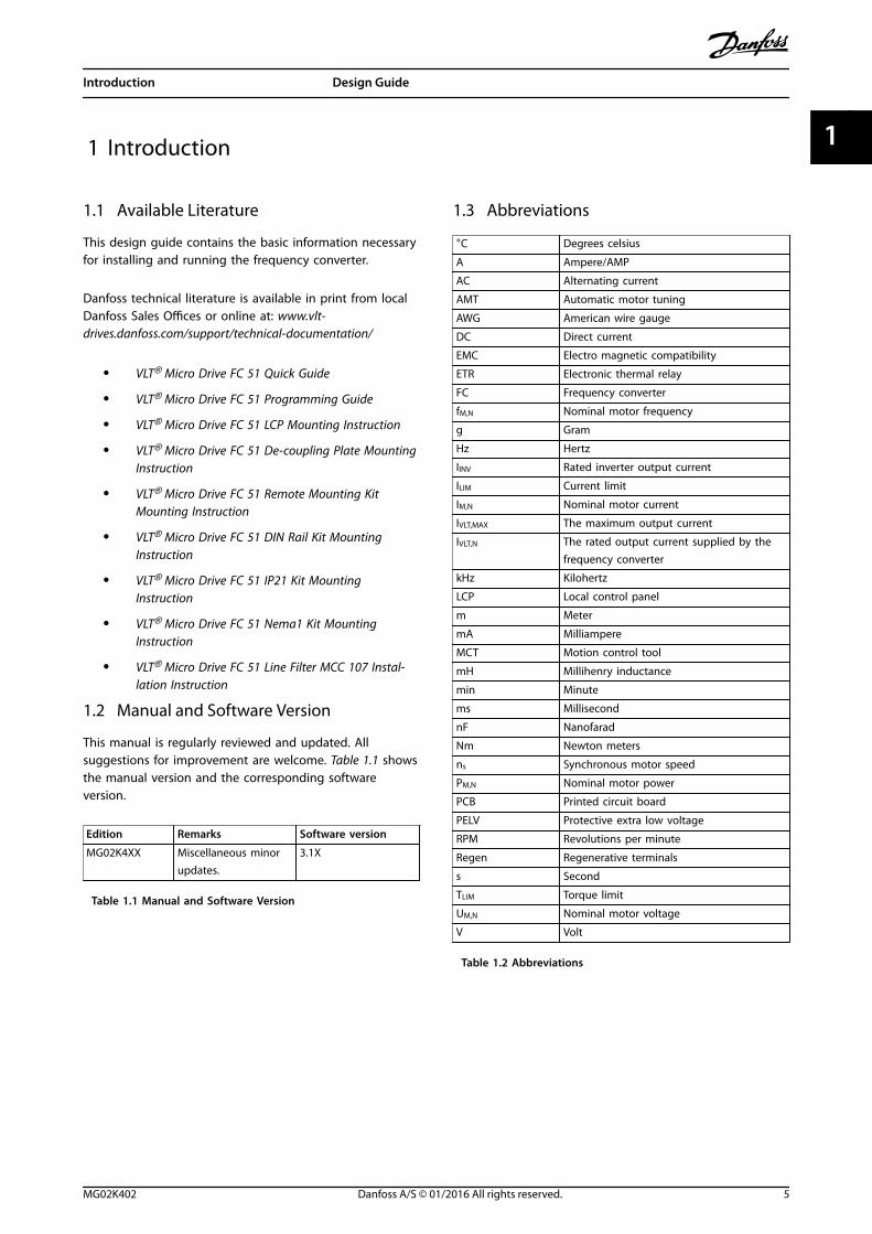
1.1 Available Literature
This design guide contains the basic information necessaryfor installing and running the frequency converter.
Danfoss technical literature is available in print from localDanfoss Sales Offices or online at: www.vlt-drives.danfoss.com/support/technical-documentation/
• VLT® Micro Drive FC 51 Quick Guide
• VLT® Micro Drive FC 51 Programming Guide
• VLT® Micro Drive FC 51 LCP Mounting Instruction
• VLT® Micro Drive FC 51 De-coupling Plate MountingInstruction
• VLT® Micro Drive FC 51 Remote Mounting KitMounting Instruction
• VLT® Micro Drive FC 51 DIN Rail Kit MountingInstruction
• VLT® Micro Drive FC 51 IP21 Kit MountingInstruction
• VLT® Micro Drive FC 51 Nema1 Kit MountingInstruction
• VLT® Micro Drive FC 51 Line Filter MCC 107 Instal-lation Instruction
1.2 Manual and Software Version
This manual is regularly reviewed and updated. Allsuggestions for improvement are welcome. Table 1.1 showsthe manual version and the corresponding softwareversion.
Edition Remarks Software version
MG02K4XX Miscellaneous minorupdates.
3.1X
Table 1.1 Manual and Software Version
1.3 Abbreviations
°C Degrees celsius
A Ampere/AMP
AC Alternating current
AMT Automatic motor tuning
AWG American wire gauge
DC Direct current
EMC Electro magnetic compatibility
ETR Electronic thermal relay
FC Frequency converter
fM,N Nominal motor frequency
g Gram
Hz Hertz
IINV Rated inverter output current
ILIM Current limit
IM,N Nominal motor current
IVLT,MAX The maximum output current
IVLT,N The rated output current supplied by thefrequency converter
kHz Kilohertz
LCP Local control panel
m Meter
mA Milliampere
MCT Motion control tool
mH Millihenry inductance
min Minute
ms Millisecond
nF Nanofarad
Nm Newton meters
ns Synchronous motor speed
PM,N Nominal motor power
PCB Printed circuit board
PELV Protective extra low voltage
RPM Revolutions per minute
Regen Regenerative terminals
s Second
TLIM Torque limit
UM,N Nominal motor voltage
V Volt
Table 1.2 Abbreviations
Introduction Design Guide
MG02K402 Danfoss A/S © 01/2016 All rights reserved. 5
1 1
1.4 Definitions
1.4.1 Frequency Converter
IVLT,MAX
The maximum output current.
IVLT N
The rated output current supplied by the frequencyconverter.
UVLT,MAX
The maximum output voltage.
1.4.2 Input
Control commandThe connected motor can be started and stopped with LCPand the digital inputs.Functions are divided into 2 groups.Functions in group 1 have higher priority than functions ingroup 2.
Group 1 Reset, coast stop, reset and coast stop, quickstop, DC brake, stop, and the [Off] key.
Group 2 Start, pulse start, reversing, start reversing, jog,and freeze output.
Table 1.3 Function Groups
1.4.3 Motor
fJOG
The motor frequency when the jog function is activated(via digital terminals).
fM
The motor frequency.
fMAX
The maximum motor frequency.
fMIN
The minimum motor frequency.
fM,N
The rated motor frequency (nameplate data).
IM
The motor current.
IM,N
The rated motor current (nameplate data).
nM,N
The nominal motor speed (nameplate data).
PM,N
The rated motor power (nameplate data).
UM
The instant motor voltage.
UM,N
The rated motor voltage (nameplate data).
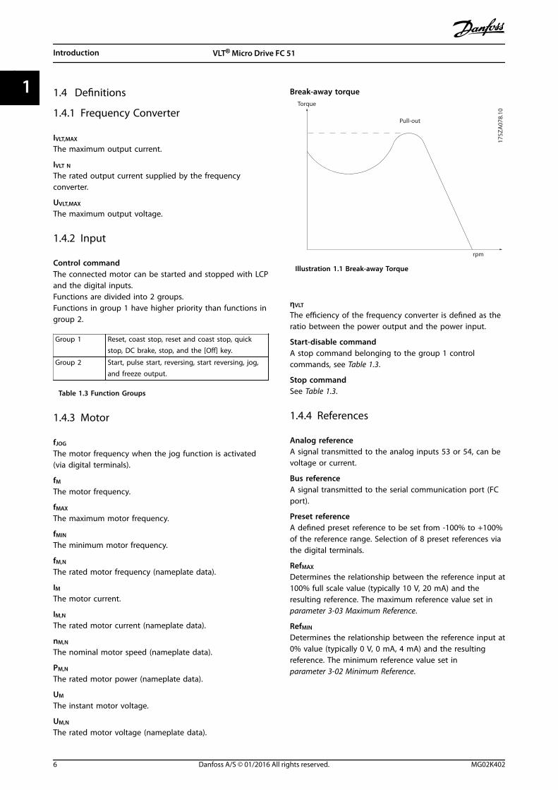
Break-away torque
175Z
A07
8.10
Pull-out
rpm
Torque
Illustration 1.1 Break-away Torque
ηVLT
The efficiency of the frequency converter is defined as theratio between the power output and the power input.
Start-disable commandA stop command belonging to the group 1 controlcommands, see Table 1.3.
Stop commandSee Table 1.3.
1.4.4 References
Analog referenceA signal transmitted to the analog inputs 53 or 54, can bevoltage or current.
Bus referenceA signal transmitted to the serial communication port (FCport).
Preset referenceA defined preset reference to be set from -100% to +100%of the reference range. Selection of 8 preset references viathe digital terminals.
RefMAX
Determines the relationship between the reference input at100% full scale value (typically 10 V, 20 mA) and theresulting reference. The maximum reference value set inparameter 3-03 Maximum Reference.
RefMIN
Determines the relationship between the reference input at0% value (typically 0 V, 0 mA, 4 mA) and the resultingreference. The minimum reference value set inparameter 3-02 Minimum Reference.
Introduction VLT® Micro Drive FC 51
6 Danfoss A/S © 01/2016 All rights reserved. MG02K402
11
1.4.5 Miscellaneous
Analog inputsThe analog inputs are used for controlling variousfunctions of the frequency converter.There are 2 types of analog inputs:
• Current input, 0–20 mA and 4–20 mA
• Voltage input, 0–10 V DC.
Analog outputsThe analog outputs can supply a signal of 0–20 mA, 4–20mA, or a digital signal.
Automatic Motor Tuning, AMTAMT algorithm determines the electrical parameters for theconnected motor at standstill.
Brake resistorThe brake resistor is a module capable of absorbing thebrake power generated in regenerative braking. Thisregenerative brake power increases the DC-link voltage,and a brake chopper ensures that the power is transmittedto the brake resistor.
CT characteristicsConstant torque characteristics used for all applicationssuch as conveyor belts, displacement pumps, and cranes.
Digital inputsThe digital inputs can be used for controlling variousfunctions of the frequency converter.
Relay outputsThe frequency converter features 2 programmable relayoutputs.
ETRElectronic thermal relay is a thermal load calculation basedon present load and time. Its purpose is to estimate themotor temperature.
InitializingIf initializing is carried out (parameter 14-22 OperationMode), the programmable parameters of the frequencyconverter return to their default settings.Initializing parameter 14-22 Operation Mode does notinitialize communication parameters.
Intermittent duty cycleAn intermittent duty rating refers to a sequence of dutycycles. Each cycle consists of an on-load and an off-loadperiod. The operation can be either periodic duty or none-periodic duty.
LCPThe local control panel makes up a complete interface forcontrol and programming of the frequency converter. Thecontrol panel is detachable and can be installed up to 3 mfrom the frequency converter, that is, in a front panel withthe installation kit option.
lsbLeast significant bit.
MCMShort for Mille Circular Mil, an American measuring unit forcable cross-section. 1 MCM ≡ 0.5067 mm2.
msbMost significant bit.
On-line/Off-line parametersChanges to on-line parameters are activated immediatelyafter the data value is changed. To activate changes to off-line parameters, press [OK].
PI controllerThe PI controller maintains the speed, pressure,temperature, and so on, by adjusting the output frequencyto match the varying load.
RCDResidual current device.
Set-upSave parameter settings in 2 set-ups. Change between the2 parameter set-ups and edit 1 set-up, while another set-up is active.
Slip compensationThe frequency converter compensates for the motor slip bygiving the frequency a supplement that follows themeasured motor load keeping the motor speed almostconstant.
Smart logic control (SLC)The SLC is a sequence of user-defined actions executedwhen the associated user-defined events are evaluated astrue by the SLC.
ThermistorA temperature-dependent resistor.
STWStatus word.
FC standard busIncludes RS485 bus with FC protocol.
TripA state entered in fault situations, for example, if thefrequency converter is subject to an overtemperature orwhen the frequency converter is protecting the motor,process, or mechanism. Restart is prevented until the causeof the fault has disappeared and the trip state is canceledby activating reset or, sometimes, by being programmed toreset automatically. Do not use trip for personal safety.
Trip lockA state entered in fault situations when the frequencyconverter is protecting itself and requiring physicalintervention, for example, if the frequency converter issubject to a short circuit on the output. A trip lock canonly be canceled by cutting off mains, removing the causeof the fault, and reconnecting the frequency converter.Restart is prevented until the trip state is canceled byactivating reset or, sometimes, by being programmed toreset automatically. Trip lock may not be used for personalsafety.
Introduction Design Guide
MG02K402 Danfoss A/S © 01/2016 All rights reserved. 7
1 1
VT characteristicsVariable torque characteristics used for pumps and fans.
VVC+
If compared with standard voltage/frequency ratio control,voltage vector control (VVC+) improves the dynamics andthe stability, both when the speed reference is changedand in relation to the load torque.
1.5 Power Factor
The power factor is the relation between I1 and IRMS.
Power factor = 3 × U × I1 × COSϕ3 × U × IRMS
The power factor for 3-phase control:
Power factor = I1 × cosϕ1IRMS
= I1IRMS
since cosϕ1 = 1
The power factor indicates to which extent the frequencyconverter imposes a load on the supply.The lower the power factor, the higher the IRMS for thesame kW performance.
IRMS = I12 + I52 + I72 + . . + In2
In addition, a high-power factor indicates that the differentharmonic currents are low.
Introduction VLT® Micro Drive FC 51
8 Danfoss A/S © 01/2016 All rights reserved. MG02K402
11
2 Safety and Conformity
2.1 Safety
The following symbols are used in this manual:
WARNINGIndicates a potentially hazardous situation that couldresult in death or serious injury.
CAUTIONIndicates a potentially hazardous situation that couldresult in minor or moderate injury. It can also be used toalert against unsafe practices.
NOTICEIndicates important information, including situations thatcan result in damage to equipment or property.
2.1.1 Safety Precautions
WARNINGHIGH VOLTAGEFrequency converters contain high voltage whenconnected to AC mains input, DC supply, or load sharing.Failure to perform installation, start-up, and maintenanceby qualified personnel can result in death or seriousinjury.
• Only qualified personnel must perform instal-lation, start-up, and maintenance.
WARNINGUNINTENDED STARTWhen the frequency converter is connected to AC mains,DC supply, or load sharing, the motor may start at anytime. Unintended start during programming, service, orrepair work can result in death, serious injury, orproperty damage. The motor can start with an externalswitch, a fieldbus command, an input reference signalfrom the LCP or LOP, via remote operation using MCT 10Set-up Software, or after a cleared fault condition.
To prevent unintended motor start:• Press [Off/Reset] on the LCP before
programming parameters.
• Disconnect the frequency converter from themains.
• Completely wire and assemble the frequencyconverter, motor, and any driven equipmentbefore connecting the frequency converter toAC mains, DC supply, or load sharing.
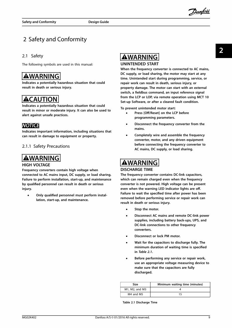
WARNINGDISCHARGE TIMEThe frequency converter contains DC-link capacitors,which can remain charged even when the frequencyconverter is not powered. High voltage can be presenteven when the warning LED indicator lights are off.Failure to wait the specified time after power has beenremoved before performing service or repair work canresult in death or serious injury.
• Stop the motor.
• Disconnect AC mains and remote DC-link powersupplies, including battery back-ups, UPS, andDC-link connections to other frequencyconverters.
• Disconnect or lock PM motor.
• Wait for the capacitors to discharge fully. Theminimum duration of waiting time is specifiedin Table 2.1.
• Before performing any service or repair work,use an appropriate voltage measuring device tomake sure that the capacitors are fullydischarged.
Size Minimum waiting time (minutes)
M1, M2, and M3 4
M4 and M5 15
Table 2.1 Discharge Time
Safety and Conformity Design Guide
MG02K402 Danfoss A/S © 01/2016 All rights reserved. 9
2 2
WARNINGLEAKAGE CURRENT HAZARDLeakage currents exceed 3.5 mA. Failure to ground thefrequency converter properly can result in death orserious injury.
• Ensure the correct grounding of the equipmentby a certified electrical installer.
WARNINGEQUIPMENT HAZARDContact with rotating shafts and electrical equipmentcan result in death or serious injury.
• Ensure that only trained and qualified personnelperform installation, start-up, and maintenance.
• Ensure that electrical work conforms to nationaland local electrical codes.
• Follow the procedures in this guide.
WARNINGUNINTENDED MOTOR ROTATIONWINDMILLINGUnintended rotation of permanent magnet motorscreates voltage and can charge the unit, resulting indeath, serious injury, or equipment damage.
• Ensure that permanent magnet motors areblocked to prevent unintended rotation.
CAUTIONINTERNAL FAILURE HAZARDAn internal failure in the frequency converter can resultin serious injury when the frequency converter is notproperly closed.
• Ensure that all safety covers are in place andsecurely fastened before applying power.
2.2 Disposal InstructionEquipment containing electricalcomponents cannot be disposed oftogether with domestic waste.It must be separately collected withelectrical and electronic waste accordingto local and currently valid legislation.
2.3 Approvals
The frequency converter complies with UL 508C thermalmemory retention requirements. For more informationrefer to chapter 3.5.1 Motor Thermal Protection.
2.4 CE Labeling
2.4.1 CE Conformity and Labeling
What is CE conformity and labeling?The purpose of CE labelling is to avoid technical tradeobstacles within EFTA and the EU. The EU has introducedthe CE label as a simple way of showing whether aproduct complies with the relevant EU directives. The CElabel says nothing about the specifications or quality ofthe product. Frequency converters are regulated by 3 EUdirectives:
The Machinery Directive (98/37/EEC)All machines with critical moving parts are covered by themachinery directive of January 1, 1995. Since a frequencyconverter is largely electrical, it does not fall under themachinery directive. However, if a frequency converter issupplied for use in a machine, Danfoss providesinformation on safety aspects relating to the frequencyconverter. Danfoss does this with a manufacturer'sdeclaration.
The Low Voltage Directive (73/23/EEC)Frequency converters must be CE labeled in accordancewith the Low Voltage Directive of January 1, 1997. Thedirective applies to all electrical equipment and appliancesused in the 50–1000 V AC and the 75–1500 V DC voltageranges. Danfoss CE-labels in accordance with the directiveand issues a declaration of conformity on request.
The EMC Directive (2004/108/EC)EMC is short for electromagnetic compatibility. Thepresence of electromagnetic compatibility means that themutual interference between different components/appliances does not affect the way the appliances work.The EMC directive came into effect January 1, 1996.Danfoss CE-labels in accordance with the directive andissues a declaration of conformity after request. To carryout EMC-correct installation, see the instructions in thisdesign guide. In addition, Danfoss specifies whichstandards our products comply with. Danfoss offers thefilters presented in the specifications and provide othertypes of assistance to ensure the optimum EMC result.
The frequency converter is most often used by profes-sionals of the trade as a complex component forming partof a larger appliance, system, or installation. Note that theresponsibility for the final EMC properties of the appliance,system or installation rests with the installer.
Safety and Conformity VLT® Micro Drive FC 51
10 Danfoss A/S © 01/2016 All rights reserved. MG02K402
22
2.4.2 What is Covered
The EU Guidelines on the Application of Council Directive89/336/EEC outline 3 typical situations of using a frequencyconverter. See chapter 2.4.3 Danfoss Frequency Converterand CE Labelling for EMC coverage and CE labelling.
• The frequency converter is sold directly to theend-consumer. The frequency converter is forexample sold to a DIY market. The end-consumeris a layman. The end-consumer installs thefrequency converter himself for use with a hobbymachine, a kitchen appliance, and so on. For suchapplications, the frequency converter must be CElabeled in accordance with the EMC directive.
• The frequency converter is sold for installation ina plant. The plant is built up by professionals ofthe trade. It could be a production plant or aheating/ventilation plant designed and installedby professionals of the trade. Neither thefrequency converter nor the finished plant has tobe CE labeled under the EMC directive. However,the unit must comply with the basic EMCrequirements of the directive. This is ensured byusing components, appliances, and systems thatare CE labeled under the EMC directive.
• The frequency converter is sold as part of acomplete system. The system is being marketedas complete and could for example, be an air-conditioning system. The complete system mustbe CE labeled in accordance with the EMCdirective. The manufacturer can ensure CElabelling under the EMC directive either by usingCE labeled components or by testing the EMC ofthe system. It is not necessary to test the entiresystem if only CE labeled components areselected.
2.4.3 Danfoss Frequency Converter and CELabelling
CE labelling is a positive feature when used for its originalpurpose, that is, to facilitate trade within the EU and EFTA.
However, CE labelling may cover many different specifi-cations. Check what a given CE label specifically covers.
The covered specifications can be different and a CE labelmay therefore give the installer a false feeling of securitywhen using a frequency converter as a component in asystem or an appliance.
Danfoss CE labels the frequency converters in accordancewith the Low Voltage Directive. This means that if thefrequency converter is installed correctly, Danfoss
guarantees compliance with the Low Voltage Directive.Danfoss issues a declaration of conformity that confirmsour CE labelling in accordance with the Low VoltageDirective.
The CE label also applies to the EMC directive if theinstructions for EMC-correct installation and filtering arefollowed. On this basis, a declaration of conformity inaccordance with the EMC directive is issued.
The design guide offers detailed instructions for installationto ensure EMC-correct installation. Furthermore, Danfossspecifies which our different products comply with.
Danfoss provides other types of assistance that can help toobtain the best EMC result.
2.4.4 Compliance with EMC Directive2004/108/EC
As mentioned, the frequency converter is mostly used byprofessionals of the trade as a complex componentforming part of a larger appliance, system, or installation.Note that the responsibility for the final EMC properties ofthe appliance, system, or installation rests with the installer.As an aid to the installer, Danfoss has prepared EMC instal-lation guidelines for the power drive system. If the EMC-correct instructions for installation are followed, thestandards and test levels stated for power drive systemsare complied with.
2.5 Air Humidity
The frequency converter has been designed to meet theIEC/EN 60068-2-3 standard, EN 50178 9.4.2.2 at 50 °C(122 °F).
2.6 Aggressive Environments
A frequency converter contains many mechanical andelectronic components. All are to some extent vulnerableto environmental effects.
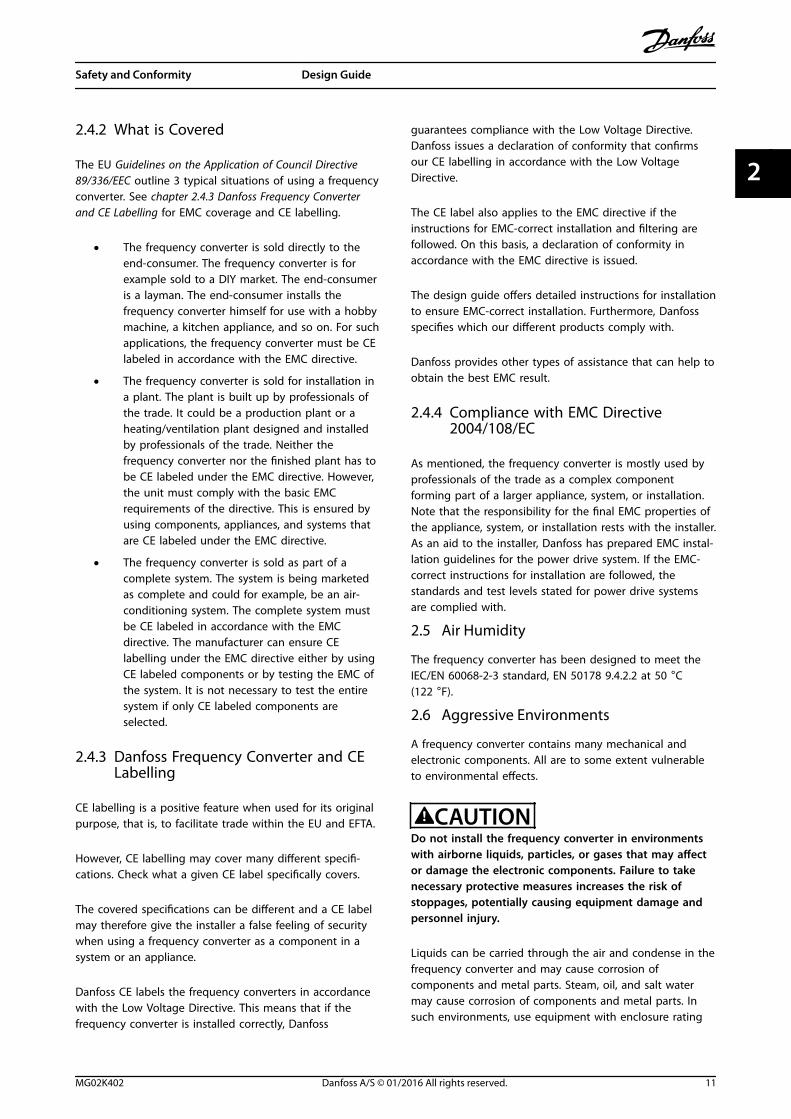
CAUTIONDo not install the frequency converter in environmentswith airborne liquids, particles, or gases that may affector damage the electronic components. Failure to takenecessary protective measures increases the risk ofstoppages, potentially causing equipment damage andpersonnel injury.
Liquids can be carried through the air and condense in thefrequency converter and may cause corrosion ofcomponents and metal parts. Steam, oil, and salt watermay cause corrosion of components and metal parts. Insuch environments, use equipment with enclosure rating
Safety and Conformity Design Guide
MG02K402 Danfoss A/S © 01/2016 All rights reserved. 11
2 2
IP54. As an extra protection, coated printed circuit boardscan be ordered as an option (standard on some powersizes).
Airborne particles such as dust may cause mechanical,electrical, or thermal failure in the frequency converter. Atypical indicator of excessive levels of airborne particles isdust particles around the frequency converter fan. In dustyenvironments, use equipment with enclosure rating IP54 ora cabinet for IP20/TYPE 1 equipment.
In environments with high temperatures and humidity,corrosive gases such as sulphur, nitrogen, and chlorinecompounds cause chemical processes on the frequencyconverter components.
Such chemical reactions rapidly affect and damage theelectronic components. In such environments, mount theequipment in a cabinet with fresh air ventilation, keepingaggressive gases away from the frequency converter.An extra protection in such areas is a coating of theprinted circuit boards, which can be ordered as an option.
Before installing the frequency converter, check theambient air for liquids, particles, and gases. This is done byobserving existing installations in this environment. Typicalindicators of harmful airborne liquids are water or oil onmetal parts, or corrosion of metal parts.
Excessive dust particle levels are often found on instal-lation cabinets and existing electrical installations. Oneindicator of aggressive airborne gases is blackening ofcopper rails and cable ends on existing installations.
2.7 Vibration and Shock
The frequency converter has been tested according to theprocedure based on the shown standards, Table 2.2.
The frequency converter complies with requirements thatexist for units mounted on the walls and floors ofproduction premises, and in panels bolted to walls orfloors.
IEC/EN 60068-2-6 Vibration (sinusoidal) - 1970
IEC/EN 60068-2-64 Vibration, broad-band random
Table 2.2 Standards
2.8 Advantages
2.8.1 Why use a Frequency Converter forControlling Fans and Pumps?
A frequency converter takes advantage of the fact thatcentrifugal fans and pumps follow the laws of propor-tionality for such fans and pumps. For further information,see chapter 2.8.3 Example of Energy Savings.
2.8.2 The Clear Advantage - Energy Savings
The clear advantage of using a frequency converter forcontrolling the speed of fans or pumps lies in theelectricity savings.When comparing with alternative control systems andtechnologies, a frequency converter is the optimum energycontrol system for controlling fan and pump systems.
130B
A78
0.11
SYSTEM CURVE
FAN CURVE
PRES
SURE
%
A
B
C
0
20
40
60
80
100
120
20 40 60 80 100 120 140 160 180VOLUME %
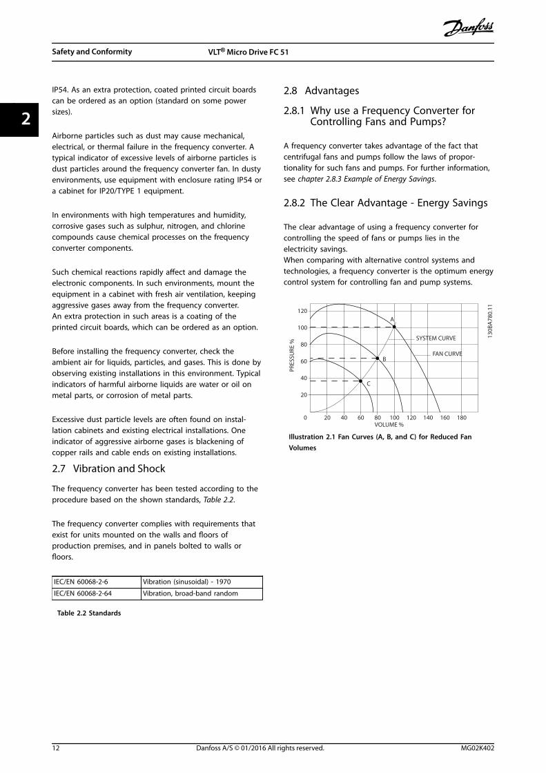
Illustration 2.1 Fan Curves (A, B, and C) for Reduced FanVolumes
Safety and Conformity VLT® Micro Drive FC 51
12 Danfoss A/S © 01/2016 All rights reserved. MG02K402
22
120
100
80
60
40
20
0 20 40 60 80 100 120 140 160 180
120
100
80
60
40
20
0 20 40 60 80 100 120 140 160 180
Volume %
Volume %
INPU
T PO
WER
%PR
ESSU
RE %
SYSTEM CURVE
FAN CURVE
A
B
C
130B
A78
1.11
ENERGYCONSUMED
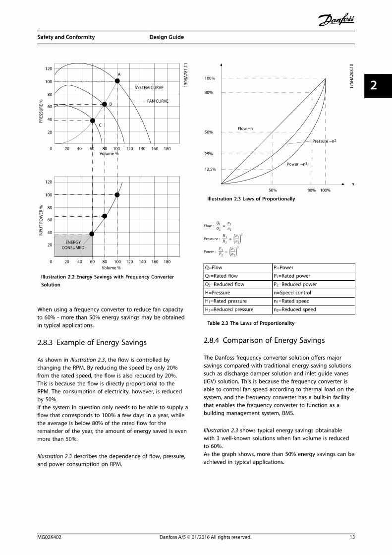
Illustration 2.2 Energy Savings with Frequency ConverterSolution
When using a frequency converter to reduce fan capacityto 60% - more than 50% energy savings may be obtainedin typical applications.
2.8.3 Example of Energy Savings
As shown in Illustration 2.3, the flow is controlled bychanging the RPM. By reducing the speed by only 20%from the rated speed, the flow is also reduced by 20%.This is because the flow is directly proportional to theRPM. The consumption of electricity, however, is reducedby 50%.If the system in question only needs to be able to supply aflow that corresponds to 100% a few days in a year, whilethe average is below 80% of the rated flow for theremainder of the year, the amount of energy saved is evenmore than 50%.
Illustration 2.3 describes the dependence of flow, pressure,and power consumption on RPM.
n
100%
50%
25%
12,5%
50% 100%
80%
80%
175H
A20
8.10
Power ~n 3
Pressure ~n 2
Flow ~n
Illustration 2.3 Laws of Proportionally
Flow : Q1Q2 = n1n2
Pressure : H1H2 = n1n2
2
Power : P1P2 = n1n2
3
Q=Flow P=Power
Q1=Rated flow P1=Rated power
Q2=Reduced flow P2=Reduced power
H=Pressure n=Speed control
H1=Rated pressure n1=Rated speed
H2=Reduced pressure n2=Reduced speed
Table 2.3 The Laws of Proportionality
2.8.4 Comparison of Energy Savings
The Danfoss frequency converter solution offers majorsavings compared with traditional energy saving solutionssuch as discharge damper solution and inlet guide vanes(IGV) solution. This is because the frequency converter isable to control fan speed according to thermal load on thesystem, and the frequency converter has a built-in facilitythat enables the frequency converter to function as abuilding management system, BMS.
Illustration 2.3 shows typical energy savings obtainablewith 3 well-known solutions when fan volume is reducedto 60%.As the graph shows, more than 50% energy savings can beachieved in typical applications.
Safety and Conformity Design Guide
MG02K402 Danfoss A/S © 01/2016 All rights reserved. 13
2 2
130B
A78
2.10
Dischargedamper
Less energy savings
IGV
Costlier installation
Maximum energy savings
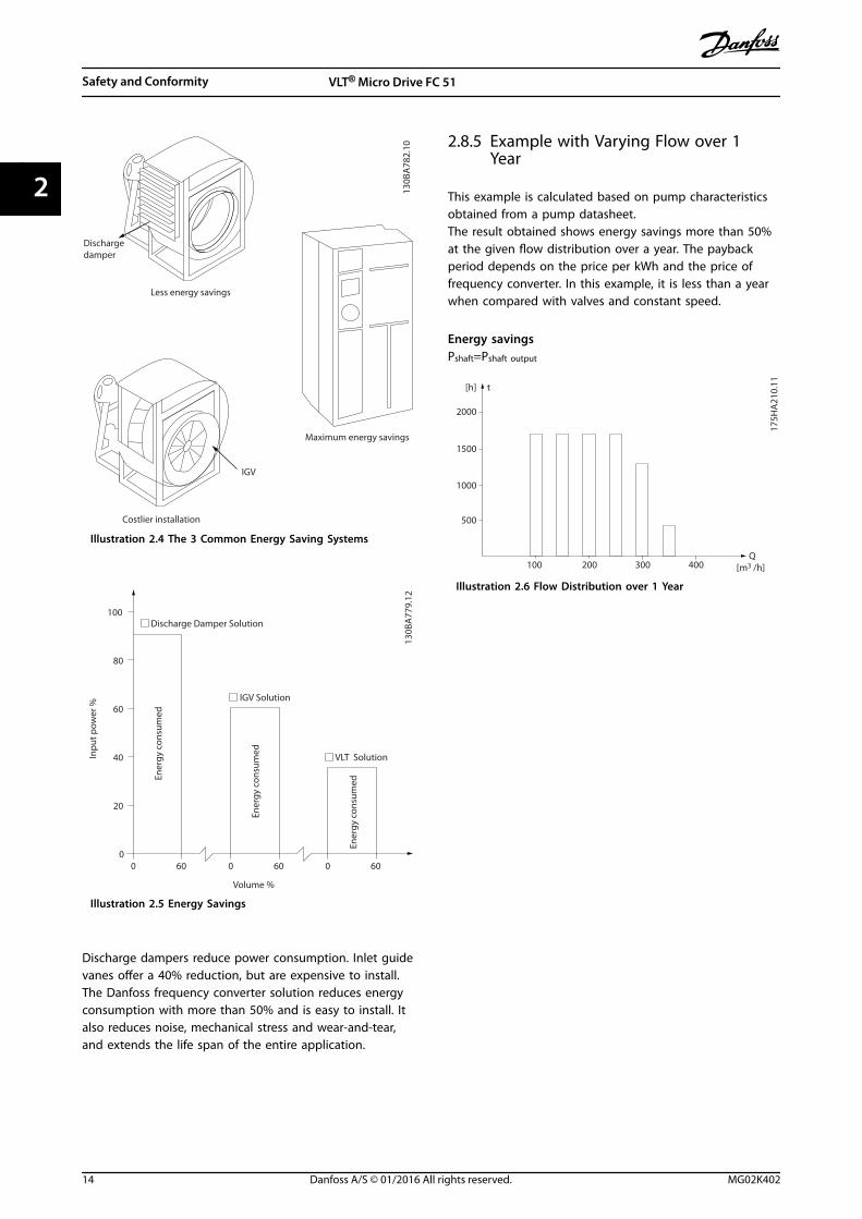
Illustration 2.4 The 3 Common Energy Saving Systems
130B
A77
9.12
0 60 0 60 0 600
20
40
60
80
100Discharge Damper Solution
IGV Solution
VLT Solution
Ener
gy c
onsu
med
Ener
gy c
onsu
med
Ener
gy c
onsu
med
Inpu
t pow
er %
Volume %
Illustration 2.5 Energy Savings
Discharge dampers reduce power consumption. Inlet guidevanes offer a 40% reduction, but are expensive to install.The Danfoss frequency converter solution reduces energyconsumption with more than 50% and is easy to install. Italso reduces noise, mechanical stress and wear-and-tear,and extends the life span of the entire application.
2.8.5 Example with Varying Flow over 1Year
This example is calculated based on pump characteristicsobtained from a pump datasheet.The result obtained shows energy savings more than 50%at the given flow distribution over a year. The paybackperiod depends on the price per kWh and the price offrequency converter. In this example, it is less than a yearwhen compared with valves and constant speed.
Energy savingsPshaft=Pshaft output
500
[h] t
1000
1500
2000
200100 300 [m3 /h]400Q
175H
A21
0.11
Illustration 2.6 Flow Distribution over 1 Year
Safety and Conformity VLT® Micro Drive FC 51
14 Danfoss A/S © 01/2016 All rights reserved. MG02K402
22
175H
A20
9.11
60
50
40
30
20
10
Hs
0 100 200 300 400
(mwg)
B
C
A
750rpm
1050rpm
1350rpm
1650rpm
0
10
20
30
(kW)
40
50
60
200100 300 (m3 /h)
(m3 /h)
400
750rpm
1050rpm
1350rpm
1650rpm
Pshaft
C1
B1
A1
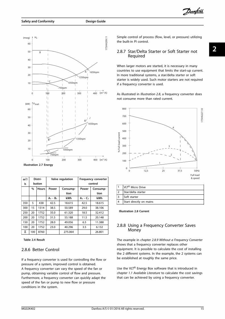
Illustration 2.7 Energy
m3/h
Distri-bution
Valve regulation Frequency convertercontrol
% Hours Power Consump-tion
Power Consump-tion
A1 - B1 kWh A1 - C1 kWh
350 5 438 42.5 18.615 42.5 18.615
300 15 1314 38.5 50.589 29.0 38.106
250 20 1752 35.0 61.320 18.5 32.412
200 20 1752 31.5 55.188 11.5 20.148
150 20 1752 28.0 49.056 6.5 11.388
100 20 1752 23.0 40.296 3.5 6.132
Σ 100 8760 275.064 26.801
Table 2.4 Result
2.8.6 Better Control
If a frequency converter is used for controlling the flow orpressure of a system, improved control is obtained.A frequency converter can vary the speed of the fan orpump, obtaining variable control of flow and pressure.Furthermore, a frequency converter can quickly adapt thespeed of the fan or pump to new flow or pressureconditions in the system.
Simple control of process (flow, level, or pressure) utilizingthe built-in PI control.
2.8.7 Star/Delta Starter or Soft Starter notRequired
When larger motors are started, it is necessary in manycountries to use equipment that limits the start-up current.In more traditional systems, a star/delta starter or softstarter is widely used. Such motor starters are not requiredif a frequency converter is used.
As illustrated in Illustration 2.8, a frequency converter doesnot consume more than rated current.
Full load
% F
ull-l
oad
curr
ent
& speed
500
100
00 12,5 25 37,5 50Hz
200
300
400
600
700
800
4
3
2
1
175H
A22
7.10
1 VLT® Micro Drive
2 Star/delta starter
3 Soft starter
4 Start directly on mains
Illustration 2.8 Current
2.8.8 Using a Frequency Converter SavesMoney
The example in chapter 2.8.9 Without a Frequency Convertershows that a frequency converter replaces otherequipment. It is possible to calculate the cost of installingthe 2 different systems. In the example, the 2 systems canbe established at roughly the same price.
Use the VLT® Energy Box software that is introduced inchapter 1.1 Available Literature to calculate the cost savingsthat can be achieved by using a frequency converter.
Safety and Conformity Design Guide
MG02K402 Danfoss A/S © 01/2016 All rights reserved. 15
2 2
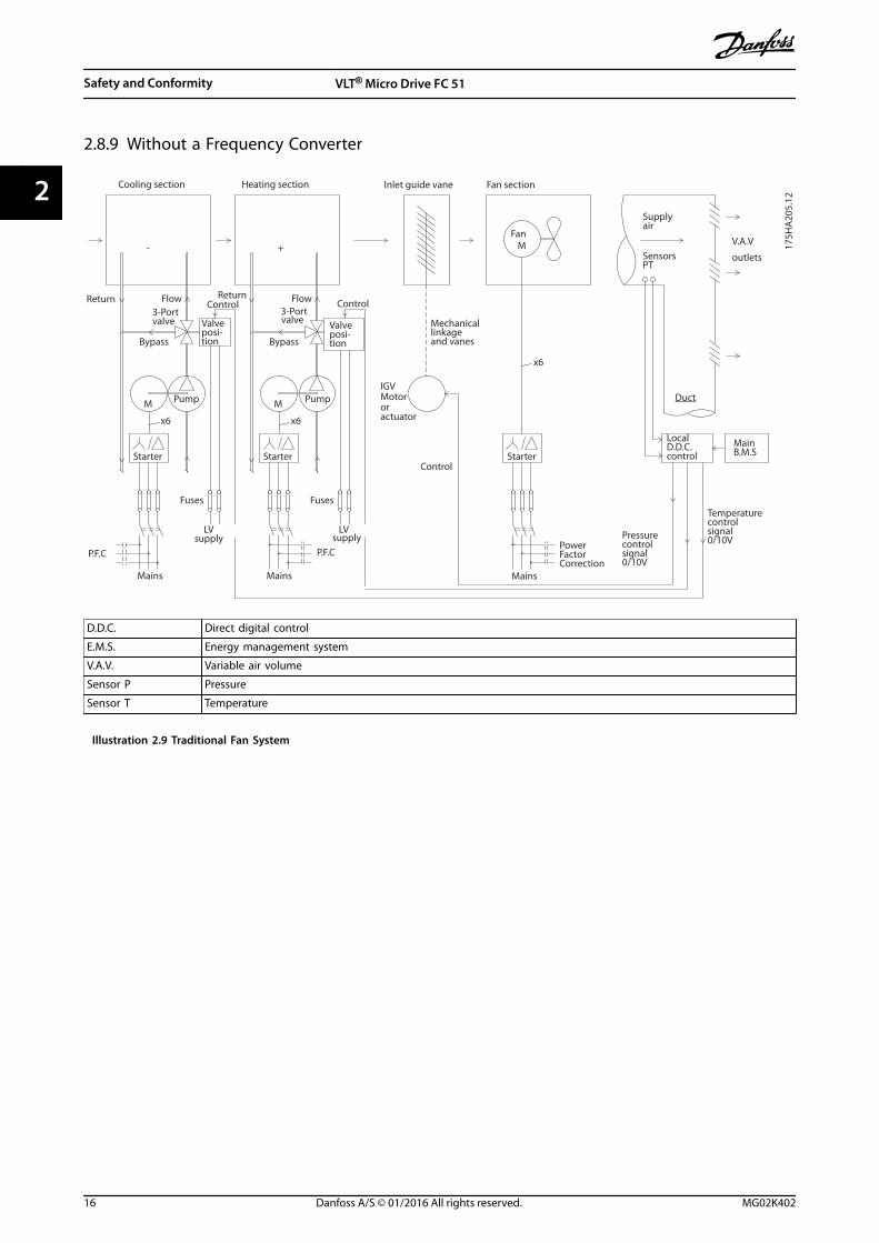
2.8.9 Without a Frequency Converter
M
- +
M
M
x6 x6
x6
175H
A20
5.12
Valveposi-tion
Starter
Fuses
LVsupply
P.F.C
Flow3-Portvalve
Bypass
Return Control
Supplyair
V.A.V
outlets
Duct
P.F.C
Mains
Fuses
Starter
Bypass
supplyLV
Return
valve3-Port
Flow Control
Valveposi-tion
Starter
PowerFactorCorrection
Mains
IGV
Mechanicallinkageand vanes
Fan
Motororactuator
MainB.M.S
LocalD.D.C.control
SensorsPT
Pressurecontrolsignal0/10V
Temperaturecontrolsignal0/10V
Control
Mains
Cooling section Heating section Fan sectionInlet guide vane
Pump Pump
D.D.C. Direct digital control
E.M.S. Energy management system
V.A.V. Variable air volume
Sensor P Pressure
Sensor T Temperature
Illustration 2.9 Traditional Fan System
Safety and Conformity VLT® Micro Drive FC 51
16 Danfoss A/S © 01/2016 All rights reserved. MG02K402
22
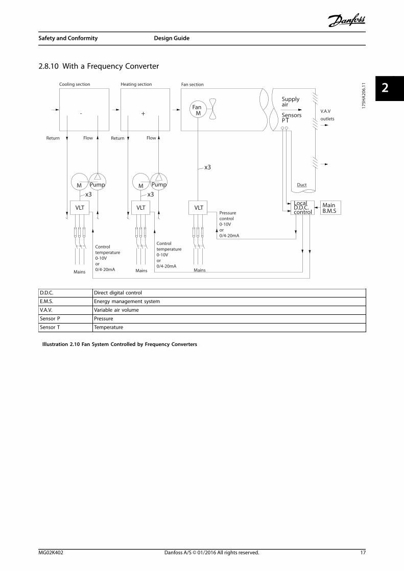
2.8.10 With a Frequency Converter
175H
A20
6.11
Pump
FlowReturn
Supplyair
V.A.V
outlets
Duct
Mains
Pump
Return Flow
Mains
Fan
MainB.M.S
LocalD.D.C.control
Sensors
Mains
Cooling section Heating section Fan section
Pressurecontrol0-10Vor0/4-20mA
Controltemperature0-10Vor0/4-20mA
Controltemperature0-10Vor0/4-20mA
VLT
M
- +
VLT
M
MPT
VLT
x3 x3
x3
D.D.C. Direct digital control
E.M.S. Energy management system
V.A.V. Variable air volume
Sensor P Pressure
Sensor T Temperature
Illustration 2.10 Fan System Controlled by Frequency Converters
Safety and Conformity Design Guide
MG02K402 Danfoss A/S © 01/2016 All rights reserved. 17
2 2
3 Product Overview
3.1 Control Structures
Select the configuration mode in parameter 1-00 Configuration Mode.
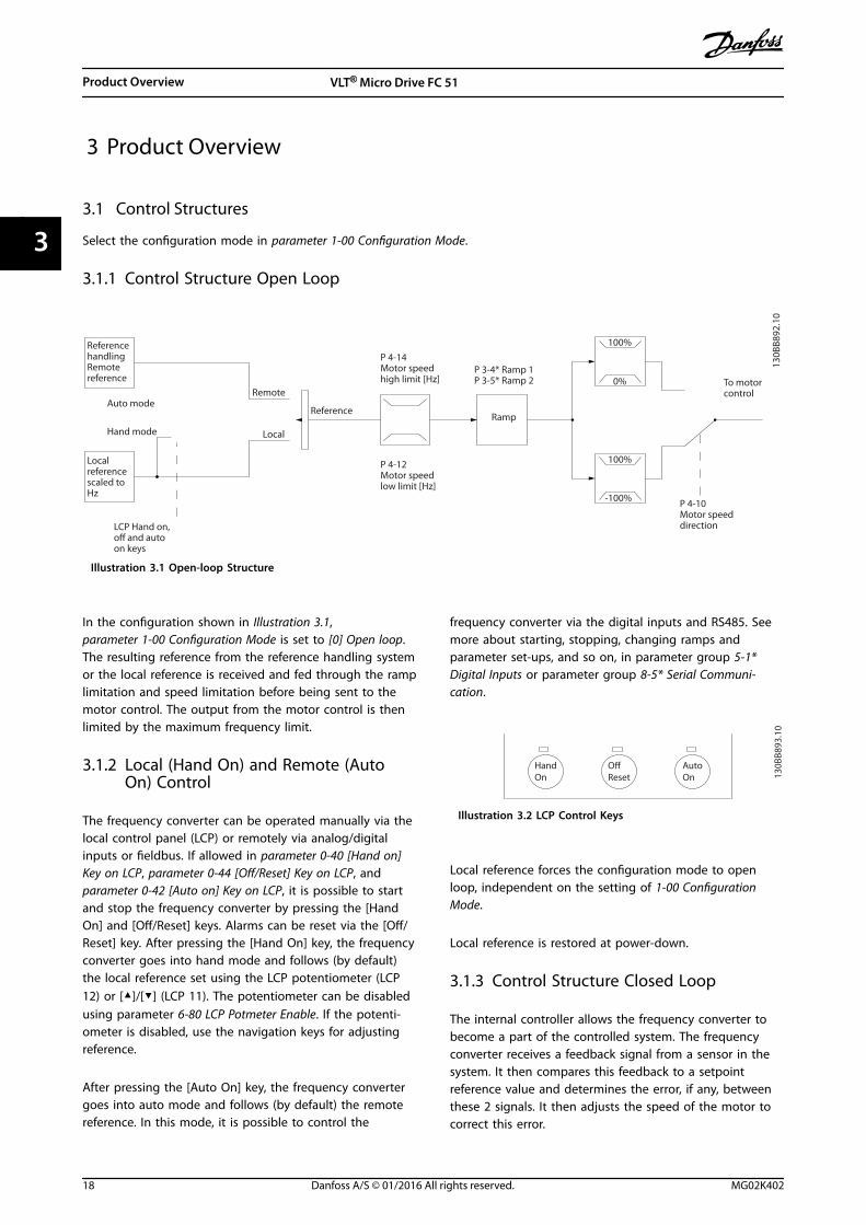
3.1.1 Control Structure Open Loop
130B
B892
.10
100%
0%
-100%
100%Localreferencescaled toHz
Auto mode
Hand mode
LCP Hand on,off and autoon keys
Local
Remote
ReferenceRamp
P 4-10Motor speeddirection
To motorcontrol
ReferencehandlingRemotereference
P 4-14Motor speedhigh limit [Hz]
P 4-12Motor speedlow limit [Hz]
P 3-4* Ramp 1P 3-5* Ramp 2
Illustration 3.1 Open-loop Structure
In the configuration shown in Illustration 3.1,parameter 1-00 Configuration Mode is set to [0] Open loop.The resulting reference from the reference handling systemor the local reference is received and fed through the ramplimitation and speed limitation before being sent to themotor control. The output from the motor control is thenlimited by the maximum frequency limit.
3.1.2 Local (Hand On) and Remote (AutoOn) Control
The frequency converter can be operated manually via thelocal control panel (LCP) or remotely via analog/digitalinputs or fieldbus. If allowed in parameter 0-40 [Hand on]Key on LCP, parameter 0-44 [Off/Reset] Key on LCP, andparameter 0-42 [Auto on] Key on LCP, it is possible to startand stop the frequency converter by pressing the [HandOn] and [Off/Reset] keys. Alarms can be reset via the [Off/Reset] key. After pressing the [Hand On] key, the frequencyconverter goes into hand mode and follows (by default)the local reference set using the LCP potentiometer (LCP12) or [▲]/[▼] (LCP 11). The potentiometer can be disabledusing parameter 6-80 LCP Potmeter Enable. If the potenti-ometer is disabled, use the navigation keys for adjustingreference.
After pressing the [Auto On] key, the frequency convertergoes into auto mode and follows (by default) the remotereference. In this mode, it is possible to control the
frequency converter via the digital inputs and RS485. Seemore about starting, stopping, changing ramps andparameter set-ups, and so on, in parameter group 5-1*Digital Inputs or parameter group 8-5* Serial Communi-cation.
HandOn
OffReset
AutoOn 13
0BB8
93.1
0
Illustration 3.2 LCP Control Keys
Local reference forces the configuration mode to openloop, independent on the setting of 1-00 ConfigurationMode.
Local reference is restored at power-down.
3.1.3 Control Structure Closed Loop
The internal controller allows the frequency converter tobecome a part of the controlled system. The frequencyconverter receives a feedback signal from a sensor in thesystem. It then compares this feedback to a setpointreference value and determines the error, if any, betweenthese 2 signals. It then adjusts the speed of the motor tocorrect this error.
Product Overview VLT® Micro Drive FC 51
18 Danfoss A/S © 01/2016 All rights reserved. MG02K402
33
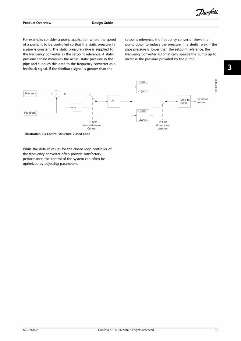
For example, consider a pump application where the speedof a pump is to be controlled so that the static pressure ina pipe is constant. The static pressure value is supplied tothe frequency converter as the setpoint reference. A staticpressure sensor measures the actual static pressure in thepipe and supplies this data to the frequency converter as afeedback signal. If the feedback signal is greater than the
setpoint reference, the frequency converter slows thepump down to reduce the pressure. In a similar way, if thepipe pressure is lower than the setpoint reference, thefrequency converter automatically speeds the pump up toincrease the pressure provided by the pump.
7-30 PI Normal/Inverse
Control
PI
Reference
Feedback
Scale tospeed
P 4-10Motor speed
direction
To motorcontrol
130B
B894
.11
S
100%
0%
-100%
100%*[-1]
_
+
Illustration 3.3 Control Structure Closed Loop
While the default values for the closed-loop controller ofthe frequency converter often provide satisfactoryperformance, the control of the system can often beoptimized by adjusting parameters.
Product Overview Design Guide
MG02K402 Danfoss A/S © 01/2016 All rights reserved. 19
3 3
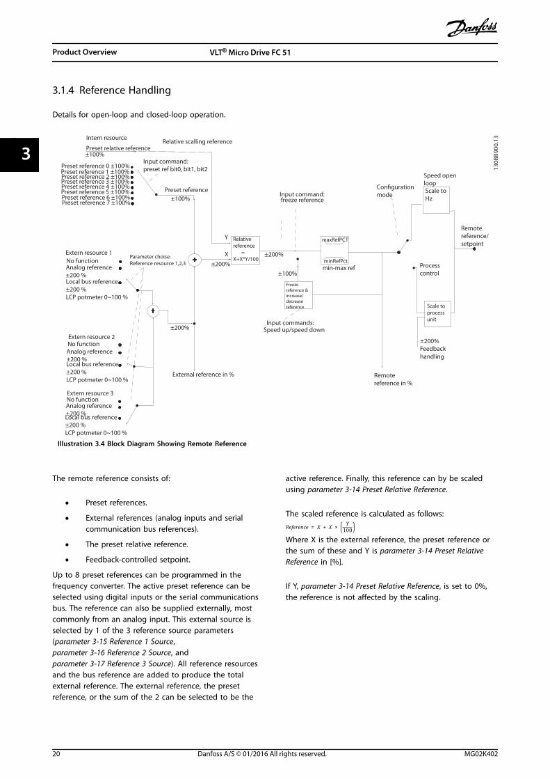
3.1.4 Reference Handling
Details for open-loop and closed-loop operation.
Speed open loopCon�guration
modeInput command:freeze reference
Processcontrol
Scale toHz
Scale toprocessunit
Remotereference/setpoint
±200%Feedbackhandling
Remote reference in %
maxRefPCT
minRefPctmin-max ref
Freezereference &increase/decreasereference
±100%
Input commands:Speed up/speed down
±200%
Relativereference =X+X*Y/100
±200%
External reference in %
±200%
Parameter choise:Reference resource 1,2,3
±100%Preset reference
Input command:preset ref bit0, bit1, bit2
+
+
Relative scalling referenceIntern resource
Preset relative reference±100%
Preset reference 0 ±100%Preset reference 1 ±100%Preset reference 2 ±100%Preset reference 3 ±100%Preset reference 4 ±100%Preset reference 5 ±100%Preset reference 6 ±100%Preset reference 7 ±100%
Extern resource 1No functionAnalog reference ±200 %Local bus reference ±200 %LCP potmeter 0~100 %
Extern resource 2No functionAnalog reference ±200 %Local bus reference ±200 %LCP potmeter 0~100 %
Extern resource 3No function Analog reference ±200 %Local bus reference ±200 %LCP potmeter 0~100 %
Y
X
130B
B900
.13
Illustration 3.4 Block Diagram Showing Remote Reference
The remote reference consists of:
• Preset references.
• External references (analog inputs and serialcommunication bus references).
• The preset relative reference.
• Feedback-controlled setpoint.
Up to 8 preset references can be programmed in thefrequency converter. The active preset reference can beselected using digital inputs or the serial communicationsbus. The reference can also be supplied externally, mostcommonly from an analog input. This external source isselected by 1 of the 3 reference source parameters(parameter 3-15 Reference 1 Source,parameter 3-16 Reference 2 Source, andparameter 3-17 Reference 3 Source). All reference resourcesand the bus reference are added to produce the totalexternal reference. The external reference, the presetreference, or the sum of the 2 can be selected to be the
active reference. Finally, this reference can by be scaledusing parameter 3-14 Preset Relative Reference.
The scaled reference is calculated as follows:Reference = X + X × Y
100Where X is the external reference, the preset reference orthe sum of these and Y is parameter 3-14 Preset RelativeReference in [%].
If Y, parameter 3-14 Preset Relative Reference, is set to 0%,the reference is not affected by the scaling.
Product Overview VLT® Micro Drive FC 51
20 Danfoss A/S © 01/2016 All rights reserved. MG02K402
33
3.2 General Aspects of EMC
3.2.1 General Aspects of EMC Emissions
Frequency converters (and other electrical devices)generate electronic or magnetic fields that may interferewith their environment. The electromagnetic compatibility(EMC) of these effects depends on the power and theharmonic characteristics of the devices.
Uncontrolled interaction between electrical devices in asystem can degrade compatibility and impair reliableoperation. Interference may take the form of mainsharmonics distortion, electrostatic discharges, rapid voltagefluctuations, or high frequency interference. Electricaldevices generate interference along with being affected byinterference from other generated sources.
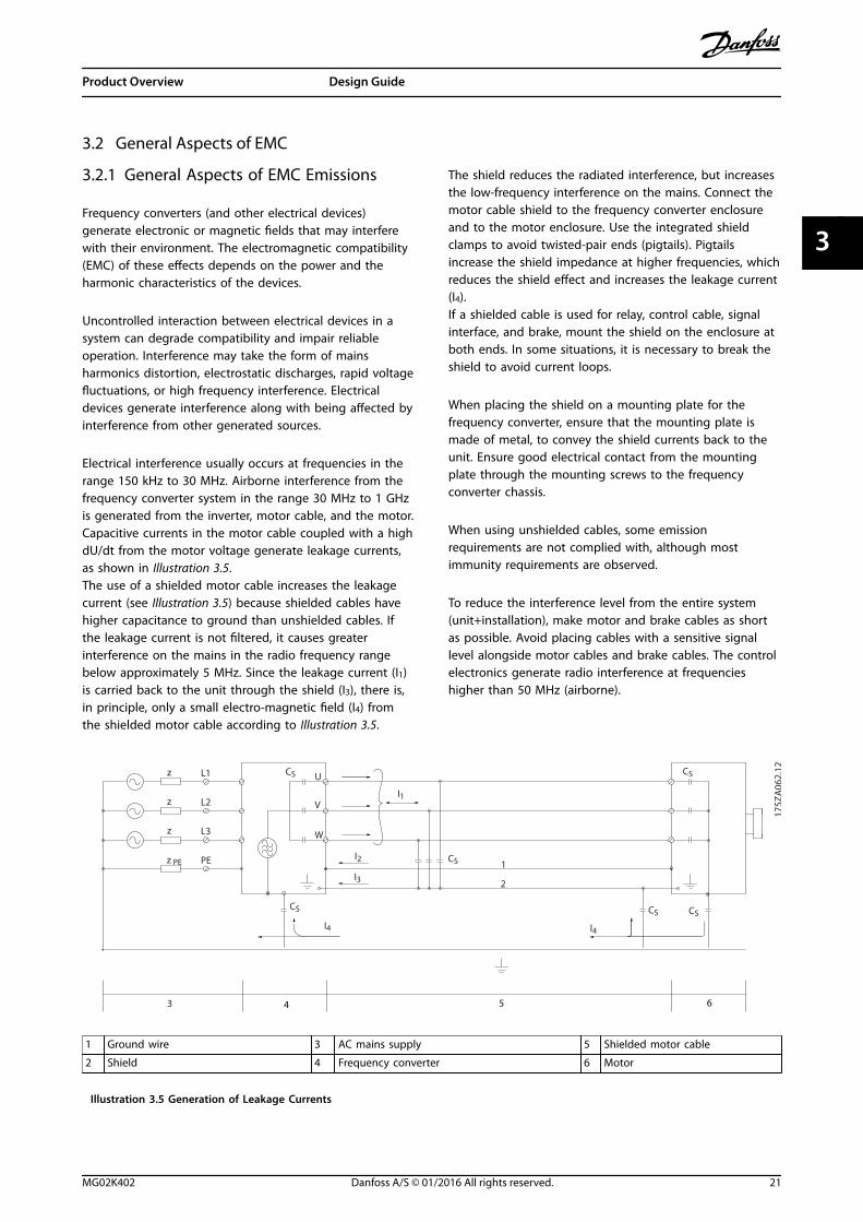
Electrical interference usually occurs at frequencies in therange 150 kHz to 30 MHz. Airborne interference from thefrequency converter system in the range 30 MHz to 1 GHzis generated from the inverter, motor cable, and the motor.Capacitive currents in the motor cable coupled with a highdU/dt from the motor voltage generate leakage currents,as shown in Illustration 3.5.The use of a shielded motor cable increases the leakagecurrent (see Illustration 3.5) because shielded cables havehigher capacitance to ground than unshielded cables. Ifthe leakage current is not filtered, it causes greaterinterference on the mains in the radio frequency rangebelow approximately 5 MHz. Since the leakage current (I1)is carried back to the unit through the shield (I3), there is,in principle, only a small electro-magnetic field (I4) fromthe shielded motor cable according to Illustration 3.5.
The shield reduces the radiated interference, but increasesthe low-frequency interference on the mains. Connect themotor cable shield to the frequency converter enclosureand to the motor enclosure. Use the integrated shieldclamps to avoid twisted-pair ends (pigtails). Pigtailsincrease the shield impedance at higher frequencies, whichreduces the shield effect and increases the leakage current(I4).If a shielded cable is used for relay, control cable, signalinterface, and brake, mount the shield on the enclosure atboth ends. In some situations, it is necessary to break theshield to avoid current loops.
When placing the shield on a mounting plate for thefrequency converter, ensure that the mounting plate ismade of metal, to convey the shield currents back to theunit. Ensure good electrical contact from the mountingplate through the mounting screws to the frequencyconverter chassis.
When using unshielded cables, some emissionrequirements are not complied with, although mostimmunity requirements are observed.
To reduce the interference level from the entire system(unit+installation), make motor and brake cables as shortas possible. Avoid placing cables with a sensitive signallevel alongside motor cables and brake cables. The controlelectronics generate radio interference at frequencieshigher than 50 MHz (airborne).
1
2
z
z
z
L1
L2
L3
PE
U
V
W
CS
I2
I1
I3
I4
CS CS CS
CS
I4
CSz PE
3 4 5 6
175Z
A06
2.12
1 Ground wire 3 AC mains supply 5 Shielded motor cable
2 Shield 4 Frequency converter 6 Motor
Illustration 3.5 Generation of Leakage Currents
Product Overview Design Guide
MG02K402 Danfoss A/S © 01/2016 All rights reserved. 21
3 3
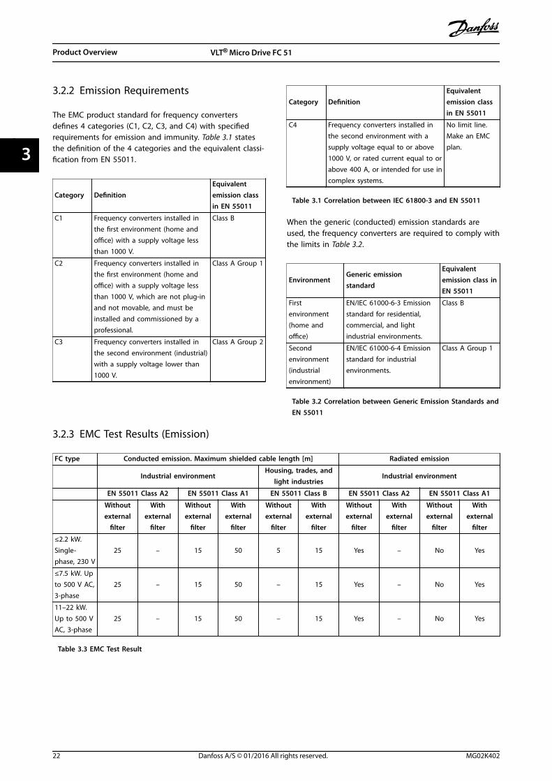
3.2.2 Emission Requirements
The EMC product standard for frequency convertersdefines 4 categories (C1, C2, C3, and C4) with specifiedrequirements for emission and immunity. Table 3.1 statesthe definition of the 4 categories and the equivalent classi-fication from EN 55011.
Category DefinitionEquivalentemission classin EN 55011
C1 Frequency converters installed inthe first environment (home andoffice) with a supply voltage lessthan 1000 V.
Class B
C2 Frequency converters installed inthe first environment (home andoffice) with a supply voltage lessthan 1000 V, which are not plug-inand not movable, and must beinstalled and commissioned by aprofessional.
Class A Group 1
C3 Frequency converters installed inthe second environment (industrial)with a supply voltage lower than1000 V.
Class A Group 2
Category DefinitionEquivalentemission classin EN 55011
C4 Frequency converters installed inthe second environment with asupply voltage equal to or above1000 V, or rated current equal to orabove 400 A, or intended for use incomplex systems.
No limit line.Make an EMCplan.
Table 3.1 Correlation between IEC 61800-3 and EN 55011
When the generic (conducted) emission standards areused, the frequency converters are required to comply withthe limits in Table 3.2.
EnvironmentGeneric emissionstandard
Equivalentemission class inEN 55011
Firstenvironment(home andoffice)
EN/IEC 61000-6-3 Emissionstandard for residential,commercial, and lightindustrial environments.
Class B
Secondenvironment(industrialenvironment)
EN/IEC 61000-6-4 Emissionstandard for industrialenvironments.
Class A Group 1
Table 3.2 Correlation between Generic Emission Standards andEN 55011
3.2.3 EMC Test Results (Emission)
FC type Conducted emission. Maximum shielded cable length [m] Radiated emission
Industrial environmentHousing, trades, and
light industriesIndustrial environment
EN 55011 Class A2 EN 55011 Class A1 EN 55011 Class B EN 55011 Class A2 EN 55011 Class A1
Withoutexternal
filter
Withexternal
filter
Withoutexternal
filter
Withexternal
filter
Withoutexternal
filter
Withexternal
filter
Withoutexternal
filter
Withexternal
filter
Withoutexternal
filter
Withexternal
filter
≤2.2 kW.Single-phase, 230 V
25 – 15 50 5 15 Yes – No Yes
≤7.5 kW. Upto 500 V AC,3-phase
25 – 15 50 – 15 Yes – No Yes
11–22 kW.Up to 500 VAC, 3-phase
25 – 15 50 – 15 Yes – No Yes
Table 3.3 EMC Test Result
Product Overview VLT® Micro Drive FC 51
22 Danfoss A/S © 01/2016 All rights reserved. MG02K402
33
3.2.4 Harmonics Emission Requirements
Equipment connected to the public supply network
NOTICEWithout a power option, the frequency converter maynot comply with harmonics emission requirements.
Options Definition
1 IEC/EN 61000-3-2 Class A for 3-phase balancedequipment (for professional equipment only up to 1kW total power).
2 IEC/EN 61000-3-12 Equipment 16 A-75 A and profes-sional equipment as from 1 kW up to 16 A phasecurrent.
Table 3.4 Harmonics Emission Requirements
3.2.5 Immunity Requirements
The immunity requirements for frequency convertersdepend on the environment where they are installed. Therequirements for the industrial environment are higherthan the requirements for the home and officeenvironment. All Danfoss frequency converters complywith the requirements for the industrial environment andtherefore comply also with the lower requirements forhome and office environment with a large safety margin.
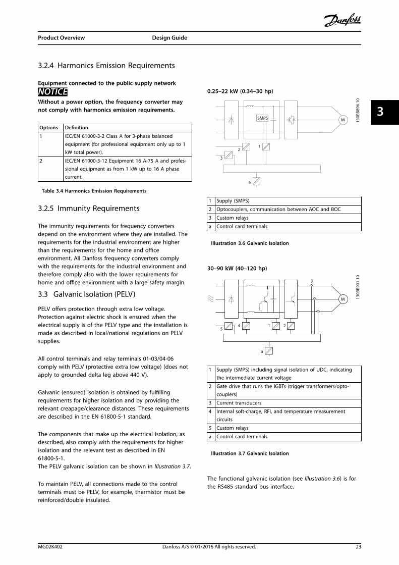
3.3 Galvanic Isolation (PELV)
PELV offers protection through extra low voltage.Protection against electric shock is ensured when theelectrical supply is of the PELV type and the installation ismade as described in local/national regulations on PELVsupplies.
All control terminals and relay terminals 01-03/04-06comply with PELV (protective extra low voltage) (does notapply to grounded delta leg above 440 V).
Galvanic (ensured) isolation is obtained by fulfillingrequirements for higher isolation and by providing therelevant creapage/clearance distances. These requirementsare described in the EN 61800-5-1 standard.
The components that make up the electrical isolation, asdescribed, also comply with the requirements for higherisolation and the relevant test as described in EN61800-5-1.The PELV galvanic isolation can be shown in Illustration 3.7.
To maintain PELV, all connections made to the controlterminals must be PELV, for example, thermistor must bereinforced/double insulated.
0.25–22 kW (0.34–30 hp)
SMPS
130B
B896
.10
12
3
a
M
1 Supply (SMPS)
2 Optocouplers, communication between AOC and BOC
3 Custom relays
a Control card terminals
Illustration 3.6 Galvanic Isolation
30–90 kW (40–120 hp)
130B
B901
.10
1
3
245
a
M
1 Supply (SMPS) including signal isolation of UDC, indicatingthe intermediate current voltage
2 Gate drive that runs the IGBTs (trigger transformers/opto-couplers)
3 Current transducers
4 Internal soft-charge, RFI, and temperature measurementcircuits
5 Custom relays
a Control card terminals
Illustration 3.7 Galvanic Isolation
The functional galvanic isolation (see Illustration 3.6) is forthe RS485 standard bus interface.
Product Overview Design Guide
MG02K402 Danfoss A/S © 01/2016 All rights reserved. 23
3 3
CAUTIONINSTALLATION AT HIGH ALTITUDEAt altitudes above 2000 m (6500 ft), contact Danfossregarding PELV.
3.4 Ground Leakage Current
WARNINGDISCHARGE TIMETouching the electrical parts could be fatal - even afterthe equipment has been disconnected from mains.Also make sure that other voltage inputs have beendisconnected, such as load sharing (linkage of DCintermediate circuit), and the motor connection forkinetic back-up.Before touching any electrical parts, wait at least theamount of time indicated in Table 2.1.Shorter time is allowed only if indicated on thenameplate for the specific unit.
WARNINGLEAKAGE CURRENT HAZARDLeakage currents exceed 3.5 mA. Failure to ground thefrequency converter properly can result in death orserious injury.
• Ensure the correct grounding of the equipmentby a certified electrical installer.
WARNINGRESIDUAL CURRENT DEVICE PROTECTIONThis product can cause a DC current in the protectiveconductor. Where a residual current device (RCD) is usedfor protection in case of direct or indirect contact, onlyan RCD of Type B is allowed on the supply side of thisproduct. Otherwise, apply another protective measure,such as separation from the environment by double orreinforced insulation, or isolation from the supply systemby a transformer. See also application note Protectionagainst Electrical Hazards.Protective grounding of the frequency converter and theuse of RCDs must always follow national and localregulations.
3.5 Extreme Running Conditions
Short circuit (motor phase-phase)Current measurement in each of the 3 motor phases or inthe DC-link, protects the frequency converter against shortcircuits. A short circuit between 2 output phases causes anovercurrent in the inverter. The inverter is turned offindividually when the short circuit current exceeds theallowed value (Alarm 16 Trip Lock).
For information about protecting the frequency converteragainst a short circuit at the load sharing and brakeoutputs, see chapter 6.6 Fuses.
Switching on the outputSwitching on the output between the motor and thefrequency converter is fully permitted. The frequencyconverter is not damaged in any way by switching on theoutput. However, fault messages may appear.
Motor-generated overvoltageThe voltage in the DC link is increased when the motoracts as a generator. This occurs in following cases:
• The load drives the motor (at constant outputfrequency from the frequency converter), that isthe load generates energy.
• During deceleration (ramp-down) if the inertiamoment is high, the friction is low, and the ramp-down time is too short for the energy to bedissipated as a loss in the frequency converter,the motor, and the installation.
• Incorrect slip compensation setting(parameter 1-62 Slip Compensation) may causehigher DC-link voltage.
The control unit may attempt to correct the ramp ifparameter 2-17 Over-voltage Control is enabled.The frequency converter turns off to protect the transistorsand the DC link capacitors when a certain voltage level isreached.
Mains drop-outDuring a mains drop-out, the frequency converter keepsrunning until the DC-link voltage drops below theminimum stop level, which is typically 15% below thefrequency converter's lowest rated supply voltage. Themains voltage before the drop-out and the motor loaddetermines how long it takes for the frequency converterto coast.
3.5.1 Motor Thermal Protection
Motor thermal protection can be provided in 2 ways.
Using a motor thermistor, via 1 of the following:
• Thermistor input on a standard AI.
• VLT® Sensor Input MCB 114.
• VLT® PTC Thermistor Card MCB 112.
The frequency converter monitors motor temperature asthe speed and load vary to detect overheating conditions.
The other method calculates motor temperature bymeasuring current, frequency, and operating time. Thefrequency converter shows the thermal load on the motorin percentage and can issue a warning at a programmable
Product Overview VLT® Micro Drive FC 51
24 Danfoss A/S © 01/2016 All rights reserved. MG02K402
33
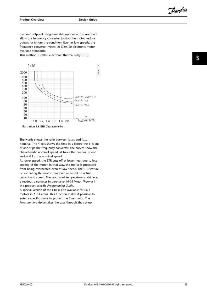
overload setpoint. Programmable options at the overloadallow the frequency converter to stop the motor, reduceoutput, or ignore the condition. Even at low speeds, thefrequency converter meets I2t Class 20 electronic motoroverload standards.This method is called electronic thermal relay (ETR).
1.21.0 1.4
30
1020
10060
4050
1.81.6 2.0
2000
500
200
400300
1000600
t [s]
175Z
A05
2.12
fOUT = 2 x f M,N
fOUT = 0.2 x f M,N
fOUT = 1 x f M,N(par. 1-23)
IMN(par. 1-24)IM
Illustration 3.8 ETR Characteristics
The X-axis shows the ratio between Imotor and Imotor
nominal. The Y axis shows the time in s before the ETR cutof and trips the frequency converter. The curves show thecharacteristic nominal speed, at twice the nominal speedand at 0.2 x the nominal speed.At lower speed, the ETR cuts off at lower heat due to lesscooling of the motor. In that way, the motor is protectedfrom being overheated even at low speed. The ETR featureis calculating the motor temperature based on actualcurrent and speed. The calculated temperature is visible asa readout parameter in parameter 16-18 Motor Thermal inthe product-specific Programming Guide.A special version of the ETR is also available for EX-emotors in ATEX areas. This function makes it possible toenter a specific curve to protect the Ex-e motor. TheProgramming Guide takes the user through the set-up.
Product Overview Design Guide
MG02K402 Danfoss A/S © 01/2016 All rights reserved. 25
3 3
4 Selection
4.1 Options and Accessories
4.1.1 Local Control Panel (LCP)
For detailed information on programming, see VLT® MicroDrive FC 51 Programming Guide.
NOTICEThe frequency converter can also be programmed from aPC via RS485 port by installing the MCT 10 Set-upSoftware.This software can either be ordered using code number130B1000 or downloaded from the Danfoss website:www.danfoss.com/BusinessAreas/DrivesSolutions/software-download
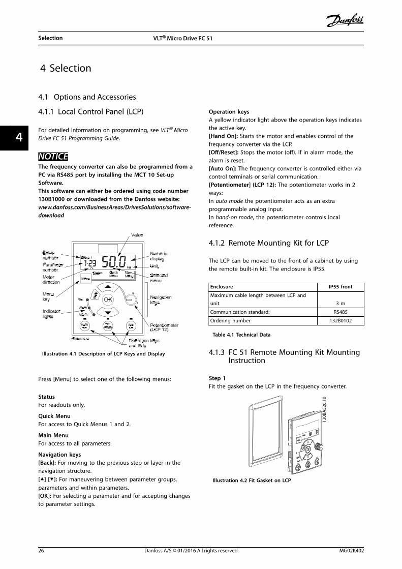
Illustration 4.1 Description of LCP Keys and Display
Press [Menu] to select one of the following menus:
StatusFor readouts only.
Quick MenuFor access to Quick Menus 1 and 2.
Main MenuFor access to all parameters.
Navigation keys[Back]: For moving to the previous step or layer in thenavigation structure.[▲] [▼]: For maneuvering between parameter groups,parameters and within parameters.[OK]: For selecting a parameter and for accepting changesto parameter settings.
Operation keysA yellow indicator light above the operation keys indicatesthe active key.[Hand On]: Starts the motor and enables control of thefrequency converter via the LCP.[Off/Reset]: Stops the motor (off). If in alarm mode, thealarm is reset.[Auto On]: The frequency converter is controlled either viacontrol terminals or serial communication.[Potentiometer] (LCP 12): The potentiometer works in 2ways:In auto mode the potentiometer acts as an extraprogrammable analog input.In hand-on mode, the potentiometer controls localreference.
4.1.2 Remote Mounting Kit for LCP
The LCP can be moved to the front of a cabinet by usingthe remote built-in kit. The enclosure is IP55.
Enclosure IP55 front
Maximum cable length between LCP andunit 3 m
Communication standard: RS485
Ordering number 132B0102
Table 4.1 Technical Data
4.1.3 FC 51 Remote Mounting Kit MountingInstruction
Step 1Fit the gasket on the LCP in the frequency converter.
130B
A52
6.10
Illustration 4.2 Fit Gasket on LCP
Selection VLT® Micro Drive FC 51
26 Danfoss A/S © 01/2016 All rights reserved. MG02K402
44
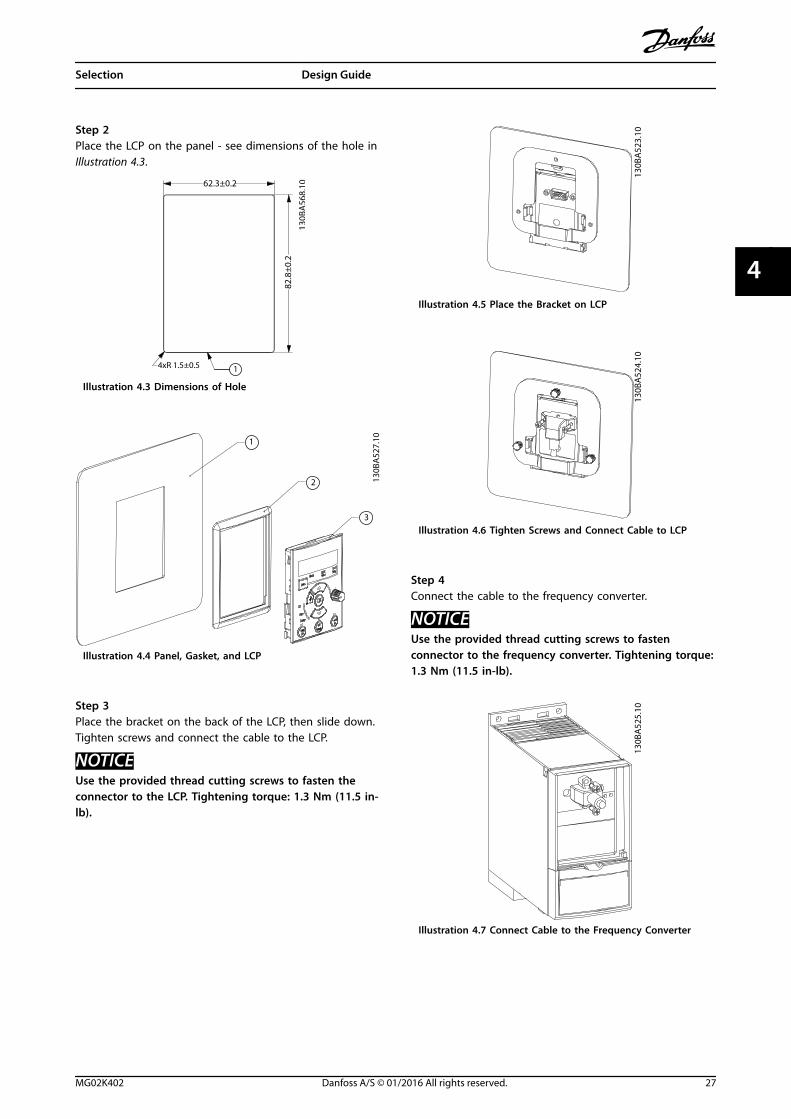
Step 2Place the LCP on the panel - see dimensions of the hole inIllustration 4.3.
62.3±0.2
82.8
±0.2
4xR 1.5±0.5 1
130B
A56
8.10
Illustration 4.3 Dimensions of Hole
1
2
3
130B
A52
7.10
Illustration 4.4 Panel, Gasket, and LCP
Step 3Place the bracket on the back of the LCP, then slide down.Tighten screws and connect the cable to the LCP.
NOTICEUse the provided thread cutting screws to fasten theconnector to the LCP. Tightening torque: 1.3 Nm (11.5 in-lb).
130B
A52
3.10
Illustration 4.5 Place the Bracket on LCP
130B
A52
4.10
Illustration 4.6 Tighten Screws and Connect Cable to LCP
Step 4Connect the cable to the frequency converter.
NOTICEUse the provided thread cutting screws to fastenconnector to the frequency converter. Tightening torque:1.3 Nm (11.5 in-lb).
130B
A52
5.10
Illustration 4.7 Connect Cable to the Frequency Converter
Selection Design Guide
MG02K402 Danfoss A/S © 01/2016 All rights reserved. 27
4 4
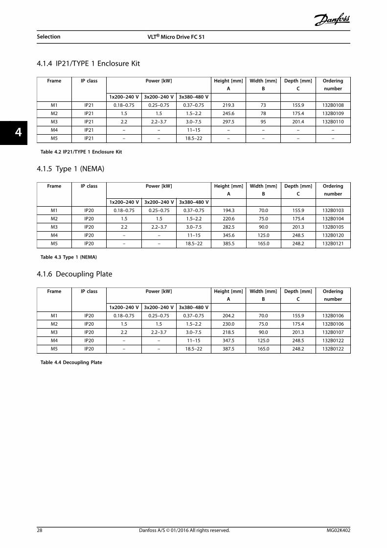
4.1.4 IP21/TYPE 1 Enclosure Kit
Frame IP class Power [kW] Height [mm]A
Width [mm]B
Depth [mm]C
Orderingnumber
1x200–240 V 3x200–240 V 3x380–480 V
M1 IP21 0.18–0.75 0.25–0.75 0.37–0.75 219.3 73 155.9 132B0108
M2 IP21 1.5 1.5 1.5–2.2 245.6 78 175.4 132B0109
M3 IP21 2.2 2.2–3.7 3.0–7.5 297.5 95 201.4 132B0110
M4 IP21 – – 11–15 – – – –
M5 IP21 – – 18.5–22 – – – –
Table 4.2 IP21/TYPE 1 Enclosure Kit
4.1.5 Type 1 (NEMA)
Frame IP class Power [kW] Height [mm]A
Width [mm]B
Depth [mm]C
Orderingnumber
1x200–240 V 3x200–240 V 3x380–480 V
M1 IP20 0.18–0.75 0.25–0.75 0.37–0.75 194.3 70.0 155.9 132B0103
M2 IP20 1.5 1.5 1.5–2.2 220.6 75.0 175.4 132B0104
M3 IP20 2.2 2.2–3.7 3.0–7.5 282.5 90.0 201.3 132B0105
M4 IP20 – – 11–15 345.6 125.0 248.5 132B0120
M5 IP20 – – 18.5–22 385.5 165.0 248.2 132B0121
Table 4.3 Type 1 (NEMA)
4.1.6 Decoupling Plate
Frame IP class Power [kW] Height [mm]A
Width [mm]B
Depth [mm]C
Orderingnumber
1x200–240 V 3x200–240 V 3x380–480 V
M1 IP20 0.18–0.75 0.25–0.75 0.37–0.75 204.2 70.0 155.9 132B0106
M2 IP20 1.5 1.5 1.5–2.2 230.0 75.0 175.4 132B0106
M3 IP20 2.2 2.2–3.7 3.0–7.5 218.5 90.0 201.3 132B0107
M4 IP20 – – 11–15 347.5 125.0 248.5 132B0122
M5 IP20 – – 18.5–22 387.5 165.0 248.2 132B0122
Table 4.4 Decoupling Plate
Selection VLT® Micro Drive FC 51
28 Danfoss A/S © 01/2016 All rights reserved. MG02K402
44
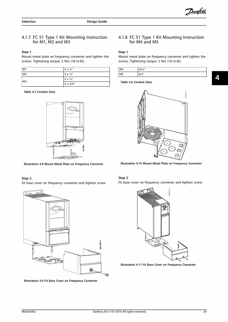
4.1.7 FC 51 Type 1 Kit Mounting Instructionfor M1, M2 and M3
Step 1Mount metal plate on frequency converter and tighten thescrews. Tightening torque: 2 Nm (18 in-lb).
M1 4 x ½”
M2 5 x ½“
M32 x ½”
3 x 3/4”
Table 4.5 Conduit Sizes
Illustration 4.8 Mount Metal Plate on Frequency Converter
Step 2Fit base cover on frequency converter and tighten screw.
Illustration 4.9 Fit Base Cover on Frequency Converter
4.1.8 FC 51 Type 1 Kit Mounting Instructionfor M4 and M5
Step 1Mount metal plate on frequency converter and tighten thescrews. Tightening torque: 2 Nm (18 in-lb).
M4 3x½”
M5 3x1“
Table 4.6 Conduit Sizes
Illustration 4.10 Mount Metal Plate on Frequency Converter
Step 2Fit base cover on frequency converter and tighten screw.
Illustration 4.11 Fit Base Cover on Frequency Converter
Selection Design Guide
MG02K402 Danfoss A/S © 01/2016 All rights reserved. 29
4 4
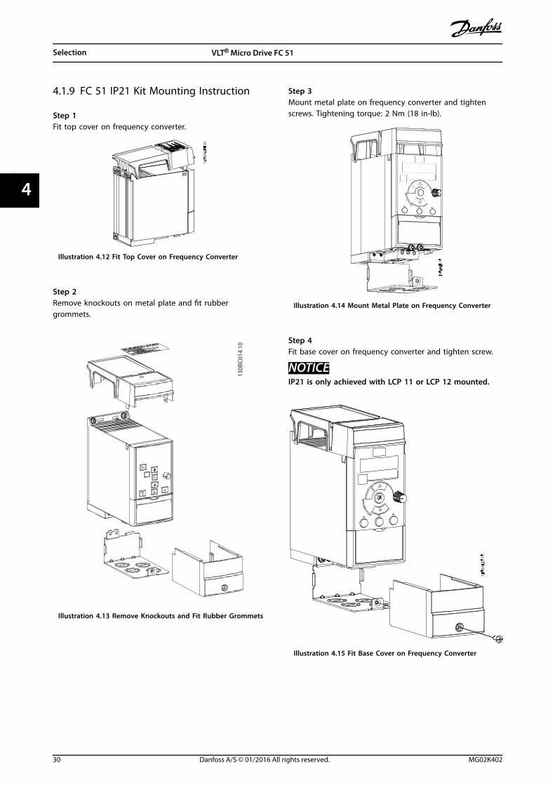
4.1.9 FC 51 IP21 Kit Mounting Instruction
Step 1Fit top cover on frequency converter.
Illustration 4.12 Fit Top Cover on Frequency Converter
Step 2Remove knockouts on metal plate and fit rubbergrommets.
130B
C01
4.10
Illustration 4.13 Remove Knockouts and Fit Rubber Grommets
Step 3Mount metal plate on frequency converter and tightenscrews. Tightening torque: 2 Nm (18 in-lb).
Illustration 4.14 Mount Metal Plate on Frequency Converter
Step 4Fit base cover on frequency converter and tighten screw.
NOTICEIP21 is only achieved with LCP 11 or LCP 12 mounted.
Illustration 4.15 Fit Base Cover on Frequency Converter
Selection VLT® Micro Drive FC 51
30 Danfoss A/S © 01/2016 All rights reserved. MG02K402
44
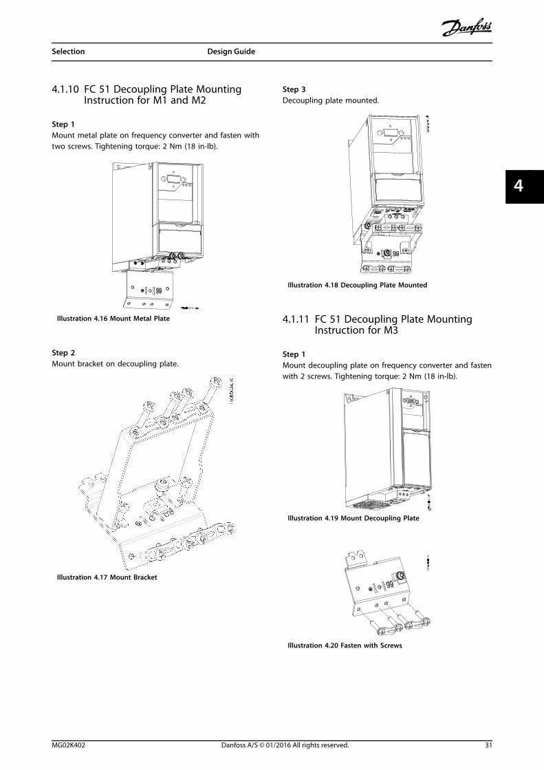
4.1.10 FC 51 Decoupling Plate MountingInstruction for M1 and M2
Step 1Mount metal plate on frequency converter and fasten withtwo screws. Tightening torque: 2 Nm (18 in-lb).
Illustration 4.16 Mount Metal Plate
Step 2Mount bracket on decoupling plate.
Illustration 4.17 Mount Bracket
Step 3Decoupling plate mounted.
Illustration 4.18 Decoupling Plate Mounted
4.1.11 FC 51 Decoupling Plate MountingInstruction for M3
Step 1Mount decoupling plate on frequency converter and fastenwith 2 screws. Tightening torque: 2 Nm (18 in-lb).
Illustration 4.19 Mount Decoupling Plate
Illustration 4.20 Fasten with Screws
Selection Design Guide
MG02K402 Danfoss A/S © 01/2016 All rights reserved. 31
4 4
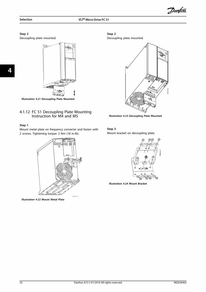
Step 2Decoupling plate mounted.
Illustration 4.21 Decoupling Plate Mounted
4.1.12 FC 51 Decoupling Plate MountingInstruction for M4 and M5
Step 1Mount metal plate on frequency converter and fasten with2 screws. Tightening torque: 2 Nm (18 in-lb).
Illustration 4.22 Mount Metal Plate
Step 2Decoupling plate mounted.
Illustration 4.23 Decoupling Plate Mounted
Step 3Mount bracket on decoupling plate.
Illustration 4.24 Mount Bracket
Selection VLT® Micro Drive FC 51
32 Danfoss A/S © 01/2016 All rights reserved. MG02K402
44
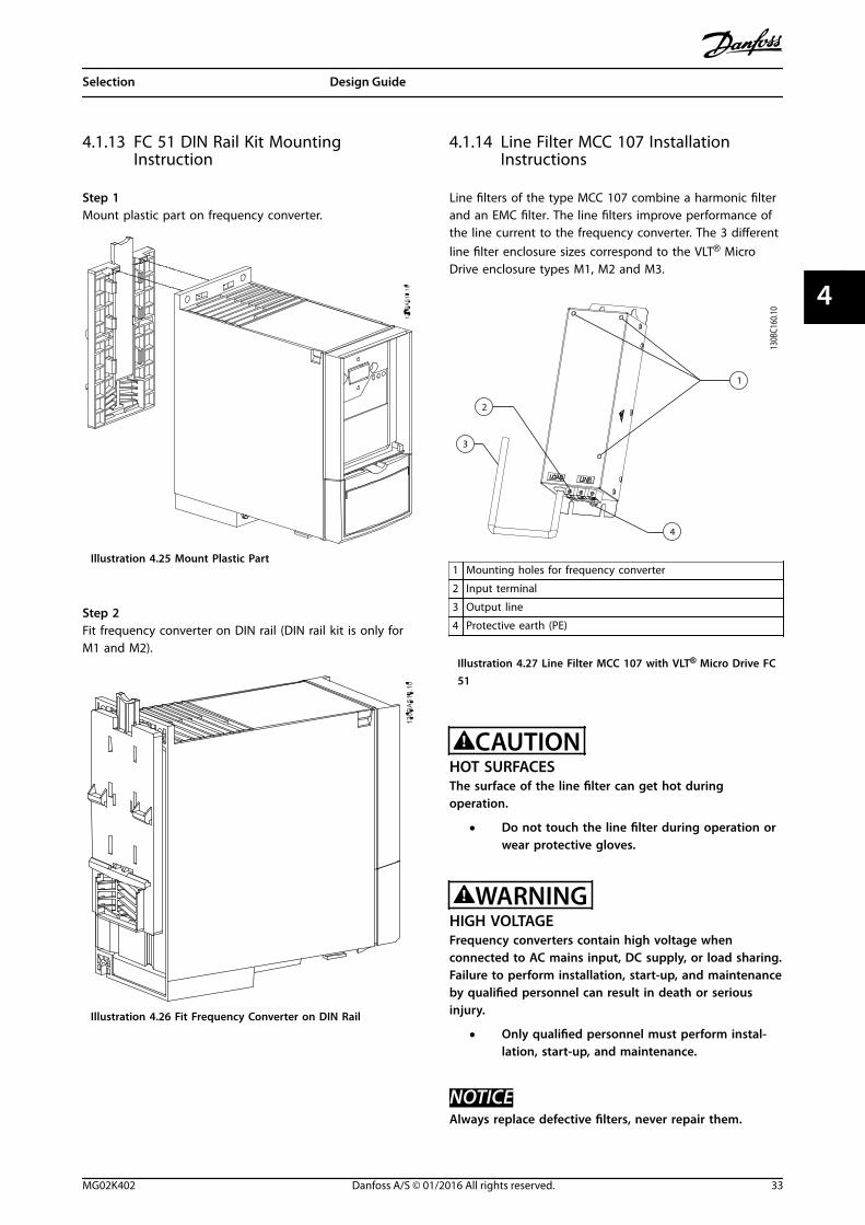
4.1.13 FC 51 DIN Rail Kit MountingInstruction
Step 1Mount plastic part on frequency converter.
Illustration 4.25 Mount Plastic Part
Step 2Fit frequency converter on DIN rail (DIN rail kit is only forM1 and M2).
Illustration 4.26 Fit Frequency Converter on DIN Rail
4.1.14 Line Filter MCC 107 InstallationInstructions
Line filters of the type MCC 107 combine a harmonic filterand an EMC filter. The line filters improve performance ofthe line current to the frequency converter. The 3 differentline filter enclosure sizes correspond to the VLT® MicroDrive enclosure types M1, M2 and M3.
4
130B
C160
.10
2
3
1
1 Mounting holes for frequency converter
2 Input terminal
3 Output line
4 Protective earth (PE)
Illustration 4.27 Line Filter MCC 107 with VLT® Micro Drive FC51
CAUTIONHOT SURFACESThe surface of the line filter can get hot duringoperation.
• Do not touch the line filter during operation orwear protective gloves.
WARNINGHIGH VOLTAGEFrequency converters contain high voltage whenconnected to AC mains input, DC supply, or load sharing.Failure to perform installation, start-up, and maintenanceby qualified personnel can result in death or seriousinjury.
• Only qualified personnel must perform instal-lation, start-up, and maintenance.
NOTICEAlways replace defective filters, never repair them.
Selection Design Guide
MG02K402 Danfoss A/S © 01/2016 All rights reserved. 33
4 4
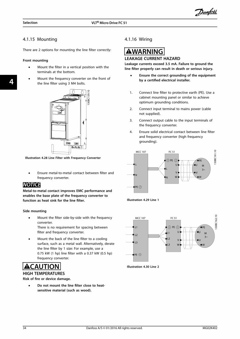
4.1.15 Mounting
There are 2 options for mounting the line filter correctly:
Front mounting
• Mount the filter in a vertical position with theterminals at the bottom.
• Mount the frequency converter on the front ofthe line filter using 3 M4 bolts.
130B
C15
9.10
Illustration 4.28 Line Filter with Frequency Converter
• Ensure metal-to-metal contact between filter andfrequency converter.
NOTICEMetal-to-metal contact improves EMC performance andenables the base plate of the frequency converter tofunction as heat sink for the line filter.
Side mounting
• Mount the filter side-by-side with the frequencyconverter.There is no requirement for spacing betweenfilter and frequency converter.
• Mount the back of the line filter to a coolingsurface, such as a metal wall. Alternatively, deratethe line filter by 1 size: For example, use a0.75 kW (1 hp) line filter with a 0.37 kW (0.5 hp)frequency converter.
CAUTIONHIGH TEMPERATURESRisk of fire or device damage.
• Do not mount the line filter close to heat-sensitive material (such as wood).
4.1.16 Wiring
WARNINGLEAKAGE CURRENT HAZARDLeakage currents exceed 3.5 mA. Failure to ground theline filter properly can result in death or serious injury.
• Ensure the correct grounding of the equipmentby a certified electrical installer.
1. Connect line filter to protective earth (PE). Use acabinet mounting panel or similar to achieveoptimum grounding conditions.
2. Connect input terminal to mains power (cablenot supplied).
3. Connect output cable to the input terminals ofthe frequency converter.
4. Ensure solid electrical contact between line filterand frequency converter (high frequencygrounding).
PE
U
V
W
L
N
L
N
PE
M3~
PE
U
V
W
MCC 107 FC 51
130B
C161
.10
Illustration 4.29 Line 1
PE
U
V
W
L1
L1
PE
M3~
PE
U
V
W
MCC 107 FC 51
L2
L3L2
L3
130B
C162
.10
Illustration 4.30 Line 2
Selection VLT® Micro Drive FC 51
34 Danfoss A/S © 01/2016 All rights reserved. MG02K402
44
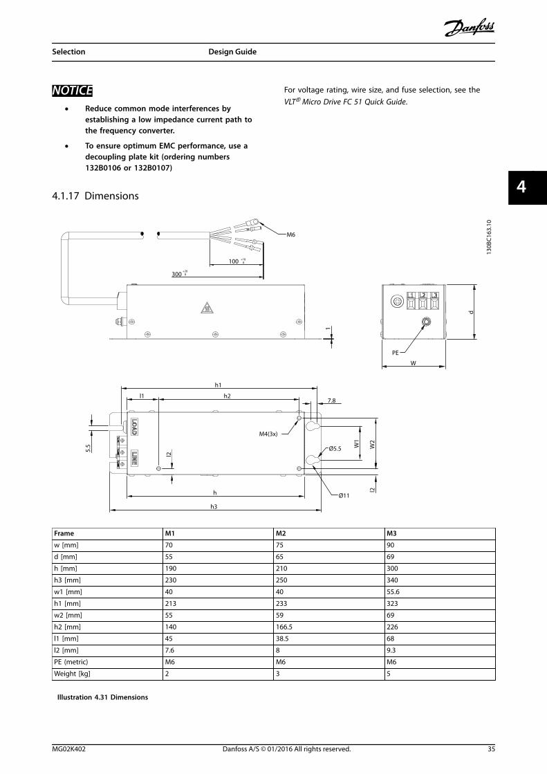
NOTICE• Reduce common mode interferences by
establishing a low impedance current path tothe frequency converter.
• To ensure optimum EMC performance, use adecoupling plate kit (ordering numbers132B0106 or 132B0107)
For voltage rating, wire size, and fuse selection, see theVLT® Micro Drive FC 51 Quick Guide.
4.1.17 Dimensions
100 +10 0
300+20
0
M6
1
W
PE
d
LOA
DL
INE
5.5
h1
l1 h27.8
W1
W2
l2h
l2
h3
Ø11
Ø5.5
M4(3x)
130B
C163
.10
Frame M1 M2 M3
w [mm] 70 75 90
d [mm] 55 65 69
h [mm] 190 210 300
h3 [mm] 230 250 340
w1 [mm] 40 40 55.6
h1 [mm] 213 233 323
w2 [mm] 55 59 69
h2 [mm] 140 166.5 226
l1 [mm] 45 38.5 68
l2 [mm] 7.6 8 9.3
PE (metric) M6 M6 M6
Weight [kg] 2 3 5
Illustration 4.31 Dimensions
Selection Design Guide
MG02K402 Danfoss A/S © 01/2016 All rights reserved. 35
4 4
4.2 Special Conditions
4.2.1 Purpose of Derating
Consider the purpose of derating when using thefrequency converter at low air pressure (heights), at lowspeeds, with long motor cables, cables with a large cross-section, or at high ambient temperature. The requiredaction is described in this section.
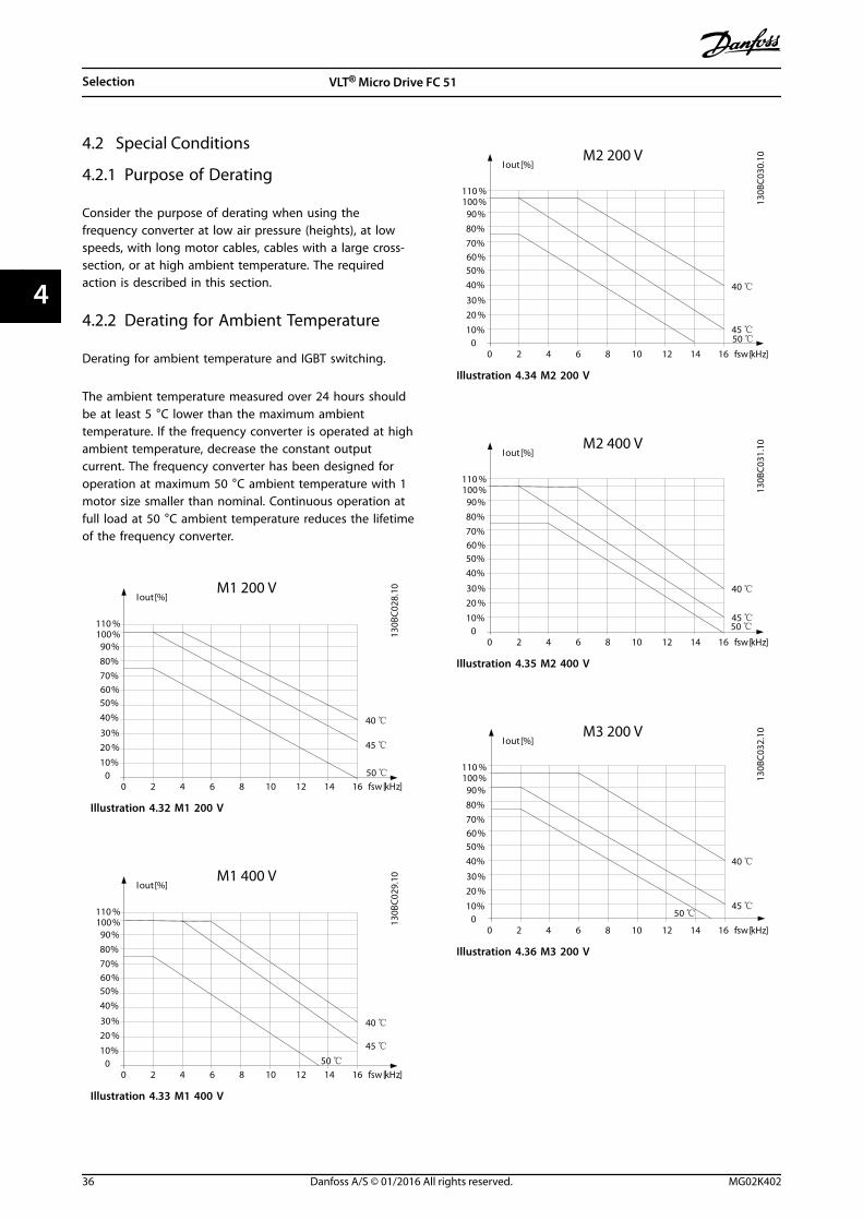
4.2.2 Derating for Ambient Temperature
Derating for ambient temperature and IGBT switching.
The ambient temperature measured over 24 hours shouldbe at least 5 °C lower than the maximum ambienttemperature. If the frequency converter is operated at highambient temperature, decrease the constant outputcurrent. The frequency converter has been designed foroperation at maximum 50 °C ambient temperature with 1motor size smaller than nominal. Continuous operation atfull load at 50 °C ambient temperature reduces the lifetimeof the frequency converter.
M1 200 V
fsw[kHz]20 64 108 14120
10 %
20 %
30 %
40 %
50 %60 %70 %
80 %
90 %100 %110 %
Iout [%]
16
40 ℃
45 ℃
50 ℃
130B
C02
8.10
Illustration 4.32 M1 200 V
M1 400 V
fsw[kHz]20 64 108 14120
10 %
20 %
30 %
40 %
50 %60 %70 %
80 %
90 %100 %110 %
Iout [%]
16
40 ℃
45 ℃
50 ℃
130B
C02
9.10
Illustration 4.33 M1 400 V
M2 200 V
fsw[kHz]20 64 108 14120
10 %
20 %
30 %
40 %
50 %60 %70 %
80 %
90 %100 %110 %
Iout [%]
16
40 ℃
45 ℃50 ℃
130B
C03
0.10
Illustration 4.34 M2 200 V
M2 400 V
fsw[kHz]20 64 108 14120
10 %
20 %
30 %
40 %
50 %60 %70 %
80 %
90 %100 %110 %
Iout [%]
16
40 ℃
45 ℃50 ℃
130B
C03
1.10
Illustration 4.35 M2 400 V
M3 200 V
fsw[kHz]20 64 108 14120
10 %
20 %
30 %
40 %
50 %60 %70 %
80 %
90 %100 %110 %
Iout [%]
16
40 ℃
45 ℃50 ℃
130B
C03
2.10
Illustration 4.36 M3 200 V
Selection VLT® Micro Drive FC 51
36 Danfoss A/S © 01/2016 All rights reserved. MG02K402
44
M3 400 V
fsw[kHz]20 64 108 14120
10 %
20 %
30 %
40 %
50 %60 %70 %
80 %
90 %100 %110 %
Iout [%]
16
40 ℃
45 ℃50 ℃
130B
C03
3.10
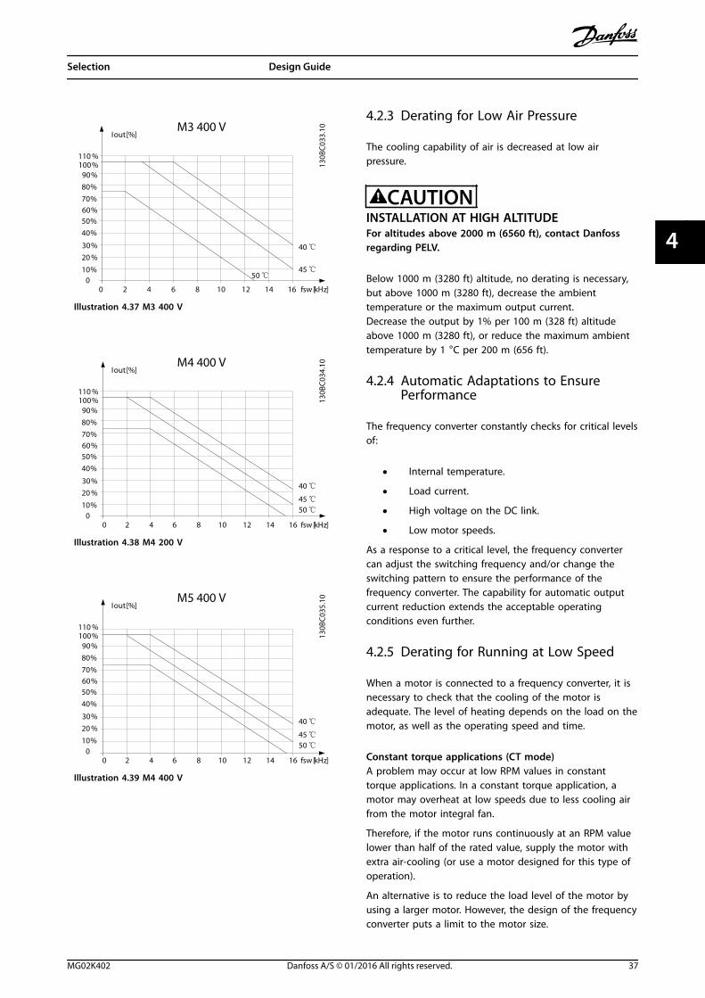
Illustration 4.37 M3 400 V
M4 400 V
fsw[kHz]20 64 108 14120
10 %
20 %
30 %
40 %
50 %60 %70 %
80 %
90 %100 %110 %
Iout [%]
16
40 ℃
45 ℃50 ℃
130B
C03
4.10
Illustration 4.38 M4 200 V
M5 400 V
fsw[kHz]20 64 108 14120
10 %
20 %
30 %
40 %
50 %60 %70 %
80 %
90 %100 %110 %
Iout [%]
16
40 ℃
45 ℃50 ℃
130B
C03
5.10
Illustration 4.39 M4 400 V
4.2.3 Derating for Low Air Pressure
The cooling capability of air is decreased at low airpressure.
CAUTIONINSTALLATION AT HIGH ALTITUDEFor altitudes above 2000 m (6560 ft), contact Danfossregarding PELV.
Below 1000 m (3280 ft) altitude, no derating is necessary,but above 1000 m (3280 ft), decrease the ambienttemperature or the maximum output current.Decrease the output by 1% per 100 m (328 ft) altitudeabove 1000 m (3280 ft), or reduce the maximum ambienttemperature by 1 °C per 200 m (656 ft).
4.2.4 Automatic Adaptations to EnsurePerformance
The frequency converter constantly checks for critical levelsof:
• Internal temperature.
• Load current.
• High voltage on the DC link.
• Low motor speeds.
As a response to a critical level, the frequency convertercan adjust the switching frequency and/or change theswitching pattern to ensure the performance of thefrequency converter. The capability for automatic outputcurrent reduction extends the acceptable operatingconditions even further.
4.2.5 Derating for Running at Low Speed
When a motor is connected to a frequency converter, it isnecessary to check that the cooling of the motor isadequate. The level of heating depends on the load on themotor, as well as the operating speed and time.
Constant torque applications (CT mode)A problem may occur at low RPM values in constanttorque applications. In a constant torque application, amotor may overheat at low speeds due to less cooling airfrom the motor integral fan.
Therefore, if the motor runs continuously at an RPM valuelower than half of the rated value, supply the motor withextra air-cooling (or use a motor designed for this type ofoperation).
An alternative is to reduce the load level of the motor byusing a larger motor. However, the design of the frequencyconverter puts a limit to the motor size.
Selection Design Guide
MG02K402 Danfoss A/S © 01/2016 All rights reserved. 37
4 4
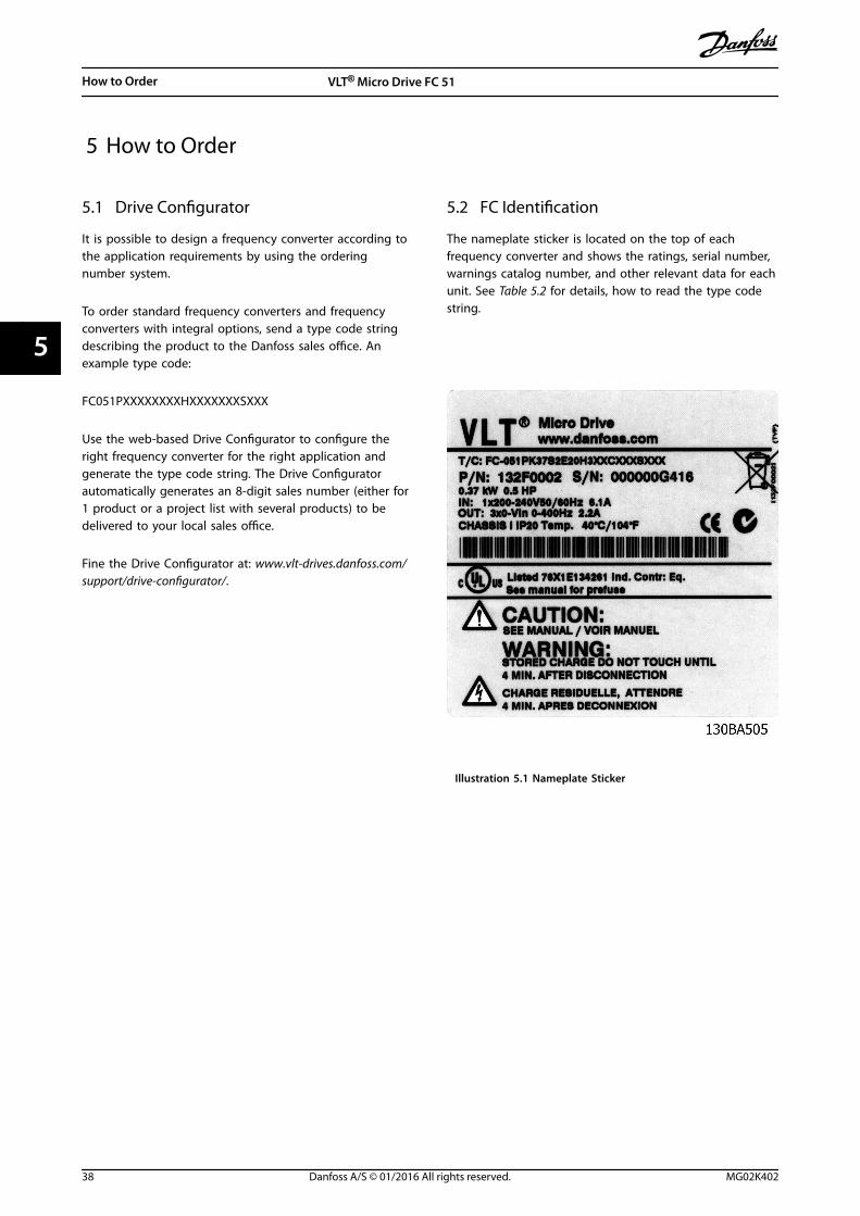
5 How to Order
5.1 Drive Configurator
It is possible to design a frequency converter according tothe application requirements by using the orderingnumber system.
To order standard frequency converters and frequencyconverters with integral options, send a type code stringdescribing the product to the Danfoss sales office. Anexample type code:
FC051PXXXXXXXXHXXXXXXXSXXX
Use the web-based Drive Configurator to configure theright frequency converter for the right application andgenerate the type code string. The Drive Configuratorautomatically generates an 8-digit sales number (either for1 product or a project list with several products) to bedelivered to your local sales office.
Fine the Drive Configurator at: www.vlt-drives.danfoss.com/support/drive-configurator/.
5.2 FC Identification
The nameplate sticker is located on the top of eachfrequency converter and shows the ratings, serial number,warnings catalog number, and other relevant data for eachunit. See Table 5.2 for details, how to read the type codestring.
Illustration 5.1 Nameplate Sticker
How to Order VLT® Micro Drive FC 51
38 Danfoss A/S © 01/2016 All rights reserved. MG02K402
55
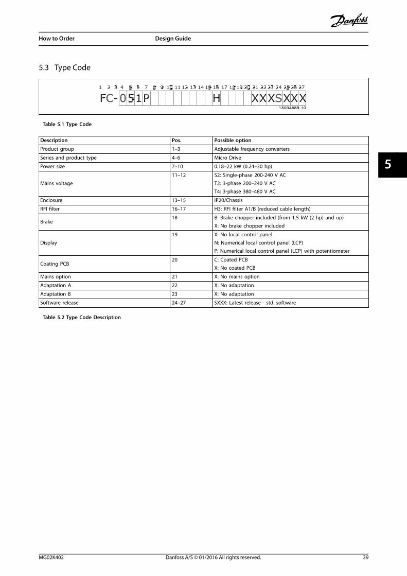
5.3 Type Code
Table 5.1 Type Code
Description Pos. Possible option
Product group 1–3 Adjustable frequency converters
Series and product type 4–6 Micro Drive
Power size 7–10 0.18–22 kW (0.24–30 hp)
Mains voltage11–12 S2: Single-phase 200-240 V AC
T2: 3-phase 200–240 V ACT4: 3-phase 380–480 V AC
Enclosure 13–15 IP20/Chassis
RFI filter 16–17 H3: RFI filter A1/B (reduced cable length)
Brake18 B: Brake chopper included (from 1.5 kW (2 hp) and up)
X: No brake chopper included
Display19 X: No local control panel
N: Numerical local control panel (LCP)P: Numerical local control panel (LCP) with potentiometer
Coating PCB20 C: Coated PCB
X: No coated PCB
Mains option 21 X: No mains option
Adaptation A 22 X: No adaptation
Adaptation B 23 X: No adaptation
Software release 24–27 SXXX: Latest release - std. software
Table 5.2 Type Code Description
How to Order Design Guide
MG02K402 Danfoss A/S © 01/2016 All rights reserved. 39
5 5
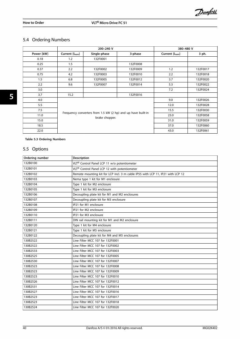
5.4 Ordering Numbers
200–240 V 380–480 V
Power [kW] Current [lnom] Single-phase 3-phase Current [lnom] 3 ph.
0.18 1.2 132F0001
0.25 1.5 132F0008
0.37 2.2 132F0002 132F0009 1.2 132F0017
0.75 4.2 132F0003 132F0010 2.2 132F0018
1.5 6.8 132F0005 132F0012 3.7 132F0020
2.2 9.6 132F0007 132F0014 5.3 132F0022
3.0 7.2 132F0024
3.7 15.2 132F0016
4.0
Frequency converters from 1.5 kW (2 hp) and up have built-inbrake chopper.
9.0 132F0026
5.5 12.0 132F0028
7.5 15.5 132F0030
11.0 23.0 132F0058
15.0 31.0 132F0059
18.5 37.0 132F0060
22.0 43.0 132F0061
Table 5.3 Ordering Numbers
5.5 Options
Ordering number Description
132B0100 VLT® Control Panel LCP 11 w/o potentiometer
132B0101 VLT® Control Panel LCP 12 with potentiometer
132B0102 Remote mounting kit for LCP incl. 3 m cable IP55 with LCP 11, IP21 with LCP 12
132B0103 Nema type 1 kit for M1 enclosure
132B0104 Type 1 kit for M2 enclosure
132B0105 Type 1 kit for M3 enclosure
132B0106 Decoupling plate kit for M1 and M2 enclosures
132B0107 Decoupling plate kit for M3 enclosure
132B0108 IP21 for M1 enclosure
132B0109 IP21 for M2 enclosure
132B0110 IP21 for M3 enclosure
132B0111 DIN rail mounting kit for M1 and M2 enclosure
132B0120 Type 1 kit for M4 enclosure
132B0121 Type 1 kit for M5 enclosure
132B0122 Decoupling plate kit for M4 and M5 enclosures
130B2522 Line Filter MCC 107 for 132F0001
130B2522 Line Filter MCC 107 for 132F0002
130B2533 Line Filter MCC 107 for 132F0003
130B2525 Line Filter MCC 107 for 132F0005
130B2530 Line Filter MCC 107 for 132F0007
130B2523 Line Filter MCC 107 for 132F0008
130B2523 Line Filter MCC 107 for 132F0009
130B2523 Line Filter MCC 107 for 132F0010
130B2526 Line Filter MCC 107 for 132F0012
130B2531 Line Filter MCC 107 for 132F0014
130B2527 Line Filter MCC 107 for 132F0016
130B2523 Line Filter MCC 107 for 132F0017
130B2523 Line Filter MCC 107 for 132F0018
130B2524 Line Filter MCC 107 for 132F0020
How to Order VLT® Micro Drive FC 51
40 Danfoss A/S © 01/2016 All rights reserved. MG02K402
55
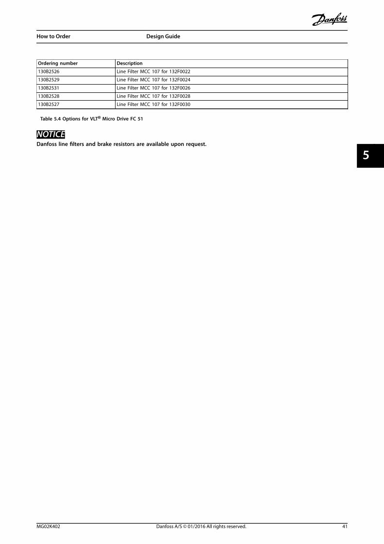
Ordering number Description
130B2526 Line Filter MCC 107 for 132F0022
130B2529 Line Filter MCC 107 for 132F0024
130B2531 Line Filter MCC 107 for 132F0026
130B2528 Line Filter MCC 107 for 132F0028
130B2527 Line Filter MCC 107 for 132F0030
Table 5.4 Options for VLT® Micro Drive FC 51
NOTICEDanfoss line filters and brake resistors are available upon request.
How to Order Design Guide
MG02K402 Danfoss A/S © 01/2016 All rights reserved. 41
5 5
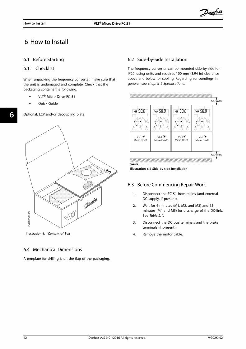
6 How to Install
6.1 Before Starting
6.1.1 Checklist
When unpacking the frequency converter, make sure thatthe unit is undamaged and complete. Check that thepackaging contains the following:
• VLT® Micro Drive FC 51
• Quick Guide
Optional: LCP and/or decoupling plate.
Illustration 6.1 Content of Box
6.2 Side-by-Side Installation
The frequency converter can be mounted side-by-side forIP20 rating units and requires 100 mm (3.94 in) clearanceabove and below for cooling. Regarding surroundings ingeneral, see chapter 9 Specifications.
Illustration 6.2 Side-by-side Installation
6.3 Before Commencing Repair Work
1. Disconnect the FC 51 from mains (and externalDC supply, if present).
2. Wait for 4 minutes (M1, M2, and M3) and 15minutes (M4 and M5) for discharge of the DC-link.See Table 2.1.
3. Disconnect the DC bus terminals and the braketerminals (if present).
4. Remove the motor cable.
6.4 Mechanical Dimensions
A template for drilling is on the flap of the packaging.
How to Install VLT® Micro Drive FC 51
42 Danfoss A/S © 01/2016 All rights reserved. MG02K402
66
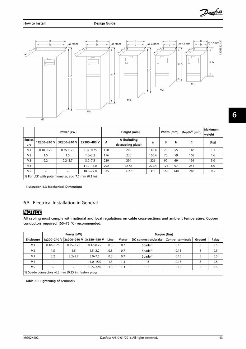
B
a A a A
a A
a Aa A
C C C C C
bBb
Bb
Bb
BbØ 7mm
M5
M4
M3
M2
M1
Ø 7mm Ø 5.5mm Ø 4.5mm
130B
B321
.11
Ø 4.5mm
Power [kW] Height [mm] Width [mm] Depth1) [mm]Maximumweight
Enclosure
1X200–240 V 3X200–240 V 3X380–480 V AA (including
decoupling plate)a B b C [kg]
M1 0.18–0.75 0.25–0.75 0.37–0.75 150 205 140.4 70 55 148 1.1
M2 1.5 1.5 1.5–2.2 176 230 166.4 75 59 168 1.6
M3 2.2 2.2–3.7 3.0–7.5 239 294 226 90 69 194 3.0
M4 – – 11.0–15.0 292 347.5 272.4 125 97 241 6.0
M5 – – 18.5–22.0 335 387.5 315 165 140 248 9.5
1) For LCP with potentiometer, add 7.6 mm (0.3 in).
Illustration 6.3 Mechanical Dimensions
6.5 Electrical Installation in General
NOTICEAll cabling must comply with national and local regulations on cable cross-sections and ambient temperature. Copperconductors required, (60–75 °C) recommended.
Power [kW] Torque [Nm]
Enclosure 1x200–240 V 3x200–240 V 3x380–480 V Line Motor DC connection/brake Control terminals Ground Relay
M1 0.18–0.75 0.25–0.75 0.37–0.75 0.8 0.7 Spade1) 0.15 3 0.5
M2 1.5 1.5 1.5–2.2 0.8 0.7 Spade1) 0.15 3 0.5
M3 2.2 2.2–3.7 3.0–7.5 0.8 0.7 Spade1) 0.15 3 0.5
M4 – – 11.0–15.0 1.3 1.3 1.3 0.15 3 0.5
M5 – – 18.5–22.0 1.3 1.3 1.3 0.15 3 0.5
1) Spade connectors (6.3 mm (0.25 in) Faston plugs)
Table 6.1 Tightening of Terminals
How to Install Design Guide
MG02K402 Danfoss A/S © 01/2016 All rights reserved. 43
6 6
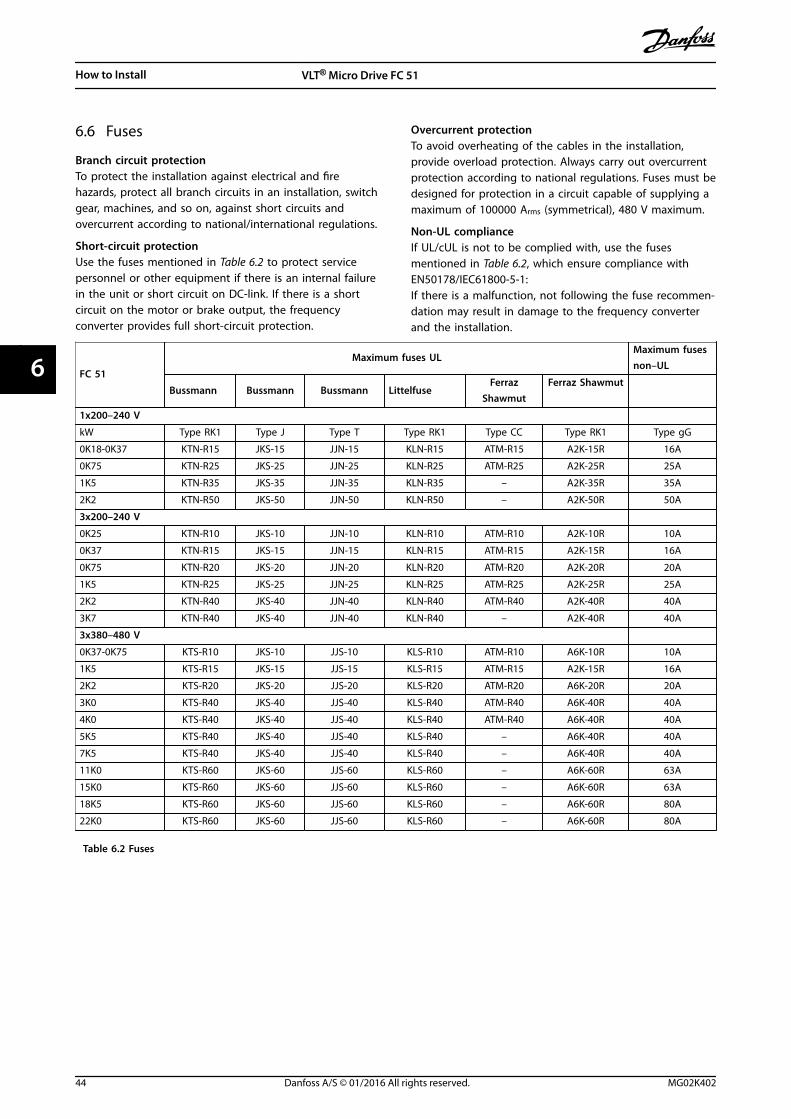
6.6 Fuses
Branch circuit protectionTo protect the installation against electrical and firehazards, protect all branch circuits in an installation, switchgear, machines, and so on, against short circuits andovercurrent according to national/international regulations.
Short-circuit protectionUse the fuses mentioned in Table 6.2 to protect servicepersonnel or other equipment if there is an internal failurein the unit or short circuit on DC-link. If there is a shortcircuit on the motor or brake output, the frequencyconverter provides full short-circuit protection.
Overcurrent protectionTo avoid overheating of the cables in the installation,provide overload protection. Always carry out overcurrentprotection according to national regulations. Fuses must bedesigned for protection in a circuit capable of supplying amaximum of 100000 Arms (symmetrical), 480 V maximum.
Non-UL complianceIf UL/cUL is not to be complied with, use the fusesmentioned in Table 6.2, which ensure compliance withEN50178/IEC61800-5-1:If there is a malfunction, not following the fuse recommen-dation may result in damage to the frequency converterand the installation.
FC 51
Maximum fuses ULMaximum fusesnon–UL
Bussmann Bussmann Bussmann LittelfuseFerraz
ShawmutFerraz Shawmut
1x200–240 V
kW Type RK1 Type J Type T Type RK1 Type CC Type RK1 Type gG
0K18-0K37 KTN-R15 JKS-15 JJN-15 KLN-R15 ATM-R15 A2K-15R 16A
0K75 KTN-R25 JKS-25 JJN-25 KLN-R25 ATM-R25 A2K-25R 25A
1K5 KTN-R35 JKS-35 JJN-35 KLN-R35 – A2K-35R 35A
2K2 KTN-R50 JKS-50 JJN-50 KLN-R50 – A2K-50R 50A
3x200–240 V
0K25 KTN-R10 JKS-10 JJN-10 KLN-R10 ATM-R10 A2K-10R 10A
0K37 KTN-R15 JKS-15 JJN-15 KLN-R15 ATM-R15 A2K-15R 16A
0K75 KTN-R20 JKS-20 JJN-20 KLN-R20 ATM-R20 A2K-20R 20A
1K5 KTN-R25 JKS-25 JJN-25 KLN-R25 ATM-R25 A2K-25R 25A
2K2 KTN-R40 JKS-40 JJN-40 KLN-R40 ATM-R40 A2K-40R 40A
3K7 KTN-R40 JKS-40 JJN-40 KLN-R40 – A2K-40R 40A
3x380–480 V
0K37-0K75 KTS-R10 JKS-10 JJS-10 KLS-R10 ATM-R10 A6K-10R 10A
1K5 KTS-R15 JKS-15 JJS-15 KLS-R15 ATM-R15 A2K-15R 16A
2K2 KTS-R20 JKS-20 JJS-20 KLS-R20 ATM-R20 A6K-20R 20A
3K0 KTS-R40 JKS-40 JJS-40 KLS-R40 ATM-R40 A6K-40R 40A
4K0 KTS-R40 JKS-40 JJS-40 KLS-R40 ATM-R40 A6K-40R 40A
5K5 KTS-R40 JKS-40 JJS-40 KLS-R40 – A6K-40R 40A
7K5 KTS-R40 JKS-40 JJS-40 KLS-R40 – A6K-40R 40A
11K0 KTS-R60 JKS-60 JJS-60 KLS-R60 – A6K-60R 63A
15K0 KTS-R60 JKS-60 JJS-60 KLS-R60 – A6K-60R 63A
18K5 KTS-R60 JKS-60 JJS-60 KLS-R60 – A6K-60R 80A
22K0 KTS-R60 JKS-60 JJS-60 KLS-R60 – A6K-60R 80A
Table 6.2 Fuses
How to Install VLT® Micro Drive FC 51
44 Danfoss A/S © 01/2016 All rights reserved. MG02K402
66
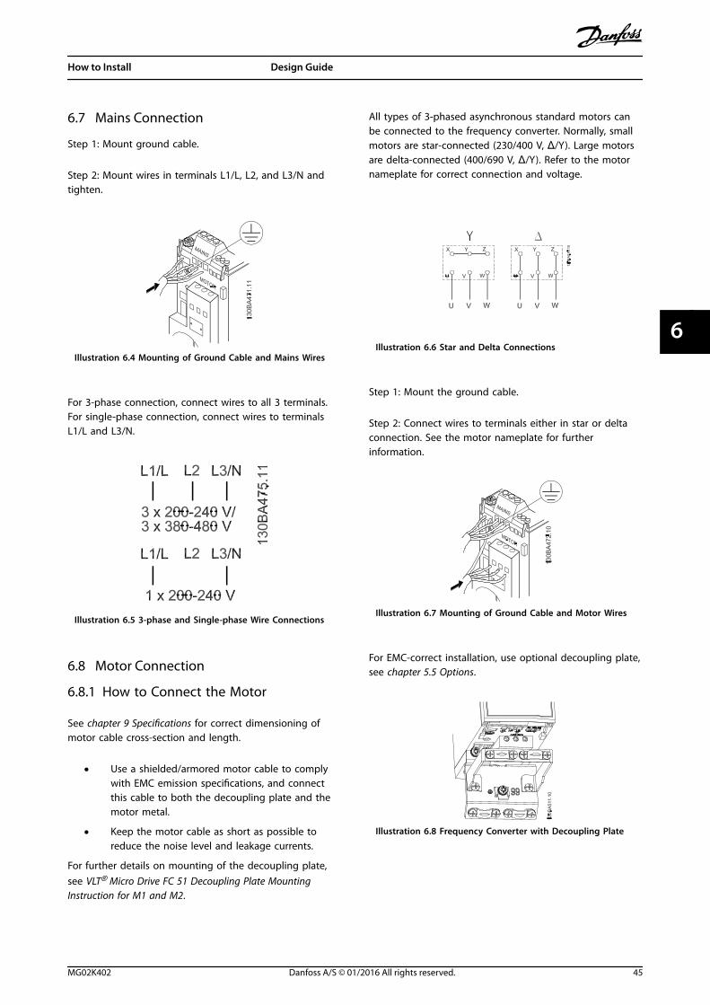
6.7 Mains Connection
Step 1: Mount ground cable.
Step 2: Mount wires in terminals L1/L, L2, and L3/N andtighten.
Illustration 6.4 Mounting of Ground Cable and Mains Wires
For 3-phase connection, connect wires to all 3 terminals.For single-phase connection, connect wires to terminalsL1/L and L3/N.
Illustration 6.5 3-phase and Single-phase Wire Connections
6.8 Motor Connection
6.8.1 How to Connect the Motor
See chapter 9 Specifications for correct dimensioning ofmotor cable cross-section and length.
• Use a shielded/armored motor cable to complywith EMC emission specifications, and connectthis cable to both the decoupling plate and themotor metal.
• Keep the motor cable as short as possible toreduce the noise level and leakage currents.
For further details on mounting of the decoupling plate,see VLT® Micro Drive FC 51 Decoupling Plate MountingInstruction for M1 and M2.
All types of 3-phased asynchronous standard motors canbe connected to the frequency converter. Normally, smallmotors are star-connected (230/400 V, Δ/Y). Large motorsare delta-connected (400/690 V, Δ/Y). Refer to the motornameplate for correct connection and voltage.
Illustration 6.6 Star and Delta Connections
Step 1: Mount the ground cable.
Step 2: Connect wires to terminals either in star or deltaconnection. See the motor nameplate for furtherinformation.
Illustration 6.7 Mounting of Ground Cable and Motor Wires
For EMC-correct installation, use optional decoupling plate,see chapter 5.5 Options.
Illustration 6.8 Frequency Converter with Decoupling Plate
How to Install Design Guide
MG02K402 Danfoss A/S © 01/2016 All rights reserved. 45
6 6
6.8.2 Motor Cables
See chapter 9 Specifications for maximum dimensioning ofmotor cable cross-section and length.
• Use a shielded/armored motor cable to complywith EMC emission specifications.
• Keep the motor cable as short as possible toreduce the noise level and leakage currents.
• Connect the motor cable shield to both thedecoupling plate of the frequency converter andto the metal cabinet of the motor.
• Make the shield connections with the largestpossible surface area (cable clamp). This is doneby using the supplied installation devices in thefrequency converter.
• Avoid mounting with twisted shield ends(pigtails), which spoils high frequency shieldingeffects.
• If it is necessary to split the shield to install amotor isolator or motor relay, the shield must becontinued with the lowest possible HFimpedance.
6.8.3 Electrical Installation of Motor Cables
Shielding of cablesAvoid installation with twisted shield ends (pigtails). Theyspoil the shielding effect at higher frequencies.If it is necessary to break the shield to install a motorisolator or motor contactor, the shield must be continuedat the lowest possible HF impedance.
Cable length and cross-sectionThe frequency converter has been tested with a givenlength of cable and a given cross-section of that cable. Ifthe cross-section is increased, the cable capacitance, andthus the leakage current, may increase, and the cablelength must be reduced correspondingly.
Switching frequencyWhen frequency converters are used together with sine-wave filters to reduce the acoustic noise from a motor, theswitching frequency must be set according to the sine-wave filter instruction in parameter 14-01 SwitchingFrequency.
Aluminum conductorsAluminum conductors are not recommended. When usingaluminum conductors, ensure that the conductor surface isclean and the oxidation is removed and sealed by aneutral acid-free grease before connecting the conductor.Retighten the terminal screw after 2 days due to thesoftness of aluminum. It is crucial to keep the connection agas-tight joint, otherwise the aluminum surface oxidizesagain.
6.8.4 EMC-correct Electrical Installation
General points to be observed to ensure EMC-correctelectrical installation.
• Use only shielded/armored motor cables andshielded/armored control cables.
• Connect the shield to ground at both ends.
• Avoid installation with twisted shield ends(pigtails), since this ruins the shielding effect athigh frequencies. Use the cable clamps providedinstead.
• It is important to ensure good electrical contactfrom the installation plate through the installationscrews to the metal cabinet of the frequencyconverter.
• Use star washers and galvanically conductiveinstallation plates.
• Do not use unshielded/unarmored motor cablesin the installation cabinets.
How to Install VLT® Micro Drive FC 51
46 Danfoss A/S © 01/2016 All rights reserved. MG02K402
66
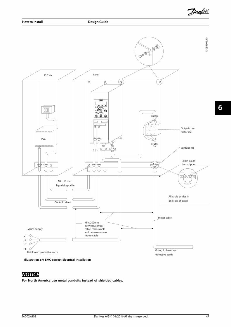
L1
L2
L3
PE
Min. 16 mm2
Equalizing cable
Control cables
All cable entries in
one side of panel
Earthing rail
Cable insula-tion stripped
Output con-tactor etc.
Motor cable
Motor, 3 phases and
PLC etc. Panel
Mains-supply
Min. 200mmbetween control cable, mains cable and between mains motor cable
PLC
Protective earthReinforced protective earth
130B
B965
.10
Illustration 6.9 EMC-correct Electrical Installation
NOTICEFor North America use metal conduits instead of shielded cables.
How to Install Design Guide
MG02K402 Danfoss A/S © 01/2016 All rights reserved. 47
6 6
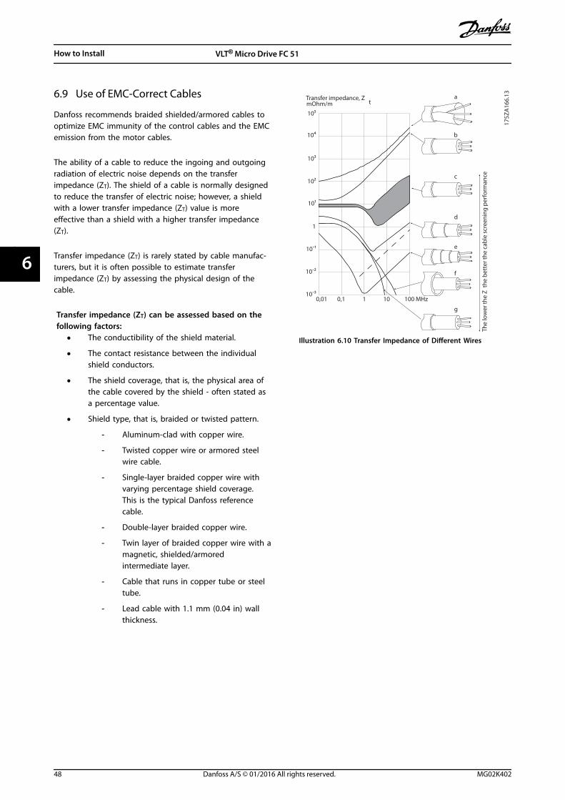
6.9 Use of EMC-Correct Cables
Danfoss recommends braided shielded/armored cables tooptimize EMC immunity of the control cables and the EMCemission from the motor cables.
The ability of a cable to reduce the ingoing and outgoingradiation of electric noise depends on the transferimpedance (ZT). The shield of a cable is normally designedto reduce the transfer of electric noise; however, a shieldwith a lower transfer impedance (ZT) value is moreeffective than a shield with a higher transfer impedance(ZT).
Transfer impedance (ZT) is rarely stated by cable manufac-turers, but it is often possible to estimate transferimpedance (ZT) by assessing the physical design of thecable.
Transfer impedance (ZT) can be assessed based on thefollowing factors:
• The conductibility of the shield material.
• The contact resistance between the individualshield conductors.
• The shield coverage, that is, the physical area ofthe cable covered by the shield - often stated asa percentage value.
• Shield type, that is, braided or twisted pattern.
- Aluminum-clad with copper wire.
- Twisted copper wire or armored steelwire cable.
- Single-layer braided copper wire withvarying percentage shield coverage.This is the typical Danfoss referencecable.
- Double-layer braided copper wire.
- Twin layer of braided copper wire with amagnetic, shielded/armoredintermediate layer.
- Cable that runs in copper tube or steeltube.
- Lead cable with 1.1 mm (0.04 in) wallthickness.
175Z
A16
6.13
0,01 0,1 1 10 100 MHz
10ˉ2
10ˉ3
10ˉ1
1
101
102
104
103
105
a
b
c
d
e
f
g
The
low
er th
e Z
the
bett
er th
e ca
ble
scre
enin
g pe
rfor
man
ce
Transfer impedance, ZtmOhm/m
Illustration 6.10 Transfer Impedance of Different Wires
How to Install VLT® Micro Drive FC 51
48 Danfoss A/S © 01/2016 All rights reserved. MG02K402
66
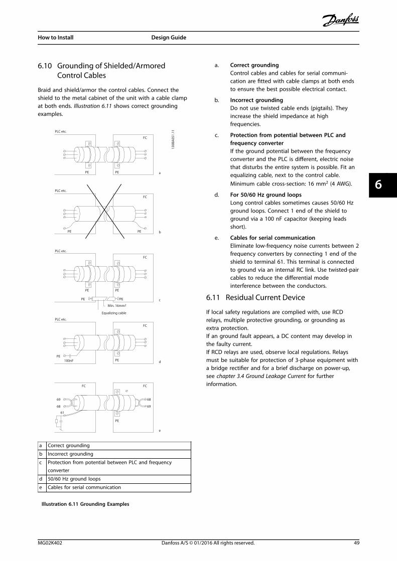
6.10 Grounding of Shielded/ArmoredControl Cables
Braid and shield/armor the control cables. Connect theshield to the metal cabinet of the unit with a cable clampat both ends. Illustration 6.11 shows correct groundingexamples.
PE
FC
PE13
0BA
051.
11
PE PE
FC
PE PE
FC
100nF PE
FC
69
FC
PE PE
PE
68
61
68
69
FC
PE
a
b
c
d
e
PLC etc.
PLC etc.
PLC etc.
PLC etc.
Equalizing cable
Min. 16mm2
a Correct grounding
b Incorrect grounding
c Protection from potential between PLC and frequencyconverter
d 50/60 Hz ground loops
e Cables for serial communication
Illustration 6.11 Grounding Examples
a. Correct groundingControl cables and cables for serial communi-cation are fitted with cable clamps at both endsto ensure the best possible electrical contact.
b. Incorrect groundingDo not use twisted cable ends (pigtails). Theyincrease the shield impedance at highfrequencies.
c. Protection from potential between PLC andfrequency converterIf the ground potential between the frequencyconverter and the PLC is different, electric noisethat disturbs the entire system is possible. Fit anequalizing cable, next to the control cable.Minimum cable cross-section: 16 mm2 (4 AWG).
d. For 50/60 Hz ground loopsLong control cables sometimes causes 50/60 Hzground loops. Connect 1 end of the shield toground via a 100 nF capacitor (keeping leadsshort).
e. Cables for serial communicationEliminate low-frequency noise currents between 2frequency converters by connecting 1 end of theshield to terminal 61. This terminal is connectedto ground via an internal RC link. Use twisted-paircables to reduce the differential modeinterference between the conductors.
6.11 Residual Current Device
If local safety regulations are complied with, use RCDrelays, multiple protective grounding, or grounding asextra protection.If an ground fault appears, a DC content may develop inthe faulty current.If RCD relays are used, observe local regulations. Relaysmust be suitable for protection of 3-phase equipment witha bridge rectifier and for a brief discharge on power-up,see chapter 3.4 Ground Leakage Current for furtherinformation.
How to Install Design Guide
MG02K402 Danfoss A/S © 01/2016 All rights reserved. 49
6 6
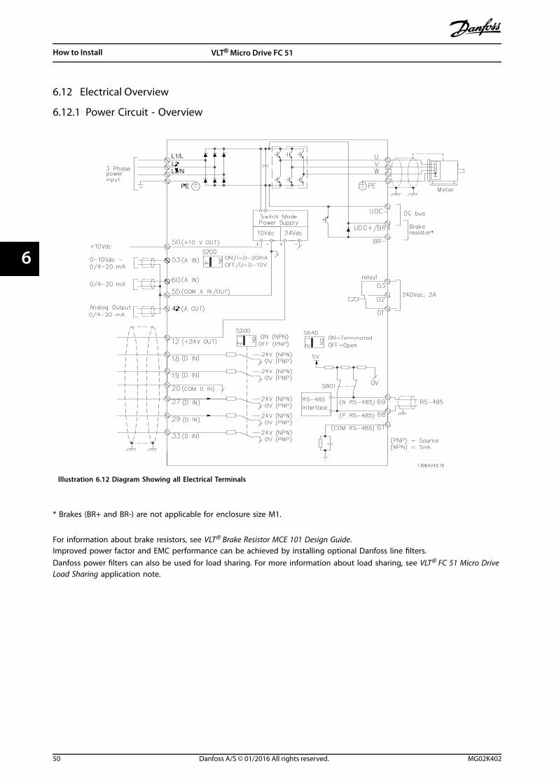
6.12 Electrical Overview
6.12.1 Power Circuit - Overview
Illustration 6.12 Diagram Showing all Electrical Terminals
* Brakes (BR+ and BR-) are not applicable for enclosure size M1.
For information about brake resistors, see VLT® Brake Resistor MCE 101 Design Guide.Improved power factor and EMC performance can be achieved by installing optional Danfoss line filters.Danfoss power filters can also be used for load sharing. For more information about load sharing, see VLT® FC 51 Micro DriveLoad Sharing application note.
How to Install VLT® Micro Drive FC 51
50 Danfoss A/S © 01/2016 All rights reserved. MG02K402
66
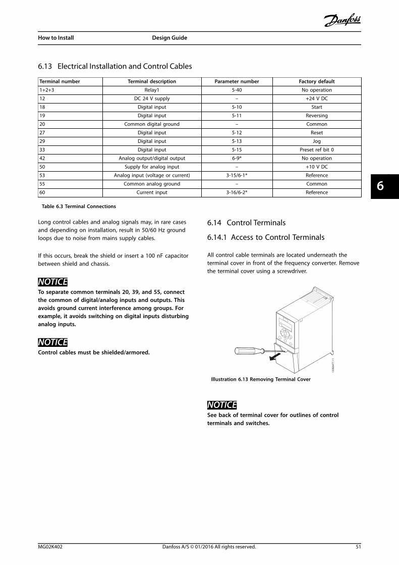
6.13 Electrical Installation and Control Cables
Terminal number Terminal description Parameter number Factory default
1+2+3 Relay1 5-40 No operation
12 DC 24 V supply – +24 V DC
18 Digital input 5-10 Start
19 Digital input 5-11 Reversing
20 Common digital ground – Common
27 Digital input 5-12 Reset
29 Digital input 5-13 Jog
33 Digital input 5-15 Preset ref bit 0
42 Analog output/digital output 6-9* No operation
50 Supply for analog input – +10 V DC
53 Analog input (voltage or current) 3-15/6-1* Reference
55 Common analog ground – Common
60 Current input 3-16/6-2* Reference
Table 6.3 Terminal Connections
Long control cables and analog signals may, in rare casesand depending on installation, result in 50/60 Hz groundloops due to noise from mains supply cables.
If this occurs, break the shield or insert a 100 nF capacitorbetween shield and chassis.
NOTICETo separate common terminals 20, 39, and 55, connectthe common of digital/analog inputs and outputs. Thisavoids ground current interference among groups. Forexample, it avoids switching on digital inputs disturbinganalog inputs.
NOTICEControl cables must be shielded/armored.
6.14 Control Terminals
6.14.1 Access to Control Terminals
All control cable terminals are located underneath theterminal cover in front of the frequency converter. Removethe terminal cover using a screwdriver.
Illustration 6.13 Removing Terminal Cover
NOTICESee back of terminal cover for outlines of controlterminals and switches.
How to Install Design Guide
MG02K402 Danfoss A/S © 01/2016 All rights reserved. 51
6 6
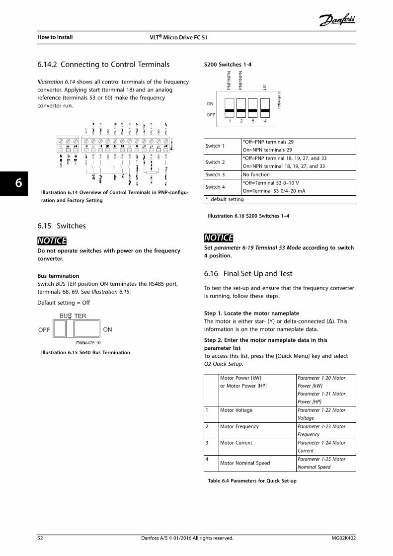
6.14.2 Connecting to Control Terminals
Illustration 6.14 shows all control terminals of the frequencyconverter. Applying start (terminal 18) and an analogreference (terminals 53 or 60) make the frequencyconverter run.
Illustration 6.14 Overview of Control Terminals in PNP-configu-ration and Factory Setting
6.15 Switches
NOTICEDo not operate switches with power on the frequencyconverter.
Bus terminationSwitch BUS TER position ON terminates the RS485 port,terminals 68, 69. See Illustration 6.15.
Default setting = Off
Illustration 6.15 S640 Bus Termination
S200 Switches 1-4
Switch 1*Off=PNP terminals 29On=NPN terminals 29
Switch 2*Off=PNP terminal 18, 19, 27, and 33On=NPN terminal 18, 19, 27, and 33
Switch 3 No function
Switch 4*Off=Terminal 53 0–10 VOn=Terminal 53 0/4–20 mA
*=default setting
Illustration 6.16 S200 Switches 1–4
NOTICESet parameter 6-19 Terminal 53 Mode according to switch4 position.
6.16 Final Set-Up and Test
To test the set-up and ensure that the frequency converteris running, follow these steps.
Step 1. Locate the motor nameplateThe motor is either star- (Y) or delta-connected (Δ). Thisinformation is on the motor nameplate data.
Step 2. Enter the motor nameplate data in thisparameter listTo access this list, press the [Quick Menu] key and selectQ2 Quick Setup.
Motor Power [kW]or Motor Power [HP]
Parameter 1-20 MotorPower [kW]Parameter 1-21 MotorPower [HP]
1 Motor Voltage Parameter 1-22 MotorVoltage
2 Motor Frequency Parameter 1-23 MotorFrequency
3 Motor Current Parameter 1-24 MotorCurrent
4Motor Nominal Speed
Parameter 1-25 MotorNominal Speed
Table 6.4 Parameters for Quick Set-up
How to Install VLT® Micro Drive FC 51
52 Danfoss A/S © 01/2016 All rights reserved. MG02K402
66
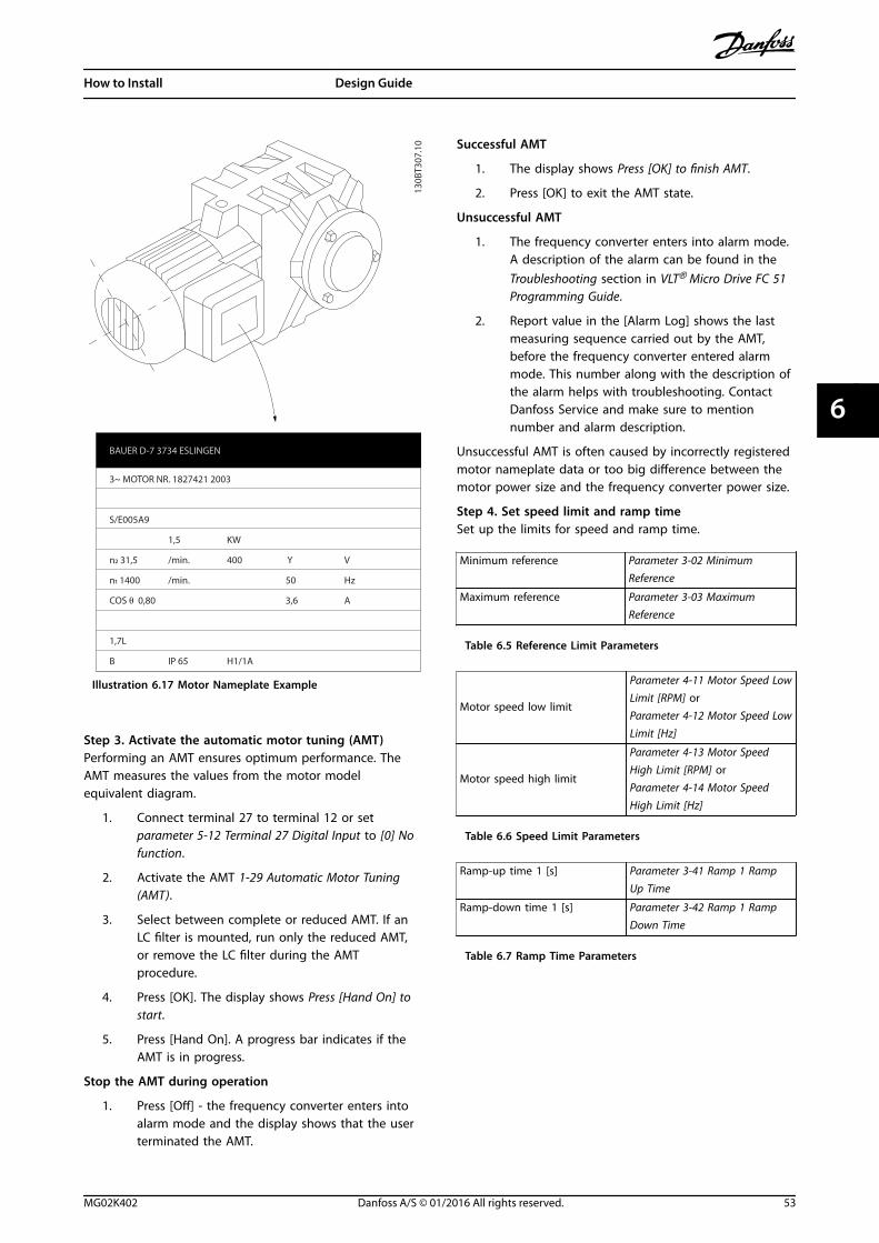
3~ MOTOR NR. 1827421 2003
S/E005A9
1,5 KW
n2 31,5 /min. 400 Y V
n1 1400 /min. 50 Hz
COS 0,80 3,6 A
1,7L
B IP 65 H1/1A
BAUER D-7 3734 ESLINGEN
130B
T307
.10
Illustration 6.17 Motor Nameplate Example
Step 3. Activate the automatic motor tuning (AMT)Performing an AMT ensures optimum performance. TheAMT measures the values from the motor modelequivalent diagram.
1. Connect terminal 27 to terminal 12 or setparameter 5-12 Terminal 27 Digital Input to [0] Nofunction.
2. Activate the AMT 1-29 Automatic Motor Tuning(AMT).
3. Select between complete or reduced AMT. If anLC filter is mounted, run only the reduced AMT,or remove the LC filter during the AMTprocedure.
4. Press [OK]. The display shows Press [Hand On] tostart.
5. Press [Hand On]. A progress bar indicates if theAMT is in progress.
Stop the AMT during operation
1. Press [Off] - the frequency converter enters intoalarm mode and the display shows that the userterminated the AMT.
Successful AMT
1. The display shows Press [OK] to finish AMT.
2. Press [OK] to exit the AMT state.
Unsuccessful AMT
1. The frequency converter enters into alarm mode.A description of the alarm can be found in theTroubleshooting section in VLT® Micro Drive FC 51Programming Guide.
2. Report value in the [Alarm Log] shows the lastmeasuring sequence carried out by the AMT,before the frequency converter entered alarmmode. This number along with the description ofthe alarm helps with troubleshooting. ContactDanfoss Service and make sure to mentionnumber and alarm description.
Unsuccessful AMT is often caused by incorrectly registeredmotor nameplate data or too big difference between themotor power size and the frequency converter power size.
Step 4. Set speed limit and ramp timeSet up the limits for speed and ramp time.
Minimum reference Parameter 3-02 MinimumReference
Maximum reference Parameter 3-03 MaximumReference
Table 6.5 Reference Limit Parameters
Motor speed low limit
Parameter 4-11 Motor Speed LowLimit [RPM] orParameter 4-12 Motor Speed LowLimit [Hz]
Motor speed high limit
Parameter 4-13 Motor SpeedHigh Limit [RPM] orParameter 4-14 Motor SpeedHigh Limit [Hz]
Table 6.6 Speed Limit Parameters
Ramp-up time 1 [s] Parameter 3-41 Ramp 1 RampUp Time
Ramp-down time 1 [s] Parameter 3-42 Ramp 1 RampDown Time
Table 6.7 Ramp Time Parameters
How to Install Design Guide
MG02K402 Danfoss A/S © 01/2016 All rights reserved. 53
6 6
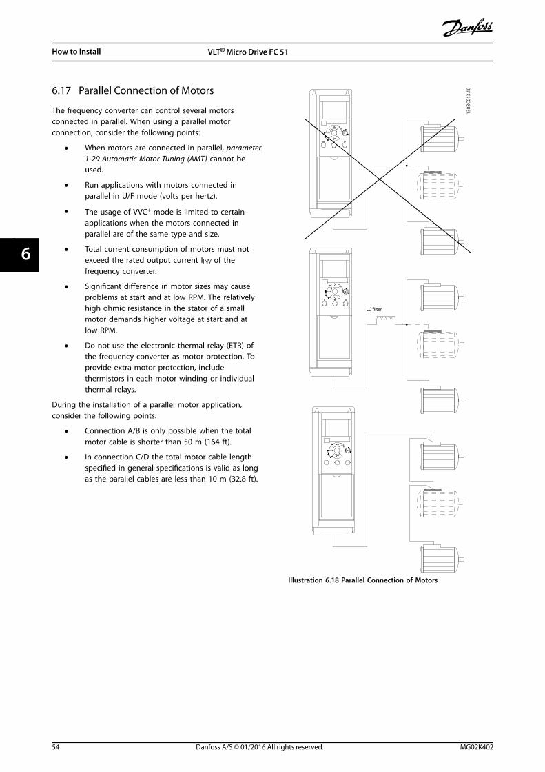
6.17 Parallel Connection of Motors
The frequency converter can control several motorsconnected in parallel. When using a parallel motorconnection, consider the following points:
• When motors are connected in parallel, parameter1-29 Automatic Motor Tuning (AMT) cannot beused.
• Run applications with motors connected inparallel in U/F mode (volts per hertz).
• The usage of VVC+ mode is limited to certainapplications when the motors connected inparallel are of the same type and size.
• Total current consumption of motors must notexceed the rated output current IINV of thefrequency converter.
• Significant difference in motor sizes may causeproblems at start and at low RPM. The relativelyhigh ohmic resistance in the stator of a smallmotor demands higher voltage at start and atlow RPM.
• Do not use the electronic thermal relay (ETR) ofthe frequency converter as motor protection. Toprovide extra motor protection, includethermistors in each motor winding or individualthermal relays.
During the installation of a parallel motor application,consider the following points:
• Connection A/B is only possible when the totalmotor cable is shorter than 50 m (164 ft).
• In connection C/D the total motor cable lengthspecified in general specifications is valid as longas the parallel cables are less than 10 m (32.8 ft).
LC filter
130B
C01
3.10
Illustration 6.18 Parallel Connection of Motors
How to Install VLT® Micro Drive FC 51
54 Danfoss A/S © 01/2016 All rights reserved. MG02K402
66
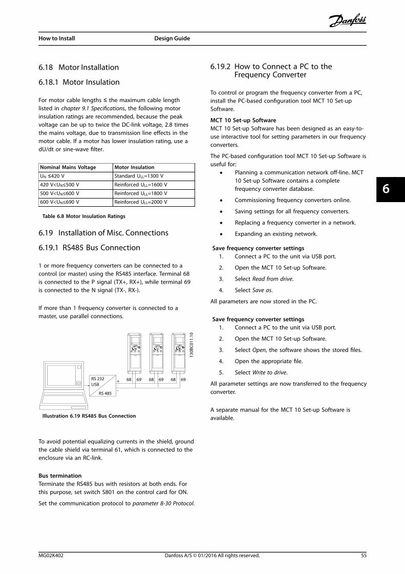
6.18 Motor Installation
6.18.1 Motor Insulation
For motor cable lengths ≤ the maximum cable lengthlisted in chapter 9.1 Specifications, the following motorinsulation ratings are recommended, because the peakvoltage can be up to twice the DC-link voltage, 2.8 timesthe mains voltage, due to transmission line effects in themotor cable. If a motor has lower insulation rating, use adU/dt or sine-wave filter.
Nominal Mains Voltage Motor Insulation
UN ≤420 V Standard ULL=1300 V
420 V<UN≤500 V Reinforced ULL=1600 V
500 V<UN≤600 V Reinforced ULL=1800 V
600 V<UN≤690 V Reinforced ULL=2000 V
Table 6.8 Motor Insulation Ratings
6.19 Installation of Misc. Connections
6.19.1 RS485 Bus Connection
1 or more frequency converters can be connected to acontrol (or master) using the RS485 interface. Terminal 68is connected to the P signal (TX+, RX+), while terminal 69is connected to the N signal (TX-, RX-).
If more than 1 frequency converter is connected to amaster, use parallel connections.
130B
C01
1.10
68 69 68 69 68 69
RS 485
RS 232USB
+
-
Illustration 6.19 RS485 Bus Connection
To avoid potential equalizing currents in the shield, groundthe cable shield via terminal 61, which is connected to theenclosure via an RC-link.
Bus terminationTerminate the RS485 bus with resistors at both ends. Forthis purpose, set switch S801 on the control card for ON.
Set the communication protocol to parameter 8-30 Protocol.
6.19.2 How to Connect a PC to theFrequency Converter
To control or program the frequency converter from a PC,install the PC-based configuration tool MCT 10 Set-upSoftware.
MCT 10 Set-up SoftwareMCT 10 Set-up Software has been designed as an easy-to-use interactive tool for setting parameters in our frequencyconverters.
The PC-based configuration tool MCT 10 Set-up Software isuseful for:
• Planning a communication network off-line. MCT10 Set-up Software contains a completefrequency converter database.
• Commissioning frequency converters online.
• Saving settings for all frequency converters.
• Replacing a frequency converter in a network.
• Expanding an existing network.
Save frequency converter settings1. Connect a PC to the unit via USB port.
2. Open the MCT 10 Set-up Software.
3. Select Read from drive.
4. Select Save as.
All parameters are now stored in the PC.
Save frequency converter settings1. Connect a PC to the unit via USB port.
2. Open the MCT 10 Set-up Software.
3. Select Open, the software shows the stored files.
4. Open the appropriate file.
5. Select Write to drive.
All parameter settings are now transferred to the frequencyconverter.
A separate manual for the MCT 10 Set-up Software isavailable.
How to Install Design Guide
MG02K402 Danfoss A/S © 01/2016 All rights reserved. 55
6 6
The MCT 10 Set-up Software modulesThe following modules are included in the softwarepackage:
MCT 10 Set-up SoftwareSetting parameters.Copy to and from frequency converters.Documentation and print out of parametersettings including diagrams.
External user interfacePreventive maintenance schedule.Clock settings.Timed action programming.Smart logic controller set-up.
Table 6.9 MCT 10 Set-up Software
Ordering numberOrder the CD containing the MCT 10 Set-up Softwareusing code number 130B1000.
MCT 10 Set-up Software can also be downloaded from theDanfoss Internet: www.danfoss.com/BusinessAreas/DrivesSo-lutions/Softwaredownload/DDPC+Software+Program.htm.
6.20 Safety
6.20.1 High-voltage Test
Carry out a high-voltage test by short-circuiting terminalsU, V, W, L1, L2, and L3. Energize maximum 2.15 kV DC for380–500 V frequency converters and 2.525 kV DC for 525–690 V frequency converters for 1 s between this shortcircuit and the chassis.
WARNINGLEAKAGE CURRENT HAZARDLeakage currents exceed 3.5 mA. Failure to ground thefrequency converter properly can result in death orserious injury.
• Ensure the correct grounding of the equipmentby a certified electrical installer.
6.20.2 Safety Ground Connection
The frequency converter has a high leakage current andmust be grounded appropriately for safety reasonsaccording to EN 50178.
WARNINGLEAKAGE CURRENT HAZARDLeakage currents exceed 3.5 mA. Failure to ground thefrequency converter properly can result in death orserious injury.
• Ensure the correct grounding of the equipmentby a certified electrical installer.
How to Install VLT® Micro Drive FC 51
56 Danfoss A/S © 01/2016 All rights reserved. MG02K402
66
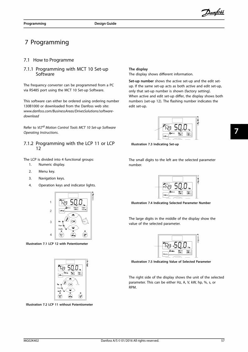
7 Programming
7.1 How to Programme
7.1.1 Programming with MCT 10 Set-upSoftware
The frequency converter can be programmed from a PCvia RS485 port using the MCT 10 Set-up Software.
This software can either be ordered using ordering number130B1000 or downloaded from the Danfoss web site:www.danfoss.com/BusinessAreas/DrivesSolutions/software-download
Refer to VLT® Motion Control Tools MCT 10 Set-up SoftwareOperating Instructions.
7.1.2 Programming with the LCP 11 or LCP12
The LCP is divided into 4 functional groups:1. Numeric display.
2. Menu key.
3. Navigation keys.
4. Operation keys and indicator lights.
Illustration 7.1 LCP 12 with Potentiometer
Illustration 7.2 LCP 11 without Potentiometer
The displayThe display shows different information.
Set-up number shows the active set-up and the edit set-up. If the same set-up acts as both active and edit set-up,only that set-up number is shown (factory setting).When active and edit set-up differ, the display shows bothnumbers (set-up 12). The flashing number indicates theedit set-up.
Illustration 7.3 Indicating Set-up
The small digits to the left are the selected parameternumber.
Illustration 7.4 Indicating Selected Parameter Number
The large digits in the middle of the display show thevalue of the selected parameter.
Illustration 7.5 Indicating Value of Selected Parameter
The right side of the display shows the unit of the selectedparameter. This can be either Hz, A, V, kW, hp, %, s, orRPM.
Programming Design Guide
MG02K402 Danfoss A/S © 01/2016 All rights reserved. 57
7 7
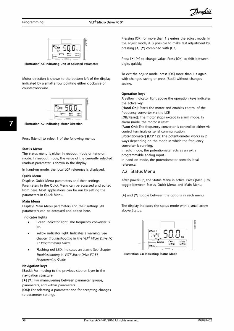
Illustration 7.6 Indicating Unit of Selected Parameter
Motor direction is shown to the bottom left of the display,indicated by a small arrow pointing either clockwise orcounterclockwise.
Illustration 7.7 Indicating Motor Direction
Press [Menu] to select 1 of the following menus
Status MenuThe status menu is either in readout mode or hand-onmode. In readout mode, the value of the currently selectedreadout parameter is shown in the display.
In hand-on mode, the local LCP reference is displayed.
Quick MenuDisplays Quick Menu parameters and their settings.Parameters in the Quick Menu can be accessed and editedfrom here. Most applications can be run by setting theparameters in Quick Menu.
Main MenuDisplays Main Menu parameters and their settings. Allparameters can be accessed and edited here.
Indicator lights• Green indicator light: The frequency converter is
on.
• Yellow indicator light: Indicates a warning. Seechapter Troubleshooting in the VLT® Micro Drive FC51 Programming Guide.
• Flashing red LED: Indicates an alarm. See chapterTroubleshooting in VLT® Micro Drive FC 51Programming Guide.
Navigation keys[Back]: For moving to the previous step or layer in thenavigation structure.[▲] [▼]: For maneuvering between parameter groups,parameters, and within parameters.[OK]: For selecting a parameter and for accepting changesto parameter settings.
Pressing [OK] for more than 1 s enters the adjust mode. Inthe adjust mode, it is possible to make fast adjustment bypressing [▲] [▼] combined with [OK].
Press [▲] [▼] to change value. Press [OK] to shift betweendigits quickly.
To exit the adjust mode, press [OK] more than 1 s againwith changes saving or press [Back] without changessaving.
Operation keysA yellow indicator light above the operation keys indicatesthe active key.[Hand On]: Starts the motor and enables control of thefrequency converter via the LCP.[Off/Reset]: The motor stops except in alarm mode. Inalarm mode, the motor is reset.[Auto On]: The frequency converter is controlled either viacontrol terminals or serial communication.[Potentiometer] (LCP 12): The potentiometer works in 2ways depending on the mode in which the frequencyconverter is running.In auto mode, the potentiometer acts as an extraprogrammable analog input.In hand-on mode, the potentiometer controls localreference.
7.2 Status Menu
After power-up, the Status Menu is active. Press [Menu] totoggle between Status, Quick Menu, and Main Menu.
[▲] and [▼] toggle between the options in each menu.
The display indicates the status mode with a small arrowabove Status.
130B
A46
6.10
Illustration 7.8 Indicating Status Mode
Programming VLT® Micro Drive FC 51
58 Danfoss A/S © 01/2016 All rights reserved. MG02K402
77
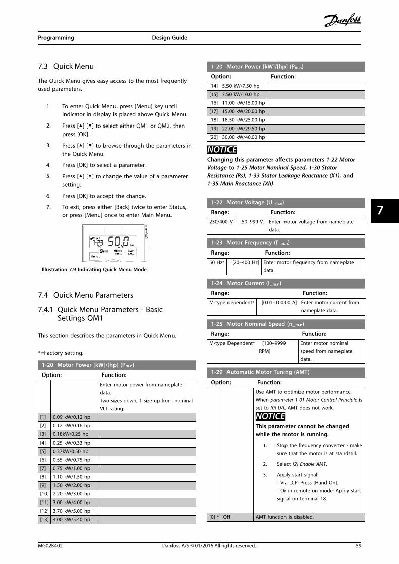
7.3 Quick Menu
The Quick Menu gives easy access to the most frequentlyused parameters.
1. To enter Quick Menu, press [Menu] key untilindicator in display is placed above Quick Menu.
2. Press [▲] [▼] to select either QM1 or QM2, thenpress [OK].
3. Press [▲] [▼] to browse through the parameters inthe Quick Menu.
4. Press [OK] to select a parameter.
5. Press [▲] [▼] to change the value of a parametersetting.
6. Press [OK] to accept the change.
7. To exit, press either [Back] twice to enter Status,or press [Menu] once to enter Main Menu.
Illustration 7.9 Indicating Quick Menu Mode
7.4 Quick Menu Parameters
7.4.1 Quick Menu Parameters - BasicSettings QM1
This section describes the parameters in Quick Menu.
*=Factory setting.
1-20 Motor Power [kW]/[hp] (Pm.n)
Option: Function:
Enter motor power from nameplatedata.Two sizes down, 1 size up from nominalVLT rating.
[1] 0.09 kW/0.12 hp
[2] 0.12 kW/0.16 hp
[3] 0.18kW/0.25 hp
[4] 0.25 kW/0.33 hp
[5] 0.37kW/0.50 hp
[6] 0.55 kW/0.75 hp
[7] 0.75 kW/1.00 hp
[8] 1.10 kW/1.50 hp
[9] 1.50 kW/2.00 hp
[10] 2.20 kW/3.00 hp
[11] 3.00 kW/4.00 hp
[12] 3.70 kW/5.00 hp
[13] 4.00 kW/5.40 hp
1-20 Motor Power [kW]/[hp] (Pm.n)
Option: Function:
[14] 5.50 kW/7.50 hp
[15] 7.50 kW/10.0 hp
[16] 11.00 kW/15.00 hp
[17] 15.00 kW/20.00 hp
[18] 18.50 kW/25.00 hp
[19] 22.00 kW/29.50 hp
[20] 30.00 kW/40.00 hp
NOTICEChanging this parameter affects parameters 1-22 MotorVoltage to 1-25 Motor Nominal Speed, 1-30 StatorResistance (Rs), 1-33 Stator Leakage Reactance (X1), and1-35 Main Reactance (Xh).
1-22 Motor Voltage (U_m.n)
Range: Function:
230/400 V [50–999 V] Enter motor voltage from nameplatedata.
1-23 Motor Frequency (f_m.n)
Range: Function:
50 Hz* [20–400 Hz] Enter motor frequency from nameplatedata.
1-24 Motor Current (I_m.n)
Range: Function:
M-type dependent* [0.01–100.00 A] Enter motor current fromnameplate data.
1-25 Motor Nominal Speed (n_m.n)
Range: Function:
M-type Dependent* [100–9999RPM]
Enter motor nominalspeed from nameplatedata.
1-29 Automatic Motor Tuning (AMT)
Option: Function:
Use AMT to optimize motor performance.When parameter 1-01 Motor Control Principle isset to [0] U/f, AMT does not work.
NOTICEThis parameter cannot be changedwhile the motor is running.
1. Stop the frequency converter - makesure that the motor is at standstill.
2. Select [2] Enable AMT.
3. Apply start signal:- Via LCP: Press [Hand On].- Or in remote on mode: Apply startsignal on terminal 18.
[0] * Off AMT function is disabled.
Programming Design Guide
MG02K402 Danfoss A/S © 01/2016 All rights reserved. 59
7 7
1-29 Automatic Motor Tuning (AMT)
Option: Function:
[2] Enable AMT AMT function starts running.
NOTICETo gain optimum tuning of thefrequency converter, run AMT on a coldmotor.
[3] CompleteAMT withRotatingmotor
NOTICEThe motor rotates when this option isactive.
With this option selected, the frequencyconverter optimizes the following parameters:1-35 Main Reactance (X2), 1-30 StatorResistance (Rs), and 1-33 Stator LeakageReactance (X1).
3-02 Minimum Reference
Range: Function:
0.00* [-4999-4999] Enter the value for minimum reference.The sum of all internal and externalreferences are clamped (limited) to theminimum reference value, parameter 3-02Minimum Reference.
3-03 Maximum Reference
Range: Function:
The range of this parameter isparameter 3-02 MinimumReference–4999.
60.000 Hz or50.000 Hzdepending on thesetting in par.0-03.*
[-4999–4999]
Enter the value for maximumreference.The sum of all internal andexternal references are clamped(limited) to the maximumreference value, parameter 3-03Maximum Reference.
3-41 Ramp1 Ramp-up Time
Range: Function:
Sizerelated*
[0.05-3600.00s]
Enter ramp-up time from 0 Hz torated motor frequency (fM,N) set inparameter 1-23 Motor Frequency.Select a ramp-up time ensuringthat torque limit is not exceeded,see parameter 4-16 Torque Limit inMotor Mode.
3-42 Ramp1 Ramp-down Time
Range: Function:
Sizerelated*
[0.05-3600.00s]
Enter ramp-down time from ratedmotor frequency (fM,N) in parameter1-23 Motor Frequency to 0 Hz.Select a ramp-down time that doesnot cause overvoltage in the inverterdue to regenerative operation ofmotor. Furthermore, regenerativetorque must not exceed limit set inparameter 4-17 Torque Limit inGenerator Mode.
Programming VLT® Micro Drive FC 51
60 Danfoss A/S © 01/2016 All rights reserved. MG02K402
77
7.4.2 Quick Menu Parameters - PI BasicSettings QM2
The following is a brief description of the parameters forthe PI basic settings. For a more detailed description, seeVLT® Micro Drive FC 51 Programming Guide.
1-00 Configuration Mode
Option: Function:
Use this parameter for selecting theapplication control principle to be used whena remote reference is active.
NOTICEChanging this parameter resetsparameter 3-00 Reference Range,parameter 3-02 Minimum Reference andparameter 3-03 Maximum Reference totheir default values.
NOTICEThis parameter cannot be adjustedwhile motor is running.
[0 ] * SpeedOpenLoop
For normal speed control (references).
[3] Process Enables process closed-loop control. Seeparameter group 7-3* Process PI Control forfurther information on PI controller.
3-02 Minimum Reference
Range: Function:
0.00* [-4999-4999] Enter the value for minimum reference.The sum of all internal and externalreferences are clamped (limited) to theminimum reference value, parameter 3-02Minimum Reference.
3-03 Maximum Reference
Range: Function:
The range of this parameter isparameter 3-02 MinimumReference–4999.
60.000 Hz or50.000 Hzdepending on thesetting in par.0-03.*
[-4999–4999]
Enter the value for maximumreference.The sum of all internal andexternal references are clamped(limited) to the maximumreference value, parameter 3-03Maximum Reference.
3-10 Preset Reference
Option: Function:
Each parameter set-up contains 8 presetreferences which are selectable via 3 digitalinputs or fieldbus.
[18]Bit2
[17]Bit1
[16]Bit0
[16]Bit0
0 0 0 0
0 0 1 1
0 1 0 2
0 1 1 3
1 0 0 4
1 0 1 5
1 1 0 6
1 1 1 7
Table 7.1 Parameter Group 5-1* DigitalInputs Option [16], [17], and [18]
[0.00]*
-100.00–100.00%
Enter the different preset references usingarray programming.Normally, 100%=value set in parameter 3-03Maximum Reference.However, there are exceptions if parameter3-00 Reference Range is set to [0] Min - Max.Example 1:Parameter 3-02 Minimum Reference is set to 20,and parameter 3-03 Maximum Reference is setto 50. In this case 0%=0, and 100%=50.Example 2:Parameter 3-02 Minimum Reference is set to -70,and parameter 3-03 Maximum Reference is setto 50. In this case 0%=0, and 100%=70.
4-12 Motor Speed Low Limit
Range: Function:
0.0 Hz* [0.0-400.0 Hz] Set the minimum motor speed limitcorresponding to the minimum outputfrequency of the motor shaft.
NOTICEAs the minimum output frequencyis an absolute value, and thefrequency converter cannotdeviate from it.
4-14 Motor Speed High Limit
Range: Function:
65.0 Hz* [0.0-400.0 Hz] Set the maximum motor speedcorresponding to the maximum outputfrequency of the motor shaft.
NOTICEThe maximum output frequencyis an absolute value, and thefrequency converter cannotdeviate from it.
Programming Design Guide
MG02K402 Danfoss A/S © 01/2016 All rights reserved. 61
7 7
6-22 Terminal 60 Low Current
Range: Function:
NOTICESet the value to a minimum of2 mA to activate the live zerotimeout function in parameter 6-01Live Zero Timeout Time.
This reference signal should correspondto minimum reference value set inparameter 6-24 Terminal 60 Low Ref./Feedb.Value.
0.14mA*
[0.00–20.00 mA]
Enter the low current value.
6-23 Terminal 60 High Current
Range: Function:
This reference signal shouldcorrespond to the high current valueset in parameter 6-25 Terminal 60 HighRef./Feedb. Value.
20.00 mA* [0.00–20.00mA]
Enter high current value.
6-24 Terminal 60 Low Ref./Feedb. Value
Range: Function:
The scaling value corresponding to thelow current set in parameter 6-22 Terminal60 Low Current.
0.000* [-4999–4999] Enter analog input scaling value.
6-25 Terminal 60 High Ref./Feedb. Value
Range: Function:
The scaling valuecorresponding to the highcurrent set in parameter6-23 Terminal 60 HighCurrent.
60.000 Hz or 50.000Hz depending onthe setting in par.0-03.*
[-4999-4999] Enter analog input scalingvalue.
6-26 Terminal 60 Filter Time Constant
Range: Function:
A first-order digital low-pass filter timeconstant for suppressing electrical noise interminal 60. A high time constant valueimproves dampening, but also increasestime delay through the filter.
NOTICEThis parameter cannot be changedwhile the motor is running.
0.01 s* [0.01–10.00 s]
Enter the time constant.
7-20 Process CL Feedback Resources
Option: Function:
Select input to function as feedbacksignal.
[0] * No Function
[1] Analog Input 53
[2] Analog Input 60
[8] Pulse Input 33
[11] Local Bus
7-30 Process PI Normal/Inverse Control
Option: Function:
[0] * Normal Feedback larger than setpoint results in a speedreduction.Feedback less than setpoint results in a speedincrease.
[1] Inverse Feedback larger than setpoint results in a speedincrease.Feedback less than setpoint results in a speedreduction.
7-31 Process PI Anti Windup
Option: Function:
[0] Disable Regulation of a given error continues even whenthe output frequency cannot be increased/decreased.
[1] * Enable PI controller ceases from regulating a given errorwhen the output frequency cannot be increased/decreased.
7-32 Process PI Start Speed
Range: Function:
0.0 Hz* [0.0–200.0 Hz] Until the set motor speed has beenreached, the frequency converteroperates in open-loop mode.
7-33 Process PI Proportional Gain
Option: Function:
[0.01] * 0.00–10.00 Enter the value for the proportional gain,that is, the multiplication factor of the errorbetween the setpoint and the feedbacksignal.
NOTICE0.00=Off.
7-34 Process PI Integral Time
Range: Function:
9999.00 s* [0.10–9999.00 s]
The integrator provides an increasinggain at a constant error between thesetpoint and the feedback signal. Theintegral time is the time needed by theintegrator to reach the same gain asthe proportional gain.
Programming VLT® Micro Drive FC 51
62 Danfoss A/S © 01/2016 All rights reserved. MG02K402
77
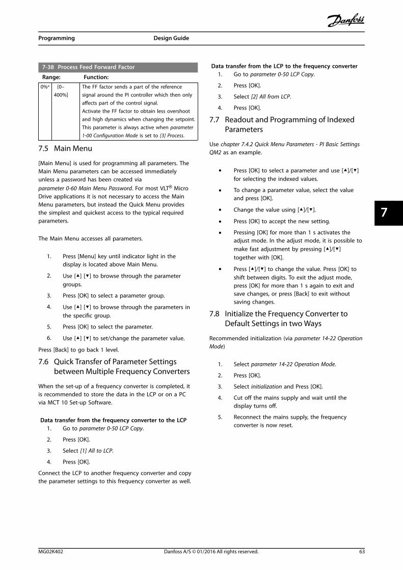
7-38 Process Feed Forward Factor
Range: Function:
0%* [0–400%]
The FF factor sends a part of the referencesignal around the PI controller which then onlyaffects part of the control signal.Activate the FF factor to obtain less overshootand high dynamics when changing the setpoint.This parameter is always active when parameter1-00 Configuration Mode is set to [3] Process.
7.5 Main Menu
[Main Menu] is used for programming all parameters. TheMain Menu parameters can be accessed immediatelyunless a password has been created viaparameter 0-60 Main Menu Password. For most VLT® MicroDrive applications it is not necessary to access the MainMenu parameters, but instead the Quick Menu providesthe simplest and quickest access to the typical requiredparameters.
The Main Menu accesses all parameters.
1. Press [Menu] key until indicator light in thedisplay is located above Main Menu.
2. Use [▲] [▼] to browse through the parametergroups.
3. Press [OK] to select a parameter group.
4. Use [▲] [▼] to browse through the parameters inthe specific group.
5. Press [OK] to select the parameter.
6. Use [▲] [▼] to set/change the parameter value.
Press [Back] to go back 1 level.
7.6 Quick Transfer of Parameter Settingsbetween Multiple Frequency Converters
When the set-up of a frequency converter is completed, itis recommended to store the data in the LCP or on a PCvia MCT 10 Set-up Software.
Data transfer from the frequency converter to the LCP1. Go to parameter 0-50 LCP Copy.
2. Press [OK].
3. Select [1] All to LCP.
4. Press [OK].
Connect the LCP to another frequency converter and copythe parameter settings to this frequency converter as well.
Data transfer from the LCP to the frequency converter1. Go to parameter 0-50 LCP Copy.
2. Press [OK].
3. Select [2] All from LCP.
4. Press [OK].
7.7 Readout and Programming of IndexedParameters
Use chapter 7.4.2 Quick Menu Parameters - PI Basic SettingsQM2 as an example.
• Press [OK] to select a parameter and use [▲]/[▼]for selecting the indexed values.
• To change a parameter value, select the valueand press [OK].
• Change the value using [▲]/[▼].
• Press [OK] to accept the new setting.
• Pressing [OK] for more than 1 s activates theadjust mode. In the adjust mode, it is possible tomake fast adjustment by pressing [▲]/[▼]together with [OK].
• Press [▲]/[▼] to change the value. Press [OK] toshift between digits. To exit the adjust mode,press [OK] for more than 1 s again to exit andsave changes, or press [Back] to exit withoutsaving changes.
7.8 Initialize the Frequency Converter toDefault Settings in two Ways
Recommended initialization (via parameter 14-22 OperationMode)
1. Select parameter 14-22 Operation Mode.
2. Press [OK].
3. Select initialization and Press [OK].
4. Cut off the mains supply and wait until thedisplay turns off.
5. Reconnect the mains supply, the frequencyconverter is now reset.
Programming Design Guide
MG02K402 Danfoss A/S © 01/2016 All rights reserved. 63
7 7
The following parameters are not reset during the initiali-zation:
• Parameter 8-30 Protocol
• Parameter 8-31 Address
• Parameter 8-32 Baud Rate
• Parameter 8-33 Parity / Stop Bits
• Parameter 8-35 Minimum Response Delay
• Parameter 8-36 Maximum Response Delay
• Parameter 15-00 Operating hours toparameter 15-05 Over Volt's
• Parameter 15-03 Power Up's
• Parameter 15-04 Over Temp's
• Parameter 15-05 Over Volt's
• Parameter 15-30 Alarm Log: Error Code
• Parameter group 15-4* Drive Identificationparameters
Initialization using [OK] and [Menu] keys:1. Power off the frequency converter.
2. Press [OK] and [Menu].
3. Power up the frequency converter while stillpressing the keys for 10 s.
4. The frequency converter is now reset, except forthe following parameters:
• Parameter 15-00 Operating hours
• Parameter 15-03 Power Up's
• Parameter 15-04 Over Temp's
• Parameter 15-05 Over Volt's
• Parameter group 15-4* Drive identifi-cation parameters
The LCP display shows alarm 80, Drive initialised to defaultvalue after the power cycle.
Programming VLT® Micro Drive FC 51
64 Danfoss A/S © 01/2016 All rights reserved. MG02K402
77
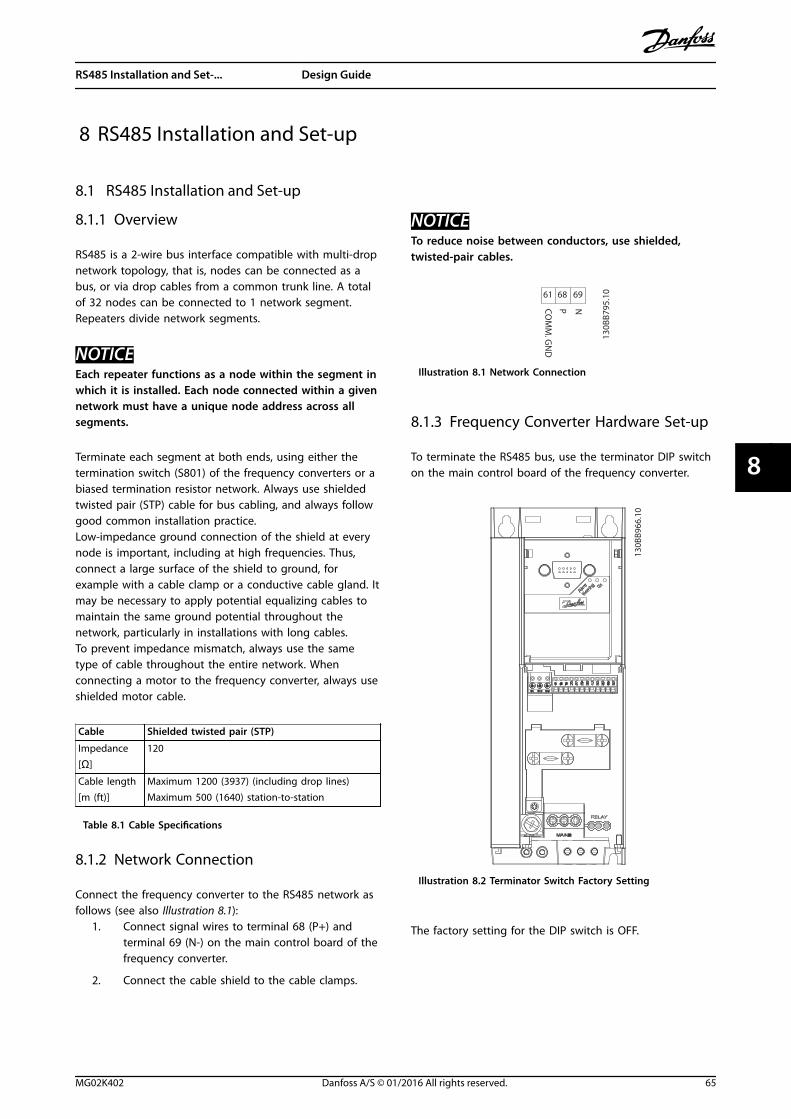
8 RS485 Installation and Set-up
8.1 RS485 Installation and Set-up
8.1.1 Overview
RS485 is a 2-wire bus interface compatible with multi-dropnetwork topology, that is, nodes can be connected as abus, or via drop cables from a common trunk line. A totalof 32 nodes can be connected to 1 network segment.Repeaters divide network segments.
NOTICEEach repeater functions as a node within the segment inwhich it is installed. Each node connected within a givennetwork must have a unique node address across allsegments.
Terminate each segment at both ends, using either thetermination switch (S801) of the frequency converters or abiased termination resistor network. Always use shieldedtwisted pair (STP) cable for bus cabling, and always followgood common installation practice.Low-impedance ground connection of the shield at everynode is important, including at high frequencies. Thus,connect a large surface of the shield to ground, forexample with a cable clamp or a conductive cable gland. Itmay be necessary to apply potential equalizing cables tomaintain the same ground potential throughout thenetwork, particularly in installations with long cables.To prevent impedance mismatch, always use the sametype of cable throughout the entire network. Whenconnecting a motor to the frequency converter, always useshielded motor cable.
Cable Shielded twisted pair (STP)
Impedance
[Ω]
120
Cable length[m (ft)]
Maximum 1200 (3937) (including drop lines)Maximum 500 (1640) station-to-station
Table 8.1 Cable Specifications
8.1.2 Network Connection
Connect the frequency converter to the RS485 network asfollows (see also Illustration 8.1):
1. Connect signal wires to terminal 68 (P+) andterminal 69 (N-) on the main control board of thefrequency converter.
2. Connect the cable shield to the cable clamps.
NOTICETo reduce noise between conductors, use shielded,twisted-pair cables.
61 68 69
NPCOM
M. G
ND
130B
B795
.10
Illustration 8.1 Network Connection
8.1.3 Frequency Converter Hardware Set-up
To terminate the RS485 bus, use the terminator DIP switchon the main control board of the frequency converter.
130B
B966
.10
Illustration 8.2 Terminator Switch Factory Setting
The factory setting for the DIP switch is OFF.
RS485 Installation and Set-... Design Guide
MG02K402 Danfoss A/S © 01/2016 All rights reserved. 65
8 8
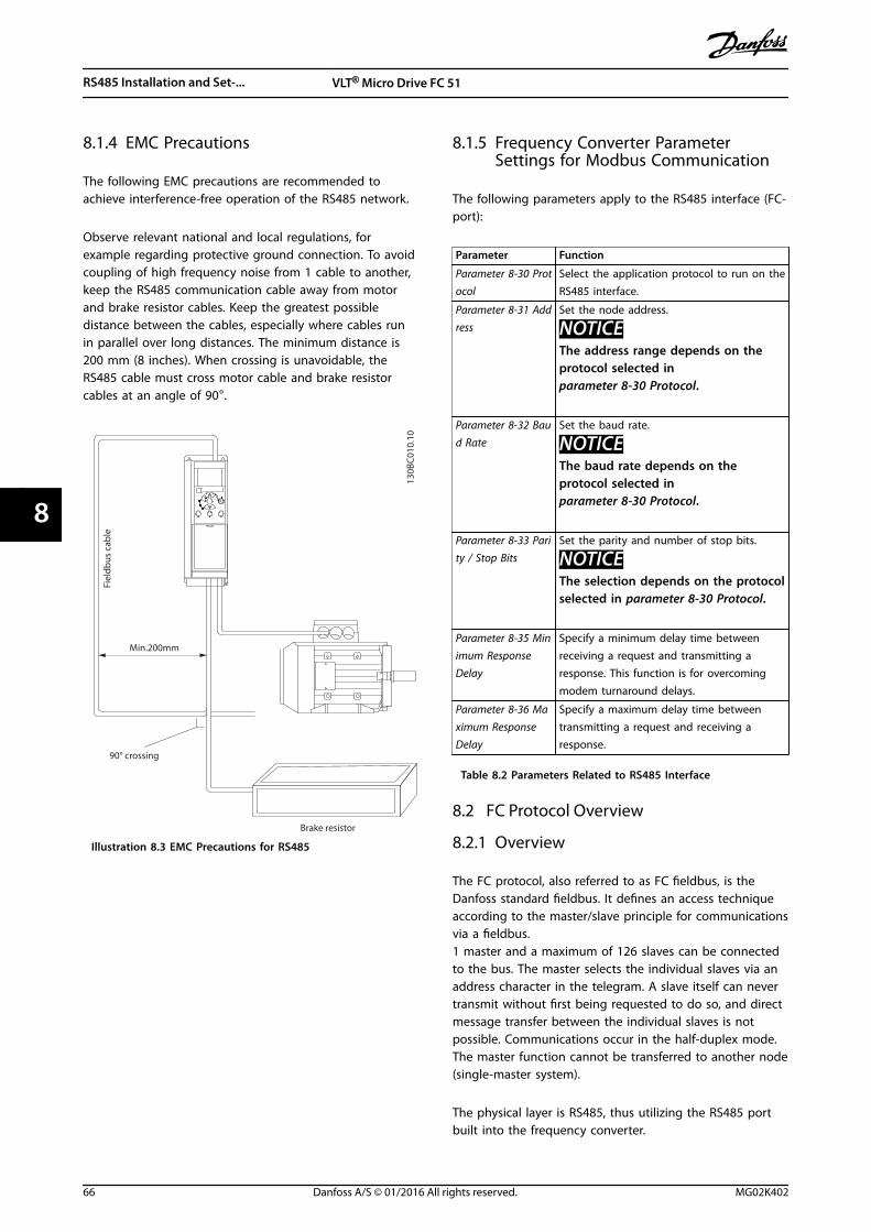
8.1.4 EMC Precautions
The following EMC precautions are recommended toachieve interference-free operation of the RS485 network.
Observe relevant national and local regulations, forexample regarding protective ground connection. To avoidcoupling of high frequency noise from 1 cable to another,keep the RS485 communication cable away from motorand brake resistor cables. Keep the greatest possibledistance between the cables, especially where cables runin parallel over long distances. The minimum distance is200 mm (8 inches). When crossing is unavoidable, theRS485 cable must cross motor cable and brake resistorcables at an angle of 90°.
Fiel
dbus
cab
le
Brake resistor
Min.200mm
90° crossing
130B
C01
0.10
Illustration 8.3 EMC Precautions for RS485
8.1.5 Frequency Converter ParameterSettings for Modbus Communication
The following parameters apply to the RS485 interface (FC-port):
Parameter Function
Parameter 8-30 Protocol
Select the application protocol to run on theRS485 interface.
Parameter 8-31 Address
Set the node address.
NOTICEThe address range depends on theprotocol selected inparameter 8-30 Protocol.
Parameter 8-32 Baud Rate
Set the baud rate.
NOTICEThe baud rate depends on theprotocol selected inparameter 8-30 Protocol.
Parameter 8-33 Parity / Stop Bits
Set the parity and number of stop bits.
NOTICEThe selection depends on the protocolselected in parameter 8-30 Protocol.
Parameter 8-35 Minimum ResponseDelay
Specify a minimum delay time betweenreceiving a request and transmitting aresponse. This function is for overcomingmodem turnaround delays.
Parameter 8-36 Maximum ResponseDelay
Specify a maximum delay time betweentransmitting a request and receiving aresponse.
Table 8.2 Parameters Related to RS485 Interface
8.2 FC Protocol Overview
8.2.1 Overview
The FC protocol, also referred to as FC fieldbus, is theDanfoss standard fieldbus. It defines an access techniqueaccording to the master/slave principle for communicationsvia a fieldbus.1 master and a maximum of 126 slaves can be connectedto the bus. The master selects the individual slaves via anaddress character in the telegram. A slave itself can nevertransmit without first being requested to do so, and directmessage transfer between the individual slaves is notpossible. Communications occur in the half-duplex mode.The master function cannot be transferred to another node(single-master system).
The physical layer is RS485, thus utilizing the RS485 portbuilt into the frequency converter.
RS485 Installation and Set-... VLT® Micro Drive FC 51
66 Danfoss A/S © 01/2016 All rights reserved. MG02K402
88
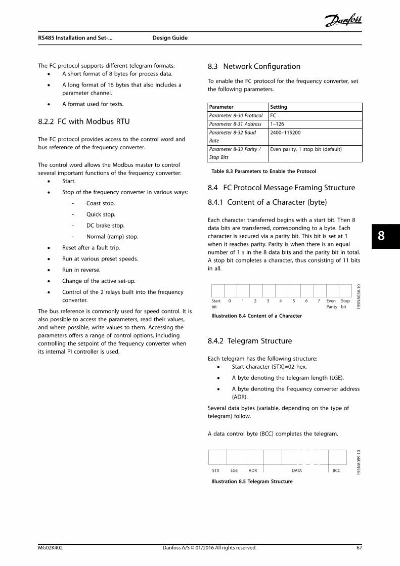
The FC protocol supports different telegram formats:• A short format of 8 bytes for process data.
• A long format of 16 bytes that also includes aparameter channel.
• A format used for texts.
8.2.2 FC with Modbus RTU
The FC protocol provides access to the control word andbus reference of the frequency converter.
The control word allows the Modbus master to controlseveral important functions of the frequency converter:
• Start.
• Stop of the frequency converter in various ways:
- Coast stop.
- Quick stop.
- DC brake stop.
- Normal (ramp) stop.
• Reset after a fault trip.
• Run at various preset speeds.
• Run in reverse.
• Change of the active set-up.
• Control of the 2 relays built into the frequencyconverter.
The bus reference is commonly used for speed control. It isalso possible to access the parameters, read their values,and where possible, write values to them. Accessing theparameters offers a range of control options, includingcontrolling the setpoint of the frequency converter whenits internal PI controller is used.
8.3 Network Configuration
To enable the FC protocol for the frequency converter, setthe following parameters.
Parameter Setting
Parameter 8-30 Protocol FC
Parameter 8-31 Address 1–126
Parameter 8-32 BaudRate
2400–115200
Parameter 8-33 Parity /Stop Bits
Even parity, 1 stop bit (default)
Table 8.3 Parameters to Enable the Protocol
8.4 FC Protocol Message Framing Structure
8.4.1 Content of a Character (byte)
Each character transferred begins with a start bit. Then 8data bits are transferred, corresponding to a byte. Eachcharacter is secured via a parity bit. This bit is set at 1when it reaches parity. Parity is when there is an equalnumber of 1 s in the 8 data bits and the parity bit in total.A stop bit completes a character, thus consisting of 11 bitsin all.
0 1 32 4 5 6 7
195N
A03
6.10
Startbit
Even StopParity bit
Illustration 8.4 Content of a Character
8.4.2 Telegram Structure
Each telegram has the following structure:• Start character (STX)=02 hex.
• A byte denoting the telegram length (LGE).
• A byte denoting the frequency converter address(ADR).
Several data bytes (variable, depending on the type oftelegram) follow.
A data control byte (BCC) completes the telegram.
STX LGE ADR DATA BCC
195N
A09
9.10
Illustration 8.5 Telegram Structure
RS485 Installation and Set-... Design Guide
MG02K402 Danfoss A/S © 01/2016 All rights reserved. 67
8 8
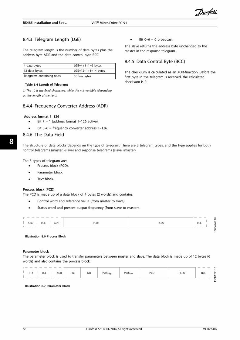
8.4.3 Telegram Length (LGE)
The telegram length is the number of data bytes plus theaddress byte ADR and the data control byte BCC.
4 data bytes LGE=4+1+1=6 bytes
12 data bytes LGE=12+1+1=14 bytes
Telegrams containing texts 101)+n bytes
Table 8.4 Length of Telegrams
1) The 10 is the fixed characters, while the n is variable (dependingon the length of the text).
8.4.4 Frequency Converter Address (ADR)
Address format 1–126• Bit 7 = 1 (address format 1–126 active).
• Bit 0–6 = frequency converter address 1–126.
• Bit 0–6 = 0 broadcast.
The slave returns the address byte unchanged to themaster in the response telegram.
8.4.5 Data Control Byte (BCC)
The checksum is calculated as an XOR-function. Before thefirst byte in the telegram is received, the calculatedchecksum is 0.
8.4.6 The Data Field
The structure of data blocks depends on the type of telegram. There are 3 telegram types, and the type applies for bothcontrol telegrams (master⇒slave) and response telegrams (slave⇒master).
The 3 types of telegram are:• Process block (PCD).
• Parameter block.
• Text block.
Process block (PCD)The PCD is made up of a data block of 4 bytes (2 words) and contains:
• Control word and reference value (from master to slave).
• Status word and present output frequency (from slave to master).
ADRLGESTX PCD1 PCD2 BCC
130B
A26
9.10
Illustration 8.6 Process Block
Parameter blockThe parameter block is used to transfer parameters between master and slave. The data block is made up of 12 bytes (6words) and also contains the process block.
PKE INDADRLGESTX PCD1 PCD2 BCC
130B
A27
1.10
PWEhigh PWElow
Illustration 8.7 Parameter Block
RS485 Installation and Set-... VLT® Micro Drive FC 51
68 Danfoss A/S © 01/2016 All rights reserved. MG02K402
88
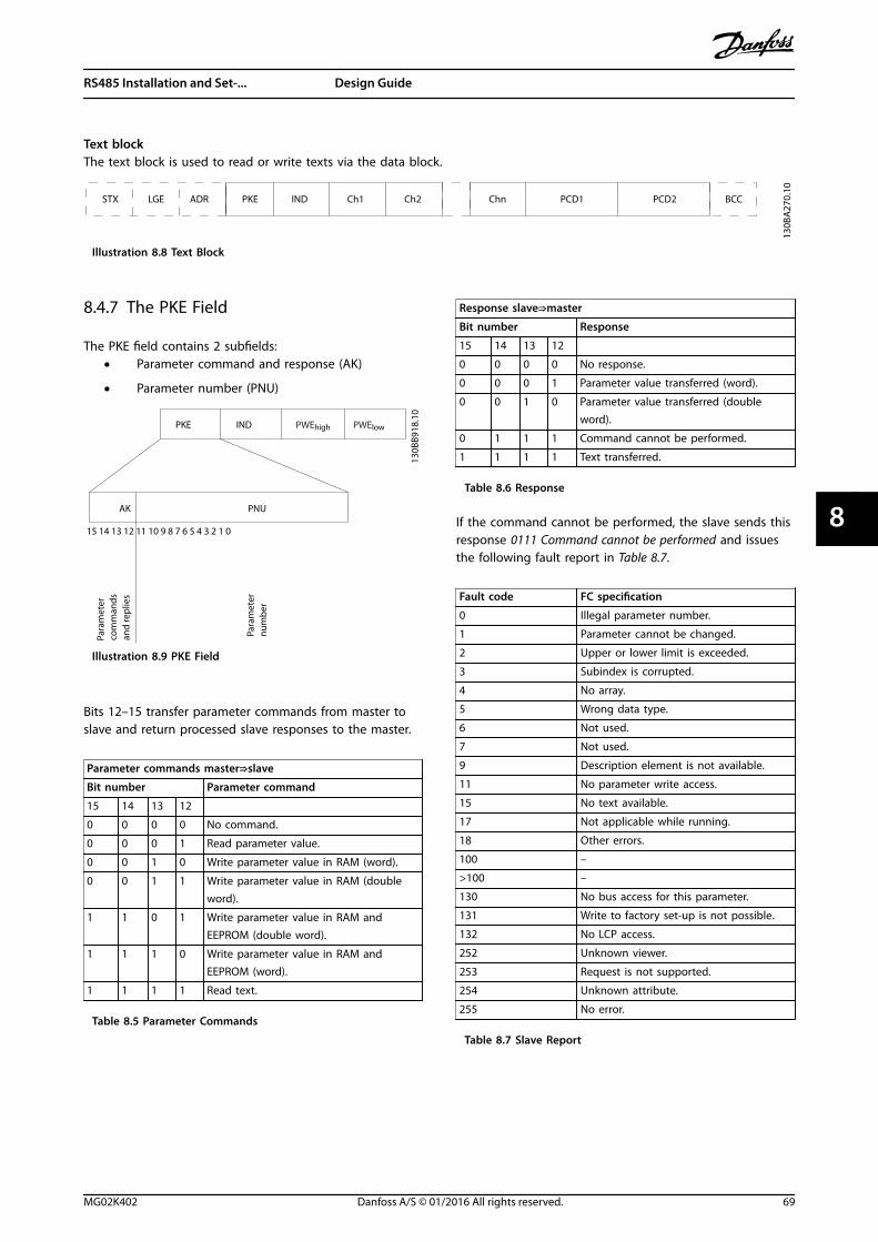
Text blockThe text block is used to read or write texts via the data block.
PKE IND
130B
A27
0.10
ADRLGESTX PCD1 PCD2 BCCCh1 Ch2 Chn
Illustration 8.8 Text Block
8.4.7 The PKE Field
The PKE field contains 2 subfields:• Parameter command and response (AK)
• Parameter number (PNU)
15 14 13 12 11 10 9 8 7 6 5 4 3 2 1 0
130B
B918
.10
PKE IND PWEhigh PWElow
AK PNU
Para
met
er
com
man
ds
and
rep
lies
Para
met
ernu
mb
er
Illustration 8.9 PKE Field
Bits 12–15 transfer parameter commands from master toslave and return processed slave responses to the master.
Parameter commands master⇒slave
Bit number Parameter command
15 14 13 12
0 0 0 0 No command.
0 0 0 1 Read parameter value.
0 0 1 0 Write parameter value in RAM (word).
0 0 1 1 Write parameter value in RAM (doubleword).
1 1 0 1 Write parameter value in RAM andEEPROM (double word).
1 1 1 0 Write parameter value in RAM andEEPROM (word).
1 1 1 1 Read text.
Table 8.5 Parameter Commands
Response slave⇒master
Bit number Response
15 14 13 12
0 0 0 0 No response.
0 0 0 1 Parameter value transferred (word).
0 0 1 0 Parameter value transferred (doubleword).
0 1 1 1 Command cannot be performed.
1 1 1 1 Text transferred.
Table 8.6 Response
If the command cannot be performed, the slave sends thisresponse 0111 Command cannot be performed and issuesthe following fault report in Table 8.7.
Fault code FC specification
0 Illegal parameter number.
1 Parameter cannot be changed.
2 Upper or lower limit is exceeded.
3 Subindex is corrupted.
4 No array.
5 Wrong data type.
6 Not used.
7 Not used.
9 Description element is not available.
11 No parameter write access.
15 No text available.
17 Not applicable while running.
18 Other errors.
100 –
>100 –
130 No bus access for this parameter.
131 Write to factory set-up is not possible.
132 No LCP access.
252 Unknown viewer.
253 Request is not supported.
254 Unknown attribute.
255 No error.
Table 8.7 Slave Report
RS485 Installation and Set-... Design Guide
MG02K402 Danfoss A/S © 01/2016 All rights reserved. 69
8 8
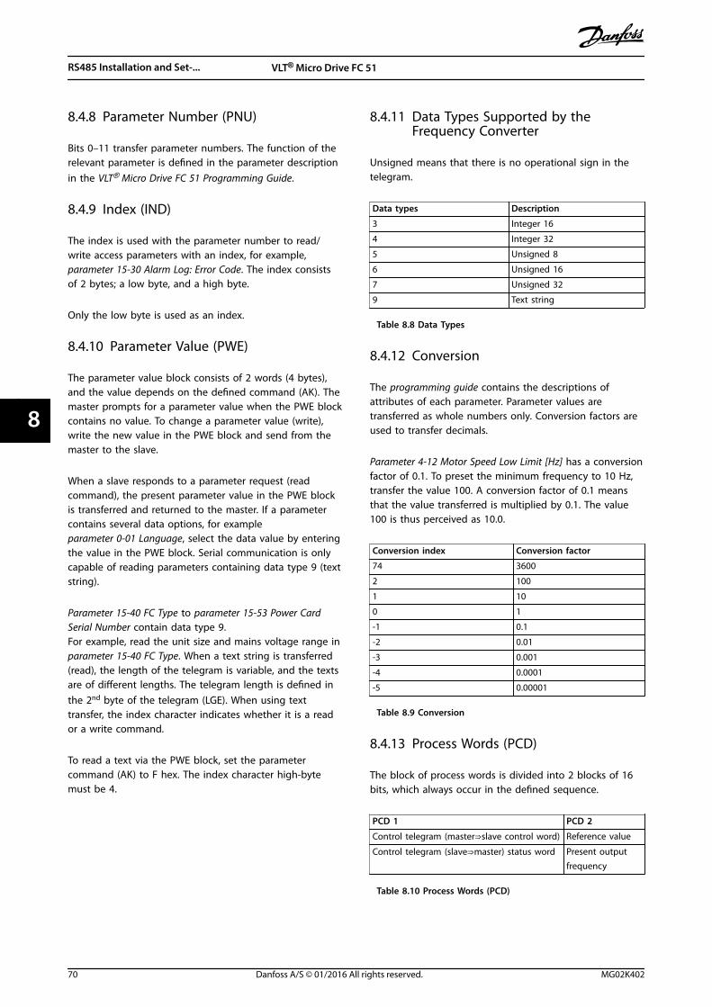
8.4.8 Parameter Number (PNU)
Bits 0–11 transfer parameter numbers. The function of therelevant parameter is defined in the parameter descriptionin the VLT® Micro Drive FC 51 Programming Guide.
8.4.9 Index (IND)
The index is used with the parameter number to read/write access parameters with an index, for example,parameter 15-30 Alarm Log: Error Code. The index consistsof 2 bytes; a low byte, and a high byte.
Only the low byte is used as an index.
8.4.10 Parameter Value (PWE)
The parameter value block consists of 2 words (4 bytes),and the value depends on the defined command (AK). Themaster prompts for a parameter value when the PWE blockcontains no value. To change a parameter value (write),write the new value in the PWE block and send from themaster to the slave.
When a slave responds to a parameter request (readcommand), the present parameter value in the PWE blockis transferred and returned to the master. If a parametercontains several data options, for exampleparameter 0-01 Language, select the data value by enteringthe value in the PWE block. Serial communication is onlycapable of reading parameters containing data type 9 (textstring).
Parameter 15-40 FC Type to parameter 15-53 Power CardSerial Number contain data type 9.For example, read the unit size and mains voltage range inparameter 15-40 FC Type. When a text string is transferred(read), the length of the telegram is variable, and the textsare of different lengths. The telegram length is defined inthe 2nd byte of the telegram (LGE). When using texttransfer, the index character indicates whether it is a reador a write command.
To read a text via the PWE block, set the parametercommand (AK) to F hex. The index character high-bytemust be 4.
8.4.11 Data Types Supported by theFrequency Converter
Unsigned means that there is no operational sign in thetelegram.
Data types Description
3 Integer 16
4 Integer 32
5 Unsigned 8
6 Unsigned 16
7 Unsigned 32
9 Text string
Table 8.8 Data Types
8.4.12 Conversion
The programming guide contains the descriptions ofattributes of each parameter. Parameter values aretransferred as whole numbers only. Conversion factors areused to transfer decimals.
Parameter 4-12 Motor Speed Low Limit [Hz] has a conversionfactor of 0.1. To preset the minimum frequency to 10 Hz,transfer the value 100. A conversion factor of 0.1 meansthat the value transferred is multiplied by 0.1. The value100 is thus perceived as 10.0.
Conversion index Conversion factor
74 3600
2 100
1 10
0 1
-1 0.1
-2 0.01
-3 0.001
-4 0.0001
-5 0.00001
Table 8.9 Conversion
8.4.13 Process Words (PCD)
The block of process words is divided into 2 blocks of 16bits, which always occur in the defined sequence.
PCD 1 PCD 2
Control telegram (master⇒slave control word) Reference value
Control telegram (slave⇒master) status word Present outputfrequency
Table 8.10 Process Words (PCD)
RS485 Installation and Set-... VLT® Micro Drive FC 51
70 Danfoss A/S © 01/2016 All rights reserved. MG02K402
88
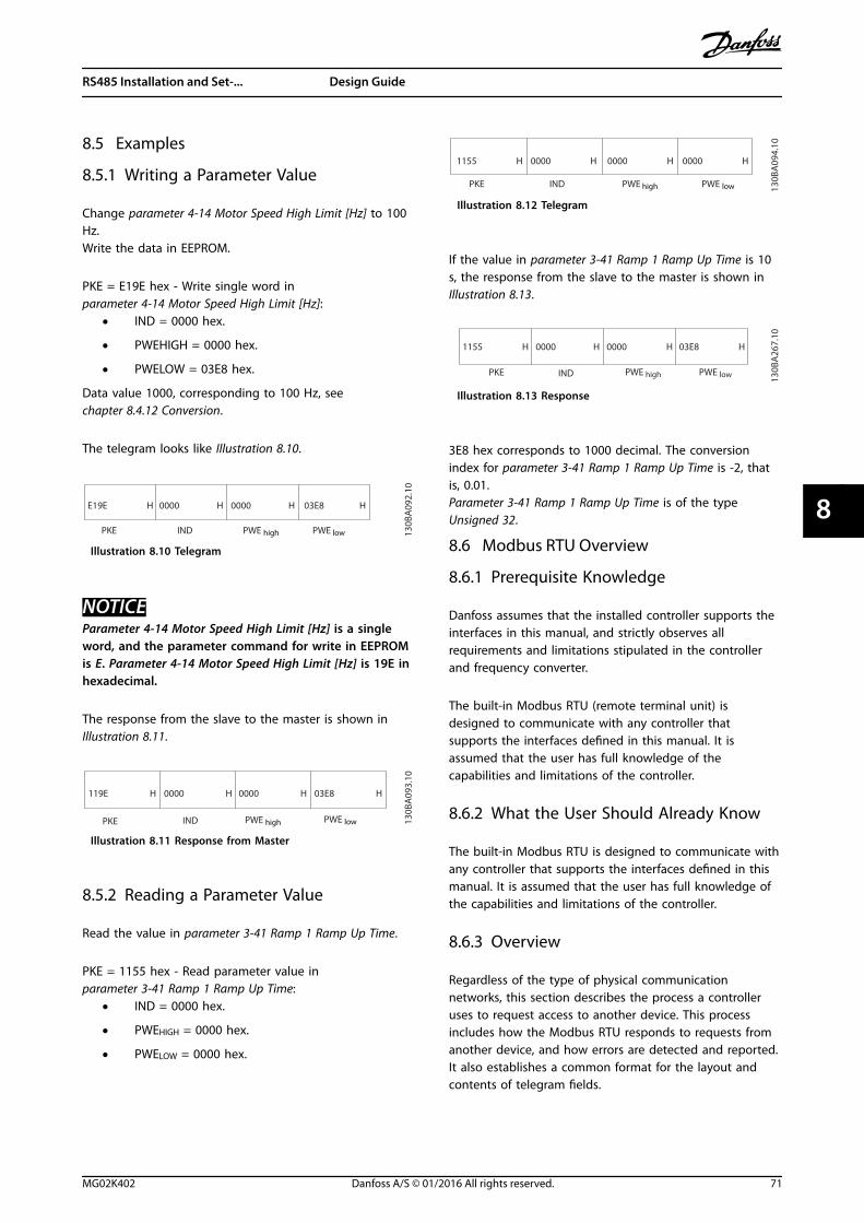
8.5 Examples
8.5.1 Writing a Parameter Value
Change parameter 4-14 Motor Speed High Limit [Hz] to 100Hz.Write the data in EEPROM.
PKE = E19E hex - Write single word inparameter 4-14 Motor Speed High Limit [Hz]:
• IND = 0000 hex.
• PWEHIGH = 0000 hex.
• PWELOW = 03E8 hex.
Data value 1000, corresponding to 100 Hz, seechapter 8.4.12 Conversion.
The telegram looks like Illustration 8.10.
E19E H
PKE IND PWE high PWE low
0000 H 0000 H 03E8 H
130B
A09
2.10
Illustration 8.10 Telegram
NOTICEParameter 4-14 Motor Speed High Limit [Hz] is a singleword, and the parameter command for write in EEPROMis E. Parameter 4-14 Motor Speed High Limit [Hz] is 19E inhexadecimal.
The response from the slave to the master is shown inIllustration 8.11.
119E H
PKE IND PWE high PWE low
0000 H 0000 H 03E8 H
130B
A09
3.10
Illustration 8.11 Response from Master
8.5.2 Reading a Parameter Value
Read the value in parameter 3-41 Ramp 1 Ramp Up Time.
PKE = 1155 hex - Read parameter value inparameter 3-41 Ramp 1 Ramp Up Time:
• IND = 0000 hex.
• PWEHIGH = 0000 hex.
• PWELOW = 0000 hex.
1155 H
PKE IND PWE high PWE low
0000 H 0000 H 0000 H
130B
A09
4.10
Illustration 8.12 Telegram
If the value in parameter 3-41 Ramp 1 Ramp Up Time is 10s, the response from the slave to the master is shown inIllustration 8.13.
130B
A26
7.10
1155 H
PKE IND
0000 H 0000 H 03E8 H
PWE high PWE low
Illustration 8.13 Response
3E8 hex corresponds to 1000 decimal. The conversionindex for parameter 3-41 Ramp 1 Ramp Up Time is -2, thatis, 0.01.Parameter 3-41 Ramp 1 Ramp Up Time is of the typeUnsigned 32.
8.6 Modbus RTU Overview
8.6.1 Prerequisite Knowledge
Danfoss assumes that the installed controller supports theinterfaces in this manual, and strictly observes allrequirements and limitations stipulated in the controllerand frequency converter.
The built-in Modbus RTU (remote terminal unit) isdesigned to communicate with any controller thatsupports the interfaces defined in this manual. It isassumed that the user has full knowledge of thecapabilities and limitations of the controller.
8.6.2 What the User Should Already Know
The built-in Modbus RTU is designed to communicate withany controller that supports the interfaces defined in thismanual. It is assumed that the user has full knowledge ofthe capabilities and limitations of the controller.
8.6.3 Overview
Regardless of the type of physical communicationnetworks, this section describes the process a controlleruses to request access to another device. This processincludes how the Modbus RTU responds to requests fromanother device, and how errors are detected and reported.It also establishes a common format for the layout andcontents of telegram fields.
RS485 Installation and Set-... Design Guide
MG02K402 Danfoss A/S © 01/2016 All rights reserved. 71
8 8
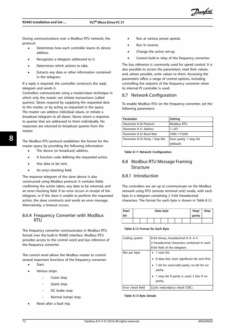
During communications over a Modbus RTU network, theprotocol:
• Determines how each controller learns its deviceaddress.
• Recognizes a telegram addressed to it.
• Determines which actions to take.
• Extracts any data or other information containedin the telegram.
If a reply is required, the controller constructs the replytelegram and sends it.Controllers communicate using a master/slave technique inwhich only the master can initiate transactions (calledqueries). Slaves respond by supplying the requested datato the master, or by acting as requested in the query.The master can address individual slaves, or initiate abroadcast telegram to all slaves. Slaves return a responseto queries that are addressed to them individually. Noresponses are returned to broadcast queries from themaster.
The Modbus RTU protocol establishes the format for themaster query by providing the following information:
• The device (or broadcast) address.
• A function code defining the requested action.
• Any data to be sent.
• An error-checking field.
The response telegram of the slave device is alsoconstructed using Modbus protocol. It contains fieldsconfirming the action taken, any data to be returned, andan error-checking field. If an error occurs in receipt of thetelegram, or if the slave is unable to perform the requestedaction, the slave constructs and sends an error message.Alternatively, a timeout occurs.
8.6.4 Frequency Converter with ModbusRTU
The frequency converter communicates in Modbus RTUformat over the built-in RS485 interface. Modbus RTUprovides access to the control word and bus reference ofthe frequency converter.
The control word allows the Modbus master to controlseveral important functions of the frequency converter:
• Start.
• Various stops:
- Coast stop.
- Quick stop.
- DC brake stop.
- Normal (ramp) stop.
• Reset after a fault trip.
• Run at various preset speeds.
• Run in reverse.
• Change the active set-up.
• Control built-in relay of the frequency converter.
The bus reference is commonly used for speed control. It isalso possible to access the parameters, read their values,and, where possible, write values to them. Accessing theparameters offers a range of control options, includingcontrolling the setpoint of the frequency converter whenits internal PI controller is used.
8.7 Network Configuration
To enable Modbus RTU on the frequency converter, set thefollowing parameters:
Parameter Setting
Parameter 8-30 Protocol Modbus RTU
Parameter 8-31 Address 1–247
Parameter 8-32 Baud Rate 2400–115200
Parameter 8-33 Parity / Stop Bits Even parity, 1 stop bit(default)
Table 8.11 Network Configuration
8.8 Modbus RTU Message FramingStructure
8.8.1 Introduction
The controllers are set up to communicate on the Modbusnetwork using RTU (remote terminal unit) mode, with eachbyte in a telegram containing 2 4-bit hexadecimalcharacters. The format for each byte is shown in Table 8.12.
Startbit
Data byte Stop/parity
Stop
Table 8.12 Format for Each Byte
Coding system 8-bit binary, hexadecimal 0–9, A–F.2 hexadecimal characters contained in each8-bit field of the telegram.
Bits per byte • 1 start bit.
• 8 data bits, least significant bit sent first.
• 1 bit for even/odd parity; no bit for noparity.
• 1 stop bit if parity is used; 2 bits if noparity.
Error check field Cyclic redundancy check (CRC).
Table 8.13 Byte Details
RS485 Installation and Set-... VLT® Micro Drive FC 51
72 Danfoss A/S © 01/2016 All rights reserved. MG02K402
88
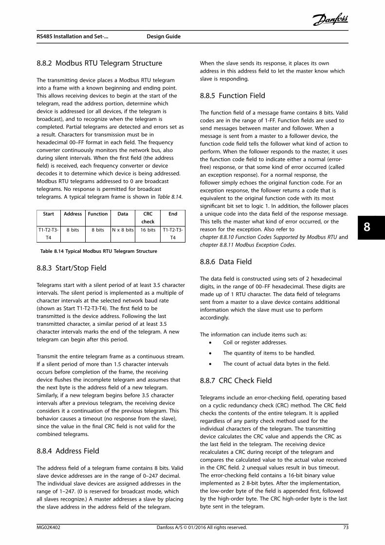
8.8.2 Modbus RTU Telegram Structure
The transmitting device places a Modbus RTU telegraminto a frame with a known beginning and ending point.This allows receiving devices to begin at the start of thetelegram, read the address portion, determine whichdevice is addressed (or all devices, if the telegram isbroadcast), and to recognize when the telegram iscompleted. Partial telegrams are detected and errors set asa result. Characters for transmission must be inhexadecimal 00–FF format in each field. The frequencyconverter continuously monitors the network bus, alsoduring silent intervals. When the first field (the addressfield) is received, each frequency converter or devicedecodes it to determine which device is being addressed.Modbus RTU telegrams addressed to 0 are broadcasttelegrams. No response is permitted for broadcasttelegrams. A typical telegram frame is shown in Table 8.14.
Start Address Function Data CRCcheck
End
T1-T2-T3-T4
8 bits 8 bits N x 8 bits 16 bits T1-T2-T3-T4
Table 8.14 Typical Modbus RTU Telegram Structure
8.8.3 Start/Stop Field
Telegrams start with a silent period of at least 3.5 characterintervals. The silent period is implemented as a multiple ofcharacter intervals at the selected network baud rate(shown as Start T1-T2-T3-T4). The first field to betransmitted is the device address. Following the lasttransmitted character, a similar period of at least 3.5character intervals marks the end of the telegram. A newtelegram can begin after this period.
Transmit the entire telegram frame as a continuous stream.If a silent period of more than 1.5 character intervalsoccurs before completion of the frame, the receivingdevice flushes the incomplete telegram and assumes thatthe next byte is the address field of a new telegram.Similarly, if a new telegram begins before 3.5 characterintervals after a previous telegram, the receiving deviceconsiders it a continuation of the previous telegram. Thisbehavior causes a timeout (no response from the slave),since the value in the final CRC field is not valid for thecombined telegrams.
8.8.4 Address Field
The address field of a telegram frame contains 8 bits. Validslave device addresses are in the range of 0–247 decimal.The individual slave devices are assigned addresses in therange of 1–247. (0 is reserved for broadcast mode, whichall slaves recognize.) A master addresses a slave by placingthe slave address in the address field of the telegram.
When the slave sends its response, it places its ownaddress in this address field to let the master know whichslave is responding.
8.8.5 Function Field
The function field of a message frame contains 8 bits. Validcodes are in the range of 1-FF. Function fields are used tosend messages between master and follower. When amessage is sent from a master to a follower device, thefunction code field tells the follower what kind of action toperform. When the follower responds to the master, it usesthe function code field to indicate either a normal (error-free) response, or that some kind of error occurred (calledan exception response). For a normal response, thefollower simply echoes the original function code. For anexception response, the follower returns a code that isequivalent to the original function code with its mostsignificant bit set to logic 1. In addition, the follower placesa unique code into the data field of the response message.This tells the master what kind of error occurred, or thereason for the exception. Also refer tochapter 8.8.10 Function Codes Supported by Modbus RTU andchapter 8.8.11 Modbus Exception Codes.
8.8.6 Data Field
The data field is constructed using sets of 2 hexadecimaldigits, in the range of 00–FF hexadecimal. These digits aremade up of 1 RTU character. The data field of telegramssent from a master to a slave device contains additionalinformation which the slave must use to performaccordingly.
The information can include items such as:• Coil or register addresses.
• The quantity of items to be handled.
• The count of actual data bytes in the field.
8.8.7 CRC Check Field
Telegrams include an error-checking field, operating basedon a cyclic redundancy check (CRC) method. The CRC fieldchecks the contents of the entire telegram. It is appliedregardless of any parity check method used for theindividual characters of the telegram. The transmittingdevice calculates the CRC value and appends the CRC asthe last field in the telegram. The receiving devicerecalculates a CRC during receipt of the telegram andcompares the calculated value to the actual value receivedin the CRC field. 2 unequal values result in bus timeout.The error-checking field contains a 16-bit binary valueimplemented as 2 8-bit bytes. After the implementation,the low-order byte of the field is appended first, followedby the high-order byte. The CRC high-order byte is the lastbyte sent in the telegram.
RS485 Installation and Set-... Design Guide
MG02K402 Danfoss A/S © 01/2016 All rights reserved. 73
8 8
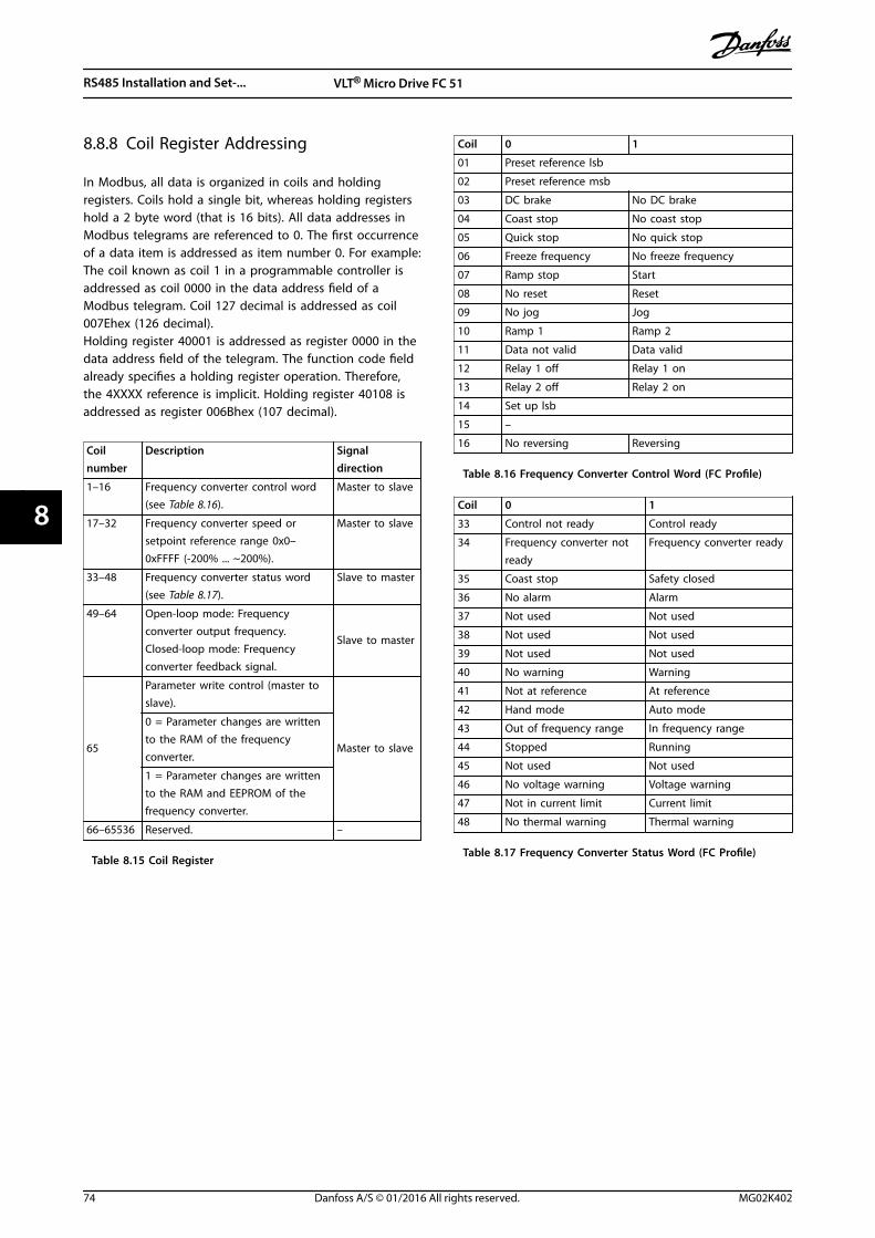
8.8.8 Coil Register Addressing
In Modbus, all data is organized in coils and holdingregisters. Coils hold a single bit, whereas holding registershold a 2 byte word (that is 16 bits). All data addresses inModbus telegrams are referenced to 0. The first occurrenceof a data item is addressed as item number 0. For example:The coil known as coil 1 in a programmable controller isaddressed as coil 0000 in the data address field of aModbus telegram. Coil 127 decimal is addressed as coil007Ehex (126 decimal).Holding register 40001 is addressed as register 0000 in thedata address field of the telegram. The function code fieldalready specifies a holding register operation. Therefore,the 4XXXX reference is implicit. Holding register 40108 isaddressed as register 006Bhex (107 decimal).
Coilnumber
Description Signaldirection
1–16 Frequency converter control word(see Table 8.16).
Master to slave
17–32 Frequency converter speed orsetpoint reference range 0x0–0xFFFF (-200% ... ~200%).
Master to slave
33–48 Frequency converter status word(see Table 8.17).
Slave to master
49–64 Open-loop mode: Frequencyconverter output frequency.Closed-loop mode: Frequencyconverter feedback signal.
Slave to master
65
Parameter write control (master toslave).
Master to slave
0 = Parameter changes are writtento the RAM of the frequencyconverter.
1 = Parameter changes are writtento the RAM and EEPROM of thefrequency converter.
66–65536 Reserved. –
Table 8.15 Coil Register
Coil 0 1
01 Preset reference lsb
02 Preset reference msb
03 DC brake No DC brake
04 Coast stop No coast stop
05 Quick stop No quick stop
06 Freeze frequency No freeze frequency
07 Ramp stop Start
08 No reset Reset
09 No jog Jog
10 Ramp 1 Ramp 2
11 Data not valid Data valid
12 Relay 1 off Relay 1 on
13 Relay 2 off Relay 2 on
14 Set up lsb
15 –
16 No reversing Reversing
Table 8.16 Frequency Converter Control Word (FC Profile)
Coil 0 1
33 Control not ready Control ready
34 Frequency converter notready
Frequency converter ready
35 Coast stop Safety closed
36 No alarm Alarm
37 Not used Not used
38 Not used Not used
39 Not used Not used
40 No warning Warning
41 Not at reference At reference
42 Hand mode Auto mode
43 Out of frequency range In frequency range
44 Stopped Running
45 Not used Not used
46 No voltage warning Voltage warning
47 Not in current limit Current limit
48 No thermal warning Thermal warning
Table 8.17 Frequency Converter Status Word (FC Profile)
RS485 Installation and Set-... VLT® Micro Drive FC 51
74 Danfoss A/S © 01/2016 All rights reserved. MG02K402
88
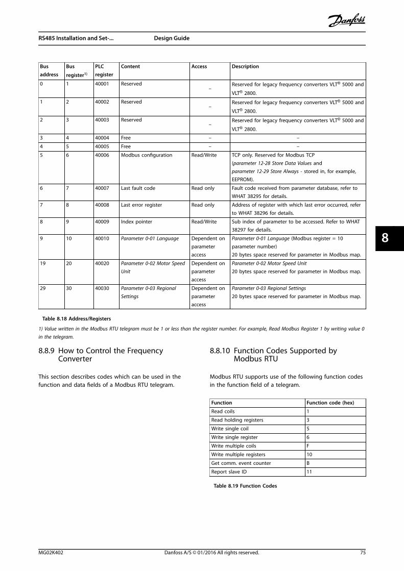
Busaddress
Bus
register1)
PLCregister
Content Access Description
0 1 40001 Reserved–
Reserved for legacy frequency converters VLT® 5000 and
VLT® 2800.
1 2 40002 Reserved–
Reserved for legacy frequency converters VLT® 5000 and
VLT® 2800.
2 3 40003 Reserved–
Reserved for legacy frequency converters VLT® 5000 and
VLT® 2800.
3 4 40004 Free – –
4 5 40005 Free – –
5 6 40006 Modbus configuration Read/Write TCP only. Reserved for Modbus TCP(parameter 12-28 Store Data Values andparameter 12-29 Store Always - stored in, for example,EEPROM).
6 7 40007 Last fault code Read only Fault code received from parameter database, refer toWHAT 38295 for details.
7 8 40008 Last error register Read only Address of register with which last error occurred, referto WHAT 38296 for details.
8 9 40009 Index pointer Read/Write Sub index of parameter to be accessed. Refer to WHAT38297 for details.
9 10 40010 Parameter 0-01 Language Dependent onparameteraccess
Parameter 0-01 Language (Modbus register = 10parameter number)20 bytes space reserved for parameter in Modbus map.
19 20 40020 Parameter 0-02 Motor SpeedUnit
Dependent onparameteraccess
Parameter 0-02 Motor Speed Unit20 bytes space reserved for parameter in Modbus map.
29 30 40030 Parameter 0-03 RegionalSettings
Dependent onparameteraccess
Parameter 0-03 Regional Settings20 bytes space reserved for parameter in Modbus map.
Table 8.18 Address/Registers
1) Value written in the Modbus RTU telegram must be 1 or less than the register number. For example, Read Modbus Register 1 by writing value 0in the telegram.
8.8.9 How to Control the FrequencyConverter
This section describes codes which can be used in thefunction and data fields of a Modbus RTU telegram.
8.8.10 Function Codes Supported byModbus RTU
Modbus RTU supports use of the following function codesin the function field of a telegram.
Function Function code (hex)
Read coils 1
Read holding registers 3
Write single coil 5
Write single register 6
Write multiple coils F
Write multiple registers 10
Get comm. event counter B
Report slave ID 11
Table 8.19 Function Codes
RS485 Installation and Set-... Design Guide
MG02K402 Danfoss A/S © 01/2016 All rights reserved. 75
8 8
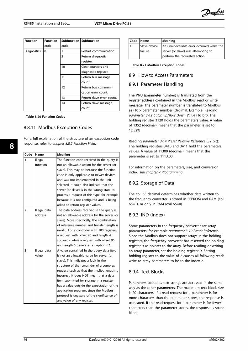
Function Functioncode
Subfunctioncode
Subfunction
Diagnostics 8 1 Restart communication.
2 Return diagnosticregister.
10 Clear counters anddiagnostic register.
11 Return bus messagecount.
12 Return bus communi-cation error count.
13 Return slave error count.
14 Return slave messagecount.
Table 8.20 Function Codes
8.8.11 Modbus Exception Codes
For a full explanation of the structure of an exception coderesponse, refer to chapter 8.8.5 Function Field.
Code Name Meaning
1 Illegalfunction
The function code received in the query isnot an allowable action for the server (orslave). This may be because the functioncode is only applicable to newer devicesand was not implemented in the unitselected. It could also indicate that theserver (or slave) is in the wrong state toprocess a request of this type, for examplebecause it is not configured and is beingasked to return register values.
2 Illegal dataaddress
The data address received in the query isnot an allowable address for the server (orslave). More specifically, the combinationof reference number and transfer length isinvalid. For a controller with 100 registers,a request with offset 96 and length 4succeeds, while a request with offset 96and length 5 generates exception 02.
3 Illegal datavalue
A value contained in the query data fieldis not an allowable value for server (orslave). This indicates a fault in thestructure of the remainder of a complexrequest, such as that the implied length isincorrect. It does NOT mean that a dataitem submitted for storage in a registerhas a value outside the expectation of theapplication program, since the Modbusprotocol is unaware of the significance ofany value of any register.
Code Name Meaning
4 Slave devicefailure
An unrecoverable error occurred while theserver (or slave) was attempting toperform the requested action.
Table 8.21 Modbus Exception Codes
8.9 How to Access Parameters
8.9.1 Parameter Handling
The PNU (parameter number) is translated from theregister address contained in the Modbus read or writemessage. The parameter number is translated to Modbusas (10 x parameter number) decimal. Example: Readingparameter 3-12 Catch up/slow Down Value (16 bit): Theholding register 3120 holds the parameters value. A valueof 1352 (decimal), means that the parameter is set to12.52%
Reading parameter 3-14 Preset Relative Reference (32 bit):The holding registers 3410 and 3411 hold the parametersvalues. A value of 11300 (decimal), means that theparameter is set to 1113.00.
For information on the parameters, size, and conversionindex, see chapter 7 Programming.
8.9.2 Storage of Data
The coil 65 decimal determines whether data written tothe frequency converter is stored in EEPROM and RAM (coil65=1), or only in RAM (coil 65=0).
8.9.3 IND (Index)
Some parameters in the frequency converter are arrayparameters, for example parameter 3-10 Preset Reference.Since the Modbus does not support arrays in the holdingregisters, the frequency converter has reserved the holdingregister 9 as pointer to the array. Before reading or writingan array parameter, set the holding register 9. Settingholding register to the value of 2 causes all following read/write to array parameters to be to the index 2.
8.9.4 Text Blocks
Parameters stored as text strings are accessed in the sameway as the other parameters. The maximum text block sizeis 20 characters. If a read request for a parameter is formore characters than the parameter stores, the response istruncated. If the read request for a parameter is for fewercharacters than the parameter stores, the response is spacefilled.
RS485 Installation and Set-... VLT® Micro Drive FC 51
76 Danfoss A/S © 01/2016 All rights reserved. MG02K402
88
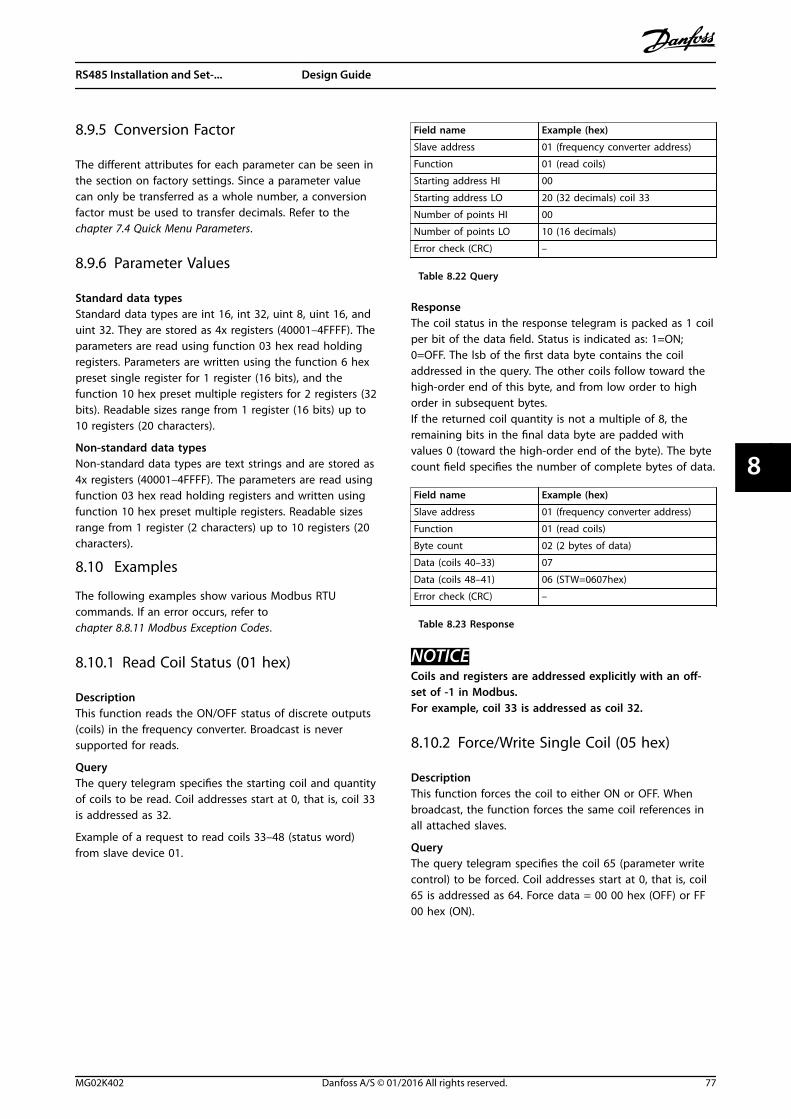
8.9.5 Conversion Factor
The different attributes for each parameter can be seen inthe section on factory settings. Since a parameter valuecan only be transferred as a whole number, a conversionfactor must be used to transfer decimals. Refer to thechapter 7.4 Quick Menu Parameters.
8.9.6 Parameter Values
Standard data typesStandard data types are int 16, int 32, uint 8, uint 16, anduint 32. They are stored as 4x registers (40001–4FFFF). Theparameters are read using function 03 hex read holdingregisters. Parameters are written using the function 6 hexpreset single register for 1 register (16 bits), and thefunction 10 hex preset multiple registers for 2 registers (32bits). Readable sizes range from 1 register (16 bits) up to10 registers (20 characters).
Non-standard data typesNon-standard data types are text strings and are stored as4x registers (40001–4FFFF). The parameters are read usingfunction 03 hex read holding registers and written usingfunction 10 hex preset multiple registers. Readable sizesrange from 1 register (2 characters) up to 10 registers (20characters).
8.10 Examples
The following examples show various Modbus RTUcommands. If an error occurs, refer tochapter 8.8.11 Modbus Exception Codes.
8.10.1 Read Coil Status (01 hex)
DescriptionThis function reads the ON/OFF status of discrete outputs(coils) in the frequency converter. Broadcast is neversupported for reads.
QueryThe query telegram specifies the starting coil and quantityof coils to be read. Coil addresses start at 0, that is, coil 33is addressed as 32.
Example of a request to read coils 33–48 (status word)from slave device 01.
Field name Example (hex)
Slave address 01 (frequency converter address)
Function 01 (read coils)
Starting address HI 00
Starting address LO 20 (32 decimals) coil 33
Number of points HI 00
Number of points LO 10 (16 decimals)
Error check (CRC) –
Table 8.22 Query
ResponseThe coil status in the response telegram is packed as 1 coilper bit of the data field. Status is indicated as: 1=ON;0=OFF. The lsb of the first data byte contains the coiladdressed in the query. The other coils follow toward thehigh-order end of this byte, and from low order to highorder in subsequent bytes.If the returned coil quantity is not a multiple of 8, theremaining bits in the final data byte are padded withvalues 0 (toward the high-order end of the byte). The bytecount field specifies the number of complete bytes of data.
Field name Example (hex)
Slave address 01 (frequency converter address)
Function 01 (read coils)
Byte count 02 (2 bytes of data)
Data (coils 40–33) 07
Data (coils 48–41) 06 (STW=0607hex)
Error check (CRC) –
Table 8.23 Response
NOTICECoils and registers are addressed explicitly with an off-set of -1 in Modbus.For example, coil 33 is addressed as coil 32.
8.10.2 Force/Write Single Coil (05 hex)
DescriptionThis function forces the coil to either ON or OFF. Whenbroadcast, the function forces the same coil references inall attached slaves.
QueryThe query telegram specifies the coil 65 (parameter writecontrol) to be forced. Coil addresses start at 0, that is, coil65 is addressed as 64. Force data = 00 00 hex (OFF) or FF00 hex (ON).
RS485 Installation and Set-... Design Guide
MG02K402 Danfoss A/S © 01/2016 All rights reserved. 77
8 8
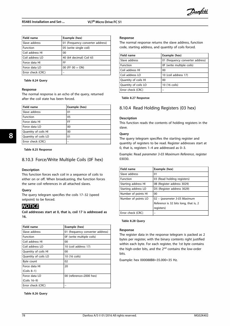
Field name Example (hex)
Slave address 01 (Frequency converter address)
Function 05 (write single coil)
Coil address HI 00
Coil address LO 40 (64 decimal) Coil 65
Force data HI FF
Force data LO 00 (FF 00 = ON)
Error check (CRC) –
Table 8.24 Query
ResponseThe normal response is an echo of the query, returnedafter the coil state has been forced.
Field name Example (hex)
Slave address 01
Function 05
Force data HI FF
Force data LO 00
Quantity of coils HI 00
Quantity of coils LO 01
Error check (CRC) –
Table 8.25 Response
8.10.3 Force/Write Multiple Coils (0F hex)
DescriptionThis function forces each coil in a sequence of coils toeither on or off. When broadcasting, the function forcesthe same coil references in all attached slaves.
QueryThe query telegram specifies the coils 17–32 (speedsetpoint) to be forced.
NOTICECoil addresses start at 0, that is, coil 17 is addressed as16.
Field name Example (hex)
Slave address 01 (frequency converter address)
Function 0F (write multiple coils)
Coil address HI 00
Coil address LO 10 (coil address 17)
Quantity of coils HI 00
Quantity of coils LO 10 (16 coils)
Byte count 02
Force data HI(Coils 8–1)
20
Force data LO(Coils 16–9)
00 (reference=2000 hex)
Error check (CRC) –
Table 8.26 Query
ResponseThe normal response returns the slave address, functioncode, starting address, and quantity of coils forced.
Field name Example (hex)
Slave address 01 (frequency converter address)
Function 0F (write multiple coils)
Coil address HI 00
Coil address LO 10 (coil address 17)
Quantity of coils HI 00
Quantity of coils LO 10 (16 coils)
Error check (CRC) –
Table 8.27 Response
8.10.4 Read Holding Registers (03 hex)
DescriptionThis function reads the contents of holding registers in theslave.
QueryThe query telegram specifies the starting register andquantity of registers to be read. Register addresses start at0, that is, registers 1–4 are addressed as 0–3.
Example: Read parameter 3-03 Maximum Reference, register03030.
Field name Example (hex)
Slave address 01
Function 03 (Read holding registers)
Starting address HI 0B (Register address 3029)
Starting address LO D5 (Register address 3029)
Number of points HI 00
Number of points LO 02 – (parameter 3-03 MaximumReference is 32 bits long, that is, 2registers)
Error check (CRC) –
Table 8.28 Query
ResponseThe register data in the response telegram is packed as 2bytes per register, with the binary contents right justifiedwithin each byte. For each register, the 1st byte containsthe high-order bits, and the 2nd contains the low-orderbits.
Example: hex 000088B8=35.000=35 Hz.
RS485 Installation and Set-... VLT® Micro Drive FC 51
78 Danfoss A/S © 01/2016 All rights reserved. MG02K402
88
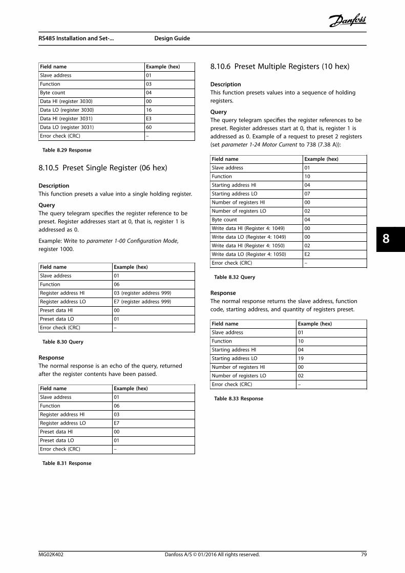
Field name Example (hex)
Slave address 01
Function 03
Byte count 04
Data HI (register 3030) 00
Data LO (register 3030) 16
Data HI (register 3031) E3
Data LO (register 3031) 60
Error check (CRC) –
Table 8.29 Response
8.10.5 Preset Single Register (06 hex)
DescriptionThis function presets a value into a single holding register.
QueryThe query telegram specifies the register reference to bepreset. Register addresses start at 0, that is, register 1 isaddressed as 0.
Example: Write to parameter 1-00 Configuration Mode,register 1000.
Field name Example (hex)
Slave address 01
Function 06
Register address HI 03 (register address 999)
Register address LO E7 (register address 999)
Preset data HI 00
Preset data LO 01
Error check (CRC) –
Table 8.30 Query
ResponseThe normal response is an echo of the query, returnedafter the register contents have been passed.
Field name Example (hex)
Slave address 01
Function 06
Register address HI 03
Register address LO E7
Preset data HI 00
Preset data LO 01
Error check (CRC) –
Table 8.31 Response
8.10.6 Preset Multiple Registers (10 hex)
DescriptionThis function presets values into a sequence of holdingregisters.
QueryThe query telegram specifies the register references to bepreset. Register addresses start at 0, that is, register 1 isaddressed as 0. Example of a request to preset 2 registers(set parameter 1-24 Motor Current to 738 (7.38 A)):
Field name Example (hex)
Slave address 01
Function 10
Starting address HI 04
Starting address LO 07
Number of registers HI 00
Number of registers LO 02
Byte count 04
Write data HI (Register 4: 1049) 00
Write data LO (Register 4: 1049) 00
Write data HI (Register 4: 1050) 02
Write data LO (Register 4: 1050) E2
Error check (CRC) –
Table 8.32 Query
ResponseThe normal response returns the slave address, functioncode, starting address, and quantity of registers preset.
Field name Example (hex)
Slave address 01
Function 10
Starting address HI 04
Starting address LO 19
Number of registers HI 00
Number of registers LO 02
Error check (CRC) –
Table 8.33 Response
RS485 Installation and Set-... Design Guide
MG02K402 Danfoss A/S © 01/2016 All rights reserved. 79
8 8
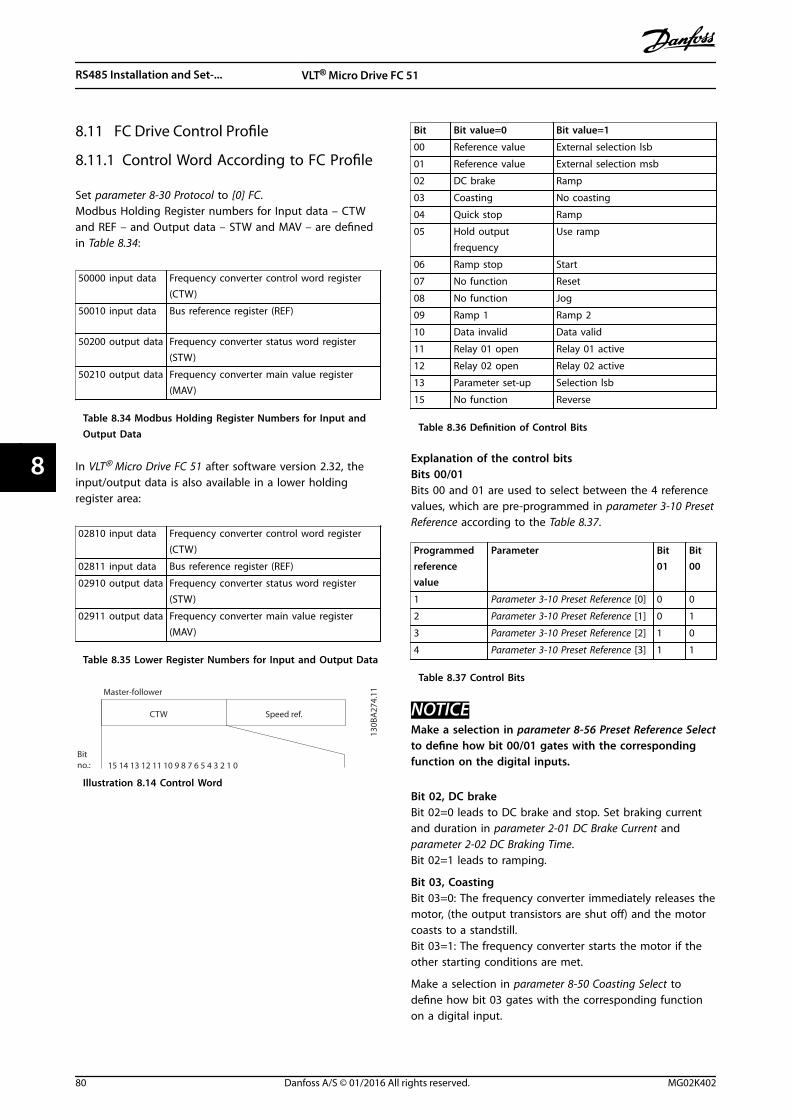
8.11 FC Drive Control Profile
8.11.1 Control Word According to FC Profile
Set parameter 8-30 Protocol to [0] FC.Modbus Holding Register numbers for Input data – CTWand REF – and Output data – STW and MAV – are definedin Table 8.34:
50000 input data Frequency converter control word register(CTW)
50010 input data Bus reference register (REF)
50200 output data Frequency converter status word register(STW)
50210 output data Frequency converter main value register(MAV)
Table 8.34 Modbus Holding Register Numbers for Input andOutput Data
In VLT® Micro Drive FC 51 after software version 2.32, theinput/output data is also available in a lower holdingregister area:
02810 input data Frequency converter control word register(CTW)
02811 input data Bus reference register (REF)
02910 output data Frequency converter status word register(STW)
02911 output data Frequency converter main value register(MAV)
Table 8.35 Lower Register Numbers for Input and Output Data
Speed ref.CTW
Master-follower
130B
A27
4.11
15 14 13 12 11 10 9 8 7 6 5 4 3 2 1 0Bitno.:
Illustration 8.14 Control Word
Bit Bit value=0 Bit value=1
00 Reference value External selection lsb
01 Reference value External selection msb
02 DC brake Ramp
03 Coasting No coasting
04 Quick stop Ramp
05 Hold outputfrequency
Use ramp
06 Ramp stop Start
07 No function Reset
08 No function Jog
09 Ramp 1 Ramp 2
10 Data invalid Data valid
11 Relay 01 open Relay 01 active
12 Relay 02 open Relay 02 active
13 Parameter set-up Selection lsb
15 No function Reverse
Table 8.36 Definition of Control Bits
Explanation of the control bitsBits 00/01Bits 00 and 01 are used to select between the 4 referencevalues, which are pre-programmed in parameter 3-10 PresetReference according to the Table 8.37.
Programmedreferencevalue
Parameter Bit01
Bit00
1 Parameter 3-10 Preset Reference [0] 0 0
2 Parameter 3-10 Preset Reference [1] 0 1
3 Parameter 3-10 Preset Reference [2] 1 0
4 Parameter 3-10 Preset Reference [3] 1 1
Table 8.37 Control Bits
NOTICEMake a selection in parameter 8-56 Preset Reference Selectto define how bit 00/01 gates with the correspondingfunction on the digital inputs.
Bit 02, DC brakeBit 02=0 leads to DC brake and stop. Set braking currentand duration in parameter 2-01 DC Brake Current andparameter 2-02 DC Braking Time.Bit 02=1 leads to ramping.
Bit 03, CoastingBit 03=0: The frequency converter immediately releases themotor, (the output transistors are shut off) and the motorcoasts to a standstill.Bit 03=1: The frequency converter starts the motor if theother starting conditions are met.
Make a selection in parameter 8-50 Coasting Select todefine how bit 03 gates with the corresponding functionon a digital input.
RS485 Installation and Set-... VLT® Micro Drive FC 51
80 Danfoss A/S © 01/2016 All rights reserved. MG02K402
88
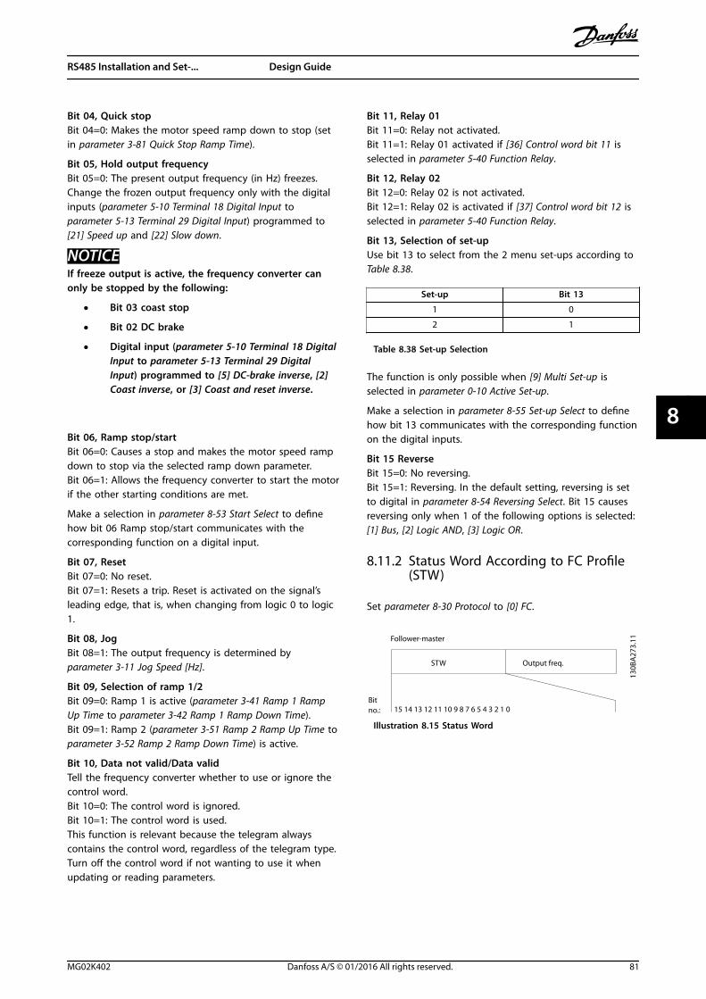
Bit 04, Quick stopBit 04=0: Makes the motor speed ramp down to stop (setin parameter 3-81 Quick Stop Ramp Time).
Bit 05, Hold output frequencyBit 05=0: The present output frequency (in Hz) freezes.Change the frozen output frequency only with the digitalinputs (parameter 5-10 Terminal 18 Digital Input toparameter 5-13 Terminal 29 Digital Input) programmed to[21] Speed up and [22] Slow down.
NOTICEIf freeze output is active, the frequency converter canonly be stopped by the following:
• Bit 03 coast stop
• Bit 02 DC brake
• Digital input (parameter 5-10 Terminal 18 DigitalInput to parameter 5-13 Terminal 29 DigitalInput) programmed to [5] DC-brake inverse, [2]Coast inverse, or [3] Coast and reset inverse.
Bit 06, Ramp stop/startBit 06=0: Causes a stop and makes the motor speed rampdown to stop via the selected ramp down parameter.Bit 06=1: Allows the frequency converter to start the motorif the other starting conditions are met.
Make a selection in parameter 8-53 Start Select to definehow bit 06 Ramp stop/start communicates with thecorresponding function on a digital input.
Bit 07, ResetBit 07=0: No reset.Bit 07=1: Resets a trip. Reset is activated on the signal’sleading edge, that is, when changing from logic 0 to logic1.
Bit 08, JogBit 08=1: The output frequency is determined byparameter 3-11 Jog Speed [Hz].
Bit 09, Selection of ramp 1/2Bit 09=0: Ramp 1 is active (parameter 3-41 Ramp 1 RampUp Time to parameter 3-42 Ramp 1 Ramp Down Time).Bit 09=1: Ramp 2 (parameter 3-51 Ramp 2 Ramp Up Time toparameter 3-52 Ramp 2 Ramp Down Time) is active.
Bit 10, Data not valid/Data validTell the frequency converter whether to use or ignore thecontrol word.Bit 10=0: The control word is ignored.Bit 10=1: The control word is used.This function is relevant because the telegram alwayscontains the control word, regardless of the telegram type.Turn off the control word if not wanting to use it whenupdating or reading parameters.
Bit 11, Relay 01Bit 11=0: Relay not activated.Bit 11=1: Relay 01 activated if [36] Control word bit 11 isselected in parameter 5-40 Function Relay.
Bit 12, Relay 02Bit 12=0: Relay 02 is not activated.Bit 12=1: Relay 02 is activated if [37] Control word bit 12 isselected in parameter 5-40 Function Relay.
Bit 13, Selection of set-upUse bit 13 to select from the 2 menu set-ups according toTable 8.38.
Set-up Bit 13
1 0
2 1
Table 8.38 Set-up Selection
The function is only possible when [9] Multi Set-up isselected in parameter 0-10 Active Set-up.
Make a selection in parameter 8-55 Set-up Select to definehow bit 13 communicates with the corresponding functionon the digital inputs.
Bit 15 ReverseBit 15=0: No reversing.Bit 15=1: Reversing. In the default setting, reversing is setto digital in parameter 8-54 Reversing Select. Bit 15 causesreversing only when 1 of the following options is selected:[1] Bus, [2] Logic AND, [3] Logic OR.
8.11.2 Status Word According to FC Profile(STW)
Set parameter 8-30 Protocol to [0] FC.
Output freq.STW
Bitno.:
Follower-master
15 14 13 12 11 10 9 8 7 6 5 4 3 2 1 0
130B
A27
3.11
Illustration 8.15 Status Word
RS485 Installation and Set-... Design Guide
MG02K402 Danfoss A/S © 01/2016 All rights reserved. 81
8 8
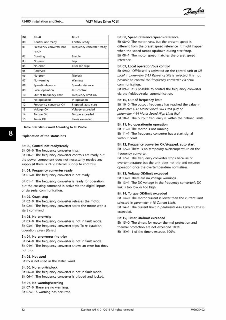
Bit Bit=0 Bit=1
00 Control not ready Control ready
01 Frequency converter notready
Frequency converter ready
02 Coasting Enable
03 No error Trip
04 No error Error (no trip)
05 Reserved –
06 No error Triplock
07 No warning Warning
08 Speed≠reference Speed=reference
09 Local operation Bus control
10 Out of frequency limit Frequency limit OK
11 No operation In operation
12 Frequency converter OK Stopped, auto start
13 Voltage OK Voltage exceeded
14 Torque OK Torque exceeded
15 Timer OK Timer exceeded
Table 8.39 Status Word According to FC Profile
Explanation of the status bits
Bit 00, Control not ready/readyBit 00=0: The frequency converter trips.Bit 00=1: The frequency converter controls are ready butthe power component does not necessarily receive anysupply (if there is 24 V external supply to controls).
Bit 01, Frequency converter readyBit 01=0: The frequency converter is not ready.
Bit 01=1: The frequency converter is ready for operation,but the coasting command is active via the digital inputsor via serial communication.
Bit 02, Coast stopBit 02=0: The frequency converter releases the motor.Bit 02=1: The frequency converter starts the motor with astart command.
Bit 03, No error/tripBit 03=0: The frequency converter is not in fault mode.Bit 03=1: The frequency converter trips. To re-establishoperation, press [Reset].
Bit 04, No error/error (no trip)Bit 04=0: The frequency converter is not in fault mode.Bit 04=1: The frequency converter shows an error but doesnot trip.
Bit 05, Not usedBit 05 is not used in the status word.
Bit 06, No error/triplockBit 06=0: The frequency converter is not in fault mode.Bit 06=1: The frequency converter is tripped and locked.
Bit 07, No warning/warningBit 07=0: There are no warnings.Bit 07=1: A warning has occurred.
Bit 08, Speed reference/speed=referenceBit 08=0: The motor runs, but the present speed isdifferent from the preset speed reference. It might happenwhen the speed ramps up/down during start/stop.Bit 08=1: The motor speed matches the preset speedreference.
Bit 09, Local operation/bus controlBit 09=0: [Off/Reset] is activated on the control unit or [2]Local in parameter 3-13 Reference Site is selected. It is notpossible to control the frequency converter via serialcommunication.Bit 09=1: It is possible to control the frequency convertervia the fieldbus/serial communication.
Bit 10, Out of frequency limitBit 10=0: The output frequency has reached the value inparameter 4-12 Motor Speed Low Limit [Hz] orparameter 4-14 Motor Speed High Limit [Hz].Bit 10=1: The output frequency is within the defined limits.
Bit 11, No operation/in operationBit 11=0: The motor is not running.Bit 11=1: The frequency converter has a start signalwithout coast.
Bit 12, Frequency converter OK/stopped, auto startBit 12=0: There is no temporary overtemperature on thefrequency converter.Bit 12=1: The frequency converter stops because ofovertemperature but the unit does not trip and resumesoperation once the overtemperature normalizes.
Bit 13, Voltage OK/limit exceededBit 13=0: There are no voltage warnings.Bit 13=1: The DC voltage in the frequency converter’s DClink is too low or too high.
Bit 14, Torque OK/limit exceededBit 14=0: The motor current is lower than the current limitselected in parameter 4-18 Current Limit.Bit 14=1: The current limit in parameter 4-18 Current Limit isexceeded.
Bit 15, Timer OK/limit exceededBit 15=0: The timers for motor thermal protection andthermal protection are not exceeded 100%.Bit 15=1: 1 of the timers exceeds 100%.
RS485 Installation and Set-... VLT® Micro Drive FC 51
82 Danfoss A/S © 01/2016 All rights reserved. MG02K402
88
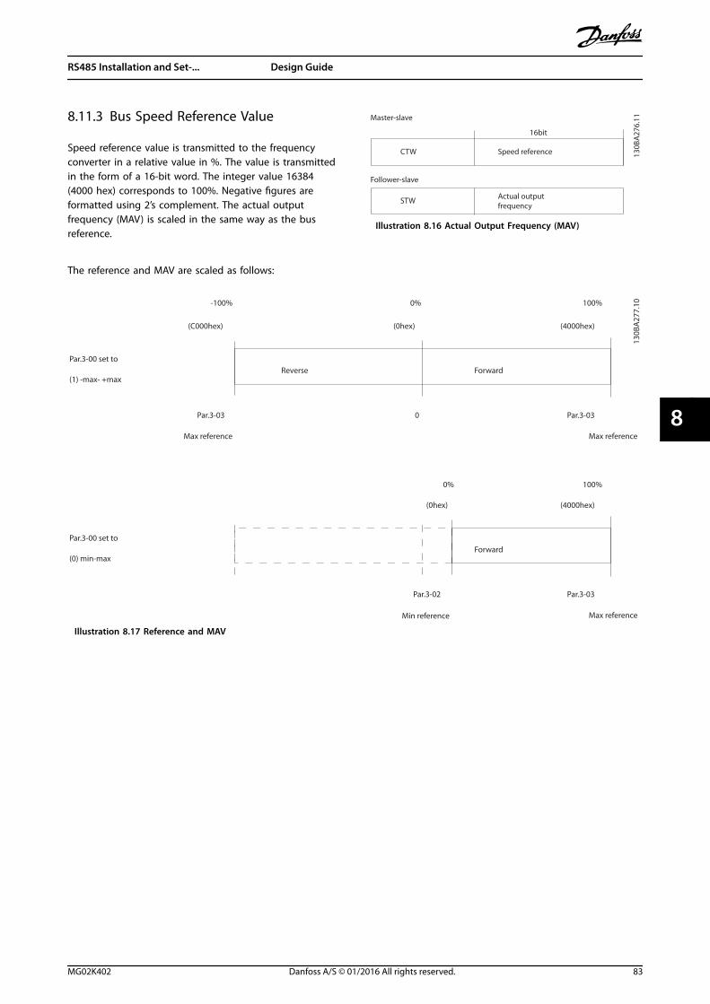
8.11.3 Bus Speed Reference Value
Speed reference value is transmitted to the frequencyconverter in a relative value in %. The value is transmittedin the form of a 16-bit word. The integer value 16384(4000 hex) corresponds to 100%. Negative figures areformatted using 2’s complement. The actual outputfrequency (MAV) is scaled in the same way as the busreference.
Actual outputfrequency
STW
Follower-slave
Speed referenceCTW
Master-slave
16bit
130B
A27
6.11
Illustration 8.16 Actual Output Frequency (MAV)
The reference and MAV are scaled as follows:
Reverse ForwardPar.3-00 set to
(1) -max- +max
Max reference Max reference
Par.3-00 set to
(0) min-max
Max reference
Forward
Min reference
100%
(4000hex)
-100%
(C000hex)
0%
(0hex)
Par.3-03 0 Par.3-03
Par.3-03
(4000hex)(0hex)
0% 100%
Par.3-02
130B
A27
7.10
Illustration 8.17 Reference and MAV
RS485 Installation and Set-... Design Guide
MG02K402 Danfoss A/S © 01/2016 All rights reserved. 83
8 8
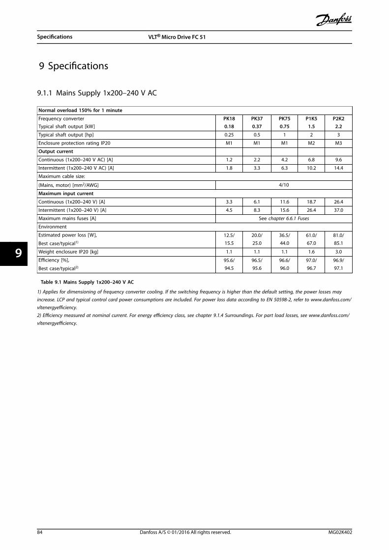
9 Specifications
9.1.1 Mains Supply 1x200–240 V AC
Normal overload 150% for 1 minute
Frequency converterTypical shaft output [kW]
PK180.18
PK370.37
PK750.75
P1K51.5
P2K22.2
Typical shaft output [hp] 0.25 0.5 1 2 3
Enclosure protection rating IP20 M1 M1 M1 M2 M3
Output current
Continuous (1x200–240 V AC) [A] 1.2 2.2 4.2 6.8 9.6
Intermittent (1x200–240 V AC) [A] 1.8 3.3 6.3 10.2 14.4
Maximum cable size:
(Mains, motor) [mm2/AWG] 4/10
Maximum input current
Continuous (1x200–240 V) [A] 3.3 6.1 11.6 18.7 26.4
Intermittent (1x200–240 V) [A] 4.5 8.3 15.6 26.4 37.0
Maximum mains fuses [A] See chapter 6.6.1 Fuses
Environment
Estimated power loss [W],
Best case/typical1)
12.5/15.5
20.0/25.0
36.5/44.0
61.0/67.0
81.0/85.1
Weight enclosure IP20 [kg] 1.1 1.1 1.1 1.6 3.0
Efficiency [%],
Best case/typical2)
95.6/94.5
96.5/95.6
96.6/96.0
97.0/96.7
96.9/97.1
Table 9.1 Mains Supply 1x200–240 V AC
1) Applies for dimensioning of frequency converter cooling. If the switching frequency is higher than the default setting, the power losses mayincrease. LCP and typical control card power consumptions are included. For power loss data according to EN 50598-2, refer to www.danfoss.com/vltenergyefficiency.2) Efficiency measured at nominal current. For energy efficiency class, see chapter 9.1.4 Surroundings. For part load losses, see www.danfoss.com/vltenergyefficiency.
Specifications VLT® Micro Drive FC 51
84 Danfoss A/S © 01/2016 All rights reserved. MG02K402
99
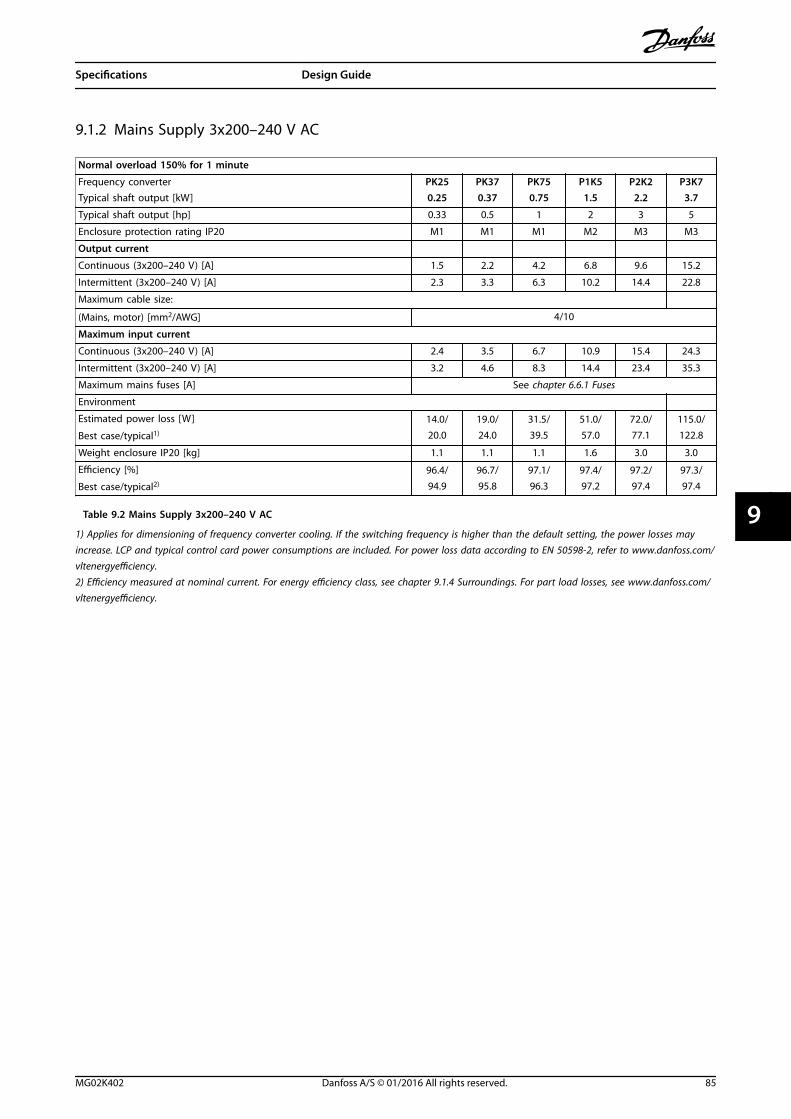
9.1.2 Mains Supply 3x200–240 V AC
Normal overload 150% for 1 minute
Frequency converterTypical shaft output [kW]
PK250.25
PK370.37
PK750.75
P1K51.5
P2K22.2
P3K73.7
Typical shaft output [hp] 0.33 0.5 1 2 3 5
Enclosure protection rating IP20 M1 M1 M1 M2 M3 M3
Output current
Continuous (3x200–240 V) [A] 1.5 2.2 4.2 6.8 9.6 15.2
Intermittent (3x200–240 V) [A] 2.3 3.3 6.3 10.2 14.4 22.8
Maximum cable size:
(Mains, motor) [mm2/AWG] 4/10
Maximum input current
Continuous (3x200–240 V) [A] 2.4 3.5 6.7 10.9 15.4 24.3
Intermittent (3x200–240 V) [A] 3.2 4.6 8.3 14.4 23.4 35.3
Maximum mains fuses [A] See chapter 6.6.1 Fuses
Environment
Estimated power loss [W]
Best case/typical1)
14.0/20.0
19.0/24.0
31.5/39.5
51.0/57.0
72.0/77.1
115.0/122.8
Weight enclosure IP20 [kg] 1.1 1.1 1.1 1.6 3.0 3.0
Efficiency [%]
Best case/typical2)
96.4/94.9
96.7/95.8
97.1/96.3
97.4/97.2
97.2/97.4
97.3/97.4
Table 9.2 Mains Supply 3x200–240 V AC
1) Applies for dimensioning of frequency converter cooling. If the switching frequency is higher than the default setting, the power losses mayincrease. LCP and typical control card power consumptions are included. For power loss data according to EN 50598-2, refer to www.danfoss.com/vltenergyefficiency.2) Efficiency measured at nominal current. For energy efficiency class, see chapter 9.1.4 Surroundings. For part load losses, see www.danfoss.com/vltenergyefficiency.
Specifications Design Guide
MG02K402 Danfoss A/S © 01/2016 All rights reserved. 85
9 9
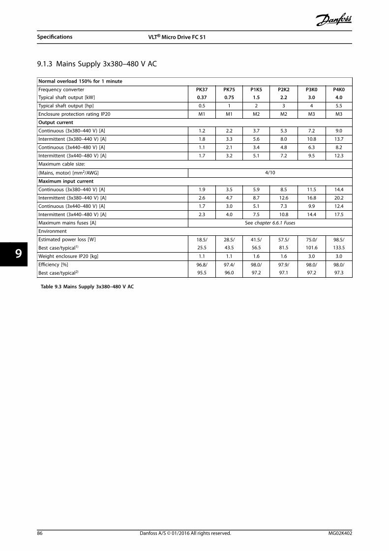
9.1.3 Mains Supply 3x380–480 V AC
Normal overload 150% for 1 minute
Frequency converterTypical shaft output [kW]
PK370.37
PK750.75
P1K51.5
P2K22.2
P3K03.0
P4K04.0
Typical shaft output [hp] 0.5 1 2 3 4 5.5
Enclosure protection rating IP20 M1 M1 M2 M2 M3 M3
Output current
Continuous (3x380–440 V) [A] 1.2 2.2 3.7 5.3 7.2 9.0
Intermittent (3x380–440 V) [A] 1.8 3.3 5.6 8.0 10.8 13.7
Continuous (3x440–480 V) [A] 1.1 2.1 3.4 4.8 6.3 8.2
Intermittent (3x440–480 V) [A] 1.7 3.2 5.1 7.2 9.5 12.3
Maximum cable size:
(Mains, motor) [mm2/AWG] 4/10
Maximum input current
Continuous (3x380–440 V) [A] 1.9 3.5 5.9 8.5 11.5 14.4
Intermittent (3x380–440 V) [A] 2.6 4.7 8.7 12.6 16.8 20.2
Continuous (3x440–480 V) [A] 1.7 3.0 5.1 7.3 9.9 12.4
Intermittent (3x440–480 V) [A] 2.3 4.0 7.5 10.8 14.4 17.5
Maximum mains fuses [A] See chapter 6.6.1 Fuses
Environment
Estimated power loss [W]
Best case/typical1)
18.5/25.5
28.5/43.5
41.5/56.5
57.5/81.5
75.0/101.6
98.5/133.5
Weight enclosure IP20 [kg] 1.1 1.1 1.6 1.6 3.0 3.0
Efficiency [%]
Best case/typical2)
96.8/95.5
97.4/96.0
98.0/97.2
97.9/97.1
98.0/97.2
98.0/97.3
Table 9.3 Mains Supply 3x380–480 V AC
Specifications VLT® Micro Drive FC 51
86 Danfoss A/S © 01/2016 All rights reserved. MG02K402
99
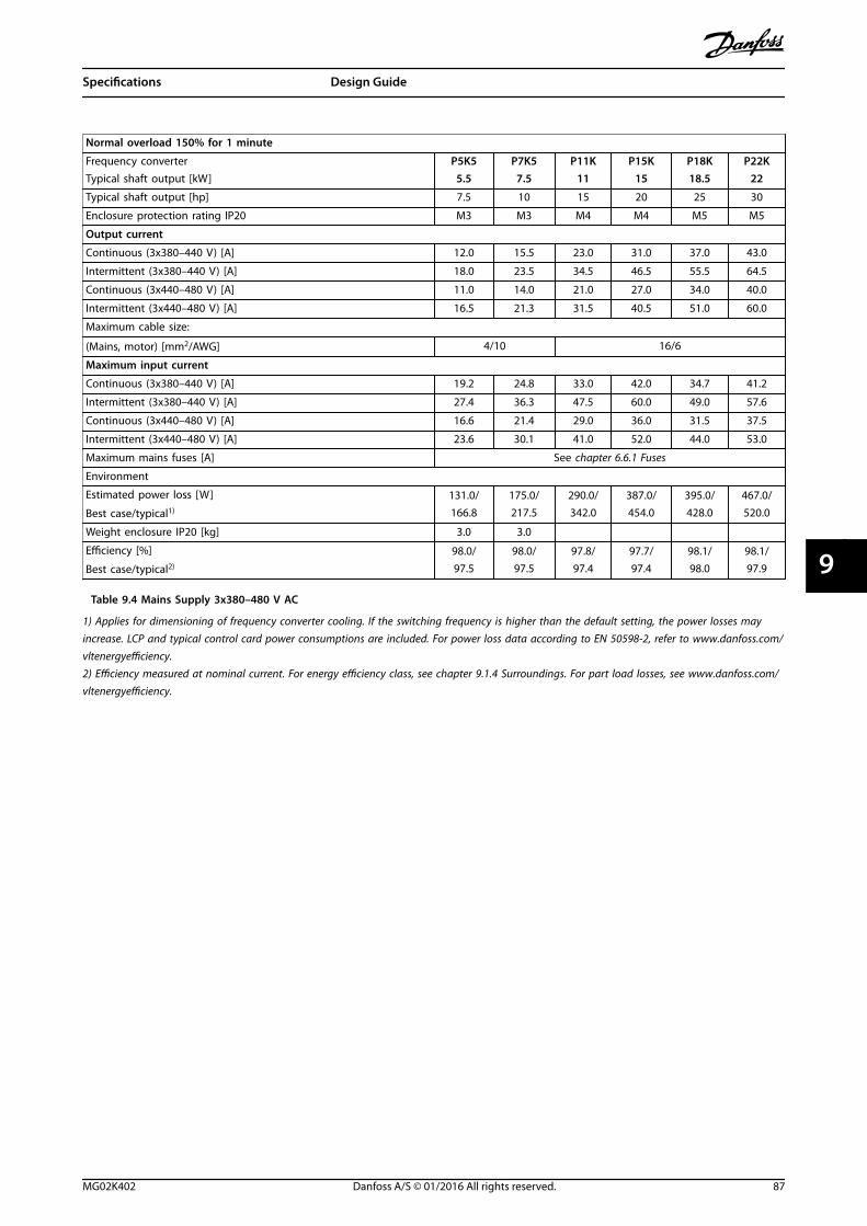
Normal overload 150% for 1 minute
Frequency converterTypical shaft output [kW]
P5K55.5
P7K57.5
P11K11
P15K15
P18K18.5
P22K22
Typical shaft output [hp] 7.5 10 15 20 25 30
Enclosure protection rating IP20 M3 M3 M4 M4 M5 M5
Output current
Continuous (3x380–440 V) [A] 12.0 15.5 23.0 31.0 37.0 43.0
Intermittent (3x380–440 V) [A] 18.0 23.5 34.5 46.5 55.5 64.5
Continuous (3x440–480 V) [A] 11.0 14.0 21.0 27.0 34.0 40.0
Intermittent (3x440–480 V) [A] 16.5 21.3 31.5 40.5 51.0 60.0
Maximum cable size:
(Mains, motor) [mm2/AWG] 4/10 16/6
Maximum input current
Continuous (3x380–440 V) [A] 19.2 24.8 33.0 42.0 34.7 41.2
Intermittent (3x380–440 V) [A] 27.4 36.3 47.5 60.0 49.0 57.6
Continuous (3x440–480 V) [A] 16.6 21.4 29.0 36.0 31.5 37.5
Intermittent (3x440–480 V) [A] 23.6 30.1 41.0 52.0 44.0 53.0
Maximum mains fuses [A] See chapter 6.6.1 Fuses
Environment
Estimated power loss [W]
Best case/typical1)
131.0/166.8
175.0/217.5
290.0/342.0
387.0/454.0
395.0/428.0
467.0/520.0
Weight enclosure IP20 [kg] 3.0 3.0
Efficiency [%]
Best case/typical2)
98.0/97.5
98.0/97.5
97.8/97.4
97.7/97.4
98.1/98.0
98.1/97.9
Table 9.4 Mains Supply 3x380–480 V AC
1) Applies for dimensioning of frequency converter cooling. If the switching frequency is higher than the default setting, the power losses mayincrease. LCP and typical control card power consumptions are included. For power loss data according to EN 50598-2, refer to www.danfoss.com/vltenergyefficiency.2) Efficiency measured at nominal current. For energy efficiency class, see chapter 9.1.4 Surroundings. For part load losses, see www.danfoss.com/vltenergyefficiency.
Specifications Design Guide
MG02K402 Danfoss A/S © 01/2016 All rights reserved. 87
9 9
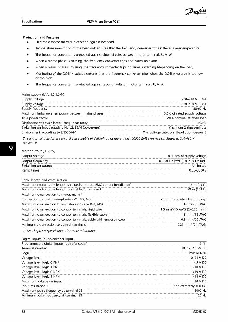
Protection and Features• Electronic motor thermal protection against overload.
• Temperature monitoring of the heat sink ensures that the frequency converter trips if there is overtemperature.
• The frequency converter is protected against short circuits between motor terminals U, V, W.
• When a motor phase is missing, the frequency converter trips and issues an alarm.
• When a mains phase is missing, the frequency converter trips or issues a warning (depending on the load).
• Monitoring of the DC-link voltage ensures that the frequency converter trips when the DC-link voltage is too lowor too high.
• The frequency converter is protected against ground faults on motor terminals U, V, W.
Mains supply (L1/L, L2, L3/N)Supply voltage 200–240 V ±10%Supply voltage 380–480 V ±10%Supply frequency 50/60 HzMaximum imbalance temporary between mains phases 3.0% of rated supply voltageTrue power factor ≥0.4 nominal at rated loadDisplacement power factor (cosφ) near unity (>0.98)Switching on input supply L1/L, L2, L3/N (power-ups) Maximum 2 times/minuteEnvironment according to EN60664-1 Overvoltage category III/pollution degree 2
The unit is suitable for use on a circuit capable of delivering not more than 100000 RMS symmetrical Amperes, 240/480 Vmaximum.
Motor output (U, V, W)Output voltage 0–100% of supply voltageOutput frequency 0–200 Hz (VVC+), 0–400 Hz (u/f )Switching on output UnlimitedRamp times 0.05–3600 s
Cable length and cross-sectionMaximum motor cable length, shielded/armored (EMC-correct installation) 15 m (49 ft)Maximum motor cable length, unshielded/unarmored 50 m (164 ft)Maximum cross-section to motor, mains1)
Connection to load sharing/brake (M1, M2, M3) 6.3 mm insulated Faston plugsMaximum cross-section to load sharing/brake (M4, M5) 16 mm2/6 AWGMaximum cross-section to control terminals, rigid wire 1.5 mm2/16 AWG (2x0.75 mm2)Maximum cross-section to control terminals, flexible cable 1 mm2/18 AWGMaximum cross-section to control terminals, cable with enclosed core 0.5 mm2/20 AWGMinimum cross-section to control terminals 0.25 mm2 (24 AWG)
1) See chapter 9 Specifications for more information.
Digital inputs (pulse/encoder inputs)Programmable digital inputs (pulse/encoder) 5 (1)Terminal number 18, 19, 27, 29, 33Logic PNP or NPNVoltage level 0–24 V DCVoltage level, logic 0 PNP <5 V DCVoltage level, logic 1 PNP >10 V DCVoltage level, logic 0 NPN >19 V DCVoltage level, logic 1 NPN <14 V DCMaximum voltage on input 28 V DCInput resistance, Ri Approximately 4000 ΩMaximum pulse frequency at terminal 33 5000 HzMinimum pulse frequency at terminal 33 20 Hz
Specifications VLT® Micro Drive FC 51
88 Danfoss A/S © 01/2016 All rights reserved. MG02K402
99
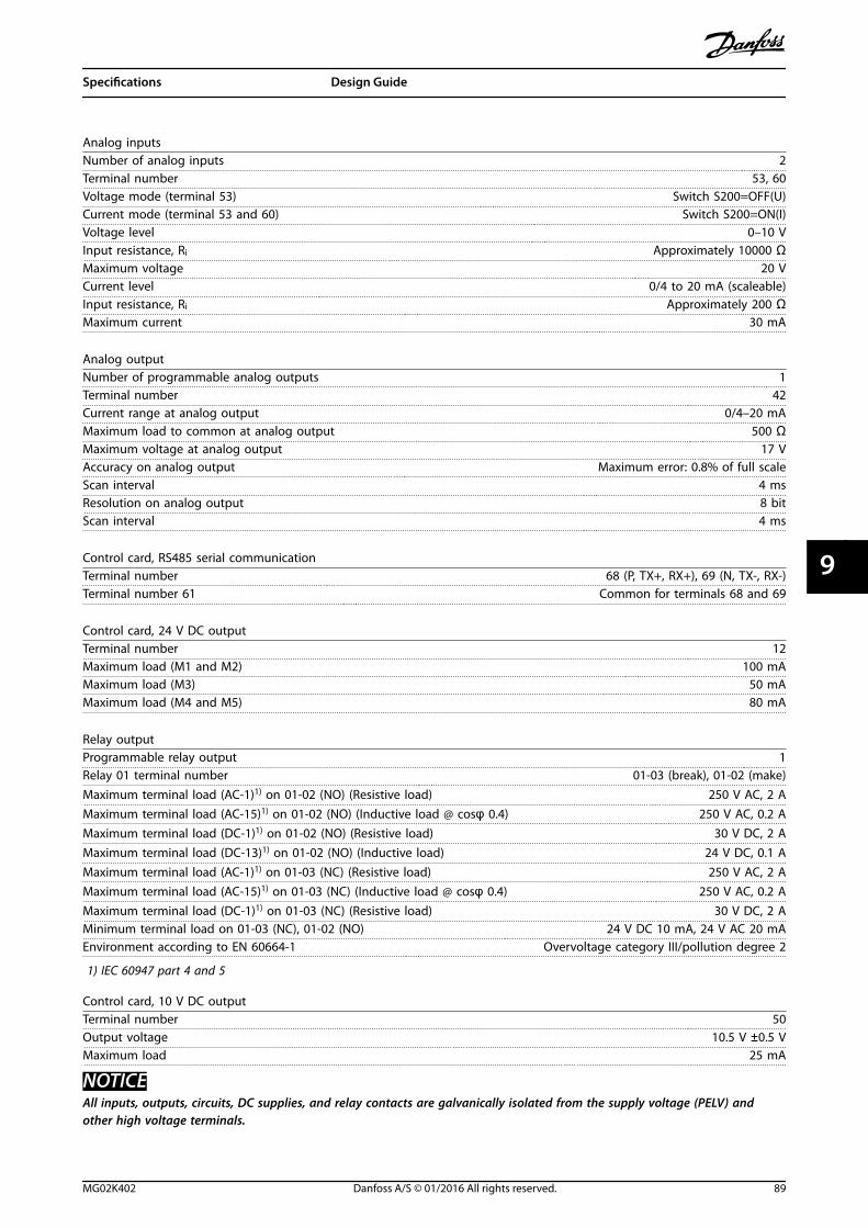
Analog inputsNumber of analog inputs 2Terminal number 53, 60Voltage mode (terminal 53) Switch S200=OFF(U)Current mode (terminal 53 and 60) Switch S200=ON(I)Voltage level 0–10 VInput resistance, Ri Approximately 10000 ΩMaximum voltage 20 VCurrent level 0/4 to 20 mA (scaleable)Input resistance, Ri Approximately 200 ΩMaximum current 30 mA
Analog outputNumber of programmable analog outputs 1Terminal number 42Current range at analog output 0/4–20 mAMaximum load to common at analog output 500 ΩMaximum voltage at analog output 17 VAccuracy on analog output Maximum error: 0.8% of full scaleScan interval 4 msResolution on analog output 8 bitScan interval 4 ms
Control card, RS485 serial communicationTerminal number 68 (P, TX+, RX+), 69 (N, TX-, RX-)Terminal number 61 Common for terminals 68 and 69
Control card, 24 V DC outputTerminal number 12Maximum load (M1 and M2) 100 mAMaximum load (M3) 50 mAMaximum load (M4 and M5) 80 mA
Relay outputProgrammable relay output 1Relay 01 terminal number 01-03 (break), 01-02 (make)Maximum terminal load (AC-1)1) on 01-02 (NO) (Resistive load) 250 V AC, 2 AMaximum terminal load (AC-15)1) on 01-02 (NO) (Inductive load @ cosφ 0.4) 250 V AC, 0.2 AMaximum terminal load (DC-1)1) on 01-02 (NO) (Resistive load) 30 V DC, 2 AMaximum terminal load (DC-13)1) on 01-02 (NO) (Inductive load) 24 V DC, 0.1 AMaximum terminal load (AC-1)1) on 01-03 (NC) (Resistive load) 250 V AC, 2 AMaximum terminal load (AC-15)1) on 01-03 (NC) (Inductive load @ cosφ 0.4) 250 V AC, 0.2 AMaximum terminal load (DC-1)1) on 01-03 (NC) (Resistive load) 30 V DC, 2 AMinimum terminal load on 01-03 (NC), 01-02 (NO) 24 V DC 10 mA, 24 V AC 20 mAEnvironment according to EN 60664-1 Overvoltage category III/pollution degree 2
1) IEC 60947 part 4 and 5
Control card, 10 V DC outputTerminal number 50Output voltage 10.5 V ±0.5 VMaximum load 25 mA
NOTICEAll inputs, outputs, circuits, DC supplies, and relay contacts are galvanically isolated from the supply voltage (PELV) andother high voltage terminals.
Specifications Design Guide
MG02K402 Danfoss A/S © 01/2016 All rights reserved. 89
9 9
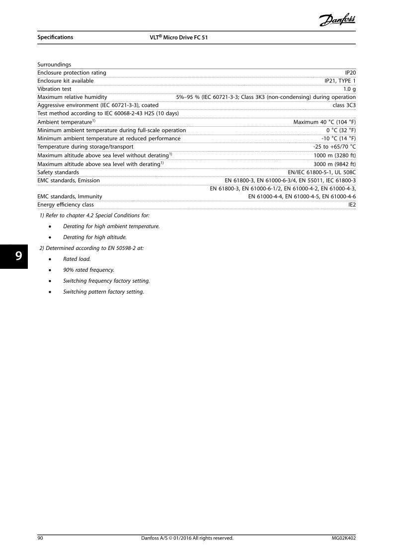
SurroundingsEnclosure protection rating IP20Enclosure kit available IP21, TYPE 1Vibration test 1.0 gMaximum relative humidity 5%–95 % (IEC 60721-3-3; Class 3K3 (non-condensing) during operationAggressive environment (IEC 60721-3-3), coated class 3C3Test method according to IEC 60068-2-43 H2S (10 days)Ambient temperature1) Maximum 40 °C (104 °F)Minimum ambient temperature during full-scale operation 0 °C (32 °F)Minimum ambient temperature at reduced performance -10 °C (14 °F)Temperature during storage/transport -25 to +65/70 °CMaximum altitude above sea level without derating1) 1000 m (3280 ft)Maximum altitude above sea level with derating1) 3000 m (9842 ft)Safety standards EN/IEC 61800-5-1, UL 508CEMC standards, Emission EN 61800-3, EN 61000-6-3/4, EN 55011, IEC 61800-3
EMC standards, ImmunityEN 61800-3, EN 61000-6-1/2, EN 61000-4-2, EN 61000-4-3,
EN 61000-4-4, EN 61000-4-5, EN 61000-4-6Energy efficiency class IE2
1) Refer to chapter 4.2 Special Conditions for:
• Derating for high ambient temperature.
• Derating for high altitude.
2) Determined according to EN 50598-2 at:
• Rated load.
• 90% rated frequency.
• Switching frequency factory setting.
• Switching pattern factory setting.
Specifications VLT® Micro Drive FC 51
90 Danfoss A/S © 01/2016 All rights reserved. MG02K402
99
Index
AAbbreviations........................................................................................... 5
Active set-up.......................................................................................... 57
Aggressive environment.................................................................... 11
Air humidity............................................................................................ 11
Aluminum conductors........................................................................ 46
Ambient temperature......................................................................... 90
Analog input................................................................................. 6, 7, 89
Automatic adaptations to ensure performance........................ 37
BBetter control......................................................................................... 15
Break-away torque.................................................................................. 6
Building management system, BMS.............................................. 13
Bus termination..................................................................................... 52
CCable
clamp.................................................................................................... 49length and cross-section........................................................ 46, 88Control cable..................................................................................... 51Equalizing cable............................................................................... 49Grounding, shielded/armored control cables....................... 49Motor cable................................................................................. 21, 46Shielding of cables.......................................................................... 46
CE conformity and labeling.............................................................. 10
Clearance................................................................................................. 42
Coasting........................................................................................ 6, 80, 82
Comparison, energy saving.............................................................. 13
Control structure closed loop.......................................................... 19
Control structure open loop............................................................. 18
Control terminals.................................................................................. 52
Control word.......................................................................................... 80
Controlling fan....................................................................................... 12
Controlling pump................................................................................. 12
Covered, what is.................................................................................... 11
Currentloops..................................................................................................... 21Leakage current................................................................................ 21Rated current..................................................................................... 22
DData type, supported.......................................................................... 70
DC brake.................................................................................................. 80
Decoupling plate.................................................................................. 28
Definition............................................................................................ 6, 22
Deratingfor low air pressure.......................................................................... 37
Digital input............................................................................................ 88
Discharge time......................................................................................... 9
Display...................................................................................................... 57
Disposal.................................................................................................... 10
Drive configurator................................................................................ 38
EEdit set-up............................................................................................... 57
Electrical installation.................................................................... 46, 51
EMCEMC................................................................................................ 21, 22Directive (89/336/EEC)............................................................ 10, 11plan....................................................................................................... 22precautions........................................................................................ 66test results (emission)..................................................................... 22EMC-correct electrical installation............................................. 46Emission requirements........................................................... 21, 22Emissions............................................................................................ 21Immunity requirements................................................................ 21Use of EMC-correct cables............................................................ 48
Energy efficiency.............................................................. 84, 85, 86, 87
Energy efficiency class........................................................................ 90
Energy saving.................................................................................. 12, 14
Energy saving example...................................................................... 13
EnvironmentIndustrial............................................................................................. 22Residential.......................................................................................... 22
ETR............................................................................................................. 54
Extreme running condition............................................................... 24
FFC profile
FC profile............................................................................................. 80FC with Modbus RTU...................................................................... 67Protocol overview............................................................................ 66
Final set-up and test............................................................................ 52
Freeze output........................................................................................... 6
Frequency converter hardware set-up......................................... 65
Function code........................................................................................ 75
GGalvanic isolation................................................................................. 23
Ground leakage current.............................................................. 24, 56
Ground leakage protection.............................................................. 21
Grounding............................................................................................... 49
Index Design Guide
MG02K402 Danfoss A/S © 01/2016 All rights reserved. 91
HHarmonics
distortion............................................................................................ 21emission requirements.................................................................. 23
High voltage............................................................................................. 9
High-voltage test.................................................................................. 56
Hold output frequency....................................................................... 81
IImmunity requirement....................................................................... 23
IND............................................................................................................. 70
Index (IND).............................................................................................. 70
Indicator lights....................................................................................... 58
Initialize the frequency converter.................................................. 63
Intermediate circuit...................................................................... 24, 37
IP21/TYPE 1 enclosure kit.................................................................. 28
JJog......................................................................................................... 6, 81
LLCP............................................................................................. 6, 7, 18, 26
LCP 11....................................................................................................... 57
LCP 12....................................................................................................... 57
LCP copy.................................................................................................. 63
Leakage current...................................................................... 10, 24, 56
Load sharing............................................................................................. 9
Local (Hand On) and remote (Auto On) control........................ 18
Low Voltage Directive (73/23/EEC)................................................ 10
MMachinery directive (98/37/EEC).................................................... 10
Main Menu................................................................................ 26, 58, 63
Mains drop-out...................................................................................... 24
Mains supply (L1/L, L2, L3/N)........................................................... 88
Mains supply 1x200–240 V AC......................................................... 84
Mains supply 3x200–240 V AC......................................................... 85
Mains supply 3x380–480 V AC......................................................... 86
Maximum reference...................................................................... 60, 61
Minimum reference...................................................................... 60, 61
Modbus communication................................................................... 66
Modbus exception code.................................................................... 76
Modbus RTU........................................................................................... 72
Modbus RTU overview....................................................................... 71
Moment of inertia................................................................................ 24
MotorAutomatic motor tuning........................................................ 53, 59connection......................................................................................... 45current.................................................................................................. 59direction.............................................................................................. 58frequency............................................................................................ 59nameplate data................................................................................. 52nominal speed.................................................................................. 59overload protection........................................................................ 88phase.................................................................................................... 24power................................................................................................... 59protection........................................................................................... 54thermal protection................................................................... 24, 82voltage................................................................................................. 59Motor-generated overvoltage.................................................... 24Parallel connection of motors..................................................... 54Rated motor speed............................................................................ 6Short circuit (motor phase-phase)............................................. 24Unintended motor rotation......................................................... 10
NNameplate data..................................................................................... 52
Navigation keys.............................................................................. 26, 58
Network configuration....................................................................... 72
Network connection............................................................................ 65
OOperation keys............................................................................... 26, 58
Options and accessories.................................................................... 26
Overcurrent protection...................................................................... 44
PParameter number............................................................................... 57
Payback period...................................................................................... 14
PC software tools.................................................................................. 55
PELV, protective extra low voltage................................................. 23
PLC............................................................................................................. 49
Power circuit overview....................................................................... 50
Power factor.............................................................................................. 8
Protection........................................................................... 11, 23, 44, 88
Public supply network........................................................................ 23
QQuick menu.............................................................................. 26, 58, 59
Quick transfer......................................................................................... 63
RRamp 1 ramp-down time.................................................................. 60
Ramp 1 ramp-up time......................................................................... 60
RCD............................................................................................................... 7
Read holding registers (03 hex)....................................................... 78
Index VLT® Micro Drive FC 51
92 Danfoss A/S © 01/2016 All rights reserved. MG02K402
Read-out and programming of indexed parameters.............. 63
Readout mode....................................................................................... 58
Reference handling.............................................................................. 20
References................................................................................................. 6
Relay output........................................................................................... 89
Residual current device...................................................................... 49
RS485RS485............................................................................................. 65, 67bus connection................................................................................. 55installation and set-up................................................................... 65
SS200 Switches 1–4................................................................................ 52
Safety........................................................................................................ 10
Safety ground connection................................................................. 56
Save drive settings............................................................................... 55
Save frequency converter settings................................................. 55
Serial communication.................................................................. 49, 58
Serial communication port.................................................................. 6
Set speed limit and ramp time........................................................ 53
Set-up number...................................................................................... 57
Shock......................................................................................................... 12
Soft starter............................................................................................... 15
Software version...................................................................................... 5
Star/Delta starter.................................................................................. 15
Status........................................................................................................ 26
Status menu........................................................................................... 58
Status word............................................................................................. 81
Successful AMT...................................................................................... 53
Switches................................................................................................... 52
Switching frequency........................................................................... 46
Switching on the output.................................................................... 24
TTelegram length (LGE)......................................................................... 68
Thermistor................................................................................................. 7
Type 1 (NEMA)........................................................................................ 28
Type code string.................................................................................... 38
UUL compliance....................................................................................... 44
Unintended start..................................................................................... 9
Unit............................................................................................................ 57
Unsuccessful AMT................................................................................ 53
VValue.......................................................................................................... 57
Variable control, flow and pressure................................................ 15
Varying flow (1 year)............................................................................ 14
Vibration.................................................................................................. 12
Voltage level........................................................................................... 88
VVC............................................................................................................... 8
WWindmilling............................................................................................ 10
Index Design Guide
MG02K402 Danfoss A/S © 01/2016 All rights reserved. 93

Danfoss can accept no responsibility for possible errors in catalogues, brochures and other printed material. Danfoss reserves the right to alter its products without notice. This also applies toproducts already on order provided that such alterations can be made without subsequential changes being necessary in specifications already agreed. All trademarks in this material are propertyof the respective companies. Danfoss and the Danfoss logotype are trademarks of Danfoss A/S. All rights reserved.
Danfoss A/SUlsnaes 1DK-6300 Graastenvlt-drives.danfoss.com
*MG02K402*132R0059 MG02K402 01/2016