Embed Size (px)
Citation preview

yp&yT
VL:E665Urr
SHARP SERVICE MANUAL SYBASJL-E630U
LIQUID CRYSTAL CAMCORDER q NTSC
VL-E630U/T VL=E680U
MODELS VL-E685U/T In the interests of user-safety (Required by safety regula- tions in some countries) the set should be restored to its original condition and only parts identical to those specified be used.
CONTENTS Page
2. SPECIFICATIONS .............................................................................................................................. 2 4. DISASSEMBLY OF THE SET ............................................................................................................. 3 5. MECHANISM ADJUSTMENT.. ........................................................................................................... 4 6. ADJUSTMENT OF VCR.. .................................................................................................................... 5 8. SCHEMATIC DIAGRAMS.. ................................................................................................................ 8
11 .REPLACEMENT PARTS LIST .......................................................................................................... 29 12.PACKlNG OF THE SET .................................................................................................................... 35
SHARP CORPORATlON This document has been published to be used for after sales service only. The contents are subject to change without notice.

~p3o~fr
VL:E685Un
2. SPECIFICATIONS
Signal System: Recording System:
Cassette: Recording/Playback Time:
Tape Speed: Pickup Device:
Lens: Lens Filter Diameter:
Monitor: Microphone:
Color Temperature Compensation Minimum Illumination:
Video Output Level: Audio Output Level:
Speaker Output: Power Requirement: Power Consumption:
Operating Temperature: Operating Humidity:
Storage Temperature: Dimensions (approx.):
Weight (approx.):
NTSC standard 2 rotary heads, helical scanning system 8 mm video tape, MP type 120 minutes (P6- 120) 14.345 mm/second l/4” (6.4mm, effective size: 4.5 mm) CCD image sensor with approx. 270,000 pixels including optical black 16 x power zoom lens (F1.4, f=4.0-64.0 mm) and full-range auto focus 46 mm 3” (7.5 cm)-full-color LCD screen (TFT active matrix) Electret monaural microphone Auto white balance 0.8 lux (5 lux measured by EIA standard) (with gain-up, F1.4) 1 .O Vp-p 75-ohm unbalanced -8 dBs, impedance less than 2.2 kohms 200 mW DC 3.6V E630U:4.8W (during camera recording in full auto mode with zoom motor off, and backlight in normal mode) E680U/E685U:4.9W (during camera recording in full auto mode with zoom motor off, Extend Zoom, DIS and Snapshot functions off, and backlight in normal mode) 0°C to + 40°C (32°F to 104°F) 30% to 80% -20°C to +6O”C (-4°F to 140°F) 7 5/32” (W) x 4 g/$ (H) x 3 7/~” (D) [182 mm (W) x 109 mm (H) x 99 mm (D)] 1.52lbs (690g) (without battery pack, lithium battery, video cassette, and lens cap)
AC Adapter/Battery Charger Battery Pack BT-H22 UADP-0274TAZZ(VL-E63OU/680U/685U)
UADP-0275TAZZ(VL-E63OT/685T) DC Output: 3.6V
Dimensions (approx.): 2 l/s” (W) x 3/4” (H) x 2 7/32” (D)
Power Requirement: DC Output:
Power Consumption: Dimensions (approx.):
AC 11 O-240 V, 50160 Hz 4.5 v 16W 2 31/32” (W) x 2” (H) x 5 5/16” (D) r/5mm(W)x51 mm(H)x 135 mm (D)] 0.65 Ibs (295 g)
k$,mmm(OJ x 19 mm O-4 x
Weight (approx.): 0.30 Ibs (136 g)
Weight (approx.):
Specifications are subject to change without notice.
SERVICE INFORMATION (For the U.S.) For the location of the nearest Sharp Authorized Service, or to obtain product literature, accessories, supplies or customer assistance, please call l -800-BE SHARP (l-800-237-4277) or visit SHARP’s web site (http://www.sharp-usa.com)

4. DISASSEMBLY OFTHE SET 4-2. Disassembly of the VCR main body 1. Removal of the VCR lid shaft (l)Remove one screw ((j)LX-HZ0063TAFC).
4-3. REPLACEMENT OF CCD SENSOR 4-3-l. BEFORE REPLACEMENT 1) The CCD image sensor is more sensitive to electrostatic breakage than C-MOS LSI. Therefore sufficient means to
prevent electrostatic damage must be taken when it is replaced. l Ground the soldering iron. l Ground also the human body, using the wrist strap(through an 1 Mohm resistor). l Until the CCDsensor is mounted on the PWB, fit it to the conductive sponge, and short-circuit the foot lead. 2) Take utmost care so that the surface glass of CCD sensor and optical filter are not contaminated and damaged. If any
contamination is found, for example fingerprint, wipe it off with silicon paper or clean chamois skin. 3) When replacing the CCD sensor, use the antistaic grounded soldring iron, and perform quickly soldering.
Index Mark 1 7
SHARP
LZ2413H5
4-4. INITIAL SE-KING OF EzPROM IC 4-4-2. IC702 (E*PROM) When the IC702 has been replaced, make the following settings and adjustments.
Remove the backup battery (CR2029 Turn power switch to CAMERA Setting up the V ADJ mode as follows. After press the CONTINUE key, press the VCR ADJ key on service remote control
1. 2. 3. l
4.
_
After setting the above data, clear the V ADJ mode and turn off the power by pull out the battery pack or DC cable. Neglect about 30 seconds after turned of power, because data of address becomes effective after microcomputer is reset.
(RRMCG0033TASA).
Now the setting of data is completion.
Adjustments to follow Make the system controller servo, VCR, and LCD adjustments according to their respective instructions.
3

VL-E63olJ/l VL-E68ou VL-E685U/T
5. MECHANISM ADJUSTMENT 5-2. Items and timings of inspection and maintenance 5-2-l. Inspection and maintenance list
-
Remarks
I
CheckingIvlaintenance point 5oo t-
Usag E 1,000 ,
! time 1,5oc
hrs.) Possible symptom ?,OOO 3,000 encountered
cl cl l Lateral noise l Unclean head l Screen shaking
cl cl
no 00 l Improper S/N ratio l No color appears.
* * l Tape does not run. l Tape slackens.
q o q l Screen shakes.
0 0
A A l Abnormal sound
Cl
0
q
-
q -
-
Rollers l If abnormal rotation or
deflection (signifi- cant) is found, replace the roller. Other than rollers
*Clean the tape con- tacting areas. Besure to use the specified cleaning agent.
. Replace if failure is found.
Timing belt
Pinch roller
Capstan D.D. motor
Relay Pulle shaft Pulle gear shaft
Drive gear shaft
cl
-
-
- A A l-l l Apply oil.
(Oil:
Note:
)
After oil is applied to the drive gear shaft, slightly wipe it off with swab.
I I
l Not ejectable l Replace if failure (ab-
*o 90 l The specific mode can- normal sound) is de- not be set. tected.
l If conformance to the standard is not en- sured, replace part.
Abnormal sound sr
PBNS-REW take-up torque -
PBNS-REW back tension - torque
Tu brake -
HC (Head Cleaner) -
I
I 1 * * I I
I I *
0
* I * I I I
0 : Replace. 0 : Clean.
A : Apply oil. + : Check.
Oil: Grease: MORYCOAT YM-103/X5-6020 Screw locking agent: THERE BOND 1401 B Cleaning liquid: Industrial-use ethyl alcohol
5-4. ADJUSTMENT OF MECHANISM TAPE TRAVEL SYSTEM 5-4-3. Adjusting the Si roller height
(2) Adjusting the Si roller
1 Playback the tape such to set the V/SR mode.
4

6. ADJUSTMENT OF VCR 6-1. ADJUSTMENT OF VCR SECTION 6-l-5. Y/C circuit adjustment method
3. Adjustment of playback Y level
~,
5. Adjustment of Y-FM deviation
Measuring instrument Oscilloscope Mode REC/PB (self-playback/recording) Input signal Color bar Measuring point TL801 Adjustment address 34 Adjustment level 500 f 20 mVp-p
6-l-7. Adjustment of LCD display circuit 9. lnverter input voltage setting Measuring point LCD panel display surface Address 11,12 Mode VCR AV input Adjusting method Set the data of address 11 and 12. Adjustment standard 11 =BD
12=8E Remarks
6-2. ADJUSTMENT OF CAMERA SECTION l Connections for Camera Section Servicing
LENS
F - 20pin
i k-----k CCD PWB
SC3

* Preparation for 6-2-2-3-6-2-2-9; set up the camera signal adjustment mode. (Write 00 to the address 1 FE.)
6-2-2-3. Before starting these adjustments, set up the auto focus adjust. l Sync level adjustment
Measuring instrument Oscilloscope Subject Anything Tape -
Test point VIDEO OUT (Terminated in 75Q) Adjustment address 1FE Adjustment level 286mVp-p
1) Connect the oscilloscope to the VIDEO-OUT. Adjust the sync level to 286mVp-p.
6-2-2-9. l Auto white balance adjustment Measuring instrument Vector scope
Subject Gray scale
Tape -
Test point VIDEO OUT (Terminated in 75 Q)
Adjustment address R-OUT DOOR 016 B-OUT DOOR 018
Adjustment level R-OUT DOOR; 0 + 3 % B-OUT DOOR; 0 + 3 %
Video
1H
R-Y
/ spot
1) Attach the color temperature conversion filter (JIGHOYA-LB165) to the front of the lens. 2) Using the addresses R-OUT DOOR 016 and B-OUT DOOR 018, adjust the spot to the center. 3) Take off the color temperature conversion filter.
Ir Write FF to the address 1 FE to the address 1 FE to exit the camera adjustment mode.

-MEMO-
_-_------___-------________________________-_------________-----______-------_____-------_
_____------_____----------______-------_________---__________-_-__________--_________-----
_-______---_______-----________---________________________________________________________
____------______-------____-_-----_____________________-_____________________--________---
_-----___-------___------------~~~----------~___--------____------~__--------~~__--_---~~~
------___--________----__---------________________________________________________________
_-_-_____--________----_____________________________________~________________--________---
~----___------__----------~~~~----------_____-----_____-----_______---______----_____-----
____------_---------__--------________________________________________________--__________
_-_--______-----____-_--------_______---_______---________--_________-________--_______---
______----______----____________________________________________________________________-_
___---________----______------___________________-________--________--_______---_____----~

8. SCHEMATIC DIAGRAM 8-2. POWER CIRCUIT SCHEMATIC DIAGRAM
I - -f
8
VL-E63OWT VL-E66OU VL-E66!5U/T
‘t
9

c-
i
/--I
10

_ _ _ _
11

8-3. AUDIO CIRCUIT SCHEMATIC DIAGRAM
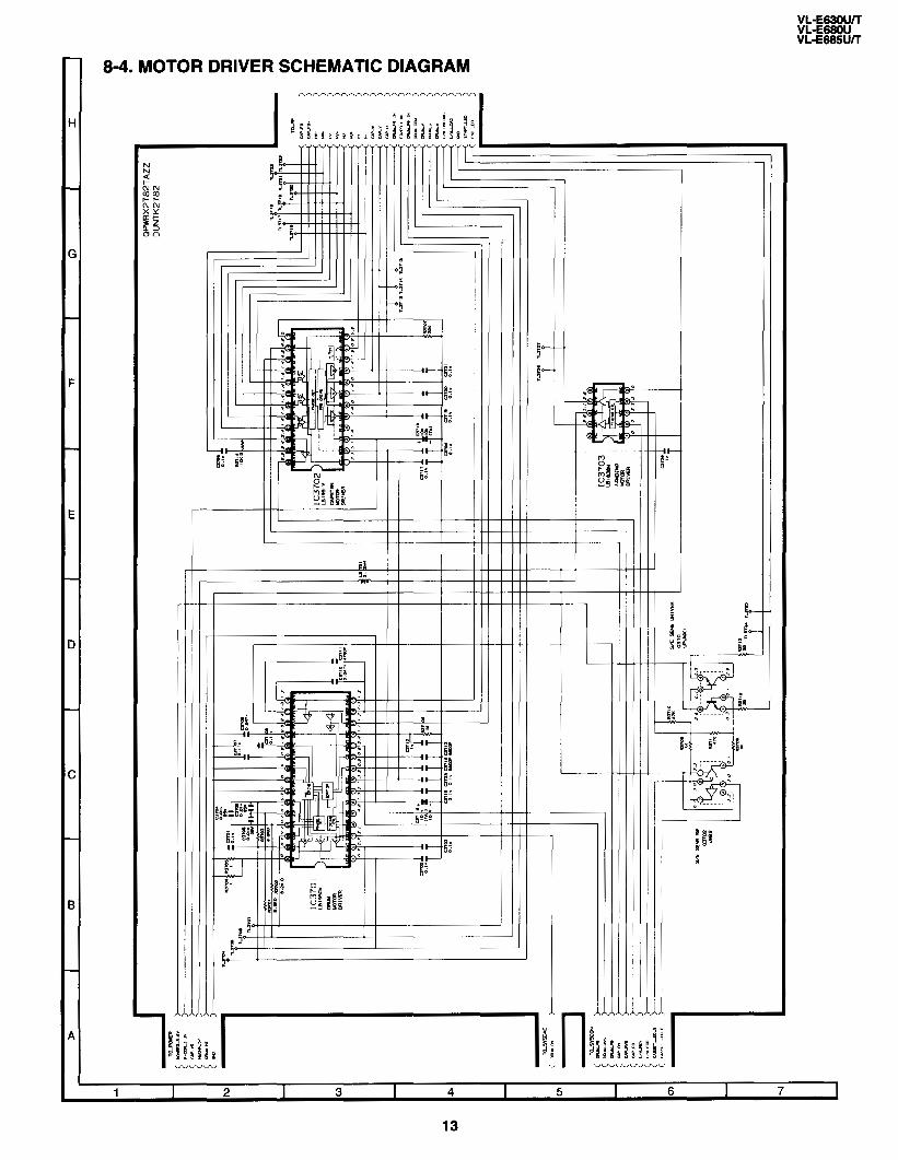
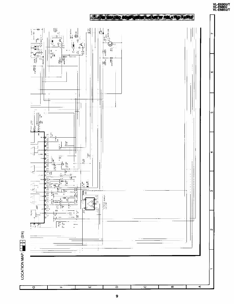
8-4. MOTOR DRIVER SCHEMATIC DIAGRAM
K
71
I I I I 1
---
1 I 2 I 3 I 4 I 5 I 6 I 7 1
13

kE~uwr vL-E66!w/-r
8-5. LCD DISPLAY CIRCUIT SCHEMATIC DIAGRAM
I /
_
-pfl “0
9 mt
&. :; ::%I
L
14

I - -
-
_ _
_ _
166 / Y--
I I i

l-l r
I I- -c
16

VL-E630UK VL-E66OU VL-E666UIT
11 i
ta In
t
t . E

8-6. RF CIRCUIT SCHEMATIC DIAGRAM
H
G
F
E
D
C
6
A
-
c
TO_YC
Fc 1:
r
QPWX2782TAZZ DUNTK2782
4 a I !j
2 v r
1 I 2 I 3 I 4 I 5 I 6 I 7 1
18

I 7 I 8 I 9 I 10 I 11 I 12 I 13 I
19
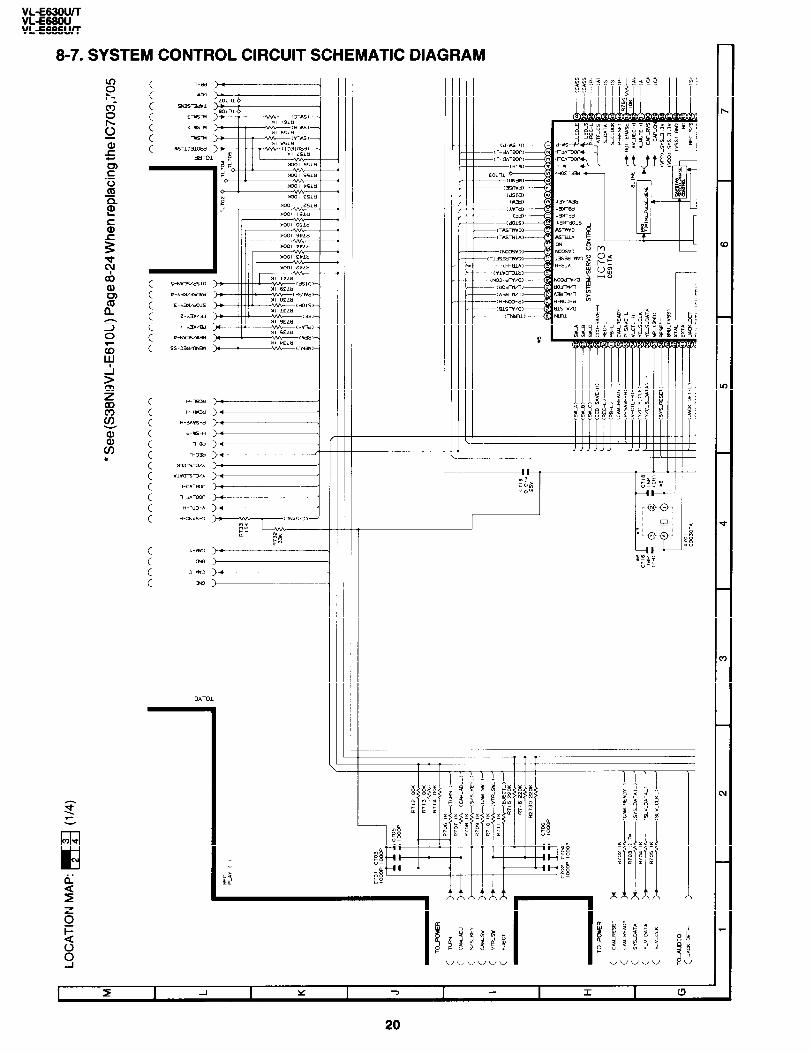
8-7. SYSTEM CONTROL CIRCUIT SCHEMATIC DIAGRAM
_
8 0 c

VL-E63OW VL-E68OU VL-E6WJK

:‘ :I
_ _ _

t i I T
t
t
t t
i 1 I
------ I
23
LO
CA
TIO
N
MA
P:
m
(l/4
)
l S
ee (
S38
N9V
L-E
61O
U)P
age
8-23
Whe
n re
plac
ing
the
IC40
1
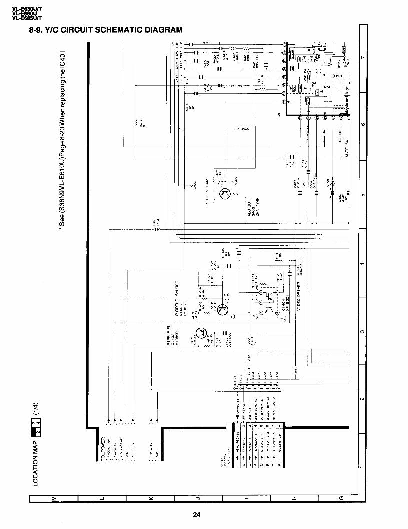
TO
-PO
WE
R
( P
-cm
L4 9
” 1:
C-N
T
SA
UR
CE
01
403
C53
83F
RIP
PLE
F
L
0140
2 A
1989
R
AD
J B
UF
04
06
2PA
,7
74,-
i
VID
EO
D
R,“
ER
;;:
;:,,,

- I - l-l-l- -1 III1 I I I -
- -
c
A-
+
25
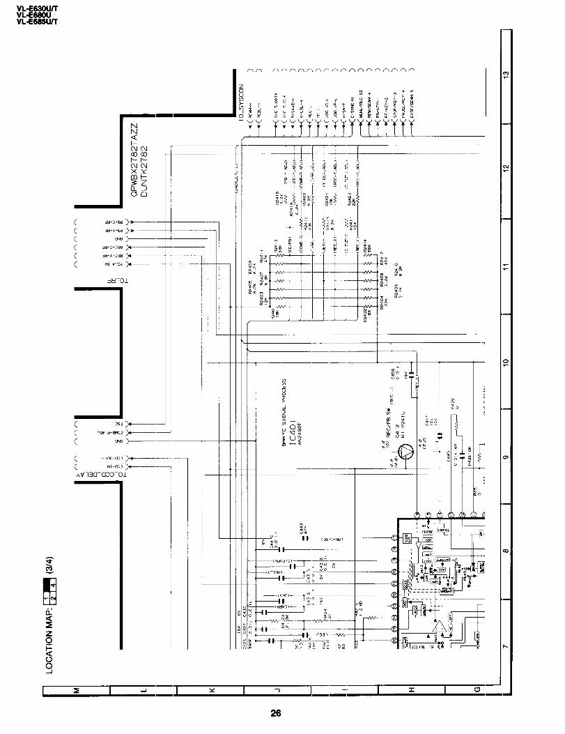
LO
CA
TIO
N
MA
P:
Eq
(3
/4)
QP
WB
X27
82T
AZ
Z
I I
I
I I
I I
I I
DU
NT
K27
82
,
t I 8-K
S
lGN
AL
PR
OC
ES
S
IC40
1 A
N24
92F

JJJJJJJJJJ ’ I
I I I I
C .
1
I 1 I I +
6 :
c C r
a
a
P
I a I LL I w I n I 0 I m I a
27
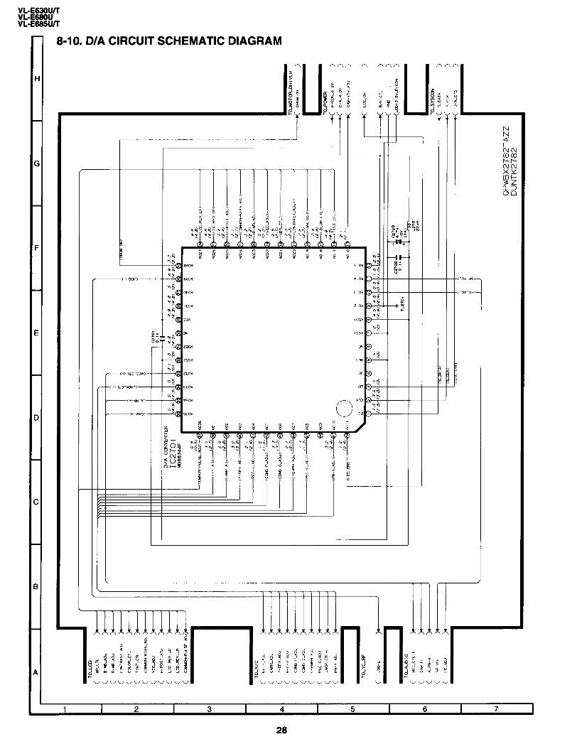
8-10. D/A CIRCUIT SCHEMATIC DIAGRAM
i% :I
-
_
_
_
_
_
-
t
1 T -
-
-
_
-
- = = II = _
28
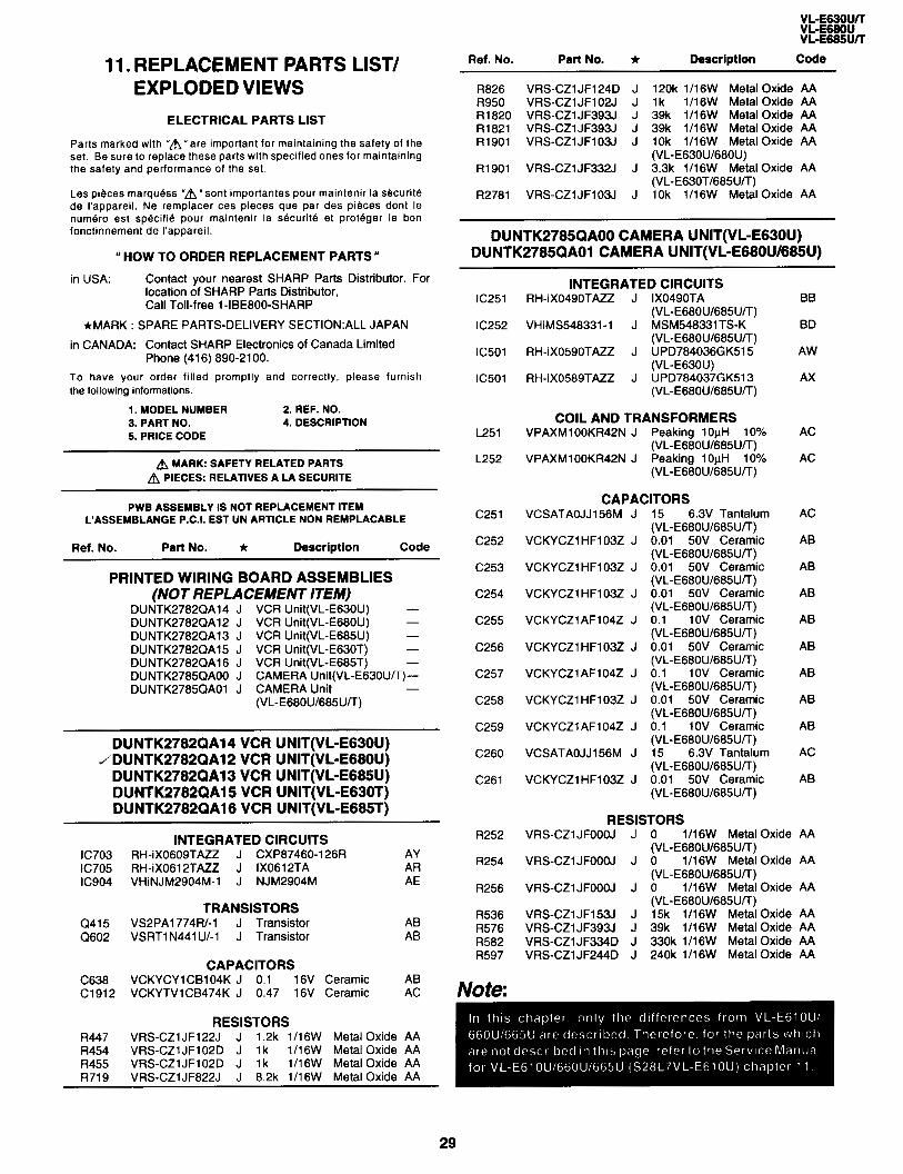
11. REPLACEMENT PARTS LIST/ EXPLODED VIEWS
ELECTRICAL PARTS LIST
Pans marked with “A” are important for maintaining the safety of the set. Be sure to replace these parts with specified ones for maintaining the safety and performance of the set.
Les pieces marquess “A” sont importantes pour maintenir la securite de I’appareil. Ne remplacer ces pieces que par des pieces dont le numero est specific pour maintenir la securite et proteger le bon fonctinnement de I’appareil.
(( HOW TO ORDER REPLACEMENT PARTS *
in USA: Contact your nearest SHARP Parts Distributor. For location of SHARP Parts Distributor, Call Toll-free 1-IBEBOO-SHARP
*MARK : SPARE PARTS-DELIVERY SECTION:ALL JAPAN
in CANADA: Contact SHARP Electronics of Canada Limited Phone (416) 890-2100.
To have your order filled promptly and correctly, please furnish the following informations.
1. MODEL NUMBER 2. REF. NO. 3. PART NO. 4. DESCRfPTlON 5. PRICE CODE
A MARK: SAFETY RELATED PARTS A PIECES: RELATIVES A LA SECURITE
PWB ASSEMBLY IS NOT REPLACEMENT ITEM L’ASSEMBLANGE P.C.I. EST UN ARTICLE NON REMPLACABLE
Ref. No. Part No. Ir Description Code
PRINTED WIRING BOARD ASSEMBLIES (NOT REPLACEMENT ITEM)
DUNTK2782QA14 J DUNTK2782QAl2 J DUNTK2782QAl3 J DUNTK2782QAl5 J DUNTK2782QAl6 J DUNTK2785QAOO J DUNTK2785QAOl J
VCR Unit(VL-E63OU) - VCR Unit(VL-E680U) - VCR Unit(VL-E685U) - VCR Unit(VL-E63OT) - VCR Unit(VL-E685T) - CAMERA Unit(VL-E630U/T)- CAMERA Unit (vL-E68ou/685u/T) -
DUNTK2782QA14 VCR UNIT(VL-E830U) / DUNTK2782QA12 VCR UNIT(VL-E880U)
DUNTK2782QA13 VCR UNIT(VL-E885U) DUNTK2782QA15 VCR UNIT(VL-E630T) DUNTK2782QA16 VCR UNIT(VL-E685T)
INTEGRATED CIRCUITS IC703 RH-iX0609TAZZ J CXP87460-126R AY IC705 RH-iX0612TAZZ J IX0612TA AR IC904 VHiNJM2904M-1 J NJM2904M AE
Q415 Q602
TRANSISTORS VS2PAl774R/-1 J Transistor VSRTl N441 U/-l J Transistor
AB AB
CAPACITORS C638 VCKYCYlCBl04K J 0.1 16V Ceramic Cl912 VCKYTVlCB474K J 0.47 16V Ceramic
AB AC
RESISTORS R447 VRSCZlJFl22J J 1.2k lIl6W Metal Oxide AA R454 VRS-CZlJFl02D J 1 k 1116W Metal Oxide AA R455 VRSCZlJFl02D J 1 k 1/16W Metal Oxide AA R719 VRSCZlJF822J J 8.2k 1/16W Metal Oxide AA
Ref. No. Part No.
R826 VRS-CZl JFl24D R950 VRS-CZl JF102J R1820 VRS-CZl JF393J Rl821 VRS-CZl JF393J Rl901 VRS-CZl JFlO3J
Rl901 VRS-CZl JF332J
R2781 VRS-CZl JFlO3J
* -
J J J J J
J
J
Description Code
120k lll6W Metal Oxide AA lk l/l 6W Metal Oxide AA 39k lil6W Metal Oxide AA 39k 1116W Metal Oxide AA 10k 1116W Metal Oxide AA (VL-ESSOU/68OU) 3.3k 1116W Metal Oxide AA (VL-E630T/685U/T) 1 Ok 1/16W Metal Oxide AA
DUNTK2785QAOO CAMERA UNIT(VL-E630U) DUNTK2785QAOl CAMERA UNIT(VL-E680U/685U)
IC251
lC252
IC501
IC501
L251
L252
c251
C252
C253
C254
C255
C256
C257
C258
c259
C260
C261
R252
R254
R256
R536 R576 R582 R597
INTEGRATED CIRCUITS RH-iX0490TAZZ J IX0490TA
(VL-E68OU/685U/T) VHiMS548331-1 J MSM548331TSK
(VL-E68OU/685U/T) RH-iXO59OTAZZ J UPD784036GK515
(VL-E630U) RH-iX0589TAZZ J UPD784037GK513
(VL-E68OU/685U/-T)
COIL AND TRANSFORMERS VPAXMlOOKR42N J Peaking 10pH 10%
(VL-E680U/685U/T) VPAXMlOOKR42N J Peaking 1 OpH 10%
(VL-E680U/685U/T)
CAPACITORS VCSATAOJJl56M J 15 6.3V Tantalum
(VL-E680U/685U/T) VCKYCZl HFl03Z J 0.01 50V Ceramic
(VL-E680U/685U/T) VCKYCZlHFlO3Z J 0.01 50V Ceramic
(VL-E680U/685U/-T) VCKYCZl HFl03Z J
VCKYCZl AFl04Z J
VCKYCZI HFIOSZ J
VCKYCZl AFlO4Z J
VCKYCZl HFlO3Z J
VCKYCZl AFlO4Z J
VCSATAOJJl56M J
VCKYCZlHFlOSZ J
0.01 50V Ceramic (VL-E68OU/685U/T) 0.1 1 OV Ceramic (VL-E68OU/685U/T) 0.01 50V Ceramic (VL-E680U/685U/-T) 0.1 1 OV Ceramic (VL-E68OU/685U/-T) 0.01 50V Ceramic (VL-E680U/685U/-T) 0.1 1 OV Ceramic (VL-E68OU/685U/T)
6.3V Tantalum ~VSL-ESSOU/~~~UI-T) 0.01 50V Ceramic (VL-E680U/685U/T)
RESISTORS VRS-CZlJFOOOJ J 0 l/l 6W Metal Oxide
(VL-E68OU/685U/T) VRS-CZlJFOOOJ J 0 l/l 6W Metal Oxide
(VL-E68OU/685U/T) VRS-CZlJFOOOJ J 0 l/l 6W Metal Oxide
(VL-E68OU/685U/-T) VRS-CZl JFl53J J 15k 1116W Metal Oxide VRSCZlJF393J J 39k 1/16W Metal Oxide VRSCZlJF334D J 330k 1/18W Metal Oxide VRSCZiJF244D J 240k 1/16W Metal Oxide
BB
BD
AW
AX
AC
AC
AC
AB
AB
AB
AB
AB
AB
AB
AB
AC
AB
AA
AA
AA
AA AA AA AA
29
k&E= VL-E665UTT
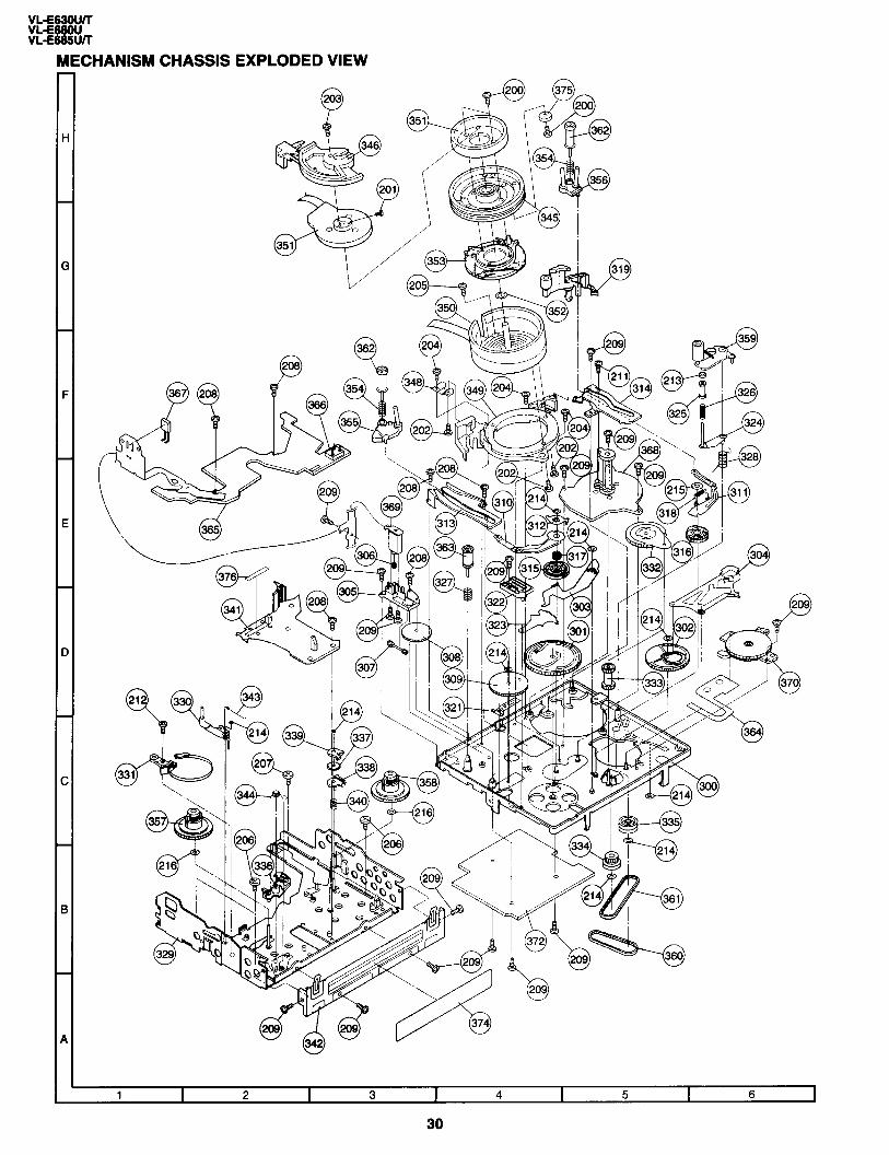
MECHANISM CHASSIS EXPLODED VIEW
I
i

Ref. No. Part No. + Description Code Ref. No. Part No. t Description Code
MECHANISM PARTS 374 375 376 200 201 202 203 204 205 206 207 208 209 211 212 213 214
TLABH0196TAZZ J PSHEM0014GEZZ J PSHEP0013GEZZ J XAPSF17P03200 J LX-XZ3036GEFP J LX-BZ3175GEFN J LX-BZ3163GEFN J LX-HZ3074GEFN J LX-BZ3177GEFF J LX-BZ3132GEFF J LX-BZ3178GEZZ J LX-HZ3083GEFF J LX-HZ3077GEFN J LX-HZ3084GEFF J LX-HZ31 16GEFD J LX-NZ3053GEZZ J LX-WZ1076GE02 J
215 LX-WZl075GE02 J
216 XWHJZ12-02040 J
Caution Label AB Counter Balance AC Interruption Sheet AC Screw Ml .7x3.2 AA Screw M2.0x6.0 AD Screw Ml .7x4.0 AC Screw Ml .7x2.5 AC Screw Ml .7x5.3 S Tight AA Screw Ml .4x1.5 AB Screw Ml .4x1.5xD3.5
300 301 302 303 304 305 306 307 308 309 310 311 312 313 314 315 316 317
LCHSMOl63GEZZ J NGERH1280GEZZ J NGERH1281GEZZ J MLEVF0470GEFW J MLEVF0492GEFW J LHLDZl966GEZZ J NGERWl064GEZZJ NGERW1065GEZZJ NGERH1282GEZZ J NGERHl283GEZZ J MARMMOl26GEZZJ MARMMOl28GEZZJ LANGAOOBOGEFW J PGiDMOl46GEZZ J PGiDM0171 GEZZ J NGERH1284GEZZ J NGERH1285GEZZ J MSPRD0167GEZZ J
318 MSPRT0407GEZZ J
319 321 322 323 324 325 326 327 328 329 330 331 332 333 334 335 336 337 338 339 340 341 342 343 344 345 346 348 349 350 351 352 353 354 355 356 357 358 359 360 361 362 363 364
MLEVP0310GEZZ J MSLiF0074GEFW J PGiDM0148GEZZ J NGERH3045GEFWJ MLEVF0472GEZZ J PGiDP0027GEZZ J MSPRC0183GEZZ J MSPRC0184GEZZ J MSPRCO208GEZZ J CCHSS0049GEOl J MLEVF0495GEZZ J LBNDK3023GEZZ J NiDR-0016GEZZ J NGERH1286GEZZ J NGERH1287GEZZ J NPLYV0157GEZZ J MLEVP0284GEZZ J NGERH1288GEZZ J MLEVP0285GEZZ J MLEVP0286GEZZ J MSPRD0169GEZZ J LHLDZ2053GEZZ J LANGG91 MGEFWJ MSPRT0408GEZZ J MSPRD0170GEZZ J CDRMU0032GEOl J PGiDMOl54GEZZ J QBRSK0039GEZZ J PGiDMOl43GEZZ J DDRML0020HEOi J RMOTPl137GEZZ J PSPAQOOlOGEZZ J NRTR-0096GEZZ J MSPRC0209GEZZ J LPOLMOO58GEZZ J LPOLMOO59GEZZ J NDAiV1071GEZZ J NDAiVl072GEZZ J MLEVFO517GEZZ J NBLTT0012GEZZ J NBLTT0013GEZZ J NROLPO108GEZZ J NROLPOlOSGEZZ J QPWBH5428GEZZ J CPWBN5402GEOl J QSW-MOO42GEZZ J RDTCHOO37GEZZ J RMOTVl 01 SGEZZ J RMOTM1075GEZZJ QSW-R0038GEZZ J
Main Chassis Ass’y Main Cam Sub-Cam Eject Lever M Function Lever L Block Holder Worm Pulley Worm Worm Wheel Lo Relay Gear S Lo Arm Ass’y T Lo Arm Ass’y S Lo Arm Retainer Sup Rail Tu Rail Sup Lo Gear Tu Lo Gear S Lo Arm Double-Acting Spring T Lo Arm Double-Acting Spring HC Lever Ass’y Ten Arm Operation Lever Ten Arm Guide Segment Gear Tu Guide Ass’y Tu Guide Tu Guide Spring Si Roller Sprint Tu Guide Lever Spring Slide Chassis Ass’y Ten Arm Ass’y Ten Band Ass’v Swing Gear A&y Drivina Gear Pulley”Gear Relay Pulley S Brake Tu Brake Gear Tu Main Brake Tu Sub-Brake Tu Brake Spring Light Guide Hoiber Ass’y Down Guide Tension Spring S Brake Spring Upper Drum Ass’y Tape Guide Earth Spring Drum Base Lower Drum Ass’y Drum Motor Gap Adjusting Shim R Tr Rotor Ass’v Gr Adjusting Spring S Pole Base T Pole Base Sup Reel Support Tu Reel Support Pinch Lever Ass’y Timing Belt S Timing Belt L Guide Roller Ass’v Si Roller Ass’y Mode FPC Sensor Ass’y Recognition SW Dew Sensor Cap. Motor / Load. Motor Mode SW
AW AD AD AD AF AD AC AD AC AC AF AG AD AD
AC AC AE
AC
Screw Ml .4x1.5xD4.0 Screw Ml .4x2.5 S Tight Screw Ml .4x3.0 S Tight Screw Ml .4x4.0 S Tight Screw Ml .4x3.2 S Tight Screw Ml .4 Nut Washer D0.8xD3.0x0.2t Plastics
AD AB AA AC
AC AA
AA Washer D2.1xD5.0x0.25t Plastics Washer D1.2xD4.0x0.25t Plastics
AC
- End of Mechanism Parts - AD AC AD AC AE AA AA AC
AC
AF AC AD AD AC AC AC AC AD
AF AD AD BE AB AD AG AY AS AC AP AC AK AK AG AG AS AE AE AG AH AK
OTHERPARTS
SUPPLIED ACCESSORIES TiNSEO31 OTAZZ J
TiNSE031lTAZZ J
TiNSEOBlPTAZZ J
TiNS601lTAZZ J
TiNS-6012TAZZ J
UBATLOOllTAZZ J UBATMOOl OTAZZ J
UBATMOOl 1 TAZZ J
UBATUOO23GEZZ J RRMCG0072TASA J UADP-0274TAZZ J
Operation Manual (VL-E630U) Operation Manual (VL-E680U) Operation Manual (VL-E685U) Operation Manual (VL-E630T) bperation Manual (VL-E685T) Lithium Battery Battery (VL-E630U/680U/685U) Battery (VL-E630T/685T) AA DRYCELL Battery x 2 Remote Control AC Adapter (VL-E630U/680U/685U) AC Adapter (VL-E630T/685T)
AH AF AZ
AG
UADP-0275TAZZ J
PACKING PARTS(NOT REPLACEMENT ITEM) SPAKC7390TAZZ J Packing Case(VL-E68OU) - SPAKC7380TAZZ J Packing Case(VL-E63OU) - SPAKC7394TAZZ J Packina CaselVL-E685U) - SPAKC7384TAZZ J Packing Case(VL-E63OTj - SPAKC7395TAZZ J Packing Case(VL-E685T) -
366 367 368 369 370 372 RAMP-0017TAN0 J H/A PWB AY
31

CABINET EXP n /
‘LODED VIEW -----
I I 9
5 /\ /‘l-b ‘.
34
P
F
E
D
C
B
A
il
I I I I I I I I I I I I I I I
1 I
1 I 2 I 3 I 4 I 5 I 6 1
32

VL-E639U/T VL-E68fXf VL-E685U/T
Ref. No. Part No. * Description Code Ref. No. Pert No. Ir Description Code
CABINET PARTS LIST 7-2 7-3 7-4 7-5 8 A 9 10 11
*:: 14- 15 16 16 16 16 16 17 17 17 18 19
PSPAZOl SOTAZZ J GCOVAl537TAKA J PSPAZOl89TAZZ J LANGH0071TAFW J LHLDZ1446TAZZ J PSHEP0044TAZZ J PSHEP0045TAZZ J PSHEP0044TAZZ J PGiDM0025TAZZ J PMiR0021TAZZ J CLMPV0043TA02 J CPNLC0032RM01 -J PZETV0343TAZZ J TLABMl909TAZZ J TLABM1920TAZZ J TLABM 1924TAZZ J TLABM1913TAZZ J TLABM 1925TAZZ J TLABNOl71TAZZ J TLABNO172TAZZ J TLABNOl73TAZZ J CLNSAOl27TAOl J GFTAC1241TASA J
20 DUNTK2782QA14 J 20 DUNTK2782QA12 J 20 DUNTK2782QA13 J 20 DUNTK2782QA15 J 20 DUNTK2782QA16 J 21 DUNTK2785QAOO J 21 DUNTK2785QAOl J
22 QPWBH2814TAZZ J 23 LHLDW1038TAOO J 24 QSW-Z0286TAZZ J
24 QSW-Z0300TAZZ J
25 QTANZOl29TAZZ J 26 QSW-Z0285TAZZ J 27 LHLDZ1452TAZZ J 28 MSPRC0083TAFJ J 29 JBTN-0277TASA J
29 JBTN-0277TASB J
30 LHLDZ1451TAZZ J 31 JKNBPOlSPTASA J 32 JKNBPOl53TASA J 32 JKNBPOl53TASB J
33 LHLDZ1453TASA J 34 JKNBP0154TASA J 35 PSPAZOl 9lTAZZ J 36 RMiCC0079TAZZ J 37 MSPRT0034TAFJ J 38 LHLDZ1454TAOO J 39 NSFTZOOWTAFW J 40 PSPAZO192TAZZ J 41 LHLDZ145OTAZZ J 42 VSP0020P-94WN J 43 PSPAGOlO3TAZZ J 44 PCOVP9062TAZZ J 45 PSPAGOOOSTAZZ J 46 GCOVA3056TAKA J 47 ZTAPEZ800020E J 48 QSW-Z0284TAZZ J 49 MLEVP0031TAZZ J 50 LANGK0399TAFW J 51 PSHEPOO74TAZZ J 52 QJAKZ0071TAZZ J 53 PSPAG0084TAOO J
Tilt Spacer AE Tilt Frame V AL Rotation Spacer AD
1
1
DCABA6183TAKl J
DCABA6183TAK2 J
1-2 PSPAG0095TAZZ J l-3 TLABH0326TAZZ J
l-4 LHLDBlO27TAZZ J 2 DCABB6183TAK5 J
2 DCABB6183TAK6 J
2-2 QEARP0233TAZZ J 2-3 TLABHO318TAZZ J
2-4 GCOVH 1228TASA J 2-5 GCOVAl535TAZZ J
2-6 ZTAPEZ800020E J 3 CCABC6090TAK2 J
3 CCABC6091 TAK4 J
3-2 GCOVAl539TASB J 4 DCABD6090TAK2 J
4 DCABD6088TAK4 J
4 DCABD6093TAK2 J
4 DCABD6094TAK2 J
4-2 JBTN-0276TASA J
4-2 JBTN-0276TASB J
4-2 JBTN-0277TASA J 4-2 JBTN-0277TASB J 5 DFTAC1271TAKl J
5 DFTACl272TAKl J 5 DFTACl273TAKl J
5-2 HBDGSOO59TASB J 5-3 LANGKO428TAFW J 5-4 LANGK0400TAFW J 5-5 PSPAZOl93TAZZ J 5-6 MSPRD0047TAFJ J 6 CCOVAl536TAK5 J
6 CCOVAl536TAK8 J 6-2 NSFTZ0049TAFW J 6-3 MSPRD0050TAFJ J 6-4 TLABH0264TAZZ J 6-5 GFTABl066TAKA J 6-6 HDECPO045TASA J
6-6 HDEC P0047TASA J
6-7 LHLDZl448TAOO J 6-8 MSPRCOl03TAFJ J
6-9 MSPRC0102TAFJ J 6-10 MLEVP003OTASA J
6-11 6-12 6-13 6-14 6-15 6-16 7
LHLDZ1449TAZZ J MLEVPOO29TASA J MSPRCOlOlTAFJ J LHLDZ1445TAZZ J LANGK0398TAOO J UBNDTOlPSTAZZ J DCOVAl538TAKl J Tilt A&y AU
V Frame Service AL (VL-E630U/680U/685U) V Frame Service ’ (VL-E630T/685T) VCR Lid Cushion AA Liiium Exchange Label AB (Only VL-E630TI685T) Lithium Holder AD L Cabinet Service AS (VL-E630U/680U/685U) L Cabinet Service (VL-E630TI685T) LCD Earth Sheet AE Facing Recording Caution AB Label Jack Cover AD Remote Control Receptor AD Cover Tape -
Stopper Fktfng AD LCD Holder AG ReflectIon Polarizing Sheet AG Diffusion Sheet AD Prism Sheet AG Light Guide Plate AG Reflection Sheet AC Lamp lnverter Unit LCD Panel BZ LCD Glass Retaining AA Model Label(VL-E630U) AC Model Label(VL-E680U) AC Model Label(VL-E685U) AC Model Label(VL-E63OT) AC Model LabekVL-E685T) AC Serial No. Label(VL-E638U) AC Serial No. Labef(VL-E68OU) AC Serial No. Label(VL-E685U) AC Lens Unit BS Cassette Compartment AD Cover VCR Unit(VL-E63OU) - VCR Unit(VL-E68OUj - VCR Unit(VL-E685U) - VCR Unit(VL-E63OT) - VCR Unit(VL-E685T) - CAMERA UnitNL-E63OUfl) - CAMERA Unit (VL-E68OU/685U/T) - Tilt FPC AQ FPC Holder AC VCR Operation Unit AR
Camera Front Cabinet AT Ass’vNL-E63OUIT) Cam&a Front Cabinet Ass’y(VL-E680U/685U/) Lens Hood AK Camera Back Cabinet A0 Ass’y(VL-E63OU) Camera Back Cabinet AS Ass’y(VL-E680U/685U) Camera Back Cabinet Ass’y(VL-E630T) Camera Back Cabinet Ass’y(VL-E685T) Camera Button AD (VL-E63OU) Camera Button AF
(vL-E63ou/68ou/685u) VCR Ooeration Unit AU (VL-E6&OT/685T)
(VL-E680U/685U) Camera ButtonlVL-E63OT) AD Camera Button(VL-E685Tj AF VCR Lid Service AU (VL-ESSOU/T) VCR Lid Servfce(VL-E680U) VCR Lid Service
ⅇ;eT) AE
VCR Lid Reinforcing Angle AG Eject Fitting - - AD VCR Lid Sheet AC
Battery TerminalfUnk AG Power Unit AR Power Lock Holder AC Power Lock Spring AA Power Button AD (VL-E630U/630T) Power Button AF (VL-E680U/685U/685T) Power Holder AC Power Knob AD Zoom Knob(VL-E63OU/T) AD Zoom Knob AF (VL-E680U/685U/T) Zoom Knob Holder AD Open Knob AC Spacer AA Microphone AM Lid Lock Spring AC
VCR Lid Spring AD KS Side Cover AU (VL-E630U/680U/685U) KS Side Cover(VL-E63OT/685T) Battery Lid Axle AC Battery Lid Spring AC Recvcle Label _. AB VCR Lid Lock - AD
VCR Lid Shaft AD Bat&y Lid Batterv Decoration Plate ;E Microphone Lead Spacer
Speaker Holder Speaker Speaker Spacer Speaker Mesh VCR Lid Cushion Speaker Cover Tape Turn/Eject SW
AD AC AL AC AB AA AE -
AH
(VL-E63OU/680U/685U) Battery Decoration Plate (VL-E630T/685T) Battery Intermediate Lock Battery Intermediate Lock Spring Battery Lock Lever Spring Battery Lid Open/Close Lever Battery Lock Holder Battery Lock Lever Battery Push-out Spring Lens Holder Battery Lid Angle Fitting Hand Strap
AC
AC AD
AA AC
Eject Lever AC Tripod Angle Ass’y AK Microphone Lead Sheet AB
AC AC AD AD AH
Jack Unit Front Grouo Frame AD Rubber ’ Microphone Cover CCD FPC
GCOVA3057TAKA J QPWBH2815TAZZ J
AG AE
33

Ref. No. Part No. Ir Description Code Ref. No. Part No. * Description Code
a b
:
LX-HZ001 8TAFN J LX-HZ001 8TAFF J LX-HZ0045TAFN J XiPSF2OPO4000 J
LX-BZOl 91 TAFD J XiPSD2OP03000 J LX-UZOOlGTAFD J LX-BZ02OOTAFD J XiPSN20PO4000 J LX-HZOO63TAFC J
M2x6 Tapping, Silver M2x6 Tapping, Black M2x4 Tapping, Silver M2x4 Small Screw, Black Zinc Plating M2 Special Screw M2x3 Screw M2x5 Special Screw M2x7 Special Screw M2x4 Small Screw, Silver Ml .7x6 Tapping, Silver
AA
E AA
AC AA
E AA AA
- End of Cabinet Parts -
CASSElTE HOUSING PARTS
400 CHLDX3077GEOl J Cassette Compartment AY
401 402 403
Assy . MSPRTO414GEZZ J Up Main Spring AD MROD-0014GEFJ J DamDer rod AG PDMP-0013GEZZ J Cassette Compartment AG
Damper
- End of Cassette Housina Parts -
CASSElTE HOUSING CONTROL UNIT
I
P 400 \ ,
r- I /
/ I
I
I
I
/ I /
,
\ \
\ \
\
L
\ / L_______’
1 I 2 I 3 I 4 I 5 I 6 I

VL-E630W VL-E68OU VL-E685U/T
12. PACKING OFTHE SET
GCOVH1225TASA
QCw.l\]
UBNDSOOlOTASA I (Shoulder Strap) d
(Remote Control) xQh& RRMCG0072TASA
(A/V Cable)
JrSPAKA6176TAZZ (Packing ADD.)
>leUADP-0274TAZZ
UBATMOOl OTAZZ >I<UBATMOOllTAZZ
(Battery) UBATLOOl ITAZZ (Lithium Battery)
UBATU0023GEZZ A DRYCELL Battery x 2)
*SPAKA6201TAZZ (Packing ADD.)
1
*SPAKP6049TAZZ (Wrapping Paper)
kSPAKA6237TAZZ (Packing ADD.)
/
(Packin: Case) * Not Replacement Item * For detail, See page 31.
35

kEw vL:EsffluK
Dec. 1998 Printed in JAPAN SA. NS
SHARP COPYRIGHT @ 1998 BY SHARP CORPORATION
ALL RIGHTS RESERVED.
No part of this publication may be reproduced,
stored in a retrieval system, or transmitted in
any form or by any means, electronic, mechanical,
photocopying, recording, or otherwise, without
prior written permission of the publisher.
SHARP CORPORATION AV Systems Group Quality & Reliability Control Center Yaita, Tochigi 329-2193, Japan