Embed Size (px)
Citation preview
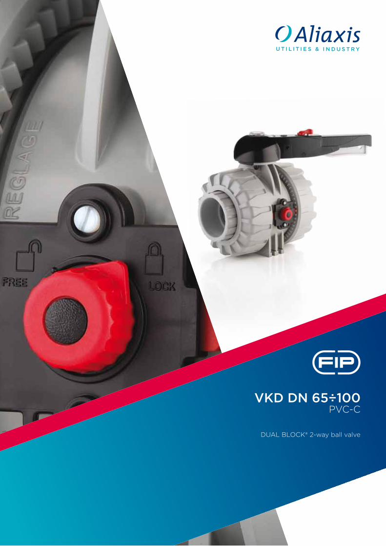
VKD DN 65÷100PVC-C
Dual BloCk® 2-way ball valve
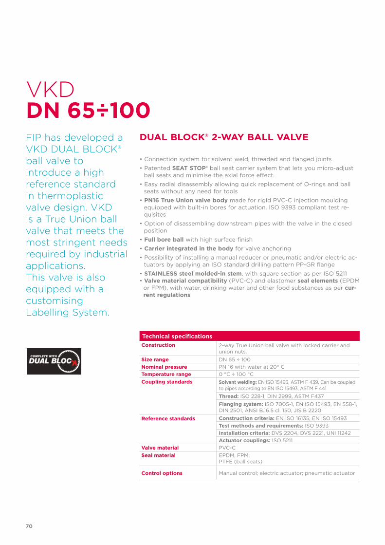
FIP has developed aVkD Dual BloCk®ball valve to introduce a high reference standard in thermoplastic valve design. VkD is a True union ball valve that meets the most stringent needs required by industrial applications.This valve is alsoequipped with acustomisinglabelling System.
70
Technical specificationsConstruction 2-way True Union ball valve with locked carrier and
union nuts.Size range DN 65 ÷ 100Nominal pressure PN 16 with water at 20° CTemperature range 0 °C ÷ 100 °CCoupling standards Solvent welding: EN ISO 15493, ASTM F 439. Can be coupled
to pipes according to EN ISO 15493, ASTM F 441Thread: ISO 228-1, DIN 2999, ASTM F437Flanging system: ISO 7005-1, EN ISO 15493, EN 558-1,DIN 2501, ANSI B.16.5 cl. 150, JIS B 2220
Reference standards Construction criteria: EN ISO 16135, EN ISO 15493Test methods and requirements: ISO 9393Installation criteria: DVS 2204, DVS 2221, UNI 11242Actuator couplings: ISO 5211
Valve material PVC-CSeal material EPDM, FPM;
PTFE (ball seats)
Control options Manual control; electric actuator; pneumatic actuator
VkD
DuAl BloCk® 2-wAy BAll VAlVe
• Connection system for solvent weld, threaded and flanged joints• Patented SeAT SToP® ball seat carrier system that lets you micro-adjust
ball seats and minimise the axial force effect.• Easy radial disassembly allowing quick replacement of O-rings and ball
seats without any need for tools• PN16 True union valve body made for rigid PVC-C injection moulding
equipped with built-in bores for actuation. ISO 9393 compliant test re-quisites
• Option of disassembling downstream pipes with the valve in the closed position
• Full bore ball with high surface finish• Carrier integrated in the body for valve anchoring• Possibility of installing a manual reducer or pneumatic and/or electric ac-
tuators by applying an ISO standard drilling pattern PP-GR flange• STAINleSS steel molded-in stem, with square section as per ISO 5211• Valve material compatibility (PVC-C) and elastomer seal elements (EPDM
or FPM), with water, drinking water and other food substances as per cur-rent regulations
DN 65÷100
71
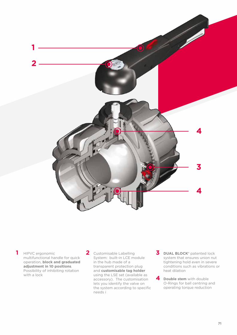
1 HIPVC ergonomic multifunctional handle for quick operation, block and graduated adjustment in 10 positions. Possibility of inhibiting rotation with a lock
2 Customisable Labelling System: built-in LCE module in the hub made of a transparent protection plug and customisable tag holder using the LSE set (available as accessory). The customisation lets you identify the valve on the system according to specific needs i
3 DuAl BloCk® patented lock system that ensures union nut tightening hold even in severe conditions such as vibrations or heat dilation
4 Double stem with double O-Rings for ball centring and operating torque reduction
1
2
3
4
4
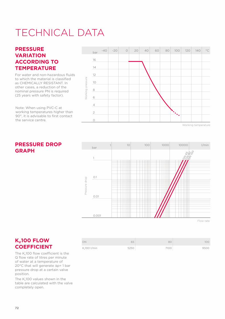
PReSSuRe DRoP GRAPH
Pre
ssu
re d
rop
Flow rate
bar1 10 100 1000 10000 l/min
1
0.1
0.01
0.001
DN
65
DN
80
DN
100
72
TeChnICal DaTa
-40 -20 0 20 40 60 80 100 120 140 °C
16
14
12
10
8
6
4
2
0
Wo
rkin
g p
ress
ure
Working temperature
barPReSSuRe VARIATIoN ACCoRDING To TeMPeRATuReFor water and non-hazardous fluids to which the material is classified as CHEMICALLY RESISTANT. In other cases, a reduction of the nominal pressure PN is required (25 years with safety factor).
kV100 Flow CoeFFICIeNTThe Kv100 flow coefficient is the Q flow rate of litres per minute of water at a temperature of 20°C that will generate ∆p= 1 bar pressure drop at a certain valve position.The Kv100 values shown in the table are calculated with the valve completely open.
DN 65 80 100
Kv100 l/min 5250 7100 9500
Note: When using PVC-C at working temperatures higher than 90°, it is advisable to first contact the service centre.
73
The information in this leaflet is provided in good faith. no liability will be accepted concerning technical data that is not directly covered by recognised international standards. FIP reserves the right to carry out any modification. Products must be installed and maintained by qualified personnel.
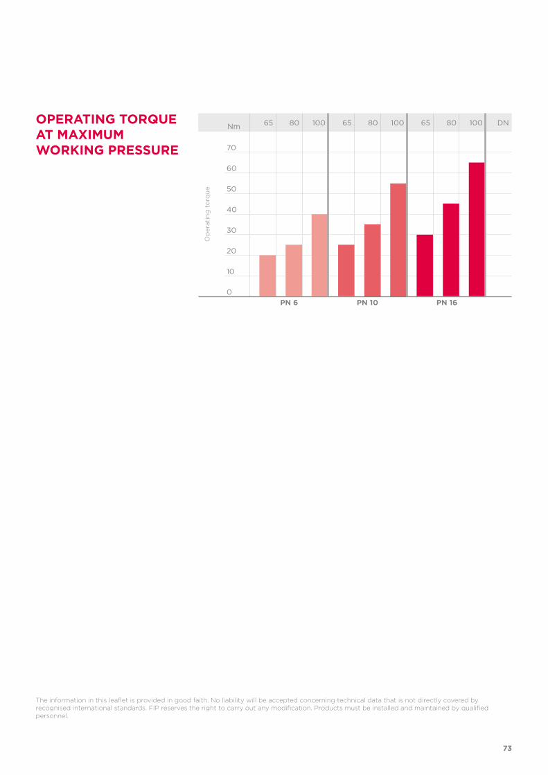
oPeRATING ToRque AT MAxIMuM woRkING PReSSuRe
Nm 65 80 100 65 80 100 65 80 100 DN
70
60
50
40
30
20
10
0
op
erat
ing
to
rqu
e
PN 6 PN 10 PN 16
d DN PN B B1 C C1 E H H1 L Z g EPDM Code FPM Code
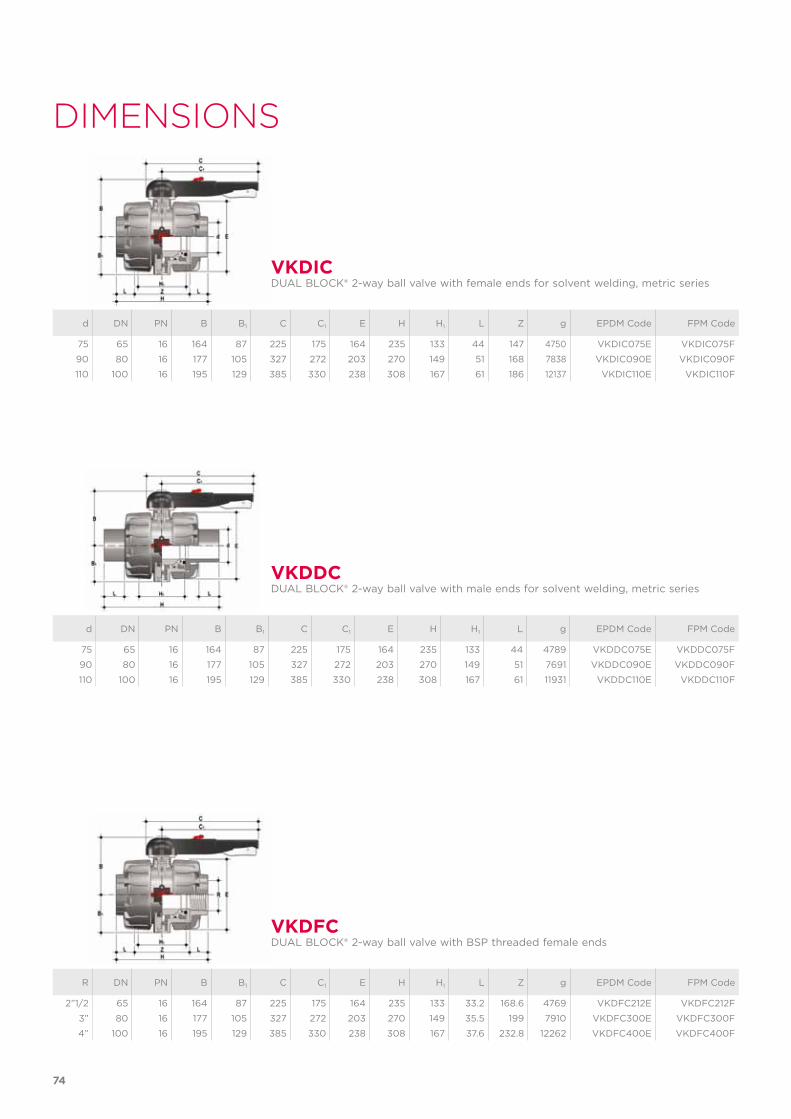
75 65 16 164 87 225 175 164 235 133 44 147 4750 VKDIC075E VKDIC075F
90 80 16 177 105 327 272 203 270 149 51 168 7838 VKDIC090E VKDIC090F
110 100 16 195 129 385 330 238 308 167 61 186 12137 VKDIC110E VKDIC110F
R DN PN B B1 C C1 E H H1 L Z g EPDM Code FPM Code
2”1/2 65 16 164 87 225 175 164 235 133 33.2 168.6 4769 VKDFC212E VKDFC212F
3” 80 16 177 105 327 272 203 270 149 35.5 199 7910 VKDFC300E VKDFC300F
4” 100 16 195 129 385 330 238 308 167 37.6 232.8 12262 VKDFC400E VKDFC400F
d DN PN B B1 C C1 E H H1 L g EPDM Code FPM Code
75 65 16 164 87 225 175 164 235 133 44 4789 VKDDC075E VKDDC075F
90 80 16 177 105 327 272 203 270 149 51 7691 VKDDC090E VKDDC090F
110 100 16 195 129 385 330 238 308 167 61 11931 VKDDC110E VKDDC110F
VkDIC
VkDFC
VkDDC
DUAL BLOCK® 2-way ball valve with female ends for solvent welding, metric series
DUAL BLOCK® 2-way ball valve with BSP threaded female ends
DUAL BLOCK® 2-way ball valve with male ends for solvent welding, metric series
74
DImenSIonS
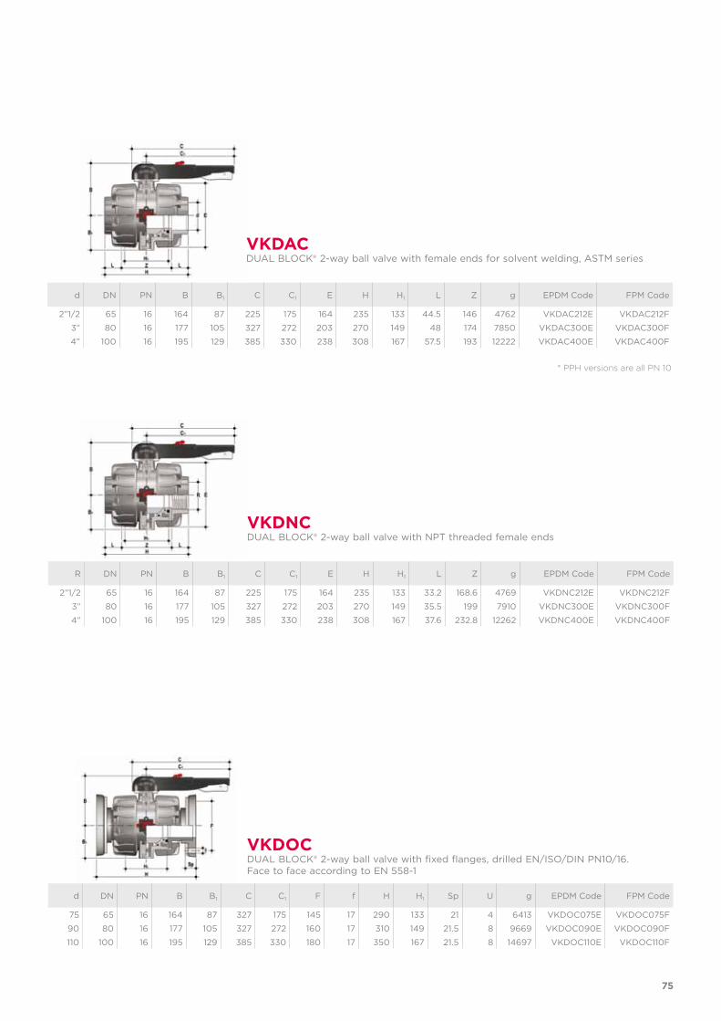
* PPh versions are all Pn 10
d DN PN B B1 C C1 E H H1 L Z g EPDM Code FPM Code
2”1/2 65 16 164 87 225 175 164 235 133 44.5 146 4762 VKDAC212E VKDAC212F
3” 80 16 177 105 327 272 203 270 149 48 174 7850 VKDAC300E VKDAC300F
4” 100 16 195 129 385 330 238 308 167 57.5 193 12222 VKDAC400E VKDAC400F
VkDACDUAL BLOCK® 2-way ball valve with female ends for solvent welding, ASTM series
R DN PN B B1 C C1 E H H1 L Z g EPDM Code FPM Code
2”1/2 65 16 164 87 225 175 164 235 133 33.2 168.6 4769 VKDNC212E VKDNC212F
3” 80 16 177 105 327 272 203 270 149 35.5 199 7910 VKDNC300E VKDNC300F
4” 100 16 195 129 385 330 238 308 167 37.6 232.8 12262 VKDNC400E VKDNC400F
VkDNCDUAL BLOCK® 2-way ball valve with NPT threaded female ends
d DN PN B B1 C C1 F f H H1 Sp U g EPDM Code FPM Code
75 65 16 164 87 327 175 145 17 290 133 21 4 6413 VKDOC075E VKDOC075F
90 80 16 177 105 327 272 160 17 310 149 21.5 8 9669 VKDOC090E VKDOC090F
110 100 16 195 129 385 330 180 17 350 167 21.5 8 14697 VKDOC110E VKDOC110F
VkDoCDUAL BLOCK® 2-way ball valve with fixed flanges, drilled EN/ISO/DIN PN10/16.Face to face according to EN 558-1
75
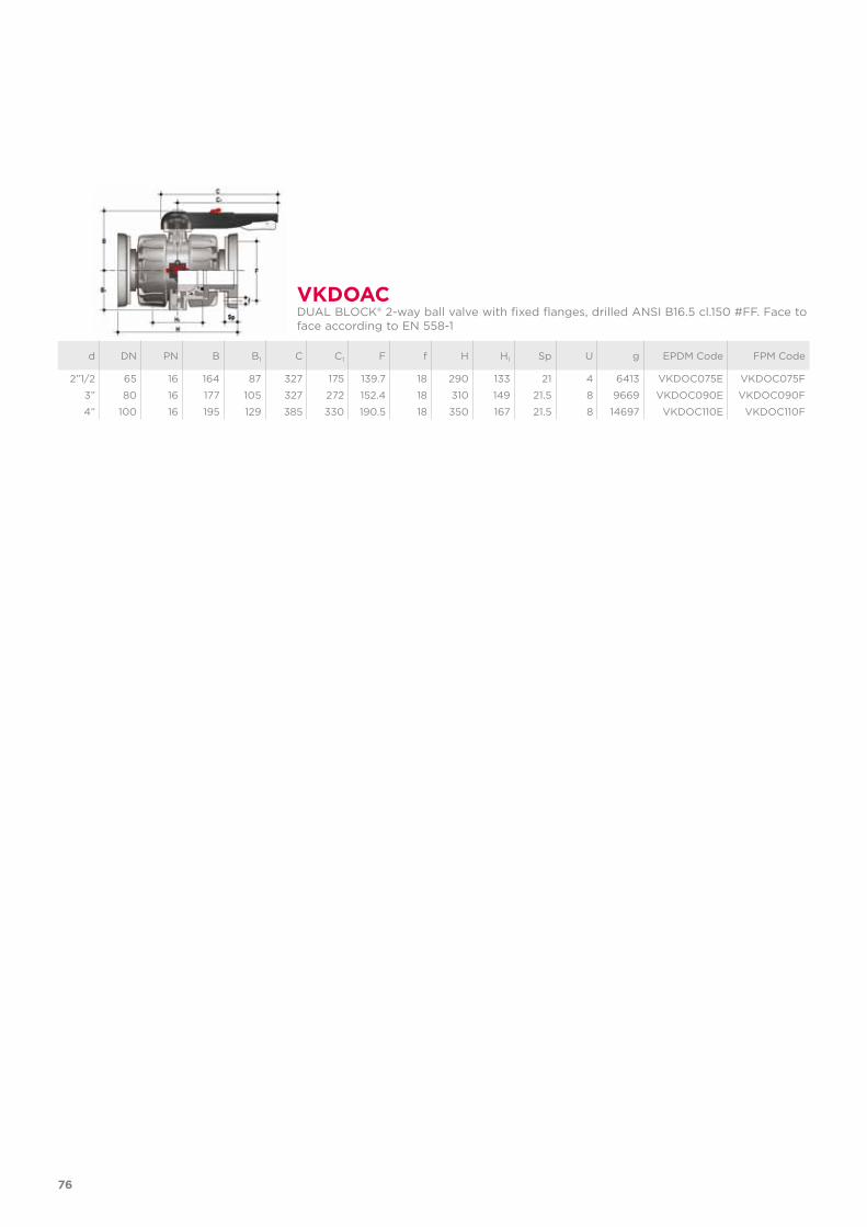
d DN PN B B1 C C1 F f H H1 Sp U g EPDM Code FPM Code
2”1/2 65 16 164 87 327 175 139.7 18 290 133 21 4 6413 VKDOC075E VKDOC075F
3” 80 16 177 105 327 272 152.4 18 310 149 21.5 8 9669 VKDOC090E VKDOC090F
4” 100 16 195 129 385 330 190.5 18 350 167 21.5 8 14697 VKDOC110E VKDOC110F
VkDoACDUAL BLOCK® 2-way ball valve with fixed flanges, drilled ANSI B16.5 cl.150 #FF. Face to face according to EN 558-1
76
aCCeSSorIeS
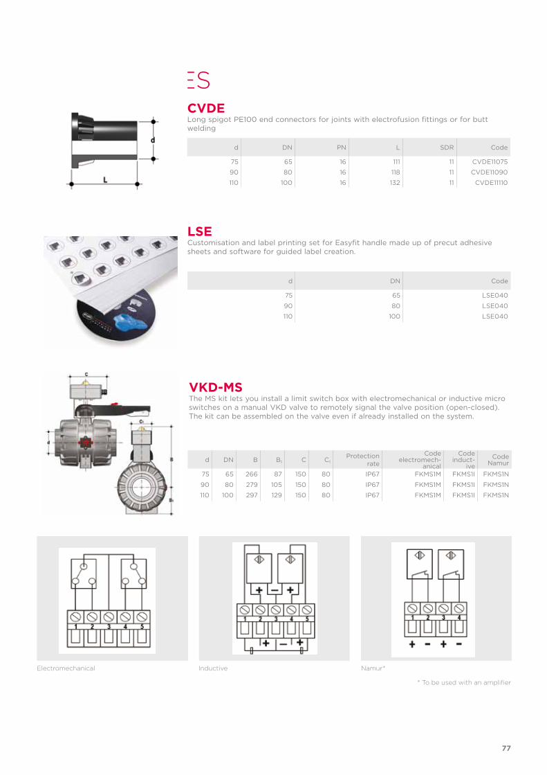
lSeCustomisation and label printing set for Easyfit handle made up of precut adhesive sheets and software for guided label creation.
d DN Code
75 65 LSE040
90 80 LSE040
110 100 LSE040
electromechanical Inductive namur*
* To be used with an amplifier
VkD-MSThe MS kit lets you install a limit switch box with electromechanical or inductive micro switches on a manual VKD valve to remotely signal the valve position (open-closed). The kit can be assembled on the valve even if already installed on the system.
d DN B B1 C C1Protection
rate
Codeelectromech-
anical
Codeinduct-
iveCode
Namur
75 65 266 87 150 80 IP67 FKMS1M FKMS1I FKMS1N
90 80 279 105 150 80 IP67 FKMS1M FKMS1I FKMS1N
110 100 297 129 150 80 IP67 FKMS1M FKMS1I FKMS1N
d DN PN L SDR Code
75 65 16 111 11 CVDE11075
90 80 16 118 11 CVDE11090
110 100 16 132 11 CVDE11110
CVDeLong spigot PE100 end connectors for joints with electrofusion fittings or for butt welding
77
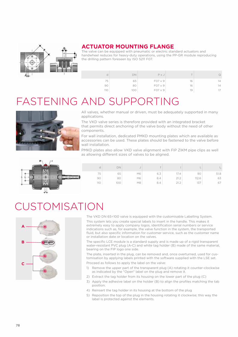
ACTuAToR MouNTING FlANGeThe valve can be equipped with pneumatic or electric standard actuators and handwheel reduces for heavy-duty operations, using the PP-GR module reproducing the drilling pattern foreseen by ISO 5211 F07.
d DN P x J T Q
75 65 F07 x 9 16 14
90 80 F07 x 9 16 14
110 100 F07 x 9 19 17
FaSTenIng anD SuPPorTIng
d DN J f I I1 I2
75 65 M6 6.3 17.4 90 51.8
90 80 M6 8.4 21.2 112.6 63
110 100 M8 8.4 21.2 137 67
All valves, whether manual or driven, must be adequately supported in many applications. The VKD valve series is therefore provided with an integrated bracket that permits direct anchoring of the valve body without the need of other components.For wall installation, dedicated PMKD mounting plates which are available as accessories can be used. These plates should be fastened to the valve before wall installation. PMKD plates also allow VKD valve alignment with FIP ZIKM pipe clips as well as allowing different sizes of valves to be aligned.
The VKD DN 65÷100 valve is equipped with the customisable Labelling System.This system lets you create special labels to insert in the handle. This makes it extremely easy to apply company logos, identification serial numbers or service indications such as, for example, the valve function in the system, the transported fluid, but also specific information for customer service, such as the customer name or installation date or location on the valves.The specific LCE module is a standard supply and is made up of a rigid transparent water-resistant PVC plug (A-C) and white tag holder (B) made of the same material, bearing on the FIP logo one side.The plate, inserted in the plug, can be removed and, once overturned, used for cus-tomisation by applying labels printed with the software supplied with the LSE set.Proceed as follows to apply the label on the valve:1) Remove the upper part of the transparent plug (A) rotating it counter-clockwise
as indicated by the "Open" label on the plug and remove it.2) Extract the tag holder from its housing on the lower part of the plug (C)3) Apply the adhesive label on the holder (B) to align the profiles matching the tab
position.4) Reinsert the tag holder in its housing at the bottom of the plug5) Reposition the top of the plug in the housing rotating it clockwise; this way the
label is protected against the elements.
CuSTomISaTIon
A
B
C
78
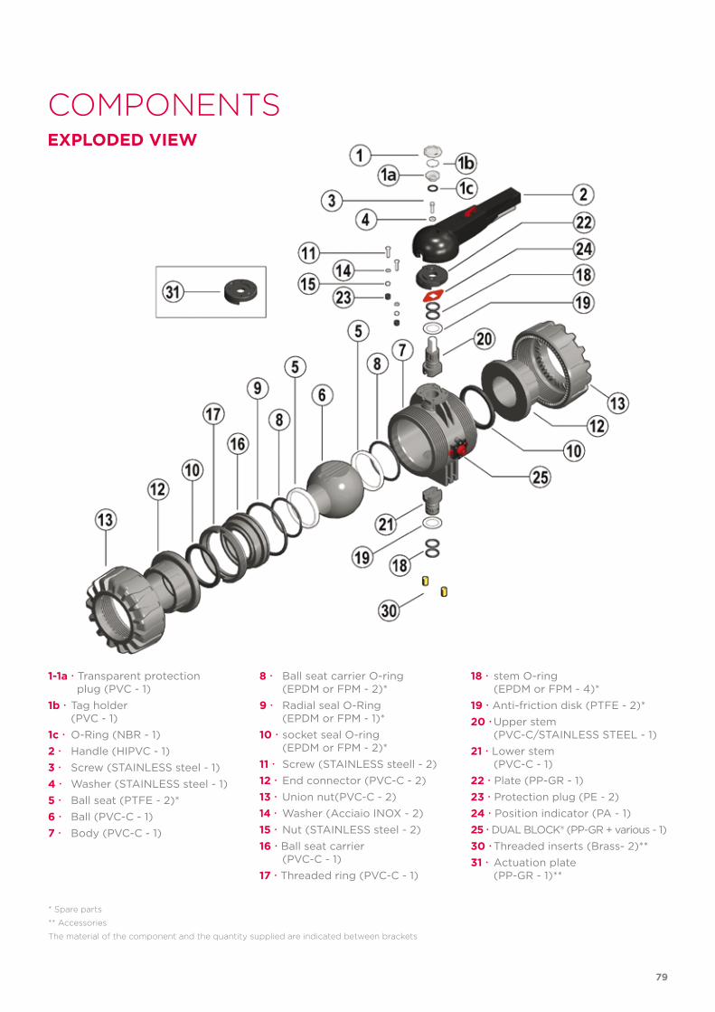
ComPonenTSexPloDeD VIew
1-1a Transparent protection plug (PVC - 1)1b Tag holder (PVC - 1)1c O-Ring (NBR - 1)2 Handle (HIPVC - 1)3 Screw (STAINLESS steel - 1)4 Washer (STAINLESS steel - 1)5 Ball seat (PTFE - 2)*6 Ball (PVC-C - 1)7 Body (PVC-C - 1)
* Spare parts
** accessories
The material of the component and the quantity supplied are indicated between brackets
8 Ball seat carrier O-ring (EPDM or FPM - 2)*9 Radial seal O-Ring (EPDM or FPM - 1)*10 socket seal O-ring (EPDM or FPM - 2)*11 Screw (STAINLESS steell - 2)12 End connector (PVC-C - 2)13 Union nut(PVC-C - 2)14 Washer (Acciaio INOX - 2)15 Nut (STAINLESS steel - 2)16 Ball seat carrier (PVC-C - 1)17 Threaded ring (PVC-C - 1)
18 stem O-ring (EPDM or FPM - 4)*19 Anti-friction disk (PTFE - 2)*20 Upper stem (PVC-C/STAINLESS STEEL - 1)21 Lower stem (PVC-C - 1)22 Plate (PP-GR - 1)23 Protection plug (PE - 2)24 Position indicator (PA - 1)25 DUAL BLOCK® (PP-GR + various - 1)30 Threaded inserts (Brass- 2)**31 Actuation plate (PP-GR - 1)**
79
InSTallaTIonBefore proceeding with installation. please follow these instructions carefully:1) Check that the pipes to be connected to the valve are aligned in order to avoid
mechanical stress on the threaded joints.2) Make sure the DUAL BLOCK® union nut lock system (25) is in the FREE position.3) Unscrew the union nuts (13) and insert them on the pipe segments.4) Solvent weld or screw the end connectors (12) onto the pipe ends.5) Position the valve body between the end connectors and fully tighten the union
nuts (13) clockwise with an appropriate wrench.6) Lock the union nuts rotating the button (25) clockwise (see paragraph "union nut
lock").7) If necessary, support the pipework with FIP pipe clips or by means of the carrier
built into the valve itself (see paragraph “fastening and supporting”).Adjust the ball seat carriers using the supplied tool (fig. 3).The seals can be adjusted later with the valve installed on the pipe by simply tight-ening the union nuts. This "micro adjustment", only possible with FIP valves thanks to the patented "Seat stop system", allows the seal to be recovered where PTFE ball seats are worn due to a high number of manoeuvres.
DISASSeMBly ASSeMBly1) Isolate the valve from the line (re-
lease the pressure and empty the pipeline).
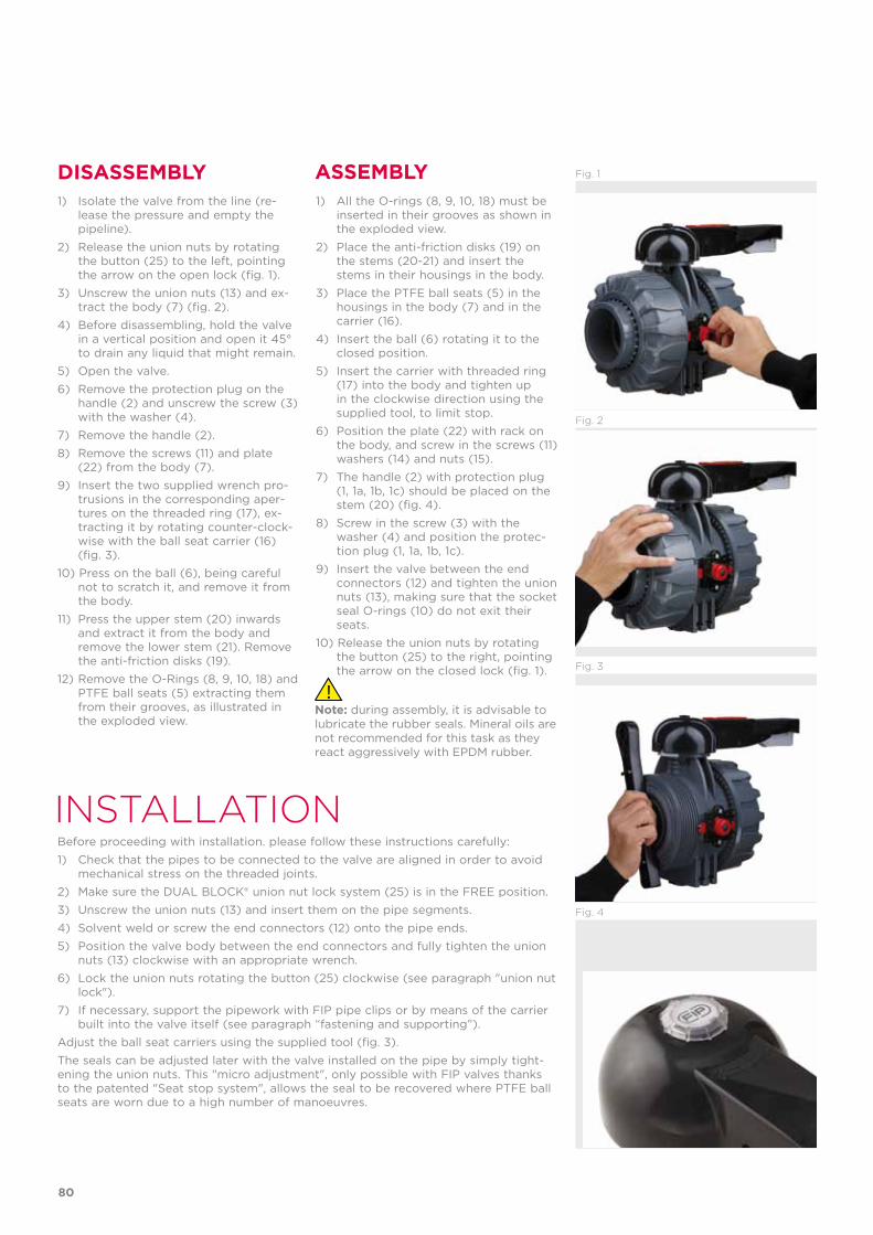
2) Release the union nuts by rotating the button (25) to the left, pointing the arrow on the open lock (fig. 1).
3) Unscrew the union nuts (13) and ex-tract the body (7) (fig. 2).
4) Before disassembling, hold the valve in a vertical position and open it 45° to drain any liquid that might remain.
5) Open the valve.6) Remove the protection plug on the
handle (2) and unscrew the screw (3) with the washer (4).
7) Remove the handle (2).8) Remove the screws (11) and plate
(22) from the body (7).9) Insert the two supplied wrench pro-
trusions in the corresponding aper-tures on the threaded ring (17), ex-tracting it by rotating counter-clock-wise with the ball seat carrier (16) (fig. 3).
10) Press on the ball (6), being careful not to scratch it, and remove it from the body.
11) Press the upper stem (20) inwards and extract it from the body and remove the lower stem (21). Remove the anti-friction disks (19).
12) Remove the O-Rings (8, 9, 10, 18) and PTFE ball seats (5) extracting them from their grooves, as illustrated in the exploded view.
1) All the O-rings (8, 9, 10, 18) must be inserted in their grooves as shown in the exploded view.
2) Place the anti-friction disks (19) on the stems (20-21) and insert the stems in their housings in the body.
3) Place the PTFE ball seats (5) in the housings in the body (7) and in the carrier (16).
4) Insert the ball (6) rotating it to the closed position.
5) Insert the carrier with threaded ring (17) into the body and tighten up in the clockwise direction using the supplied tool, to limit stop.
6) Position the plate (22) with rack on the body, and screw in the screws (11) washers (14) and nuts (15).
7) The handle (2) with protection plug (1, 1a, 1b, 1c) should be placed on the stem (20) (fig. 4).
8) Screw in the screw (3) with the washer (4) and position the protec-tion plug (1, 1a, 1b, 1c).
9) Insert the valve between the end connectors (12) and tighten the union nuts (13), making sure that the socket seal O-rings (10) do not exit their seats.
10) Release the union nuts by rotating the button (25) to the right, pointing the arrow on the closed lock (fig. 1).
Note: during assembly, it is advisable to lubricate the rubber seals. Mineral oils are not recommended for this task as they react aggressively with EPDM rubber.
Fig. 3
Fig. 4
Fig. 2
Fig. 1
80
wARNINGS- If volatile liquid such as Hydrogen Peroxide (H2O2) or Sodium Hypochlorite
(NaCIO) are used, for safety reasons we recommend you contact the service centre. These liquids, upon vaporising, could create hazardous over pressures in the area between the body and ball.
- Always avoid sudden closing operations and protect the valve from accidental op-erations.
uNIoN NuT loCk
HANDle BloCk
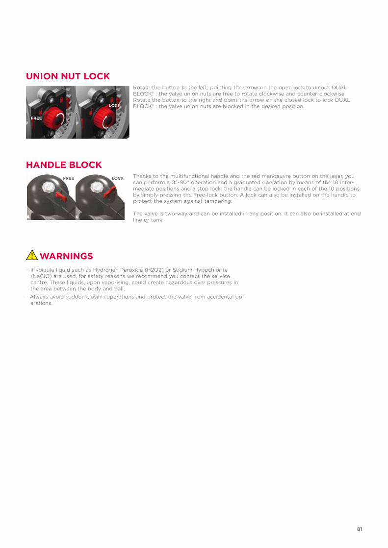
Rotate the button to the left, pointing the arrow on the open lock to unlock DUAL BLOCK® : the valve union nuts are free to rotate clockwise and counter-clockwise.Rotate the button to the right and point the arrow on the closed lock to lock DUAL BLOCK® : the valve union nuts are blocked in the desired position.
Thanks to the multifunctional handle and the red manoeuvre button on the lever, you can perform a 0°-90° operation and a graduated operation by means of the 10 inter-mediate positions and a stop lock: the handle can be locked in each of the 10 positions by simply pressing the Free-lock button. A lock can also be installed on the handle to protect the system against tampering.
The valve is two-way and can be installed in any position. It can also be installed at end line or tank.
FRee
loCk
FRee loCk
81