Embed Size (px)
Citation preview

Installation and serviceinstructionsfor contractors
VIESMANN
Electronic temperature differential control unitVitosolic 200Type SD4
For applicability, see the last page
VITOSOLIC 200
5414 620 GB 6/2009 Please keep safe.

2
Please follow these safety instructions closely to prevent accidents and mate-rial losses.
Safety instructions explained
DangerThis symbol warns against therisk of injury.
! Please noteThis symbol warns against therisk of material losses and envi-ronmental pollution.
NoteDetails identified by the word "Note" con-tain additional information.
Target group
These instructions are exclusivelydesigned for qualified personnel.■ Work on electrical equipment must
only be carried out by a qualified elec-trician.
■ The system must be commissioned bythe system installer or a qualified per-son authorised by the installer.
Regulations
Observe the following when working onthis system ■ all legal instructions regarding the pre-
vention of accidents,■ all legal instructions regarding envi-
ronmental protection,■ the Code of Practice of relevant trade
associations.■ all current safety regulations as
defined by DIN, EN, DVGW, VDE andall locally applicable standards
Working on the system
■ Isolate the system from the power sup-ply and check that it is no longer 'live',e.g. by removing a separate fuse or bymeans of a main isolator.
■ Safeguard the system against unau-thorised reconnection.
! Please noteElectronic modules can be dam-aged by electrostatic dis-charges.Touch earthed objects, such asheating or water pipes, to dis-charge static loads.
Repair work
! Please noteRepairing components that fulfil asafety function can compromisethe safe operation of your heatingsystem.Replace faulty components onlywith original Viessmann spareparts.
Safety instructions
Safety instructions
5414
620
GB

3
Ancillary components, spare andwearing parts
! Please noteSpare and wearing parts thathave not been tested togetherwith the heating system can com-promise its function. Installingnon-authorised components andnon-approved modifications orconversions can compromisesafety and may invalidate ourwarranty.For replacements, use only orig-inal spare parts supplied orapproved by Viessmann.
Safety instructions
Safety instructions (cont.)
5414
620
GB
4
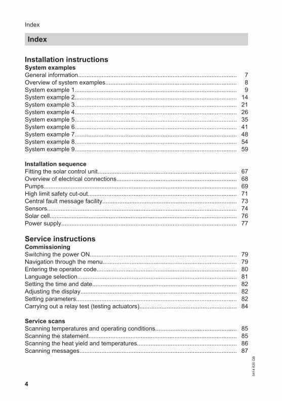
Installation instructionsSystem examplesGeneral information.............................................................................................. 7Overview of system examples.............................................................................. 8System example 1................................................................................................ 9System example 2................................................................................................ 14System example 3................................................................................................ 21System example 4................................................................................................ 26System example 5................................................................................................ 35System example 6................................................................................................ 41System example 7................................................................................................ 48System example 8................................................................................................ 54System example 9................................................................................................ 59
Installation sequenceFitting the solar control unit.................................................................................. 67Overview of electrical connections....................................................................... 68Pumps.................................................................................................................. 69High limit safety cut-out........................................................................................ 71Central fault message facility............................................................................... 73Sensors................................................................................................................ 74Solar cell............................................................................................................... 76Power supply........................................................................................................ 77
Service instructionsCommissioningSwitching the power ON....................................................................................... 79Navigation through the menu............................................................................... 79Entering the operator code................................................................................... 80Language selection.............................................................................................. 81Setting the time and date..................................................................................... 82Adjusting the display............................................................................................ 82Setting parameters............................................................................................... 82Carrying out a relay test (testing actuators)......................................................... 84
Service scansScanning temperatures and operating conditions................................................ 85Scanning the statement........................................................................................ 85Scanning the heat yield and temperatures........................................................... 86Scanning messages............................................................................................. 87
Index
Index
5414
620
GB

5
TroubleshootingFault messages.................................................................................................... 88Checking sensors................................................................................................. 92Checking relays (actuators).................................................................................. 92Changing the fuse................................................................................................ 93
Function descriptionSystems................................................................................................................ 94Function blocks.................................................................................................... 112Cylinder temperature control................................................................................ 116Cylinder temperature limit.................................................................................... 117Cylinder priority control......................................................................................... 117Collector emergency stop..................................................................................... 118Bypass.................................................................................................................. 118External heat exchanger...................................................................................... 122Cooling function.................................................................................................... 126Interval function.................................................................................................... 127Collector cooling function..................................................................................... 128Reverse cooling function...................................................................................... 129Frost protection function....................................................................................... 129Target temperature............................................................................................... 130Parallel relay......................................................................................................... 130Booster suppression............................................................................................. 131Cylinder 2 (to 4) ON............................................................................................. 134Utilisation of excess heat...................................................................................... 134Minimum collector temperature limit..................................................................... 135Cyclical heating.................................................................................................... 135Additional function for DHW heating.................................................................... 136Cylinder heating................................................................................................... 138Speed control....................................................................................................... 139Central fault message — signalling relay............................................................. 141Heat statement..................................................................................................... 141SD module............................................................................................................ 145Relay kick............................................................................................................. 147
Parts list.............................................................................................................. 148
Specification....................................................................................................... 149
AppendixMenu structure overview...................................................................................... 150Overview of system parameters........................................................................... 151PCBs.................................................................................................................... 166
Index
Index54
14 6
20 G
B

6
CertificatesDeclaration of conformity...................................................................................... 168
Keyword index.................................................................................................... 169
Index
Index (cont.)
5414
620
GB

7
Anti-scalding protection
DangerSubject to system configuration,DHW temperatures above 60 °Ccan occur. DHW with tempera-tures in excess of 60 °C can resultin scalding.
To limit the temperature to 60 °C,install mixing equipment, e.g. athermostatically controlled mix-ing valve (accessory). Install amixer tap as anti-scalding deviceat the draw-off point.
Equipotential bonding and lightning protection of the solar ther-mal system
Install an electrical conductor on thepipework system of the solar circuit in thelower part of the building in compliancewith VDE or local regulations.
The connection of the collector system toa new or existing lightning protectionsystem or the provision of local earthingmust only be carried out by authorisedtrained personnel, who must take intoaccount the conditions applicable onsite.
Additional function for DHW heating
DVGW W 551 specifies that the totalwater content is maintained at 60 ºC andthe pre-heat stages must be heated onceevery day to 60 ºC.■ Systems with a cylinder capacity, incl.
preheat stage, in excess of 400 litres■ Systems with a line content in excess
of 3 l from the DHW cylinder to thedraw-off point
We recommend heating up in late after-noon. This ensures that the lower cylin-der area or the pre-heating stage is coldagain following the expected drawings(evenings and the following morning)and can subsequently be heated upagain by solar energy.
NoteFor detached houses and two-familyhomes, this heat up is recommended,but not compulsory.
System examples
General information54
14 6
20 G
B
Inst
alla
tion

8
System example 1, see page 9.
M
System example 4, see page 26.
M
System example 2, see page 14.
M
M
System example 5, see page 35.
M
M
System example 3, see page 21.
M
System example 6, see page 41.
M
M
System examples
Overview of system examples
5414
620
GB

9
System example 7, see page 48.
M
M
System example 9, see page 59.
M
M
System example 8, see page 54.
M
System example 1
DHW heating with dual-mode DHW cylinder
Main components
■ Viessmann solar collectors■ DHW cylinders Vitocell 100-B or
Vitocell 300-B■ Vitosolic 200■ Solar-Divicon■ Wall mounted oil/gas boiler or oil/gas
boiler
Function description
DHW heating with solar energy
Solar circuit pump R1 eE starts andDHW cylinder qP is heated up if the tem-perature differential between collectortemperature sensor S1 eQ and cylindertemperature sensor S2 qQ exceeds thestart temperature differential ΔT.Solar circuit pump R1 eE is stopped inaccordance with the following criteria:
System examples
Overview of system examples (cont.)
5414
620
GB
Inst
alla
tion

10
■ Actual temperature dropping belowthe stop temperature differential ΔToff
■ Exceeding the electronic temperaturelimit of control unit eZ (max. 90 °C)
■ Reaching the temperature selected athigh limit safety cut-out qW (if installed)
Additional function for DHW heating
The requirements for the additional func-tion are achieved through circulationpump R5 qT.
Suppression of DHW cylinder reheat-ing by the boiler
Coding address "67" in boiler control unit2 defaults a third set DHW temperature(setting range 10 to 95 °C). This valuemust be below the first set DHW temper-ature. DHW cylinder qP will only beheated by boiler 1 (solar circuitpump R1 eE runs) if this set value cannotbe achieved by the solar thermal sys-tem.
DHW heating without solar energy
The upper section of DHW cylinder qP isheated by boiler 1. The cylinder ther-mostat with cylinder temperature sen-sor 3 of boiler control unit 2 regulatescirculation pump for cylinder heating4.
System examples
System example 1 (cont.)
5414
620
GB
11
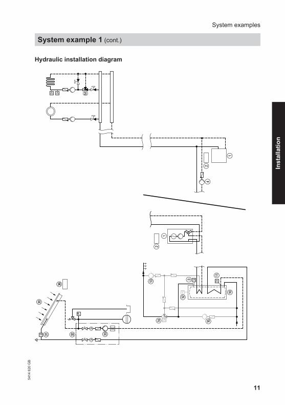
Hydraulic installation diagram
P
M
1
24
1
2
eZ
eP
eW
eQ
qE
qP
eE
qTqR
qW
3
System examples
System example 1 (cont.)
5414
620
GB
Inst
alla
tion

12
Equipment required
Pos. Description1 Wall mounted oil/gas boiler or oil/gas boiler with2 Boiler and heating circuit control unit3 Cylinder temperature sensor4 Circulation pump for cylinder heating
(integrated for wall mounted oil/gas boiler)qP Dual-mode DHW cylinderqQ Cylinder temperature sensor S2 (SOL)qW High limit safety cut-out STBqE DHW circulation pump
(internal/external extension may be required for connecting a wall mountedoil/gas boiler)
qR Automatic thermostatic mixing valveqT Circulation pump R5 (anti-stratification)eP Solar collectorseQ Collector temperature sensor S1 (KOL)eW Solar-DiviconeE Solar circuit pump R1eZ Vitosolic 200eU Junction boxeI ON/OFF switch (on site) AccessoriesuQ Solar celluW Heat meter extension kit (flow meter)uE Large displayuR Datalogger For boiler and heating circuit accessories, see boiler scheme.
System examples
System example 1 (cont.)
5414
620
GB

13
Electrical installation diagram
qT
uQ2
eE
STB
KOL
SOL
eQ2
2
3R1
S1
S2
eU
.
.
.
S12
CS10
Imp 1
Imp 2
V BUS
145
uW2
uE/uR2
2
R2
R3
R4
R5
R7
R6
qW
KM BUS
N,L,PE 230 V / 50 Hz
M
3230
V / 5
0 H
zLo
w v
olta
ge
eZ
3
3
3
M
eI
System examples
System example 1 (cont.)
5414
620
GB
Inst
alla
tion

14
Required settings on the solar control unit
Main menu Deliveredcondition
Setting
Operator code 0000 0200Solar options ■ System (see page 95) 1 1Set solar values ■ Tcylset (set cylinder temperature) 60 °C ■ ΔTon (start temperature differential for solar circuit
pump R1 eE)8.0 K
■ ΔToff (stop temperature differential for solar circuitpump R1 eE)
4.0 K
System options ■ Add. fct.
(Additional function for DHW heating)No Yes
(if a DHW cir-culation pumpis connected)
For pump speed, see page 139.
System example 2
DHW heating with dual-mode DHW cylinder and central heatingbackup with heating water buffer cylinder
Main components
■ Viessmann solar collectors■ DHW cylinders Vitocell 100-B or
Vitocell 300-B■ Heating water buffer cylinder
Vitocell 140-E or Vitocell 160-E■ Vitosolic 200■ Solar-Divicon■ Solar pump line■ Wall mounted oil/gas boiler or oil/gas
boiler
Function description
DHW heating with solar energy
Solar circuit pump R1 eE starts andDHW cylinder qP is heated up if the tem-perature differential between collectortemperature sensor S1 eQ and cylindertemperature sensor S2 qQ exceeds thestart temperature differential ΔT.Solar circuit pump R1 eE is stopped inaccordance with the following criteria:
System examples
System example 1 (cont.)
5414
620
GB

15
■ Actual temperature dropping belowthe stop temperature differential ΔToff
■ Exceeding the electronic temperaturelimit of control unit eZ (max. 90 °C)
■ Reaching the temperature selected athigh limit safety cut-out qW (if installed)
Additional function for DHW heating
The requirements for the additional func-tion are achieved through circulationpump R5 qT.
Suppression of DHW cylinder reheat-ing by the boiler
Coding address "67" in boiler controlunit 2 defaults a third set DHW tem-perature (setting range 10 to 95 °C). Thisvalue must be below the first set DHWtemperature. DHW cylinder qP will onlybe heated by boiler 1 (solar circuitpump R1 eE runs) if this set value cannotbe achieved by the solar thermal sys-tem.
DHW heating without solar energy
The upper section of DHW cylinder qP isheated by boiler 1. The cylinder ther-mostat with cylinder temperature sen-sor 3 of boiler control unit 2 regulatescirculation pump for cylinder heat-ing 4.
Central heating with solar energy
Circulation pump R4 eT is started to heatheating water buffer cylinder rP if theDHW cylinder qP cannot be heated andthe temperature differential between col-lector temperature sensor S1 eQ andbuffer cylinder temperature sensor S4rQ is greater than start temperature dif-ferential ΔT2on. The pump will stop if theactual temperature falls below the stoptemperature differential ΔT2off or it rea-ches the set buffer cylinder temperatureTcyl2set.The temperature inside heating waterbuffer cylinder rP will be limited by theelectronic temperature limiter or highlimit safety cut-out rR (if required).Circulation pump R4 eT is stoppedroughly every 15 min for approx. 2 min,(times adjustable), to check whether thetemperature at collector temperaturesensor S1 eQ is high enough to changeover to DHW cylinder heating qP.Three-way diverter valve R6 rZ isswitched to position "AB-A" and the heat-ing return water is routed to boiler 1 viaheating water buffer cylinder rP, if thetemperature differential between buffercylinder temperature sensor S5 rE andheating circuit return temperature sen-sor S6 rT exceeds start temperature dif-ferential ΔT6on. If the temperature of thepreheated return water is too low, boiler1 reheats the water to the required flowtemperature. Three-way diverter valveR6 rZ is switched to position "AB-B" ifthe actual temperature falls below thestop temperature differential ΔT6off.
System examples
System example 2 (cont.)
5414
620
GB
Inst
alla
tion

16
Central heating without solar energy
Three-way diverter valve R6 rZ remainsat zero volt (position "AB-B") if the tem-perature differential between buffer cyl-inder temperature sensor S5 rE andheating circuit return temperature sensorS6 rT is less than temperature differen-tial ΔT6off. There will be no flow throughheating water buffer cylinder rP.
Boiler 1 supplies the heating circuitwith heat according to the heating curveset at boiler control unit 2.A low loss header 6 with flow temper-ature sensor 5 is required in conjunc-tion with a wall mounted oil/gasboiler.
System examples
System example 2 (cont.)
5414
620
GB
17
Hydraulic installation diagram
P
HV2
HV3
/HR
1
HR
3H
R4
HV1
HR
2
M
MB
AAB
eZ
eP
eW
eQ
rP
3
qP
eE
qTqR
qW
1
1
2
eT
eR
qE
6
rQ
rE
rR
5
2
rZ
rT
4
System examples
System example 2 (cont.)
5414
620
GB
Inst
alla
tion
18
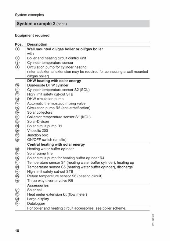
Equipment required
Pos. Description1 Wall mounted oil/gas boiler or oil/gas boiler with2 Boiler and heating circuit control unit3 Cylinder temperature sensor4 Circulation pump for cylinder heating
(internal/external extension may be required for connecting a wall mountedoil/gas boiler)
DHW heating with solar energyqP Dual-mode DHW cylinderqQ Cylinder temperature sensor S2 (SOL)qW High limit safety cut-out STBqE DHW circulation pumpqR Automatic thermostatic mixing valveqT Circulation pump R5 (anti-stratification)eP Solar collectorseQ Collector temperature sensor S1 (KOL)eW Solar-DiviconeE Solar circuit pump R1eZ Vitosolic 200eU Junction boxeI ON/OFF switch (on site) Central heating with solar energyrP Heating water buffer cylindereR Solar pump lineeT Solar circuit pump for heating buffer cylinder R4rQ Temperature sensor S4 (heating water buffer cylinder), heating uprE Temperature sensor S5 (heating water buffer cylinder), dischargerR High limit safety cut-out STBrT Return temperature sensor S6 (heating circuit)rZ Three-way diverter valve R6 AccessoriesuQ Solar celluW Heat meter extension kit (flow meter)uE Large displayuR Datalogger For boiler and heating circuit accessories, see boiler scheme.
System examples
System example 2 (cont.)
5414
620
GB

19
Electrical installation diagram
2rQ
STBrR3
rZM3
uW2
qT
uQ2
eE
STB
KOL
SOL
eQ2
2
3R1
S1
S2
eU
.
.
.
S12
CS10
Imp 1
Imp 2
V BUS
145
uW2
uE/uR2
2
R2
R3
R4
R5
R7
R6
qW
KM BUS
N,L,PE 230 V / 50 Hz
S3
S42
S5 rE2
S6 rT
M
3230
V / 5
0 H
zLo
w v
olta
ge
eZ
M
M eT3
3
3
3
eU
eI
System examples
System example 2 (cont.)
5414
620
GB
Inst
alla
tion

20
Required settings on the solar control unit
Main menu Deliveredcondition
Setting
Operator code 0000 0200Solar options ■ System (see page 99) 1 3■ Hyd. Type (see page 99) 1 2Set solar values ■ Tcylset (set cylinder temperature) 60 °C ■ Tcyl2set (set buffer cylinder temperature) 60 °C ■ ΔTon (start temperature differential for solar cir-
cuit pump R1 eE)8.0 K
■ ΔToff (stop temperature differential for solar cir-cuit pump R1 eE)
4.0 K
■ ΔT2on (start temperature differential for solar cir-cuit pump for buffer cylinder heating R4 eT)
8.0 K
■ ΔT2off (stop temperature differential for solar cir-cuit pump for buffer cylinder heating R4 eT)
4.0 K
■ Priority Cyl1 1 ■ Priority Cyl2 2 Solar contractor ■ t-stop (duration of the pump runtime interruption) 2 minutes ■ t-circ. (break intervals) 15 minutes ■ ΔT Col
During the t-stop time the collector temperaturemust rise by the value of ΔT Col to change overto heating the consumer with priority 1.
2 K
System options ■ Add. fct.
(Additional function for DHW heating)No Yes
(if a DHW circu-lation pump isconnected)
■ ΔT Fct6 (ΔT function for switching the three-waydiverter valve R6 rZ, function block 2, seepage 112)
No Yes
Set system values ■ ΔT6on (start temperature differential for R6) 5.0 K ■ ΔT6off (stop temperature differential for R6) 3.0 K
For pump speed, see page 139.
System examples
System example 2 (cont.)
5414
620
GB

21
In conjunction with a wall mounted oil/gas boiler
Codes required at the boiler and heating circuit control unitCode Function53:3 System without DHW circulation pump:
The circulation pump for cylinder heating 4 is connected tooutput sK of internal extension H1 or H2
5b:1 Internal diverter valve without function(DHW cylinder connected downstream of the low lossheader)
System example 3
DHW heating with two mono-mode DHW cylinders
Main components
■ Viessmann solar collectors■ 2 DHW cylinders Vitocell 100-V or
Vitocell 300-V■ Vitosolic 200■ Solar-Divicon■ Wall mounted oil/gas boiler or oil/gas
boiler
Function description
DHW heating with solar energy
Solar circuit pump R1 eE is switched onand DHW cylinder 1 qP is heated up ifthe temperature differential between col-lector temperature sensor S1 eQ andcylinder temperature sensor S2 qQ isgreater than the start temperature differ-ential ΔTon.Solar circuit pump R1 eE is stopped inaccordance with the following criteria:
■ Actual temperature dropping belowthe stop temperature differential ΔToff
■ Exceeding the electronic temperaturelimit of control unit eZ (max. 90 °C)
■ Reaching the temperature selected athigh limit safety cut-out qW (if installed)
Transfer pump R5/R6 qT is started inaccordance with the following criteria:■ The temperature differential between
sensor S5 qZ and sensor S6 qU isgreater than start temperature differ-ential ΔT6on
■ Additional function for DHW heating isenabled
The water heated in DHW cylinder 1 qPis transferred to DHW cylinder 2 qI. Thisway, DHW cylinder 2 qI is also heatedby solar energy.Transfer pump R5/R6 qT stops when theactual temperature falls below stop tem-perature differential ΔT6off or if the addi-tional function stops.DHW circulation pump qE (if installed)for DHW cylinder 2 qI is controlled byboiler control unit 2.
System examples
System example 2 (cont.)
5414
620
GB
Inst
alla
tion

22
Suppression of DHW cylinder reheat-ing by the boiler
Coding address "67" in boiler control unit2 defaults a third set DHW temperature(setting range 10 to 95 °C). This valuemust be below the first set DHW temper-ature. DHW cylinder 2 qI will only beheated by boiler 1 (solar circuitpump R1 eE runs) if this set value cannotbe achieved by the solar thermal sys-tem.
DHW heating without solar energy
DHW cylinder 2 qI is heated by boiler1. The cylinder thermostat with cylindertemperature sensor 3 of boiler controlunit 2 regulates circulation pump forcylinder heating 4.
System examples
System example 3 (cont.)
5414
620
GB

23
Hydraulic installation diagram
M
P
21
1
1
2
qE
qI
qR
eZ
eP
eW
eQ
qP
eE
qW
qT qZ
qU
2
34
System examples
System example 3 (cont.)
5414
620
GB
Inst
alla
tion

24
Equipment required
Pos. Description1 Wall mounted oil/gas boiler or oil/gas boiler with2 Boiler and heating circuit control unit3 Cylinder temperature sensor4 Circulation pump for cylinder heating
(integrated for wall mounted oil/gas boiler)qI DHW cylinder 2, mono-modeqP DHW cylinder 1, mono-modeqQ Cylinder temperature sensor S2 (SOL)qW High limit safety cut-out STBqE DHW circulation pump
(internal/external extension may be required for connecting a wall mountedoil/gas boiler)
qR Automatic thermostatic mixing valveeP Solar collectorseQ Collector temperature sensor S1 (KOL)eW Solar-DiviconeE Solar circuit pump R1eZ Vitosolic 200eU Junction boxeI ON/OFF switch (on site) DHW circulation diversionqT Circulation pump R5/R6 (anti-stratification)qZ Temperature sensor S5 (DHW cylinder 1)qU Temperature sensor S6 (DHW cylinder 2) AccessoriesuQ Solar celluW Heat meter extension kit (flow meter)uE Large displayuR Datalogger For boiler and heating circuit accessories, see boiler scheme.
System examples
System example 3 (cont.)
5414
620
GB

25
Electrical installation diagram
uW2
qT
uQ
2
eE
STB
KOL
SOL
eQ
3
2
2
3R1
S1
S2
eU
.
.
.CS10
Imp 1
Imp 2
V BUS
145
uW2
uE/uR2
2
R2
R3
R4
R5
R7
R6
qW
KM BUS
N,L,PE 230 V / 50 Hz3
S3
S42
S5 qZ2
S6 qU
3M
3230
V / 5
0 H
zLo
w v
olta
ge
eZ
M
eI
A
A Insert the jumper between R5 andR6.
System examples
System example 3 (cont.)
5414
620
GB
Inst
alla
tion

26
Required settings on the solar control unit
Main menu Deliveredcondition
Setting
Operator code 0000 0200Solar options ■ System (see page 95) 1 1Set solar values ■ Tcylset (set cylinder temperature) 60 °C ■ ΔTon (start temperature differential for solar cir-
cuit pump R1 eE)8.0 K
■ ΔToff (stop temperature differential for solar cir-cuit pump R1 eE)
4.0 K
System options ■ Add. fct.
(Additional function for DHW heating)No Yes
■ ΔT Fct6 (ΔT function for switching the circulationpump R6 qT, function block 2, see page 112)
No Yes
Set system values ■ ΔT6on (start temperature differential for R6) 5.0 K ■ ΔT6off (stop temperature differential for R6) 3.0 K
For pump speed, see page 139.
System example 4
DHW and swimming pool water heating with dual-mode DHWcylinder
Main components
■ Viessmann solar collectors■ DHW cylinders Vitocell 100-B or
Vitocell 300-B■ Swimming pool■ 2 heat exchangers for swimming pool
water■ Vitosolic 200■ Solar-Divicon
■ Solar pump line■ Wall mounted oil/gas boiler or oil/gas
boiler
System examples
System example 3 (cont.)
5414
620
GB

27
Function description
DHW heating with solar energy
Solar circuit pump R1 eE starts andDHW cylinder qP is heated up if the tem-perature differential between collectortemperature sensor S1 eQ and cylindertemperature sensor S2 qQ is greaterthan the start temperature differentialΔTon.Solar circuit pump R1 eE is stopped inaccordance with the following criteria:■ Actual temperature dropping below
the stop temperature differential ΔToff■ Exceeding the electronic temperature
limit of control unit eZ (max. 90 °C)■ Reaching the temperature selected at
high limit safety cut-out qW (if installed)
Additional function for DHW heating
The requirements for the additional func-tion are achieved through circulationpump R5 qT.
Suppression of DHW cylinder reheat-ing by the boiler
Coding address "67" in boiler controlunit 2 defaults a third set DHW tem-perature (setting range 10 to 95 °C). Thisvalue must be below the first set DHWtemperature. DHW cylinder qP will onlybe heated by boiler 1 (solar circuitpump R1 eE runs) if this set value cannotbe achieved by the solar thermal sys-tem.
DHW heating without solar energy
The upper section of DHW cylinder qPis heated by boiler 1. The cylinder ther-mostat with cylinder temperature sen-sor 3 of boiler control unit 2 regulatescirculation pump for cylinder heat-ing 4.
Swimming pool water heating bysolar energy
If the DHW cylinder qP cannot continueto be heated, the system checks whetherthe swimming pool tP can be heated.Circulation pump R4 eT starts if the tem-perature differential between collectortemperature sensor S1 eQ and temper-ature sensor S4 tW is greater than starttemperature differential ΔT2on. Thepump stops if the actual temperaturefalls below the stop temperature differ-ential ΔT2off or if the set swimming pooltemperature Tcyl2set has beenreached.Circulation pump R4 eT is stoppedroughly every 30 minutes for approx.7 minutes (times adjustable), to checkwhether the temperature at collectortemperature sensor S1 eQ is highenough to change over to DHW cylinderheating qP.The circulation pump for heating swim-ming pool water R3 tE starts if the tem-perature differential between tempera-ture sensor S3 tT and temperature sen-sor S4 tW is greater than start tempera-ture differential ΔT5on and start temper-ature differential Th2on has not beenreached. The pump stops if the actualtemperature falls below the stop temper-ature differential ΔT5off or if the stoptemperature Th2off has been reached.
System examples
System example 4 (cont.)
5414
620
GB
Inst
alla
tion

28
Swimming pool water heating byboiler:If the solar energy is inadequate to heatthe swimming pool water, it will beheated by boiler 1 via temperature sen-sor S5 tU on heat exchanger 2 tZ.Circulation pump R6 zP and filterpump tI start when the start tempera-ture Th3on and has not been reachedduring the time set via time switch 2. Thepumps stop when the stop temperatureTh3off has been reached or if the timeframe is exceeded.
Filter time and possible reheating by theboiler 1:■ outside the times during which heating
by solar energy can be expected■ outside the times when central heating
and DHW heating are required
System examples
System example 4 (cont.)
5414
620
GB

29
Hydraulic installation diagram
P
M
12
eZ
eP
eW
eQ
qE 3
qP
eE
qTqR
qW
1
2tW
eT
eR
tP
tI
tQtZ
tR
tU
tO
tE
tTzP
4
System examples
System example 4 (cont.)
5414
620
GB
Inst
alla
tion

30
Equipment required
Pos. Description1 Wall mounted oil/gas boiler or oil/gas boiler with2 Boiler and heating circuit control unit3 Cylinder temperature sensor4 Circulation pump for cylinder heating
(integrated for wall mounted oil/gas boiler)qP Dual-mode DHW cylinderqQ Cylinder temperature sensor S2 (SOL)qW High limit safety cut-out STBqE DHW circulation pump
(internal/external extension may be required for connecting a wall mountedoil/gas boiler)
qR Automatic thermostatic mixing valveqT Circulation pump R5 (anti-stratification)eP Solar collectorseQ Collector temperature sensor S1 (KOL)eW Solar-DiviconeE Solar circuit pump R1eZ Vitosolic 200eU Junction boxeI ON/OFF switch (on site)eO Contactor relay Swimming pool water heating by solar energytP Swimming pooltQ Heat exchanger 1tW Temperature sensor S4 (swimming pool)tT Temperature sensor S3 (heat exchanger 1)eR Solar pump lineeT Solar circuit pump for swimming pool water heating R4tE Circulation pump for swimming pool water heating R3tR Temperature limiter (maximum limit) Swimming pool water heating by oil/gas boilertZ Heat exchanger 2tU Temperature sensor S5 (heat exchanger 2)tO Temperature limiter (maximum limit)zP Circulation pump for swimming pool water heating R6 (reheating)zQ Control module V
(in conjunction with Vitotronic 200, types KW1, KW2, KW4, KW5 andVitotronic 300, type KW3 for boiler with two-stage and modulating burner)
System examples
System example 4 (cont.)
5414
620
GB

31
Pos. DescriptiontI Filter pump AccessoriesuQ Solar celluW Heat meter extension kit (flow meter)uE Large displayuR Datalogger For boiler and heating circuit accessories, see boiler scheme.
System examples
System example 4 (cont.)
5414
620
GB
Inst
alla
tion

32
Electrical installation diagram
uW2
2tT
2tW
uQ2
KOLSOL
eQ2
2S1
S2
...CS10
Imp 1
Imp 2
V BUS145
uW2
uE/uR2
2
KM BUS
S3
S42
S5 tUS6
Low
vol
tage
R7-AR7-MR7-R
R629
NR530
?
R431R332R233R134
NL 35
?
eZ
AB
M1~
zP
eO
tO
tE
eO
tR
eT
qW
eE
eU
M1~
M1~
M1~
230 V / 50 Hz
eI
M1~ qT
230
V / 5
0 H
z
A, B See the following page.
System examples
System example 4 (cont.)
5414
620
GB

33
A Start signal for filter pump tIB External burner start in conjunction
with the following control units:Vitotronic 200, types KW1, KW2, KW4,KW5, Vitotronic 300, type KW3:Connection in plug "X12"orConnection in plug aBÖ at terminals"ON", "ON/TR"orin socket "DE4" in control module V zQin plug a-D at terminals "1" and "2"(Set the minimum set boiler water tem-perature via coding address "32" at theboiler circuit control unit)Vitotronic 200, type GW1, GW2:Connection in plug aVH at terminals "2"and "3"
(Set the minimum set boiler water tem-perature via coding address "9b" at theboiler circuit control unit)Vitotronic 200, type KW6:Connection in plug aVD at terminals "1"and "2"(Set the minimum set boiler water tem-perature via coding address "9b" at theboiler circuit control unit)Vitotronic 200, type HO1/HO1A:Connection in external extension H1, inplug aVD at terminals "1" and "2"(Set the minimum set boiler water tem-perature via coding address "9b" at theboiler circuit control unit)
Required settings on the solar control unit
Main menu Deliveredcondition
Setting
Operator code 0000 0200Solar options ■ System (see page 99) 1 3■ Hyd. Type (see page 99) 1 2Set solar values ■ Tcylset (set cylinder temperature) 60 °C ■ Tcyl2set (set swimming pool temperature) 60 °C 28 °C■ ΔTon (start temperature differential for solar cir-
cuit pump R1 eE)8.0 K
■ ΔToff (stop temperature differential for solar cir-cuit pump R1 eE)
4.0 K
■ ΔT2on (start temperature differential for solar cir-cuit pump for swimming pool water heating R4eT)
8.0 K
■ ΔT2off (stop temperature differential for solar cir-cuit pump for swimming pool water heating R4eT)
4.0 K
■ Priority Cyl1 1 ■ Priority Cyl2 (swimming pool) 2
System examples
System example 4 (cont.)
5414
620
GB
Inst
alla
tion

34
Main menu Deliveredcondition
Setting
Solar contractor ■ t-stop (duration of the pump runtime interruption) 2 minutes 7 minutes■ t-circ. (break intervals) 15 minutes 30 minutes■ ΔT Col
During the t-stop time the collector temperaturemust rise by the value of ΔT Col to change overto heating the consumer with priority 1.
2 K
System options ■ Add. fct.
(Additional function for DHW heating)No Yes
(if a DHW circu-lation pump isconnected)
■ Thermost. 2 (S4)(Thermostat function for maximum temperaturestop of circulation pump R3 tE, function block 1,see page 112)
No Yes
■ ΔT Fct5 (ΔT function for switching the circulationpump R3 tE, function block 1, see page 112)
No Yes
■ Thermost. 3 (S5)(Thermostat function for swimming pool waterheating by the boiler,for switching circulation pump R6 zP, functionblock 2, see page 112)
No Yes
■ Time switch 2*1 No YesSet system values ■ Th2on (start temperature for R3) 40 °C Tcyl2set−0.5 K■ Th2off (stop temperature for R3) 45 °C Tcylset*2■ ΔT5on (start temperature differential for R3) 5.0 K ■ ΔT5off (stop temperature differential for R3) 3.0 K ■ Th3on (start temperature for R6 and tI) 40 °C 26.5 °C■ Th3off (stop temperature for R6 and tI) 45 °C Th3on + 0.5 K
For pump speed, see page 139. For the solar circuit pump for swimmingpool water heating R4 eT, parameter"Control" must not be set to "Pulse"(see page 140).
*1 Setting the times, see page 159.*2 Possibly set a value 1 to 2 K higher. For this, observe that the relative humidity will
increase in indoor swimming pools.
System examples
System example 4 (cont.)
5414
620
GB

35
DHW heating and central heating backup with a multi-mode heat-ing water buffer cylinder
Main components
■ Viessmann solar collectors■ Vitocell 340-M or Vitocell 360-M multi-
mode heating water buffer cylinderwith integral DHW heating, with orwithout stratification system
■ Vitosolic 200■ Solar-Divicon■ Wall mounted oil/gas boiler or oil/gas
boiler
Function description
DHW heating with solar energy
Solar circuit pump R1 eE starts andheating water buffer cylinder qP isheated up if the temperature differentialbetween collector temperature sensorS1 eQ and cylinder temperature sensorS2 qQ is greater than the start tempera-ture differential ΔTon.Solar circuit pump R1 eE is stopped inaccordance with the following criteria:■ Actual temperature dropping below
the stop temperature differential ΔToff■ Exceeding the electronic temperature
limit of control unit eZ (max. 90 °C)■ Reaching the temperature selected at
high limit safety cut-out qW (if installed)Entire heating water buffer cylinder qP isheated by the solar thermal system if theinsolation is adequate.The upper part of heating water buffercylinder qP will only be reheated byboiler 1 if the actual water temperaturefalls below the set temperature selectedat boiler control unit 2.
If the solar energy is inadequate to coverthe entire heat demand, the DHW in thelower part of heating water buffer cylin-der qP will be preheated by solar energy.The DHW in the upper part of the cylin-der is heated to the required temperatureby boiler 1.
Suppression of DHW cylinder reheat-ing by the boiler
Coding address "67" in boiler controlunit 2 defaults a third set DHW tem-perature (setting range 10 to 95 °C). Thisvalue must be below the first set DHWtemperature. The DHW cylinder will onlybe heated by the boiler (solar circuitpump R1 eE runs) if this set value cannotbe achieved by the solar thermal sys-tem.
DHW heating without solar energy
The upper area of heating water buffercylinder qP is heated by boiler 1. Theintegral instantaneous water heater/standby section is heated by the sur-rounding buffer cylinder water.The cylinder thermostat with cylindertemperature sensor 3 of boiler controlunit 2 regulates circulation pump forcylinder heating 4.
System examples
System example 554
14 6
20 G
B
Inst
alla
tion

36
Central heating with solar energy
Three-way diverter valve R6 rZ isswitched to position "AB-A" if the tem-perature differential between buffer cyl-inder temperature sensor S5 qZ andheating circuit return temperature sensorS6 rT is greater than start temperaturedifferential ΔT6on. The heating returnwater is fed to boiler 1 via heating waterbuffer cylinder qP.If the temperature of the preheatedreturn water is too low, boiler 1 reheatsthe water to the required flow tempera-ture. Three-way diverter valve R6 rZ isswitched to position "AB-B" if the actualtemperature falls below stop tempera-ture differential ΔT6off.
Central heating without solar energy
Three-way diverter valve R6 rZ remainsat zero volt (position "AB-B") if the tem-perature differential between buffer cyl-inder temperature sensor S5 qZ andheating circuit return temperature sensorS6 rT is less than stop temperature dif-ferential ΔT6off. There will be no flowthrough heating water buffer cylinderqP.Boiler 1 supplies the heating circuitwith heat according to the heating curveset at boiler control unit 2.A low loss header 6 with flow temper-ature sensor 5 is required in conjunc-tion with a wall mounted oil/gasboiler.
System examples
System example 5 (cont.)
5414
620
GB

37
Hydraulic installation diagram
BAAB
M
P
HV2
/HR
1
HR
2
HV1 HR
3
M
eZ
eP
eW
eQ eE
qW
qR
qE
qP
rZ
qZ
wW
3
4
1
2
1
65
2
rT
System examples
System example 5 (cont.)
5414
620
GB
Inst
alla
tion

38
Equipment required
Pos. Description1 Wall mounted oil/gas boiler or oil/gas boiler with2 Boiler and heating circuit control unit3 Cylinder temperature sensor4 Circulation pump for cylinder heating
(internal/external extension may be required for connecting a wall mountedoil/gas boiler)
qP Heating water buffer cylinder withwW DHW circulation (integral) DHW heating with solar energyqQ Cylinder temperature sensor S2 (SOL)qW High limit safety cut-out STBqE DHW circulation pumpqR Automatic thermostatic mixing valveeP Solar collectorseQ Collector temperature sensor S1 (KOL)eW Solar-DiviconeE Solar circuit pump R1eZ Vitosolic 200eU Junction boxeI ON/OFF switch (on site) Central heating with solar energyqZ Temperature sensor S5 (heating water buffer cylinder)rT Return temperature sensor S6 (heating circuit)rZ Three-way diverter valve R6 AccessoriesuQ Solar celluW Heat meter extension kit (flow meter)uE Large displayuR Datalogger For boiler and heating circuit accessories, see boiler scheme.
System examples
System example 5 (cont.)
5414
620
GB

39
Electrical installation diagram
rZM
uQ2
eE
STB
KOL
SOL
eQ
3
2
2
3R1
S1
S2
eU
.
.
.
S12
CS10
Imp 1
Imp 2
V BUS
145
uW2
uE/uR2
2
R2
R3
R4
R5
R7
R6
qW
KM BUS
N,L,PE 230 V / 50 Hz3
S3
S42
S5 qZ2
S6 rT
3M
3
230
V / 5
0 H
zLo
w v
olta
ge
eZ eI
System examples
System example 5 (cont.)
5414
620
GB
Inst
alla
tion

40
Required settings on the solar control unit
Main menu Deliveredcondition
Setting
Operator code 0000 0200Solar options ■ System (see page 95) 1 1Set solar values ■ Tcylset (set cylinder temperature) 60 °C ■ ΔTon (start temperature differential for solar circuit
pump R1 eE)8.0 K
■ ΔToff (stop temperature differential for solar circuitpump R1 eE)
4.0 K
System options ■ ΔT Fct6 (ΔT function for switching the three-way
diverter valve R6 rZ, function block 2, seepage 112)
No Yes
Set system values ■ ΔT6on (start temperature differential for R6) 5.0 K ■ ΔT6off (stop temperature differential for R6) 3.0 K
For pump speed, see page 139.
In conjunction with a wall mounted oil/gas boiler
Codes required at the boiler and heating circuit control unitCode Function53:3 System without DHW circulation pump:
The circulation pump for cylinder heating 4 is connected tooutput sK of internal extension H1 or H2
5b:1 Internal diverter valve without function(DHW cylinder connected downstream of the low lossheader)
System examples
System example 5 (cont.)
5414
620
GB

41
DHW heating with freshwater module and central heating backupwith heating water buffer cylinder
Main components
■ Viessmann solar collectors■ Freshwater module■ Heating water buffer cylinder
Vitocell 140-E or Vitocell 160-E■ Vitosolic 200■ Solar-Divicon■ Wall mounted oil/gas boiler or oil/gas
boiler
Function description
Freshwater module qP heats DHWwhen hot water is drawn. The energysupply to freshwater module qP is pro-vided via heating water buffer cylin-der rP. Buffer cylinder rP is heated bythe solar thermal system or, in the upperarea, by boiler 1.The heated DHW is heated by freshwa-ter module qP according to the instanta-neous water heater principle. An internalpump transports the heating water fromheating water buffer cylinder rP into thefreshwater module qP. This heats theDHW in the heat exchanger of the fresh-water module qP according to the coun-tercurrent principle. This is regulated bythe internal control unit of the freshwatermodule qP.When utilising the freshwater modulewith integral DHW circulation pump, thethree-way diverter valve qQ in conjunc-tion with sensors qE and S4 qW of thefreshwater module can be regulated byits control unit to provide an optimumstratification of the return water into theheating water buffer cylinder rP.
DHW heating with solar energy
Solar circuit pump R1 eE starts andheating water buffer cylinder rP isheated up if the temperature differentialbetween collector temperature sensorS1 eQ and cylinder temperature sensorS2 rQ is greater than the start tempera-ture differential ΔTon.Solar circuit pump R1 eE is stopped inaccordance with the following criteria:■ Actual temperature dropping below
the stop temperature differential ΔToff■ Exceeding the electronic temperature
limit of control unit eZ (max. 90 °C)■ Reaching the temperature selected at
high limit safety cut-out rR (if installed)Entire heating water buffer cylinder rP isheated by the solar thermal system if theinsolation is adequate.The upper part of heating water buffercylinder rP will only be reheated byboiler 1 if the actual water temperaturefalls below the set temperature selectedat boiler control unit 2.
DHW heating without solar energy
The upper area of heating water buffercylinder rP is heated by boiler 1. Thecylinder thermostat with cylinder temper-ature sensor 3 of boiler control unit2 regulates circulation pump for cylin-der heating 4.
System examples
System example 654
14 6
20 G
B
Inst
alla
tion

42
Central heating with solar energy
Three-way diverter valve R6 rZ isswitched to position "AB-A" and the heat-ing return water is routed to boiler 1 viaheating water buffer cylinder rP, if thetemperature differential between buffercylinder temperature sensor S5 rW andheating circuit return temperature sensorS6 rT exceeds start temperature differ-ential ΔT6on. If the temperature of thepreheated return water is too low,boiler 1 reheats the water to therequired flow temperature. Three-waydiverter valve R6 rZ is switched to posi-tion "AB-B" if the actual temperature fallsbelow the stop temperature differentialΔT6off.
Central heating without solar energy
Three-way diverter valve R6 rZ remainsat zero volt (position "AB-B") if the tem-perature differential between buffer cyl-inder temperature sensor S5 rW andheating circuit return temperature sensorS6 rT is less than temperature differen-tial ΔT6off. There will be no flow throughheating water buffer cylinder rP.Boiler 1 supplies the heating circuitwith heat according to the heating curveset at boiler control unit 2.A low loss header 6 with flow temper-ature sensor 5 is required in conjunc-tion with a wall mounted oil/gasboiler.
System examples
System example 6 (cont.)
5414
620
GB

43
Hydraulic installation diagram
P
HV2
HV3
/HR
1
HR
3H
R4
HV1
HR
2
M
AB BA
M
12
qE
ABB
A
rZ
M
rT
eZ
eP
eW
eQ
rP
eE
rQ
rR
rW
4
3
65
1
2
qP
qW
System examples
System example 6 (cont.)
5414
620
GB
Inst
alla
tion

44
Equipment required
Pos. Description1 Wall mounted oil/gas boiler or oil/gas boiler with2 Boiler and heating circuit control unit3 Cylinder temperature sensor4 Circulation pump for cylinder heating
(internal/external extension may be required for connecting a wall mountedoil/gas boiler)
qP Freshwater moduleqQ Three-way diverter valve (accessory for pos. qP)qW Temperature sensor S4 (accessory for pos. qP)qE Temperature sensor S3 (accessory for pos. qP)rP Heating water buffer cylinder DHW heating with solar energyrQ Cylinder temperature sensor S2 (SOL)rR High limit safety cut-out STBeP Solar collectorseQ Collector temperature sensor S1 (KOL)eW Solar-DiviconeE Solar circuit pump R1eZ Vitosolic 200eU Junction boxeI ON/OFF switch (on site) Central heating with solar energyrW Temperature sensor S5 (heating water buffer cylinder)rT Return temperature sensor S6 (heating circuit)rZ Three-way diverter valve R6 AccessoriesuQ Solar celluW Heat meter extension kit (flow meter)uE Large displayuR Datalogger For boiler and heating circuit accessories, see boiler scheme.
System examples
System example 6 (cont.)
5414
620
GB

45
Electrical installation diagram
Vitosolic 200
rZM
uQ2
eE
STB
KOL
SOL
eQ
3
2
2
3R1
S1
S2
eU
.
.
.
S12
CS10
Imp 1
Imp 2
V BUS
145
uW2
uW2
uE/uR2
2
R2
R3
R4
R5
R7
R6
rR
rQ
KM BUS
N,L,PE 230 V / 50 Hz3
S3
S42
S5 rW2
S6 rT
3M
3
230
V / 5
0 H
zLo
w v
olta
ge
eZ eI
System examples
System example 6 (cont.)
5414
620
GB
Inst
alla
tion

46
Control unit, freshwater module
GN
DS1 L N
N
R1
R2
R3
R4
R5-
RR
5-M
R5-
A
S2 S3 S4 S5 S6 S7
?
230 V / 50 HzLN?
M1~
qP
qE qW qQ
Required settings on the solar control unit
Main menu Deliveredcondition
Setting
Operator code 0000 0200Solar options ■ System (see page 95) 1 1Set solar values ■ Tcylset (set cylinder temperature) 60 °C ■ ΔTon (start temperature differential for solar circuit
pump R1 eE)8.0 K
■ ΔToff (stop temperature differential for solar circuitpump R1 eE)
4.0 K
System options ■ ΔT Fct6 (ΔT function for switching the three-way
diverter valve R6 rZ, function block 2, seepage 112)
No Yes
System examples
System example 6 (cont.)
5414
620
GB

47
Main menu Deliveredcondition
Setting
Set system values ■ ΔT6on (start temperature differential for R6) 5.0 K ■ ΔT6off (stop temperature differential for R6) 3.0 K
For pump speed, see page 139.
Required settings at the freshwater module control unit
Main menu Deliveredcondition
Setting
Options ■ Return dist. (return distribution) OFF ONSetting values ■ ΔT-RVon (start temperature differential for return
valve R3 qQ)5.0 K
■ ΔT-RVoff (stop temperature differential for returnvalve R3 qQ)
5.0 K
In conjunction with a wall mounted oil/gas boiler
Codes required at the boiler and heating circuit control unitCode Function53:3 System without DHW circulation pump:
The circulation pump for cylinder heating 4 is connected tooutput sK of internal extension H1 or H2
5b:1 Internal diverter valve without function(DHW cylinder connected downstream of the low lossheader)
System examples
System example 6 (cont.)
5414
620
GB
Inst
alla
tion

48
DHW heating with mono-mode DHW cylinder and central heatingbackup with multi-mode heating water buffer cylinder
Main components
■ Viessmann solar collectors■ DHW cylinder Vitocell 100-V or
Vitocell 300-V■ Multi-mode heating water buffer cylin-
der Vitocell 340-M or Vitocell 360-Mwith integral DHW heating, with orwithout stratification system
■ Vitosolic 200■ Solar-Divicon■ Wall mounted oil/gas boiler or oil/gas
boiler
Function description
DHW heating with solar energy
Solar circuit pump R1 eE starts andheating water buffer cylinder rP isheated up if the temperature differentialbetween collector temperature sensorS1 eQ and cylinder temperature sensorS2 rQ is greater than the start tempera-ture differential ΔTon.Solar circuit pump R1 eE is stopped inaccordance with the following criteria:■ Actual temperature dropping below
the stop temperature differential ΔToff■ Exceeding the electronic temperature
limit of control unit eZ (max. 90 °C)■ Reaching the temperature selected at
high limit safety cut-out rR (if installed)Entire heating water buffer cylinder rP isheated by the solar thermal system if theinsolation is adequate for DHW heating.
If there is inadequate solar energy, theDHW in the lower part of heating waterbuffer cylinder rP is preheated by solarenergy, and heated to the required tem-perature in DHW cylinder qP by boiler1.A temperature-controlled DHW stratifi-cation is not possible.
DHW heating without solar energy
DHW cylinder qP is heated byboiler 1. The cylinder thermostat withcylinder temperature sensor 3 of boilercontrol unit 2 regulates the circulationpump for cylinder heating 4.
Central heating with solar energy
Three-way diverter valve R6 rZ isswitched to position "AB-A" and the heat-ing return water is routed to boiler 1 viaheating water buffer cylinder rP, if thetemperature differential between buffercylinder temperature sensor S5 rW andheating circuit return temperature sensorS6 rT exceeds start temperature differ-ential ΔT6on. If the temperature of thepreheated return water is too low, boiler1 reheats the water to the required flowtemperature. Three-way diverter valveR6 rZ is switched to position "AB-B" ifthe actual temperature falls below thestop temperature differential ΔT6off.
System examples
System example 7
5414
620
GB

49
Central heating without solar energy
Three-way diverter valve R6 rZ remainsat zero volt (position "AB-B") if the tem-perature differential between buffer cyl-inder temperature sensor S5 rW andheating circuit return temperature sensorS6 rT is less than stop temperature dif-ferential ΔT6off. There will be no flowthrough heating water buffer cylinderrP.
Boiler 1 supplies the heating circuitwith heat according to the heating curveset at boiler control unit 2.A low loss header 6 with flow temper-ature sensor 5 is required in conjunc-tion with a wall mounted oil/gasboiler.
System examples
System example 7 (cont.)
5414
620
GB
Inst
alla
tion

50
Hydraulic installation diagramP
M
HV2
/HR
1
HR
2
HV1
HR
3
BA
AB
M
1
2
eZ
eP
eW
eQ
eE
qP
3
rR
rQ
rP
rW
qR
1
65
2rZrT
qE
4
rE
System examples
System example 7 (cont.)
5414
620
GB

51
Equipment required
Pos. Description1 Wall mounted oil/gas boiler or oil/gas boiler with2 Boiler and heating circuit control unit3 Cylinder temperature sensor4 Circulation pump for cylinder heating
(internal/external extension may be required for connecting a wall mountedoil/gas boiler)
qP DHW cylinderrP Heating water buffer cylinder withrE DHW circulation (integral) DHW heating with solar energyrQ Cylinder temperature sensor S2 (SOL)rR High limit safety cut-out STBqE DHW circulation pumpqR Automatic thermostatic mixing valveeP Solar collectorseQ Collector temperature sensor S1 (KOL)eW Solar-DiviconeE Solar circuit pump R1eZ Vitosolic 200eU Junction boxeI ON/OFF switch (on site) Central heating with solar energyrW Temperature sensor S5 (heating water buffer cylinder)rT Return temperature sensor S6 (heating circuit)rZ Three-way diverter valve R6 AccessoriesuQ Solar celluW Heat meter extension kit (flow meter)uE Large displayuR Datalogger For boiler and heating circuit accessories, see boiler scheme.
System examples
System example 7 (cont.)
5414
620
GB
Inst
alla
tion

52
Electrical installation diagram
rZM
uQ2
eE
STB
KOL
SOL
eQ
3
2
2
3R1
S1
S2
eU
.
.
.
S12
CS10
Imp 1
Imp 2
V BUS
145
uW2
uW2
uE/uR2
2
R2
R3
R4
R5
R7
R6
rR
rQ
KM BUS
N,L,PE 230 V / 50 Hz3
S3
S42
S5 rW2
S6 rT
3M
3
230
V / 5
0 H
zLo
w v
olta
ge
eZ eI
System examples
System example 7 (cont.)
5414
620
GB
53
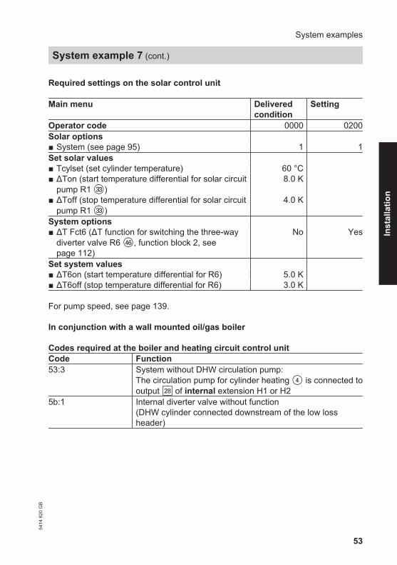
Required settings on the solar control unit
Main menu Deliveredcondition
Setting
Operator code 0000 0200Solar options ■ System (see page 95) 1 1Set solar values ■ Tcylset (set cylinder temperature) 60 °C ■ ΔTon (start temperature differential for solar circuit
pump R1 eE)8.0 K
■ ΔToff (stop temperature differential for solar circuitpump R1 eE)
4.0 K
System options ■ ΔT Fct6 (ΔT function for switching the three-way
diverter valve R6 rZ, function block 2, seepage 112)
No Yes
Set system values ■ ΔT6on (start temperature differential for R6) 5.0 K ■ ΔT6off (stop temperature differential for R6) 3.0 K
For pump speed, see page 139.
In conjunction with a wall mounted oil/gas boiler
Codes required at the boiler and heating circuit control unitCode Function53:3 System without DHW circulation pump:
The circulation pump for cylinder heating 4 is connected tooutput sK of internal extension H1 or H2
5b:1 Internal diverter valve without function(DHW cylinder connected downstream of the low lossheader)
System examples
System example 7 (cont.)
5414
620
GB
Inst
alla
tion

54
Large solar thermal systems for DHW heating
Main components
■ Viessmann solar collectors■ DHW cylinder Vitocell 100-V or
Vitocell 300-V■ Vitocell 100-L preheating cylinder■ Heating water buffer cylinder
Vitocell 140-E or Vitocell 160-E■ Vitosolic 200■ Solar-Divicon■ Wall mounted oil/gas boiler or oil/gas
boiler
Function description
DHW heating with solar energy
Charge circuit
Solar circuit pump R1 eE starts andheating water buffer cylinder rP isheated up if the temperature differentialbetween collector temperature sen-sor S1 eQ and cylinder temperature sen-sor S2 rQ is greater than start tempera-ture differential ΔTon.Solar circuit pump R1 eE is stopped inaccordance with the following criteria:■ Actual temperature dropping below
the stop temperature differential ΔToff■ Exceeding the electronic temperature
limit of control unit eZ (max. 90 °C)■ Reaching the temperature selected at
high limit safety cut-out rE (if installed)Primary pump (preheating cylinder) R6qR and discharge pump (heating waterbuffer cylinder) R3 qI start in accord-ance with the following criteria:
■ The temperature differential betweenbuffer cylinder temperature sensor S5rW and pre-heating cylinder tempera-ture sensor S6 qW is greater than starttemperature differential ΔT6onand
■ The temperature in preheating cylin-der qQ is below the value set at ther-mostatically controlled mixingvalve qO
Discharge circuit
Preheating cylinder qQ is force-filled withcold water. The water in preheating cyl-inder qQ is heated via heatexchanger qU.
Additional function for DHW heating
The requirements for the additional func-tion are achieved through circulationpump R5 qT. Cylinders qP and qQ areheated.
DHW heating without solar energy
DHW cylinder qP is heated by boiler1. The cylinder thermostat with cylindertemperature sensor 3 of boiler controlunit 2 regulates circulation pump forcylinder heating 4. DHW circulationpump qE (if installed) is controlled byboiler control unit 2. Primary pump(preheating cylinder) R6 qR and dis-charge pump (heating water buffer cyl-inder) R6 qI are stopped. The DHW isrouted to DHW cylinder qP via preheat-ing cylinder qQ.
System examples
System example 8
5414
620
GB

55
Hydraulic installation diagram
P
HV2
HV3
/HR
1
HR
3H
R4
HV1
HR
2
MM
qI
qZ
qO
1
2
eZ
eP
eW
eQ
rP
eE
rQ
rW
rE
1
2
qP
qE
qW
qT
34
qRqU
qZ
System examples
System example 8 (cont.)
5414
620
GB
Inst
alla
tion

56
Equipment required
Pos. Description1 Wall mounted oil/gas boiler or oil/gas boiler with2 Boiler and heating circuit control unit3 Cylinder temperature sensor4 Circulation pump for cylinder heating
(integrated for wall mounted oil/gas boiler)qP DHW cylinder DHW heating with solar energyqE DHW circulation pump
(internal/external extension may be required for connecting a wall mountedoil/gas boiler)
qT Circulation pump R5 (anti-stratification)qQ Preheating cylinderqW Temperature sensor S6 (preheating cylinder)qR Primary pump R6 (preheating cylinder)qZ Line regulating valveqU Heat exchangerqI Discharge pump R3 (heating water buffer cylinder)qO Thermostatic mixing valve for hard water protectioneP Solar collectorseQ Collector temperature sensor S1 (KOL)eW Solar-DiviconeE Solar circuit pump R1eZ Vitosolic 200eU Junction boxeI ON/OFF switch (on site)rP Heating water buffer cylinderrQ Cylinder temperature sensor S2 (SOL)rW Temperature sensor S5 (heating water buffer cylinder)rE High limit safety cut-out STB AccessoriesuQ Solar celluW Heat meter extension kit (flow meter)uE Large displayuR Datalogger For boiler and heating circuit accessories, see boiler scheme.
System examples
System example 8 (cont.)
5414
620
GB

57
Electrical installation diagram
3qIM
uQ2
230
V / 5
0 H
zLo
w v
olta
ge
eE
STB
KOL
SOL
eQ
3
2
2
3R1
S1
S2
eZ
eU
.
.
.
S12
CS10
Imp 1
Imp 2
V BUS
145
uW2
uW2
uE/uR2
2
R2
R3
R4
R5
R7
R6
rE
rQ
KM BUS
N,L,PE 230 V / 50 Hz3
3qR
S3
S42
S5 rW2
S6 qW
3
3qTM
M
M
eI
System examples
System example 8 (cont.)
5414
620
GB
Inst
alla
tion

58
Required settings on the solar control unit
Main menu Deliveredcondition
Setting
Operator code 0000 0200Solar options ■ System (see page 95) 1 1Set solar values ■ Tcylset (set cylinder temperature) 60 °C ■ ΔTon (start temperature differential for solar circuit
pump R1 eE)8.0 K
■ ΔToff (stop temperature differential for solar circuitpump R1 eE)
4.0 K
System options ■ Add. fct.
(Additional function for DHW heating)No Yes
■ Thermost. 2, function block 1, see page 112) No Yes■ ΔT Fct5 (ΔT function for switching discharge pump
(heating water buffer cylinder) R3 qI, function block1, see page 112)
No Yes
■ Thermost. 4, function block 2, see page 112) No Yes■ ΔT Fct6 (ΔT function for switching the primary pump
(preheating cylinder) R6 qR, function block 2, seepage 112)
No Yes
Set system values ■ Th2on (start temperature for R3) 40 °C Value at the
mixing valveqO − 10 K
■ Th2off (stop temperature for R3) 45 °C Value at themixing valveqO − 7K
■ ΔT5on (start temperature differential for R3) 5.0 K 10 K■ ΔT5off (stop temperature differential for R3) 3.0 K 6 K■ Th4on (start temperature for R6) 40 °C Value at the
mixing valveqO − 10 K
■ Th4off (stop temperature for R6) 45 °C Value at themixing valveqO − 7 K
■ ΔT6on (start temperature differential for R6) 5.0 K 10 K■ ΔT6off (stop temperature differential for R6) 3.0 K 6 K
System examples
System example 8 (cont.)
5414
620
GB

59
Main menu Deliveredcondition
Setting
Sys.contractor ■ Sen.Th2 4 6■ Sen1 ΔT5Fct 3 5■ Sen2 ΔT5Fct 4 6
For pump speed, see page 139.
System example 9
Large solar thermal systems for DHW heating with two mono-mode DHW cylinders and central heating backup with heatingwater buffer cylinder
Main components
■ Viessmann solar collectors■ DHW cylinder Vitocell 100-V■ Heating water buffer cylinder
Vitocell 140-E■ Vitosolic 200■ Solar-Divicon■ Solar pump line■ Wall mounted oil/gas boiler or oil/gas
boiler
Function description
DHW heating with solar energy
Solar circuit pump R1 eE starts andDHW cylinder qP is heated up if the tem-perature differential between collectortemperature sensor S1 eQ and cylindertemperature sensor S2 qQ exceeds thestarting temperature differential ΔT.Solar circuit pump R1 eE is stopped inaccordance with the following criteria:
■ Actual temperature dropping belowthe stop temperature differential ΔToff
■ Exceeding the electronic temperaturelimit of control unit eZ (max. 90 °C)
■ Reaching the temperature selected athigh limit safety cut-out qW (if installed)
Transfer pump R5/R7 qT is started inaccordance with the following criteria:■ The temperature differential between
sensor S7 qZ and sensor S8 qU isgreater than start temperature differ-ential ΔT7on
■ Additional function for DHW heating isenabled
The water heated in DHW cylinder 1 qPis transferred to DHW cylinder 2 qI. Thisway, DHW cylinder 2 qI is also heatedby solar energy.Transfer pump R5/R7 qT stops when theactual temperature falls below stop tem-perature differential ΔT7off or if the addi-tional function ends.DHW circulation pump qE (if installed)for DHW cylinder 2 qI is controlled byboiler control unit 2.
System examples
System example 8 (cont.)
5414
620
GB
Inst
alla
tion

60
Additional function for DHW heating
The requirements for the additional func-tion are achieved through circulationpump R5 qT.
Suppression of DHW cylinder reheat-ing by the boiler
Coding address "67" in boiler controlunit 2 defaults a third set DHW tem-perature (setting range 10 to 95 °C). Thisvalue must be below the first set DHWtemperature. DHW cylinder 2 qI will onlybe heated by boiler 1 (solar circuitpump R1 eE runs) if this set value cannotbe achieved by the solar thermal sys-tem.
DHW heating without solar energy
DHW cylinder 2 qI is heated byboiler 1. The cylinder thermostat withcylinder temperature sensor 3 of boilercontrol unit 2 regulates circulationpump for cylinder heating 4.
Central heating with solar energy
Circulation pump R4 eT starts to heatheating water buffer cylinder rP if DHWcylinder 1 qP cannot be heated and thetemperature differential between collec-tor temperature sensor S1 eQ and buffercylinder temperature sensor S4 rQ isgreater than start temperature differen-tial ΔT2on. The pump will stop if theactual temperature falls below the stoptemperature differential ΔT2off or it rea-ches the set buffer cylinder temperatureTcyl2set.
The temperature inside heating waterbuffer cylinder rP will be limited by theelectronic temperature limiter or highlimit safety cut-out rR (if required).Circulation pump R4 eT is stoppedroughly every 15 min for approx. 2 min,(times adjustable), to check whether thetemperature at collector temperaturesensor S1 eQ is high enough to changeover to DHW cylinder heating qP.Three-way diverter valve R6 rZ isswitched to position "AB-A" and the heat-ing return water is routed to boiler 1 viaheating water buffer cylinder rP, if thetemperature differential between buffercylinder temperature sensor S5 rE andheating circuit return temperature sen-sor S6 rT exceeds temperature differ-ential ΔT6on. If the temperature of thepreheated return water is too low, boiler1 reheats the water to the required flowtemperature. Three-way diverter valveR6 rZ is switched to position "AB-B" ifthe actual temperature falls below thestop temperature differential ΔT6off.
Central heating without solar energy
Three-way diverter valve R6 rZ remainsat zero volt (position "AB-B") if the tem-perature differential between buffer cyl-inder temperature sensor S5 rE andheating circuit return temperature sensorS6 rT is less than temperature differen-tial ΔT6off. There will be no flow throughheating water buffer cylinder rP.Boiler 1 supplies the heating circuitwith heat according to the heating curveset at boiler control unit 2.
System examples
System example 9 (cont.)
5414
620
GB

61
A low loss header 6 with flow temper-ature sensor 5 is required in conjunc-tion with a wall mounted oil/gasboiler.
System examples
System example 9 (cont.)
5414
620
GB
Inst
alla
tion

62
Hydraulic installation diagramP
21
M
BA
AB
M
HV2
HV3
/HR
1
HR
3H
R4
HV1
HR
2
1
qE qI
qR
eZ
eP
eW
eQ
qP
eE
qW
qT qZ
qU
3
rZ
rT
rP
4
1
2
6
rQ
rE
rR
5
2
eT
eR
System examples
System example 9 (cont.)
5414
620
GB

63
Equipment required
Pos. Description1 Wall mounted oil/gas boiler or oil/gas boiler with2 Boiler and heating circuit control unit3 Cylinder temperature sensor4 Circulation pump for cylinder heating
(internal/external extension may be required for connecting a wall mountedoil/gas boiler)
DHW heating with solar energyqP DHW cylinder 1, mono-modeqQ Cylinder temperature sensor S2 (SOL)qW High limit safety cut-out STBqE DHW circulation pumpqR Automatic thermostatic mixing valveqT Circulation pump R5/R7 (anti-stratification)qZ Temperature sensor S7qU Temperature sensor S8eP Solar collectorseQ Collector temperature sensor S1 (KOL)eW Solar-DiviconeE Solar circuit pump R1eZ Vitosolic 200eU Junction boxeI ON/OFF switch (on site)eO Contactor relay Central heating with solar energyrP Heating water buffer cylindereR Solar pump lineeT Solar circuit pump for heating buffer cylinder R4rQ Temperature sensor S4 (heating water buffer cylinder), heating uprE Temperature sensor S5 (heating water buffer cylinder), dischargerR High limit safety cut-out STBrT Return temperature sensor S6 (heating circuit)rZ Three-way diverter valve R6 AccessoriesuQ Solar celluW Heat meter extension kit (flow meter)uE Large displayuR Datalogger For boiler and heating circuit accessories, see boiler scheme.
System examples
System example 9 (cont.)
5414
620
GB
Inst
alla
tion

64
Electrical installation diagram
uW2
2rQ
uQ2
KOL
STB
eQ2
2S1
S2
S12CS10
Imp 1
Imp 2
V BUS145
uW2
uE/uR2
2
KM BUS
S3S4
2S5 rE
S6
Low
vol
tage
R7-AR7-MR7-RR629
R530
R431R332R233R134
NL 35
?
eZ230 V / 50 Hz
eI
230
V / 5
0 H
z
S7
S8
2rT
2qZ
2qU
M
M3
2
3
M3
3
3M1~
eO
qT
eU
eU
STBqW
eE
rR
eT
rZ
SOL
System examples
System example 9 (cont.)
5414
620
GB

65
Required settings on the solar control unit
Main menu Deliveredcondition
Setting
Operator code 0000 0200Solar options ■ System (see page 99) 1 3■ Hyd. Type (see page 99) 1 2Set solar values ■ Tcylset (set cylinder temperature) 60 °C ■ Tcyl2set (set buffer cylinder temperature) 60 °C ■ ΔTon (start temperature differential for solar circuit
pump R1 eE)8.0 K
■ ΔToff (stop temperature differential for solar circuitpump R1 eE)
4.0 K
■ ΔT2on (start temperature differential for solar circuitpump for buffer cylinder heating R4 eT)
8.0 K
■ ΔT2off (stop temperature differential for solar circuitpump for buffer cylinder heating R4 eT)
4.0 K
■ Priority Cyl1 1 ■ Priority Cyl2 2 Solar contractor ■ t-stop (duration of the pump runtime interruption) 2 minutes ■ t-circ. (break intervals) 15 minutes ■ ΔT Col
During the t-stop time the collector temperaturemust rise by the value of ΔT Col to change over toheating the consumer with priority 1.
2 K
System options ■ Add. fct.
(Additional function for DHW heating)No Yes
■ ΔT Fct6 (ΔT function for switching the three-waydiverter valve R6 rZ, function block 2, seepage 112)
No Yes
■ ΔT Fct5 (ΔT function for switching the transfer pumpR5/R7 qT, function block 3, see page 112)
No Yes
Set system values ■ ΔT6on (start temperature differential for R6) 5.0 K ■ ΔT6off (stop temperature differential for R6) 3.0 K ■ ΔT7on (start temperature differential for R5/R7) 5.0 K ■ ΔT7off (stop temperature differential for R5/R7) 3.0 K
System examples
System example 9 (cont.)
5414
620
GB
Inst
alla
tion

66
For pump speed, see page 139.
In conjunction with a wall mounted oil/gas boiler
Codes required at the boiler and heating circuit control unitCode Function53:3 System without DHW circulation pump:
The circulation pump for cylinder heating 4 is connected tooutput sK of internal extension H1 or H2
5b:1 Internal diverter valve without function(DHW cylinder connected downstream of the low lossheader)
System examples
System example 9 (cont.)
5414
620
GB

67
When selecting the installation location,take note of the electrical connectionsand cable/lead lengths.
153
2.
3.
4.
233
5.
1.
6.
2x
Before closing the solar control unit,make all electrical connections andapply a strain relief to all cables/leads.
Installation sequence
Fitting the solar control unit54
14 6
20 G
B
Inst
alla
tion

68
R6
R5
R4
R3
R2
R1
L
R7-A
R7-M
R7-R
145
145
GN
D
S1
S2
S3
S4
S5
S6
S7
S8
S9
S10
S11
S12
CS10
Imp1
Imp2
PWM R1
PWM R2
VBus
PWM R3
PWM R4
N
12
43
57
68
910
1112
1314
1516
1718
1920
NN
NN
NN
N
2730
3132
3334
35
A
B
F
K
H
G
E
D
L
C
A Wiring chamber of the solar controlunit
B Fuse, 6.3 A (slow)
C Semi-conductor relay(R1 to R4 suitable for speed con-trol)
Installation sequence
Overview of electrical connections
5414
620
GB

69
D Zero volt relay outputE KM BUSF V BUS (e.g. connection to a large
display or to the datalogger, acces-sories)
G PWM signals for pumps at R1 toR4
H Pulse counter input for connectionof flow meters
K Solar cell CSL Sensor inputs
Sensor inputsS1, S9 NTC sensors, 20 kΩ
(collector temperature sen-sor)
S2–S8 NTC sensors, 10 kΩ(cylinder temperature sensor)
S10–S12 NTC sensors, 10 kΩ(cylinder temperature sensor)
Pumps
Possible pumps Parameter "Control"Make settings in menu "Con-tractor" (see page 165).
Standard solar circuit pumps ■ Without individual speed control (with integral
auxiliary capacitor)"Pulse"
■ With individual speed control "ON/OFF"High efficiency pumps "ON/OFF"Pumps with PWM input
NoteUse only solar pumps, not heating circuitpumps.
■ WILO pump "PWM A"■ GRUNDFOS pump "PWM B"
For information regarding speed control,see page 139
Installation sequence
Overview of electrical connections (cont.)
5414
620
GB
Inst
alla
tion

70
Installation
The circulation pump with connectingcable is part of the Solar-Divicon pumpstation.
Separate installation and serviceinstructions
Alternative pumps must be type-testedand installed in accordance with themanufacturer's details.
Connection
3-core cable with a cross-section of0.75 mm2
Connect the neutral and earth conduc-tors with the respective collective termi-nal block.
Rated currentSemi-conductor relay R1 to R6: 0.8 A
Notes■ Connect pumps that draw more than
190 W via an additional relay. Param-eter "Control" must not be set to"Pulse" (see page 140).
■ Connect only one pump each to out-puts R1 to R6.
Example: Connection of one pump without PWM input to R1
27 30 31 32 33 34 35
A
M~1B
A Wiring chamber of the solar controlunit
B Pump
Installation sequence
Pumps (cont.)
5414
620
GB
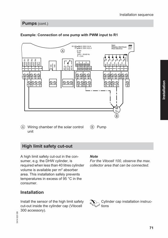
71
Example: Connection of one pump with PWM input to R1
A
M~1B
145
145PW
M R
1
PWM
R2
VBus
PWM
R3
PWM
R4
16 17 18 19 20 27 30 31 32 33 34 35
A Wiring chamber of the solar controlunit
B Pump
High limit safety cut-out
A high limit safety cut-out in the con-sumer, e.g. the DHW cylinder, isrequired when less than 40 litres cylindervolume is available per m2 absorberarea. This installation safely preventstemperatures in excess of 95 °C in theconsumer.
NoteFor the Vitocell 100, observe the max.collector area that can be connected.
Installation
Install the sensor of the high limit safetycut-out inside the cylinder cap (Vitocell300 accessory).
Cylinder cap installation instruc-tions
Installation sequence
Pumps (cont.)
5414
620
GB
Inst
alla
tion

72
Connection
■ 3-core cable with a cross-section of1.5 mm2.
■ Systems with two collector arrays withone solar circuit pump require 2 highlimit safety cut-outs.
■ The changeover contact of the highlimit safety cut-out allows a fault mes-sage to be issued. For this, observethe influence of the speed control onthe message signal. If necessary, setparameter "Control" to "On/Off" (seepage 140).
M1~
?
27 30 31 32 33 34 35
A
B
DC
E
A Wiring chamber of the solar controlunit
B Junction box (on site)C Solar circuit pump or primary pump
for additional consumers with highlimit safety cut-out
D High limit safety cut-outE Fault message facility
Installation sequence
High limit safety cut-out (cont.)
5414
620
GB

73
Temperature setting
Delivered condition: 120 °CRequires adjustment to 95 °C
High limit safety cut-out installa-tion instructions
Central fault message facility
■ In accordance with the diagram, a cen-tral fault message facility can be con-nected to the zero volt output R7. Thisrelay is then unavailable for any otherfunction.
■ For settings, see page 141.
B
C
D
N L?
R6
R5
R4
R3
R2
R1 L
Netz
Red eléctricaRéseau électrique T6,3A
230V
R7-
A
R7-
M
R7-
R
AC 250V 0,8 AAC 250V 4(2) A
R1-R6R7
T40IP20230V ~ 50-60 HzP = 3VA
N
N N N N N
27 30 31 32 33 34 35
A
A Wiring chamber of the solar controlunit
B ON/OFF switch (on site)
C Power supplyD Central fault message facility
Installation sequence
High limit safety cut-out (cont.)
5414
620
GB
Inst
alla
tion

74
Collector temperature sensor
Installation
Collector installation instructions
Connection
In accordance with system example andpage 68.
Connect sensor to S1 or, in conjunctionwith 2 collector arrays to S9.Extension of the connecting lead:2-core cable with a cross-section of1.5 mm2.
NoteNever route this lead together with230/400 V cables.
Cylinder temperature sensor
Installation
With the threaded elbow.
Vitocell 100-B and Vitocell 300-B
Installation instructions for theDHW cylinder
Vitocell 100-V and Vitocell 300-V
1.3.
2.
A Heating water return connection
Installation sequence
Sensors
5414
620
GB
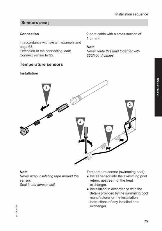
75
Connection
In accordance with system example andpage 68.Extension of the connecting lead:Connect sensor to S2.
2-core cable with a cross-section of1.5 mm2.
NoteNever route this lead together with230/400 V cables.
Temperature sensors
Installation
1.
4.
3.
2.
NoteNever wrap insulating tape around thesensor.Seal in the sensor well.
Temperature sensor (swimming pool):■ Install sensor into the swimming pool
return, upstream of the heatexchanger.
■ Installation in accordance with thedetails provided by the swimming poolmanufacturer or the installationinstructions of any installed heatexchanger
Installation sequence
Sensors (cont.)
5414
620
GB
Inst
alla
tion
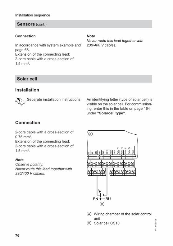
76
Connection
In accordance with system example andpage 68.Extension of the connecting lead:2-core cable with a cross-section of1.5 mm2.
NoteNever route this lead together with230/400 V cables.
Solar cell
Installation
Separate installation instructions An identifying letter (type of solar cell) isvisible on the solar cell. For commission-ing, enter this in the table on page 164under "Solarcell type".
Connection
2-core cable with a cross-section of0.75 mm2.Extension of the connecting lead:2-core cable with a cross-section of1.5 mm2.
NoteObserve polarity.Never route this lead together with230/400 V cables.
GND
S8 S9 S10
S11
S12
CS1
0
Imp1
Imp2
PWM
R1
PWM
R2
VBus
PWM
R3
PWM
R4
8 9 10 11 12 13 14 15 16 17 18 19 20
BUBNB
A
A Wiring chamber of the solar controlunit
B Solar cell CS10
Installation sequence
Sensors (cont.)
5414
620
GB

77
Settings
See page 164.
Power supply
Regulations
Make the power supply connection andimplement all earthing measures (i.e.RCD circuit) in accordance withIEC 60364-4-41, the requirements ofyour local power supply utility, VDE ornational regulations.
NL
?
R6
R5
R4
R3
R2
R1 L
Netz
Red eléctricaRéseau électrique T6,3A
230V
R7-
A
R7-
M
R7-
R
AC 250V 0,8 AAC 250V 4(2) A
R1-R6R7
T40IP20230V ~ 50-60 HzP = 3VA
N
N N N N N
27 30 31 32 33 34 35
AA
B
C
A Wiring chamber of the solar controlunit
B Mains isolator, two-pole (on site)C Mains voltage 230 V/50 Hz
Installation sequence
Solar cell (cont.)
5414
620
GB
Inst
alla
tion

78
■ Protect the cable to the control unitwith an appropriate fuse/MCB.
■ Disconnect the system by means of adevice that simultaneously separatesall non-earthed conductors withat least 3mm contact separation.
■ Connect the power supply in accord-ance with the diagram.
DangerIncorrect core termination cancause severe injuries and dam-age to the equipment.Never interchange cores "L" and"N".L brownN bluePE green/yellow
Installation sequence
Power supply (cont.)
5414
620
GB

79
1. Check whether all electrical connec-tions have been correctly made.
2. Check that the high limit safety cut-out and temperature limiter (ifrequired) are connected.
3. Switch ON the power; the solar con-trol unit then begins an initialisingphase.The standard display then appears(see following diagram).The solar control unit is now in auto-matic mode.
Navigation through the menu
Controls
B
30.04.2009
Tcol
Tcylb
10:59
47.7 °C
35.4 °C
A
A Standard displayThe standard display will automat-ically show after approx. 4 min, ifno adjustments are made.
B OK key■ Pressed once: Confirmation of
the menu selection■ Pressed twice: Confirmation of
a value change■ Calling up the main menu■ Back to the standard display
from any menu
■ Back to the previous menu point■ Terminating an adjustment
already begun (the valuereverts to its previous setting)
/ Cursor keysNavigation through the menuThe display can only show fourlines of the menu at a time. Thearrow on the l.h. side of the displayhighlights the available menuitem.
Commissioning
Switching the power ON54
14 6
20 G
B
Serv
ice

80
/ Cursor keysTo display values (with graphicsupport; see the following dia-gram)
ΔT1on
8.0K
1.5 =8.0 20.0
A
B C
A ParametersB Minimum valueC Maximum value
Entering the operator code
Press the following keys:
1. "Hauptmenü" will be dis-played.
Hauptmenü:MesswerteMeldungenSolar
2. for "Bedienercode" (lowestmenu point).
Hauptmenü:SD-KarteManuellbetriebBedienercode
3. OK to confirm.
Bedienercode:
0000
Commissioning
Navigation through the menu (cont.)
5414
620
GB

81
4. / for "0200".Confirm every figure with OK.Key sequence: OK/ / / OK/OK/ OK
NoteAfter commissioning set the operatorcode to "0000".
Language selection
Press the following keys:
1. "Hauptmenü" will be dis-played.
Hauptmenü:MesswerteMeldungenSolar
2. for "Experte" (lowest menupoint).
Hauptmenü:ManuellbetriebBedienercodeExperte
3. OK to confirm.
4. for "Sprache" (lowest menupoint).
Experte:
DisplaySprache
Uhr
5. OK to confirm.
6. / for the required language.
7. OK to confirm.
Commissioning
Entering the operator code (cont.)
5414
620
GB
Serv
ice

82
Make the following settings at thesolar control unit:
Main menu■ "System"■ "Setting values"
– "Time"First set the hour, then the minutes.
– "Date"Set the year, month and day in thatorder.
For further time adjustments, seepage 166.
Adjusting the display
The level of backlighting and font colourcan be selected (black on a white back-ground or vice-versa) (see page 166).
Setting parameters
Selecting the system and hydraulic type
Prior to setting the system parameters,the "System" and "Hyd. Type" (seechapter "Systems" from page 94) mustbe selected in accordance with the fol-lowing criteria:
System:■ How many collector arrays have been
installed?■ How many consumers have been
installed?
Hydraulic type:■ Which hydraulic version (pump or
valve control)?
NoteBy selecting the "System" and "Hyd.Type" relays and sensors are automati-cally assigned.
Make the following settings at thesolar control unit:
Main menu■ "Solar"■ "Options"
– "System"Delivered condition: 1Set a value.
– "Hyd. Type"Delivered condition: 1Set a value.
Commissioning
Setting the time and date
5414
620
GB

83
NoteAll parameters are reset into their deliv-ered condition when the setting for "Sys-tem" is changed.
Setting pump parameters
Check which type of pumps are connec-ted and set parameter "Control"accordingly (see page 69).
Activating additional functions
■ For each system, additional functionscan be activated (see the table for therespective system from page 95).Functions for which the same relayoutput is used can only be used alter-nately.Example system 1 (see page 95):The "Parallel relay" function can onlybe activated if no additional functionfor DHW heating was activated.
■ For functions that can be selectedindependently of the relay assign-ment, see the following table.
Function PageCylinder priority control(only in conjunction with several consumers, systems 3 to 5)
117
Collector emergency stop 118Interval function 127Collector cooling function 128Return cooling function 129Frost protection 129Target temperature 130Cylinder (2 to 4) 134Overheat 134Collector minimum limit 135Cyclical heating 135
Commissioning
Setting parameters (cont.)
5414
620
GB
Serv
ice

84
Resetting parameters into their delivered state
Make the following settings at thesolar control unit:
Main menu■ "Solar"■ "Options"
– "System"Set value "1".
Carrying out a relay test (testing actuators)
The relays can be switched individuallyor together.
Make the following settings at thesolar control unit:
Main menu■ "Manual mode"
– "All relays"or
– "Relay 1"to"Relay 7"
Switching states:■ "ON"■ "Auto" ≙ Controlled operation■ "OFF"
After the relay test has been completed,select "Auto" for all relays.
NoteIf a relay is in manual mode, the standarddisplay will indicate accordingly:
30.04,2009TcolTcylb
10:5947.7 °C35.4 °C
Manual mode
Commissioning
Setting parameters (cont.)
5414
620
GB

85
Subject to system configuration, the fol-lowing values can be scanned with keys / :
Main menu■ "Actual values"
"Actual values:" ExplanationTcol °C Collector temperatureTcol2 °C Collector temperature, collector array 2Tcylb °C Cylinder temperature, bottomTcyl2b °C Cylinder temperature, consumer 2, bottomTcyl3b °C Cylinder temperature, consumer 3, bottomTcyl4b °C Cylinder temperature, consumer 4, bottomTby °C Bypass temperatureT-HE °C Temperature external heat exchangerCyl. add. – Additional function for DHW heating is activeTime – Date –
Relay Relay 1toRelay 4
% Speed, relay 1 to 4
Relay 5toRelay 7
– Switching state, relays 5 to 7
Sensors Sen.1toSen.12
°C Temperature sensors 1 to 12Display when there is a sensor break: 888.8Display when there is a sensor short circuit: −888.8
NoteThe temperature can also be displayed in °F (degreeFahrenheit) (selection, see 165)
Intens. W/qm Insolation intensity (actual insolation) in conjunctionwith the solar cell
Scanning the statement
Subject to system configuration, the fol-lowing values can be scanned with keys / :
Main menu■ "Solar"■ "Statement"
Service scans
Scanning temperatures and operating conditions54
14 6
20 G
B
Serv
ice

86
"Solar statement:" ExplanationColmax °C Maximum collector temperature, collector array 1Col2max °C Maximum collector temperature, collector array 2Cylmax °C Maximum DHW cylinder temperatureCyl2max °C Maximum cylinder temperature, consumer 2Cyl3max °C Maximum cylinder temperature, consumer 3Cyl4max °C Maximum cylinder temperature, consumer 4Relay 1toRelay 7
h Hours run for relays R1 to R7
Days – Days run, solar control unit
To reset the values, except for daysrun:
Whilst this value is displayed, press thefollowing keys:
1. OK "Delete?""Yes" is displayed.
2. OK to confirm.
Scanning the heat yield and temperatures
For a description of the heat statement,see from page 141.
Main menu■ "HM"■ "HM 1"
or"HM 2"
■ "Tflow" (heat meter flow temperature)■ "Tretn" (heat meter return tempera-
ture)■ "Heat"
NoteAdd the values for Wh, kWh and MWhtogether.
Resetting the amount of heat
Whilst this value is displayed, press thefollowing keys:
1. OK "Delete?""Yes" is displayed.
2. OK to confirm.
Service scans
Scanning the statement (cont.)
5414
620
GB

87
Main menu■ "Messages"
"Messages:" ExplanationLoading cyl...(only with several consumers)
Consumer displayed is being heated.
Pause cyl...(only with several consumers)
Only in conjunction with cyclical heating (seepage 135):Pause in the heating of the displayed con-sumer.
Cyl set... Consumer displayed has reached its setvalue.
Fault A fault has occurred at the solar control unit (for"Scanning the fault display", see page 88).
SW version Software versionHW version Hardware version
Priority of the displayed messages in the standard display
■ Manual mode■ Fault■ Loading cyl...■ Pause cyl...
Service scans
Scanning messages54
14 6
20 G
B
Serv
ice

88
If the system develops faults, the displaybacklighting flashes and "Fault" will bedisplayed.
30.04.2009TcolTcylb
10:5947.7 °C35.4 °C
Fault
Checking and acknowledging faults
Press the following keys:
1. "Main menu" will be dis-played.
2. for "Messages".
3. OK to confirm.
4. for scanning the fault.
5. OK to acknowledge.
6. for scanning further faults (seethe following table).
NoteIf an acknowledged fault is not removed,the fault message will be re-displayed.
Troubleshooting
Fault messages
5414
620
GB

89
Displayed faults
"Messages:""Fault" Cause Remedy!Interruption>Sensor <
The sensor has suffered abreak
Check the sensor con-cerned (see page 92).
!Sensor circuit>Sensor <
The sensor has suffered ashort circuit
Check the sensor con-cerned (see page 92).
?Night circ.
NoteA central fault messagefacility that may be connec-ted to relay R7 will not beswitched ON.
Recirculation via gravity Check any installed non-return damper (Solar-Divi-con) or install one.
?ΔT too highSee information above.
Circulation pump faulty.Message only if solarheating takes place forlonger than 20 min at atemperature differentialbetween collector andconsumer greater than50 K.
Check pump connectionand pump.
!EEPROM Internal fault. Switch solar control unitOFF and ON again after abrief interval. Check all set-tings. If the fault recurs,replace the solar controlunit.
!Processors
!SD module fault Display cause of the fault:Press OK (seepage 147).
See page 147.SD fault
Troubleshooting
Fault messages (cont.)
5414
620
GB
Serv
ice

90
Faults without display
■ Solar circuit pump runs hot, but no heat transport from the collector arrayto the consumer
■ Flow and return lines are equally hot■ Noisy pipeworkAir in the system? ⇒No YesA dirt trap may beblocked.Clean dirt trap.
Vent the system (see collector service instructions).
The solar circuit pump starts briefly, then stops and starts again, etc:Temperature differential ΔT too small? ⇒No YesCollector temperature sensor locatedincorrectly?
Change "ΔTon" and "ΔToff"(see page 151).
No YesCheck interval func-tion (seepage 127).
Locate the collec-tor temperaturesensor at the hot-test place on thesolar flow.
The solar circuit pump starts too late:Start temperature differential "ΔTon" too great? ⇒No YesCollector temperature sen-sor located incorrectly?If yes, poss. activate inter-val function (seepage 127).
Change "ΔTon" and "ΔToff" (see page 151).
Troubleshooting
Fault messages (cont.)
5414
620
GB

91
Very large temperature differential between the collector array and consumersduring operation (heat cannot be dissipated):Solar circuit pump faulty? ⇒No YesSolar heat exchanger scaled up? ⇒ Check the solar circuit pump:
■ Check the operating voltage(ON/OFF switch, powercable).
■ Check fuse F1, 6.3 A (slow).If fuse F1 is faulty; replace it(see page 93).
No YesSolar heat exchanger blocked?⇒
Descale solarheatexchanger.No Yes
Solar heatexchangersized too small.
Flush the solarthermal sys-tem (see col-lector serviceinstructions).
The solar circuit pump does not run, although the temperature in the collectorarray is higher than that in the consumer.Display dark?⇒Yes No■ Check the operating voltage (ON/OFF
switch, power cable).■ Check fuse F1, 6.3 A (slow).If fuse F1 is faulty; replace it (seepage 93).
Check whether the solar circuit pumpruns in manual mode (see page 84).No YesIs pump current enabledby the solar control unit?⇒
Start tem-perature dif-ferential"ΔTon" toogreat?If yes,changevalue (seepage 151).
No YesCheck fuseF1, 6.3 A(slow).If fuse F1 isfaulty;replace it(seepage 93).Otherwisereplacesolar con-trol unit.
Solar circuitpumpseized.Free thepump shaft.Replace thepump if itrefuses torun.
Troubleshooting
Fault messages (cont.)
5414
620
GB
Serv
ice

92
0.1
1
10
100
1000
-20 0 20 40 60 80 100 120 140Temperature in °C
Res
ista
nce
in k
Ω
AB
25
A Resistance 20 kΩ(sensor S1, S9, collector tempera-ture sensor)
B Resistance 10 kΩ(sensors S2 to S8, S10 to S12)
1. Disconnect the respective sensorand measure its resistance.
2. Compare the measurement with theactual temperature (for scanning seepage 85). Check the installation and,in case of severe deviation, replacethe sensor.
Specification
Sensor NTC 10 kΩ at 25 °C 20 kΩ at 25 °CProtection IP 53 IP 53Permissible ambienttemperature
■ during operation −20 to + 90 °C −20 to + 200 °C■ during storage and
transport−20 to + 70 °C −20 to + 70 °C
Checking relays (actuators)
See chapter "Relay test" on page 84.
Troubleshooting
Checking sensors
5414
620
GB

93
BR
6
R5
R4
R3
R2
R1 L
Netz
Red eléctricaRéseau électrique T6,3A
230V
R7-
A
R7-
M
R7-
RAC 250V 0,8 AAC 250V 4(2) A
R1-R6R7
T40IP20230V ~ 50-60 HzP = 3VA
N
N N N N N NN
27 30 31 32 33 34 35
A
A Solar control unit wiring chamberB Fuse, 6.3 A (slow)
Open the solar control unit wiring cham-ber.A spare fuse is included in the fuseholder.
Troubleshooting
Changing the fuse54
14 6
20 G
B
Serv
ice

94
■ With the Vitosolic 200 solar control unit7 systems with different hydraulictypes can be implemented.
■ System selection in accordance withthe number of collector arrays andconsumers.
■ Selection of the hydraulic type inaccordance with the hydraulic connec-tion (e.g. via pumps or valves).
■ For each system, additional functionscan be activated (see the table for therespective system from page 95).Functions for which the same relayoutput is used can only be used alter-nately.For explanations and settings seefrom page 112.
Overview
System Number of collectorarrays
Number of consumers
Delivered condition:1 (see page 95)2 (see page 96)
3 (see page 98)
4 (see page 101)
5 (see page 105)
6 (see page 107)
7 (see page 110)
Function description
Systems
5414
620
GB

95
System 1
S1
R1
S2
Relay and sensor assignment
Functions Relay R... Sensor S...1 2 3 4 5 6 7 1 2 3 4 5 6 7 8 9
Assignment byscheme
x x x
Function block 1 x x x Cooling function x Ext. Heat exchanger x x Additional function x Parallel relay x Function block 2 x x x DHW heating x x x Bypass x x Function block 3 x x x Central fault message x Booster suppression*3 x
*3 Only if this function is achieved via contact control (see page 132).
Function description
Systems (cont.)
5414
620
GB
Serv
ice

96
System 2
Hydraulic type 1
S1 S9
R1 R2
S2
Relay and sensor assignmentFunctions Relay R... Sensor S...
1 2 3 4 5 6 7 1 2 3 4 5 6 7 8 9Assignment byscheme
x x x x x
Function block 1 x x x Cooling function x Ext. Heat exchanger x x Additional function x Parallel relay x Function block 2 x x x DHW heating x x x Bypass x x Function block 3 x x x Central fault message x Booster suppression*3 x
*3 Only if this function is achieved via contact control (see page 132).
Function description
Systems (cont.)
5414
620
GB
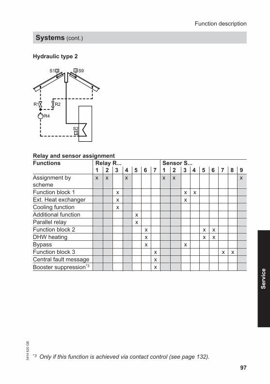
97
Hydraulic type 2
S1 S9
R1 R2
S2
R4
Relay and sensor assignmentFunctions Relay R... Sensor S...
1 2 3 4 5 6 7 1 2 3 4 5 6 7 8 9Assignment byscheme
x x x x x x
Function block 1 x x x Ext. Heat exchanger x x Cooling function x Additional function x Parallel relay x Function block 2 x x x DHW heating x x x Bypass x x Function block 3 x x x Central fault message x Booster suppression*3 x
*3 Only if this function is achieved via contact control (see page 132).
Function description
Systems (cont.)
5414
620
GB
Serv
ice

98
System 3
Hydraulic type 1
S1
R1R4
S2 S4
Relay and sensor assignmentFunctions Relay R... Sensor S...
1 2 3 4 5 6 7 1 2 3 4 5 6 7 8 9Assignment byscheme
x x x x x
Function block 1 x x x Ext. Heat exchanger x x Additional function x Parallel relay x Function block 2 x x x DHW heating x x x Bypass x x Function block 3 x x x Central fault message x Booster suppression*3 x
*3 Only if this function is achieved via contact control (see page 132).
Function description
Systems (cont.)
5414
620
GB
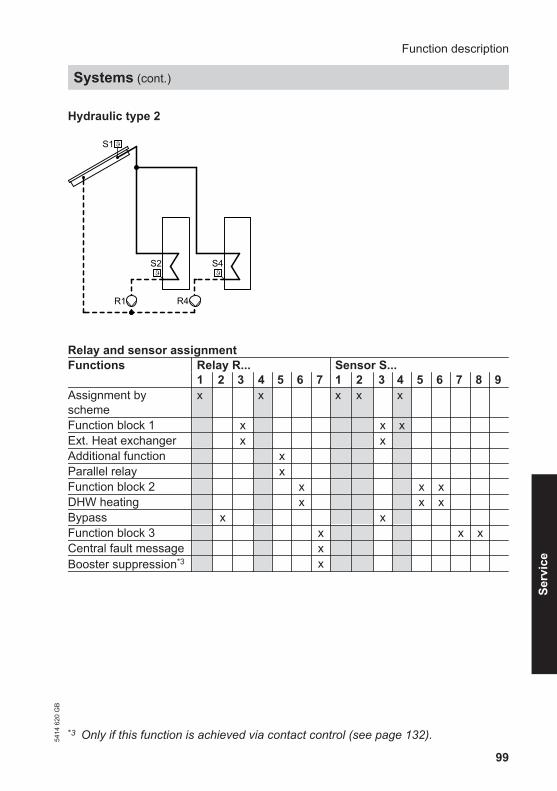
99
Hydraulic type 2
S1
R1 R4
S2 S4
Relay and sensor assignmentFunctions Relay R... Sensor S...
1 2 3 4 5 6 7 1 2 3 4 5 6 7 8 9Assignment byscheme
x x x x x
Function block 1 x x x Ext. Heat exchanger x x Additional function x Parallel relay x Function block 2 x x x DHW heating x x x Bypass x x Function block 3 x x x Central fault message x Booster suppression*3 x
*3 Only if this function is achieved via contact control (see page 132).
Function description
Systems (cont.)
5414
620
GB
Serv
ice

100
Hydraulic type 3
S1
R2 R4
S2 S4
R1
Relay and sensor assignmentFunctions Relay R... Sensor S...
1 2 3 4 5 6 7 1 2 3 4 5 6 7 8 9Assignment byscheme
x x x x x x
Function block 1 x x x Ext. Heat exchanger x x Additional function x Parallel relay x Function block 2 x x x DHW heating x x x Bypass x x Function block 3 x x x Central fault message x Booster suppression*3 x
*3 Only if this function is achieved via contact control (see page 132).
Function description
Systems (cont.)
5414
620
GB

101
System 4
Hydraulic type 1
S1 S9
R1 R2
S2 S4
R4
Relay and sensor assignmentFunctions Relay R... Sensor S...
1 2 3 4 5 6 7 1 2 3 4 5 6 7 8 9Assignment byscheme
x x x x x x x
Function block 1 x x x Ext. Heat exchanger x x Additional function x Parallel relay x Function block 2 x x x DHW heating x x x Bypass x x Function block 3 x x x Central fault message x Booster suppression*3 x
*3 Only if this function is achieved via contact control (see page 132).
Function description
Systems (cont.)
5414
620
GB
Serv
ice
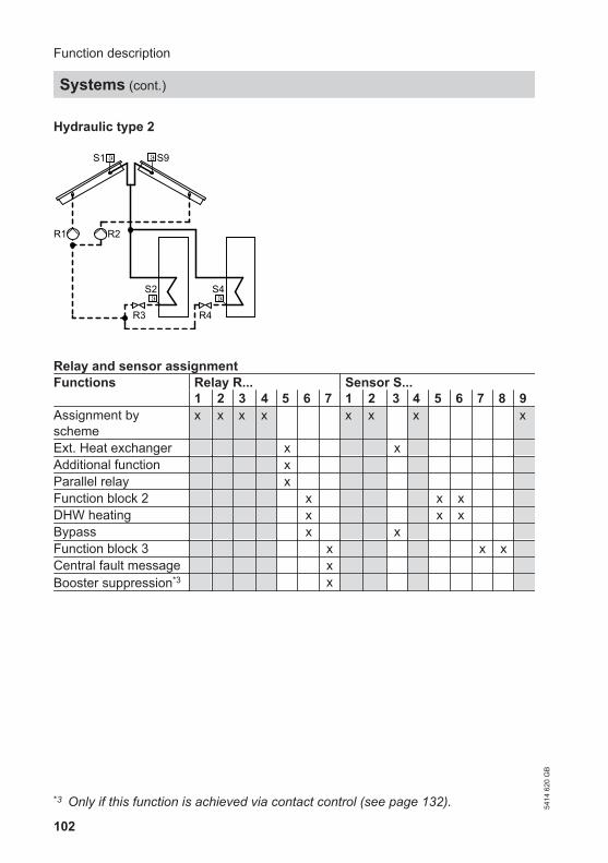
102
Hydraulic type 2
S1 S9
R1 R2
S2 S4
R3 R4
Relay and sensor assignmentFunctions Relay R... Sensor S...
1 2 3 4 5 6 7 1 2 3 4 5 6 7 8 9Assignment byscheme
x x x x x x x x
Ext. Heat exchanger x x Additional function x Parallel relay x Function block 2 x x x DHW heating x x x Bypass x x Function block 3 x x x Central fault message x Booster suppression*3 x
*3 Only if this function is achieved via contact control (see page 132).
Function description
Systems (cont.)
5414
620
GB

103
Hydraulic type 3
S1 S9
R1 R2
S2 S4
R4R3
Relay and sensor assignmentFunctions Relay R... Sensor S...
1 2 3 4 5 6 7 1 2 3 4 5 6 7 8 9Assignment byscheme
x x x x x x x x
Ext. Heat exchanger x x Additional function x Parallel relay x Function block 2 x x x DHW heating x x x Bypass x x Function block 3 x x x Central fault message x Booster suppression*3 x
*3 Only if this function is achieved via contact control (see page 132).
Function description
Systems (cont.)
5414
620
GB
Serv
ice

104
Hydraulic type 4
S1 S9
R1 R2
S2 S4
R4
R3
Relay and sensor assignmentFunctions Relay R... Sensor S...
1 2 3 4 5 6 7 1 2 3 4 5 6 7 8 9Assignment byscheme
x x x x x x x x
Ext. Heat exchanger x x Additional function x Parallel relay x Function block 2 x x x DHW heating x x x Bypass x x Function block 3 x x x Central fault message x Booster suppression*3 x
*3 Only if this function is achieved via contact control (see page 132).
Function description
Systems (cont.)
5414
620
GB

105
System 5
Hydraulic type 1
S1
S2 S4 S5
R2 R4 R5
R1
Relay and sensor assignmentFunctions Relay R... Sensor S...
1 2 3 4 5 6 7 1 2 3 4 5 6 7 8 9Assignment byscheme
x x x x x x x x
Function block 1 x x x Ext. Heat exchanger x x Additional function x Function block 2 x x x DHW heating x x x Bypass x x Function block 3 x x x Central fault message x Booster suppression*3 x
*3 Only if this function is achieved via contact control (see page 132).
Function description
Systems (cont.)
5414
620
GB
Serv
ice

106
Hydraulic type 2
S1
S2 S4 S5
R1 R2 R4
Relay and sensor assignmentFunctions Relay R... Sensor S...
1 2 3 4 5 6 7 1 2 3 4 5 6 7 8 9Assignment byscheme
x x x x x x x
Function block 1 x x x Ext. Heat exchanger x x Additional function x Parallel relay x Function block 2 x x x DHW heating x x x Bypass x x Function block 3 x x x Central fault message x Booster suppression*3 x
*3 Only if this function is achieved via contact control (see page 132).
Function description
Systems (cont.)
5414
620
GB

107
System 6
Hydraulic type 1
R1 R2
S1 S9
S2 S4 S5
R4 R5 R6
Relay and sensor assignmentFunctions Relay R... Sensor S...
1 2 3 4 5 6 7 1 2 3 4 5 6 7 8 9Assignment byscheme
x x x x x x x x x x
Function block 1 x x x Ext. Heat exchanger x x Additional function x Function block 3 x x x Central fault message x Booster suppression*3 x
*3 Only if this function is achieved via contact control (see page 132).
Function description
Systems (cont.)
5414
620
GB
Serv
ice

108
Hydraulic type 2
R5 R6
S1 S9
S2 S4 S5
R1 R2 R4
Relay and sensor assignmentFunctions Relay R... Sensor S...
1 2 3 4 5 6 7 1 2 3 4 5 6 7 8 9Assignment byscheme
x x x x x x x x x x
Function block 1 x x x Ext. Heat exchanger x x Additional function x Bypass x x Function block 3 x x x Central fault message x Booster suppression*3 x
*3 Only if this function is achieved via contact control (see page 132).
Function description
Systems (cont.)
5414
620
GB

109
Hydraulic type 3
R1 R2
S1 S9
S2 S4 S5
R4 R5 R6
R3
Relay and sensor assignmentFunctions Relay R... Sensor S...
1 2 3 4 5 6 7 1 2 3 4 5 6 7 8 9Assignment byscheme
x x x x x x x x x x x
Ext. Heat exchanger x x Bypass x x Function block 3 x x x Central fault message x Booster suppression*3 x
*3 Only if this function is achieved via contact control (see page 132).
Function description
Systems (cont.)
5414
620
GB
Serv
ice

110
System 7
Hydraulic type 1
R2 R4 R5 R6
S1
S2 S4 S5 S6
R1
Relay and sensor assignmentFunctions Relay R... Sensor S...
1 2 3 4 5 6 7 1 2 3 4 5 6 7 8 9Assignment byscheme
x x x x x x x x x x
Function block 1 x x x Ext. Heat exchanger x x Additional function x Bypass x x Function block 3 x x x Central fault message x Booster suppression*3 x
*3 Only if this function is achieved via contact control (see page 132).
Function description
Systems (cont.)
5414
620
GB

111
Hydraulic type 2
R1 R2 R4 R5
S1
S2 S4 S5 S6
Relay and sensor assignmentFunctions Relay R... Sensor S...
1 2 3 4 5 6 7 1 2 3 4 5 6 7 8 9Assignment byscheme
x x x x x x x x x
Function block 1 x x x Ext. Heat exchanger x x Additional function x Function block 2 x Parallel relay x Bypass x x Function block 3 x x x Central fault message x Booster suppression*3 x
*3 Only if this function is achieved via contact control (see page 132).
Function description
Systems (cont.)
5414
620
GB
Serv
ice

112
■ If the relays 3, 6 and 7 have not beenassigned by the scheme ("System"),they could, for example, be used forthe Function blocks 1 to 3 (see thetable for the respective system frompage 95).
■ Within a function block, there are 4functions that can be combined asrequired:– 2 thermostat functions– 1 temperature differential control– 1 time switch with three periods that
can be activated
■ In the delivered condition, certain sen-sors are assigned to these functions(Reference sensors). These sensorscan be switched, i.e. sensors alreadyused can be used for additional func-tions (see page 161).
■ Make all settings in menu "System"(see from page 158).
A relay assigned to a function block willonly switch if the conditions of all acti-vated functions are met. These func-tions act like individual switches in aserial circuit (see the following dia-gram).
Function description
Function blocks
5414
620
GB

113
Function block 1
R3
Thermost.1(Sensor S3)Th1onTh1off
Thermost.2(Sensor S4)Th2onTh2off
(S3-S4)∆T-Fct5
∆T5on∆T5off
t-onTime switch 1
t-off
R6
Thermost.3(Sensor S5)Th3onTh3off
Thermost.4(Sensor S6)Th4onTh4off
(S5-S6)∆T-Fct6
∆T6on∆T6off
t-onTime switch 2
t-off
Function block 2
R7
Thermost.5(Sensor S7)Th5onTh5off
Thermost.6(Sensor S8)Th6onTh6off
(S7-S8)∆T-Fct7
∆T7on∆T7off
t-onTime switch 3
t-off
Function block 3
Thermostat function
The respective relay switches subject tothe temperature at the reference sensor(see the following table).
Function description
Function blocks (cont.)
5414
620
GB
Serv
ice

114
Different effects can be achieved by determining the start and stop tempera-tures:"Thon" < "Thoff"Adjusting the values see frompage 158.
"Thon" > "Thoff"Adjusting the values, see frompage 158.
e.g. for reheating e.g. for utilising excess heat
ThoffThon
R offR on
ThonThoff
R offR on
See also example 1 on page 114 andexample 2 on page 115.
Differential temperature control (ΔT control)
The corresponding relay switches ON ifthe start temperature differential isexceeded and OFF if the stop tempera-ture is not achieved.
Adjusting the values, see frompage 158.Also see example 2 on page 115.
Time switch
The corresponding relay switches ON atthe start time "t on" and OFF at the stoptime "t off" (3 periods can be activa-ted).
Adjusting the values, see frompage 159.See also the following example.
Example 1 — Switching a DHW circulation pump
Used functions:■ Thermostat function 1■ Time switch 1
Function description
Function blocks (cont.)
5414
620
GB

115
Thermost.1 R3Time switch 1
S3
R3
Th1on < 50 °CTh1off > 55 °C
To switch a DHW circulation pump, acti-vating the time switch is sufficient. TheDHW circulation pump can also be star-ted subject to temperature with the sen-sor S3 in the DHW circulation line.For parameters in the delivered condi-tion, see from page 158.
Make the following settings at thesolar control unit:
1. Main menu■ "System"■ "Options"
– "Thermost. 1"Set "Yes".
– "Time switch 1"Set "Yes".
2. Main menu■ "System"■ "Setting values"
– "Th1on"Set "50".
– "Th1off"Set "55".
– "Time switch 1"Select period "t on" and "t off".
Example 2— Switching the boiler circuit pump of a solid fuelboiler
Used functions:■ Thermostat function 1■ "ΔT-Fct5"
Function description
Function blocks (cont.)
5414
620
GB
Serv
ice

116
R3ΔT-Fct5
S3-S5 > ΔT5onTh1on > 65 °CTh1off < 60 °C
Thermost. 1
S5S3
R3
■ Boiler circuit pump R3 on:Temperature differential "ΔT5on" isexceeded and "Th1on" is reached
■ Boiler circuit pump R3 off:Temperature differential "ΔT5off" or"Th1off" is not reached
For parameters in the delivered condi-tion, see from page 158.
Make the following settings at thesolar control unit:
1. Main menu■ "System"■ "Options"
– "Thermost.1"Set "Yes".
– "ΔT-Fct5"Set "Yes".
2. Main menu■ "System"■ "Setting values"
– "Th1on"Set "65".
– "Th1off"Set "60".
– "ΔT5on"Set a value.
– "ΔT5off"Set a value.
3. Switch sensor S4:
Main menu■ "System"■ "Contractor"
– "Sen2 ΔT5Fct"Set "5".
Cylinder temperature control
The solar circuit pump starts; the cylinderis heated:■ When the selected start temperature
differential "ΔTon" is exceeded.
Function description
Function blocks (cont.)
5414
620
GB

117
The solar circuit pump stops; cylinderheating terminates in accordance withthe following criteria:■ When the selected stop temperature
differential "ΔToff" is not reached.■ The corresponding consumer is
blocked (sensor faulty or high limittemperature of 90 °C is reached).
■ The collector array concerned isblocked (collector temperature sensorfaulty or the temperature for an emer-gency shutdown of the collector "Tco-lemoff" (see page 154) has beenreached.
■ Set cylinder temperature "Tcyl set"(see page 151) has been reached.
Make the following settings at thesolar control unit:
Main menu■ "Solar"■ "Setting values"
– "ΔTon"/"ΔToff"Set a value.
Cylinder temperature limit
When the set temperature "Tcyl set"has been exceeded (see page 151) thecorresponding circulation pump stops toprevent the consumer overheating. If theconsumer cools down by more than "ΔT-Cylset", it will be heated again by thesolar thermal system.A safety shutdown occurs when thesafety temperature of 90 °C has beenreached.
Make the following settings at thesolar control unit:
Main menu■ "Solar"■ "Contractor"
– "ΔT-Cylset"Set a value.
Cylinder priority control
The consumers are heated up in numer-ical sequence, until the respective settemperature "Tcyl set" has beenreached.
NoteConsumers with the same priority valueare heated up simultaneously. We can-not recommend this setting.
Function description
Cylinder temperature control (cont.)
5414
620
GB
Serv
ice

118
Make the following settings at thesolar control unit:
Main menu■ "Solar"■ "Setting values"
– "Priority Cyl1" etc.Set a value.
Collector emergency stop
The solar thermal system enters stagna-tion when temperature "Tcolemoff" isreached. Heating of consumers is thenno longer possible.
Make the following settings at thesolar control unit:
Main menu■ "Solar"■ "Setting values"
– "Tcolemoff"Set a value.
Bypass
Bypass versions■ With collector temperature and bypass
sensorImplementation via relays R2, R6 orR7 (subject to the selected system andhydraulic type, see from page 94).
■ With solar cellRequires no relay assignment.
■ With solar cell and collector tempera-ture sensorImplementation via relays R2, R6 orR7 (subject to the selected system andhydraulic type, see from page 94).
Function description
Cylinder priority control (cont.)
5414
620
GB

119
Version 1 – bypass circuit with collector temperature sensor andbypass sensor
S1
R1RS9
R1 Solar circuit pumpR Bypass pump (at R2, R6 or R7)S1 Collector temperature sensorS9 Bypass sensor
NTC sensors, 20 kΩ
■ Bypass pump on:When the start temperature differential"ΔTon" is exceeded between the col-lector temperature and the cylindertemperature.
■ Solar circuit pump on, bypass pumpoff:When the temperature differentialbetween the temperature at thebypass sensor and the cylinder tem-perature exceeds 2.5 K (permanentlyset).
■ Solar circuit pump off, bypass pumpon:When the temperature differentialbetween the temperature at thebypass sensor and the cylinder tem-perature falls by 1.5 K (permanentlyset).
Make the following settings at thesolar control unit:
1. Main menu■ "Solar"■ "Options"
– "Bypass"Set "Yes".
2. Main menu■ "Solar"■ "Contractor"
– "Sen. bypass"Set value "9".
– "Bypass"Set "Pump".
Function description
Bypass (cont.)
5414
620
GB
Serv
ice

120
Version 2 – bypass circuit with solar cell
R1
CS
S1
CS Solar cellR1 Solar circuit pumpS1 Collector temperature sensor
■ The solar circuit pump also assumesthe function of the bypass pump.
■ The solar control unit records the solarintensity via the solar cell.
■ Solar circuit pump on:When the selected insolation thresh-old "SC Byp." is exceeded.
■ Solar circuit pump off:The insolation falls for approx. 2 minbelow the set threshold.
Make the following settings at thesolar control unit:
1. Main menu■ "Solar"■ "Options"
– "SC bypass"Set "Yes".
2. Main menu■ "Solar"■ "Contractor"
– "Solarcell type"Set value from page 76.
3. Main menu■ "Solar"■ "Setting values"
– "SC Byp."Delivered condition 200 W/m2
Set value (see page 153).
Function description
Bypass (cont.)
5414
620
GB

121
Version 3 – bypass circuit with solar cell and collector tempera-ture sensor
R1RS1
CS
CS Solar cellR1 Solar circuit pumpR Bypass pump (at R2, R6 or R7)S1 Collector temperature sensor
■ The solar control unit records the solarintensity via the solar cell.
■ Bypass pump on:When the selected insolation thresh-old "SC Byp." is exceeded.
■ Bypass pump off, solar circuit pumpon:When the start temperature differential"ΔTon" is exceeded between the col-lector temperature and the cylindertemperature.
■ Bypass pump also off:The insolation falls for approx. 2 minbelow the set threshold.
■ Reference sensor for this bypass cir-cuit is the collector temperature sensorS1.
Make the following settings at thesolar control unit:
1. Main menu■ "Solar"■ "Options"
– "Bypass"Set "Yes".
– "SC bypass"Set "Yes".
2. Main menu■ "Contractor"■ "Sensors"
– "Solarcell type"Set value from page 76.
3. Main menu■ "Solar"■ "Setting values"
– "SC Byp."Delivered condition 200 W/m2
Set value (see page 153).
4. Main menu■ "Solar"■ "Contractor"
– "Sen. bypass"Delivered condition 3Set value "1".
– "Bypass"Set "Pump".
Function description
Bypass (cont.)
5414
620
GB
Serv
ice

122
In systems with several consumers,either an individual or all consumers canbe heated via the external heatexchanger. The consumers can beassigned via parameter "HE-cylinder".
NoteThe consumers will be heated up to theselected set temperature (delivered con-dition 60 °C).
We differentiate between two versions:1. Systems with several consumers and
a separate primary pump for eachconsumer.Sensor S9 inside the external heatexchanger NTC sensor, 20 kΩ.
2. Systems with one consumer or sev-eral consumers with consumer selec-tion via valve.Sensor S9 inside the external heatexchanger NTC sensor, 20 kΩ
Version 1
System Hyd. Type3 24 35 26 27 2
■ External heat exchanger pump (pri-mary circuit) on:Temperature differential between thecollector temperature sensor and thecylinder temperature sensor > starttemperature differential "ΔTon"
■ Consumer pump (secondary circuit)on:Temperature differential between thesensor in the external heat exchangerand the cylinder temperature sensor >start temperature differential "HEΔTon"
Function description
External heat exchanger
5414
620
GB

123
Example
1
2
2 consumers, hydraulic connection viapumps:System: 3Hydraulic type: 2Consumer 1 is heated via the externalheat exchanger.
According to the table on page 99 R3 isthe heat exchanger relay.
Function description
External heat exchanger (cont.)
5414
620
GB
Serv
ice

124
Primary pump (collector/ext. heatexchanger) to R3 on:■ S1−S2 > "ΔTon"
Delivered condition 8 K (seepage 152)
Secondary pump (heat exchanger/con-sumer 1) to R1 on:■ S9−S2 > "HE ΔTon"
Delivered condition 5 K (seepage 153)
Secondary pump (ext. heat exchanger/consumer 1) to R1 off:■ S9−S2 > "HE ΔToff"
Delivered condition 3 K (seepage 153)
Make the following settings at thesolar control unit:
1. Main menu■ "Solar"■ "Options"
– "System"Set value "3".
– "Hyd. Type"Set value "2".
– "Ext. HE"Set "Yes".
2. Main menu■ "Solar"■ "Contractor"
– "HE-cylinder"Set value "1".
– "Sen.HE.flow"Set value "9".
3. Main menu■ "Solar"■ "Setting values"
– "HE ΔTon"/"HE ΔToff"Set a value.
Version 2
System Hyd. Type1 12 1, 23 1, 34 1, 2, 45 16 1, 37 1
■ Pump corresponding collector array(primary circuit) on and valve for con-sumer to be heated open:Temperature differential between thecollector temperature sensor and thecylinder temperature sensor > starttemperature differential "ΔTon"
■ Pump external heat exchanger (sec-ondary circuit) on:
Function description
External heat exchanger (cont.)
5414
620
GB

125
Temperature differential between thesensor in the external heat exchangerand the cylinder temperature sensor >start temperature differential "HEΔTon"
Example
1
2
Function description
External heat exchanger (cont.)
5414
620
GB
Serv
ice

126
2 consumers, hydraulic connection viavalves:System: 3Hydraulic type: 3Consumer 1 is heated via the externalheat exchanger.According to the table on page 100 R3 isthe heat exchanger relay.
Primary pump (collector/ext. heatexchanger) to R1 on and valve to R2open:■ S1−S2 > "ΔTon"
Delivered condition 8 K (seepage 152)
Secondary pump (heat exchanger/con-sumer 1) to R3 on:■ S9−S2 > "HE ΔTon"
Delivered condition 5 K (seepage 153)
Secondary pump (ext. heat exchanger/consumer 1) to R3 off:■ S9−S2 > "HE ΔToff"
Delivered condition 3 K (seepage 153)
Make the following settings at thesolar control unit:
1. Main menu■ "Solar"■ "Options"
– "System"Set value "3".
– "Hyd. Type"Set value "3".
– "Ext. HE"Set "Yes".
2. Main menu■ "Solar"■ "Contractor"
– "HE-cylinder"Set value "1".
– "Sen.HE.flow"Set value "9".
3. Main menu■ "Solar"■ "Setting values"
– "HE ΔTon"/"HE ΔToff"Set a value.
Cooling function
■ This function can only be activated forsystem 1 and 2.
■ Solar circuit pump and relay R3 on:When the set temperature "Tcyl set"has been reached and the start tem-perature differential "ΔTon" is excee-ded.
■ Solar circuit pump and relay R3 off:When the selected stop temperaturedifferential "ΔToff" is not reached.
Make the following settings at thesolar control unit:
Main menu■ "Solar"■ "Options"
– "Cooling fct."Set "Yes".
Function description
External heat exchanger (cont.)
5414
620
GB

127
■ Activation of this function in systemswith unfavourably located collectortemperature sensor. Consequentlydelays in capturing the collector tem-perature are prevented.
■ The solar circuit pump can be switchedON for a set period in a freely selecta-ble interval.Delivered condition:The solar circuit pump is switched ONfrom 07:00 ("Int ON") to 19.00 ("IntOFF") h every 30 min ("Interval") for30 s ("Int time").This function is disabled from 19:00 to07:00 h.
NoteThis function will be suppressed if thecollector temperature sensor is faulty orthe collector shutdown temperature"Tcolemoff" has been reached (seepage 154).
Make the following settings at thesolar control unit:
1. Main menu■ "Solar"■ "Options"
– "Col.interv."Set "Yes".
2. Main menu■ "Solar"■ "Contractor"
– "Int time"Set the runtime for the solar cir-cuit pump in the selected inter-val.
– "Int ON"Set the time when the functionshould start.
– "Int OFF"Set the time when the functionshould stop.
3. Main menu■ "Solar"■ "Setting values"
– "Interval"Interval between starting andstopping the solar circuit pump.
Function description
Interval function54
14 6
20 G
B
Serv
ice

128
■ Solar circuit pump off:When reaching the selected set tem-perature "Tcyl set".
■ The solar circuit pump will start longenough to enable this temperature tofall by 5 K, if the collector temperaturerises to the selected maximum collec-tor temperature "Tcolmax". The cyl-inder temperature can then rise fur-ther, but only up to 90 ºC.
■ You can select the consumer to whichthe collector cooling function applies.Delivered condition: This functionaffects all consumers.
NoteEnsure the intrinsic safety of the solarthermal system by accurately sizing thediaphragm expansion vessel, even if thecollector temperature continues to riseafter the system has reached all limittemperatures.The solar circuit pump will be locked outor stopped in case of stagnation or whenthe stop temperature "Tcolemoff" (seepage 118) is reached. This prevents athermal overload of the connected com-ponents.
Make the following settings at thesolar control unit:
1. Main menu■ "Solar"■ "Options"
– "Col.cool.fct"Set "Yes".
2. Main menu■ "Solar"■ "Setting values"
– "Tcolmax"Set a value.
3. Main menu■ "Solar"■ "Contractor"
– "Col.cool.cyl"Select consumers.
Function description
Collector cooling function
5414
620
GB

129
■ Activating this function is only appro-priate if the collector cooling functionhas been enabled.
■ The collector cooling function leavesthe solar circuit pump switched ONwhen the set temperature "Tcyl set"has been reached, so as to prevent thecollector from overheating.
■ In the evening, the solar circuit pumpwill run on for as long as required tocool the consumer via the collectorand the pipework down to the selectedset temperature "Tcyl set".
NoteEnsure the intrinsic safety of the solarthermal system by accurately sizing thediaphragm expansion vessel, even if thecollector temperature continues to riseafter the system has reached all limittemperatures.The solar circuit pump will be locked outor stopped in case of stagnation or whenthe stop temperature "Tcolemoff" (seepage 118) is reached. This prevents athermal overload of the connected com-ponents.
Make the following settings at thesolar control unit:
Main menu■ "Solar"■ "Options"
– "Ret.cool.fct"Set "Yes".
Frost protection function
■ To prevent collector damage.■ Activate only when using water as heat
transfer medium.■ Solar circuit pump on:
Collector temperature "Tcol" ≤ +4 ºC.■ Solar circuit pump off:
Collector temperature "Tcol" ≥ +5 ºC.
Make the following settings at thesolar control unit:
Main menu■ "Solar"■ "Options"
– "Frost prot."Set "Yes".
Function description
Reverse cooling function54
14 6
20 G
B
Serv
ice

130
■ Constant collector temperaturethrough speed control subject to theset temperature "Tcolset".
■ The speed control will no longer beinfluenced by the differential tempera-ture control when this function is acti-vated.
Make the following settings at thesolar control unit:
1. Main menu■ "Solar"■ "Options"
– "Target temp."Set "Yes".
2. Main menu■ "Solar"■ "Setting values"
– "Tcolset"Set a value.
Parallel relay
In parallel to the relay that switches thecirculation pump of a solar consumer,relays R5 or R6 are switched, for exam-ple for switching a diverter valve (subjectto the selected system and hydraulictype; see from page 94).
Make the following settings at thesolar control unit:
Main menu■ "Solar"■ "Options"
– "Par. relay"Set "Yes".
Function description
Target temperature
5414
620
GB

131
Systems with Vitotronic control units and KM BUS
■ Function enabled:– The consumer is heated by the solar
thermal system.– Connection of the KM BUS to the
solar control unit and the boiler con-trol unit.
■ Default a third set DHW temperature(value must be below the first setDHW temperature) at the boiler controlunit via coding address "67".
■ The consumer will only be heated bythe boiler, if the third set DHW temper-ature cannot be achieved by the solarthermal system.
1. Possibly replace the PCB in the boilercontrol unit (see table onpage 167).
2. Connect the KM BUS at input aVG inthe solar thermal system (seepage 68).
3. Default third set DHW temperature.
Installation and serviceinstructions; boiler controlunit
4. Make the following settings at thesolar control unit:
Main menu■ "Solar"■ "Options"
– "Heat.interr."Set "Yes".
5. Select the consumer (delivered con-dition 1) subject to which consumerthis function should affect:
Main menu■ "Solar"■ "Contractor"
– "Suppr.heat cyl"Set value "1" to "4".
Function description
Booster suppression54
14 6
20 G
B
Serv
ice

132
Systems with additional Viessmann control units
■ Function enabled:The consumer is heated by the solarthermal system.
■ A resistor simulates an actual DHWtemperature that is approx. 10 Khigher (for connections, see the fol-lowing table).
■ The consumer will only be heated bythe boiler, if the set DHW temperaturecannot be achieved by the solar ther-mal system.
Function description
Booster suppression (cont.)
5414
620
GB

133
Cylinder temperature sensor as PTC Cylinder temperature sensor as NTC
A
R7-
A
R7-
M
R7-
R
AC 250V 0,8 AAC 250V 4(2) A
R1-R6R7
T40IP20230V ~ 50-60 HzP = 3VA
C
B
E
D
C Resistor 20 Ω, 0.25 W (on-site)
A
R7-
A
R7-
M
R7-
R
AC 250V 0,8 AAC 250V 4(2) A
R1-R6R7
T40IP20230V ~ 50-60 HzP = 3VA
C
B
E
D
C Resistor 10 kΩ, 0.25 W (on-site)
A Solar control unit wiring chamberB Junction box (on site)E To the boiler control unit; connection for cylinder temperature sensorD Cylinder temperature sensor of the boiler control unit
Function description
Booster suppression (cont.)
5414
620
GB
Serv
ice

134
Make the following settings at thesolar control unit:
1. Main menu■ "Solar"■ "Options"
– "Heat.interr."Set "Yes".
2. Select the consumer (delivered con-dition 1) subject to which consumerthis function should affect:
Main menu■ "Solar"■ "Contractor"
– "Suppr.heat cyl"Set value "1" to "4".
Cylinder 2 (to 4) ON
With this function a consumer can beconnected for solar heating in systemswith several consumers (e.g. DHW cyl-inders or swimming pool).
! Please noteBreak or short circuit of therespective temperature sensorwill no longer be signalled.
Make the following settings at thesolar control unit:
Main menu■ "Solar"■ "Options"
– "Sp2on" etc.Delivered condition "Yes".
Utilisation of excess heat
A selected consumer will only be heatedif all other consumers have reached theirset value "Tcyl set". The selected con-sumer will not be heated in cyclical oper-ation.This function can only be used for sys-tems 3 to 7.
Make the following settings at thesolar control unit:
1. Main menu■ "Solar"■ "Options"
– "Overheat".Set "Yes".
2. Main menu■ "Solar"■ "Setting values"
– "Overhtcyl"Set value 1 to 4.
Function description
Booster suppression (cont.)
5414
620
GB

135
Minimum start temperature "TColmin"that must be exceeded before the solarcircuit pump can start. This prevents thepump starting too frequently. The collec-tor array will be blocked if this tempera-ture is not achieved.
Make the following settings at thesolar control unit:
Main menu■ "Solar"■ "Contractor"
– "TColmin"Set a value.
Cyclical heating
■ If the consumer cannot be heated withpriority, the next consumer in line willbe heated for an adjustable cycle time"t-circ.".
■ After this time has expired, the solarcontrol unit checks the rise of the col-lector temperature during the cyclicalpause time "t-stop".If the value "ΔT Col" is reached, "t-stop" is set to zero and starts again.
■ As soon as the start conditions for theconsumer with priority have been met,that consumer will be heated again.Otherwise, the next-in-line consumerswill continue to be heated.
■ Once the consumer with priority hasreached its set temperature "Tcylset", it will no longer be taken into con-sideration for cyclical heating.
Make the following settings at thesolar control unit:
Main menu■ "Solar"■ "Contractor"
– "t-stop"Set a value.
– "t-circ."Set a value.
– "ΔT Col"Set a value.
When the consumers have reached theirset value "Tcyl set", heating to a highervalue "Tcyl2 set" can continue. Thisfunction can be activated separately foreach consumer.
Make the following settings at thesolar control unit:
1. Main menu■ "Solar"■ "Contractor"
– "Cyl set"Select the consumer that thisfunction should affect.Set "Yes".
Function description
Minimum collector temperature limit54
14 6
20 G
B
Serv
ice

136
2. Main menu■ "Solar"■ "Setting values"
– "Tcyl2 set 1" to "Tcyl2 set 4"Delivered condition 60 °CSet a value.
Additional function for DHW heating
Systems with Vitotronic control units and KM BUS
■ Connection of the transfer pump to R3or R5 (subject to the selected systemand hydraulic type, see from page 94).
■ Signal for starting the transferpump via the KM BUS of the boilercontrol unit. This also heats the lowerarea of the DHW cylinder to therequired temperature.
1. Possibly replace the PCB in the boilercontrol unit (see table onpage 167).
2. Connect the KM BUS at input aVG inthe solar thermal system (seepage 68).
3. Encode the second set DHW temper-ature at the boiler control unit.DHW will be heated to that tempera-ture if this function is activated.
Installation and serviceinstructions; boiler controlunit
4. Adjust the fourth DHW phase at theboiler control unit.During this time, DHW will be heatedto the second set value if this functionis activated.
Operating instructions, boilercontrol unit
5. Make the following setting at the solarcontrol unit:
Main menu■ "System"■ "Options"
– "Add. fct."Set "Yes".
Function description
Cyclical heating (cont.)
5414
620
GB
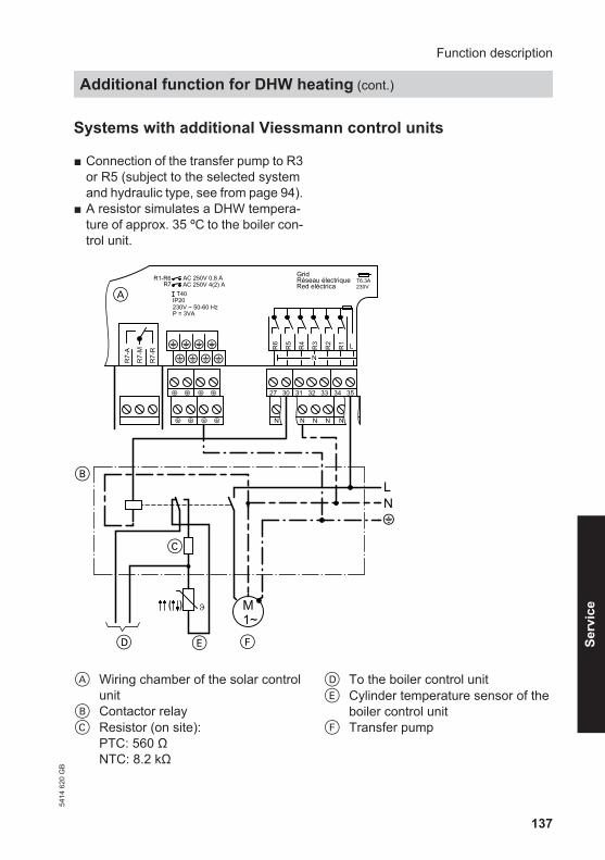
137
Systems with additional Viessmann control units
■ Connection of the transfer pump to R3or R5 (subject to the selected systemand hydraulic type, see from page 94).
■ A resistor simulates a DHW tempera-ture of approx. 35 ºC to the boiler con-trol unit.
B
C
E
L
F
N
D
M1~
?
R6
R5
R4
R3
R2
R1 L
Grid
Red eléctricaRéseau électrique T6.3A
230V
R7-
A
R7-
M
R7-
R
AC 250V 0.8 AAC 250V 4(2) A
R1-R6R7
T40IP20230V ~ 50-60 HzP = 3VA
N
N N N NN
27 30 31 32 33 34 35
A
A Wiring chamber of the solar controlunit
B Contactor relayC Resistor (on site):
PTC: 560 ΩNTC: 8.2 kΩ
D To the boiler control unitE Cylinder temperature sensor of the
boiler control unitF Transfer pump
Function description
Additional function for DHW heating (cont.)
5414
620
GB
Serv
ice

138
Make the following settings at thesolar control unit:
1. Main menu■ "System"■ "Options"
– "Add. fct."Set "Yes".
2. Select the appropriate sensor forcapturing the temperature (deliveredcondition S2) subject to which con-sumer this function should affect:
Main menu■ "System"■ "Contractor"
– "Sen. add.fct."Set value "1" to "12".
3. The transfer pump starts at an adjust-able time "t-start" (delivered condi-tion 17:00 h), if the consumer has notreached 60 ºC at least once per day.
Main menu■ "System"■ "Setting values"
– "t-start"Delivered condition 17:00 hSet the start of the additionalfunction.
Cylinder heating
■ To achieve the heating of a consumerwithin a specific range, the sensors forfunctions "Thermost. 3" and "Ther-most. 4" (in the delivered condition S5and S6) are required. These may beswitched to sensors that are already inuse (see page 161).
■ Reference parameters are the starttemperature "Th3on" and the stoptemperature "Th3off".
■ Relay R6 on:When "Th3on" is not reached at eithersensor.
■ Relay R6 off:When "Th3off" is exceeded at bothsensors.
■ In addition "Timer switch 2" (seepage 159) can be activated for thisfunction.
Make the following settings at thesolar control unit:
1. Main menu■ "System"■ "Options"
– "DHWcyl.load."Set "Yes".
2. Main menu■ "System"■ "Contractor"
– "Sen.Th3"Delivered condition 5Select sensor.
– "Sen.Th4"Delivered condition 6Select sensor.
Function description
Additional function for DHW heating (cont.)
5414
620
GB

139
3. Main menu■ "System"■ "Setting values"
– "Th3on"Delivered condition 40 °CSet a value.
– "Th3off"Delivered condition 45 °CSet a value.
Speed control
The speed control can only be enabledfor outputs R1 to R4.If variable speed control is to be enabledfor pumps connected to these outputs,these pumps must not have their ownspeed control. Set multi-stage pumps tothe required stage.
NoteWhen using pumps with their own varia-ble speed control, set "On/Off" for"Control".
When the start temperature differential"ΔTon" has been exceeded for therespective pump, that pump will be star-ted at the minimum speed.If the temperature differential rises to"ΔTset" (differential temperature for thestart of the speed control; can only beactivated for the collector circuits), thenthe speed is increased by 10% withevery rise by the value selected in"Rise".
Example:Speed control of the solar circuit pump atrelay R1
Temperature differential in K
Spee
d in
%
00
2 6 10 12 144 8
102030405060
Values in the delivered conditionΔT1on =8 KΔT1off =4 KΔT1set =10 KRise 2 K
Make the following settings at thesolar control unit:
1. Main menu■ "Solar"■ "Setting values"
– "ΔTon"Set a value.
– "ΔToff"Set a value.
– "ΔTset"Set a value.
Function description
Cylinder heating (cont.)
5414
620
GB
Serv
ice

140
2. Main menu■ "Solar"■ "Contractor"
– "Control unit"– "Rise"
Set a value.
Activating speed control
Make the following settings at thesolar control unit:
Main menu■ "Contractor"■ "Outputs"
– "Control"Set the required value (see the fol-lowing table).
Pumps Parameter "Control"Standard solar circuit pumps ■ Without individual speed control (with integral
auxiliary capacitor)"Pulse"
■ With individual speed control "ON/OFF"High efficiency pumps "ON/OFF"Pumps with PWM input
NoteUse only solar pumps, not heating circuitpumps.
■ WILO pump "PWM A"■ GRUNDFOS pump "PWM B"
Changing the minimum speed
Make the following settings at thesolar control unit:
Main menu■ "Contractor"■ "Outputs"
– "Min speed"Select the corresponding relay andset the value.
Function description
Speed control (cont.)
5414
620
GB
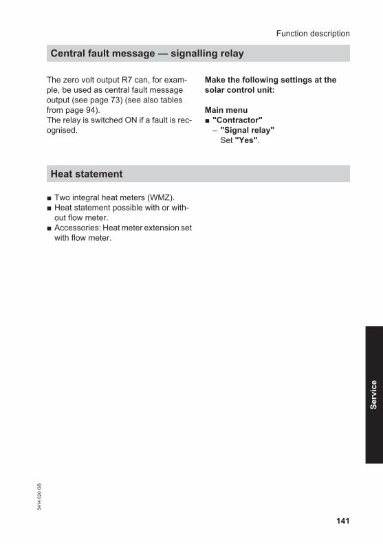
141
The zero volt output R7 can, for exam-ple, be used as central fault messageoutput (see page 73) (see also tablesfrom page 94).The relay is switched ON if a fault is rec-ognised.
Make the following settings at thesolar control unit:
Main menu■ "Contractor"
– "Signal relay"Set "Yes".
Heat statement
■ Two integral heat meters (WMZ).■ Heat statement possible with or with-
out flow meter.■ Accessories: Heat meter extension set
with flow meter.
Function description
Central fault message — signalling relay54
14 6
20 G
B
Serv
ice

142
Statement without flow meter
■ Statement:As an estimate through the differentialbetween the flow and return tempera-ture and the set throughput (see thecollector service instructions).
■ Sensor inputs S1 and S10 to S12 areprovided in the delivered condition forthis purpose.Should the flow temperature sensorhave to be located at a point wheretemperatures in excess of 95 °C couldoccur, always connect it at S1 or S9(NTC sensor with 20 kΩ) (see alsopage 69).
NoteSensors that are already installed maybe used.These must be switched over (seepage 161).
■ The statement will be calculated if theoutput set in "Relay" (see the followingsection) is activated.
Example
Use the pump on R1 and the sensors S1and S2 for the statement.
Make the following settings at thesolar control unit:
1. Main menu■ "HM"■ "Options"
– "HM 1" or "HM 2"Set "Yes".
2. Main menu■ "HM"■ "HM 1" or "HM 2"■ "Contractor"
– "Sen. Flow"Set value "1" for sensor S1.
– "Sen. Return"Set value "2" for sensor S2.
– "Frostprot.type"Set the value for the heat transfermedium selected.
– "Frost protection"Select the mixing ratio of the heattransfer medium.
– "Flow transm"Select "No".
– "Throughput"Set a value in l/min."Relay"Set value "1".
NoteTo scan the throughput volume inmenu "Manual mode" for theresponding actuator (in the examplefor relay 1) select "On". Scan thevalue at the throughput display of theSolar-Divicon.
Function description
Heat statement (cont.)
5414
620
GB

143
Statement with flow meter
Connection
B
C
D
E
V1
V2
145
145
GND
S1 S2 S3 S4 S5 S6 S7 S8 S9 S10
S11
S12
CS1
0
Imp1
Imp2
PWM
R1
PWM
R2
VBus
PWM
R3
PWM
R4
1 2 43 5 76 8 9 10 11 12 13 14 15 16 17 18 19 20
A
A Wiring chamber of the solar controlunit
B Flow temperature sensor WMZ1(collector temperature sensor)
C Return temperature sensor WMZ1
V1 Flow meter WMZ1D Flow temperature sensor WMZ2E Return temperature sensor WMZ2V2 Flow meter WMZ2
Function description
Heat statement (cont.)
5414
620
GB
Serv
ice

144
■ Statement:Through determining the temperaturedifferential between the flow andreturn temperature and the throughputcaptured by the flow meter.
■ Sensor inputs S1 and S10 to S12 areprovided in the delivered condition forthis purpose.Should the flow temperature sensorhave to be located at a point wheretemperatures in excess of 90 °C couldoccur, always connect it at S1 or S9(NTC sensor with 20 kΩ) (see alsopage 69).
NoteSensors that are already installed maybe used.These must be switched over (seepage 161).
Make the following settings at thesolar control unit:
1. Main menu■ "HM"■ "Options"
– "HM 1" or "HM 2"Set "Yes".
2. Main menu■ "HM"■ "HM 1" or "HM 2"■ "Contractor"
– "Sen. Flow"Select the sensor to be used (S1to S12).
– "Sen. Return"Select the sensor to be used (S1to S12).
– "Frostprot.type"Set the value for the heat transfermedium selected.
– "Frost protection"Select the mixing ratio of the heattransfer medium.
– "Flow transm"Set "Yes".
– "Vol./Imp."Delivered condition 1 l/ImpSet the pulse rate suitable for theflow meter (see the followingtable).
Flow meter 06 15 25 35 60Pulse rate l/imp 1 10 25 35 60Standard flow rate m3/h 0.6 1.5 2.5 3.5 6.0
Function description
Heat statement (cont.)
5414
620
GB

145
■ To record the operating values of thesolar thermal system.
■ Saving the values to the module in atext file. This may, for example, beopened in a tabular calculation pro-gram. The values can therefore alsobe visualised
■ SD module: Storage capacity ≤ 2 GB,file system FAT16
NoteNever use SD-HD modules.
Start recording
1. Insert SD module. 2. Make the following settings at thesolar control unit:
Main menu■ "SD module"
– Set "Yes".– "Interval"
Set the required recording inter-vals.
– "Linear log"Select "Yes"/"No" (see the fol-lowing table).
Function description
SD module54
14 6
20 G
B
Serv
ice

146
Parameter "Linear log"No (delivered condition): Yes:When the memory reaches its capacity limit, theoldest data will be overwritten (ring buffer).Recording continues.
Recording stops when thecapacity limit has been reached.The display shows "card full".
Terminating writing
1. Make the following setting at the solarcontrol unit:
Main menu■ "SD module"
– "Safely rem card".
2. After the display "Safely rem card"remove the module from the solarcontrol unit.
Formatting the SD module
Make the following setting at the solarcontrol unit:
Main menu■ "SD module"
– "Format"."Format" is displayed whilst theprocess runs.
The module content is deleted and themodule is formatted with the FAT16 filesystem.
Possible displays
Main menu■ "SD module"
"SD module" ExplanationNo module No module has been inserted or the module is not rec-
ognised.Record Data recording active.Time rem Number of recording days for which the module still
offers enough capacity.
Function description
SD module (cont.)
5414
620
GB

147
Messages
Messages that are only displayed if thesolar control unit displays "!SD-CardError" or "SD Error" in case the systemhas developed a fault (see page 89).
Main menu■ "Messages"
– "!SD-Card Error"/"SD Error".
"Messages" Cause Remedy!File system The inserted module is not
formatted with the FAT16 filesystem.
Format the SD module.
! Incorrect card Incorrect module type inser-ted orMemory capacity > 2 GB.
Never insert SD-HD modules.Insert module with memorycapacity ≤ 2 GB.
-! Write fault Error during writing to themodule.
Replace module.
! Write protect The module is write protec-ted.
Disable the write protection ofthe module.
Relay kick
The pumps/valves are started at anadjustable time for 10 s to prevent themfrom seizing up.
Make the following settings at thesolar control unit:
Main menu■ "Contractor"
– "Outputs"– "Relay kick"
Set "Yes".– "Time"
Select the time for the relay kick.
Function description
SD module (cont.)
5414
620
GB
Serv
ice
148
When ordering spare partsQuote the part and serial no. (see typeplate) and the position no. of the requiredpart (as per this parts list).Obtain standard parts from your localsupplier.
Parts010 Collector temperature sensor020 Cylinder temperature sensor030 Strain relief pack and fuse040 Fuse, 6.3 A (slow) (5 pce)050 Installation and service instructions060 Operating instructions
Parts list
Parts list
5414
620
GB

149
250 47
204
Rated voltage 230 V∼Rated frequency 50 HzRated current 6APower consumption 6 W
(in standby mode 0.9 W)Protection class IIProtection IP 20 D to EN 60529, ensure through design/instal-
lationFunction Type 1 B to EN 60730-1Permiss. ambient temperature ■ during operation 0 to +40 °C
Installation in living spaces or boiler rooms (stand-ard ambient conditions)
■ during storage and transport −20 to +65 °C
Rated relay output load breakingcapacity at 230 V∼■ Semi-conductor
relay 1 to 60.8 A
■ Relay 7 4 (2) A∼■ Total max. 6 A
Specification
Specification54
14 6
20 G
B
Serv
ice

150
Main menuActual valuesMessagesSolarSystemHM
Manual modeOperator code
Solarback
StatementOptionsExperts
Systemback
OptionsExperts
HM
Setting values
Setting values
back
Expertsback
AB
C
E
F
G
K
H
D
SensorsOutputs
Signal realyYesYesΔT too high
Night changeNo
Experts
SD module
Clock
OptionsHM 2HM 1
L
DisplayLanguage
A See page 85.B See page 87, 89 and 147.C See from page 151.D See page 86.E See from page 158.
F See from page 163.G See from page 164.H See page 80.K See page 84.L See page 164.
Appendix
Menu structure overview
5414
620
GB

151
The parameter display depends on thesystem equipment level.
Menu "Solar"
Setting values Solar set-ting:
Description Deliveredcondition
Setting range Set value
Tcylset Set temperature con-sumer 1 (seepage 117)
60 °C 4 to 90 °C
Tcyl set1 At Cyl set = "Yes":Set temperature 1(see page 135)
60 °C 4 to 90 °C
Tcyl set2 At Cyl set = "Yes":Set temperature 2(see page 135)
60 °C 4 to 90 °C
Tcyl2 set Set temperature con-sumer 2
60 °C 4 to 90 °C
Tcyl2 set 1 At Cyl set = "Yes":Set temperature 1(see page 135)
60 °C 4 to 90 °C
Tcyl2 set 2 At Cyl set = "Yes":Set temperature 2(see page 135)
60 °C 4 to 90 °C
Tcyl3 set Set temperature con-sumer 3
60 °C 4 to 90 °C
Tcyl3 set 1 At Cyl set = "Yes":Set temperature 1(see page 135)
60 °C 4 to 90 °C
Tcyl3 set 2 At Cyl set = "Yes":Set temperature 2(see page 135)
60 °C 4 to 90 °C
Tcyl4 set Set temperature con-sumer 4
60 °C 4 to 90 °C
Tcyl4 set 1 At Cyl set = "Yes":Set temperature 1(see page 135)
60 °C 4 to 90 °C
Tcyl4 set 2 At Cyl set = "Yes":Set temperature 2(see page 135)
60 °C 4 to 90 °C
Appendix
Overview of system parameters54
14 6
20 G
B
Serv
ice

152
Setting values Solar set-ting:
Description Deliveredcondition
Setting range Set value
ΔTon Start temperature dif-ferential for solar cir-cuit pump*4
8 K 1.5 to 20 K
ΔToff Stop temperature dif-ferential for the solarcircuit pump*5
4 K 1 to 19.5 K
ΔTset Differential tempera-ture for the start ofspeed regulation (seepage 139)
10 K 2 to 30 K
ΔT2on Start temperature dif-ferential for con-sumer 2*4
8 K 1.5 to 20 K
ΔT2off Stop temperature dif-ferential for con-sumer 2*5
4 K 1 to 19.5 K
ΔT2set Differential tempera-ture for the start ofspeed regulation (seepage 139)
10 K 2 to 30 K
ΔT3on Start temperature dif-ferential for con-sumer 3*4
8 K 1.5 to 20 K
ΔT3off Stop temperature dif-ferential for con-sumer 3*5
4 K 1 to 19.5 K
ΔT3set Differential tempera-ture for the start ofspeed regulation (seepage 139)
10 K 2 to 30 K
ΔT4on Start temperature dif-ferential for con-sumer 4*4
8 K 1.5 to 20 K
ΔT4off Stop temperature dif-ferential for consumer4*5
4K 1 to 19.5 K
*4 "ΔTon" can be at least 0.5 K above "ΔToff".*5 "ΔToff" can be at least 0.5 K below "ΔTon".
Appendix
Overview of system parameters (cont.)
5414
620
GB

153
Setting values Solar set-ting:
Description Deliveredcondition
Setting range Set value
ΔT4set Differential tempera-ture for the start ofspeed regulation (seepage 139)
10 K 2 to 30 K
Surplus cyl Consumer for heattransfer
1 1 to 4
Priority Cyl1 Sequence in which theconsumers are to beheated up (seepage 117)
1 Subject to the num-ber of consumersfrom 1 to 4
Priority Cyl2 2 Priority Cyl3 3 Priority Cyl4 4 HE ΔTon Start temperature dif-
ferential for the secon-dary pump of the ext.heat exchanger*4 (seepage 124)
5 K 1 to 19.5 K
HE ΔToff Stop temperature dif-ferential for the secon-dary pump of the ext.heat exchanger*5 (seepage 124)
3 K 1.5 to 20 K
SC Byp. Insolation threshold*6
(See page 120and 121).
200 W/m2 100 to 500 W/m2
Interval Interval for intervalfunction (seepage 127)
30 min 1 to 60 min
Tcolset Set collector tempera-ture in conjunctionwith activating thefunction "Targettemp." (seepage 130)
65 °C 20 to 110 °C
*4 "ΔTon" can be at least 0.5 K above "ΔToff".*5 "ΔToff" can be at least 0.5 K below "ΔTon".*6 Vitosol-F: 210 W/m2
Vitosol -T: 130 W/m2
Appendix
Overview of system parameters (cont.)
5414
620
GB
Serv
ice
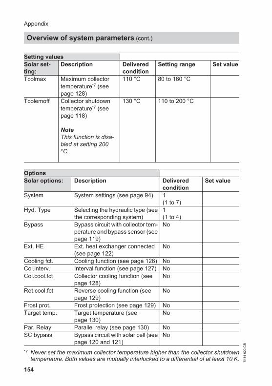
154
Setting values Solar set-ting:
Description Deliveredcondition
Setting range Set value
Tcolmax Maximum collectortemperature*7 (seepage 128)
110 °C 80 to 160 °C
Tcolemoff Collector shutdowntemperature*7 (seepage 118)
NoteThis function is disa-bled at setting 200°C.
130 °C 110 to 200 °C
Options Solar options: Description Delivered
conditionSet value
System System settings (see page 94) 1(1 to 7)
Hyd. Type Selecting the hydraulic type (seethe corresponding system)
1(1 to 4)
Bypass Bypass circuit with collector tem-perature and bypass sensor (seepage 119)
No
Ext. HE Ext. heat exchanger connected(see page 122)
No
Cooling fct. Cooling function (see page 126) No Col.interv. Interval function (see page 127) No Col.cool.fct Collector cooling function (see
page 128)No
Ret.cool.fct Reverse cooling function (seepage 129)
No
Frost prot. Frost protection (see page 129) No Target temp. Target temperature (see
page 130)No
Par. Relay Parallel relay (see page 130) No SC bypass Bypass circuit with solar cell (see
page 120 and 121)No
*7 Never set the maximum collector temperature higher than the collector shutdowntemperature. Both values are mutually interlocked to a differential of at least 10 K.
Appendix
Overview of system parameters (cont.)
5414
620
GB

155
Options Solar options: Description Delivered
conditionSet value
Heat.interr. Suppression of reheating by theboiler (see page 131)
No
Cyl.2 on Cylinder 2 on (see page 134) Yes Cyl.3 on Cylinder 3 on (see page 134) Yes Cyl.4 on Cylinder 4 on (see page 134) Yes Overheat Only in conjunction with systems
3 to 7:Heat transfer if "Tcyl set" hasbeen reached.
No
Contractor Solar contrac-tor:
Description Deliveredcondition
Setting range Setvalue
TColmin Minimum collectortemperature, collectorarray 1 (seepage 135)
10 °C 10 to 90 °C
TCol2min Minimum collectortemperature, collectorarray 2 (seepage 135)
10 °C 10 to 90 °C
ΔT-Cylset Hysteresis for set tem-perature "Tcyl set"(see page 151)
2K 0.5 to 5 K
ΔTCyl2set Hysteresis for set tem-perature"Tcyl2 set"(see page 151)
2K 0.5 to 5 K
ΔTCyl3set Hysteresis for set tem-perature"Tcyl3 set"(see page 151)
2K 0.5 to 5 K
ΔTCyl4set Hysteresis for set tem-perature"Tcyl4 set"(see page 151)
2K 0.5 to 5 K
Cyl set Heating to the secondset temperature, con-sumer 1(see page 135)
No
Appendix
Overview of system parameters (cont.)
5414
620
GB
Serv
ice

156
Contractor Solar contrac-tor:
Description Deliveredcondition
Setting range Setvalue
Cyl2 set Heating to the secondset temperature, con-sumer 2(see page 135)
No
Cyl3 set Heating to the secondset temperature, con-sumer 3(see page 135)
No
Cyl4 set Heating to the secondset temperature, con-sumer 4(see page 135)
No
Sen.cyl set Reference sensor forstopping the solar cir-cuit pump, subject toTcyl set (no influenceon the differential tem-perature control). Forexample, one sensorin the upper area of theconsumer.
2 1 to 12
Sen.cyl2 set See above. 4 1 to 12 Sen.cyl4 set See above. 5 1 to 12 Sen.cyl4 set See above. 6 1 to 12 t-stop Pump run break dura-
tion, cycle pause time(see page 135)
2 min 1 to 60 min
t-circ. Interruption interval,cyclical heating (seepage 135)
15 min 1 to 60 min
ΔT Col Collector temperatureincrease (seepage 135)
2 K 1.0 to 10.0 K
Appendix
Overview of system parameters (cont.)
5414
620
GB

157
Contractor Solar contrac-tor:
Description Deliveredcondition
Setting range Setvalue
Int time In case the intervalfunction has been acti-vated:Time when the solarcircuit pump runsaccording to the selec-ted interval and timeframe (see page 127)
30 s 5 to 500 s
Int ON In case the intervalfunction has been acti-vated:Start of the intervalfunction (seepage 127)
07:00to19:00
00:00to23:45
Int OFF In case the intervalfunction has been acti-vated:End of the intervalfunction (seepage 127)
07:00to19:00
00:00to23:45
Suppr.heat cyl In case of activatedbooster suppression:Consumer to whichthis function shouldapply
Cyl.1 1 to 4
HE-cylinder Consumer that is to beheated via the externalheat exchanger
1 1 to 55: all consumers
Sen.HE.flow VL Sensor that should beused for the function"Ext. heat exchanger"(see page 122)
3 1 to 12
Sen. bypass Sensor that should beused for the bypassfunction (seepage 119)
3 1 to 12
Bypass Bypass circuit hydraul-ics (see page 119and 121)
Valve Valve/pump
Appendix
Overview of system parameters (cont.)
5414
620
GB
Serv
ice
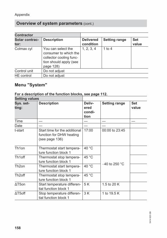
158
Contractor Solar contrac-tor:
Description Deliveredcondition
Setting range Setvalue
Colmax cyl You can select theconsumer to which thecollector cooling func-tion should apply (seepage 128)
1, 2, 3, 4 1 to 4
Control unit Do not adjustHE control Do not adjust
Menu "System"
For a description of the function blocks, see page 112.Setting values Sys. set-ting:
Description Deliv-eredcondi-tion
Setting range Setvalue
Time — — — —Date — — — t-start Start time for the additional
function for DHW heating(see page 136)
17:00 00:00 to 23:45
Th1on Thermostat start tempera-ture function block 1
40 °C
−40 to 250 °C
Th1off Thermostat stop tempera-ture function block 1
45 °C
Th2on Thermostat start tempera-ture function block 1
40 °C
Th2off Thermostat stop tempera-ture function block 1
45 °C
ΔT5on Start temperature differen-tial function block 1
5 K 1.5 to 20 K
ΔT5off Stop temperature differen-tial function block 1
3 K 1 to 19.5 K
Appendix
Overview of system parameters (cont.)
5414
620
GB

159
Setting values Sys. set-ting:
Description Deliv-eredcondi-tion
Setting range Setvalue
Time switch1
Period function block 1 00:00 00:00 to 23:00
t1–ont1–offt2–ont2–offt3–ont3–offTh3on Thermostat start tempera-
ture function block 240 °C
−40 to 250 °C
Th3off Thermostat stop tempera-ture function block 2
45 °C
Th4on Thermostat start tempera-ture function block 2
40 °C
Th4off Thermostat stop tempera-ture function block 2
45 °C
ΔT6on Start temperature differen-tial function block 2
5 K 1.5 to 20 K
ΔT6off Stop temperature differen-tial function block 2
3 K 1 to 19.5 K
Time switch2
Period function block 2 00:00 00:00 to 23:00
t1–ont1–offt2–ont2–offt3–ont3–offTh5on Thermostat start tempera-
ture function block 340 °C
−40 to 250 °C
Th5off Thermostat stop tempera-ture function block 3
45 °C
Th6on Thermostat start tempera-ture function block 3
40 °C
Th6off Thermostat stop tempera-ture function block 3
45 °C
Appendix
Overview of system parameters (cont.)
5414
620
GB
Serv
ice

160
Setting values Sys. set-ting:
Description Deliv-eredcondi-tion
Setting range Setvalue
ΔT7on Start temperature differen-tial function block 3
5 K 1.5 to 20 K
ΔT7off Stop temperature differen-tial function block 3
3 K 1 to 19.5 K
Time switch3
Period function block 3 00:00 00:00 to 23:00
t1–ont1–offt2–ont2–offt3–ont3–off
For a description of the function blocks, see page 112.Options Sys. options: Description Delivered
conditionSet value
Add. fct. Additional function forDHW heating (seepage 136)
No
DHWcyl.load. Cylinder heating (seepage 138)
No
Thermost. 1 Thermostat function 1,function block 1
No
Thermost. 2 Thermostat function 2,function block 1
No
ΔT Fct5 ΔT5 differential tempera-ture control, functionblock 1
No
Time switch 1 Time switch 1, functionblock 1
No
Thermost. 3 Thermostat function 3,function block 2
No
Thermost. 4 Thermostat function 4,function block 2
No
Appendix
Overview of system parameters (cont.)
5414
620
GB

161
Options Sys. options: Description Delivered
conditionSet value
ΔT Fct6 ΔT6 differential tempera-ture control, functionblock 2
No
Time switch 2 Time switch 2, functionblock 2
No
Thermost. 5 Thermostat function 5,function block 3
No
Thermost. 6 Thermostat function 6,function block 3
No
ΔT Fct7 ΔT7 differential tempera-ture control, functionblock 3
No
Time switch 3 Time switch 3, functionblock 3
No
Reference sensors for the required functions can be determined in the following sub-menu. All sensors that already have a function in the system are available for this.The sensors are switched.
For a description of the function blocks, see page 112.Contractor Sys.contractor: Description Delivered
conditionSettingrange
Setvalue
Sen. add.fct. Reference sensor for theadditional function forDHW heating (seepage 136)
2 1 to 12
Sen.Th1 Reference sensor for ther-mostat function 1, functionblock 1
3 1 to 12
Sen.Th2 Reference sensor for ther-mostat function 2, functionblock 1
4 1 to 12
Sen1 ΔT5Fct Reference sensor for dif-ferential temperature con-trol, function block 1
3 1 to 12
Sen2 ΔT5Fct Reference sensor for dif-ferential temperature con-trol, function block 1
4 1 to 12
Appendix
Overview of system parameters (cont.)
5414
620
GB
Serv
ice

162
Contractor Sys.contractor: Description Delivered
conditionSettingrange
Setvalue
Sen.Th3 Reference sensor for ther-mostat function 3, functionblock 2
5 1 to 12
Sen.Th4 Reference sensor for ther-mostat function 4, functionblock 2
6 1 to 12
Sen1 ΔT6Fct Reference sensor for dif-ferential temperature con-trol, function block 2
5 1 to 12
Sen2 ΔT6Fct Reference sensor for dif-ferential temperature con-trol, function block 2
6 1 to 12
Sen.Th5 Reference sensor for ther-mostat function 5, functionblock 3
7 1 to 12
Sen.Th6 Reference sensor for ther-mostat function 6, functionblock 3
8 1 to 12
Sen1 ΔT7Fct Reference sensor for dif-ferential temperature con-trol, function block 3
7 1 to 12
Sen2 ΔT7Fct Reference sensor for dif-ferential temperature con-trol, function block 3
8 1 to 12
Control ΔT5 Pump speed control forthe ΔT5 control(ΔTset = 10 K)
■ Rise 2 1 to 20
Appendix
Overview of system parameters (cont.)
5414
620
GB

163
Menu "HM" (heat meter)
Options HM options: Description Delivered
conditionSet value
HM 1 Heat meter with state-ment calculation (seepage 141)
No
HM 2 Heat meter with state-ment calculation (seepage 141)
No
For a description of the function, see page 141.Contractor HM 1 contractor:/HM 2 contractor:
Description Deliveredcondition
Settingrange
Setvalue
Sens. flow Flow temperature sen-sor
1 1 to 12
Sen. Return Return temperature sen-sor
10 1 to 12
Frostprot.type 0 Water1 Propylene glycol2 Ethylene glycol3 Viessmann heat
transfer medium
3 0 to 3
Frost protection Will only be displayed if aheat transfer mediumthat can be mixed hasbeen entered
40 % 20to70 %
Flow transm If a flow meter is instal-led
No —
Vol./Imp. Will only be displayed if"Flow transm" hasbeen set to "Yes".The throughput capturedby the flow meter (seepage 143)
1l/Imp 1to99 l/Imp.
Appendix
Overview of system parameters (cont.)
5414
620
GB
Serv
ice

164
Contractor HM 1 contractor:/HM 2 contractor:
Description Deliveredcondition
Settingrange
Setvalue
Throughput Will only be displayed if"Flow transm" hasbeen set to "No":Throughput (seepage 142)
5 l 1to20 l/min
Relay Relay to which the corre-sponding consumer isconnected
1 1 to 7
Menu "SD module"
SD module: Description Deliveredcondition
Settingrange
Set value
Safely rem card Terminating writing Format Format the SD module Interval Writing interval 20 min 1 to 20 min Linear log Data ring buffer off No
Menu "Contractor"
Contractor: Description Deliv-ered con-dition
Settingrange
Set value
ΔT too high See page 89 Yes Night change If gravity results in a
recirculation between23:00 and 05:00 h, amessage will beissued (see page 87and 89)
Yes
Signal relay Relay 7 is used assignalling relay incase of faults (seepage 141)
No
Sensors ■ Solarcell type ID letter of the solar
cellE A,B, C, D, E,
G, H, J, K
■ Match solarcells Only for service personnel!
Appendix
Overview of system parameters (cont.)
5414
620
GB

165
Contractor: Description Deliv-ered con-dition
Settingrange
Set value
■ SC offset Do not adjust ■ Temp.units Temperature unit °C
Celsius°FFahrenheit
■ Sensor 1 Sensor matching 0 K −5 K to 5 K ■ Sensor 2 Sensor matching 0 K −5 K to 5 K ■ Sensor 3 Sensor matching 0 K −5 K to 5 K ■ Sensor 4 Sensor matching 0 K −5 K to 5 K ■ Sensor 5 Sensor matching 0 K −5 K to 5 K ■ Sensor 6 Sensor matching 0 K −5 K to 5 K ■ Sensor 7 Sensor matching 0 K −5 K to 5 K ■ Sensor 8 Sensor matching 0 K −5 K to 5 K ■ Sensor 9 Sensor matching 0 K −5 K to 5 K ■ Sensor 10 Sensor matching 0 K −5 K to 5 K ■ Sensor 11 Sensor matching 0 K −5 K to 5 K ■ Sensor 12 Sensor matching 0 K −5 K to 5 K Outputs ■ Min speed 1 Minimum speed of
the pump at R130 % 30 to 100 %
■ Min speed 2 Minimum speed ofthe pump at R2
30 % 30 to 100 %
■ Min speed 3 Minimum speed ofthe pump at R3
30 % 30 to 100 %
■ Min speed 4 Minimum speed ofthe pump at R4
30 % 30 to 100 %
■ Relay kick The pumps are star-ted at an adjustabletime for 10 s to pre-vent them from seiz-ing up
No
■ Time Time for relay kick ■ Control 1 See the table on
page 69ON/OFF
■ Control 2 See the table onpage 69
ON/OFF
■ Control 3 See the table onpage 69
ON/OFF
■ Control 4 See the table onpage 69
ON/OFF
■ VBus Activating the V BUS Yes
Appendix
Overview of system parameters (cont.)
5414
620
GB
Serv
ice

166
Contractor: Description Deliv-ered con-dition
Settingrange
Set value
Clock ■ KMBus time Adopting the time
from the boiler controlunit via KM BUS
Yes
■ Auto summer Automatic change-over summer/winter-time(Only if for KM BUStime "No")
Yes
■ Time UTC(Time at the zeromeridian, i.e.CET less 1 h)
Time for the summer/wintertime change-over(Only if for KM BUStime "No")
Display ■ Inverted White
script on ablackback-ground
Black scripton a whitebackground
■ Lighting Strength of the dis-play backlighting
100 50 to 100
Language See page 81 — —
PCBs
Replace the PCB in the stated boilercontrol units in conjunction with the fol-lowing functions:■ Suppression of reheating by the boiler■ Auxiliary function for DHW heating,
achieved by the solar control unit
Appendix
Overview of system parameters (cont.)
5414
620
GB

167
Control unit Electronics PCBVitotronic 200, type KW1,part no. 7450 351, 7450 740
Part no. 7828 192
Vitotronic 200, type KW2,part no. 7450 352, 7450 750Vitotronic 300, type KW3,part no. 7450 353, 7450 760Vitotronic 200, type GW1,part no. 7143 006
Part no. 7828 193
Vitotronic 300, type GW2,Part no. 7143 156Vitotronic 333, type MW1,Part no. 7143 421
Part no. 7828 194
Appendix
PCBs (cont.)
5414
620
GB
Serv
ice

168
We, Viessmann Werke GmbH&Co KG, D-35107 Allendorf, declare as sole respon-sible body, that the product Vitosolic 200 complies with the following standards:
EN 55 014-1EN 60 730
In accordance with the following Directives, this product is designated with _:
2004/108/EC2006/95/EC
Allendorf, 1 May 2009 Viessmann Werke GmbH&Co KG
pp. Manfred Sommer
Certificates
Declaration of conformity
5414
620
GB

169
AActivating speed control...................140Additional function for DHWheating.....................................136, 160Adjusting the display..........................82Amount of heat■ reset................................................86Anti-scalding protection........................7Applicability......................................172Automatic mode.................................79Automatic operation...........................84
BBooster suppression........................131Bypass.............................................118
CCentral fault message......................141Central fault message facility.............73Changing the fuse..............................93Changing the minimum speed.........140Changing the speed.........................140Checking actuators............................84Checking relays (actuators)...............92Checking sensors..............................92Collector cooling function.........128, 154Collector emergency stop................118Collector temperature sensor.............74Commissioning..................................79Confirmation of a value input.............79Controls..............................................79Cooling function.......................126, 154Cyclical heating................................135Cylinder heating...............................138Cylinder priority control....................117Cylinder temperature limit................117Cylinder temperature sensor..............74
DDeclaration of conformity.................168
EEntering the operator code................80Equipotential bonding..........................7External heatexchanger................122, 154, 163, 164
FFault messages..................................88Fitting the solar control unit................67Frost protection................................154Frost protection function..................129Function blocks................................112Function description...........................94
HHeat meter extension set.................143Heat statement.................................141High limit safety cut-out......................71Hydraulic types..................................94
IInsolation intensity.............................85Insolation threshold..........................153Interval function................127, 153, 154
LLanguage selection............................81
MManual mode.....................................84Maximum collector temperaturelimit...................................................128Menu■ Contractor.....................................164■ HM (heat meter)...........................163■ SD module....................................164■ Solar.............................................151■ System..........................................158Menu structure.................................150Menu structure overview..................150Messages...........................................88Minimum collector temperature limit 135
Keyword index
Keyword index54
14 6
20 G
B

170
NNavigation through the menu.............79
OOverview of electrical connections.....68
PParallel relay............................130, 154Parameter■ setting.............................................82Parts list...........................................148Possible pumps..................................69Power supply.....................................77Pump kick........................................147Pumps................................................69
RReference sensors...........................112Relay kick.........................................147Relay test...........................................84Resetting parameters into their deliveredstate...................................................84Reverse cooling function..........129, 154
SScanning■ Operating states.............................85■ Pump speed...................................85■ Statement values............................85■ Temperatures.................................85Scanning messages...........................87Scanning operating states.................85Scanning pump speed.......................85Scanning temperatures......................85Scanning the hardware version.........87Scanning the heat yield......................86Scanning the software version...........87
Scanning the statement.....................85SD module.......................................145Selecting the hydraulic type...............82Selecting the system..........................82Setting pump parameters...................83Setting the time..................................82Signalling relay.................................141Solar cell............................................76Solar circuit pump..............................69Spare fuse..........................................93Speed control...................................139Start and stop temperature forthermostats......................................158Start time for additional function for DHWheating.............................................158Summer/wintertime changeover......166Suppression of reheating.................155Switching the control unit ON.............79Switching the power ON....................79Switch sensors.................................161System parameters■ Overview.......................................151Systems.............................................94
TTarget temperature..........................130Temperature sensors.........................75Test values.........................................85Time.................................................166Time frame for time switch...............159Time switch......................................160Time via KM BUS.............................166
UUtilisation of excess heat.................134
Keyword index
Keyword index (cont.)
5414
620
GB

171
5414
620
GB

172
Applicability
Applicable for the Vitosolic 200, type SD4Part no. 7418 202
Viessmann LimitedHortonwood 30, TelfordShropshire, TF1 7YP, GBTelephone: +44 1952 675000Fax: +44 1952 675040E-mail: [email protected]
Viessmann Werke GmbH&Co KGD-35107 AllendorfTelephone: +49 6452 70-0Fax: +49 6452 70-2780www.viessmann.com
5414
620
GB
Sub
ject
to te
chni
cal m
odifi
catio
ns.
Prin
ted
on e
nviro
nmen
tally
frie
ndly
,ch
lorin
e-fre
e bl
each
ed p
aper


