Embed Size (px)
Citation preview
Vital-Sim LCP Gateway Guide
April 24, 2015 ©Vital-Sim Inc. 1
LCP Gateway Guide Target Audience This guide is intended for first time or new users of the Vital-Sim LCP Gateway utility. It is assumed that
the reader is familiar with Vital-Sim and Railroad Signal Engineering practices and conventions. This
guide is not intended to be complete documentation for Vital-Sim. There are many features and options
that a user will learn about and become familiar with through ongoing use of the product.
LCP Gateway Vital-Sim provides that ability to simulate locations/configurations with multiple vital logic processors.
The LCP Gateway utility enables the user to connect and use a Local Control Panel or CTC Office
application to unit test or system integration test with a location simulated in Vital-Sim.
Summary of Features:
Harmon LCP and GENISYS Master/Slave serial protocols supported
Communication options:
- serial COM/RS232 devices
- Current loop via RS-232/Current loop adapter
- UDP over network
Multiple concurrent instances of LCP Gateway permitted
Local, Gateway and Remote Control modes are provided.
Compatible with Virtual Com Devices
Session communication log files are generated
Legacy Harmon HLC LCP supported via separate RS232-current loop adapter:
Vital-Sim LCP Gateway Guide
April 24, 2015 ©Vital-Sim Inc. 2
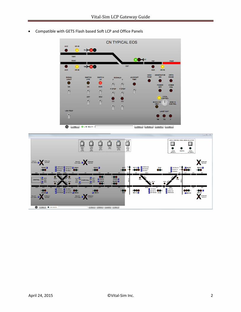
Compatible with GETS Flash based Soft LCP and Office Panels
Vital-Sim LCP Gateway Guide
April 24, 2015 ©Vital-Sim Inc. 3
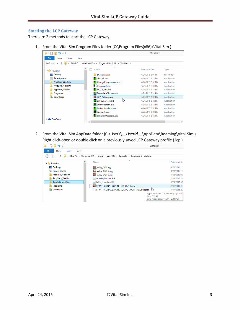
Starting the LCP Gateway
There are 2 methods to start the LCP Gateway:
1. From the Vital-Sim Program Files folder (C:\Program Files(x86)\Vital-Sim )
2. From the Vital-Sim AppData folder (C:\Users\__UserId__\AppData\Roaming\Vital-Sim )
Right click-open or double click on a previously saved LCP Gateway profile (.lcpj)
Vital-Sim LCP Gateway Guide
April 24, 2015 ©Vital-Sim Inc. 4
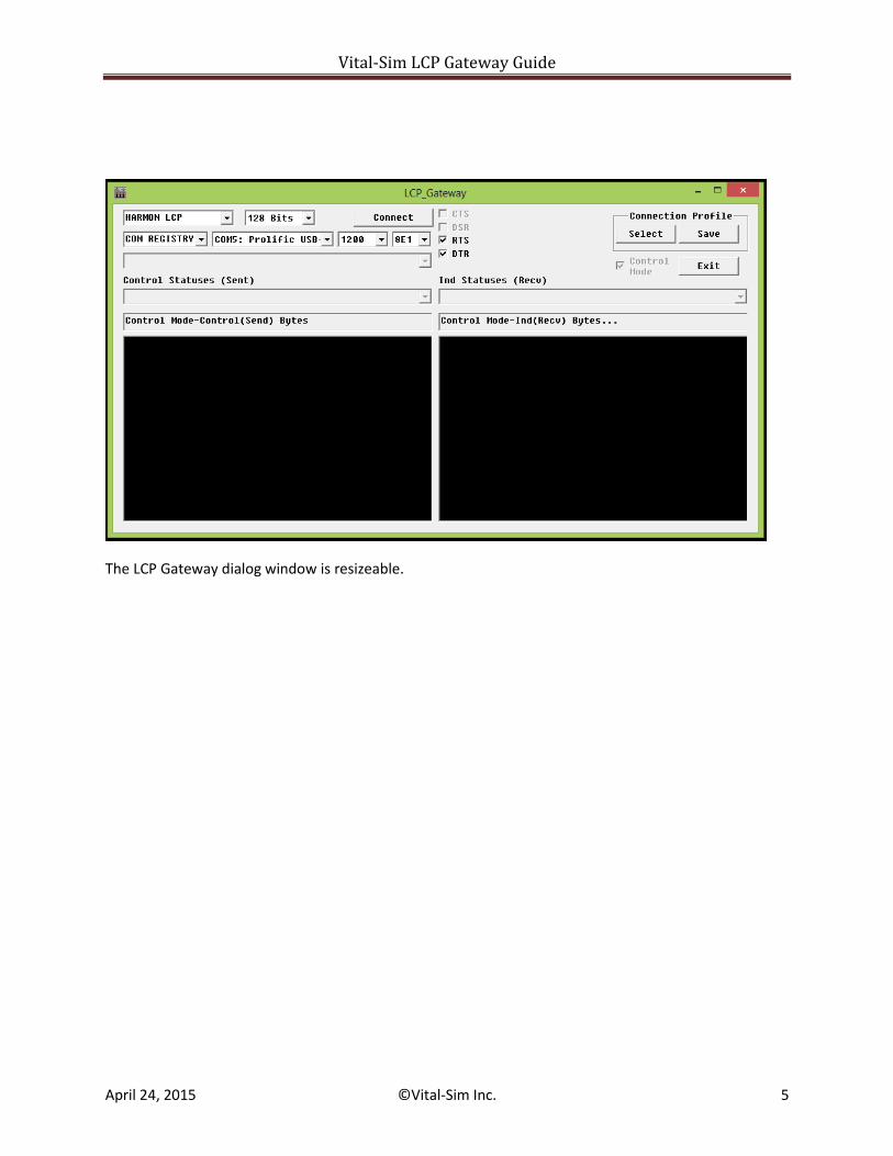
LCP Gateway Dialog Description
The LCP Gateway Dialog provides the following elements:
1. Protocol Selection (Harmon LCP, GENISYS)
2. For Harmon LCP Protocol:
- Message Size Selector (default 128 bits)
3. For Genisys Protocol (Master/Slave):
- Station Selector (default Station 01)
- Poll Rate Selector (1sec, 500msec, 200msec) – Control Mode only
4. Connection type selection.
- Serial COM 1-20
- Serial COM Registry (for COM devices recorded in Windows Registry)
- Network UDP
5. For Serial COM option:
- COM device selector.
- COM baud rate selector.
- COM device parameter setup (Baud/Parity)
- Harmon LCP default -1200 8E1 (8 Bits, Even Parity, 1 Stop)
- Genisys default – 9600 8N1 (8Bits, No Parity, 1 Stop)
- RS-232 control pins RTS, DTR
(may be set before starting a connection – default is to select both RTS and DTR)
- RS-232 status pins CTS, DSR
(indication for active serial connections)
6. For Network UDP option:
- IP Address selector
- Port selector
7. Application Selector – populated based on current available applications running in
Vital-Sim
8. “Control” Selector (e.g., Serial channels associated with selected application)
9. “Indicator” Selector (e.g., Serial channels associated with selected application)
10. “Control” tag list
11. “Indicator” tag list
12. Last “Received Bytes” and “Sent Bytes” message (hexadecimal)
13. “Profile” select button – allows selection of previously saved LCP Gateway session
14. “Save” profile button – allows saving LCP Gateway session parameters
15. Control Mode Checkbox
16. For Gateway Mode:
- “Start”/”Stop” button
17. For Control Mode:
- “Connect”/”Disconnect” button
Vital-Sim LCP Gateway Guide
April 24, 2015 ©Vital-Sim Inc. 5
The LCP Gateway dialog window is resizeable.
Vital-Sim LCP Gateway Guide
April 24, 2015 ©Vital-Sim Inc. 6
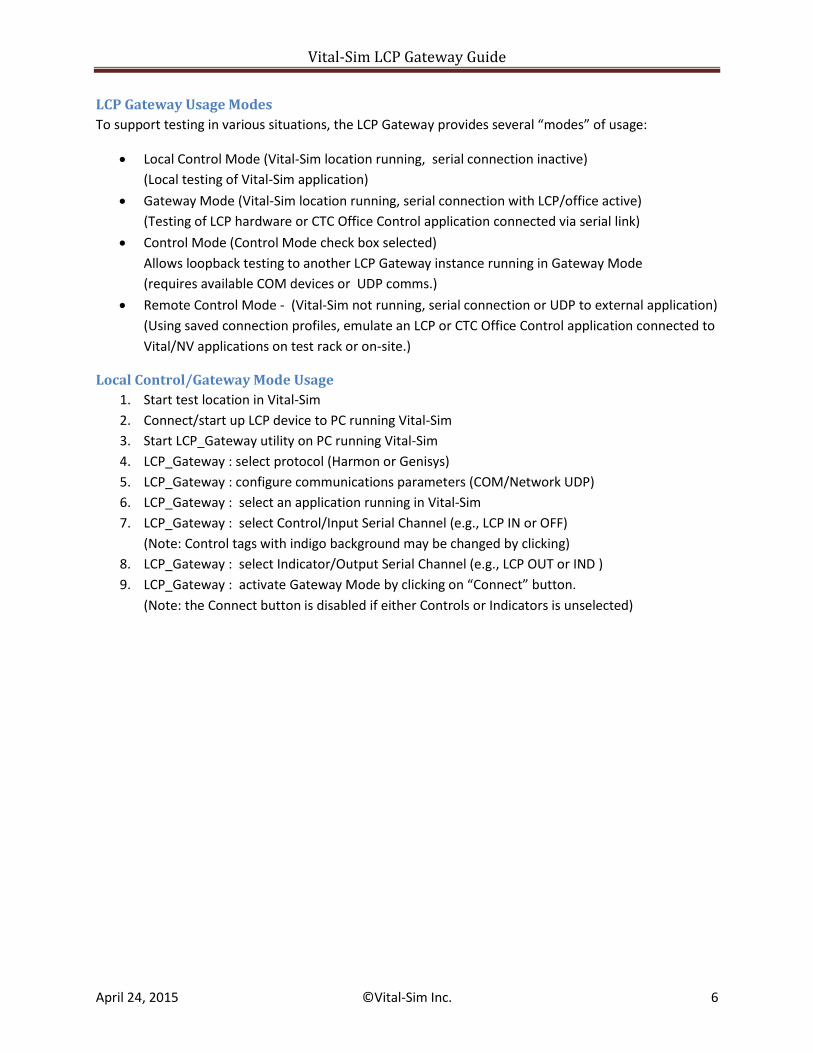
LCP Gateway Usage Modes
To support testing in various situations, the LCP Gateway provides several “modes” of usage:
Local Control Mode (Vital-Sim location running, serial connection inactive)
(Local testing of Vital-Sim application)
Gateway Mode (Vital-Sim location running, serial connection with LCP/office active)
(Testing of LCP hardware or CTC Office Control application connected via serial link)
Control Mode (Control Mode check box selected)
Allows loopback testing to another LCP Gateway instance running in Gateway Mode
(requires available COM devices or UDP comms.)
Remote Control Mode - (Vital-Sim not running, serial connection or UDP to external application)
(Using saved connection profiles, emulate an LCP or CTC Office Control application connected to
Vital/NV applications on test rack or on-site.)
Local Control/Gateway Mode Usage
1. Start test location in Vital-Sim
2. Connect/start up LCP device to PC running Vital-Sim
3. Start LCP_Gateway utility on PC running Vital-Sim
4. LCP_Gateway : select protocol (Harmon or Genisys)
5. LCP_Gateway : configure communications parameters (COM/Network UDP)
6. LCP_Gateway : select an application running in Vital-Sim
7. LCP_Gateway : select Control/Input Serial Channel (e.g., LCP IN or OFF)
(Note: Control tags with indigo background may be changed by clicking)
8. LCP_Gateway : select Indicator/Output Serial Channel (e.g., LCP OUT or IND )
9. LCP_Gateway : activate Gateway Mode by clicking on “Connect” button.
(Note: the Connect button is disabled if either Controls or Indicators is unselected)
Vital-Sim LCP Gateway Guide
April 24, 2015 ©Vital-Sim Inc. 7
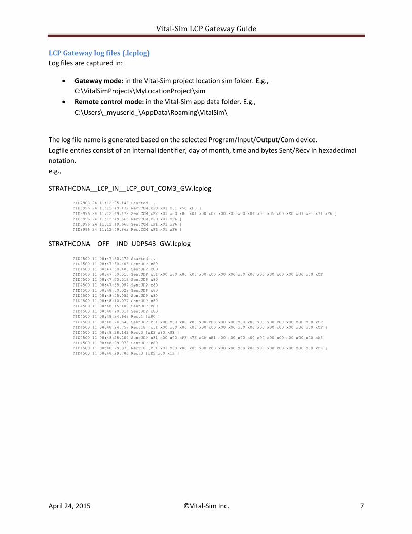
LCP Gateway log files (.lcplog)
Log files are captured in:
Gateway mode: in the Vital-Sim project location sim folder. E.g.,
C:\VitalSimProjects\MyLocationProject\sim
Remote control mode: in the Vital-Sim app data folder. E.g.,
C:\Users\_myuserid_\AppData\Roaming\VitalSim\
The log file name is generated based on the selected Program/Input/Output/Com device.
Logfile entries consist of an internal identifier, day of month, time and bytes Sent/Recv in hexadecimal
notation.
e.g.,
STRATHCONA__LCP_IN__LCP_OUT_COM3_GW.lcplog
TID7908 24 11:12:05.148 Started...
TID8996 24 11:12:49.472 RecvCOM[xFD x01 x81 x50 xF6 ]
TID8996 24 11:12:49.472 SentCOM[xF2 x01 x00 x00 x01 x00 x02 x00 x03 x00 x04 x00 x05 x00 xE0 x01 x91 x71 xF6 ]
TID8996 24 11:12:49.660 RecvCOM[xFB x01 xF6 ]
TID8996 24 11:12:49.660 SentCOM[xF1 x01 xF6 ]
TID8996 24 11:12:49.862 RecvCOM[xFB x01 xF6 ]
STRATHCONA__OFF__IND_UDP543_GW.lcplog
TID4500 11 08:47:50.372 Started...
TID4500 11 08:47:50.403 SentUDP x80
TID4500 11 08:47:50.403 SentUDP x80
TID4500 11 08:47:50.513 SentUDP x31 x00 x00 x00 x00 x00 x00 x00 x00 x00 x00 x00 x00 x00 x00 x00 x00 xCF
TID4500 11 08:47:50.513 SentUDP x80
TID4500 11 08:47:55.099 SentUDP x80
TID4500 11 08:48:00.029 SentUDP x80
TID4500 11 08:48:05.052 SentUDP x80
TID4500 11 08:48:10.077 SentUDP x80
TID4500 11 08:48:15.100 SentUDP x80
TID4500 11 08:48:20.014 SentUDP x80
TID4500 11 08:48:24.648 Recv1 [x80 ]
TID4500 11 08:48:24.648 SentUDP x31 x00 x00 x00 x00 x00 x00 x00 x00 x00 x00 x00 x00 x00 x00 x00 x00 xCF
TID4500 11 08:48:24.757 Recv18 [x31 x00 x00 x00 x00 x00 x00 x00 x00 x00 x00 x00 x00 x00 x00 x00 x00 xCF ]
TID4500 11 08:48:28.142 Recv3 [xE2 x80 x9E ]
TID4500 11 08:48:28.204 SentUDP x31 x00 x00 xFF x7F xCA xE1 x00 x00 x00 x00 x00 x00 x00 x00 x00 x00 xA6
TID4500 11 08:48:29.078 SentUDP x80
TID4500 11 08:48:29.078 Recv18 [x31 x01 x00 x00 x00 x00 x00 x00 x00 x00 x00 x00 x00 x00 x00 x00 x00 xCE ]
TID4500 11 08:48:29.780 Recv3 [xE2 x00 x1E ]
Vital-Sim LCP Gateway Guide
April 24, 2015 ©Vital-Sim Inc. 8
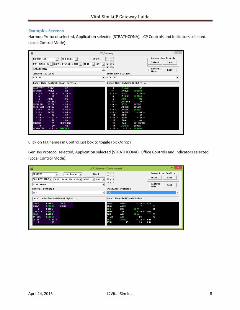
Examples Screens
Harmon Protocol selected, Application selected (STRATHCONA), LCP Controls and Indicators selected.
(Local Control Mode):
Click on tag names in Control List box to toggle (pick/drop)
Genisys Protocol selected, Application selected (STRATHCONA), Office Controls and Indicators selected.
(Local Control Mode):
Vital-Sim LCP Gateway Guide
April 24, 2015 ©Vital-Sim Inc. 9
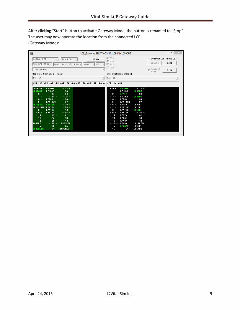
After clicking “Start” button to activate Gateway Mode, the button is renamed to “Stop”.
The user may now operate the location from the connected LCP.
(Gateway Mode):
Vital-Sim LCP Gateway Guide
April 24, 2015 ©Vital-Sim Inc. 10
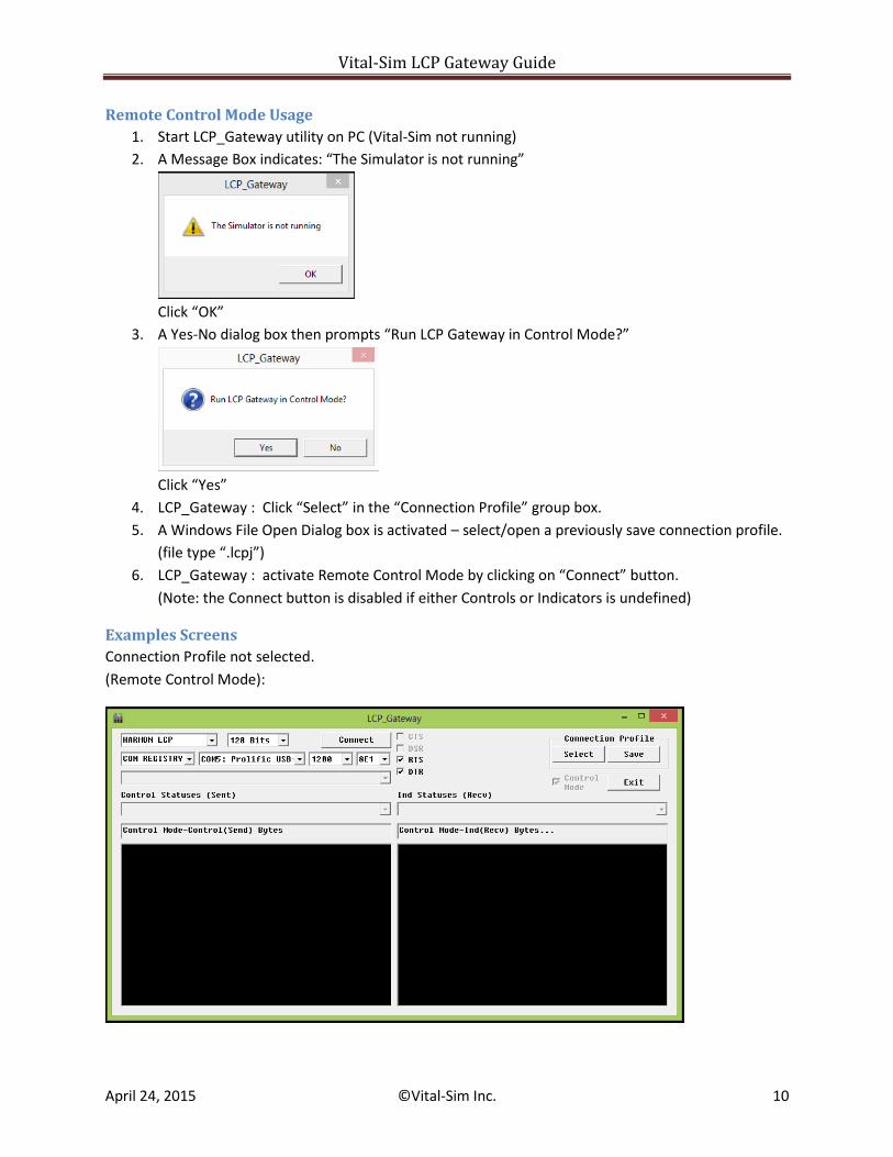
Remote Control Mode Usage
1. Start LCP_Gateway utility on PC (Vital-Sim not running)
2. A Message Box indicates: “The Simulator is not running”
Click “OK”
3. A Yes-No dialog box then prompts “Run LCP Gateway in Control Mode?”
Click “Yes”
4. LCP_Gateway : Click “Select” in the “Connection Profile” group box.
5. A Windows File Open Dialog box is activated – select/open a previously save connection profile.
(file type “.lcpj”)
6. LCP_Gateway : activate Remote Control Mode by clicking on “Connect” button.
(Note: the Connect button is disabled if either Controls or Indicators is undefined)
Examples Screens
Connection Profile not selected.
(Remote Control Mode):
Vital-Sim LCP Gateway Guide
April 24, 2015 ©Vital-Sim Inc. 11
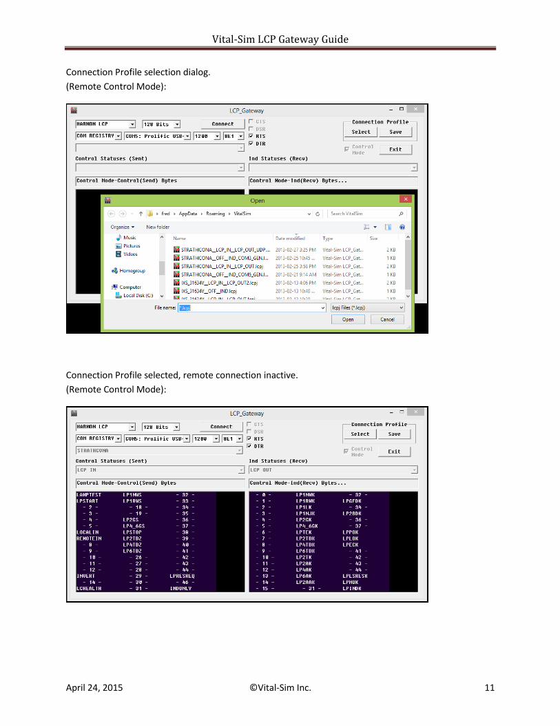
Connection Profile selection dialog.
(Remote Control Mode):
Connection Profile selected, remote connection inactive.
(Remote Control Mode):
Vital-Sim LCP Gateway Guide
April 24, 2015 ©Vital-Sim Inc. 12
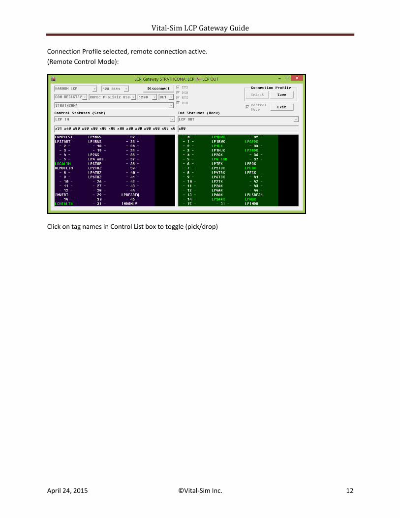
Connection Profile selected, remote connection active.
(Remote Control Mode):
Click on tag names in Control List box to toggle (pick/drop)
Vital-Sim LCP Gateway Guide
April 24, 2015 ©Vital-Sim Inc. 13
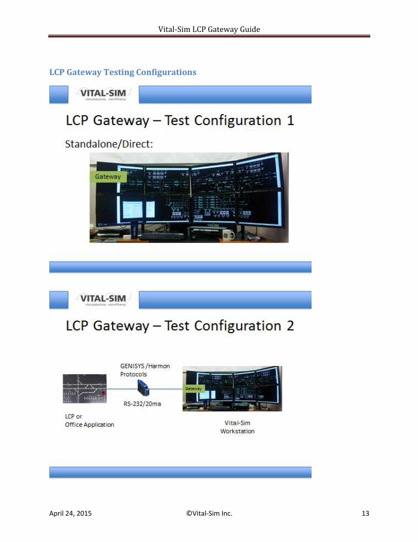
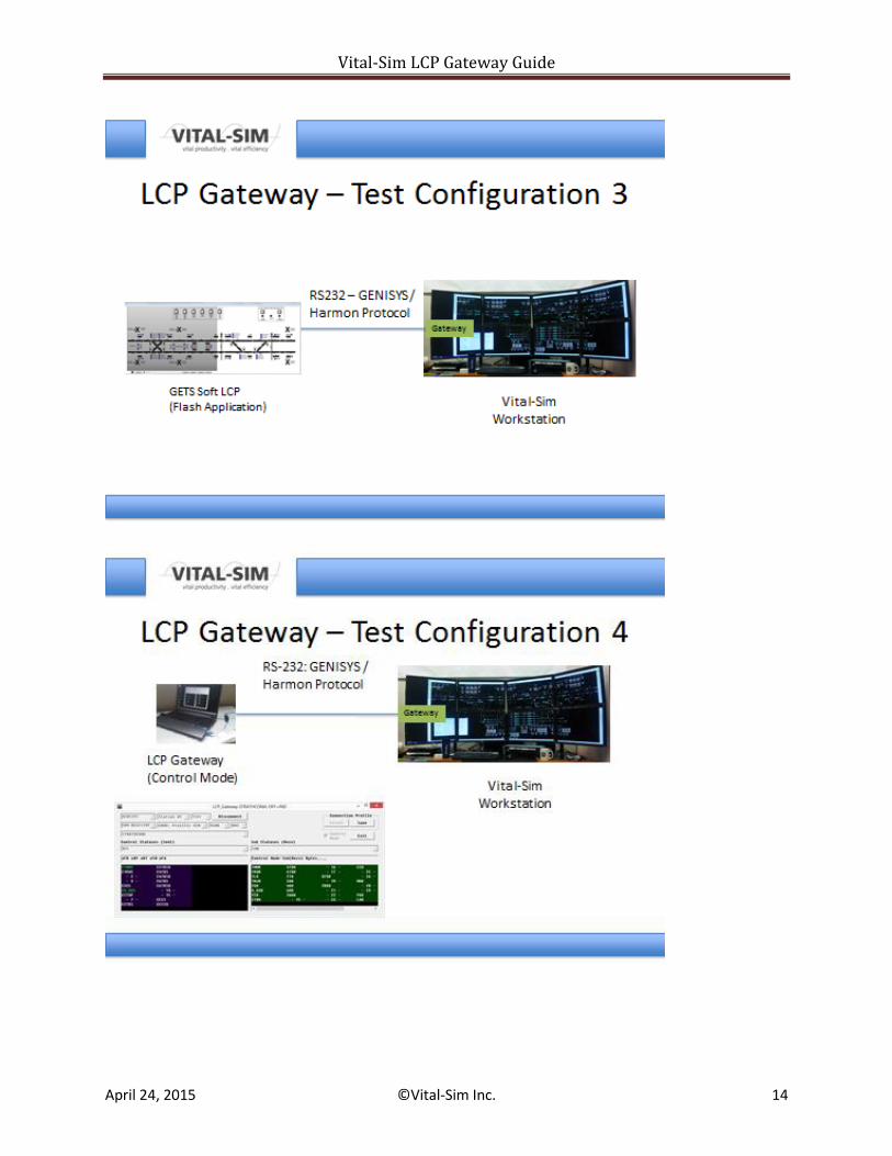
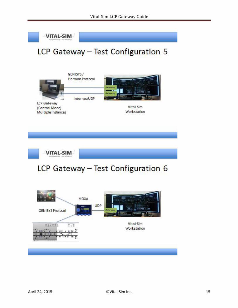
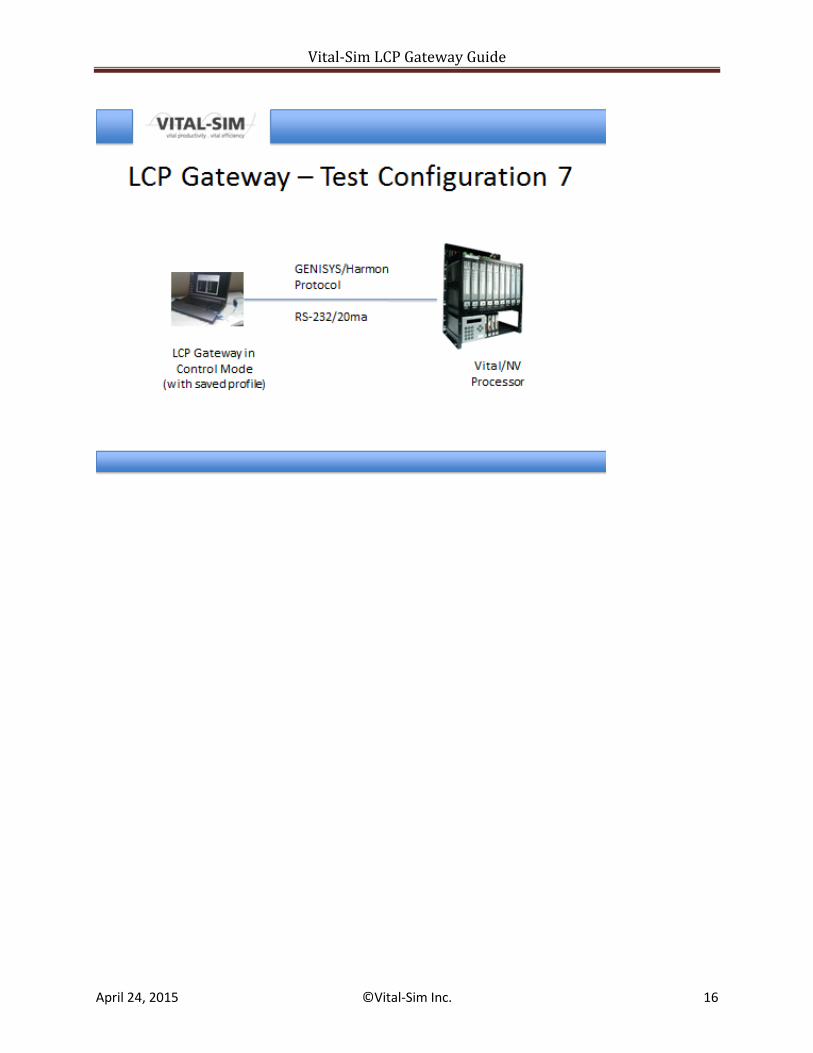
LCP Gateway Testing Configurations
Vital-Sim LCP Gateway Guide
April 24, 2015 ©Vital-Sim Inc. 14
Vital-Sim LCP Gateway Guide
April 24, 2015 ©Vital-Sim Inc. 15
Vital-Sim LCP Gateway Guide
April 24, 2015 ©Vital-Sim Inc. 16
Vital-Sim LCP Gateway Guide
April 24, 2015 ©Vital-Sim Inc. 17
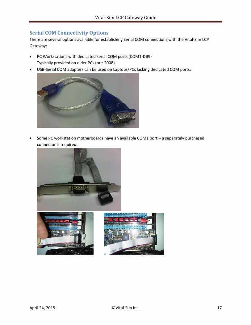
Serial COM Connectivity Options There are several options available for establishing Serial COM connections with the Vital-Sim LCP
Gateway:
PC Workstations with dedicated serial COM ports (COM1-DB9)
Typically provided on older PCs (pre-2008).
USB-Serial COM adapters can be used on Laptops/PCs lacking dedicated COM ports:
Some PC workstation motherboards have an available COM1 port – a separately purchased
connector is required:
Vital-Sim LCP Gateway Guide
April 24, 2015 ©Vital-Sim Inc. 18
Serial PCI Adapter Cards are available from several vendors:
(e.g., ST Lab 2-Port Serial PCI Adapter)
To connect to an LCP device with a 20ma current loop interface, an RS-232 to current loop adapter is
required.
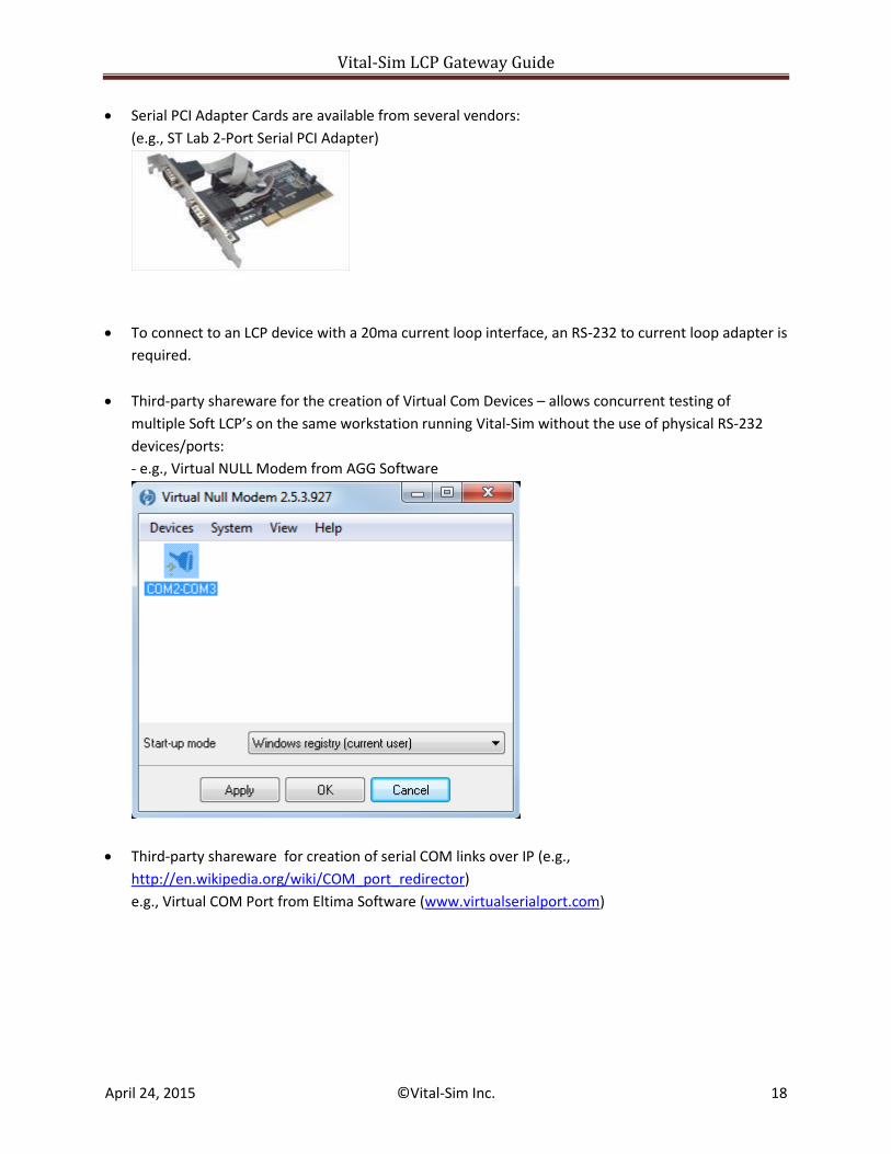
Third-party shareware for the creation of Virtual Com Devices – allows concurrent testing of
multiple Soft LCP’s on the same workstation running Vital-Sim without the use of physical RS-232
devices/ports:
- e.g., Virtual NULL Modem from AGG Software
Third-party shareware for creation of serial COM links over IP (e.g.,
http://en.wikipedia.org/wiki/COM_port_redirector)
e.g., Virtual COM Port from Eltima Software (www.virtualserialport.com)
Vital-Sim LCP Gateway Guide
April 24, 2015 ©Vital-Sim Inc. 19
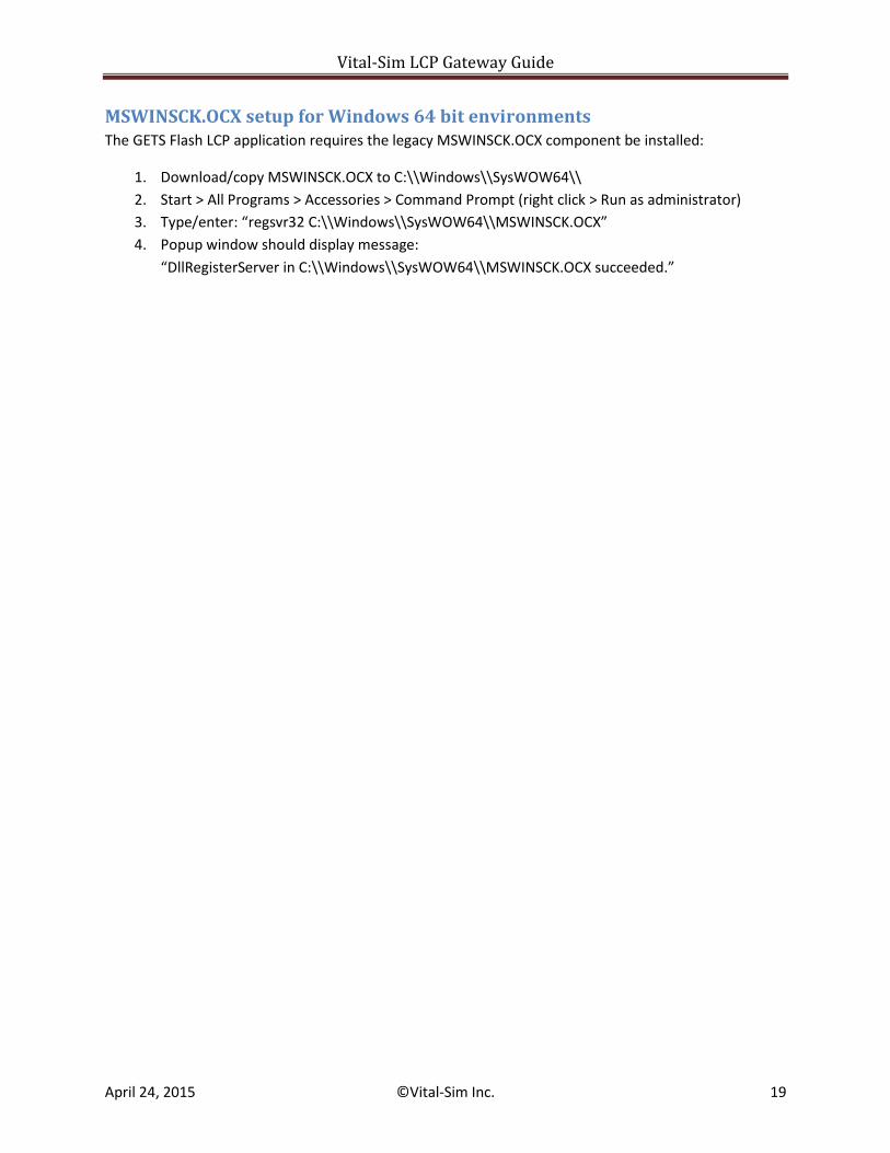
MSWINSCK.OCX setup for Windows 64 bit environments The GETS Flash LCP application requires the legacy MSWINSCK.OCX component be installed:
1. Download/copy MSWINSCK.OCX to C:\\Windows\\SysWOW64\\
2. Start > All Programs > Accessories > Command Prompt (right click > Run as administrator)
3. Type/enter: “regsvr32 C:\\Windows\\SysWOW64\\MSWINSCK.OCX”
4. Popup window should display message:
“DllRegisterServer in C:\\Windows\\SysWOW64\\MSWINSCK.OCX succeeded.”