Embed Size (px)
Citation preview
1/7
Mounting Options for VisuNet IND 900 Series
model number for Pedestal for VisuNet IND
Description
VESA CABLE FEEDTHROUGH
Adaptor plate with 2 x M20 Cable glands for installing cables through pedestal
Pedestal1-150-1V-NP-G-T-304 (340° turnable) Pedestal1-150-1V-NP-G-F-304 (fix mounted)
Pedestal inclination of monitor 10°,
PEDSTAL1-130-3V-NP-G-T-304 (340° turnable) PEDESTAL1-130-3V-NP-G-F-304 (fix mounted)
Pedestal, inclination of monitor 30° (Optional with adjustable keyboard at monitor housing)
PEDESTAL1-56-3V-NP-G-T-304 (340° turnable)
Pedestal for table Pedestal, inclination of monitor 30° With mounting plate 350 x 350 mm
WALL-ARM1-55-1V-NT-G-T-304 (350° turnable) WALL-ARM1-55-1V-NT-G-F-304 (fix mounted)
Wall arm inclination of monitor 10°
WALL-BRACKET1-0-0V-G-304
Wall mount bracket
2/7
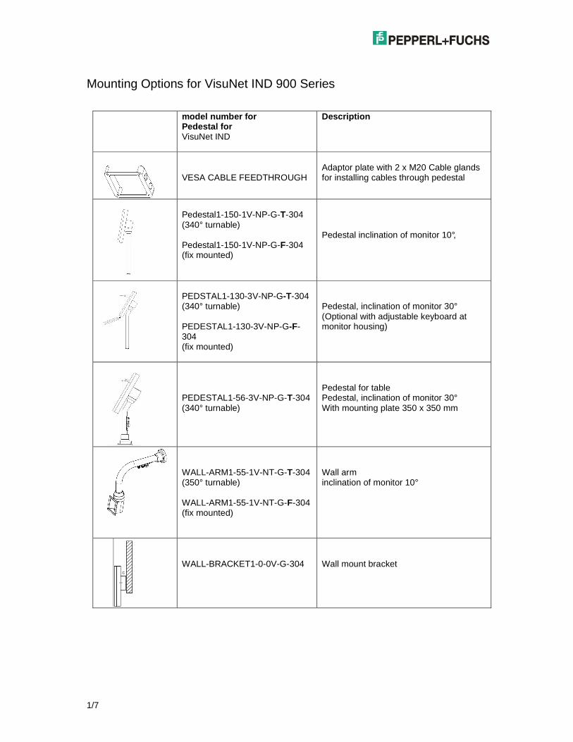
Dimensions
1500
PEDESTAL1-150-1V-NP-G-x-304
PEDESTAL1-130-3V-NP-G-x-304
PEDESTAL1-56-3V-NP-G-T-304
WALL-ARM1-55-1V-NT-G-x-304
WALL-BRACKET1-0-0V-G-304
3/7
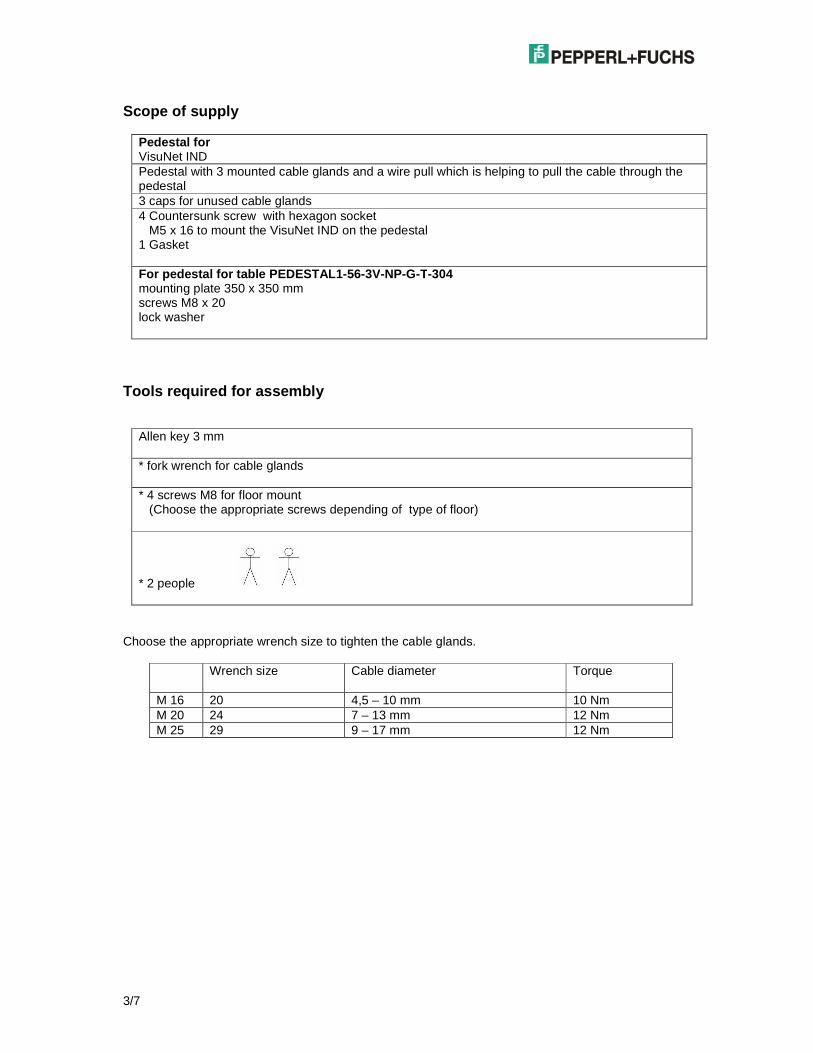
Scope of supply
Pedestal for VisuNet IND Pedestal with 3 mounted cable glands and a wire pull which is helping to pull the cable through the pedestal 3 caps for unused cable glands 4 Countersunk screw with hexagon socket M5 x 16 to mount the VisuNet IND on the pedestal 1 Gasket For pedestal for table PEDESTAL1-56-3V-NP-G-T-304 mounting plate 350 x 350 mm screws M8 x 20 lock washer
Tools required for assembly
Allen key 3 mm * fork wrench for cable glands * 4 screws M8 for floor mount (Choose the appropriate screws depending of type of floor)
* 2 people
Choose the appropriate wrench size to tighten the cable glands.
Wrench size Cable diameter
Torque
M 16 20 4,5 – 10 mm 10 Nm M 20 24 7 – 13 mm 12 Nm M 25 29 9 – 17 mm 12 Nm
4/7
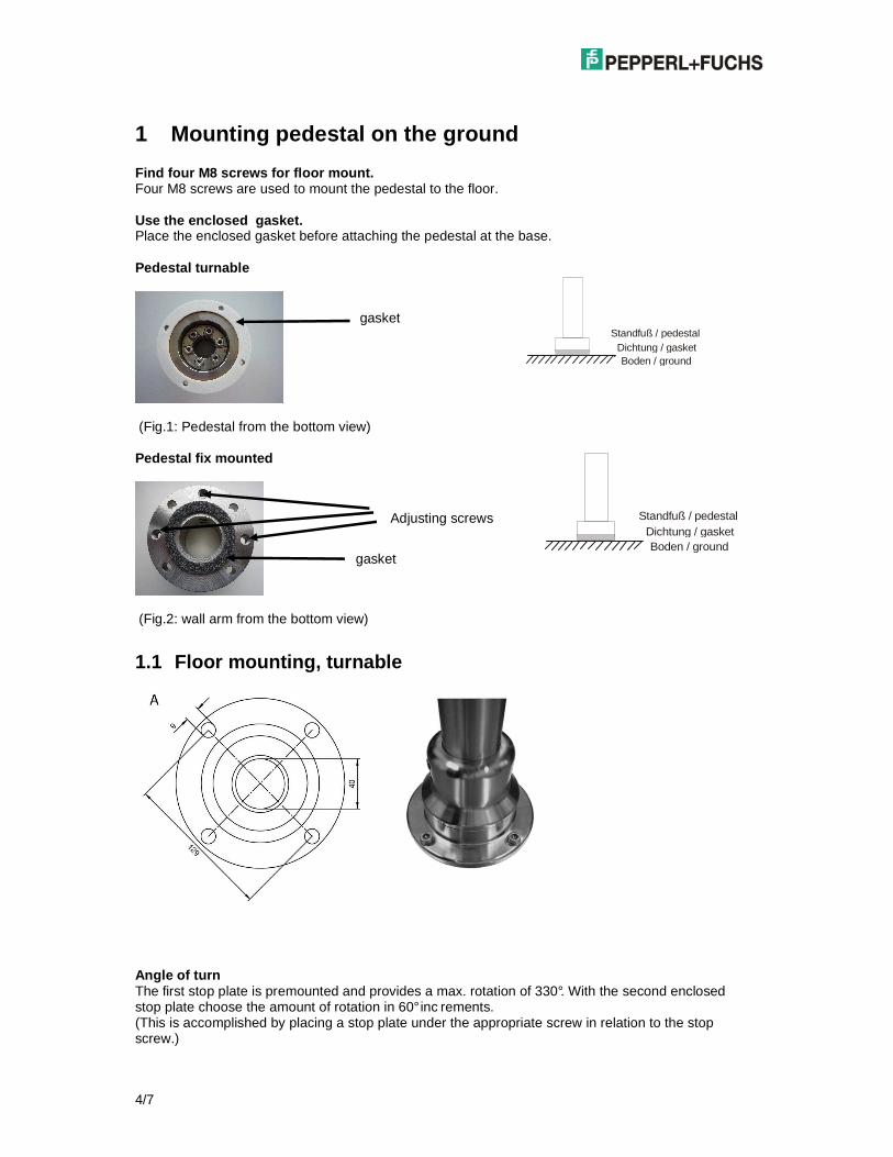
1 Mounting pedestal on the ground Find four M8 screws for floor mount. Four M8 screws are used to mount the pedestal to the floor. Use the enclosed gasket. Place the enclosed gasket before attaching the pedestal at the base. Pedestal turnable
(Fig.1: Pedestal from the bottom view) Pedestal fix mounted
(Fig.2: wall arm from the bottom view)
1.1 Floor mounting, turnable
Angle of turn The first stop plate is premounted and provides a max. rotation of 330°. With the second enclosed stop plate choose the amount of rotation in 60° inc rements. (This is accomplished by placing a stop plate under the appropriate screw in relation to the stop screw.)
gasket
Boden / groundDichtung / gasket
Standfuß / pedestal
gasket
Adjusting screws
Boden / groundDichtung / gasket
Standfuß / pedestal
5/7
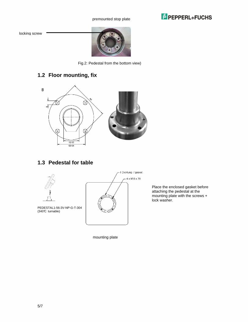
Fig.2: Pedestal from the bottom view)
1.2 Floor mounting, fix
1.3 Pedestal for table
PEDESTAL1-56-3V-NP-G-T-304 (340°C turnable) mounting plate
premounted stop plate
locking screw
Place the enclosed gasket before attaching the pedestal at the mounting plate with the screws + lock washer.
6/7
2 Connect all cables VisuNet IND This requires 2 people. Connect correctly all cables at the VisuNet IND. (See VisuNet IND manual Interfaces and connections) One person holds the VisuNet IND while the other person connects the cables.
3 Mounting the VisuNet IND on pedestal This requires 2 people. One person holds the VisuNet IND the other person attaches the cover. Attach the VisuNet on the pedestal as follows:
VisuNet IND Torque 5 -6 Nm 4 Countersunk screw with hexagon socket M5 x 16 Allen Key 3 mm
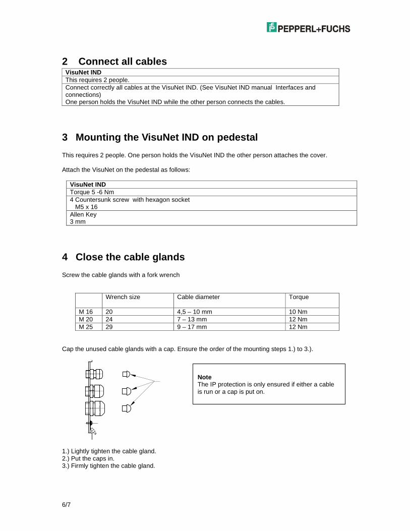
4 Close the cable glands Screw the cable glands with a fork wrench
Wrench size Cable diameter
Torque
M 16 20 4,5 – 10 mm 10 Nm M 20 24 7 – 13 mm 12 Nm M 25 29 9 – 17 mm 12 Nm
Cap the unused cable glands with a cap. Ensure the order of the mounting steps 1.) to 3.).
1.) Lightly tighten the cable gland. 2.) Put the caps in. 3.) Firmly tighten the cable gland.
Note The IP protection is only ensured if either a cable is run or a cap is put on.
7/7
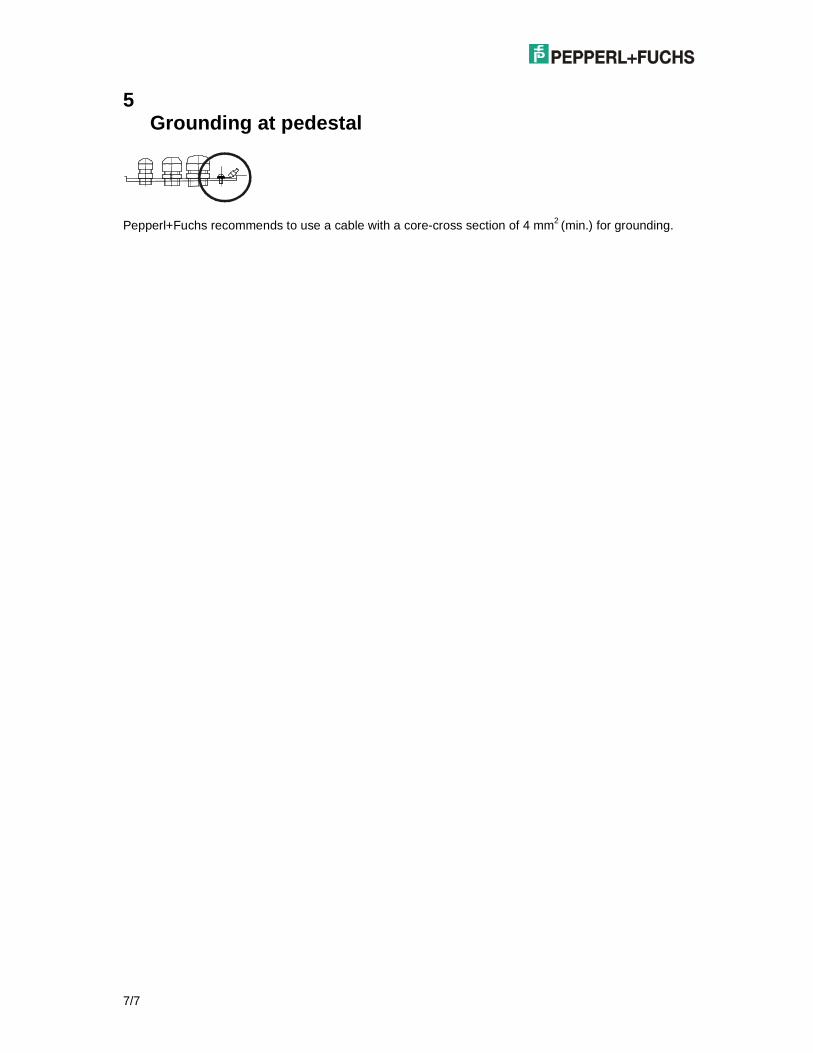
5 Grounding at pedestal
Pepperl+Fuchs recommends to use a cable with a core-cross section of 4 mm2 (min.) for grounding.