Embed Size (px)
Citation preview

8/16/2019 Visual Mill Getting Started Guide
http://slidepdf.com/reader/full/visual-mill-getting-started-guide 1/411

8/16/2019 Visual Mill Getting Started Guide
http://slidepdf.com/reader/full/visual-mill-getting-started-guide 2/411
VisualMILL 6.0 Getting Started Guide
Copyright 1998-2007, MecSoft Corporation, www.mecsoft.com
Create Tools ...........................................................................................161
Create Machining Operations .....................................................................165
V-Carving Roughing .................................................................................165
V-Carving ...............................................................................................174
Post Processing .......................................................................................180
Tutorial 6: Chamfering.................................................................................181
Introduction............................................................................................182 Preparing the part for Machining ................................................................182
Create Tools ...........................................................................................185
Create Machining Operations .....................................................................187
Chamfering.............................................................................................187
Post Processing .......................................................................................196
Tutorial 7: 3 Axis Milling...............................................................................198
Introduction............................................................................................199
Preparing the part for Machining ................................................................199
Create Tools ...........................................................................................209
Create Machining Operations .....................................................................212
3 axis Horizontal Roughing........................................................................212
3 axis Parallel Finishing ............................................................................220
3 axis Horizontal Finishing.........................................................................223
Post Processing .......................................................................................229
Tutorial 8: Profiling with Bridges (Tabs)..........................................................230
Introduction............................................................................................231
Preparing the part for Machining ................................................................231
Create Tools ...........................................................................................244
Create Machining Operations .....................................................................246
2 ½ Axis Profiling.....................................................................................246
Post Processing .......................................................................................260
Tutorial 9: Hole Making................................................................................261
Introduction............................................................................................262
Preparing the part for Machining ................................................................262
Create Tools ...........................................................................................271 Create/Extract Regions.............................................................................273
Create Machining Operations .....................................................................275
Hole Machining........................................................................................275
Creating the Drill operation for the 0.25” Holes ............................................286
Post Processing .......................................................................................288
Tutorial 10: Machining a Ring .......................................................................289
Introduction............................................................................................290
Preparing the part for Machining ................................................................290
Create Tools ...........................................................................................303
Create Machining Operations .....................................................................305
4 axis Roughing.......................................................................................306
4 axis Finishing .......................................................................................313
Post Processing .......................................................................................317
Tutorial 11: Engraving on a Cylinder..............................................................318
Introduction............................................................................................319
Preparing the part for Machining ................................................................319
Create Tools ...........................................................................................330
Create Machining Operations .....................................................................333
4 Axis Engraving......................................................................................333
Post Processing .......................................................................................342
Tutorial 12: Machining a Ring .......................................................................344

8/16/2019 Visual Mill Getting Started Guide
http://slidepdf.com/reader/full/visual-mill-getting-started-guide 3/411
VisualMILL 6.0 Getting Started Guide
Copyright 1998-2007, MecSoft Corporation, www.mecsoft.com
Introduction............................................................................................345
Preparing the part for Machining ................................................................345
Create Tools ...........................................................................................357
Create Machining Operations .....................................................................360
4th axis Roughing.....................................................................................361
4th Axis Roughing operation #2..................................................................368
4th
axis Finishing......................................................................................373 Post Processing .......................................................................................377
Tutorial 13: Pocketing and Drilling on a Ring...................................................378
Introduction............................................................................................379
Preparing the part for Machining ................................................................379
Create Tools ...........................................................................................390
Create Machining Operations .....................................................................393
4 Axis Drilling..........................................................................................394
4 axis Pocketing ......................................................................................403
Post Processing .......................................................................................411

8/16/2019 Visual Mill Getting Started Guide
http://slidepdf.com/reader/full/visual-mill-getting-started-guide 4/411
VisualMILL 6.0 Getting Started Guide
Copyright 1998-2007, MecSoft Corporation, www.mecsoft.com
Welcome to VisualMILL Getting Started Guide
Welcome to VisualMILL and thank you for choosing one of most powerful and easy to
use complete CAD/CAM packages on the market today.
VisualMILL is a unique CAM product plug-in that runs inside of VisualCAM. Plug-inscan be considered as independent applications that can be loaded and unloaded on
demand from the host program, which in this case is VisualCAM. This fully
integrated VisualMILL plug-in seamlessly integrates VisualCAM’s CAD functionalitywith toolpath generation and cutting simulation/verification, in one package that is
both easy and fun to use.
You can work with the native VisualCAM design data as well as use any of the datatypes that can be imported into VisualCAM such as solids, surfaces and meshes.
Then you can use VisualMILL with its wide selection of tools and toolpath strategiesto create machining operations and associated toolpaths. These toolpaths can then
be simulated and verified, and finally post-processed to the controller of your choice.
About this Guide
Welcome to the VisualMILL getting started guide. This file contains various tutorials
to help you get started with learning VisualMILL. Each tutorial lesson has twoassociated VisualCAM files that you can find located in the Tutorials folder under the
installation folder of VisualMILL. The first file is a completed file that contains all of
the completed toolpaths and machining operations and represents the file that youshould end up with after working through the tutorial. The other file is a starter file
that contains only the geometry. Use the completed file as a reference. Copy thestarter file and use this file to begin each tutorial.
Good luck and have fun!
Where to go for more help
Apart from the on-line help system you can download tutorials and projects from
MecSoft Corporation's web site at www.mecsoft.com. This will help you get startedwith using VisualMILL.
If you need additional help, or if you have any questions regarding VisualMILL, youmay contact us via e-mail at [email protected]
MecSoft offers Online training as well as personalized full day training sessions.
Please look up our website or email us at [email protected] for further details
Please do continue to visit our home page to learn about the latest updates toVisualMILL and any other help material.

8/16/2019 Visual Mill Getting Started Guide
http://slidepdf.com/reader/full/visual-mill-getting-started-guide 5/411
VisualMILL 6.0 Getting Started Guide
Copyright 1998-2007, MecSoft Corporation, www.mecsoft.com
Tutorial 1: Machining a Gasket
8/16/2019 Visual Mill Getting Started Guide
http://slidepdf.com/reader/full/visual-mill-getting-started-guide 6/411
VisualMILL 6.0 Getting Started Guide
Copyright 1998-2007, MecSoft Corporation, www.mecsoft.com
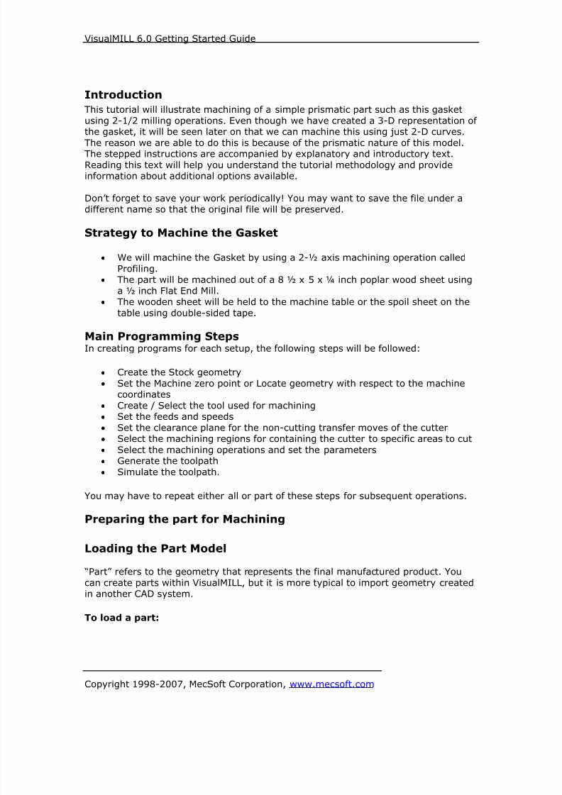
Introduction
This tutorial will illustrate machining of a simple prismatic part such as this gasket
using 2-1/2 milling operations. Even though we have created a 3-D representation ofthe gasket, it will be seen later on that we can machine this using just 2-D curves.
The reason we are able to do this is because of the prismatic nature of this model.The stepped instructions are accompanied by explanatory and introductory text.
Reading this text will help you understand the tutorial methodology and provideinformation about additional options available.
Don’t forget to save your work periodically! You may want to save the file under adifferent name so that the original file will be preserved.
Strategy to Machine the Gasket
• We will machine the Gasket by using a 2-½ axis machining operation called
Profiling.• The part will be machined out of a 8 ½ x 5 x ¼ inch poplar wood sheet using
a ½ inch Flat End Mill.• The wooden sheet will be held to the machine table or the spoil sheet on the
table using double-sided tape.
Main Programming StepsIn creating programs for each setup, the following steps will be followed:
• Create the Stock geometry
• Set the Machine zero point or Locate geometry with respect to the machinecoordinates
• Create / Select the tool used for machining
• Set the feeds and speeds• Set the clearance plane for the non-cutting transfer moves of the cutter
• Select the machining regions for containing the cutter to specific areas to cut
• Select the machining operations and set the parameters
• Generate the toolpath
• Simulate the toolpath.
You may have to repeat either all or part of these steps for subsequent operations.
Preparing the part for Machining
Loading the Part Model
“Part” refers to the geometry that represents the final manufactured product. You
can create parts within VisualMILL, but it is more typical to import geometry createdin another CAD system.
To load a part:

8/16/2019 Visual Mill Getting Started Guide
http://slidepdf.com/reader/full/visual-mill-getting-started-guide 7/411
VisualMILL 6.0 Getting Started Guide
Copyright 1998-2007, MecSoft Corporation, www.mecsoft.com
1. Select File / Open from the Menu, or click the Open icon from the Standard
bar.
2. From the Open dialog box, select the Gasket.vcp file from the Tutorials folderin the VisualMILL 6.0 installation folder. (C:\Program Files\MecSoft
Corporation\VisualCAM 1.0\Plug-ins\VisualMILL 6.0\Tutorials)
The imported part appears as shown below
Note: You can import solid models, Stereo-Lithography (both ASCII and binary)
format files. Surfaces can be imported from IGES, STEP or Rhino 3DM. Faceted
(triangulated) models can be imported from VRML, Raw Triangle, DXF / DWG facetdata, or Rhino Mesh. Non-faceted geometry, once imported, is immediately
converted and stored as triangulated data. Imported geometry is stored internally asa VisualCAM part file. This allows for much faster part loading time.

8/16/2019 Visual Mill Getting Started Guide
http://slidepdf.com/reader/full/visual-mill-getting-started-guide 8/411
VisualMILL 6.0 Getting Started Guide
Copyright 1998-2007, MecSoft Corporation, www.mecsoft.com
Setup Tab
1. Go to the VisualMILL- MOps browser and click on the Setup tab
2. Select Machine Setup from the setup tab.
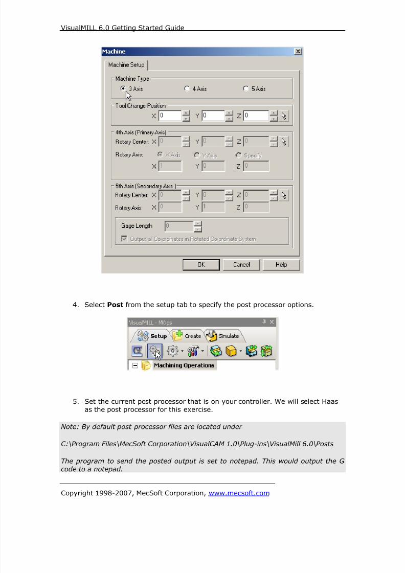
3. Set the Machine type to 3 axis

8/16/2019 Visual Mill Getting Started Guide
http://slidepdf.com/reader/full/visual-mill-getting-started-guide 9/411
VisualMILL 6.0 Getting Started Guide
Copyright 1998-2007, MecSoft Corporation, www.mecsoft.com
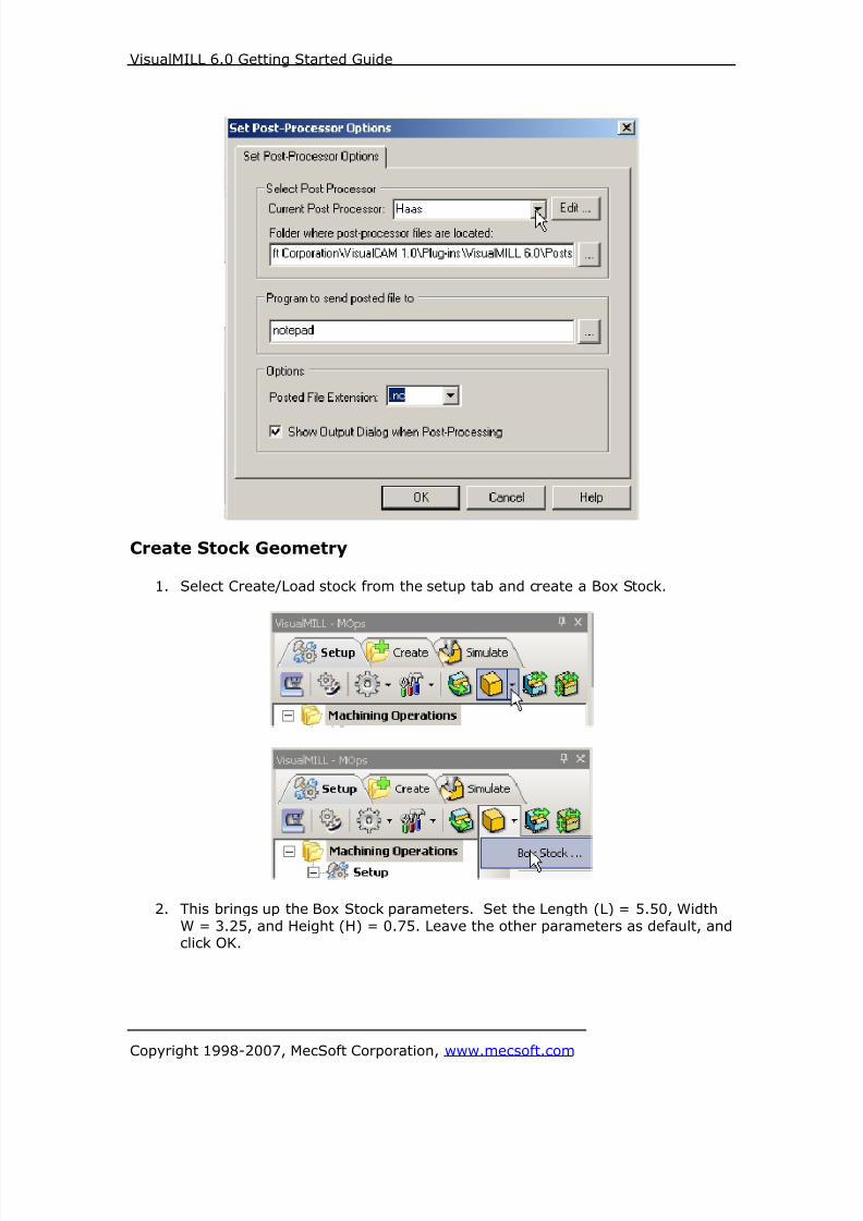
4. Select Post from the setup tab to specify the post processor options
5. Set the current post processor that is on your controller. We will select
Haas as the post processor for this exercise. Set the posted file extension
type to .nc
Note: By default post processor files are located under
C:\Program Files\MecSoft Corporation\VisualCAM 1.0\Plug-ins\VisualMill 6.0\Posts

8/16/2019 Visual Mill Getting Started Guide
http://slidepdf.com/reader/full/visual-mill-getting-started-guide 10/411
VisualMILL 6.0 Getting Started Guide
Copyright 1998-2007, MecSoft Corporation, www.mecsoft.com
The program to send the posted output is set to notepad. This would output the G
code to a notepad.
Create Stock Geometry
1. Select Create/Load stock from the setup tab and create a Box Stock
2. This brings up the Box Stock parameters. Set the Length (L) = 8.50, Width W
= 5.00 and Height (H) = 0.125. Leave the other parameters as default and
Click OK.

8/16/2019 Visual Mill Getting Started Guide
http://slidepdf.com/reader/full/visual-mill-getting-started-guide 11/411
VisualMILL 6.0 Getting Started Guide
Copyright 1998-2007, MecSoft Corporation, www.mecsoft.com
3. The stock geometry is now created, and a semi-transparent stock box isdisplayed on top of the part geometry.
4. The setup tab now displays the following information: Machine Type, Post
Processor, and Stock type as show below.
8/16/2019 Visual Mill Getting Started Guide
http://slidepdf.com/reader/full/visual-mill-getting-started-guide 12/411
VisualMILL 6.0 Getting Started Guide
Copyright 1998-2007, MecSoft Corporation, www.mecsoft.com
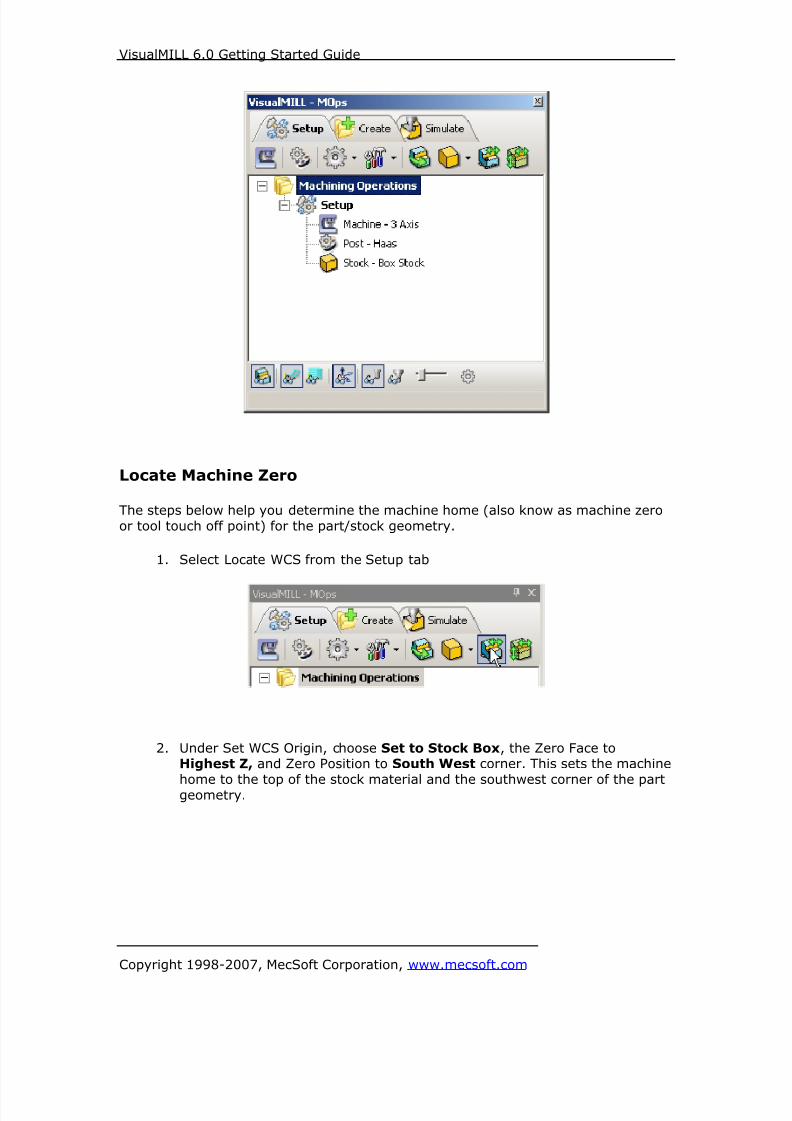
Locate Machine Zero
The steps below help you determine the machine home (also know as machine zero
or tool touch off point) for the part/stock geometry.
1. Select Locate WCS from the Setup tab
2. Under Set WCS Origin, choose Set to Stock Box, the Zero Face toHighest Z, and Zero Position to South West corner. This sets the machine
home to the top of the stock material and the southwest corner of the partgeometry.
8/16/2019 Visual Mill Getting Started Guide
http://slidepdf.com/reader/full/visual-mill-getting-started-guide 13/411
VisualMILL 6.0 Getting Started Guide
Copyright 1998-2007, MecSoft Corporation, www.mecsoft.com
Note: You can change the stock model transparency under standard mode by
selecting Simulation Preferences that is located at the bottom of the MOps browser.

8/16/2019 Visual Mill Getting Started Guide
http://slidepdf.com/reader/full/visual-mill-getting-started-guide 14/411
VisualMILL 6.0 Getting Started Guide
Copyright 1998-2007, MecSoft Corporation, www.mecsoft.com
Align Part and Stock
In this process, we can align the part and the stock geometry. As we have set the
Machine zero to the Stock Box, we will now move the part relative to the stock.
1. Select Align Part and Stock from the Setup tab
2. Set to Object to Move as Move Part, Z alignment to Top and XY alignmentto Center
8/16/2019 Visual Mill Getting Started Guide
http://slidepdf.com/reader/full/visual-mill-getting-started-guide 15/411
VisualMILL 6.0 Getting Started Guide
Copyright 1998-2007, MecSoft Corporation, www.mecsoft.com
The part geometry is aligned to the center of stock in XY and top in Z. Click Save
to save the work and specify a file name as Gasket-Rev1. The file is now saved
with extension vcp. (VisualCAM Part File)
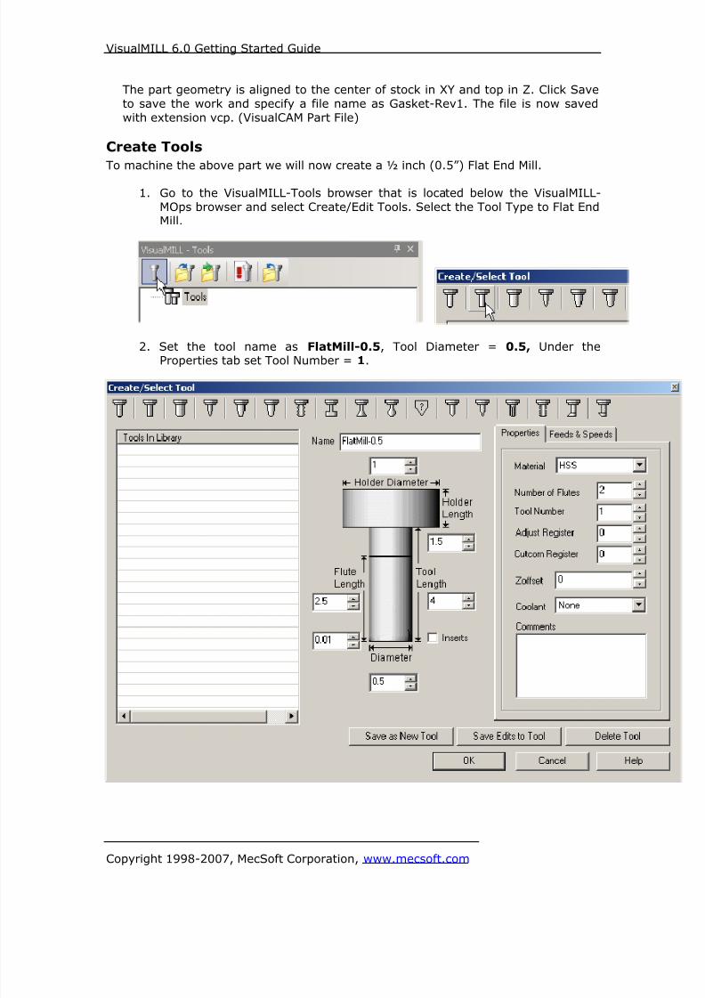
Create Tools
To machine the above part we will now create a ½ inch (0.5”) Flat End Mill.
1. Go to the VisualMILL-Tools browser that is located below the VisualMILL-
MOps browser and select Create/Edit Tools. Select the Tool Type to Flat EndMill.
2. Set the tool name as FlatMill-0.5, Tool Diameter = 0.5, Under theProperties tab set Tool Number = 1.

8/16/2019 Visual Mill Getting Started Guide
http://slidepdf.com/reader/full/visual-mill-getting-started-guide 16/411
VisualMILL 6.0 Getting Started Guide
Copyright 1998-2007, MecSoft Corporation, www.mecsoft.com
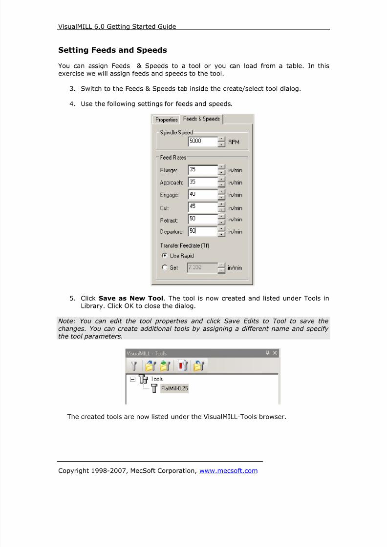
Setting Feeds and Speeds
You can assign Feeds & Speeds to a tool or you can load from a table. In this
exercise, we will assign feeds and speeds to the tool.
3. Switch to the Feeds & Speeds tab inside the create/select tool dialog.
4. Use the following settings for feeds and speeds.
5. Click Save as New Tool. The tool is now created and listed under Tools inLibrary. Click OK to close the dialog.
Note: You can edit the tool properties and click Save Edits to Tool to save the
changes. You can create additional tools by assigning a different name and specifythe tool parameters.
The created tools are now listed under the VisualMILL-Tools browser.
8/16/2019 Visual Mill Getting Started Guide
http://slidepdf.com/reader/full/visual-mill-getting-started-guide 17/411
VisualMILL 6.0 Getting Started Guide
Copyright 1998-2007, MecSoft Corporation, www.mecsoft.com
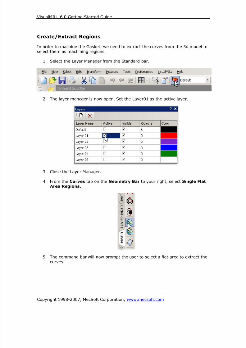
Create/Extract Regions
In order to machine the Gasket, we need to extract the curves from the 3d model to
select them as machining regions.
1. Select the Layer Manager from the Standard bar.
2. The layer manager is now open. Set the Layer01 as the active layer.
3. Close the Layer Manager.
4. From the Curves tab on the Geometry Bar to your right, select Single FlatArea Regions.
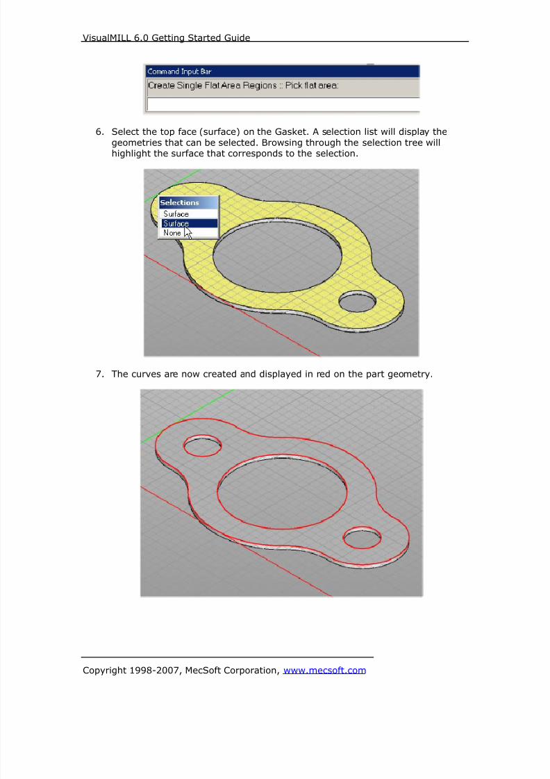
5. The command bar will now prompt the user to select a flat area to extract the
curves.
8/16/2019 Visual Mill Getting Started Guide
http://slidepdf.com/reader/full/visual-mill-getting-started-guide 18/411
VisualMILL 6.0 Getting Started Guide
Copyright 1998-2007, MecSoft Corporation, www.mecsoft.com
6. Select the top face (surface) on the Gasket. A selection list will display thegeometries that can be selected. Browsing through the selection tree willhighlight the surface that corresponds to the selection.
7. The curves are now created and displayed in red on the part geometry.

8/16/2019 Visual Mill Getting Started Guide
http://slidepdf.com/reader/full/visual-mill-getting-started-guide 19/411
VisualMILL 6.0 Getting Started Guide
Copyright 1998-2007, MecSoft Corporation, www.mecsoft.com
Note: You can toggle the stock model display by selecting Stock Visibility that is
located at the bottom of the VisualMill-MOps Browser
Create Machining Operations
In this process we will create a 2.5 axis profiling operation.
1. Switch to the Create Operations tab in VisualMILL-Mops browser.
2 ½ Axis Profiling
1. Select 2.5 Axis Mill and choose Profiling
This brings up the 2 ½ Axis Profiling Operations dialog. We will go over thesteps for creating the profile operations for the inner features of the Gasket.

8/16/2019 Visual Mill Getting Started Guide
http://slidepdf.com/reader/full/visual-mill-getting-started-guide 20/411
VisualMILL 6.0 Getting Started Guide
Copyright 1998-2007, MecSoft Corporation, www.mecsoft.com
Select Machining Features/Regions2. Go to the Machining Features/ Regions tab and click Select Curves as
Regions
3. Now select the 3 inner circles by using the left mouse click starting from leftto right.

8/16/2019 Visual Mill Getting Started Guide
http://slidepdf.com/reader/full/visual-mill-getting-started-guide 21/411
VisualMILL 6.0 Getting Started Guide
Copyright 1998-2007, MecSoft Corporation, www.mecsoft.com
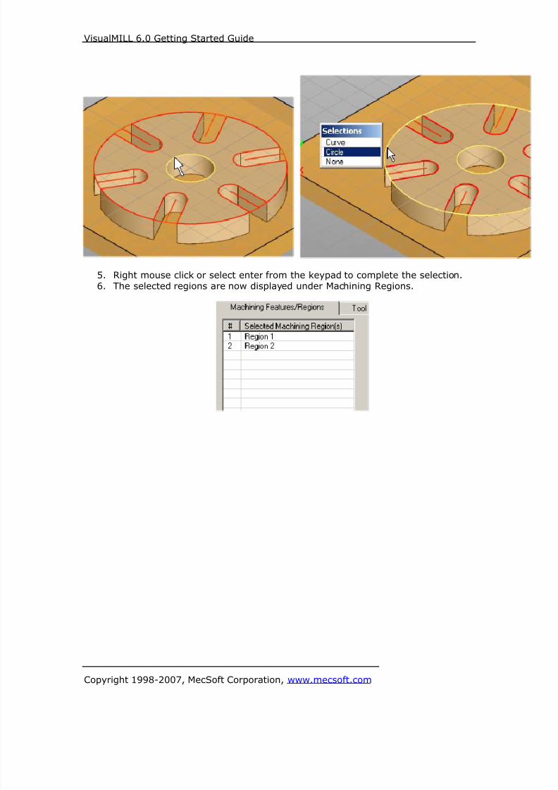
4. Right mouse click or select enter from the keypad to complete the
selection.5. The selected regions are now displayed under Machining Regions

8/16/2019 Visual Mill Getting Started Guide
http://slidepdf.com/reader/full/visual-mill-getting-started-guide 22/411
VisualMILL 6.0 Getting Started Guide
Copyright 1998-2007, MecSoft Corporation, www.mecsoft.com
Selecting the Tool
6. Switch to the Tools tab inside the 2 ½ Axis Profiling operation.
7. Select the FlatMill-0.5. The 0.5” Flat End mill is now selected as the activetool and the Tool parameters are displayed to the right of the Tools window.

8/16/2019 Visual Mill Getting Started Guide
http://slidepdf.com/reader/full/visual-mill-getting-started-guide 23/411
VisualMILL 6.0 Getting Started Guide
Copyright 1998-2007, MecSoft Corporation, www.mecsoft.com
Set Feeds and Speeds8. Click on the Feeds and Speeds tab.
9. Select Load From Tool. VisualMILL will now get the feeds and speeds
information that was set when the tool was defined.

8/16/2019 Visual Mill Getting Started Guide
http://slidepdf.com/reader/full/visual-mill-getting-started-guide 24/411
VisualMILL 6.0 Getting Started Guide
Copyright 1998-2007, MecSoft Corporation, www.mecsoft.com
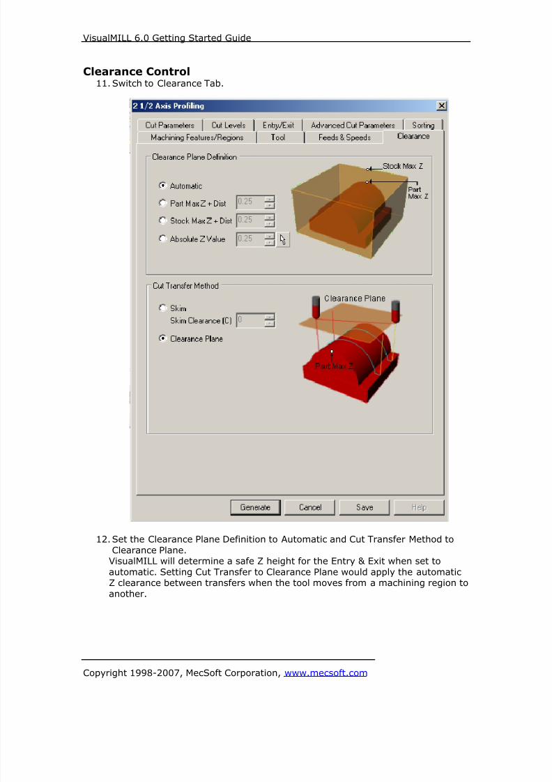
Clearance Control10. Switch to Clearance Tab.
11. Set the Clearance Plane Definition to Automatic and Cut Transfer Method to
Clearance Plane.VisualMILL will determine a safe Z height for the Entry & Exit when set to
automatic. Setting Cut Transfer to Clearance Plane would apply the automaticZ clearance between transfers when the tool moves from a machining region to
another.
8/16/2019 Visual Mill Getting Started Guide
http://slidepdf.com/reader/full/visual-mill-getting-started-guide 25/411
VisualMILL 6.0 Getting Started Guide
Copyright 1998-2007, MecSoft Corporation, www.mecsoft.com
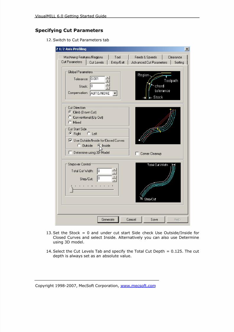
Specifying Cut Parameters
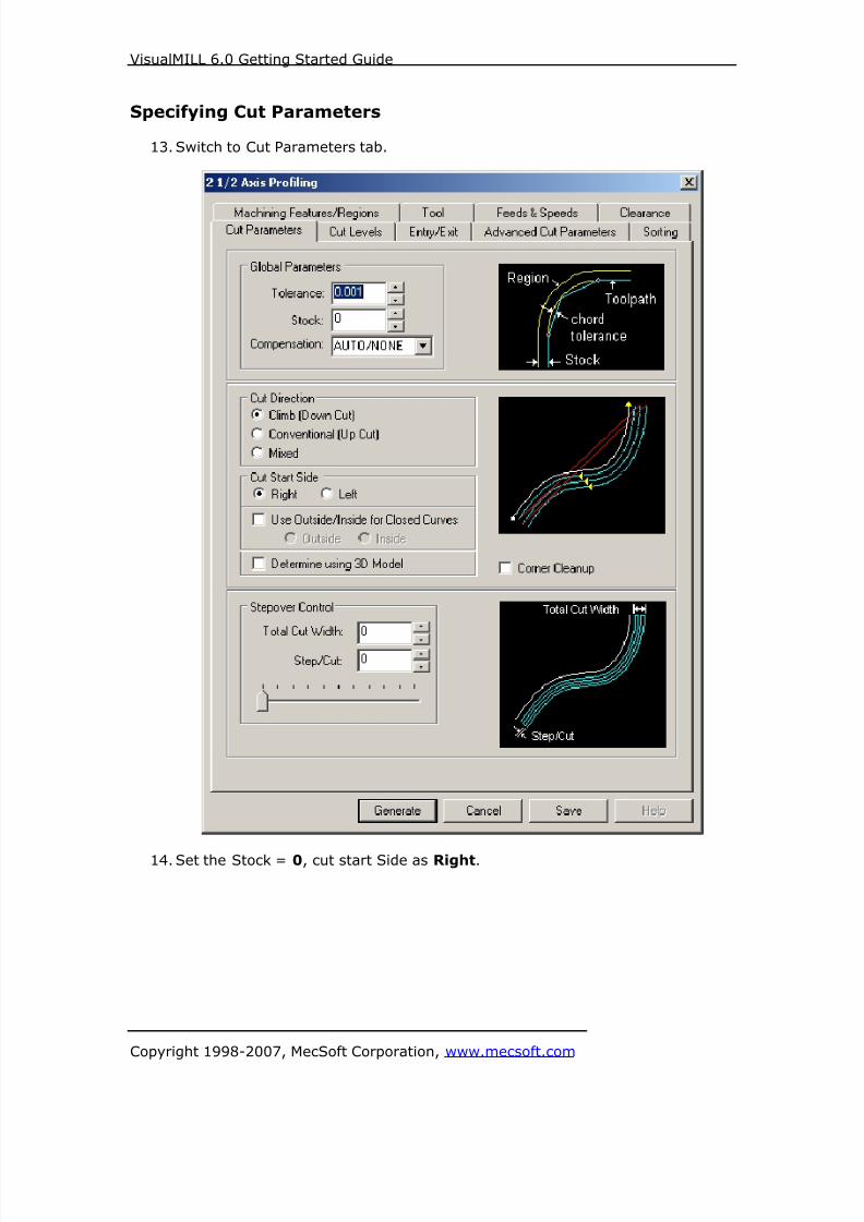
12. Switch to Cut Parameters tab
13. Set the Stock = 0 and under cut start Side check Use Outside/Inside forClosed Curves and select Inside. Alternatively you can also use Determineusing 3D model.
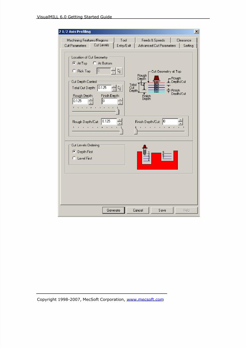
14. Select the Cut Levels Tab and specify the Total Cut Depth = 0.125. The cut
depth is always set as an absolute value.
8/16/2019 Visual Mill Getting Started Guide
http://slidepdf.com/reader/full/visual-mill-getting-started-guide 26/411
VisualMILL 6.0 Getting Started Guide
Copyright 1998-2007, MecSoft Corporation, www.mecsoft.com

8/16/2019 Visual Mill Getting Started Guide
http://slidepdf.com/reader/full/visual-mill-getting-started-guide 27/411
VisualMILL 6.0 Getting Started Guide
Copyright 1998-2007, MecSoft Corporation, www.mecsoft.com
Entry/Exit
15. Switch to Entry/Exit Tab and Set the Entry and Exit Type to None.
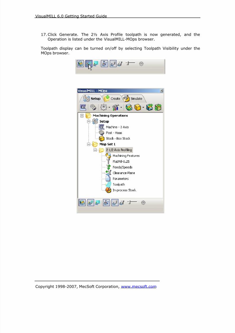
16. Click Generate. The 2½ Axis Profile toolpath is now generated and theOperation is listed under the VisualMILL-MOps browser.
Note: Toolpath display can be turned on/off by selecting Toolpath Visibility under theMOps browser.

8/16/2019 Visual Mill Getting Started Guide
http://slidepdf.com/reader/full/visual-mill-getting-started-guide 28/411
VisualMILL 6.0 Getting Started Guide
Copyright 1998-2007, MecSoft Corporation, www.mecsoft.com
8/16/2019 Visual Mill Getting Started Guide
http://slidepdf.com/reader/full/visual-mill-getting-started-guide 29/411
VisualMILL 6.0 Getting Started Guide
Copyright 1998-2007, MecSoft Corporation, www.mecsoft.com
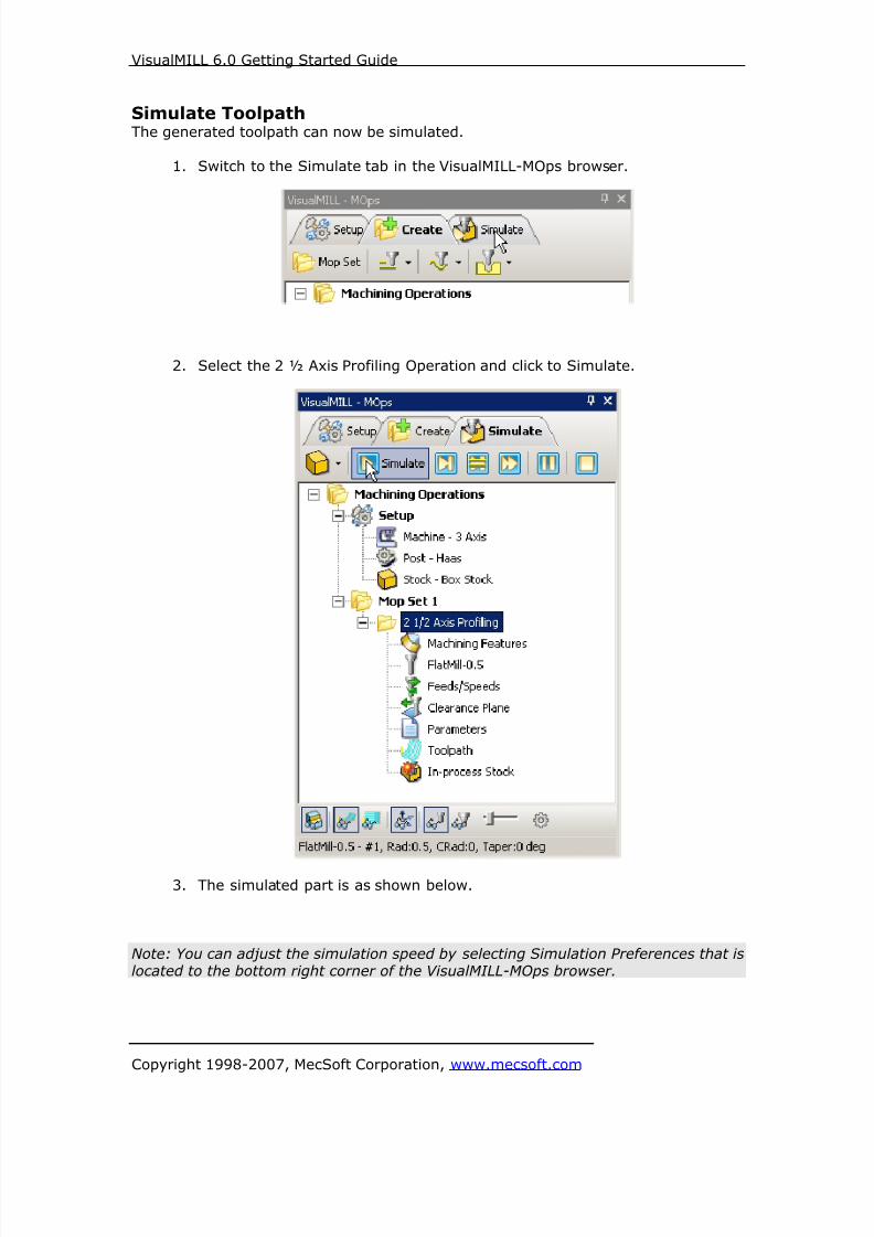
Simulate ToolpathThe generated toolpath can now be simulated.
1. Switch to the Simulate tab in the VisualMILL-MOps browser.
2. Select the 2 ½ Axis Profiling Operation and click to Simulate.
3. The simulated part is as shown below.
Note: You can adjust the simulation speed by selecting Simulation Preferences that islocated to the bottom right corner of the VisualMILL-MOps browser.

8/16/2019 Visual Mill Getting Started Guide
http://slidepdf.com/reader/full/visual-mill-getting-started-guide 30/411
VisualMILL 6.0 Getting Started Guide
Copyright 1998-2007, MecSoft Corporation, www.mecsoft.com
To exit the Simulation mode, pause the Simulation and click Exit Simulation. Thisswitches back to the Create Operations tab.
Creating a 2 ½ Axis Profile for the Outer Region
1. Switch to the Create Operation tab.
2. Select Profiling from the 2 ½ Axis operations menu.
3. Under Machining Features/ Regions, select Remove All.
4. Now click on Select Curves as Regions and select the Outer profile of the
Gasket as the region.
5. Right mouse click to complete the selection.
6. Switch to Tools tab and select FlatMill-0.5 as the active tool.

8/16/2019 Visual Mill Getting Started Guide
http://slidepdf.com/reader/full/visual-mill-getting-started-guide 31/411
VisualMILL 6.0 Getting Started Guide
Copyright 1998-2007, MecSoft Corporation, www.mecsoft.com
7. Under Feeds/Speeds select Load from Tool.
8. Set the Clearance control to Automatic.
9. Switch to Cut Parameters tab, check Use Outside/Inside for Closed
Curves, and set the Cut Start Side to Outside
10. Go over to Cut Levels and set the Total Cut Depth = 0.125.
11. Click Generate to Create the 2 ½ Axis Profile Toolpath.
12. The 2 ½ Axis Profile Operation is now created and is listed in the MOpsBrowser.

8/16/2019 Visual Mill Getting Started Guide
http://slidepdf.com/reader/full/visual-mill-getting-started-guide 32/411
VisualMILL 6.0 Getting Started Guide
Copyright 1998-2007, MecSoft Corporation, www.mecsoft.com
13. Switch to Simulate Tab, select 2 ½ Axis Profiling, and click to simulatetoolpath.

8/16/2019 Visual Mill Getting Started Guide
http://slidepdf.com/reader/full/visual-mill-getting-started-guide 33/411
VisualMILL 6.0 Getting Started Guide
Copyright 1998-2007, MecSoft Corporation, www.mecsoft.com
Reports
1. Switch to Create Operations Tab.
2. Select the MOp Set1 and right click and select Information.
This provides the estimated machining time for the operations created under MOpSet1.
Note: You can also go over to Machining Operations and right click and select
information determine the estimated machining time for all the MOp Sets.

8/16/2019 Visual Mill Getting Started Guide
http://slidepdf.com/reader/full/visual-mill-getting-started-guide 34/411
VisualMILL 6.0 Getting Started Guide
Copyright 1998-2007, MecSoft Corporation, www.mecsoft.com
Shop Docs
Shop documentation can be generated selecting Machining Operations under the
Create Operations tab. Right mouse click and Shop Documentation.User can select from one of the 2 templates and generate shop documentation. This
is saved as an html file and can be printed and handed over to the operator inpreparation for the part to be machined on the CNC.

8/16/2019 Visual Mill Getting Started Guide
http://slidepdf.com/reader/full/visual-mill-getting-started-guide 35/411
VisualMILL 6.0 Getting Started Guide
Copyright 1998-2007, MecSoft Corporation, www.mecsoft.com
Post Processing
1. Select Machining Operations from the Create Operations tab and right click
and select post process.
2. Specify the File Name as Gasket.nc and click Save.
The post by default is set to Haas as specified under the Post processor setup. You
can change the post processor by selecting a different one from the drop down menu

8/16/2019 Visual Mill Getting Started Guide
http://slidepdf.com/reader/full/visual-mill-getting-started-guide 36/411
VisualMILL 6.0 Getting Started Guide
Copyright 1998-2007, MecSoft Corporation, www.mecsoft.com
in the list. The posted g code by default will be saved to the folder where the part file
is located.
End of Tutorial 1!

8/16/2019 Visual Mill Getting Started Guide
http://slidepdf.com/reader/full/visual-mill-getting-started-guide 37/411
VisualMILL 6.0 Getting Started Guide
Copyright 1998-2007, MecSoft Corporation, www.mecsoft.com
Tutorial 2: Machining a Slotted Gear

8/16/2019 Visual Mill Getting Started Guide
http://slidepdf.com/reader/full/visual-mill-getting-started-guide 38/411
VisualMILL 6.0 Getting Started Guide
Copyright 1998-2007, MecSoft Corporation, www.mecsoft.com
Introduction
This tutorial will introduce the usage of 2 ½ axis profiling and Engraving Machining
Operations of VisualMill. We will be using the Gear.vcp part file.
It should be noted that, even though the part file contains a 3-D geometry
representing the part, we could machine this entirely by using just 2-D curves due to
the prismatic nature of this model.The stepped instructions are accompanied by explanatory and introductory text.
Reading this text will help you understand the tutorial methodology and provideinformation about additional options available. However, if you prefer to work
straight through the steps without any additional reading, look for the followingsymbol:
Don’t forget to save your work periodically! You may want to save the file under adifferent name so that the original file will be preserved.
Strategy to Machine the Slotted Gear
• We will machine the gear completely using 2 ½ axis-machining operations.
• We will use the Profiling operation to cut the outer shape of the gear and the
Engraving operation to cut the slots. The engraving option is preferred insituations where the cutter can be driven to create a slot that conforms to the
shape of the tool trajectory. This is because of the computational efficiency as
well as the accuracy of this method.• The part itself will be machined out of a 3 inch x 3 inch x ½ inch poplar wood
sheet.• The wooden sheet will be held to the machine table or the spoil sheet on the
table using double-sided tape.
• The part will be machined using a single ¼ inch flat end mill.
Main Programming StepsIn creating programs for each setup, the following steps will be followed:
• Create the Stock geometry
• Set the Machine zero point or Locate geometry with respect to the machine
coordinates
• Create / Select the tool used for machining
• Set the feeds and speeds• Set the clearance plane for the non-cutting transfer moves of the cutter
• Select the machining regions for containing the cutter to specific areas to cut
• Select the machining operations and set the parameters• Generate the toolpath
• Simulate the toolpath.
You may have to repeat either all or part of these steps for subsequent operations.

8/16/2019 Visual Mill Getting Started Guide
http://slidepdf.com/reader/full/visual-mill-getting-started-guide 39/411
VisualMILL 6.0 Getting Started Guide
Copyright 1998-2007, MecSoft Corporation, www.mecsoft.com
Preparing the part for Machining
Loading the Part Model “Part” refers to the geometry that represents the final manufactured product. You
can create parts within VisualMILL, but it is more typical to import geometry created
in another CAD system.
To load a part:
1. Select File / Open from the Menu, or click the Open icon from the Standard
bar.2. From the Open dialog box, select the Gear.vcp file from the Tutorials folder
in the VisualMILL 6.0 installation folder. (C:\Program Files\MecSoftCorporation\VisualCAM 1.0\Plug-ins\VisualMILL 6.0\Tutorials)
The imported part appears as shown below.

8/16/2019 Visual Mill Getting Started Guide
http://slidepdf.com/reader/full/visual-mill-getting-started-guide 40/411
VisualMILL 6.0 Getting Started Guide
Copyright 1998-2007, MecSoft Corporation, www.mecsoft.com
Setup Tab1. Go to the VisualMILL- MOps browser and click on the Setup tab.
2. Select Machine Setup from the setup tab.
3. Set the Machine type to 3 axis.

8/16/2019 Visual Mill Getting Started Guide
http://slidepdf.com/reader/full/visual-mill-getting-started-guide 41/411
VisualMILL 6.0 Getting Started Guide
Copyright 1998-2007, MecSoft Corporation, www.mecsoft.com
4. Select Post from the setup tab to specify the post processor options.
5. Set the current post processor that is on your controller. We will select Haasas the post processor for this exercise.
Note: By default post processor files are located under
C:\Program Files\MecSoft Corporation\VisualCAM 1.0\Plug-ins\VisualMill 6.0\Posts
8/16/2019 Visual Mill Getting Started Guide
http://slidepdf.com/reader/full/visual-mill-getting-started-guide 42/411
VisualMILL 6.0 Getting Started Guide
Copyright 1998-2007, MecSoft Corporation, www.mecsoft.com
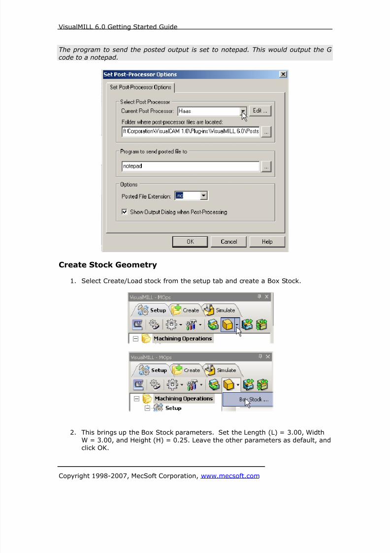
The program to send the posted output is set to notepad. This would output the G
code to a notepad.
Create Stock Geometry
1. Select Create/Load stock from the setup tab and create a Box Stock.
2. This brings up the Box Stock parameters. Set the Length (L) = 3.00, Width
W = 3.00, and Height (H) = 0.25. Leave the other parameters as default, andclick OK.

8/16/2019 Visual Mill Getting Started Guide
http://slidepdf.com/reader/full/visual-mill-getting-started-guide 43/411
VisualMILL 6.0 Getting Started Guide
Copyright 1998-2007, MecSoft Corporation, www.mecsoft.com
3. The stock geometry is now created, and a semi-transparent stock box isdisplayed on top of the part geometry.
4. The setup tab now displays the following information: Machine Type, Post
Processor, and Stock type as show below.
8/16/2019 Visual Mill Getting Started Guide
http://slidepdf.com/reader/full/visual-mill-getting-started-guide 44/411
VisualMILL 6.0 Getting Started Guide
Copyright 1998-2007, MecSoft Corporation, www.mecsoft.com
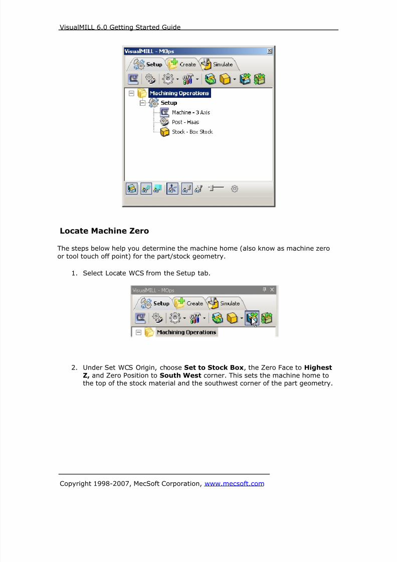
Locate Machine Zero
The steps below help you determine the machine home (also know as machine zero
or tool touch off point) for the part/stock geometry.
1. Select Locate WCS from the Setup tab.
2. Under Set WCS Origin, choose Set to Stock Box, the Zero Face to Highest
Z, and Zero Position to South West corner. This sets the machine home tothe top of the stock material and the southwest corner of the part geometry.

8/16/2019 Visual Mill Getting Started Guide
http://slidepdf.com/reader/full/visual-mill-getting-started-guide 45/411
VisualMILL 6.0 Getting Started Guide
Copyright 1998-2007, MecSoft Corporation, www.mecsoft.com
Note: You can change the stock model transparency under standard mode byselecting Simulation Preferences that is located at the bottom of the MOps browser.

8/16/2019 Visual Mill Getting Started Guide
http://slidepdf.com/reader/full/visual-mill-getting-started-guide 46/411
VisualMILL 6.0 Getting Started Guide
Copyright 1998-2007, MecSoft Corporation, www.mecsoft.com
Create Tools
To machine the above part we will now create a ¼ inch (0.25”) Flat End Mill.
1. Go to the VisualMILL-Tools browser that is located below the VisualMILL-MOps
browser and select Create/Edit Tools. Select the Tool Type to Flat End Mill.
2. Set the tool name as FlatMill-0.25, Tool Diameter = 0.25. Under theProperties tab, set Tool Number = 1.
8/16/2019 Visual Mill Getting Started Guide
http://slidepdf.com/reader/full/visual-mill-getting-started-guide 47/411
VisualMILL 6.0 Getting Started Guide
Copyright 1998-2007, MecSoft Corporation, www.mecsoft.com
Setting Feeds and Speeds
You can assign Feeds & Speeds to a tool or you can load from a table. In this
exercise we will assign feeds and speeds to the tool.
3. Switch to the Feeds & Speeds tab inside the create/select tool dialog.
4. Use the following settings for feeds and speeds.
5. Click Save as New Tool. The tool is now created and listed under Tools inLibrary. Click OK to close the dialog.
Note: You can edit the tool properties and click Save Edits to Tool to save the
changes. You can create additional tools by assigning a different name and specifythe tool parameters.
The created tools are now listed under the VisualMILL-Tools browser.
8/16/2019 Visual Mill Getting Started Guide
http://slidepdf.com/reader/full/visual-mill-getting-started-guide 48/411
VisualMILL 6.0 Getting Started Guide
Copyright 1998-2007, MecSoft Corporation, www.mecsoft.com
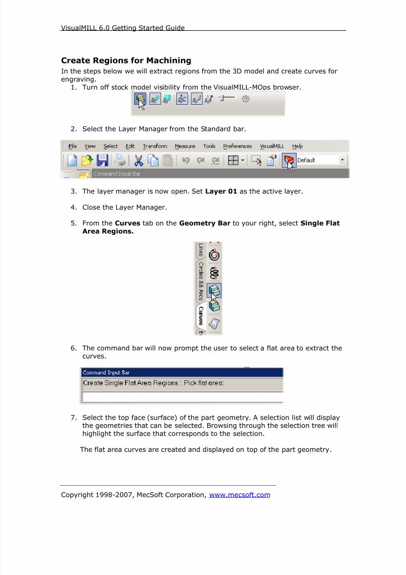
Create Regions for Machining
In the steps below we will extract regions from the 3D model and create curves for
engraving.
1. Turn off stock model visibility from the VisualMILL-MOps browser.
2. Select the Layer Manager from the Standard bar.
3. The layer manager is now open. Set Layer 01 as the active layer.
4. Close the Layer Manager.
5. From the Curves tab on the Geometry Bar to your right, select Single Flat
Area Regions.
6. The command bar will now prompt the user to select a flat area to extract thecurves.
7. Select the top face (surface) of the part geometry. A selection list will displaythe geometries that can be selected. Browsing through the selection tree will
highlight the surface that corresponds to the selection.
The flat area curves are created and displayed on top of the part geometry.

8/16/2019 Visual Mill Getting Started Guide
http://slidepdf.com/reader/full/visual-mill-getting-started-guide 49/411
VisualMILL 6.0 Getting Started Guide
Copyright 1998-2007, MecSoft Corporation, www.mecsoft.com
8. Switch to the Top view and create a circle using Center and Radius.9. Select Circles & Arcs from the Geometry Bar and pick Circle Center & Radius.
10. Specify 1.5,1.5 as the center coordinates and hit the enter key.
11. Specify 0.99 as the radius of the circle and hit the enter key
We will now create lines, which can be selected for engraving the slots on thegear.
12. Turn on the Mid Point and Quad Point snap from the status bar and turn off
the other snaps.

8/16/2019 Visual Mill Getting Started Guide
http://slidepdf.com/reader/full/visual-mill-getting-started-guide 50/411
VisualMILL 6.0 Getting Started Guide
Copyright 1998-2007, MecSoft Corporation, www.mecsoft.com
13. Switch to the Top view and select Lines from the Geometry Bar and pick
Create Line.
14. For the first coordinate, snap to the quad point on the circle as show below.
15. For the second coordinate, snap to the center of the arc as shown below. A
line is now created at the center of the slot.
We will now array the line across other slots on the gear.
8/16/2019 Visual Mill Getting Started Guide
http://slidepdf.com/reader/full/visual-mill-getting-started-guide 51/411
VisualMILL 6.0 Getting Started Guide
Copyright 1998-2007, MecSoft Corporation, www.mecsoft.com
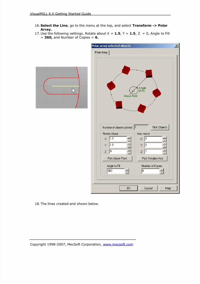
16.Select the Line, go to the menu at the top, and select Transform -> Polar
Array.
17. Use the following settings. Rotate about X = 1.5, Y = 1.5, Z = 0, Angle to Fill= 360, and Number of Copies = 6.
18. The lines created and shown below.
8/16/2019 Visual Mill Getting Started Guide
http://slidepdf.com/reader/full/visual-mill-getting-started-guide 52/411
VisualMILL 6.0 Getting Started Guide
Copyright 1998-2007, MecSoft Corporation, www.mecsoft.com
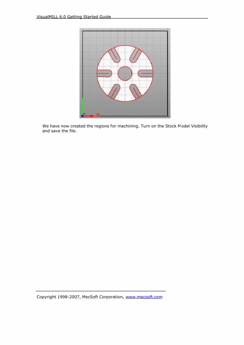
We have now created the regions for machining. Turn on the Stock Model Visibility
and save the file.

8/16/2019 Visual Mill Getting Started Guide
http://slidepdf.com/reader/full/visual-mill-getting-started-guide 53/411
VisualMILL 6.0 Getting Started Guide
Copyright 1998-2007, MecSoft Corporation, www.mecsoft.com
Create Machining Operations
In this process we will create a 2.5 axis profiling operation.
1. Switch to the Create Operations tab in VisualMILL-Mops browser.
2 ½ Axis Profiling
2. Select 2.5 Axis Mill and choose Profiling.
This brings up the 2 ½ Axis Profiling Operations dialog. We will go over thesteps for creating the profile operations.

8/16/2019 Visual Mill Getting Started Guide
http://slidepdf.com/reader/full/visual-mill-getting-started-guide 54/411
VisualMILL 6.0 Getting Started Guide
Copyright 1998-2007, MecSoft Corporation, www.mecsoft.com
Select Machining Features/Regions3. Go to the Machining Features/ Regions tab and click Select Curves as
Regions
4. Now select the inner circle first by using the left mouse click and then theouter circle.
8/16/2019 Visual Mill Getting Started Guide
http://slidepdf.com/reader/full/visual-mill-getting-started-guide 55/411
VisualMILL 6.0 Getting Started Guide
Copyright 1998-2007, MecSoft Corporation, www.mecsoft.com
5. Right mouse click or select enter from the keypad to complete the selection.6. The selected regions are now displayed under Machining Regions.

8/16/2019 Visual Mill Getting Started Guide
http://slidepdf.com/reader/full/visual-mill-getting-started-guide 56/411

8/16/2019 Visual Mill Getting Started Guide
http://slidepdf.com/reader/full/visual-mill-getting-started-guide 57/411
8/16/2019 Visual Mill Getting Started Guide
http://slidepdf.com/reader/full/visual-mill-getting-started-guide 58/411
VisualMILL 6.0 Getting Started Guide
Copyright 1998-2007, MecSoft Corporation, www.mecsoft.com
Clearance Control11. Switch to Clearance Tab.
12. Set the Clearance Plane Definition to Automatic and Cut Transfer Method to
Clearance Plane.VisualMILL will determine a safe Z height for the Entry & Exit when set to
automatic. Setting Cut Transfer to Clearance Plane would apply the automaticZ clearance between transfers when the tool moves from a machining region to
another.
8/16/2019 Visual Mill Getting Started Guide
http://slidepdf.com/reader/full/visual-mill-getting-started-guide 59/411
8/16/2019 Visual Mill Getting Started Guide
http://slidepdf.com/reader/full/visual-mill-getting-started-guide 60/411
VisualMILL 6.0 Getting Started Guide
Copyright 1998-2007, MecSoft Corporation, www.mecsoft.com
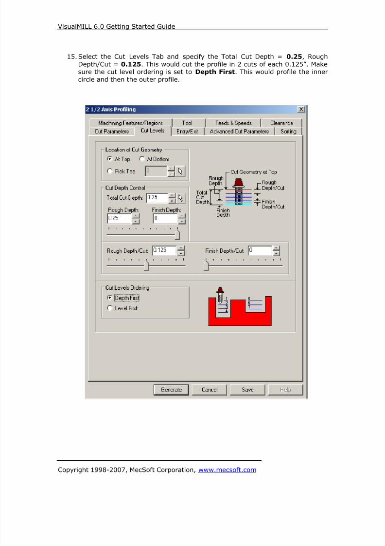
15. Select the Cut Levels Tab and specify the Total Cut Depth = 0.25, Rough
Depth/Cut = 0.125. This would cut the profile in 2 cuts of each 0.125”. Makesure the cut level ordering is set to Depth First. This would profile the inner
circle and then the outer profile.

8/16/2019 Visual Mill Getting Started Guide
http://slidepdf.com/reader/full/visual-mill-getting-started-guide 61/411
VisualMILL 6.0 Getting Started Guide
Copyright 1998-2007, MecSoft Corporation, www.mecsoft.com
Entry/Exit
16. Switch to Entry/Exit Tab, and Set the Entry and Exit Type to None.
8/16/2019 Visual Mill Getting Started Guide
http://slidepdf.com/reader/full/visual-mill-getting-started-guide 62/411
VisualMILL 6.0 Getting Started Guide
Copyright 1998-2007, MecSoft Corporation, www.mecsoft.com
17. Click Generate. The 2½ Axis Profile toolpath is now generated, and the
Operation is listed under the VisualMILL-MOps browser.
Toolpath display can be turned on/off by selecting Toolpath Visibility under the
MOps browser.

8/16/2019 Visual Mill Getting Started Guide
http://slidepdf.com/reader/full/visual-mill-getting-started-guide 63/411
VisualMILL 6.0 Getting Started Guide
Copyright 1998-2007, MecSoft Corporation, www.mecsoft.com
Simulate Toolpath
The generated toolpath can now be simulated.
1. Switch to the Simulate tab in the VisualMILL-MOps browser.
2. Select the 2 ½ Axis Profiling Operation and click to Simulate.

8/16/2019 Visual Mill Getting Started Guide
http://slidepdf.com/reader/full/visual-mill-getting-started-guide 64/411
VisualMILL 6.0 Getting Started Guide
Copyright 1998-2007, MecSoft Corporation, www.mecsoft.com
3. The simulated part is as shown below.
Note: You can adjust the simulation speed by selecting Simulation Preferences that islocated to the bottom right corner of the VisualMILL-MOps browser.

8/16/2019 Visual Mill Getting Started Guide
http://slidepdf.com/reader/full/visual-mill-getting-started-guide 65/411
VisualMILL 6.0 Getting Started Guide
Copyright 1998-2007, MecSoft Corporation, www.mecsoft.com
To exit the Simulation mode, pause the Simulation, and click Exit Simulation. Thisswitches back to the Create Operations tab.
Creating an Engraving Operation
Now we will use engraving operation to cut the slots of the gear by driving the 0.25
inch tool in the slot. As already mentioned, the most efficient way of machining slotsis to use the Engraving option and drive the cutter along the center of the slot.
1. Switch to the Create Operation tab.
2. Select Engraving from the 2 ½ Axis operations menu.

8/16/2019 Visual Mill Getting Started Guide
http://slidepdf.com/reader/full/visual-mill-getting-started-guide 66/411
VisualMILL 6.0 Getting Started Guide
Copyright 1998-2007, MecSoft Corporation, www.mecsoft.com
Select Machining Regions
3. Under Machining Features/ Regions click on Remove All to deselect any
regions that could have been selected from the previous machining operation.
4. Now click on Select Curves as Regions and select the 6 lines on the slottedgear as shown below.

8/16/2019 Visual Mill Getting Started Guide
http://slidepdf.com/reader/full/visual-mill-getting-started-guide 67/411
VisualMILL 6.0 Getting Started Guide
Copyright 1998-2007, MecSoft Corporation, www.mecsoft.com
5. Right mouse click to complete the selection.
6. The 6 selected regions are listed under the Machining Features/Regions
Select Tool
7. Switch to Tools tab and select FlatMill-0.25 as the active tool.
8. Under Feeds/Speeds, select Load from Tool.
9. Set the Clearance control to Automatic.
Specify Engraving Cut Parameters
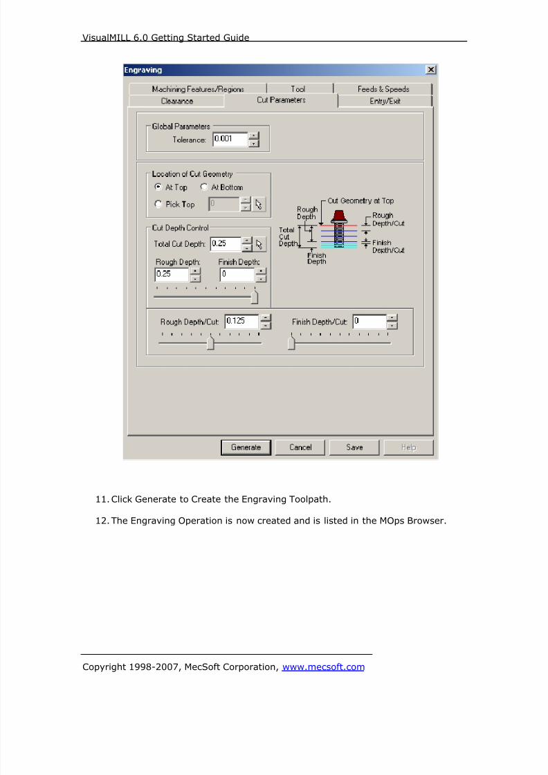
10. Switch to Cut Parameters tab. Under Cut Depth Control, set the Total CutDepth = 0.25, Rough Depth = 0.25, and Rough Depth/Cut = 0.125.
8/16/2019 Visual Mill Getting Started Guide
http://slidepdf.com/reader/full/visual-mill-getting-started-guide 68/411
VisualMILL 6.0 Getting Started Guide
Copyright 1998-2007, MecSoft Corporation, www.mecsoft.com
11. Click Generate to Create the Engraving Toolpath.
12. The Engraving Operation is now created and is listed in the MOps Browser.

8/16/2019 Visual Mill Getting Started Guide
http://slidepdf.com/reader/full/visual-mill-getting-started-guide 69/411
VisualMILL 6.0 Getting Started Guide
Copyright 1998-2007, MecSoft Corporation, www.mecsoft.com
8/16/2019 Visual Mill Getting Started Guide
http://slidepdf.com/reader/full/visual-mill-getting-started-guide 70/411
VisualMILL 6.0 Getting Started Guide
Copyright 1998-2007, MecSoft Corporation, www.mecsoft.com
Simulate Toolpath
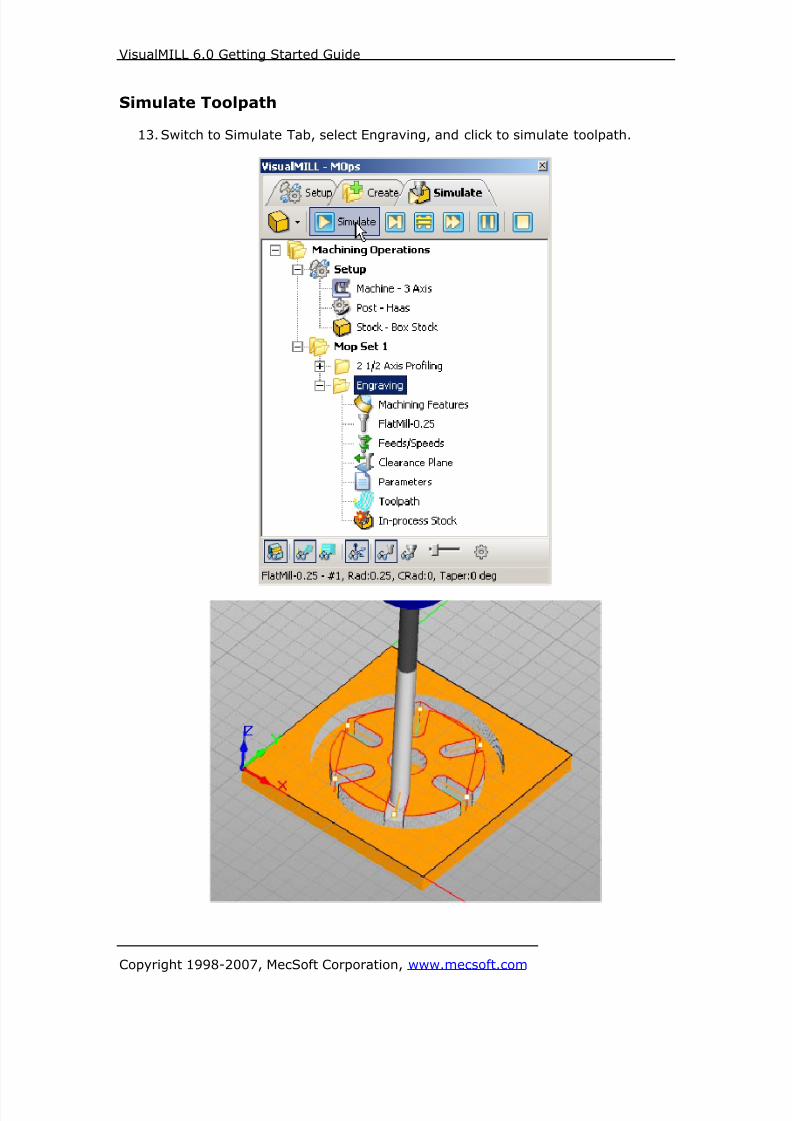
13. Switch to Simulate Tab, select Engraving, and click to simulate toolpath.

8/16/2019 Visual Mill Getting Started Guide
http://slidepdf.com/reader/full/visual-mill-getting-started-guide 71/411

8/16/2019 Visual Mill Getting Started Guide
http://slidepdf.com/reader/full/visual-mill-getting-started-guide 72/411
VisualMILL 6.0 Getting Started Guide
Copyright 1998-2007, MecSoft Corporation, www.mecsoft.com
The post by default is set to Haas as specified under the Post processor setup. You
can change the post processor by selecting a different one from the drop down menu
in the list. The posted g code by default will be saved to the folder where the part fileis located.
End of Tutorial 2!

8/16/2019 Visual Mill Getting Started Guide
http://slidepdf.com/reader/full/visual-mill-getting-started-guide 73/411
VisualMILL 6.0 Getting Started Guide
Copyright 1998-2007, MecSoft Corporation, www.mecsoft.com
Tutorial 3: Machining a Shaft Base

8/16/2019 Visual Mill Getting Started Guide
http://slidepdf.com/reader/full/visual-mill-getting-started-guide 74/411
VisualMILL 6.0 Getting Started Guide
Copyright 1998-2007, MecSoft Corporation, www.mecsoft.com
Introduction
This tutorial will illustrate machining of a prismatic part such as this Shaft Base using
2-1/2 milling operations. Even though we have created a 3-D representation of thepart, it will be seen later on that we can machine this using just 2-D curves. The
reason we are able to do this is because of the prismatic nature of this model. Thistutorial will introduce the usage of 2 ½ axis machining for a simple one sided part.
We will use profiling, pocketing and hole pocketing operations.The stepped instructions are accompanied by explanatory and introductory text.
Reading this text will help you understand the tutorial methodology and provide
information about additional options available.
Don’t forget to save your work periodically! You may want to save the file under adifferent name so that the original file will be preserved.
Strategy to Machine the Shaft Base
• We will machine the shaft base completely using 2 ½ axis-machiningoperations.
• The starting material for the Shaft Base is soft wood and the size is 5.5 x 3.25
x 0.75 inches.
• The wooden sheet will be held to the machine table or the spoil sheet on the
table using double-sided tape.
• The part will be machined using a single ¼ inch flat end mill.• Determining the sequence of machining operations
o As the part thickness is 0.625” thick and the available stock is 0.75”the first operation would involve reducing the thickness of the stock
over the entire area from 0.75 to 0.625. To carry out this operation wewill use the 2 ½ axis Facing Operation as the toolpath extends past the
region.o The next step would involve machining the areas around and inside
the boss. As the thickness of material to be removed is not the same
for both the areas we would have to use 2 separate operations to clearthe material. We will use 2 ½ axis Pocketing Operation which is ideal
removing material inside a specified region.o We are now down to the level where the step holes need to be
machined. As the holes are circular we will use 2 ½ axis HolePocketing operation to machine the holes to its depth in 2 separate
operations.o The 2 inner holes can be drilled using an engraving operation to its
depth.
o Finally we will cut out the shape of the part from the rectangular using
a contour toolpath. This is accomplished using a 2 ½ axis ProfilingOperation which separates the finished part from the stock material.
Main Programming StepsIn creating programs for each setup, the following steps will be followed:
• Create the Stock geometry
• Set the Machine zero point or Locate geometry with respect to the machinecoordinates
• Create / Select the tool used for machining
8/16/2019 Visual Mill Getting Started Guide
http://slidepdf.com/reader/full/visual-mill-getting-started-guide 75/411
VisualMILL 6.0 Getting Started Guide
Copyright 1998-2007, MecSoft Corporation, www.mecsoft.com
• Set the feeds and speeds
• Set the clearance plane for the non-cutting transfer moves of the cutter
• Select the machining regions for containing the cutter to specific areas to cut
• Select the machining operations and set the parameters
• Generate the toolpath
• Simulate the toolpath.
You may have to repeat either all or part of these steps for subsequent operations.
Preparing the part for Machining
Loading the Part Model
“Part” refers to the geometry that represents the final manufactured product. Youcan create parts within VisualMILL, but it is more typical to import geometry created
in another CAD system.
To load a part:
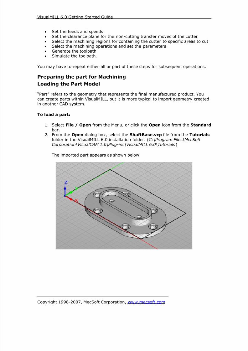
1. Select File / Open from the Menu, or click the Open icon from the Standard
bar.2. From the Open dialog box, select the ShaftBase.vcp file from the Tutorials
folder in the VisualMILL 6.0 installation folder. (C:\Program Files\MecSoftCorporation\VisualCAM 1.0\Plug-ins\VisualMILL 6.0\Tutorials)
The imported part appears as shown below

8/16/2019 Visual Mill Getting Started Guide
http://slidepdf.com/reader/full/visual-mill-getting-started-guide 76/411
VisualMILL 6.0 Getting Started Guide
Copyright 1998-2007, MecSoft Corporation, www.mecsoft.com
Setup Tab
1. Go to the VisualMILL- MOps browser and click on the Setup tab.
2. Select Machine Setup from the setup tab.
3. Set the Machine type to 3 axis.
8/16/2019 Visual Mill Getting Started Guide
http://slidepdf.com/reader/full/visual-mill-getting-started-guide 77/411
VisualMILL 6.0 Getting Started Guide
Copyright 1998-2007, MecSoft Corporation, www.mecsoft.com
4. Select Post from the setup tab to specify the post processor options.
5. Set the current post processor that is on your controller. We will select Haasas the post processor for this exercise.
Note: By default post processor files are located under
C:\Program Files\MecSoft Corporation\VisualCAM 1.0\Plug-ins\VisualMill 6.0\Posts
The program to send the posted output is set to notepad. This would output the G
code to a notepad.
8/16/2019 Visual Mill Getting Started Guide
http://slidepdf.com/reader/full/visual-mill-getting-started-guide 78/411
VisualMILL 6.0 Getting Started Guide
Copyright 1998-2007, MecSoft Corporation, www.mecsoft.com
Create Stock Geometry
1. Select Create/Load stock from the setup tab and create a Box Stock.
2. This brings up the Box Stock parameters. Set the Length (L) = 5.50, Width
W = 3.25, and Height (H) = 0.75. Leave the other parameters as default, andclick OK.

8/16/2019 Visual Mill Getting Started Guide
http://slidepdf.com/reader/full/visual-mill-getting-started-guide 79/411
VisualMILL 6.0 Getting Started Guide
Copyright 1998-2007, MecSoft Corporation, www.mecsoft.com
3. The stock geometry is now created, and a semi-transparent stock box isdisplayed on top of the part geometry.

8/16/2019 Visual Mill Getting Started Guide
http://slidepdf.com/reader/full/visual-mill-getting-started-guide 80/411
VisualMILL 6.0 Getting Started Guide
Copyright 1998-2007, MecSoft Corporation, www.mecsoft.com
4. The setup tab now displays the following information: Machine Type, Post
Processor, and Stock type as show below.
Locate Machine Zero
1. The steps below help you determine the machine home (also know as
machine zero or tool touch off point) for the part/stock geometry.
2. Select Locate WCS from the Setup tab.
3. Under Set WCS Origin, choose Set to Stock Box, the Zero Face to Highest
Z, and Zero Position to South West corner. This sets the machine home tothe top of the stock material and the southwest corner of the part geometry.

8/16/2019 Visual Mill Getting Started Guide
http://slidepdf.com/reader/full/visual-mill-getting-started-guide 81/411
VisualMILL 6.0 Getting Started Guide
Copyright 1998-2007, MecSoft Corporation, www.mecsoft.com
Note: You can change the stock model transparency under standard mode byselecting Simulation Preferences that is located at the bottom of the MOps browser.

8/16/2019 Visual Mill Getting Started Guide
http://slidepdf.com/reader/full/visual-mill-getting-started-guide 82/411

8/16/2019 Visual Mill Getting Started Guide
http://slidepdf.com/reader/full/visual-mill-getting-started-guide 83/411
VisualMILL 6.0 Getting Started Guide
Copyright 1998-2007, MecSoft Corporation, www.mecsoft.com
Front View
Top View

8/16/2019 Visual Mill Getting Started Guide
http://slidepdf.com/reader/full/visual-mill-getting-started-guide 84/411
VisualMILL 6.0 Getting Started Guide
Copyright 1998-2007, MecSoft Corporation, www.mecsoft.com
Create Tools
To machine the above part we will now create a ¼ inch (0.25”) Flat End Mill.
1. Go to the VisualMILL-Tools browser that is located below the VisualMILL-MOps browser and select Create/Edit Tools. Select the Tool Type to Flat End
Mill.
2. Set the tool name as FlatMill-0.25 and Tool Diameter = 0.25. Under theProperties tab, set Tool Number = 1.

8/16/2019 Visual Mill Getting Started Guide
http://slidepdf.com/reader/full/visual-mill-getting-started-guide 85/411
VisualMILL 6.0 Getting Started Guide
Copyright 1998-2007, MecSoft Corporation, www.mecsoft.com
Setting Feeds and Speeds
You can assign Feeds & Speeds to a tool or you can load from a table. In this
exercise, we will assign feeds and speeds to the tool.
3. Switch to the Feeds & Speeds tab inside the create/select tool dialog.
4. Use the following settings for feeds and speeds.
5. Click Save as New Tool. The tool is now created and listed under Tools inLibrary. Click OK to close the dialog.
Note: You can edit the tool properties and click Save Edits to Tool to save the
changes. You can create additional tools by assigning a different name and specifythe tool parameters.
The created tools are now listed under the VisualMILL-Tools browser.

8/16/2019 Visual Mill Getting Started Guide
http://slidepdf.com/reader/full/visual-mill-getting-started-guide 86/411
VisualMILL 6.0 Getting Started Guide
Copyright 1998-2007, MecSoft Corporation, www.mecsoft.com
Create Machining Operations
We will machine the Shaft Base using 4 different machining operations – Facing,
Pocketing, Hole Pocketing and Engraving.
The stock geometry has a thickness of 0.75” and the finished part is 0.625”. We willcreate a 2.5 axis facing operation to mill the 0.125” thickness of material from the
stock geometry.
1. Switch to the Create Operations tab in VisualMILL-Mops browser.
2 ½ Axis Facing
1. Select 2.5 Axis Milling and choose Facing.
2. This brings up the 2 ½ Axis Facing Operation Dialog. We will now go over
the steps for creating the toolpath.
8/16/2019 Visual Mill Getting Started Guide
http://slidepdf.com/reader/full/visual-mill-getting-started-guide 87/411
VisualMILL 6.0 Getting Started Guide
Copyright 1998-2007, MecSoft Corporation, www.mecsoft.com
Select Machining Features/Regions
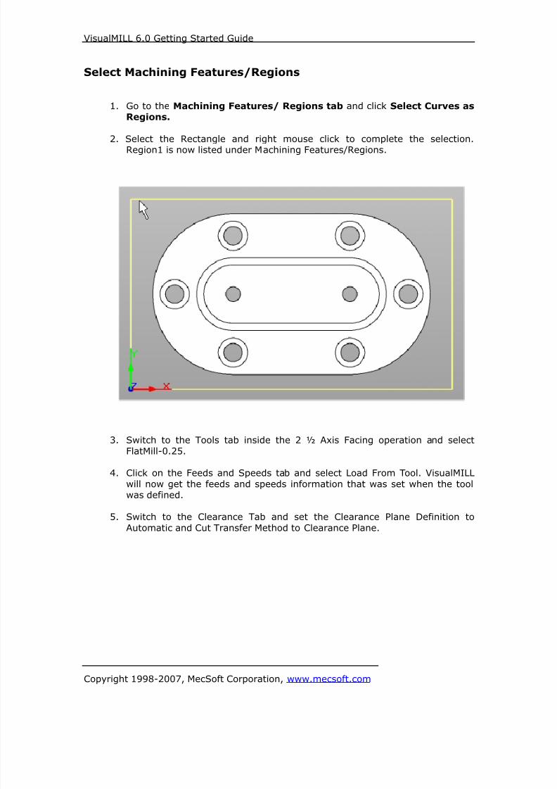
1. Go to the Machining Features/ Regions tab and click Select Curves asRegions.
2. Select the Rectangle and right mouse click to complete the selection.Region1 is now listed under Machining Features/Regions.
3. Switch to the Tools tab inside the 2 ½ Axis Facing operation and select
FlatMill-0.25.
4. Click on the Feeds and Speeds tab and select Load From Tool. VisualMILL
will now get the feeds and speeds information that was set when the toolwas defined.
5. Switch to the Clearance Tab and set the Clearance Plane Definition to
Automatic and Cut Transfer Method to Clearance Plane.

8/16/2019 Visual Mill Getting Started Guide
http://slidepdf.com/reader/full/visual-mill-getting-started-guide 88/411
VisualMILL 6.0 Getting Started Guide
Copyright 1998-2007, MecSoft Corporation, www.mecsoft.com
Specify Cut Parameters
1. Click on the Roughing tab.
2. Set the Tolerance to 0.01, Stock to leave to 0, Cut Pattern to IslandOffset Cuts, and Step Distance to 50 (% Tool Diameter).
3. Switch to the Cut Levels Tab.

8/16/2019 Visual Mill Getting Started Guide
http://slidepdf.com/reader/full/visual-mill-getting-started-guide 89/411
VisualMILL 6.0 Getting Started Guide
Copyright 1998-2007, MecSoft Corporation, www.mecsoft.com
4. Use the Following Settings.
a. Pick Top = 0 (As the selected region at Z = -0.125”, we would need
to start the first cut from Z =0).b. Total Cut Depth = 0.125, Rough Depth = 0.125, and Rough
Depth/Cut = 0.0625.
5. Switch to the Entry/Exit tab and set the Entry and Exit parameters to none.
6. Click Generate. The 2½ Axis Facing toolpath is now generated, and the
Operation is listed under the VisualMILL-MOps browser.

8/16/2019 Visual Mill Getting Started Guide
http://slidepdf.com/reader/full/visual-mill-getting-started-guide 90/411
VisualMILL 6.0 Getting Started Guide
Copyright 1998-2007, MecSoft Corporation, www.mecsoft.com
7. Switch to Simulate tab, Select 2 ½ Axis Facing, and click Simulate to run
the simulation.

8/16/2019 Visual Mill Getting Started Guide
http://slidepdf.com/reader/full/visual-mill-getting-started-guide 91/411
VisualMILL 6.0 Getting Started Guide
Copyright 1998-2007, MecSoft Corporation, www.mecsoft.com
2 ½ Axis Pocketing
We will now use 2½ axis Pocketing operation to machine the area inside the boss.
Preparing the part for Pocketing
In Preparation for the pocketing Operation, we will now create regions by extracting
curves from the 3D model.
1. Turn off the Stock Model and Toolpath Visibility from the VisualMILL-MOpsbrowser.
2. Open Layer Manager and Select Layer 01 as the Active Layer.
3. Click on the Geometry Bar and select the Curves Tab. Select Single Flat Area
Region.

8/16/2019 Visual Mill Getting Started Guide
http://slidepdf.com/reader/full/visual-mill-getting-started-guide 92/411
VisualMILL 6.0 Getting Started Guide
Copyright 1998-2007, MecSoft Corporation, www.mecsoft.com
4. The command bar would now prompt the user to select a flat area to extract
the curves
5. Pick the flat area as shown below.
6. Flat area curves are created and are on Layer 01.
We are now ready to create the pocketing operation for the inner region.
7. Switch to the Create Operations tab.

8/16/2019 Visual Mill Getting Started Guide
http://slidepdf.com/reader/full/visual-mill-getting-started-guide 93/411
VisualMILL 6.0 Getting Started Guide
Copyright 1998-2007, MecSoft Corporation, www.mecsoft.com
Creating the Pocketing Operation #11. From the Create Operations tab, select 2½ axis Milling and Pocketing.
This brings up the 2 ½ Axis Pocketing Operations dialog. We will go over thesteps for creating the pocketing operation.
2. Go to the Machining Features/ Regions tab and click Select Curves asRegions.
3. Select the curve and right mouse click to complete the selection. Region1 isnow listed under Machining Features/Regions.
4. Switch to the Tools tab inside the 2½ Axis Pocketing operation and select
FlatMill-0.25.
5. Click on the Feeds and Speeds tab and select Load From Tool. VisualMILL willnow get the feeds and speeds information that was set when the tool was
defined.
6. Switch to the Clearance Tab and set the Clearance Plane Definition toAutomatic and Cut Transfer Method to Clearance Plane.
8/16/2019 Visual Mill Getting Started Guide
http://slidepdf.com/reader/full/visual-mill-getting-started-guide 94/411
VisualMILL 6.0 Getting Started Guide
Copyright 1998-2007, MecSoft Corporation, www.mecsoft.com
Specify Cut Parameters
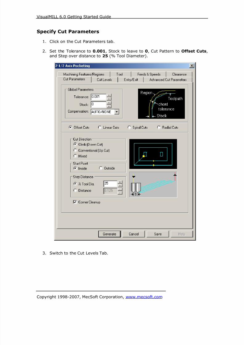
1. Click on the Cut Parameters tab.
2. Set the Tolerance to 0.001, Stock to leave to 0, Cut Pattern to Offset Cuts,and Step over distance to 25 (% Tool Diameter).
3. Switch to the Cut Levels Tab.

8/16/2019 Visual Mill Getting Started Guide
http://slidepdf.com/reader/full/visual-mill-getting-started-guide 95/411
VisualMILL 6.0 Getting Started Guide
Copyright 1998-2007, MecSoft Corporation, www.mecsoft.com
4. Use the Following Settings.
a. Location of Cut Geometry at Bottom (As the selected region is at the
bottom of the part, and we need to cut above it).
We will determine the Total Cut Depth from the 3D model by snappingat 2 points.
b. Select the Depth measuring tool located to the right of Total CutDepth. This will minimize the Pocketing Operation parameters
dialog.
c. Turn on the End Point Snap from the Status bar.
d. Pick the top of the boss as the start point and the bottom of the boss
as the end point as shown below.
e. The pocketing operation dialog shows up and determines Total CutDepth = 0.25.
f. Set the Rough Depth = 0.25 and Rough Depth/Cut = 0.05.

8/16/2019 Visual Mill Getting Started Guide
http://slidepdf.com/reader/full/visual-mill-getting-started-guide 96/411
VisualMILL 6.0 Getting Started Guide
Copyright 1998-2007, MecSoft Corporation, www.mecsoft.com
This would machine the pocket in steps of 0.05 resulting in 5 cut levels.
Note: You can also specify the Total Cut Depth by entering the depth values underTotal Cut Depth.

8/16/2019 Visual Mill Getting Started Guide
http://slidepdf.com/reader/full/visual-mill-getting-started-guide 97/411
VisualMILL 6.0 Getting Started Guide
Copyright 1998-2007, MecSoft Corporation, www.mecsoft.com
5. Switch to the Entry/Exit tab.
6. Use the following settings for Entry/Exit. Make sure to check Apply Entry/Exit
at all cut levels.
7. Click Generate. The 2½ Axis Pocketing toolpath is now generated and the
Operation is listed under the 2 ½ Axis Facing Operation in the VisualMILL-
MOps browser.
Note: You can rearrange the operations in the MOps browser by selecting the
operation and dragging and dropping.
8/16/2019 Visual Mill Getting Started Guide
http://slidepdf.com/reader/full/visual-mill-getting-started-guide 98/411
VisualMILL 6.0 Getting Started Guide
Copyright 1998-2007, MecSoft Corporation, www.mecsoft.com
8. Switch to Simulate tab, select 2 ½ Axis Pocketing, and click Simulate to runthe simulation.
8/16/2019 Visual Mill Getting Started Guide
http://slidepdf.com/reader/full/visual-mill-getting-started-guide 99/411
VisualMILL 6.0 Getting Started Guide
Copyright 1998-2007, MecSoft Corporation, www.mecsoft.com
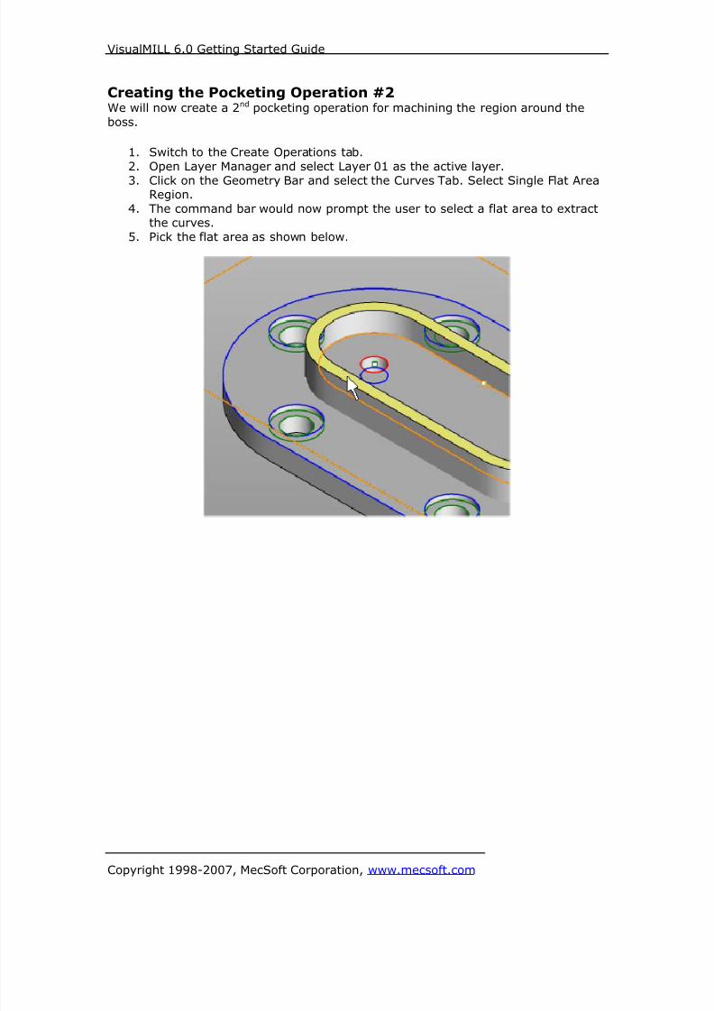
Creating the Pocketing Operation #2We will now create a 2nd pocketing operation for machining the region around the
boss.
1. Switch to the Create Operations tab.
2. Open Layer Manager and select Layer 01 as the active layer.
3. Click on the Geometry Bar and select the Curves Tab. Select Single Flat AreaRegion.
4. The command bar would now prompt the user to select a flat area to extractthe curves.
5. Pick the flat area as shown below.

8/16/2019 Visual Mill Getting Started Guide
http://slidepdf.com/reader/full/visual-mill-getting-started-guide 100/411
VisualMILL 6.0 Getting Started Guide
Copyright 1998-2007, MecSoft Corporation, www.mecsoft.com
Copying a MOp1. Switch to the Create operations tab.
2. Select the 2 ½ axis Pocketing Operation created from the previous step, rightmouse click, and select Copy.
3. Right click and select Paste.
4. This would create a copy of the 2 ½ axis Pocketing Operation listed below thefirst pocketing operation as show below.

8/16/2019 Visual Mill Getting Started Guide
http://slidepdf.com/reader/full/visual-mill-getting-started-guide 101/411
VisualMILL 6.0 Getting Started Guide
Copyright 1998-2007, MecSoft Corporation, www.mecsoft.com
5. Expand the 2 ½ Axis Pocketing (1) folder and double click on Machining
Features.

8/16/2019 Visual Mill Getting Started Guide
http://slidepdf.com/reader/full/visual-mill-getting-started-guide 102/411
VisualMILL 6.0 Getting Started Guide
Copyright 1998-2007, MecSoft Corporation, www.mecsoft.com
6. Click Remove All under Machining Features and click Select Curves as
Regions.
7. Select the rectangle and curve and right mouse click to complete the selection.
8. Region1 & Region2 are now listed under Machining Features/Regions. Click
Save to Close the Machining Regions Dialog.
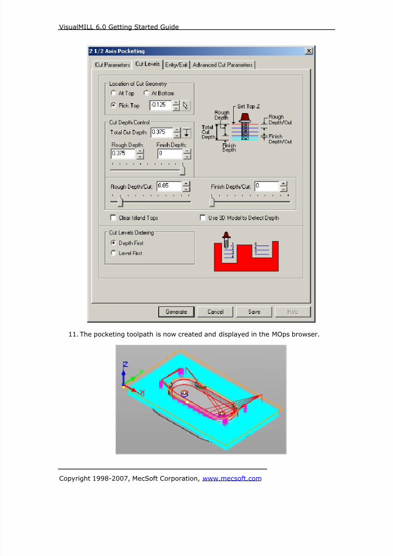
9. Double click under Parameters and switch to the Cut Levels Tab.10. Use the Following Settings.
a. Location of Cut Geometry – Select Pick at Top = – 0.125 b. Total Cut Depth – Set this to 0.375
c. Set the Rough Depth = 0.375 and Rough Depth /Cut = 0.05 d. Switch to the Entry/Exit tab and set the Retract Motion to Linear,
Length = 0.1 and Angle = 0
e. Click Generate.
8/16/2019 Visual Mill Getting Started Guide
http://slidepdf.com/reader/full/visual-mill-getting-started-guide 103/411
VisualMILL 6.0 Getting Started Guide
Copyright 1998-2007, MecSoft Corporation, www.mecsoft.com
11. The pocketing toolpath is now created and displayed in the MOps browser.

8/16/2019 Visual Mill Getting Started Guide
http://slidepdf.com/reader/full/visual-mill-getting-started-guide 104/411
VisualMILL 6.0 Getting Started Guide
Copyright 1998-2007, MecSoft Corporation, www.mecsoft.com
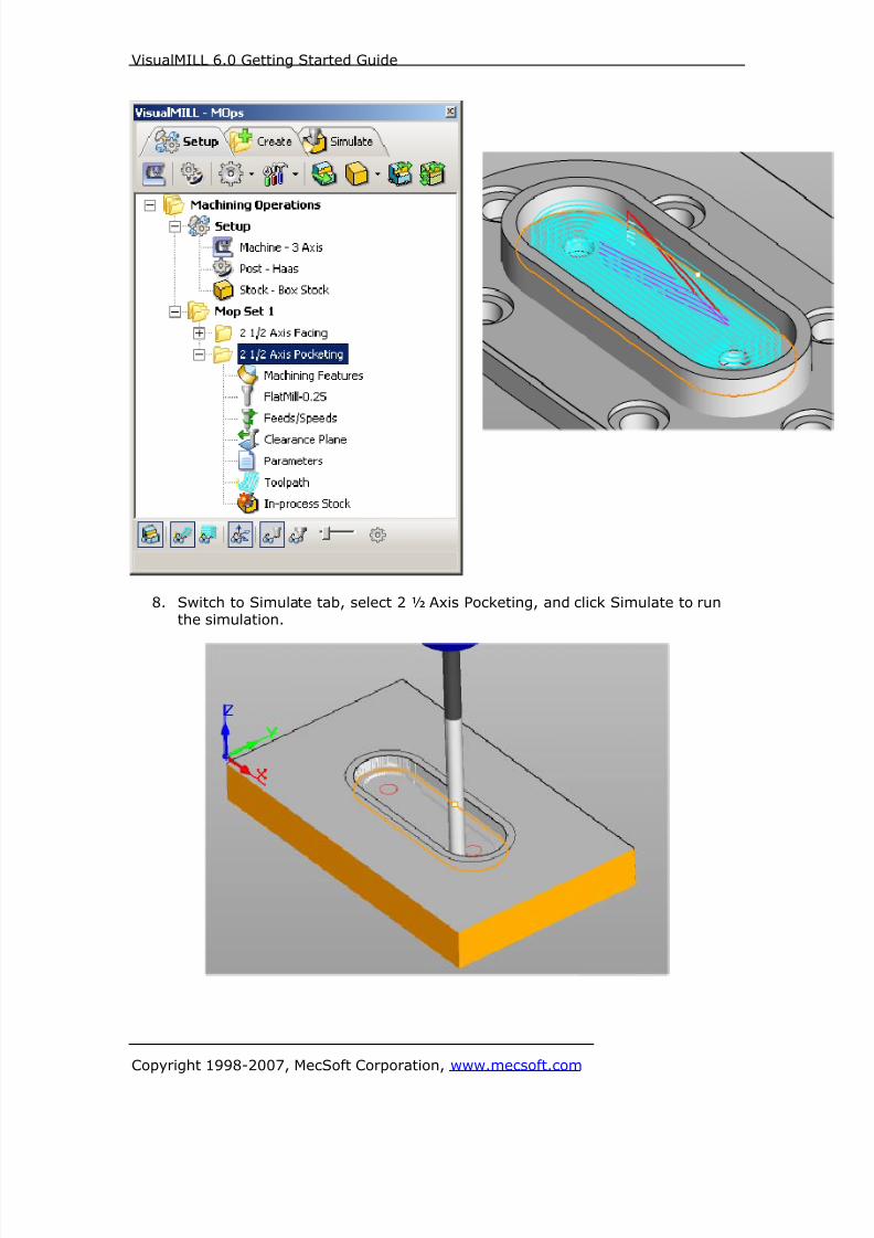
12. Switch to Simulate tab, select 2 ½ Axis Pocketing (1), and click Simulate to
run the simulation.
Note: To turn on/off the toolpath and stock model visibilities use the controls locatedat the bottom of the MOps Browser.
8/16/2019 Visual Mill Getting Started Guide
http://slidepdf.com/reader/full/visual-mill-getting-started-guide 105/411
VisualMILL 6.0 Getting Started Guide
Copyright 1998-2007, MecSoft Corporation, www.mecsoft.com
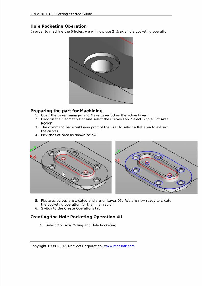
Hole Pocketing Operation
In order to machine the 6 holes, we will now use 2 ½ axis hole pocketing operation.
Preparing the part for Machining1. Open the Layer manager and Make Layer 03 as the active layer.2. Click on the Geometry Bar and select the Curves Tab. Select Single Flat Area
Region.3. The command bar would now prompt the user to select a flat area to extract
the curves4. Pick the flat area as shown below.
5. Flat area curves are created and are on Layer 03. We are now ready to createthe pocketing operation for the inner region.
6. Switch to the Create Operations tab.
Creating the Hole Pocketing Operation #1
1. Select 2 ½ Axis Milling and Hole Pocketing.
8/16/2019 Visual Mill Getting Started Guide
http://slidepdf.com/reader/full/visual-mill-getting-started-guide 106/411
VisualMILL 6.0 Getting Started Guide
Copyright 1998-2007, MecSoft Corporation, www.mecsoft.com
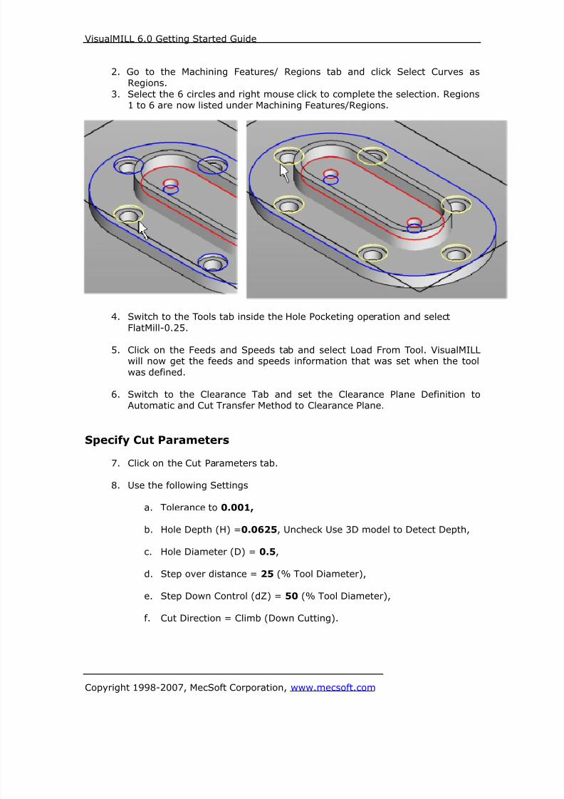
2. Go to the Machining Features/ Regions tab and click Select Curves as
Regions.
3. Select the 6 circles and right mouse click to complete the selection. Regions1 to 6 are now listed under Machining Features/Regions.
4. Switch to the Tools tab inside the Hole Pocketing operation and select
FlatMill-0.25.
5. Click on the Feeds and Speeds tab and select Load From Tool. VisualMILLwill now get the feeds and speeds information that was set when the tool
was defined.
6. Switch to the Clearance Tab and set the Clearance Plane Definition toAutomatic and Cut Transfer Method to Clearance Plane.
Specify Cut Parameters
7. Click on the Cut Parameters tab.
8. Use the following Settings
a. Tolerance to 0.001,
b. Hole Depth (H) =0.0625, Uncheck Use 3D model to Detect Depth,
c. Hole Diameter (D) = 0.5,
d. Step over distance = 25 (% Tool Diameter),
e. Step Down Control (dZ) = 50 (% Tool Diameter),
f. Cut Direction = Climb (Down Cutting).

8/16/2019 Visual Mill Getting Started Guide
http://slidepdf.com/reader/full/visual-mill-getting-started-guide 107/411
VisualMILL 6.0 Getting Started Guide
Copyright 1998-2007, MecSoft Corporation, www.mecsoft.com
9. Switch to the Entry Exit Tab and set the Helix Diameter = 0.25.
8/16/2019 Visual Mill Getting Started Guide
http://slidepdf.com/reader/full/visual-mill-getting-started-guide 108/411
VisualMILL 6.0 Getting Started Guide
Copyright 1998-2007, MecSoft Corporation, www.mecsoft.com
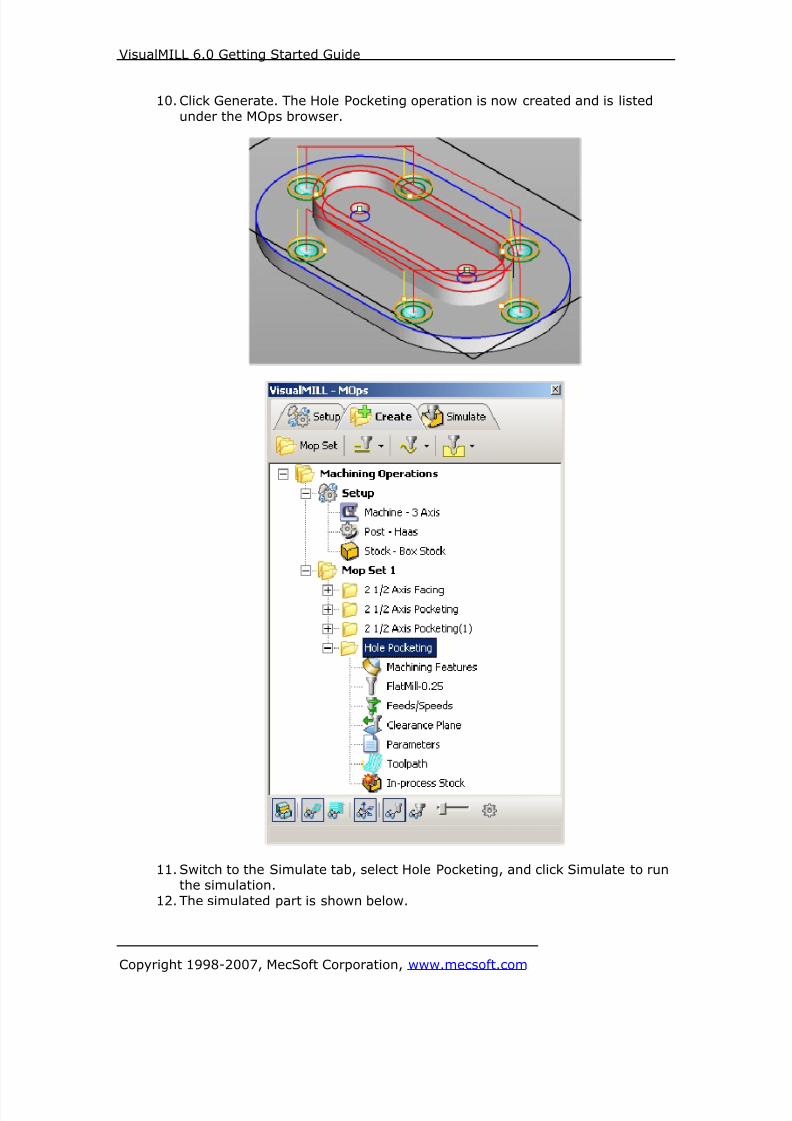
10. Click Generate. The Hole Pocketing operation is now created and is listed
under the MOps browser.
11. Switch to the Simulate tab, select Hole Pocketing, and click Simulate to runthe simulation.
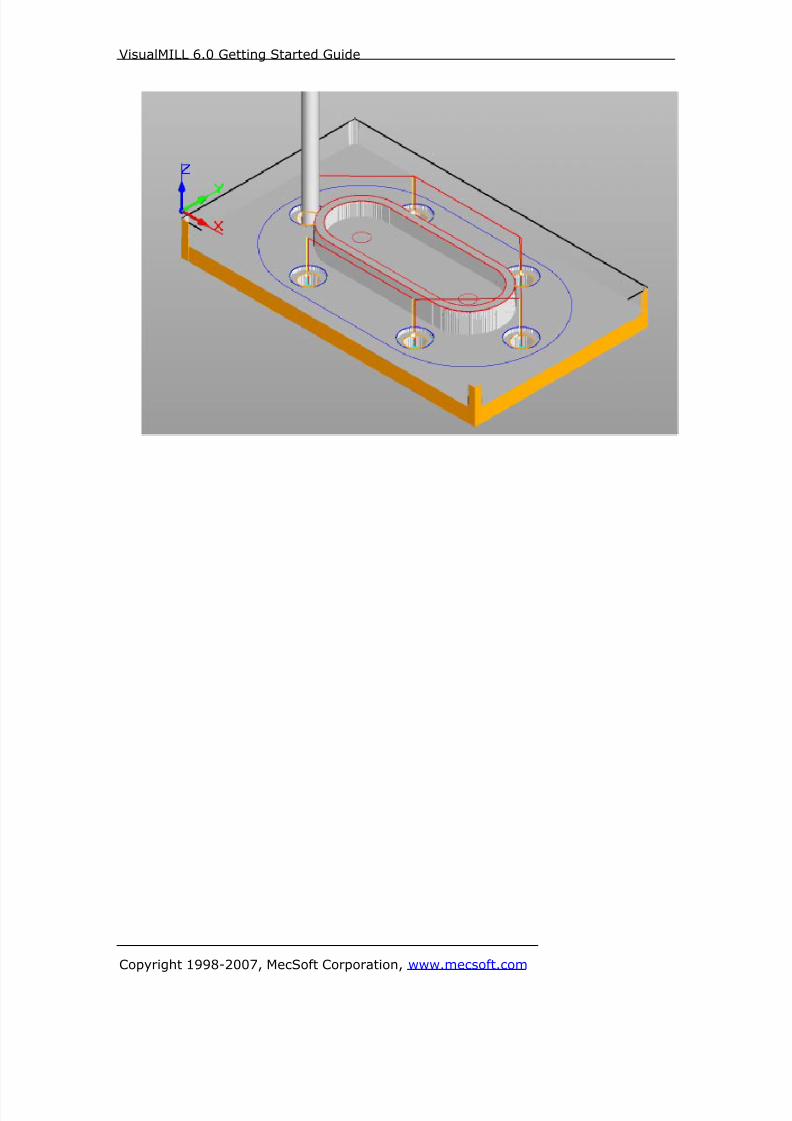
12. The simulated part is shown below.

8/16/2019 Visual Mill Getting Started Guide
http://slidepdf.com/reader/full/visual-mill-getting-started-guide 109/411
VisualMILL 6.0 Getting Started Guide
Copyright 1998-2007, MecSoft Corporation, www.mecsoft.com

8/16/2019 Visual Mill Getting Started Guide
http://slidepdf.com/reader/full/visual-mill-getting-started-guide 110/411
VisualMILL 6.0 Getting Started Guide
Copyright 1998-2007, MecSoft Corporation, www.mecsoft.com
Creating the Hole Pocketing Operation #2
6. Switch to the Create Operations tab.
7. Open Layer Manager and select Layer 04 as the active layer.8. Click on the Geometry Bar and select the Curves Tab. Select Single Flat Area
Region.
9. The command bar would now prompt the user to select a flat area to extractthe curves.
10. Pick the flat area as shown below.
11. Repeat the flat area region for the other 5 holes. The extracted curves are asshown below.
Creating the Hole Pocketing Operation
12. Select the Hole Pocketing Operation created from the previous step, rightmouse click, and select Copy.
13. Right click and select Paste.
14. This would create a copy of the Hole Pocketing Operation listed below the first
Hole Pocketing operation as show below.

8/16/2019 Visual Mill Getting Started Guide
http://slidepdf.com/reader/full/visual-mill-getting-started-guide 111/411
VisualMILL 6.0 Getting Started Guide
Copyright 1998-2007, MecSoft Corporation, www.mecsoft.com
15. Expand the Hole Pocketing (1) folder and double click on Machining Features.
16. Click Remove All under Machining Features and click Select Curves asRegions.
17. Select the 6 inner circles and right mouse click to complete the selection.
18. Regions 1 to 6 are now listed under Machining Features/Regions. Click Saveto Close the Machining Regions Dialog.
19. Double Click under Parameters and set the Hole Depth = 0.1875, Hole
Diameter = 0.315.

8/16/2019 Visual Mill Getting Started Guide
http://slidepdf.com/reader/full/visual-mill-getting-started-guide 112/411
VisualMILL 6.0 Getting Started Guide
Copyright 1998-2007, MecSoft Corporation, www.mecsoft.com
20. Switch to the Entry/Exit tab and set the Helix Diameter to 0.09.
21. Click Generate. The Hole Pocketing Operation for the inner holes is now
created.

8/16/2019 Visual Mill Getting Started Guide
http://slidepdf.com/reader/full/visual-mill-getting-started-guide 113/411
VisualMILL 6.0 Getting Started Guide
Copyright 1998-2007, MecSoft Corporation, www.mecsoft.com
22. Switch to the Simulate tab, select Hole Pocketing(1), and click Simulate to
run the simulation.
8/16/2019 Visual Mill Getting Started Guide
http://slidepdf.com/reader/full/visual-mill-getting-started-guide 114/411
VisualMILL 6.0 Getting Started Guide
Copyright 1998-2007, MecSoft Corporation, www.mecsoft.com

8/16/2019 Visual Mill Getting Started Guide
http://slidepdf.com/reader/full/visual-mill-getting-started-guide 115/411
VisualMILL 6.0 Getting Started Guide
Copyright 1998-2007, MecSoft Corporation, www.mecsoft.com
2 ½ Axis Engraving Operation
Now we will use engraving operation to drill the 2 holes. This can also be
accomplished by using a drilling operation that is available under Hole Machining.
Preparing the part for machiningTurn on the Center Point Snap from the status bar and turn off the other snaps.
1. Click on the Geometry Bar and select the Points Tab. Select Create Point.
2. The command input bar will now prompt the user to pick or enter thecoordinates for the point. We will now use the pick option by creating a point
that snaps to the center of the circle as show below.
3. Repeat the above steps for the other circle.

8/16/2019 Visual Mill Getting Started Guide
http://slidepdf.com/reader/full/visual-mill-getting-started-guide 116/411
VisualMILL 6.0 Getting Started Guide
Copyright 1998-2007, MecSoft Corporation, www.mecsoft.com
Creating the Engraving Toolpath
1. From the Create Operations tab, select 2 ½ Axis Milling and Engraving.
2. Go to the Machining Features/ Regions tab, click Remove All under MachiningFeatures, and click Select Curves as Regions.
3. Select the 2 points as regions for engraving. Right click to complete the
selection.
4. Switch to the Tools tab inside the Engraving operation and select FlatMill-0.25.
5. Click on the Feeds and Speeds tab and select Load From Tool. VisualMILL will
now get the feeds and speeds information that was set when the tool wasdefined.
6. Switch to the Clearance Tab and set the Clearance Plane Definition to
Automatic and Cut Transfer Method to Clearance Plane.7. Switch to the Cut Parameters tab and use the following parameters -
Tolerance = 0.001, Location of Cut Geometry At Top, Total Cut Depth =0.375, Rough Depth = 0.375 and Rough Depth/Cut = 0.05.
8. Set the Entry and Exit to None under the Entry/Exit tab.
9. Click Generate. The Engraving operation is now created.
10. Switch to Simulate tab, select Engraving, and click Simulate to run the
simulation.

8/16/2019 Visual Mill Getting Started Guide
http://slidepdf.com/reader/full/visual-mill-getting-started-guide 117/411
VisualMILL 6.0 Getting Started Guide
Copyright 1998-2007, MecSoft Corporation, www.mecsoft.com

8/16/2019 Visual Mill Getting Started Guide
http://slidepdf.com/reader/full/visual-mill-getting-started-guide 118/411
VisualMILL 6.0 Getting Started Guide
Copyright 1998-2007, MecSoft Corporation, www.mecsoft.com
2 ½ Axis Profiling
1. Switch to the Create Operations tab and select 2.5 Axis Milling and choose
Profiling.2. Go to the Machining Features/ Regions tab, click Remove All under
Machining Features, and click Select Curves as Regions.3. Select the outer curve. Right mouse click or select enter from the keypad to
complete the selection.
4. The selected region is now displayed under Machining Features/Regions.
5. Switch to the Tools tab inside 2 ½ Axis Profiling operation and Select the
FlatMill-0.25.
6. Click on the Feeds and Speeds tab. And select Load From Tool. VisualMILL willnow get the feeds and speeds information that was set when the tool was
defined.7. Switch to Clearance Tab. Set the Clearance Plane Definition to Automatic and
Cut Transfer Method to Clearance Plane.

8/16/2019 Visual Mill Getting Started Guide
http://slidepdf.com/reader/full/visual-mill-getting-started-guide 119/411
VisualMILL 6.0 Getting Started Guide
Copyright 1998-2007, MecSoft Corporation, www.mecsoft.com
Specifying Cut Parameters
8. Switch to Cut Parameters tab and use the following Settings
a. Tolerance = 0.001,
b. Stock = 0,
c. Cut Start Side- Check Use Outside/Inside for closed curves and pick
Outside.
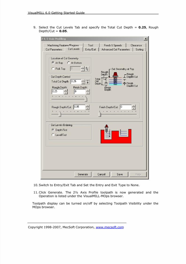
8/16/2019 Visual Mill Getting Started Guide
http://slidepdf.com/reader/full/visual-mill-getting-started-guide 120/411
VisualMILL 6.0 Getting Started Guide
Copyright 1998-2007, MecSoft Corporation, www.mecsoft.com
9. Select the Cut Levels Tab and specify the Total Cut Depth = 0.25, Rough
Depth/Cut = 0.05.
10. Switch to Entry/Exit Tab and Set the Entry and Exit Type to None.
11. Click Generate. The 2½ Axis Profile toolpath is now generated and theOperation is listed under the VisualMILL-MOps browser.
Toolpath display can be turned on/off by selecting Toolpath Visibility under theMOps browser.

8/16/2019 Visual Mill Getting Started Guide
http://slidepdf.com/reader/full/visual-mill-getting-started-guide 121/411
VisualMILL 6.0 Getting Started Guide
Copyright 1998-2007, MecSoft Corporation, www.mecsoft.com
12. Switch to the Simulate tab in the VisualMILL-MOps browser. Select the 2 ½Axis Profiling Operation and click to Simulate.
13. The simulated part is as shown below.
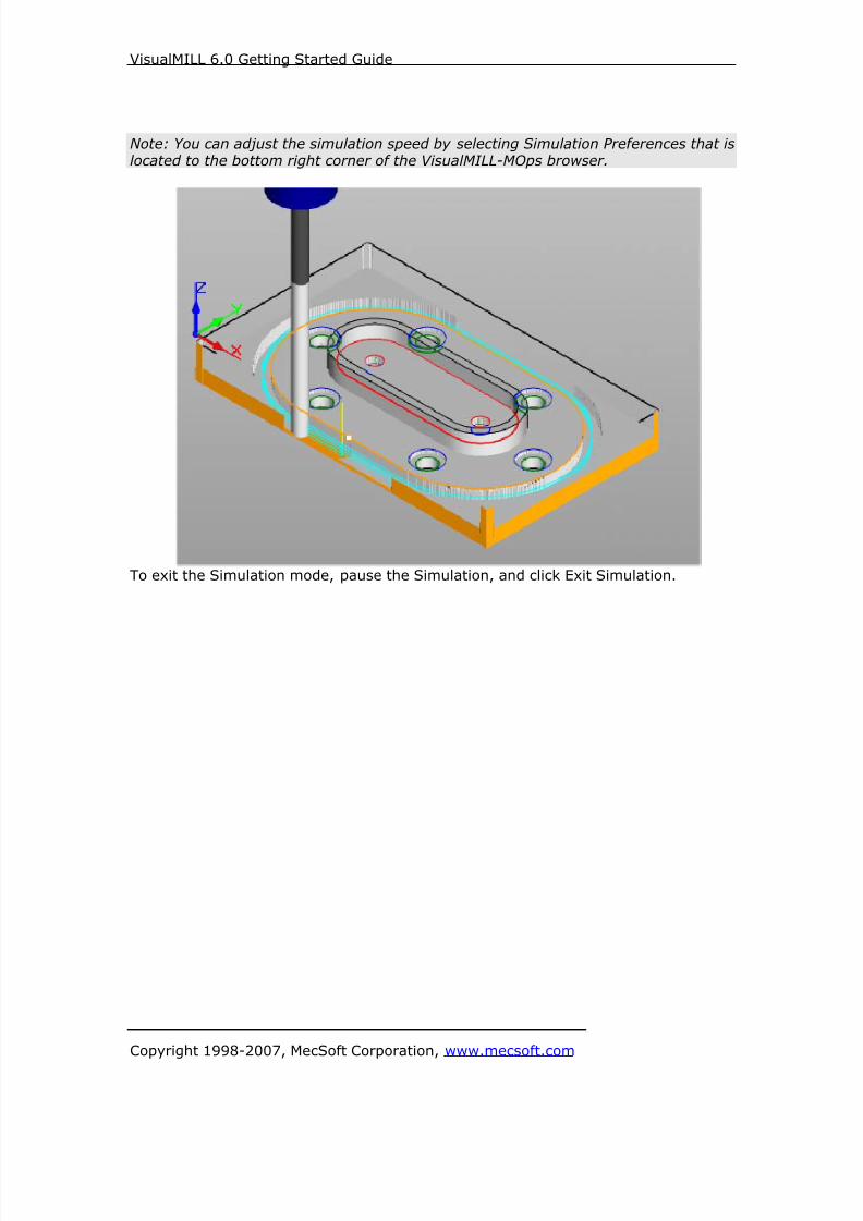
8/16/2019 Visual Mill Getting Started Guide
http://slidepdf.com/reader/full/visual-mill-getting-started-guide 122/411
VisualMILL 6.0 Getting Started Guide
Copyright 1998-2007, MecSoft Corporation, www.mecsoft.com
Note: You can adjust the simulation speed by selecting Simulation Preferences that islocated to the bottom right corner of the VisualMILL-MOps browser.
To exit the Simulation mode, pause the Simulation, and click Exit Simulation.

8/16/2019 Visual Mill Getting Started Guide
http://slidepdf.com/reader/full/visual-mill-getting-started-guide 123/411
VisualMILL 6.0 Getting Started Guide
Copyright 1998-2007, MecSoft Corporation, www.mecsoft.com
Post Processing
1. Select Machining Operations from the Create Operations tab and right click
and select post process.
2. Specify the File Name as Shaftbase.nc and click save.
The post by default is set to Haas as specified under the Post processor setup. You
can change the post processor by selecting a different one from the drop down menu
in the list. The posted g code by default will be saved to the folder where the part fileis located.
End of Tutorial 3!

8/16/2019 Visual Mill Getting Started Guide
http://slidepdf.com/reader/full/visual-mill-getting-started-guide 124/411
VisualMILL 6.0 Getting Started Guide
Copyright 1998-2007, MecSoft Corporation, www.mecsoft.com
Tutorial 4: Simple V-Carving

8/16/2019 Visual Mill Getting Started Guide
http://slidepdf.com/reader/full/visual-mill-getting-started-guide 125/411
VisualMILL 6.0 Getting Started Guide
Copyright 1998-2007, MecSoft Corporation, www.mecsoft.com
Introduction
This tutorial will illustrate machining a Sign using 2-1/2 axis-engraving operations.
We can engrave the sign using 2-D curves. This tutorial will introduce the usage of 2-½ axis simple V Carving using V bit.
V carving refers to a cutting strategy employed by sign makers to create sharp
corners. V carving is performed using a tapered bit or conical tool (as shown below)usually known in the industry as a V Bit.
The V-bit is made to rise from the cutting depth to the top of the surface at thecorners in such a way that the tapered sides of the cutter are always in contact with
the corners. When the cutter finally reaches the top surface, only the bottom tip ofthe tool will be in contact with the corners, thereby creating clean and crisp cuts at
the corners.
The stepped instructions are accompanied by explanatory and introductory text.
Reading this text will help you understand the tutorial methodology and provideinformation about additional options available.
Don’t forget to save your work periodically! You may want to save the file under a
different name so that the original file will be preserved.
Strategy to Machine the part
• V carving is performed using the 2 ½ axis Machining Operation.
• The part itself will be machined out of a 10.75 inch x 4 inch x ½ inch poplarwood sheet
• The part would be machined using a single V-Groove bit.
• The wooden sheet will be held to the machine table or the spoil sheet on thetable using double-sided tape.
Main Programming StepsIn creating programs for each setup, the following steps will be followed:
• Create the Stock geometry
• Set the Machine zero point or Locate geometry with respect to the machine
coordinates
• Create / Select the tool used for machining
• Set the feeds and speeds
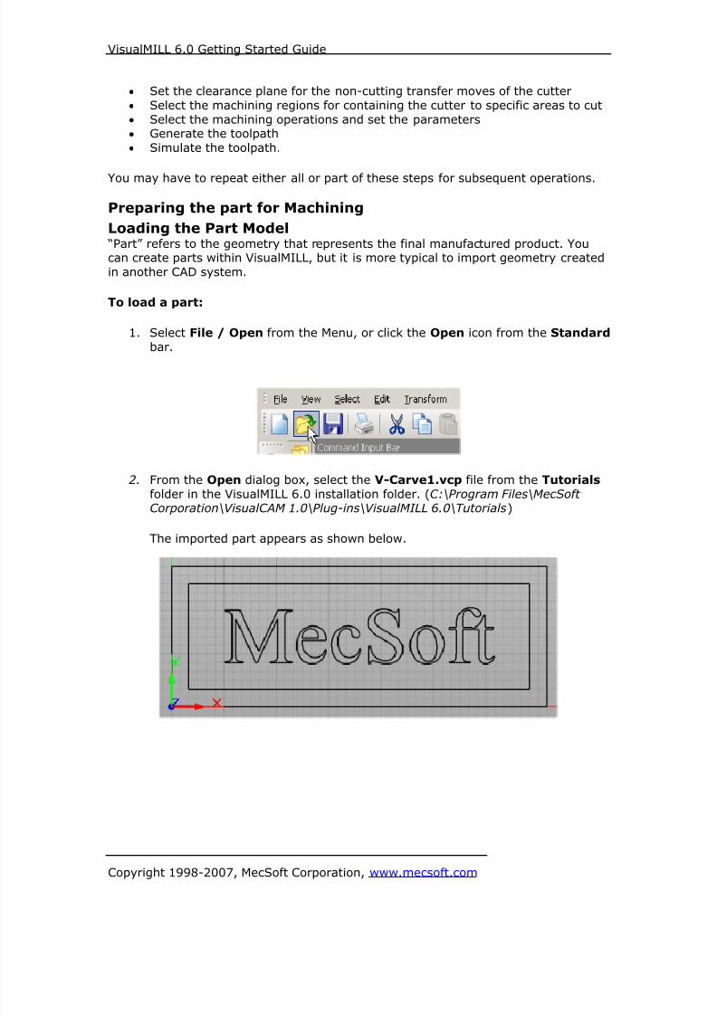
8/16/2019 Visual Mill Getting Started Guide
http://slidepdf.com/reader/full/visual-mill-getting-started-guide 126/411
VisualMILL 6.0 Getting Started Guide
Copyright 1998-2007, MecSoft Corporation, www.mecsoft.com
• Set the clearance plane for the non-cutting transfer moves of the cutter
• Select the machining regions for containing the cutter to specific areas to cut
• Select the machining operations and set the parameters
• Generate the toolpath
• Simulate the toolpath.
You may have to repeat either all or part of these steps for subsequent operations.
Preparing the part for Machining
Loading the Part Model “Part” refers to the geometry that represents the final manufactured product. Youcan create parts within VisualMILL, but it is more typical to import geometry created
in another CAD system.
To load a part:
1. Select File / Open from the Menu, or click the Open icon from the Standard
bar.
2. From the Open dialog box, select the V-Carve1.vcp file from the Tutorials
folder in the VisualMILL 6.0 installation folder. (C:\Program Files\MecSoftCorporation\VisualCAM 1.0\Plug-ins\VisualMILL 6.0\Tutorials)
The imported part appears as shown below.

8/16/2019 Visual Mill Getting Started Guide
http://slidepdf.com/reader/full/visual-mill-getting-started-guide 127/411
VisualMILL 6.0 Getting Started Guide
Copyright 1998-2007, MecSoft Corporation, www.mecsoft.com
Setup Tab
1. Go to the VisualMILL- MOps browser and click on the Setup tab.
2. Select Machine Setup from the setup tab.
3. Set the Machine type to 3 axis.

8/16/2019 Visual Mill Getting Started Guide
http://slidepdf.com/reader/full/visual-mill-getting-started-guide 128/411
VisualMILL 6.0 Getting Started Guide
Copyright 1998-2007, MecSoft Corporation, www.mecsoft.com
4. Select Post from the setup tab to specify the post processor options.
5. Set the current post processor that is on your controller. We will select Haas
as the post processor for this exercise.
Note: By default post processor files are located under
C:\Program Files\MecSoft Corporation\VisualCAM 1.0\Plug-ins\VisualMill 6.0\Posts
The program to send the posted output is set to notepad. This would output the G
code to a notepad.
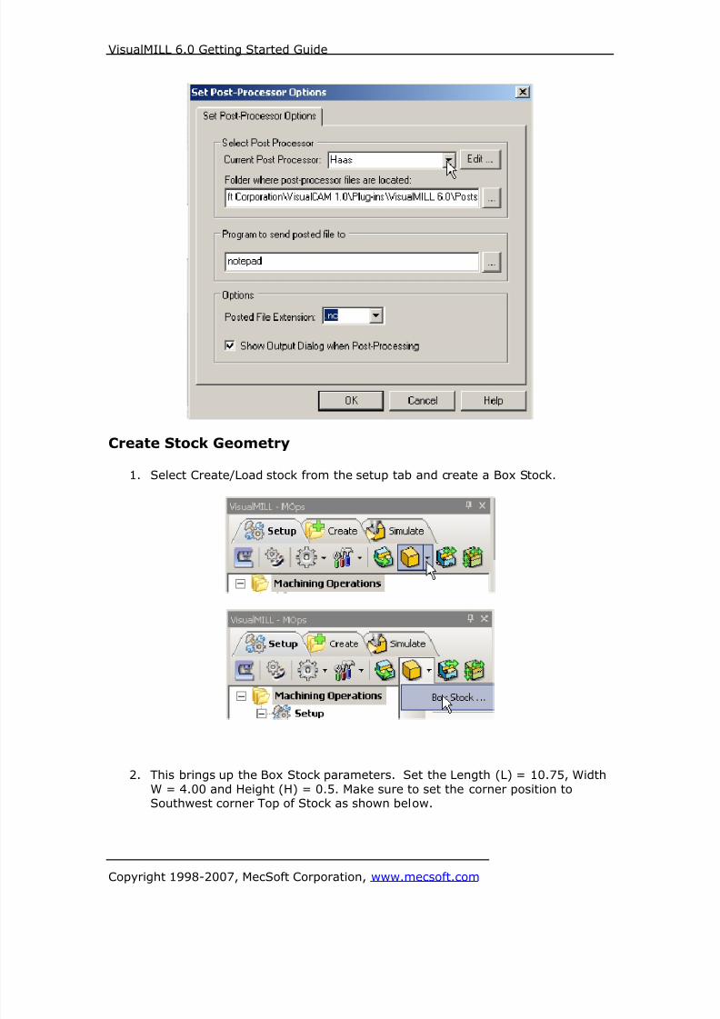
8/16/2019 Visual Mill Getting Started Guide
http://slidepdf.com/reader/full/visual-mill-getting-started-guide 129/411
VisualMILL 6.0 Getting Started Guide
Copyright 1998-2007, MecSoft Corporation, www.mecsoft.com
Create Stock Geometry
1. Select Create/Load stock from the setup tab and create a Box Stock.
2. This brings up the Box Stock parameters. Set the Length (L) = 10.75, Width
W = 4.00 and Height (H) = 0.5. Make sure to set the corner position toSouthwest corner Top of Stock as shown below.

8/16/2019 Visual Mill Getting Started Guide
http://slidepdf.com/reader/full/visual-mill-getting-started-guide 130/411
VisualMILL 6.0 Getting Started Guide
Copyright 1998-2007, MecSoft Corporation, www.mecsoft.com
3. The stock geometry is now created, and a semi-transparent stock box isdisplayed on top of the part geometry.
4. The setup tab now displays the following information: Machine Type, PostProcessor, and Stock type as show below.
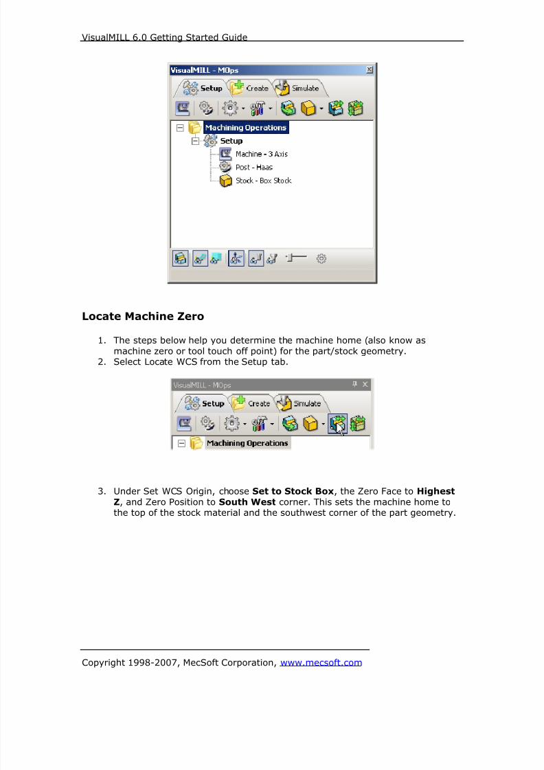
8/16/2019 Visual Mill Getting Started Guide
http://slidepdf.com/reader/full/visual-mill-getting-started-guide 131/411
VisualMILL 6.0 Getting Started Guide
Copyright 1998-2007, MecSoft Corporation, www.mecsoft.com
Locate Machine Zero
1. The steps below help you determine the machine home (also know as
machine zero or tool touch off point) for the part/stock geometry.2. Select Locate WCS from the Setup tab.
3. Under Set WCS Origin, choose Set to Stock Box, the Zero Face to Highest
Z, and Zero Position to South West corner. This sets the machine home tothe top of the stock material and the southwest corner of the part geometry.
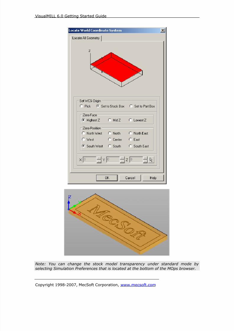
8/16/2019 Visual Mill Getting Started Guide
http://slidepdf.com/reader/full/visual-mill-getting-started-guide 132/411
VisualMILL 6.0 Getting Started Guide
Copyright 1998-2007, MecSoft Corporation, www.mecsoft.com
Note: You can change the stock model transparency under standard mode by
selecting Simulation Preferences that is located at the bottom of the MOps browser.

8/16/2019 Visual Mill Getting Started Guide
http://slidepdf.com/reader/full/visual-mill-getting-started-guide 133/411
VisualMILL 6.0 Getting Started Guide
Copyright 1998-2007, MecSoft Corporation, www.mecsoft.com
Align Part and Stock
In this process, we can align the part and the stock geometry. As we have set the
Machine zero to the Stock Box, we will now move the part relative to the stock.
1. Select Align Part and Stock from the Setup tab.
2. Set to Object to Move as Move Part, Z alignment to Top, and XY alignmentto Center.

8/16/2019 Visual Mill Getting Started Guide
http://slidepdf.com/reader/full/visual-mill-getting-started-guide 134/411
VisualMILL 6.0 Getting Started Guide
Copyright 1998-2007, MecSoft Corporation, www.mecsoft.com
The part geometry is aligned to the center of stock in XY and top in Z. Click Save
to save the work and specify a file name as VCarve-Rev1. The file is now saved
with extension vcp. (VisualCAM Part File)
Note: You can toggle the stock model display by selecting Stock Visibility that islocated at the bottom of the VisualMill-MOps Browser
Create Tools
To machine the above part, we will now create a 60-degree Taper Tool.
1. Go to the VisualMILL-Tools browser that is located below the VisualMILL-MOps
browser and select Create/Edit Tools. Select the Tool Type to VeeMill.
2. Set the tool name as VeeMill1, Taper Angle = 30, Flute Length = 0.4, ToolLength = 2. Under the Properties tab set Tool Number = 1.
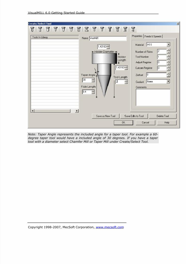
8/16/2019 Visual Mill Getting Started Guide
http://slidepdf.com/reader/full/visual-mill-getting-started-guide 135/411
VisualMILL 6.0 Getting Started Guide
Copyright 1998-2007, MecSoft Corporation, www.mecsoft.com
Note: Taper Angle represents the included angle for a taper tool. For example a 60-
degree taper tool would have a included angle of 30 degrees. If you have a tapertool with a diameter select Chamfer Mill or Taper Mill under Create/Select Tool.

8/16/2019 Visual Mill Getting Started Guide
http://slidepdf.com/reader/full/visual-mill-getting-started-guide 136/411
VisualMILL 6.0 Getting Started Guide
Copyright 1998-2007, MecSoft Corporation, www.mecsoft.com
Setting Feeds and Speeds
You can assign Feeds & Speeds to a tool or you can load from a table. In this
exercise we will assign feeds and speeds to the tool.
3. Switch to the Feeds & Speeds tab inside the create/select tool dialog.
4. Use the following settings for feeds and speeds.
5. Click Save as New Tool. The tool is now created and listed under Tools in
Library. Click OK to close the dialog.
Note: You can edit the tool properties and click Save Edits to Tool to save thechanges. You can create additional tools by assigning a different name and specify
the tool parameters.
The created tools are now listed under the VisualMILL-Tools browser.
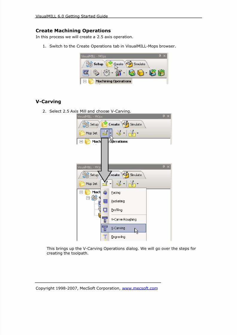
8/16/2019 Visual Mill Getting Started Guide
http://slidepdf.com/reader/full/visual-mill-getting-started-guide 137/411
VisualMILL 6.0 Getting Started Guide
Copyright 1998-2007, MecSoft Corporation, www.mecsoft.com
Create Machining Operations
In this process we will create a 2.5 axis operation.
1. Switch to the Create Operations tab in VisualMILL-Mops browser.
V-Carving
2. Select 2.5 Axis Mill and choose V-Carving.
This brings up the V-Carving Operations dialog. We will go over the steps forcreating the toolpath.

8/16/2019 Visual Mill Getting Started Guide
http://slidepdf.com/reader/full/visual-mill-getting-started-guide 138/411
VisualMILL 6.0 Getting Started Guide
Copyright 1998-2007, MecSoft Corporation, www.mecsoft.com
Select Machining Features/Regions3. Go to the Machining Features/ Regions tab and click Select Curves as
Regions.
4. Now, select the text by using the left mouse click, starting from left to right.Make sure to get the inner curves on the letters ‘e’ and ‘o’. Each curve is
separate (by curves, not by letters) and must be selected separately.
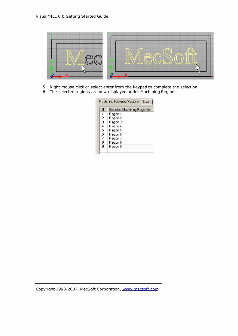
8/16/2019 Visual Mill Getting Started Guide
http://slidepdf.com/reader/full/visual-mill-getting-started-guide 139/411
VisualMILL 6.0 Getting Started Guide
Copyright 1998-2007, MecSoft Corporation, www.mecsoft.com
5. Right mouse click or select enter from the keypad to complete the selection.
6. The selected regions are now displayed under Machining Regions.
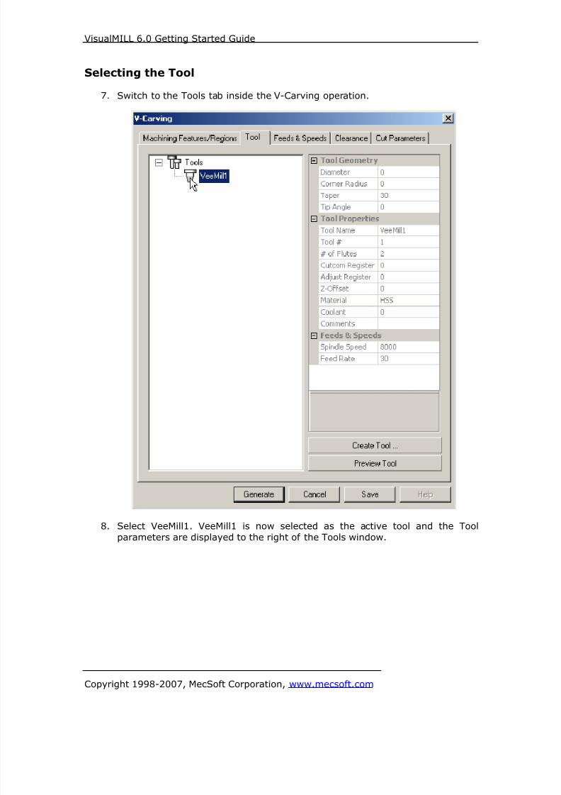
8/16/2019 Visual Mill Getting Started Guide
http://slidepdf.com/reader/full/visual-mill-getting-started-guide 140/411
VisualMILL 6.0 Getting Started Guide
Copyright 1998-2007, MecSoft Corporation, www.mecsoft.com
Selecting the Tool
7. Switch to the Tools tab inside the V-Carving operation.
8. Select VeeMill1. VeeMill1 is now selected as the active tool and the Tool
parameters are displayed to the right of the Tools window.

8/16/2019 Visual Mill Getting Started Guide
http://slidepdf.com/reader/full/visual-mill-getting-started-guide 141/411
VisualMILL 6.0 Getting Started Guide
Copyright 1998-2007, MecSoft Corporation, www.mecsoft.com
Set Feeds and Speeds9. Click on the Feeds and Speeds tab.
10. Select Load From Tool. VisualMILL will now get the feeds and speeds
information that was set when the tool was defined.

8/16/2019 Visual Mill Getting Started Guide
http://slidepdf.com/reader/full/visual-mill-getting-started-guide 142/411
VisualMILL 6.0 Getting Started Guide
Copyright 1998-2007, MecSoft Corporation, www.mecsoft.com
Clearance Control11. Switch to Clearance Tab.
12. Set the Clearance Plane Definition to Absolute Z Value = 0.25 and CutTransfer Method to Clearance Plane.
Setting Cut Transfer to Clearance Plane would apply the Absolute Z value
clearance between transfers when the tool moves from a machining region toanother.
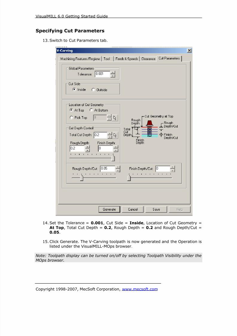
8/16/2019 Visual Mill Getting Started Guide
http://slidepdf.com/reader/full/visual-mill-getting-started-guide 143/411
VisualMILL 6.0 Getting Started Guide
Copyright 1998-2007, MecSoft Corporation, www.mecsoft.com
Specifying Cut Parameters
13. Switch to Cut Parameters tab.
14. Set the Tolerance = 0.001, Cut Side = Inside, Location of Cut Geometry =
At Top, Total Cut Depth = 0.2, Rough Depth = 0.2 and Rough Depth/Cut =0.05.
15. Click Generate. The V-Carving toolpath is now generated and the Operation is
listed under the VisualMILL-MOps browser.
Note: Toolpath display can be turned on/off by selecting Toolpath Visibility under theMOps browser.

8/16/2019 Visual Mill Getting Started Guide
http://slidepdf.com/reader/full/visual-mill-getting-started-guide 144/411
VisualMILL 6.0 Getting Started Guide
Copyright 1998-2007, MecSoft Corporation, www.mecsoft.com
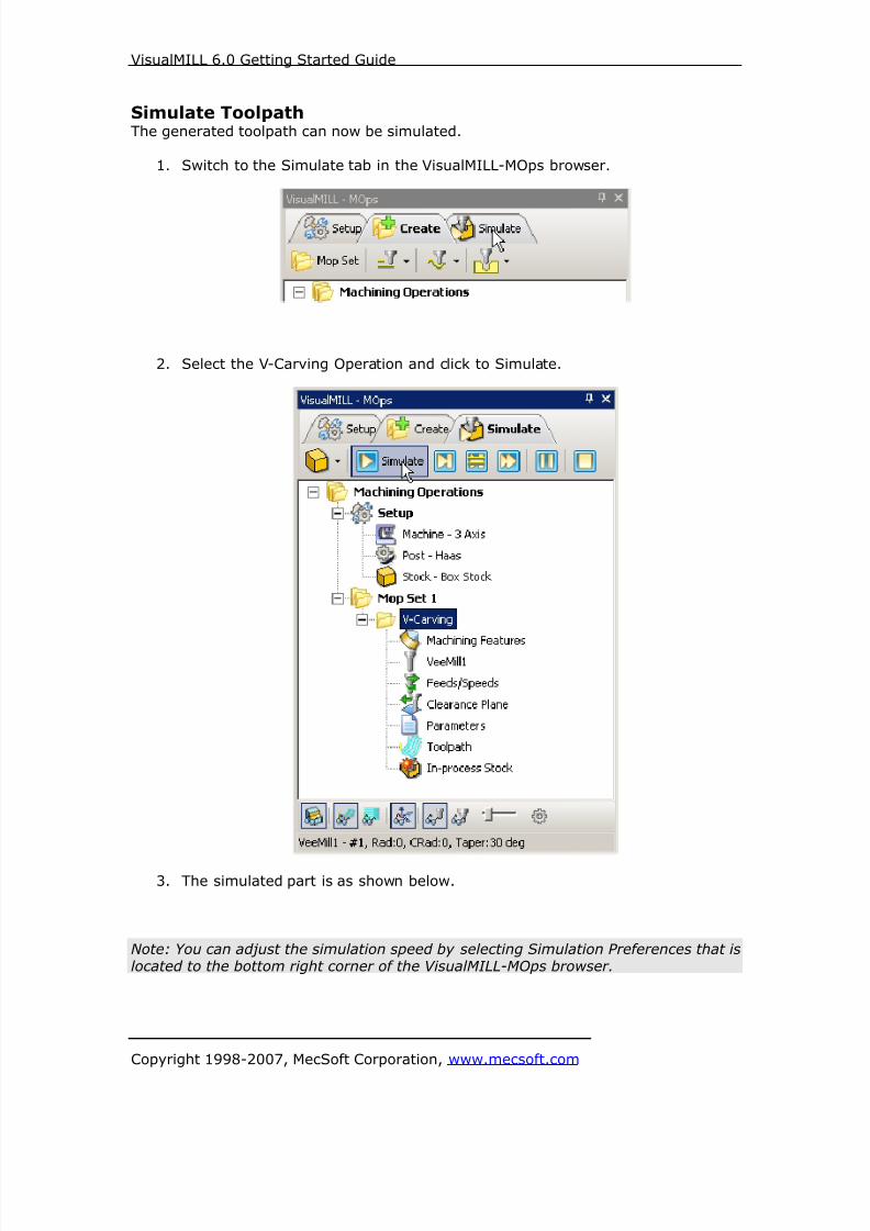
8/16/2019 Visual Mill Getting Started Guide
http://slidepdf.com/reader/full/visual-mill-getting-started-guide 145/411
VisualMILL 6.0 Getting Started Guide
Copyright 1998-2007, MecSoft Corporation, www.mecsoft.com
Simulate ToolpathThe generated toolpath can now be simulated.
1. Switch to the Simulate tab in the VisualMILL-MOps browser.
2. Select the V-Carving Operation and click to Simulate.
3. The simulated part is as shown below.
Note: You can adjust the simulation speed by selecting Simulation Preferences that islocated to the bottom right corner of the VisualMILL-MOps browser.

8/16/2019 Visual Mill Getting Started Guide
http://slidepdf.com/reader/full/visual-mill-getting-started-guide 146/411
VisualMILL 6.0 Getting Started Guide
Copyright 1998-2007, MecSoft Corporation, www.mecsoft.com
To exit the Simulation mode, pause the Simulation, and click Exit Simulation. Thisswitches back to the Create Operations tab.
Post Processing
1. Select Machining Operations from the Create Operations tab and right clickand select post process.
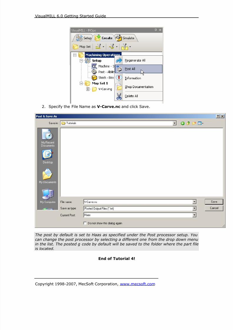
8/16/2019 Visual Mill Getting Started Guide
http://slidepdf.com/reader/full/visual-mill-getting-started-guide 147/411
VisualMILL 6.0 Getting Started Guide
Copyright 1998-2007, MecSoft Corporation, www.mecsoft.com
2. Specify the File Name as V-Carve.nc and click Save.
The post by default is set to Haas as specified under the Post processor setup. You
can change the post processor by selecting a different one from the drop down menuin the list. The posted g code by default will be saved to the folder where the part file
is located.
End of Tutorial 4!
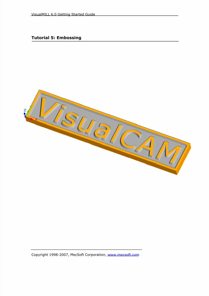
8/16/2019 Visual Mill Getting Started Guide
http://slidepdf.com/reader/full/visual-mill-getting-started-guide 148/411
VisualMILL 6.0 Getting Started Guide
Copyright 1998-2007, MecSoft Corporation, www.mecsoft.com
Tutorial 5: Embossing

8/16/2019 Visual Mill Getting Started Guide
http://slidepdf.com/reader/full/visual-mill-getting-started-guide 149/411
VisualMILL 6.0 Getting Started Guide
Copyright 1998-2007, MecSoft Corporation, www.mecsoft.com
Introduction
This tutorial will illustrate machining a Sign using 2-1/2 axis-engraving operations.
We can engrave the sign using 2-D curves. This tutorial will introduce the usage of 2-½ axis V Carve Roughing with a Flat End Mill and V Carving using V bit.
V carving refers to a cutting strategy employed by sign makers to create sharp
corners. V carving is performed using a tapered bit or conical tool (as shown below)usually known in the industry as a V Bit.
The V-bit is made to rise from the cutting depth to the top of the surface at thecorners in such a way that the tapered sides of the cutter are always in contact with
the corners. When the cutter finally reaches the top surface, only the bottom tip ofthe tool will be in contact with the corners, thereby creating clean and crisp cuts at
the corners.
The stepped instructions are accompanied by explanatory and introductory text.
Reading this text will help you understand the tutorial methodology and provideinformation about additional options available.
Don’t forget to save your work periodically! You may want to save the file under a
different name so that the original file will be preserved.
Strategy to Machine the part
• Embossing is performed using the 2 ½ axis Machining Operations.
• The part itself will be machined out of a 20 inch x 4 inch x 1 inch poplar woodsheet
• The part would be machined using a Flat End Mill and a V-Groove bit.
• The wooden sheet will be held to the machine table or the spoil sheet on thetable using double-sided tape.
Main Programming StepsIn creating programs for each setup, the following steps will be followed:
• Create the Part
• Create the Stock geometry
• Set the Machine zero point or Locate geometry with respect to the machinecoordinates
• Create / Select the tool used for machining

8/16/2019 Visual Mill Getting Started Guide
http://slidepdf.com/reader/full/visual-mill-getting-started-guide 150/411
VisualMILL 6.0 Getting Started Guide
Copyright 1998-2007, MecSoft Corporation, www.mecsoft.com
• Set the feeds and speeds
• Set the clearance plane for the non-cutting transfer moves of the cutter
• Select the machining regions for containing the cutter to specific areas to cut
• Select the machining operations and set the parameters
• Generate the toolpath
• Simulate the toolpath.
You may have to repeat either all or part of these steps for subsequent operations.
Preparing the part for Machining
Creating the Part Model “Part” refers to the geometry that represents the final manufactured product.
To create a part:
1. Select File / New from the Menu, or click the New icon from the Standard
bar. This creates a new session of VisualCAM.
2. Switch to the Top View by double clicking on the Top View under theViewport.
3. Create a rectangle by selecting the Create Rectangle tool that is located onthe Geometry Bar under Lines.
4. Under the Command bar, specify the First Corner as 0,0.
5. Specify the Second Corner as 20,4.
6. Create a 2nd rectangle with the First Corner as 0.25,0.25 and Second Corner
as 19.75,3.75.
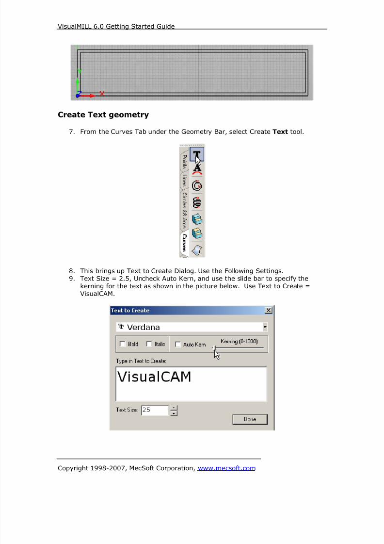
8/16/2019 Visual Mill Getting Started Guide
http://slidepdf.com/reader/full/visual-mill-getting-started-guide 151/411
VisualMILL 6.0 Getting Started Guide
Copyright 1998-2007, MecSoft Corporation, www.mecsoft.com
Create Text geometry
7. From the Curves Tab under the Geometry Bar, select Create Text tool.
8. This brings up Text to Create Dialog. Use the Following Settings.
9. Text Size = 2.5, Uncheck Auto Kern, and use the slide bar to specify the
kerning for the text as shown in the picture below. Use Text to Create =VisualCAM.
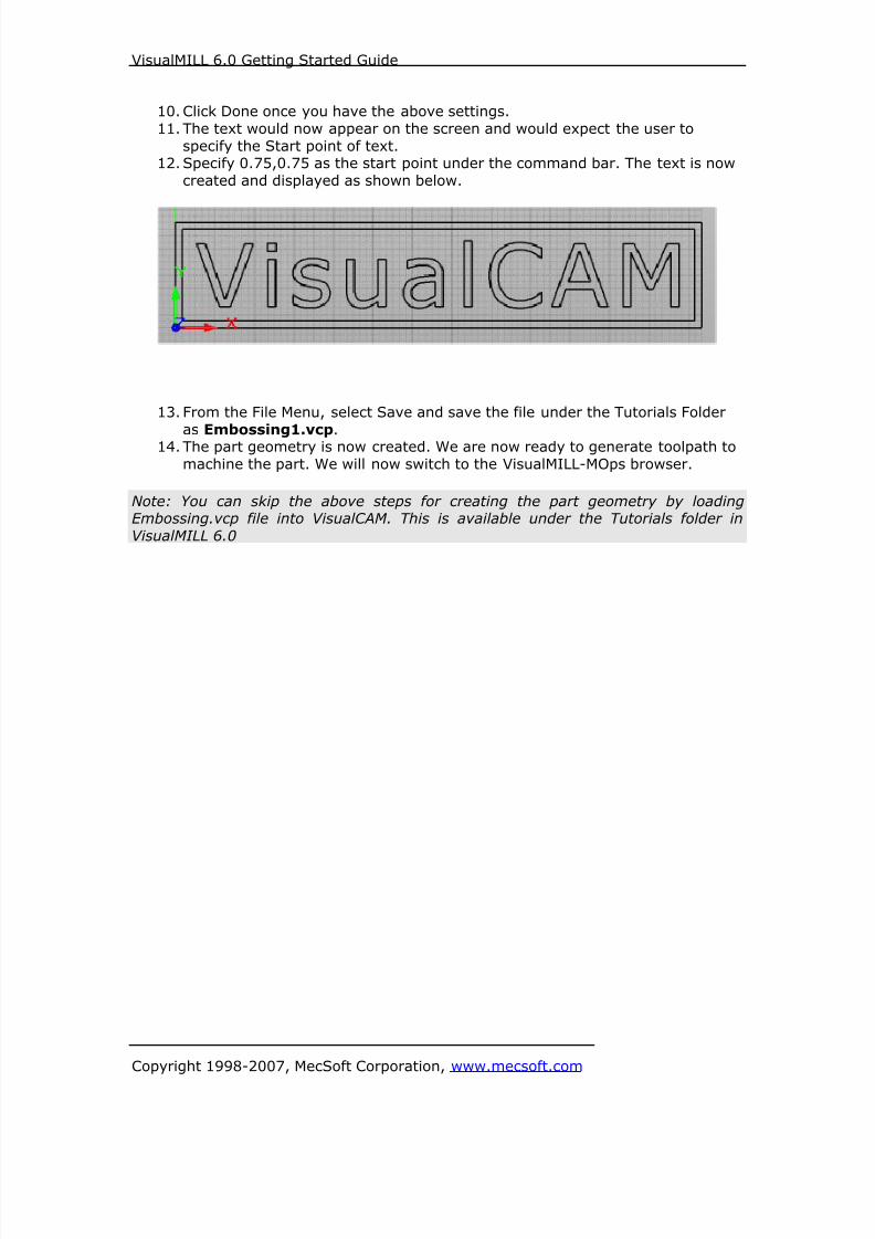
8/16/2019 Visual Mill Getting Started Guide
http://slidepdf.com/reader/full/visual-mill-getting-started-guide 152/411
VisualMILL 6.0 Getting Started Guide
Copyright 1998-2007, MecSoft Corporation, www.mecsoft.com
10. Click Done once you have the above settings.
11. The text would now appear on the screen and would expect the user to
specify the Start point of text.12. Specify 0.75,0.75 as the start point under the command bar. The text is now
created and displayed as shown below.
13. From the File Menu, select Save and save the file under the Tutorials Folder
as Embossing1.vcp.14. The part geometry is now created. We are now ready to generate toolpath to
machine the part. We will now switch to the VisualMILL-MOps browser.
Note: You can skip the above steps for creating the part geometry by loadingEmbossing.vcp file into VisualCAM. This is available under the Tutorials folder in
VisualMILL 6.0
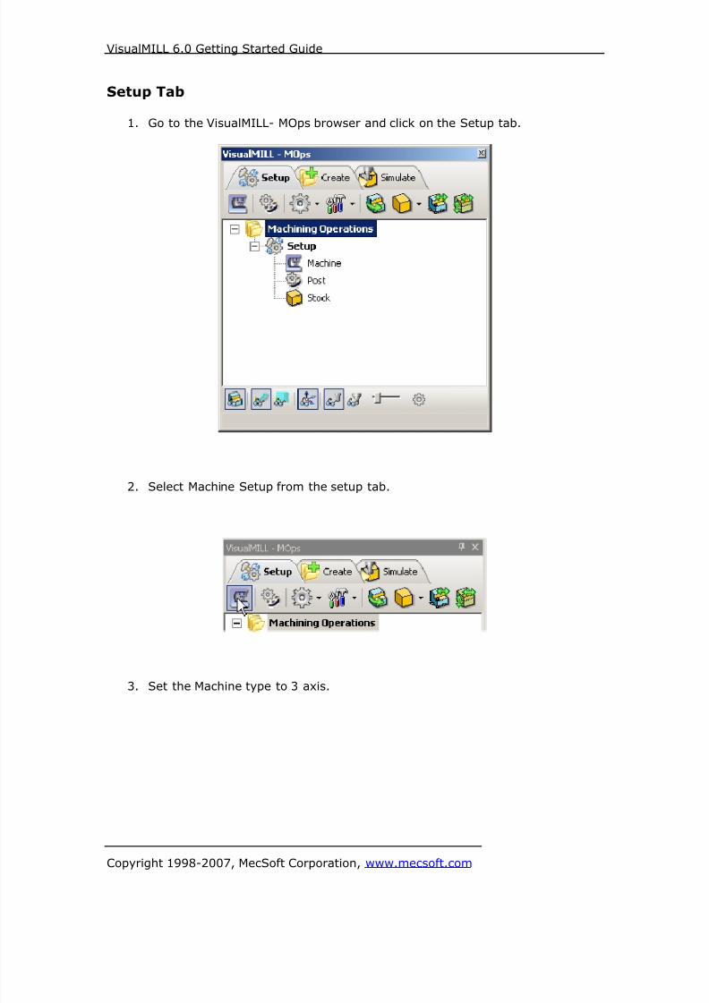
8/16/2019 Visual Mill Getting Started Guide
http://slidepdf.com/reader/full/visual-mill-getting-started-guide 153/411
VisualMILL 6.0 Getting Started Guide
Copyright 1998-2007, MecSoft Corporation, www.mecsoft.com
Setup Tab
1. Go to the VisualMILL- MOps browser and click on the Setup tab.
2. Select Machine Setup from the setup tab.
3. Set the Machine type to 3 axis.

8/16/2019 Visual Mill Getting Started Guide
http://slidepdf.com/reader/full/visual-mill-getting-started-guide 154/411
VisualMILL 6.0 Getting Started Guide
Copyright 1998-2007, MecSoft Corporation, www.mecsoft.com
4. Select Post from the setup tab to specify the post processor options.
5. Set the current post processor that is on your controller. We will select Haasas the post processor for this exercise.
Note: By default post processor files are located under
C:\Program Files\MecSoft Corporation\VisualCAM 1.0\Plug-ins\VisualMill 6.0\Posts
The program to send the posted output is set to notepad. This would output the G
code to a notepad.
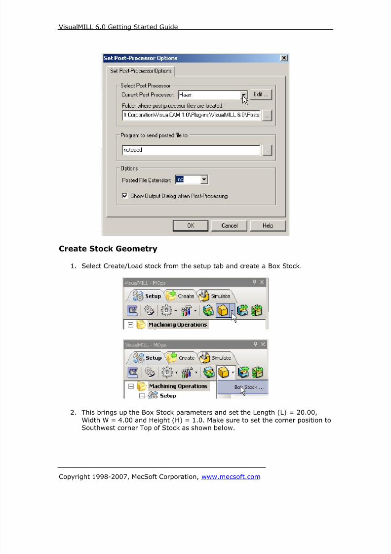
8/16/2019 Visual Mill Getting Started Guide
http://slidepdf.com/reader/full/visual-mill-getting-started-guide 155/411
VisualMILL 6.0 Getting Started Guide
Copyright 1998-2007, MecSoft Corporation, www.mecsoft.com
Create Stock Geometry
1. Select Create/Load stock from the setup tab and create a Box Stock.
2. This brings up the Box Stock parameters and set the Length (L) = 20.00,
Width W = 4.00 and Height (H) = 1.0. Make sure to set the corner position toSouthwest corner Top of Stock as shown below.
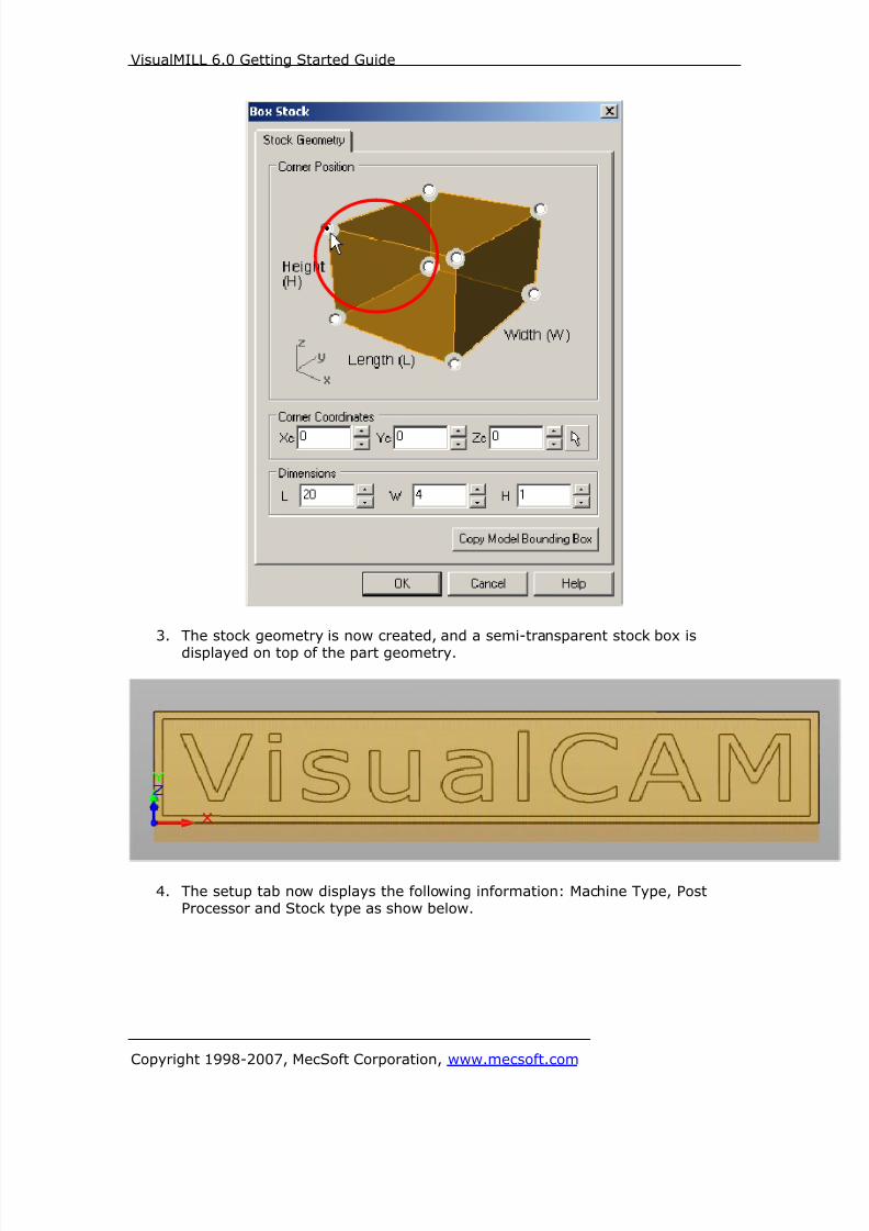
8/16/2019 Visual Mill Getting Started Guide
http://slidepdf.com/reader/full/visual-mill-getting-started-guide 156/411
VisualMILL 6.0 Getting Started Guide
Copyright 1998-2007, MecSoft Corporation, www.mecsoft.com
3. The stock geometry is now created, and a semi-transparent stock box is
displayed on top of the part geometry.
4. The setup tab now displays the following information: Machine Type, PostProcessor and Stock type as show below.

8/16/2019 Visual Mill Getting Started Guide
http://slidepdf.com/reader/full/visual-mill-getting-started-guide 157/411
VisualMILL 6.0 Getting Started Guide
Copyright 1998-2007, MecSoft Corporation, www.mecsoft.com
Locate Machine Zero
1. The steps below help you determine the machine home (also know as
machine zero or tool touch off point) for the part/stock geometry.2. Select Locate WCS from the Setup tab.
3. Under Set WCS Origin, choose Set to Stock Box, the Zero Face to Highest Z
and Zero Position to South West corner. This sets the machine home to thetop of the stock material and the southwest corner of the part geometry.
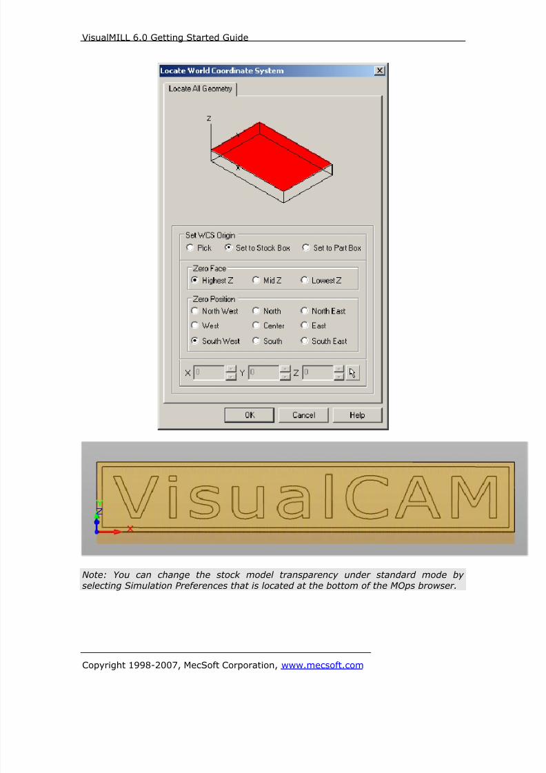
8/16/2019 Visual Mill Getting Started Guide
http://slidepdf.com/reader/full/visual-mill-getting-started-guide 158/411

8/16/2019 Visual Mill Getting Started Guide
http://slidepdf.com/reader/full/visual-mill-getting-started-guide 159/411
VisualMILL 6.0 Getting Started Guide
Copyright 1998-2007, MecSoft Corporation, www.mecsoft.com
Align Part and Stock
In this process, we can align the part and the stock geometry. As we have set the
Machine zero to the Stock Box, we will now move the part relative to the stock.
1. Select Align Part and Stock from the Setup tab.
2. Set to Object to Move as Move Part, Z alignment to Top, and XY alignmentto Center.

8/16/2019 Visual Mill Getting Started Guide
http://slidepdf.com/reader/full/visual-mill-getting-started-guide 160/411
VisualMILL 6.0 Getting Started Guide
Copyright 1998-2007, MecSoft Corporation, www.mecsoft.com
The part geometry is aligned to the center of stock in XY and top in Z. Click Save
to save the work and specify a file name as Embossing-Rev1. The file is now
saved with extension vcp. (VisualCAM Part File)
Note: You can toggle the stock model display by selecting Stock Visibility that islocated at the bottom of the VisualMill-MOps Browser
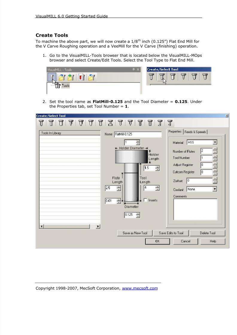
8/16/2019 Visual Mill Getting Started Guide
http://slidepdf.com/reader/full/visual-mill-getting-started-guide 161/411
VisualMILL 6.0 Getting Started Guide
Copyright 1998-2007, MecSoft Corporation, www.mecsoft.com
Create Tools
To machine the above part, we will now create a 1/8th inch (0.125”) Flat End Mill for
the V Carve Roughing operation and a VeeMill for the V Carve (finishing) operation.
1. Go to the VisualMILL-Tools browser that is located below the VisualMILL-MOps
browser and select Create/Edit Tools. Select the Tool Type to Flat End Mill.
2. Set the tool name as FlatMill-0.125 and the Tool Diameter = 0.125. Under
the Properties tab, set Tool Number = 1.

8/16/2019 Visual Mill Getting Started Guide
http://slidepdf.com/reader/full/visual-mill-getting-started-guide 162/411
VisualMILL 6.0 Getting Started Guide
Copyright 1998-2007, MecSoft Corporation, www.mecsoft.com
Setting Feeds and Speeds
You can assign Feeds & Speeds to a tool or you can load from a table. In this
exercise, we will assign feeds and speeds to the tool.
3. Switch to the Feeds & Speeds tab inside the create/select tool dialog.
4. Use the following settings for feeds and speeds.
5. Click Save as New Tool. The tool is now created and listed under Tools inLibrary. Click OK to close the dialog.
Note: You can edit the tool properties and click Save Edits to Tool to save the
changes. You can create additional tools by assigning a different name and specifythe tool parameters.
The created tools are now listed under the VisualMILL-Tools browser.

8/16/2019 Visual Mill Getting Started Guide
http://slidepdf.com/reader/full/visual-mill-getting-started-guide 163/411
VisualMILL 6.0 Getting Started Guide
Copyright 1998-2007, MecSoft Corporation, www.mecsoft.com
6. Create a 2nd tool of type VeeMill.
7. Set the tool name as VeeMill1, Taper Angle = 30, Flute Length = 0.4, and
Tool Length = 2. Under the Properties tab, set Tool Number = 2.
Note: Taper Angle represents the included angle for a taper tool. For example a 60-
degree taper tool would have a included angle of 30 degrees. If you have a tapertool with a diameter select Chamfer Mill or Taper Mill under Create/Select Tool.

8/16/2019 Visual Mill Getting Started Guide
http://slidepdf.com/reader/full/visual-mill-getting-started-guide 164/411
VisualMILL 6.0 Getting Started Guide
Copyright 1998-2007, MecSoft Corporation, www.mecsoft.com
8. Switch to the Feeds & Speeds tab inside the create/select tool dialog and use
the following settings for Feeds/Speeds for the VeeMill1.
9. Click Save as New Tool. The tool is now created and listed under Tools in
Library. Click OK to close the dialog.

8/16/2019 Visual Mill Getting Started Guide
http://slidepdf.com/reader/full/visual-mill-getting-started-guide 165/411
VisualMILL 6.0 Getting Started Guide
Copyright 1998-2007, MecSoft Corporation, www.mecsoft.com
Create Machining Operations
In this process, we will create two 2 ½ axis-machining operations.
1. Switch to the Create Operations tab in VisualMILL-Mops browser.
V-Carving Roughing
2. Select 2.5 Axis Mill and choose V-Carve Roughing.
This brings up the V-Carve Roughing dialog. We will go over the steps forcreating the toolpath.
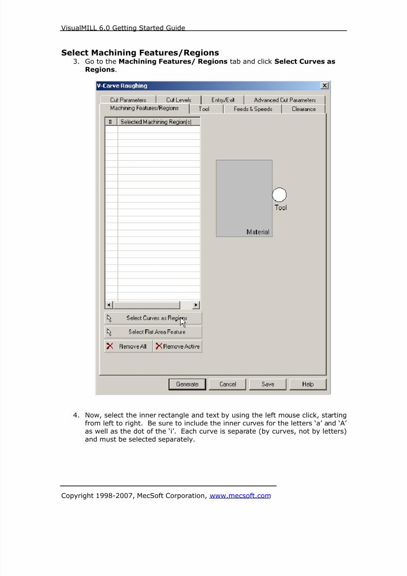
8/16/2019 Visual Mill Getting Started Guide
http://slidepdf.com/reader/full/visual-mill-getting-started-guide 166/411
VisualMILL 6.0 Getting Started Guide
Copyright 1998-2007, MecSoft Corporation, www.mecsoft.com
Select Machining Features/Regions3. Go to the Machining Features/ Regions tab and click Select Curves as
Regions.
4. Now, select the inner rectangle and text by using the left mouse click, starting
from left to right. Be sure to include the inner curves for the letters ‘a’ and ‘A’as well as the dot of the ‘i’. Each curve is separate (by curves, not by letters)
and must be selected separately.
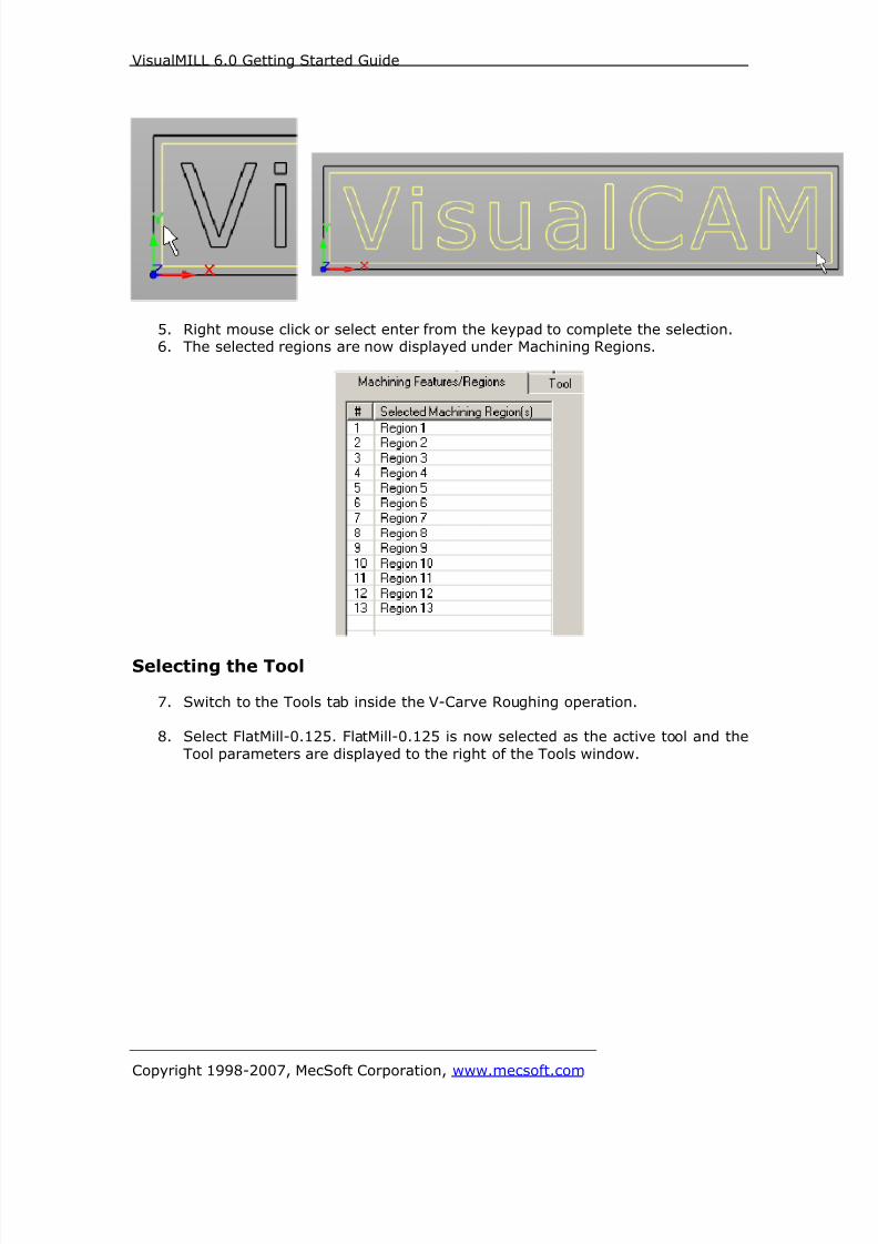
8/16/2019 Visual Mill Getting Started Guide
http://slidepdf.com/reader/full/visual-mill-getting-started-guide 167/411
VisualMILL 6.0 Getting Started Guide
Copyright 1998-2007, MecSoft Corporation, www.mecsoft.com
5. Right mouse click or select enter from the keypad to complete the selection.6. The selected regions are now displayed under Machining Regions.
Selecting the Tool
7. Switch to the Tools tab inside the V-Carve Roughing operation.
8. Select FlatMill-0.125. FlatMill-0.125 is now selected as the active tool and the
Tool parameters are displayed to the right of the Tools window.
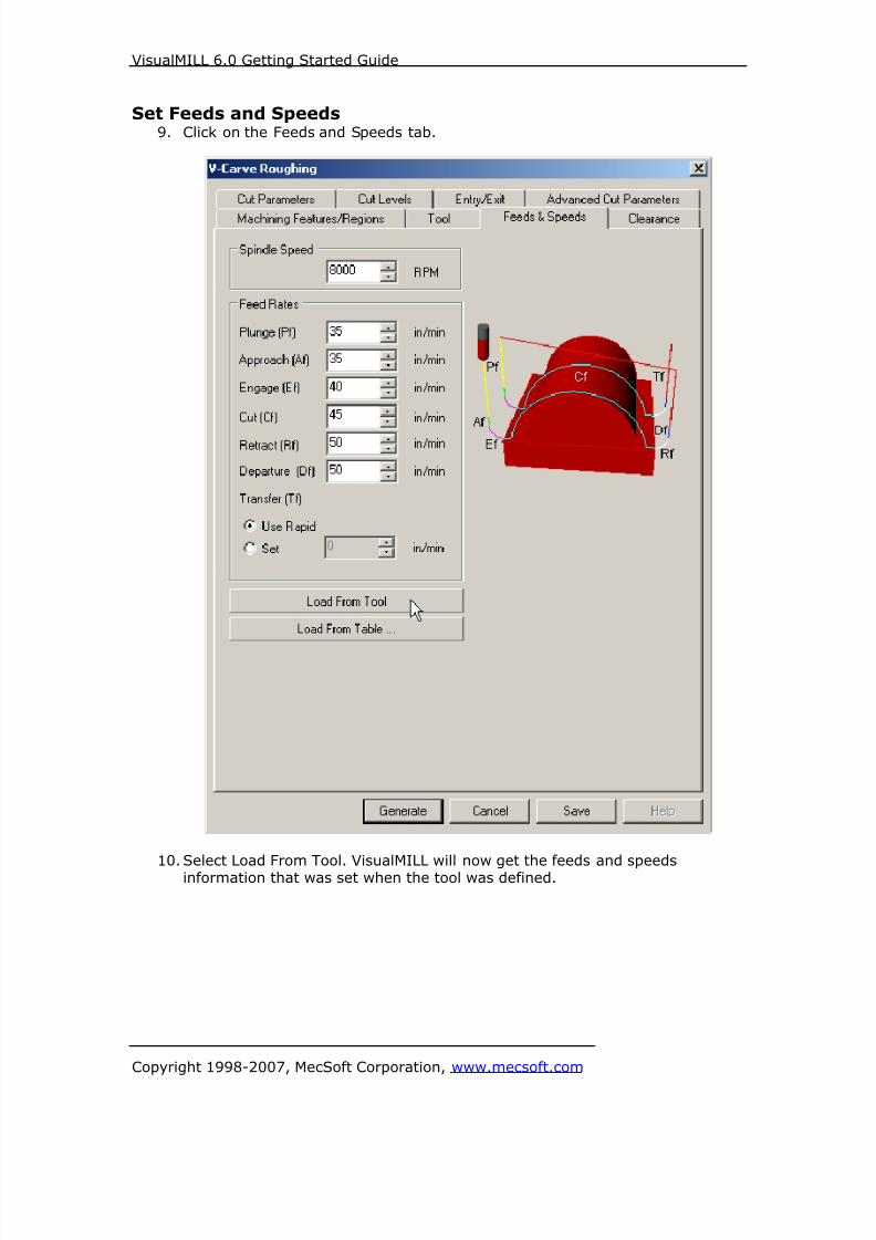
8/16/2019 Visual Mill Getting Started Guide
http://slidepdf.com/reader/full/visual-mill-getting-started-guide 168/411
VisualMILL 6.0 Getting Started Guide
Copyright 1998-2007, MecSoft Corporation, www.mecsoft.com
Set Feeds and Speeds9. Click on the Feeds and Speeds tab.
10. Select Load From Tool. VisualMILL will now get the feeds and speedsinformation that was set when the tool was defined.

8/16/2019 Visual Mill Getting Started Guide
http://slidepdf.com/reader/full/visual-mill-getting-started-guide 169/411
VisualMILL 6.0 Getting Started Guide
Copyright 1998-2007, MecSoft Corporation, www.mecsoft.com
Clearance Control11. Switch to Clearance Tab.
12. Set the Clearance Plane Definition to Absolute Z Value = 0.25 and CutTransfer Method to Clearance Plane.
Setting Cut Transfer to Clearance Plane would apply the Absolute Z valueclearance between transfers when the tool moves from a machining region to
another.

8/16/2019 Visual Mill Getting Started Guide
http://slidepdf.com/reader/full/visual-mill-getting-started-guide 170/411
VisualMILL 6.0 Getting Started Guide
Copyright 1998-2007, MecSoft Corporation, www.mecsoft.com
Specifying Cut Parameters
13. Switch to Cut Parameters tab.
14. Set the Tolerance = 0.001, Stock = 0, V-Carving Finish Tool Taper Angle =
30, Cut Type = Offset, and Cut Direction = Mixed. Check the CornerCleanup option.
Note: V-Carve Finishing Tool Taper Angle represents the included angle of the Vbitthat would be used after the V-Carve Roughing Operation. If you have a 60 degree
V-Bit, the Taper Angle would be 30 degrees.

8/16/2019 Visual Mill Getting Started Guide
http://slidepdf.com/reader/full/visual-mill-getting-started-guide 171/411
VisualMILL 6.0 Getting Started Guide
Copyright 1998-2007, MecSoft Corporation, www.mecsoft.com
15. Switch to the Cut Levels tab and use the following settings.
16. Specify Location of Cut Geometry = At Top, Total Cut Depth = 0.25, Rough
Depth = 0.25, and Rough Depth/Cut = 0.125. Click Generate. The V-Carving
toolpath is now generated and the Operation is listed under the VisualMILL-MOps browser.
Note: Toolpath display can be turned on/off by selecting Toolpath Visibility under the
MOps browser.
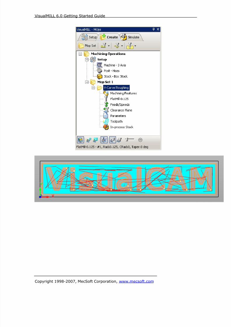
8/16/2019 Visual Mill Getting Started Guide
http://slidepdf.com/reader/full/visual-mill-getting-started-guide 172/411

8/16/2019 Visual Mill Getting Started Guide
http://slidepdf.com/reader/full/visual-mill-getting-started-guide 173/411
VisualMILL 6.0 Getting Started Guide
Copyright 1998-2007, MecSoft Corporation, www.mecsoft.com
Simulate ToolpathThe generated toolpath can now be simulated.
1. Switch to the Simulate tab in the VisualMILL-MOps browser.
2. Select the V-Carving Operation and click to Simulate.
3. The simulated part is as shown below.
Note: You can adjust the simulation speed by selecting Simulation Preferences that islocated to the bottom right corner of the VisualMILL-MOps browser.
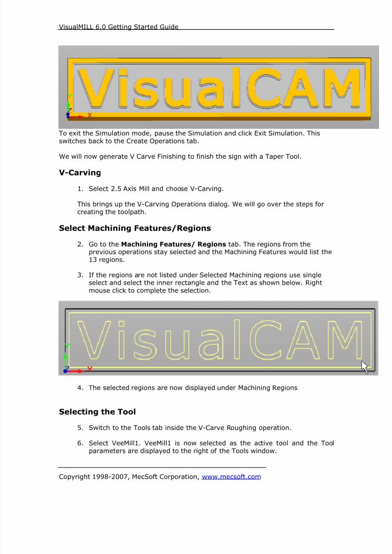
8/16/2019 Visual Mill Getting Started Guide
http://slidepdf.com/reader/full/visual-mill-getting-started-guide 174/411
VisualMILL 6.0 Getting Started Guide
Copyright 1998-2007, MecSoft Corporation, www.mecsoft.com
To exit the Simulation mode, pause the Simulation and click Exit Simulation. This
switches back to the Create Operations tab.
We will now generate V Carve Finishing to finish the sign with a Taper Tool.
V-Carving
1. Select 2.5 Axis Mill and choose V-Carving.
This brings up the V-Carving Operations dialog. We will go over the steps for
creating the toolpath.
Select Machining Features/Regions
2. Go to the Machining Features/ Regions tab. The regions from theprevious operations stay selected and the Machining Features would list the
13 regions.
3. If the regions are not listed under Selected Machining regions use singleselect and select the inner rectangle and the Text as shown below. Right
mouse click to complete the selection.
4. The selected regions are now displayed under Machining Regions
Selecting the Tool
5. Switch to the Tools tab inside the V-Carve Roughing operation.
6. Select VeeMill1. VeeMill1 is now selected as the active tool and the Tool
parameters are displayed to the right of the Tools window.

8/16/2019 Visual Mill Getting Started Guide
http://slidepdf.com/reader/full/visual-mill-getting-started-guide 175/411
VisualMILL 6.0 Getting Started Guide
Copyright 1998-2007, MecSoft Corporation, www.mecsoft.com
Set Feeds and Speeds
7. Click on the Feeds and Speeds tab.
8. Select Load From Tool. VisualMILL will now get the feeds and speedsinformation that was set when the tool was defined.
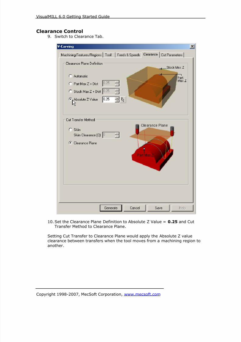
8/16/2019 Visual Mill Getting Started Guide
http://slidepdf.com/reader/full/visual-mill-getting-started-guide 176/411
VisualMILL 6.0 Getting Started Guide
Copyright 1998-2007, MecSoft Corporation, www.mecsoft.com
Clearance Control9. Switch to Clearance Tab.
10. Set the Clearance Plane Definition to Absolute Z Value = 0.25 and CutTransfer Method to Clearance Plane.
Setting Cut Transfer to Clearance Plane would apply the Absolute Z value
clearance between transfers when the tool moves from a machining region toanother.
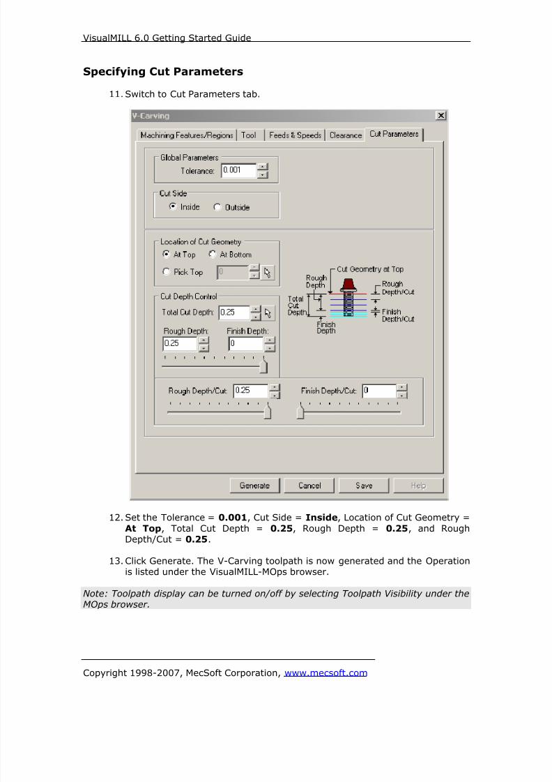
8/16/2019 Visual Mill Getting Started Guide
http://slidepdf.com/reader/full/visual-mill-getting-started-guide 177/411
VisualMILL 6.0 Getting Started Guide
Copyright 1998-2007, MecSoft Corporation, www.mecsoft.com
Specifying Cut Parameters
11. Switch to Cut Parameters tab.
12. Set the Tolerance = 0.001, Cut Side = Inside, Location of Cut Geometry =
At Top, Total Cut Depth = 0.25, Rough Depth = 0.25, and RoughDepth/Cut = 0.25.
13. Click Generate. The V-Carving toolpath is now generated and the Operationis listed under the VisualMILL-MOps browser.
Note: Toolpath display can be turned on/off by selecting Toolpath Visibility under theMOps browser.

8/16/2019 Visual Mill Getting Started Guide
http://slidepdf.com/reader/full/visual-mill-getting-started-guide 178/411
VisualMILL 6.0 Getting Started Guide
Copyright 1998-2007, MecSoft Corporation, www.mecsoft.com

8/16/2019 Visual Mill Getting Started Guide
http://slidepdf.com/reader/full/visual-mill-getting-started-guide 179/411
VisualMILL 6.0 Getting Started Guide
Copyright 1998-2007, MecSoft Corporation, www.mecsoft.com
Simulate ToolpathThe generated toolpath can now be simulated.
1. Switch to the Simulate tab in the VisualMILL-MOps browser and Select theV-Carving Operation and click to Simulate.
2. The Simulated part is as shown below.
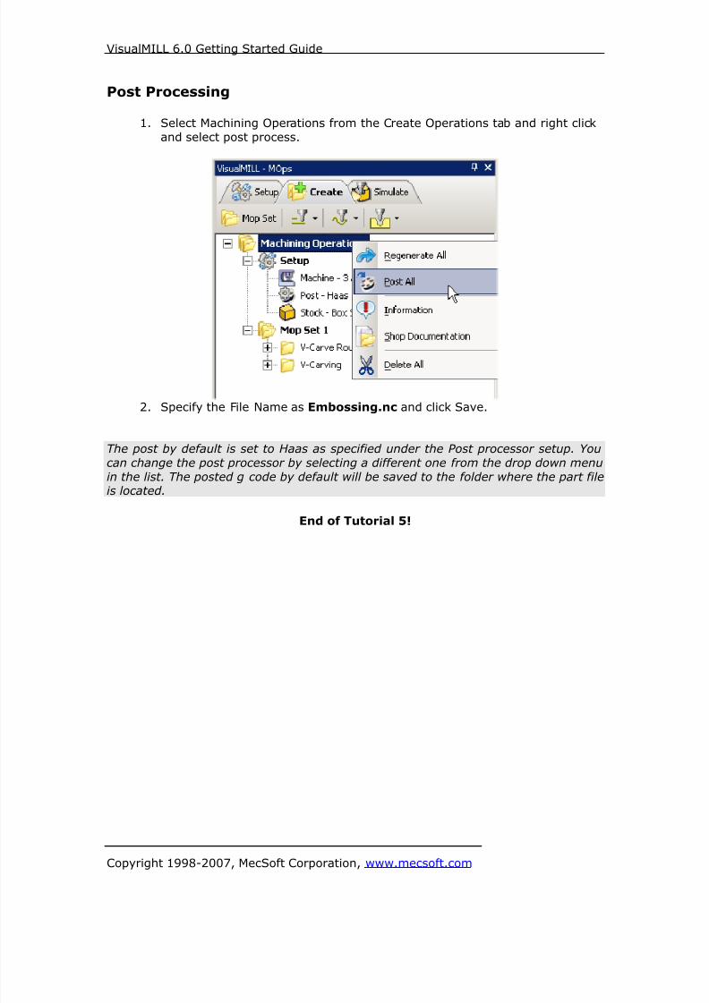
8/16/2019 Visual Mill Getting Started Guide
http://slidepdf.com/reader/full/visual-mill-getting-started-guide 180/411
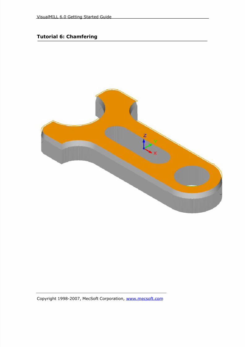
8/16/2019 Visual Mill Getting Started Guide
http://slidepdf.com/reader/full/visual-mill-getting-started-guide 181/411
VisualMILL 6.0 Getting Started Guide
Copyright 1998-2007, MecSoft Corporation, www.mecsoft.com
Tutorial 6: Chamfering
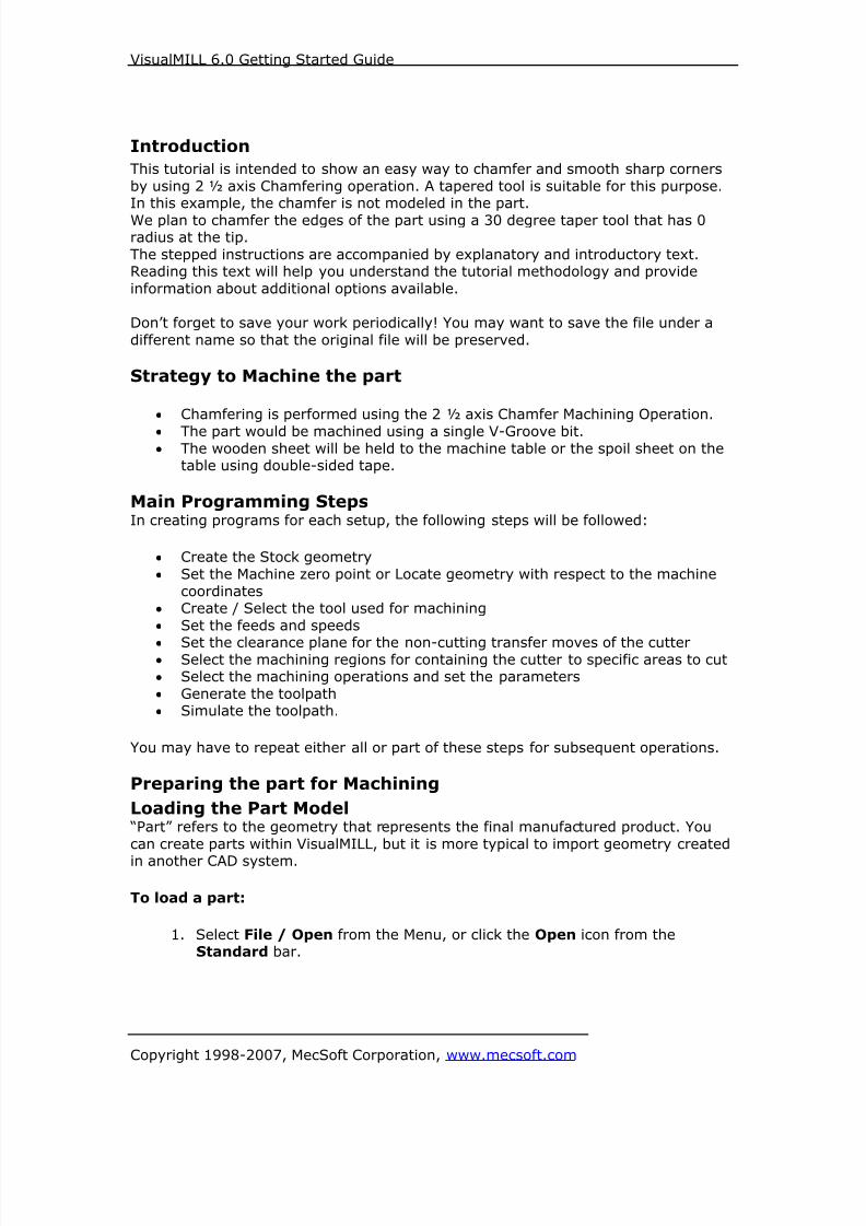
8/16/2019 Visual Mill Getting Started Guide
http://slidepdf.com/reader/full/visual-mill-getting-started-guide 182/411
VisualMILL 6.0 Getting Started Guide
Copyright 1998-2007, MecSoft Corporation, www.mecsoft.com
Introduction
This tutorial is intended to show an easy way to chamfer and smooth sharp corners
by using 2 ½ axis Chamfering operation. A tapered tool is suitable for this purpose.In this example, the chamfer is not modeled in the part.
We plan to chamfer the edges of the part using a 30 degree taper tool that has 0radius at the tip.
The stepped instructions are accompanied by explanatory and introductory text.Reading this text will help you understand the tutorial methodology and provide
information about additional options available.
Don’t forget to save your work periodically! You may want to save the file under a
different name so that the original file will be preserved.
Strategy to Machine the part
• Chamfering is performed using the 2 ½ axis Chamfer Machining Operation.
• The part would be machined using a single V-Groove bit.• The wooden sheet will be held to the machine table or the spoil sheet on the
table using double-sided tape.
Main Programming StepsIn creating programs for each setup, the following steps will be followed:
• Create the Stock geometry
• Set the Machine zero point or Locate geometry with respect to the machine
coordinates
• Create / Select the tool used for machining
• Set the feeds and speeds
• Set the clearance plane for the non-cutting transfer moves of the cutter• Select the machining regions for containing the cutter to specific areas to cut
• Select the machining operations and set the parameters
• Generate the toolpath
• Simulate the toolpath.
You may have to repeat either all or part of these steps for subsequent operations.
Preparing the part for Machining
Loading the Part Model “Part” refers to the geometry that represents the final manufactured product. You
can create parts within VisualMILL, but it is more typical to import geometry created
in another CAD system.
To load a part:
1. Select File / Open from the Menu, or click the Open icon from theStandard bar.

8/16/2019 Visual Mill Getting Started Guide
http://slidepdf.com/reader/full/visual-mill-getting-started-guide 183/411
VisualMILL 6.0 Getting Started Guide
Copyright 1998-2007, MecSoft Corporation, www.mecsoft.com
2. From the Open dialog box, select the Chamfer.vcp file from the Tutorials folder in the VisualMILL 6.0 installation folder. (C:\Program Files\MecSoft
Corporation\VisualCAM 1.0\Plug-ins\VisualMILL 6.0\Tutorials)
The imported part appears as shown below

8/16/2019 Visual Mill Getting Started Guide
http://slidepdf.com/reader/full/visual-mill-getting-started-guide 184/411
VisualMILL 6.0 Getting Started Guide
Copyright 1998-2007, MecSoft Corporation, www.mecsoft.com
Setup Tab
1. Go to the VisualMILL- MOps browser and click on the Setup tab. The loaded
part has the stock model defined and includes a 2 ½ axis Facing Operationwith a 0.5” Flat End Mill. The Machining Operation information is listed in
the MOps browser as shown below.

8/16/2019 Visual Mill Getting Started Guide
http://slidepdf.com/reader/full/visual-mill-getting-started-guide 185/411
VisualMILL 6.0 Getting Started Guide
Copyright 1998-2007, MecSoft Corporation, www.mecsoft.com
Create Tools
To machine the chamfer, we will now create a 60-degree Taper Tool.
1. Go to the VisualMILL-Tools browser that is located below the VisualMILL-
MOps browser and select Create/Edit Tools. Select the Tool Type toChamfer.
2. Set the tool name as ChamferMill1, Taper Angle = 30, Flute Length = 1,and Tool Length = 2. Under the Properties tab, set Tool Number = 2.
Note: Taper Angle represents the included angle for a taper tool. For example a 60-degree taper tool would have a included angle of 30 degrees. If you have a taper
tool with a diameter select Chamfer Mill or Taper Mill under Create/Select Tool.
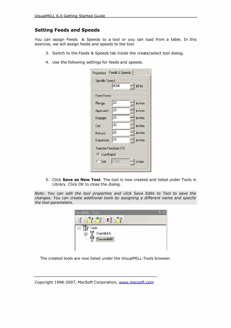
8/16/2019 Visual Mill Getting Started Guide
http://slidepdf.com/reader/full/visual-mill-getting-started-guide 186/411
VisualMILL 6.0 Getting Started Guide
Copyright 1998-2007, MecSoft Corporation, www.mecsoft.com
Setting Feeds and Speeds
You can assign Feeds & Speeds to a tool or you can load from a table. In this
exercise, we will assign feeds and speeds to the tool.
3. Switch to the Feeds & Speeds tab inside the create/select tool dialog.
4. Use the following settings for feeds and speeds.
5. Click Save as New Tool. The tool is now created and listed under Tools in
Library. Click OK to close the dialog.
Note: You can edit the tool properties and click Save Edits to Tool to save thechanges. You can create additional tools by assigning a different name and specify
the tool parameters.
The created tools are now listed under the VisualMILL-Tools browser.
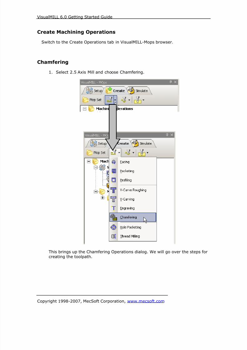
8/16/2019 Visual Mill Getting Started Guide
http://slidepdf.com/reader/full/visual-mill-getting-started-guide 187/411
VisualMILL 6.0 Getting Started Guide
Copyright 1998-2007, MecSoft Corporation, www.mecsoft.com
Create Machining Operations
Switch to the Create Operations tab in VisualMILL-Mops browser.
Chamfering
1. Select 2.5 Axis Mill and choose Chamfering.
This brings up the Chamfering Operations dialog. We will go over the steps forcreating the toolpath.

8/16/2019 Visual Mill Getting Started Guide
http://slidepdf.com/reader/full/visual-mill-getting-started-guide 188/411
VisualMILL 6.0 Getting Started Guide
Copyright 1998-2007, MecSoft Corporation, www.mecsoft.com
Select Machining Features/Regions2. Go to the Machining Features/ Regions tab and click remove all if any
Machining regions are listed.3. Click Select Curves as Regions.
4. Now, select the curve that follows the profile of the spanner as shown
below.
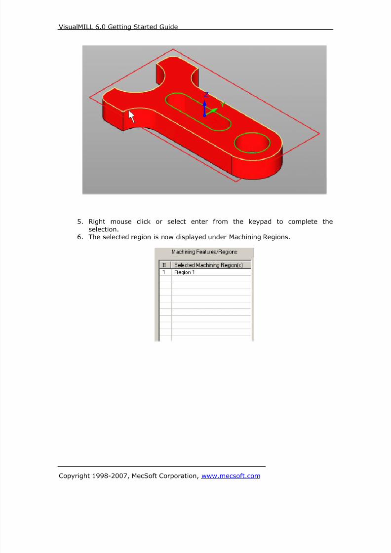
8/16/2019 Visual Mill Getting Started Guide
http://slidepdf.com/reader/full/visual-mill-getting-started-guide 189/411
VisualMILL 6.0 Getting Started Guide
Copyright 1998-2007, MecSoft Corporation, www.mecsoft.com
5. Right mouse click or select enter from the keypad to complete the
selection.6. The selected region is now displayed under Machining Regions.

8/16/2019 Visual Mill Getting Started Guide
http://slidepdf.com/reader/full/visual-mill-getting-started-guide 190/411
VisualMILL 6.0 Getting Started Guide
Copyright 1998-2007, MecSoft Corporation, www.mecsoft.com
Selecting the Tool
7. Switch to the Tools tab inside the Chamfering operation.
8. Select ChamferMill1. ChamferMill1 is now selected as the active tool, and
the Tool parameters are displayed to the right of the Tools window.

8/16/2019 Visual Mill Getting Started Guide
http://slidepdf.com/reader/full/visual-mill-getting-started-guide 191/411
VisualMILL 6.0 Getting Started Guide
Copyright 1998-2007, MecSoft Corporation, www.mecsoft.com
Set Feeds and Speeds9. Click on the Feeds and Speeds tab.
10. Select Load From Tool. VisualMILL will now get the feeds and speeds
information that was set when the tool was defined.
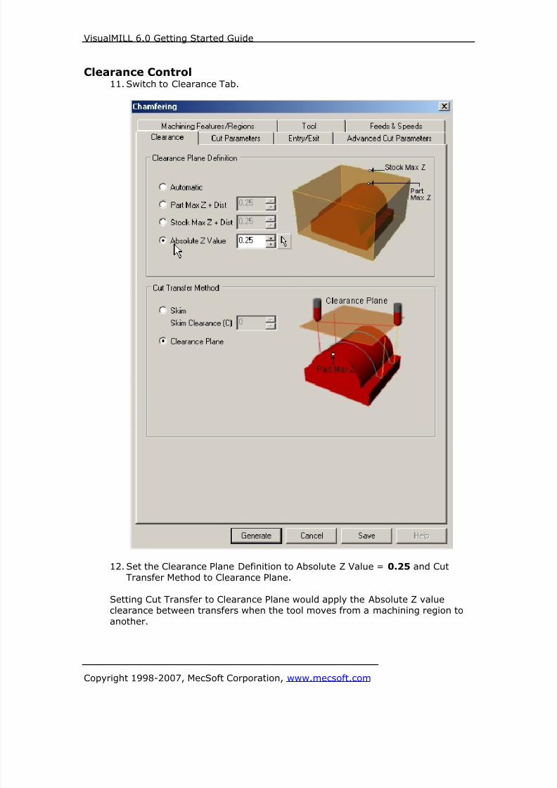
8/16/2019 Visual Mill Getting Started Guide
http://slidepdf.com/reader/full/visual-mill-getting-started-guide 192/411
VisualMILL 6.0 Getting Started Guide
Copyright 1998-2007, MecSoft Corporation, www.mecsoft.com
Clearance Control11. Switch to Clearance Tab.
12. Set the Clearance Plane Definition to Absolute Z Value = 0.25 and Cut
Transfer Method to Clearance Plane.
Setting Cut Transfer to Clearance Plane would apply the Absolute Z valueclearance between transfers when the tool moves from a machining region to
another.

8/16/2019 Visual Mill Getting Started Guide
http://slidepdf.com/reader/full/visual-mill-getting-started-guide 193/411
VisualMILL 6.0 Getting Started Guide
Copyright 1998-2007, MecSoft Corporation, www.mecsoft.com
Specifying Cut Parameters
13. Switch to Cut Parameters tab.
14. Set the Tolerance = 0.001, Stock = 0, Chamfer Parameters use Chamfer
Width = 0.05, Cut Side = Outside. Click Generate. The Chamferingtoolpath is now generated and the Operation is listed under the VisualMILL-
MOps browser.
Note: Toolpath display can be turned on/off by selecting Toolpath Visibility under the
MOps browser.
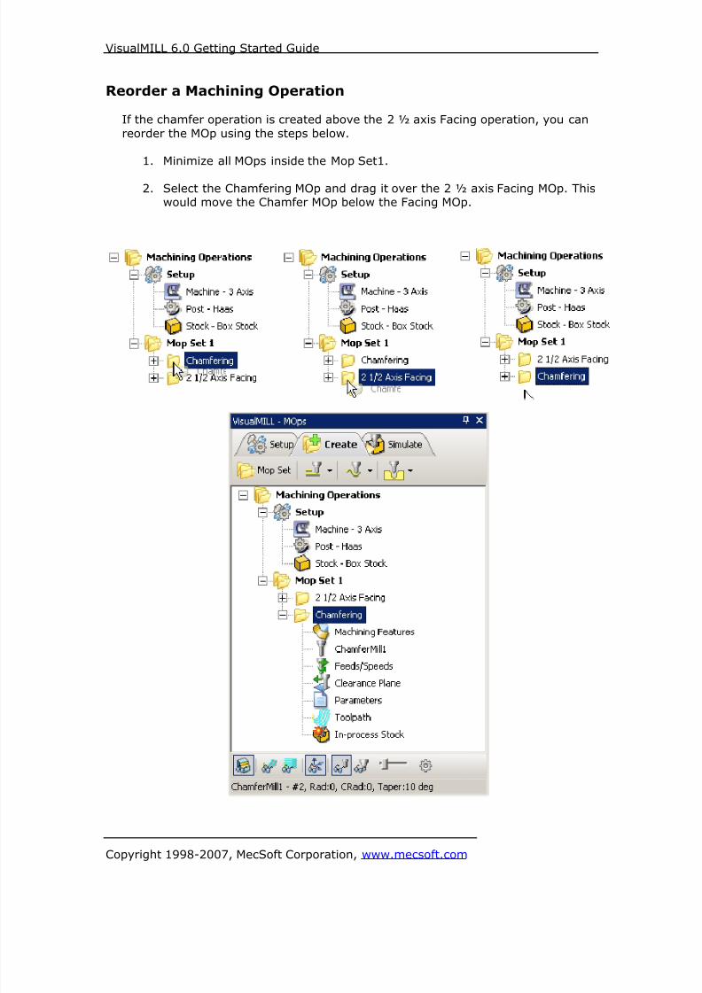
8/16/2019 Visual Mill Getting Started Guide
http://slidepdf.com/reader/full/visual-mill-getting-started-guide 194/411
VisualMILL 6.0 Getting Started Guide
Copyright 1998-2007, MecSoft Corporation, www.mecsoft.com
Reorder a Machining Operation
If the chamfer operation is created above the 2 ½ axis Facing operation, you can
reorder the MOp using the steps below.
1. Minimize all MOps inside the Mop Set1.
2. Select the Chamfering MOp and drag it over the 2 ½ axis Facing MOp. Thiswould move the Chamfer MOp below the Facing MOp.

8/16/2019 Visual Mill Getting Started Guide
http://slidepdf.com/reader/full/visual-mill-getting-started-guide 195/411
VisualMILL 6.0 Getting Started Guide
Copyright 1998-2007, MecSoft Corporation, www.mecsoft.com
Simulate ToolpathThe generated toolpath can now be simulated.
1. Switch to the Simulate tab in the VisualMILL-MOps browser.
2. Select the 2 ½ Axis Facing Operation and click to Simulate.
3. Once the Facing operation is simulated, select the Chamfering Operationand click Simulate to run the simulation.
4. The simulated part is as shown below.
Note: You can adjust the simulation speed by selecting Simulation Preferences that is
located to the bottom right corner of the VisualMILL-MOps browser.
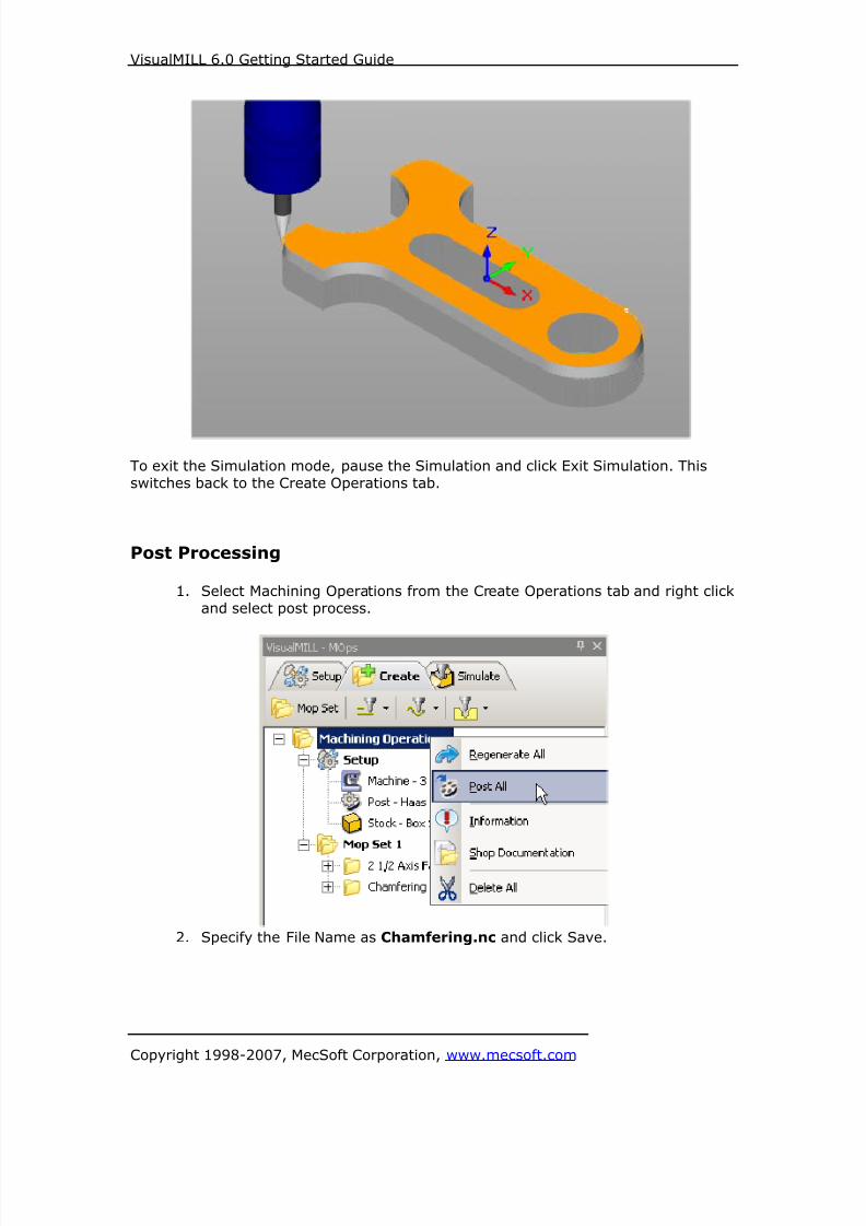
8/16/2019 Visual Mill Getting Started Guide
http://slidepdf.com/reader/full/visual-mill-getting-started-guide 196/411
VisualMILL 6.0 Getting Started Guide
Copyright 1998-2007, MecSoft Corporation, www.mecsoft.com
To exit the Simulation mode, pause the Simulation and click Exit Simulation. This
switches back to the Create Operations tab.
Post Processing
1. Select Machining Operations from the Create Operations tab and right click
and select post process.
2. Specify the File Name as Chamfering.nc and click Save.

8/16/2019 Visual Mill Getting Started Guide
http://slidepdf.com/reader/full/visual-mill-getting-started-guide 197/411
VisualMILL 6.0 Getting Started Guide
Copyright 1998-2007, MecSoft Corporation, www.mecsoft.com
The post by default is set to Haas as specified under the Post processor setup. You
can change the post processor by selecting a different one from the drop down menu
in the list. The posted g code by default will be saved to the folder where the part fileis located.
End of Tutorial 6!

8/16/2019 Visual Mill Getting Started Guide
http://slidepdf.com/reader/full/visual-mill-getting-started-guide 198/411
VisualMILL 6.0 Getting Started Guide
Copyright 1998-2007, MecSoft Corporation, www.mecsoft.com
Tutorial 7: 3 Axis Milling

8/16/2019 Visual Mill Getting Started Guide
http://slidepdf.com/reader/full/visual-mill-getting-started-guide 199/411
VisualMILL 6.0 Getting Started Guide
Copyright 1998-2007, MecSoft Corporation, www.mecsoft.com
Introduction
This tutorial will illustrate machining this Mold using 3 axis-milling operations.
This tutorial will introduce the usage of several 3-axis operations such as horizontalroughing, parallel finishing, and horizontal finishing.
The stepped instructions are accompanied by explanatory and introductory text.Reading this text will help you understand the tutorial methodology and provide
information about additional options available.
Don’t forget to save your work periodically! You may want to save the file under a
different name so that the original file will be preserved.
Strategy to Machine the mold
• We will machine the mold completely using 3 axis-machining operations.
• The part itself will be machined out of a 5.5 x 6.5 inch x 1.25-inch wood
block.• The stock may be held to the machine table or the spoil sheet on the table
using double-sided tape or by clamps.• The part will be machined using 0.5” flat end mill, 0.25” & 0.125” ball end
mills.
Main Programming StepsIn creating programs for each setup, the following steps will be followed:
• Create the Stock geometry
• Set the Machine zero point or Locate geometry with respect to the machine
coordinates
• Create / Select the tool used for machining
• Set the feeds and speeds• Set the clearance plane for the non-cutting transfer moves of the cutter
• Select the machining regions for containing the cutter to specific areas to cut
• Select the machining operations and set the parameters
• Generate the toolpath
• Simulate the toolpath.
You may have to repeat either all or part of these steps for subsequent operations.
Preparing the part for Machining
Loading the Part Model
“Part” refers to the geometry that represents the final manufactured product. Youcan create parts within VisualMILL, but it is more typical to import geometry created
in another CAD system.
To load a part:
1. Select File / Open from the Menu, or click the Open icon from theStandard bar.

8/16/2019 Visual Mill Getting Started Guide
http://slidepdf.com/reader/full/visual-mill-getting-started-guide 200/411
VisualMILL 6.0 Getting Started Guide
Copyright 1998-2007, MecSoft Corporation, www.mecsoft.com
2. From the Open dialog box, select the 3Axis_Example1.vcp file from the
Tutorials folder in the VisualMILL 6.0 installation folder. (C:\Program
Files\MecSoft Corporation\VisualCAM 1.0\Plug-ins\VisualMILL 6.0\Tutorials)
The imported part appears as shown below

8/16/2019 Visual Mill Getting Started Guide
http://slidepdf.com/reader/full/visual-mill-getting-started-guide 201/411
VisualMILL 6.0 Getting Started Guide
Copyright 1998-2007, MecSoft Corporation, www.mecsoft.com
Setup Tab
1. Go to the VisualMILL- MOps browser and click on the Setup tab.
2. Select Machine Setup from the setup tab.
3. Set the Machine type to 3 axis.
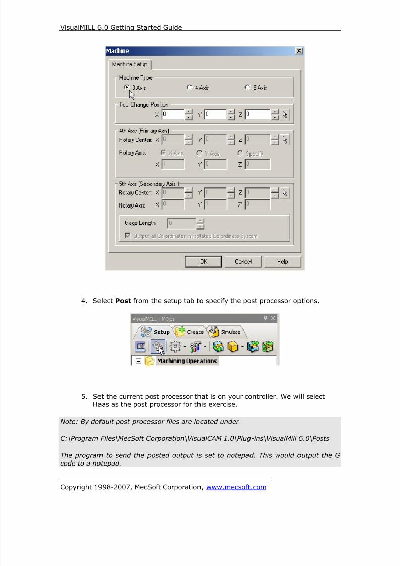
8/16/2019 Visual Mill Getting Started Guide
http://slidepdf.com/reader/full/visual-mill-getting-started-guide 202/411
VisualMILL 6.0 Getting Started Guide
Copyright 1998-2007, MecSoft Corporation, www.mecsoft.com
4. Select Post from the setup tab to specify the post processor options.
5. Set the current post processor that is on your controller. We will selectHaas as the post processor for this exercise.
Note: By default post processor files are located under
C:\Program Files\MecSoft Corporation\VisualCAM 1.0\Plug-ins\VisualMill 6.0\Posts
The program to send the posted output is set to notepad. This would output the G
code to a notepad.

8/16/2019 Visual Mill Getting Started Guide
http://slidepdf.com/reader/full/visual-mill-getting-started-guide 203/411
VisualMILL 6.0 Getting Started Guide
Copyright 1998-2007, MecSoft Corporation, www.mecsoft.com
Create Stock Geometry
1. Select Create/Load stock from the setup tab and create a Box Stock.
2. This brings up the Box Stock parameters. Set the Length (L) = 5.50,Width W = 6.50, and Height (H) = 1.25. Leave the other parameters as
default and click OK.

8/16/2019 Visual Mill Getting Started Guide
http://slidepdf.com/reader/full/visual-mill-getting-started-guide 204/411
VisualMILL 6.0 Getting Started Guide
Copyright 1998-2007, MecSoft Corporation, www.mecsoft.com
3. The stock geometry is now created, and a semi-transparent stock box isdisplayed on top of the part geometry.
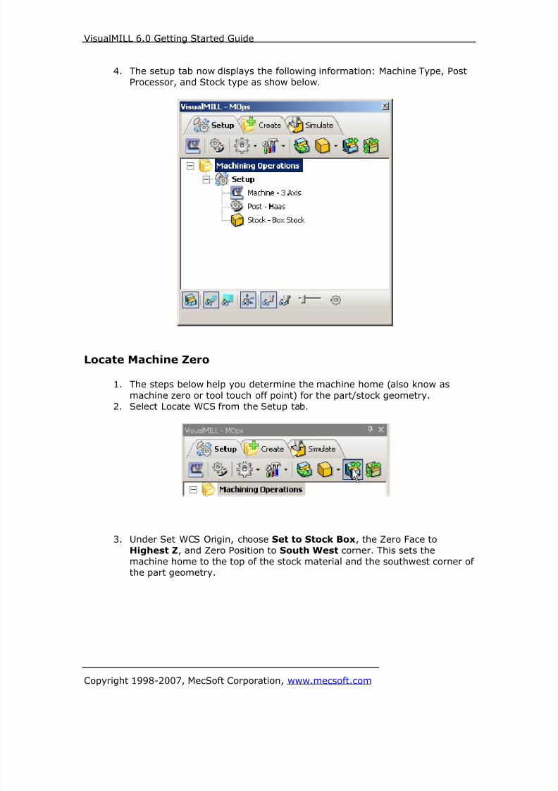
8/16/2019 Visual Mill Getting Started Guide
http://slidepdf.com/reader/full/visual-mill-getting-started-guide 205/411

8/16/2019 Visual Mill Getting Started Guide
http://slidepdf.com/reader/full/visual-mill-getting-started-guide 206/411
VisualMILL 6.0 Getting Started Guide
Copyright 1998-2007, MecSoft Corporation, www.mecsoft.com
Note: You can change the stock model transparency under standard mode by
selecting Simulation Preferences that is located at the bottom of the MOps browser.
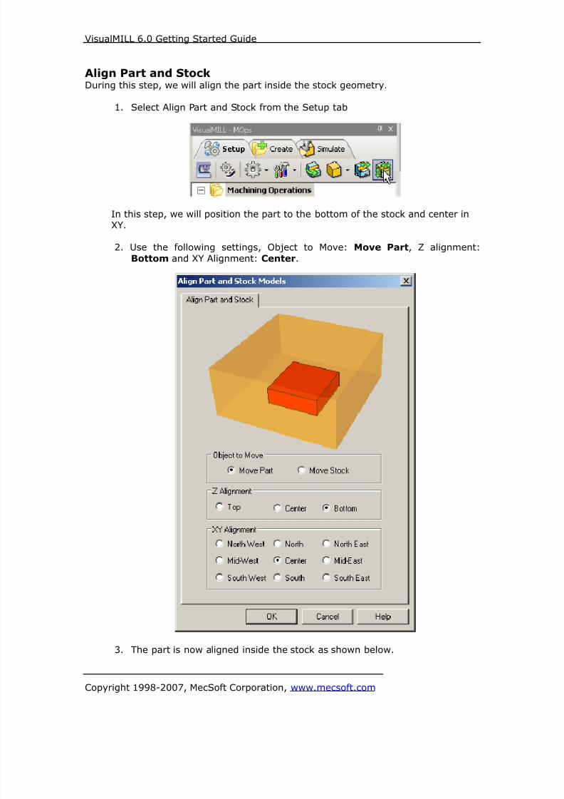
8/16/2019 Visual Mill Getting Started Guide
http://slidepdf.com/reader/full/visual-mill-getting-started-guide 207/411
VisualMILL 6.0 Getting Started Guide
Copyright 1998-2007, MecSoft Corporation, www.mecsoft.com
Align Part and StockDuring this step, we will align the part inside the stock geometry.
1. Select Align Part and Stock from the Setup tab
In this step, we will position the part to the bottom of the stock and center inXY.
2. Use the following settings, Object to Move: Move Part, Z alignment:
Bottom and XY Alignment: Center.
3. The part is now aligned inside the stock as shown below.
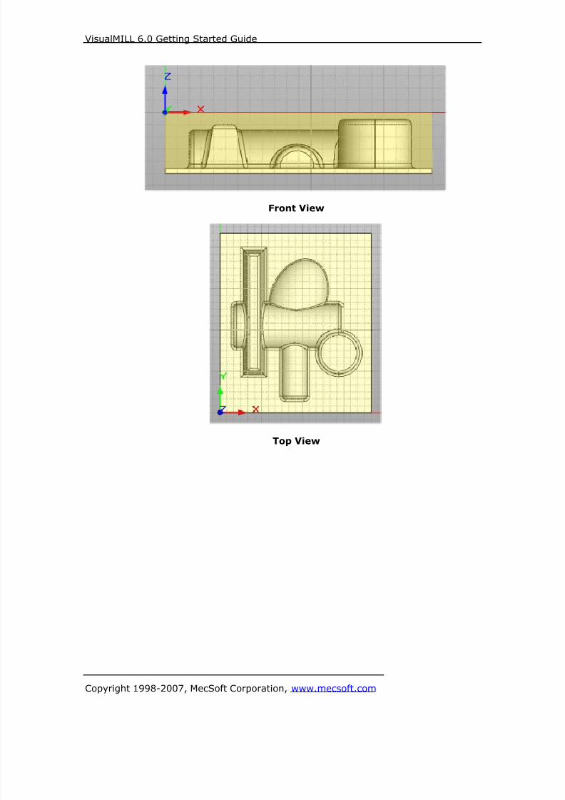
8/16/2019 Visual Mill Getting Started Guide
http://slidepdf.com/reader/full/visual-mill-getting-started-guide 208/411
VisualMILL 6.0 Getting Started Guide
Copyright 1998-2007, MecSoft Corporation, www.mecsoft.com
Front View
Top View
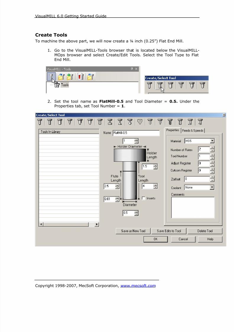
8/16/2019 Visual Mill Getting Started Guide
http://slidepdf.com/reader/full/visual-mill-getting-started-guide 209/411
VisualMILL 6.0 Getting Started Guide
Copyright 1998-2007, MecSoft Corporation, www.mecsoft.com
Create Tools
To machine the above part, we will now create a ¼ inch (0.25”) Flat End Mill.
1. Go to the VisualMILL-Tools browser that is located below the VisualMILL-MOps browser and select Create/Edit Tools. Select the Tool Type to Flat
End Mill.
2. Set the tool name as FlatMill-0.5 and Tool Diameter = 0.5. Under theProperties tab, set Tool Number = 1.
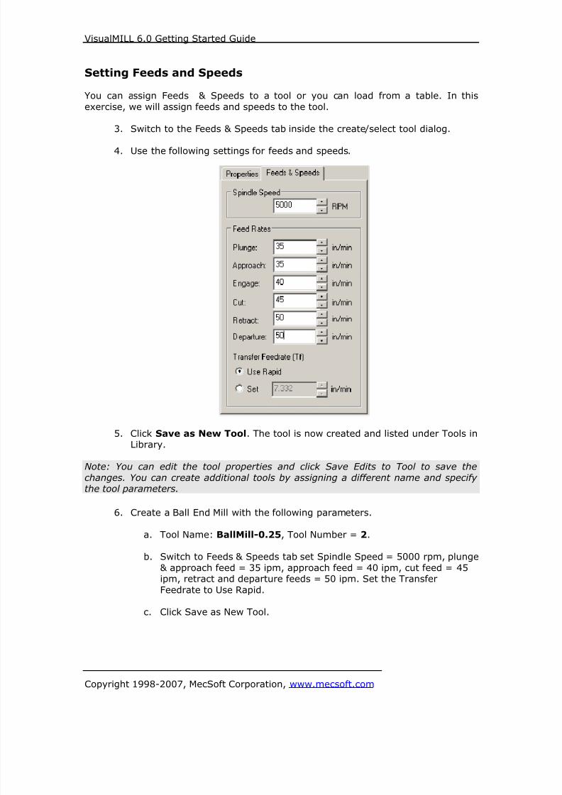
8/16/2019 Visual Mill Getting Started Guide
http://slidepdf.com/reader/full/visual-mill-getting-started-guide 210/411
VisualMILL 6.0 Getting Started Guide
Copyright 1998-2007, MecSoft Corporation, www.mecsoft.com
Setting Feeds and Speeds
You can assign Feeds & Speeds to a tool or you can load from a table. In this
exercise, we will assign feeds and speeds to the tool.
3. Switch to the Feeds & Speeds tab inside the create/select tool dialog.
4. Use the following settings for feeds and speeds.
5. Click Save as New Tool. The tool is now created and listed under Tools inLibrary.
Note: You can edit the tool properties and click Save Edits to Tool to save the
changes. You can create additional tools by assigning a different name and specifythe tool parameters.
6. Create a Ball End Mill with the following parameters.
a. Tool Name: BallMill-0.25, Tool Number = 2.
b. Switch to Feeds & Speeds tab set Spindle Speed = 5000 rpm, plunge& approach feed = 35 ipm, approach feed = 40 ipm, cut feed = 45ipm, retract and departure feeds = 50 ipm. Set the Transfer
Feedrate to Use Rapid.
c. Click Save as New Tool.

8/16/2019 Visual Mill Getting Started Guide
http://slidepdf.com/reader/full/visual-mill-getting-started-guide 211/411
VisualMILL 6.0 Getting Started Guide
Copyright 1998-2007, MecSoft Corporation, www.mecsoft.com
7. Create another Ball End Mill with the following parameters.
d. Tool Name: BallMill-0.125, Tool Number = 3.
e. Switch to Feeds & Speeds tab set Spindle Speed = 5000 rpm, plunge
& approach feed = 35 ipm, approach feed = 40 ipm, cut feed = 45
ipm, retract and departure feeds = 50 ipm. Set the TransferFeedrate to Use Rapid.
f. Click Save as New Tool.
The created tools are now listed under the VisualMILL-Tools browser.
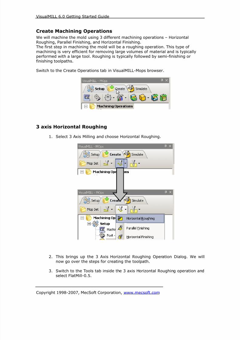
8/16/2019 Visual Mill Getting Started Guide
http://slidepdf.com/reader/full/visual-mill-getting-started-guide 212/411
VisualMILL 6.0 Getting Started Guide
Copyright 1998-2007, MecSoft Corporation, www.mecsoft.com
Create Machining Operations
We will machine the mold using 3 different machining operations – Horizontal
Roughing, Parallel Finishing, and Horizontal Finishing.The first step in machining the mold will be a roughing operation. This type of
machining is very efficient for removing large volumes of material and is typicallyperformed with a large tool. Roughing is typically followed by semi-finishing or
finishing toolpaths.
Switch to the Create Operations tab in VisualMILL-Mops browser.
3 axis Horizontal Roughing
1. Select 3 Axis Milling and choose Horizontal Roughing.
2. This brings up the 3 Axis Horizontal Roughing Operation Dialog. We will
now go over the steps for creating the toolpath.
3. Switch to the Tools tab inside the 3 axis Horizontal Roughing operation and
select FlatMill-0.5.
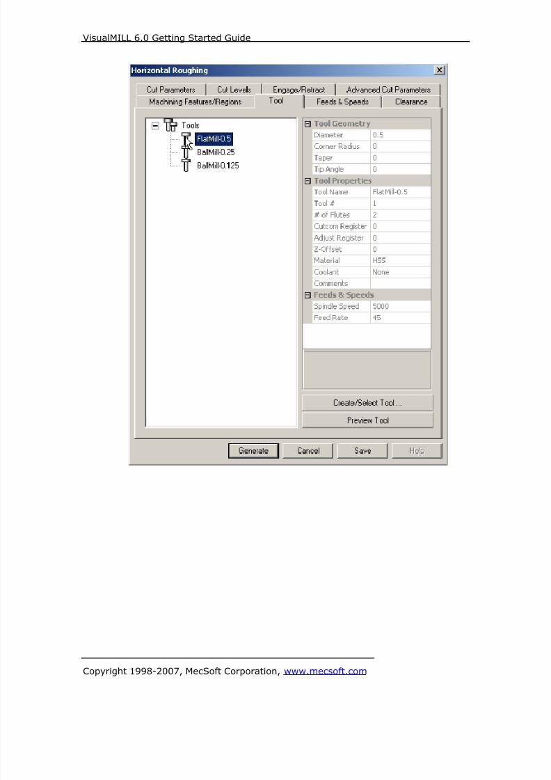
8/16/2019 Visual Mill Getting Started Guide
http://slidepdf.com/reader/full/visual-mill-getting-started-guide 213/411
VisualMILL 6.0 Getting Started Guide
Copyright 1998-2007, MecSoft Corporation, www.mecsoft.com

8/16/2019 Visual Mill Getting Started Guide
http://slidepdf.com/reader/full/visual-mill-getting-started-guide 214/411
VisualMILL 6.0 Getting Started Guide
Copyright 1998-2007, MecSoft Corporation, www.mecsoft.com
4. Click on the Feeds and Speeds tab and select Load From Tool. VisualMILL
will now get the feeds and speeds information that was set when the toolwas defined.

8/16/2019 Visual Mill Getting Started Guide
http://slidepdf.com/reader/full/visual-mill-getting-started-guide 215/411
VisualMILL 6.0 Getting Started Guide
Copyright 1998-2007, MecSoft Corporation, www.mecsoft.com
5. Switch to the Clearance Tab and set the Clearance Plane Definition to
Automatic and Cut Transfer Method to Clearance Plane.
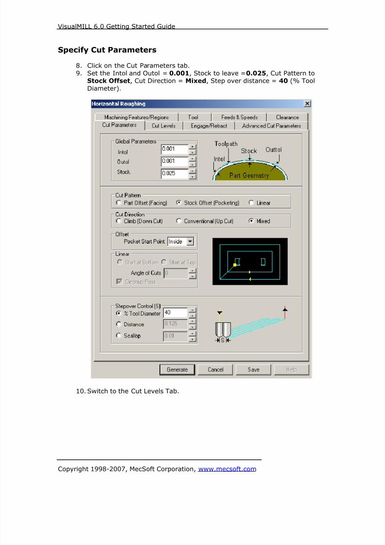
8/16/2019 Visual Mill Getting Started Guide
http://slidepdf.com/reader/full/visual-mill-getting-started-guide 216/411
VisualMILL 6.0 Getting Started Guide
Copyright 1998-2007, MecSoft Corporation, www.mecsoft.com
Specify Cut Parameters
8. Click on the Cut Parameters tab.
9. Set the Intol and Outol = 0.001, Stock to leave =0.025, Cut Pattern toStock Offset, Cut Direction = Mixed, Step over distance = 40 (% Tool
Diameter).
10. Switch to the Cut Levels Tab.

8/16/2019 Visual Mill Getting Started Guide
http://slidepdf.com/reader/full/visual-mill-getting-started-guide 217/411
VisualMILL 6.0 Getting Started Guide
Copyright 1998-2007, MecSoft Corporation, www.mecsoft.com
11. Use the Following Settings.
a. Step Down Control (dZ) = 25 (% Tool Diameter).
b. Check Clear Flats under Cut Levels.
12. Switch to the Engage/Retract tab and leave the entry/exit parameters as
default.
13. Click Generate. The 3 axis Roughing toolpath is now generated, and theOperation is listed under the VisualMILL-MOps browser.
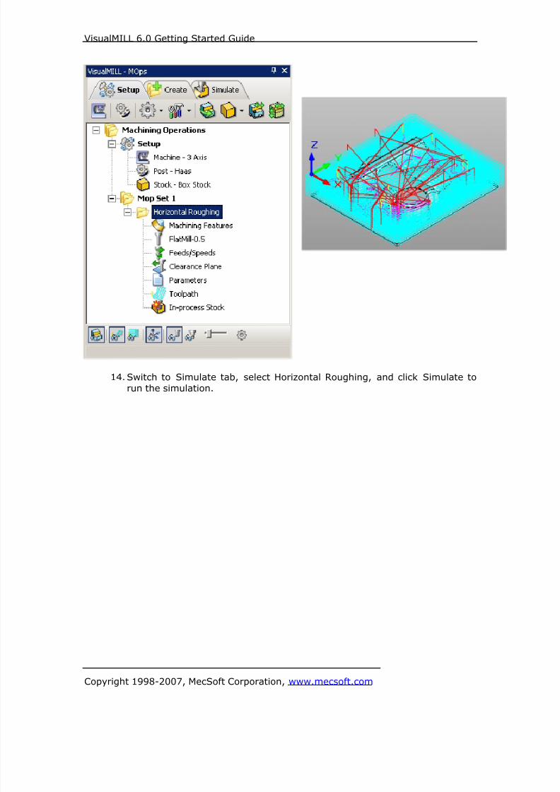
8/16/2019 Visual Mill Getting Started Guide
http://slidepdf.com/reader/full/visual-mill-getting-started-guide 218/411
VisualMILL 6.0 Getting Started Guide
Copyright 1998-2007, MecSoft Corporation, www.mecsoft.com
14. Switch to Simulate tab, select Horizontal Roughing, and click Simulate to
run the simulation.

8/16/2019 Visual Mill Getting Started Guide
http://slidepdf.com/reader/full/visual-mill-getting-started-guide 219/411
VisualMILL 6.0 Getting Started Guide
Copyright 1998-2007, MecSoft Corporation, www.mecsoft.com
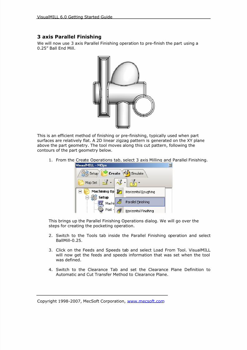
8/16/2019 Visual Mill Getting Started Guide
http://slidepdf.com/reader/full/visual-mill-getting-started-guide 220/411
VisualMILL 6.0 Getting Started Guide
Copyright 1998-2007, MecSoft Corporation, www.mecsoft.com
3 axis Parallel Finishing
We will now use 3 axis Parallel Finishing operation to pre-finish the part using a
0.25” Ball End Mill.
This is an efficient method of finishing or pre-finishing, typically used when part
surfaces are relatively flat. A 2D linear zigzag pattern is generated on the XY planeabove the part geometry. The tool moves along this cut pattern, following the
contours of the part geometry below.
1. From the Create Operations tab, select 3 axis Milling and Parallel Finishing.
This brings up the Parallel Finishing Operations dialog. We will go over the
steps for creating the pocketing operation.
2. Switch to the Tools tab inside the Parallel Finishing operation and select
BallMill-0.25.
3. Click on the Feeds and Speeds tab and select Load From Tool. VisualMILL
will now get the feeds and speeds information that was set when the tool
was defined.
4. Switch to the Clearance Tab and set the Clearance Plane Definition to
Automatic and Cut Transfer Method to Clearance Plane.

8/16/2019 Visual Mill Getting Started Guide
http://slidepdf.com/reader/full/visual-mill-getting-started-guide 221/411
VisualMILL 6.0 Getting Started Guide
Copyright 1998-2007, MecSoft Corporation, www.mecsoft.com
Specify Cut Parameters
5. Click on the Cut Parameters tab.
6. Set the Tolerance to 0.001, Stock to leave =0, Cut Direction = Mixed, Stepover distance = 15 (% Tool Diameter).
7. Click Generate. The Parallel Finishing toolpath is now generated, and the
Operation is listed under the 3 Axis Horizontal Roughing Operation in theVisualMILL-MOps browser.

8/16/2019 Visual Mill Getting Started Guide
http://slidepdf.com/reader/full/visual-mill-getting-started-guide 222/411
VisualMILL 6.0 Getting Started Guide
Copyright 1998-2007, MecSoft Corporation, www.mecsoft.com
8. Switch to Simulate tab, select Parallel Finishing, and click Simulate to runthe simulation.

8/16/2019 Visual Mill Getting Started Guide
http://slidepdf.com/reader/full/visual-mill-getting-started-guide 223/411
VisualMILL 6.0 Getting Started Guide
Copyright 1998-2007, MecSoft Corporation, www.mecsoft.com
3 axis Horizontal Finishing
We will now create a Horizontal Finishing operation for machining steep area regions.
This method is used for pre-finishing or finishing in constant Z levels, typically used
when the part has large vertical surfaces and when Parallel Finishing will not yieldsatisfactory results.
Preparing the part for Horizontal Finishing
In preparation for the Horizontal Finishing operation, we will now create regions by
extracting curves from the 3D model.
1. Turn off the Stock Model and Toolpath Visibility from the VisualMILL-MOpsbrowser.
2. Open the Layer Manager and select Layer 01 as the Active Layer.
3. Switch to the Top View by double clicking on the Top View under theViewport.
4. Create a rectangle by selecting the Create Rectangle tool that is located on
the Geometry Bar under Lines.
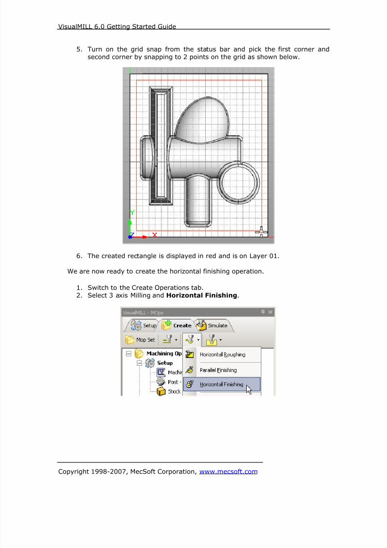
8/16/2019 Visual Mill Getting Started Guide
http://slidepdf.com/reader/full/visual-mill-getting-started-guide 224/411
VisualMILL 6.0 Getting Started Guide
Copyright 1998-2007, MecSoft Corporation, www.mecsoft.com
5. Turn on the grid snap from the status bar and pick the first corner and
second corner by snapping to 2 points on the grid as shown below.
6. The created rectangle is displayed in red and is on Layer 01.
We are now ready to create the horizontal finishing operation.
1. Switch to the Create Operations tab.2. Select 3 axis Milling and Horizontal Finishing.

8/16/2019 Visual Mill Getting Started Guide
http://slidepdf.com/reader/full/visual-mill-getting-started-guide 225/411

8/16/2019 Visual Mill Getting Started Guide
http://slidepdf.com/reader/full/visual-mill-getting-started-guide 226/411
VisualMILL 6.0 Getting Started Guide
Copyright 1998-2007, MecSoft Corporation, www.mecsoft.com
5. Switch to the Tools tab inside Horizontal Finishing operation and selectBallMill-0.125.
6. Click on the Feeds and Speeds tab and select Load From Tool. VisualMILLwill now get the feeds and speeds information that was set when the tool
was defined.
7. Switch to the Clearance Tab and set the Clearance Plane Definition to
Automatic and Cut Transfer Method to Clearance Plane.
Specify Cut Parameters
8. Click on the Cut Parameters tab.
9. Set Intol, Outol = 0.001, Cut Direction = Cilmb/Conventional.
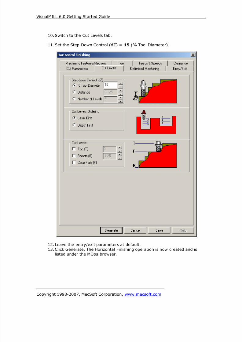
8/16/2019 Visual Mill Getting Started Guide
http://slidepdf.com/reader/full/visual-mill-getting-started-guide 227/411
VisualMILL 6.0 Getting Started Guide
Copyright 1998-2007, MecSoft Corporation, www.mecsoft.com
10. Switch to the Cut Levels tab.
11. Set the Step Down Control (dZ) = 15 (% Tool Diameter).
12. Leave the entry/exit parameters at default.
13. Click Generate. The Horizontal Finishing operation is now created and is
listed under the MOps browser.
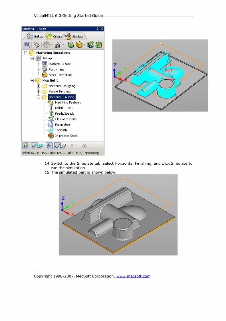
8/16/2019 Visual Mill Getting Started Guide
http://slidepdf.com/reader/full/visual-mill-getting-started-guide 228/411
VisualMILL 6.0 Getting Started Guide
Copyright 1998-2007, MecSoft Corporation, www.mecsoft.com
14. Switch to the Simulate tab, select Horizontal Finishing, and click Simulate to
run the simulation.15. The simulated part is shown below.

8/16/2019 Visual Mill Getting Started Guide
http://slidepdf.com/reader/full/visual-mill-getting-started-guide 229/411
VisualMILL 6.0 Getting Started Guide
Copyright 1998-2007, MecSoft Corporation, www.mecsoft.com
Post Processing
1. Select Machining Operations from the Create Operations tab and right click
and select post process.
2. Specify the File Name as 3axisMold.nc and click save.
The post by default is set to Haas as specified under the Post processor setup. You
can change the post processor by selecting a different one from the drop down menuin the list. The posted g code by default will be saved to the folder where the part file
is located.
End of Tutorial 7!

8/16/2019 Visual Mill Getting Started Guide
http://slidepdf.com/reader/full/visual-mill-getting-started-guide 230/411
VisualMILL 6.0 Getting Started Guide
Copyright 1998-2007, MecSoft Corporation, www.mecsoft.com
Tutorial 8: Profiling with Bridges (Tabs)
8/16/2019 Visual Mill Getting Started Guide
http://slidepdf.com/reader/full/visual-mill-getting-started-guide 231/411
VisualMILL 6.0 Getting Started Guide
Copyright 1998-2007, MecSoft Corporation, www.mecsoft.com
Introduction
This tutorial will illustrate machining of multiple parts on a single sheet of stock using
2-1/2 milling operations.The stepped instructions are accompanied by explanatory and introductory text.
Reading this text will help you understand the tutorial methodology and provideinformation about additional options available.
Don’t forget to save your work periodically! You may want to save the file under a
different name so that the original file will be preserved.
Strategy to Machine the part
• We will machine the part using a 2-½ axis profiling operation.
• We will define bridges so that the parts do not fall off the sheet once its cut to
its full depth.
• The part will be machined out of a 36 x 24 x ½ inch poplar wood sheet using
a 0.25 inch Flat End Mill.• The wooden sheet will be held to the machine table or the spoil sheet on the
table using fixtures/clamps.
Main Programming Steps
In creating programs for each setup, the following steps will be followed:
• Create part geometry
• Create the Stock geometry
• Set the Machine zero point or Locate geometry with respect to the machinecoordinates
• Create / Select the tool used for machining• Set the feeds and speeds• Set the clearance plane for the non-cutting transfer moves of the cutter
• Select the machining regions for containing the cutter to specific areas to cut
• Select the machining operations and set the parameters
• Generate the toolpath
• Simulate the toolpath.
You may have to repeat either all or part of these steps for subsequent operations.
Preparing the part for Machining
Creating the Part Model “Part” refers to the geometry that represents the final manufactured product.
To create a part:
1. Select File / New from the Menu, or click the New icon from the Standard
bar. This creates a new session of VisualCAM.

8/16/2019 Visual Mill Getting Started Guide
http://slidepdf.com/reader/full/visual-mill-getting-started-guide 232/411
VisualMILL 6.0 Getting Started Guide
Copyright 1998-2007, MecSoft Corporation, www.mecsoft.com
2. Switch to the Top View by double-clicking on the Top View under the
Viewport.
3. The part will be modeled in Inches. VisualCAM status bar displays the modelunits. To switch units select Preferences->Part Units
4. Select Preferences from VisualCAM menu and Grid Preferences. Use thefollowing grid settings.
5. Create a rectangle by selecting the Create Rectangle tool that is located on
the Geometry Bar under Lines.
6. Under the Command bar, specify the first corner as 0,0.
7. Specify the second corner as 36,24.
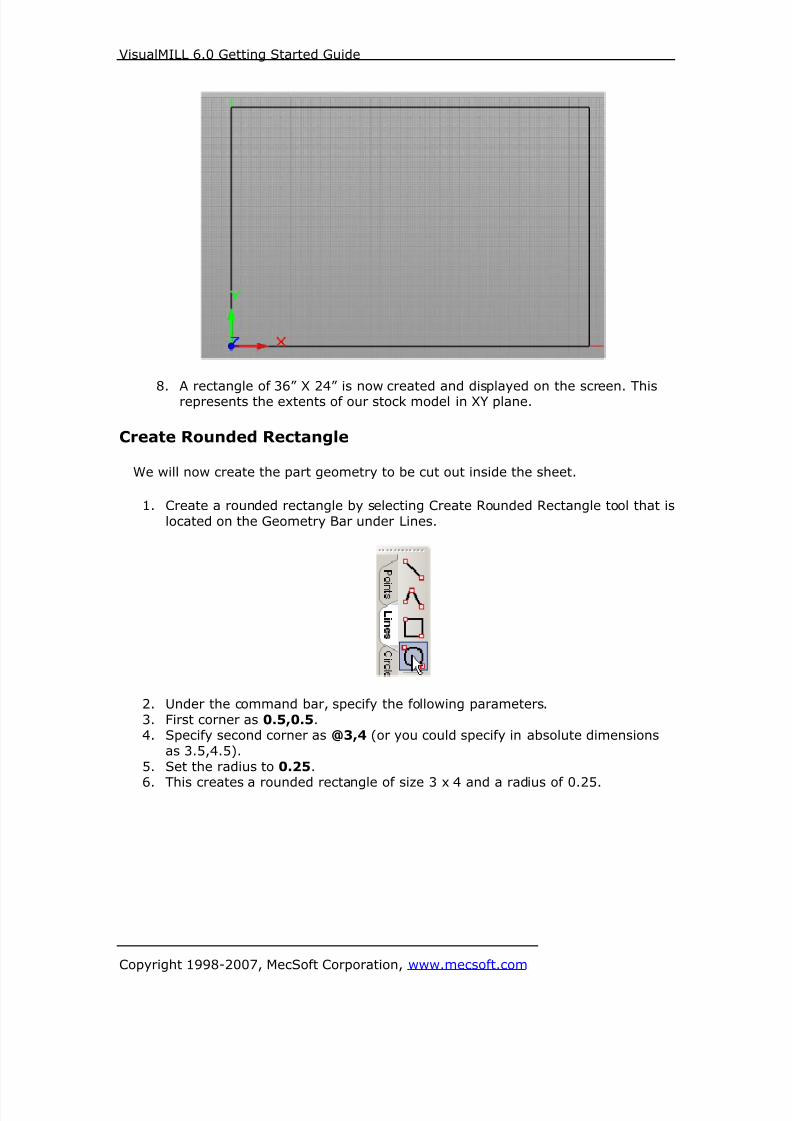
8/16/2019 Visual Mill Getting Started Guide
http://slidepdf.com/reader/full/visual-mill-getting-started-guide 233/411
VisualMILL 6.0 Getting Started Guide
Copyright 1998-2007, MecSoft Corporation, www.mecsoft.com
8. A rectangle of 36” X 24” is now created and displayed on the screen. Thisrepresents the extents of our stock model in XY plane.
Create Rounded Rectangle
We will now create the part geometry to be cut out inside the sheet.
1. Create a rounded rectangle by selecting Create Rounded Rectangle tool that is
located on the Geometry Bar under Lines.
2. Under the command bar, specify the following parameters.
3. First corner as 0.5,0.5.4. Specify second corner as @3,4 (or you could specify in absolute dimensions
as 3.5,4.5).
5. Set the radius to 0.25.
6. This creates a rounded rectangle of size 3 x 4 and a radius of 0.25.
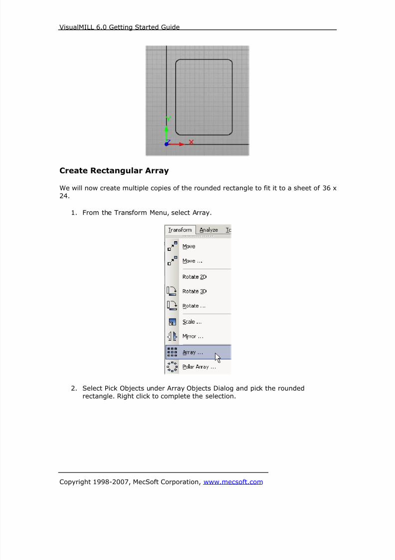
8/16/2019 Visual Mill Getting Started Guide
http://slidepdf.com/reader/full/visual-mill-getting-started-guide 234/411
VisualMILL 6.0 Getting Started Guide
Copyright 1998-2007, MecSoft Corporation, www.mecsoft.com
Create Rectangular Array
We will now create multiple copies of the rounded rectangle to fit it to a sheet of 36 x
24.
1. From the Transform Menu, select Array.
2. Select Pick Objects under Array Objects Dialog and pick the rounded
rectangle. Right click to complete the selection.

8/16/2019 Visual Mill Getting Started Guide
http://slidepdf.com/reader/full/visual-mill-getting-started-guide 235/411
VisualMILL 6.0 Getting Started Guide
Copyright 1998-2007, MecSoft Corporation, www.mecsoft.com
Step 1. Step 2
.
Step3
3. Set the X Spacing = 3.75, Y Spacing = 4.75, and Z Spacing = 0.
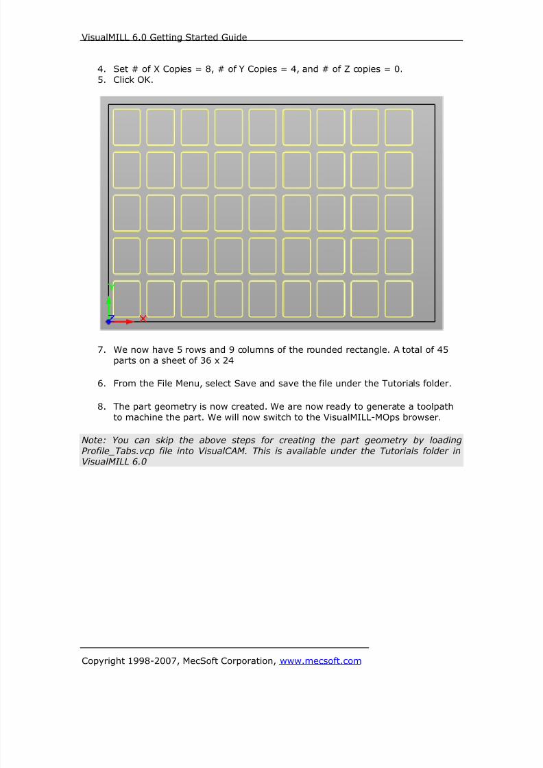
8/16/2019 Visual Mill Getting Started Guide
http://slidepdf.com/reader/full/visual-mill-getting-started-guide 236/411
VisualMILL 6.0 Getting Started Guide
Copyright 1998-2007, MecSoft Corporation, www.mecsoft.com
4. Set # of X Copies = 8, # of Y Copies = 4, and # of Z copies = 0.
5. Click OK.
7. We now have 5 rows and 9 columns of the rounded rectangle. A total of 45
parts on a sheet of 36 x 24
6. From the File Menu, select Save and save the file under the Tutorials folder.
8. The part geometry is now created. We are now ready to generate a toolpathto machine the part. We will now switch to the VisualMILL-MOps browser.
Note: You can skip the above steps for creating the part geometry by loading
Profile_Tabs.vcp file into VisualCAM. This is available under the Tutorials folder inVisualMILL 6.0

8/16/2019 Visual Mill Getting Started Guide
http://slidepdf.com/reader/full/visual-mill-getting-started-guide 237/411
VisualMILL 6.0 Getting Started Guide
Copyright 1998-2007, MecSoft Corporation, www.mecsoft.com
Setup Tab
1. Go to the VisualMILL- MOps browser and click on the Setup tab.
2. Select Machine Setup from the setup tab.
3. Set the Machine type to 3 axis.

8/16/2019 Visual Mill Getting Started Guide
http://slidepdf.com/reader/full/visual-mill-getting-started-guide 238/411
VisualMILL 6.0 Getting Started Guide
Copyright 1998-2007, MecSoft Corporation, www.mecsoft.com
4. Select Post from the setup tab to specify the post processor options.
5. Set the current post processor that is on your controller. We will select Haasas the post processor for this exercise.
Note: By default post processor files are located under
C:\Program Files\MecSoft Corporation\VisualCAM 1.0\Plug-ins\VisualMill 6.0\Posts
The program to send the posted output is set to notepad. This would output the G
code to a notepad.

8/16/2019 Visual Mill Getting Started Guide
http://slidepdf.com/reader/full/visual-mill-getting-started-guide 239/411
VisualMILL 6.0 Getting Started Guide
Copyright 1998-2007, MecSoft Corporation, www.mecsoft.com
Create Stock Geometry
1. Select Create/Load stock from the setup tab and create a Box Stock.
2. This brings up the Box Stock parameters. Set the Length (L) = 36, Width W
= 24, and Height (H) = 0. 5. Make sure to set the corner position toSouthwest corner Top of Stock as shown below.
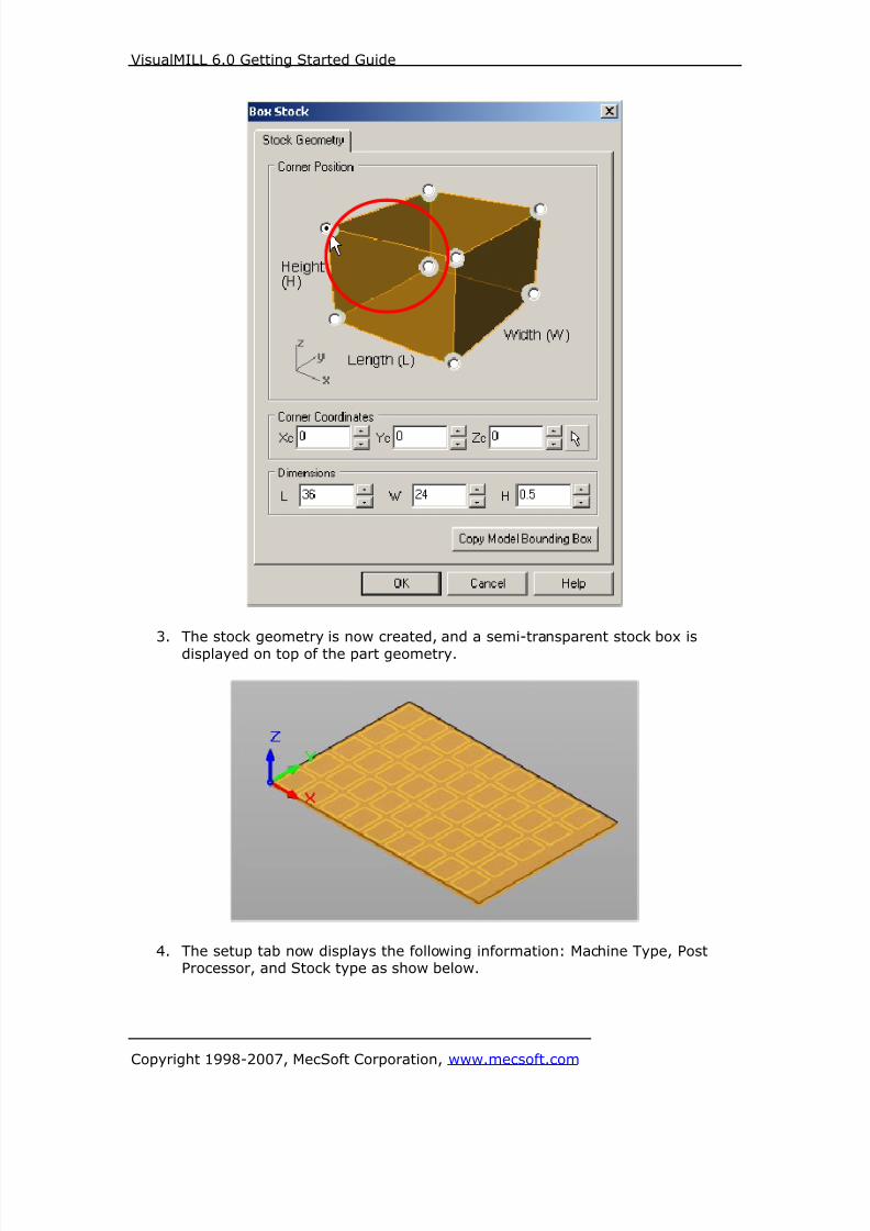
8/16/2019 Visual Mill Getting Started Guide
http://slidepdf.com/reader/full/visual-mill-getting-started-guide 240/411
VisualMILL 6.0 Getting Started Guide
Copyright 1998-2007, MecSoft Corporation, www.mecsoft.com
3. The stock geometry is now created, and a semi-transparent stock box is
displayed on top of the part geometry.
4. The setup tab now displays the following information: Machine Type, PostProcessor, and Stock type as show below.

8/16/2019 Visual Mill Getting Started Guide
http://slidepdf.com/reader/full/visual-mill-getting-started-guide 241/411
VisualMILL 6.0 Getting Started Guide
Copyright 1998-2007, MecSoft Corporation, www.mecsoft.com
Locate Machine Zero
1. The steps below help you determine the machine home (also know as
machine zero or tool touch off point) for the part/stock geometry.2. Select Locate WCS from the Setup tab.
3. Under Set WCS Origin, choose Set to Stock Box, the Zero Face to Highest
Z, and Zero Position to South West corner. This sets the machine home tothe top of the stock material and the southwest corner of the part geometry.

8/16/2019 Visual Mill Getting Started Guide
http://slidepdf.com/reader/full/visual-mill-getting-started-guide 242/411
VisualMILL 6.0 Getting Started Guide
Copyright 1998-2007, MecSoft Corporation, www.mecsoft.com
Note: You can change the stock model transparency under standard mode byselecting Simulation Preferences that is located at the bottom of the MOps browser.

8/16/2019 Visual Mill Getting Started Guide
http://slidepdf.com/reader/full/visual-mill-getting-started-guide 243/411
VisualMILL 6.0 Getting Started Guide
Copyright 1998-2007, MecSoft Corporation, www.mecsoft.com
Align Part and Stock
In this process, we can align the part and the stock geometry. As we have set the
Machine zero to the Stock Box, we will now move the part relative to the stock.
1. Select Align Part and Stock from the Setup tab.
2. Set Object to Move as Move Part, Z alignment as Top, and XY alignment asCenter.

8/16/2019 Visual Mill Getting Started Guide
http://slidepdf.com/reader/full/visual-mill-getting-started-guide 244/411
VisualMILL 6.0 Getting Started Guide
Copyright 1998-2007, MecSoft Corporation, www.mecsoft.com
The part geometry is aligned to the center of stock in XY and top in Z. Click Save
to save the work and specify a file name. The file is now saved with extension
vcp. (VisualCAM Part File)
Create Tools
To machine the above part, we will now create a ¼ inch (0.25”) Flat End Mill.
1. Go to the VisualMILL-Tools browser that is located below the VisualMILL-MOps
browser and select Create/Edit Tools. Select the Tool Type to Flat End Mill.
2. Set the tool name as FlatMill-0.25 and Tool Diameter = 0.25. Under the
Properties tab, set Tool Number = 1.

8/16/2019 Visual Mill Getting Started Guide
http://slidepdf.com/reader/full/visual-mill-getting-started-guide 245/411
VisualMILL 6.0 Getting Started Guide
Copyright 1998-2007, MecSoft Corporation, www.mecsoft.com
Setting Feeds and Speeds
You can assign Feeds & Speeds to a tool or you can load from a table. In this
exercise, we will assign feeds and speeds to the tool.
3. Switch to the Feeds & Speeds tab inside the create/select tool dialog.
4. Use the following settings for feeds and speeds.
5. Click Save as New Tool. The tool is now created and listed under Tools inLibrary. Click OK to close the dialog.
Note: You can edit the tool properties and click Save Edits to Tool to save the
changes. You can create additional tools by assigning a different name and specify
the tool parameters.
The created tools are now listed under the VisualMILL-Tools browser.
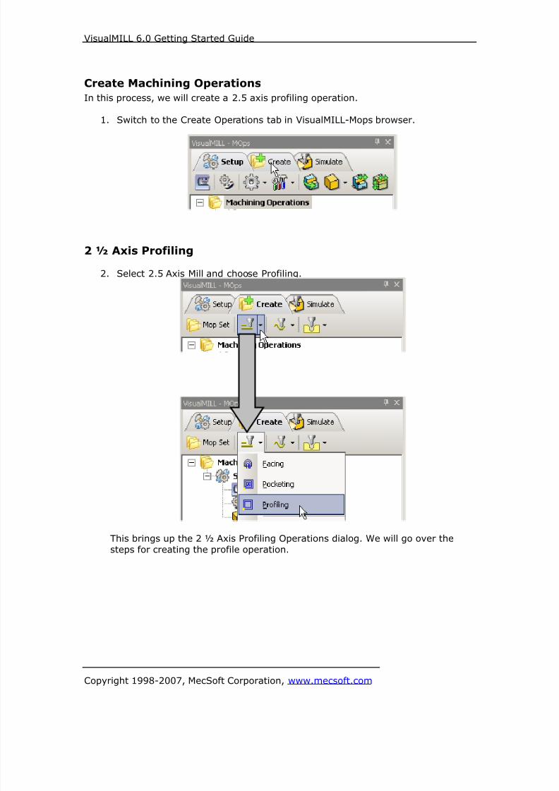
8/16/2019 Visual Mill Getting Started Guide
http://slidepdf.com/reader/full/visual-mill-getting-started-guide 246/411
VisualMILL 6.0 Getting Started Guide
Copyright 1998-2007, MecSoft Corporation, www.mecsoft.com
Create Machining Operations
In this process, we will create a 2.5 axis profiling operation.
1. Switch to the Create Operations tab in VisualMILL-Mops browser.
2 ½ Axis Profiling
2. Select 2.5 Axis Mill and choose Profiling.
This brings up the 2 ½ Axis Profiling Operations dialog. We will go over the
steps for creating the profile operation.
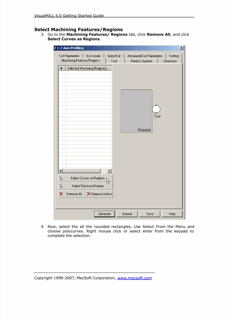
8/16/2019 Visual Mill Getting Started Guide
http://slidepdf.com/reader/full/visual-mill-getting-started-guide 247/411
VisualMILL 6.0 Getting Started Guide
Copyright 1998-2007, MecSoft Corporation, www.mecsoft.com
Select Machining Features/Regions3. Go to the Machining Features/ Regions tab, click Remove All, and click
Select Curves as Regions.
4. Now, select the all the rounded rectangles. Use Select From the Menu andchoose polycurves. Right mouse click or select enter from the keypad tocomplete the selection.

8/16/2019 Visual Mill Getting Started Guide
http://slidepdf.com/reader/full/visual-mill-getting-started-guide 248/411
VisualMILL 6.0 Getting Started Guide
Copyright 1998-2007, MecSoft Corporation, www.mecsoft.com
5. The selected regions are now displayed under Machining Regions.

8/16/2019 Visual Mill Getting Started Guide
http://slidepdf.com/reader/full/visual-mill-getting-started-guide 249/411
VisualMILL 6.0 Getting Started Guide
Copyright 1998-2007, MecSoft Corporation, www.mecsoft.com
Selecting the Tool
6. Switch to the Tools tab inside the 2 ½ Axis Profiling operation.
7. Select the FlatMill-0.25. The 0.25” Flat End mill is now selected as the activetool and the Tool parameters are displayed to the right of the Tools window.

8/16/2019 Visual Mill Getting Started Guide
http://slidepdf.com/reader/full/visual-mill-getting-started-guide 250/411
VisualMILL 6.0 Getting Started Guide
Copyright 1998-2007, MecSoft Corporation, www.mecsoft.com
Set Feeds and Speeds8. Click on the Feeds and Speeds tab.
9. Select Load From Tool. VisualMILL will now get the feeds and speeds
information that was set when the tool was defined.

8/16/2019 Visual Mill Getting Started Guide
http://slidepdf.com/reader/full/visual-mill-getting-started-guide 251/411
VisualMILL 6.0 Getting Started Guide
Copyright 1998-2007, MecSoft Corporation, www.mecsoft.com
Clearance Control10. Switch to Clearance Tab.
11. Set the Clearance Plane Definition to Automatic and Cut Transfer Method to
Clearance Plane.
VisualMILL will determine a safe Z height for the Entry & Exit when set toautomatic. Setting Cut Transfer to Clearance Plane would apply the automatic
Z clearance between transfers when the tool moves from a machining region to
another.

8/16/2019 Visual Mill Getting Started Guide
http://slidepdf.com/reader/full/visual-mill-getting-started-guide 252/411
VisualMILL 6.0 Getting Started Guide
Copyright 1998-2007, MecSoft Corporation, www.mecsoft.com
Specifying Cut Parameters
12. Switch to Cut Parameters tab.
13. Set the Stock = 0. Under Cut Start Side, check Use Outside/Inside forClosed Curves and select Outside.
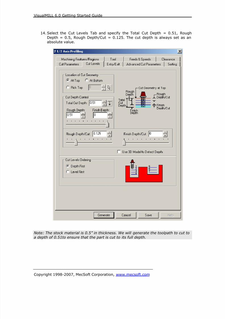
8/16/2019 Visual Mill Getting Started Guide
http://slidepdf.com/reader/full/visual-mill-getting-started-guide 253/411
VisualMILL 6.0 Getting Started Guide
Copyright 1998-2007, MecSoft Corporation, www.mecsoft.com
14. Select the Cut Levels Tab and specify the Total Cut Depth = 0.51, Rough
Depth = 0.5, Rough Depth/Cut = 0.125. The cut depth is always set as anabsolute value.
Note: The stock material is 0.5” in thickness. We will generate the toolpath to cut toa depth of 0.51to ensure that the part is cut to its full depth.
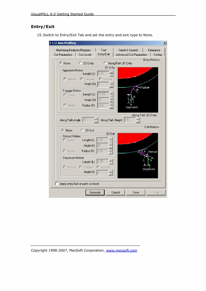
8/16/2019 Visual Mill Getting Started Guide
http://slidepdf.com/reader/full/visual-mill-getting-started-guide 254/411
VisualMILL 6.0 Getting Started Guide
Copyright 1998-2007, MecSoft Corporation, www.mecsoft.com
Entry/Exit
15. Switch to Entry/Exit Tab and set the entry and exit type to None.

8/16/2019 Visual Mill Getting Started Guide
http://slidepdf.com/reader/full/visual-mill-getting-started-guide 255/411
VisualMILL 6.0 Getting Started Guide
Copyright 1998-2007, MecSoft Corporation, www.mecsoft.com
Advanced Cut Parameters
16. Switch to Advanced Cut parameters tab and check Use Bridges/Tabs.
17. Specify bridge height = 0.1, bridge length = 0.6, and # of Bridges on eachpart = 4.
In the next step, we will sort the order of machining the parts.

8/16/2019 Visual Mill Getting Started Guide
http://slidepdf.com/reader/full/visual-mill-getting-started-guide 256/411
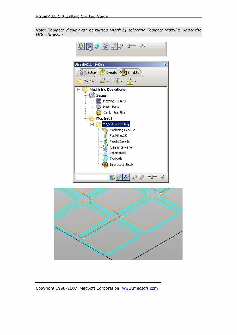
8/16/2019 Visual Mill Getting Started Guide
http://slidepdf.com/reader/full/visual-mill-getting-started-guide 257/411
VisualMILL 6.0 Getting Started Guide
Copyright 1998-2007, MecSoft Corporation, www.mecsoft.com
Note: Toolpath display can be turned on/off by selecting Toolpath Visibility under the
MOps browser.
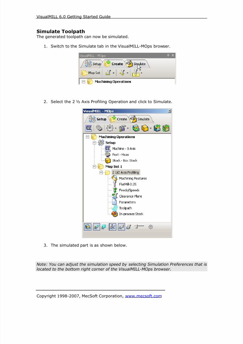
8/16/2019 Visual Mill Getting Started Guide
http://slidepdf.com/reader/full/visual-mill-getting-started-guide 258/411
VisualMILL 6.0 Getting Started Guide
Copyright 1998-2007, MecSoft Corporation, www.mecsoft.com
Simulate ToolpathThe generated toolpath can now be simulated.
1. Switch to the Simulate tab in the VisualMILL-MOps browser.
2. Select the 2 ½ Axis Profiling Operation and click to Simulate.
3. The simulated part is as shown below.
Note: You can adjust the simulation speed by selecting Simulation Preferences that is
located to the bottom right corner of the VisualMILL-MOps browser.

8/16/2019 Visual Mill Getting Started Guide
http://slidepdf.com/reader/full/visual-mill-getting-started-guide 259/411
VisualMILL 6.0 Getting Started Guide
Copyright 1998-2007, MecSoft Corporation, www.mecsoft.com
To exit the Simulation mode, pause the Simulation, and click Exit Simulation. This
switches back to the Create Operations tab.
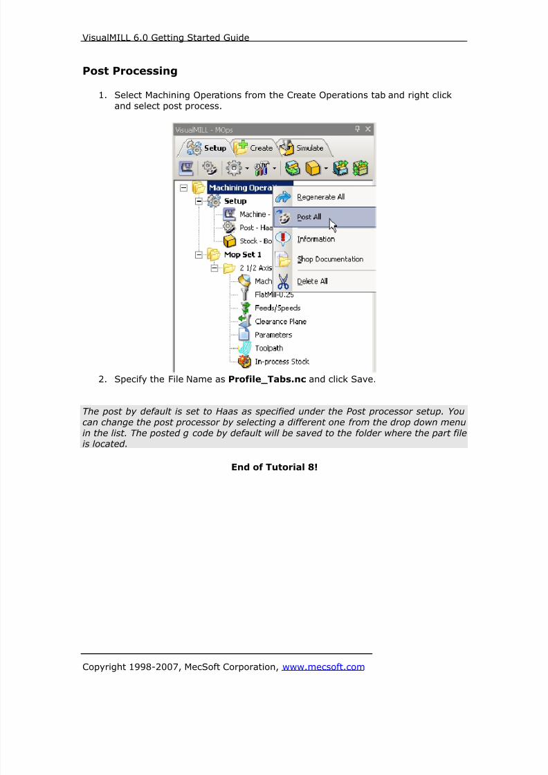
8/16/2019 Visual Mill Getting Started Guide
http://slidepdf.com/reader/full/visual-mill-getting-started-guide 260/411
VisualMILL 6.0 Getting Started Guide
Copyright 1998-2007, MecSoft Corporation, www.mecsoft.com
Post Processing
1. Select Machining Operations from the Create Operations tab and right click
and select post process.
2. Specify the File Name as Profile_Tabs.nc and click Save.
The post by default is set to Haas as specified under the Post processor setup. You
can change the post processor by selecting a different one from the drop down menu
in the list. The posted g code by default will be saved to the folder where the part fileis located.
End of Tutorial 8!

8/16/2019 Visual Mill Getting Started Guide
http://slidepdf.com/reader/full/visual-mill-getting-started-guide 261/411
VisualMILL 6.0 Getting Started Guide
Copyright 1998-2007, MecSoft Corporation, www.mecsoft.com
Tutorial 9: Hole Making

8/16/2019 Visual Mill Getting Started Guide
http://slidepdf.com/reader/full/visual-mill-getting-started-guide 262/411
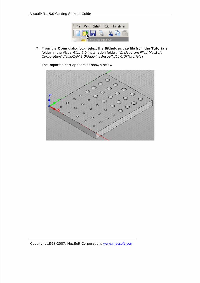
8/16/2019 Visual Mill Getting Started Guide
http://slidepdf.com/reader/full/visual-mill-getting-started-guide 263/411
VisualMILL 6.0 Getting Started Guide
Copyright 1998-2007, MecSoft Corporation, www.mecsoft.com
2. From the Open dialog box, select the Bitholder.vcp file from the Tutorials folder in the VisualMILL 6.0 installation folder. (C:\Program Files\MecSoft
Corporation\VisualCAM 1.0\Plug-ins\VisualMILL 6.0\Tutorials)
The imported part appears as shown below

8/16/2019 Visual Mill Getting Started Guide
http://slidepdf.com/reader/full/visual-mill-getting-started-guide 264/411
VisualMILL 6.0 Getting Started Guide
Copyright 1998-2007, MecSoft Corporation, www.mecsoft.com
Setup Tab
1. Go to the VisualMILL- MOps browser and click on the Setup tab.
2. Select Machine Setup from the setup tab.
3. Set the Machine type to 3 axis.

8/16/2019 Visual Mill Getting Started Guide
http://slidepdf.com/reader/full/visual-mill-getting-started-guide 265/411
VisualMILL 6.0 Getting Started Guide
Copyright 1998-2007, MecSoft Corporation, www.mecsoft.com
4. Select Post from the setup tab to specify the post processor options.
5. Set the current post processor that is on your controller. We will select Haas
as the post processor for this exercise. Set the posted file extension type to
.nc
Note: By default post processor files are located under
C:\Program Files\MecSoft Corporation\VisualCAM 1.0\Plug-ins\VisualMill 6.0\Posts
The program to send the posted output is set to notepad. This would output the G
code to a notepad.

8/16/2019 Visual Mill Getting Started Guide
http://slidepdf.com/reader/full/visual-mill-getting-started-guide 266/411
VisualMILL 6.0 Getting Started Guide
Copyright 1998-2007, MecSoft Corporation, www.mecsoft.com
Create Stock Geometry
1. Select Create/Load stock from the setup tab and create a Box Stock.
2. This brings up the Box Stock parameters. Set the Length (L) = 7.00, WidthW = 8.50, and Height (H) = 0.75. Leave the other parameters as default and
Click OK.

8/16/2019 Visual Mill Getting Started Guide
http://slidepdf.com/reader/full/visual-mill-getting-started-guide 267/411
VisualMILL 6.0 Getting Started Guide
Copyright 1998-2007, MecSoft Corporation, www.mecsoft.com
3. The stock geometry is now created, and a semi-transparent stock box isdisplayed on top of the part geometry.
4. The setup tab now displays the following information: Machine Type, PostProcessor, and Stock type as show below.

8/16/2019 Visual Mill Getting Started Guide
http://slidepdf.com/reader/full/visual-mill-getting-started-guide 268/411
VisualMILL 6.0 Getting Started Guide
Copyright 1998-2007, MecSoft Corporation, www.mecsoft.com
Locate Machine Zero
1. The steps below help you determine the machine home (also know as
machine zero or tool touch off point) for the part/stock geometry.2. Select Locate WCS from the Setup tab.
3. Under Set WCS Origin, choose Set to Stock Box, the Zero Face to Highest Z
and Zero Position to South West corner. This sets the machine home to thetop of the stock material and the southwest corner of the part geometry.
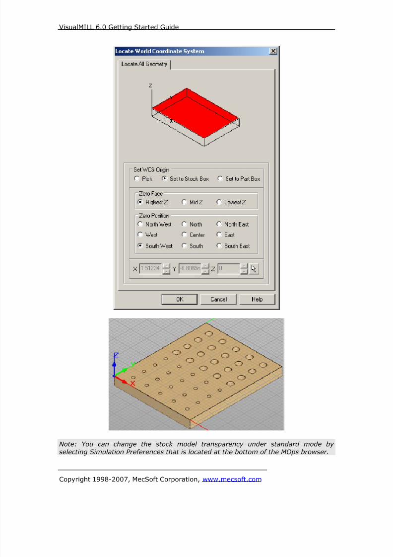
8/16/2019 Visual Mill Getting Started Guide
http://slidepdf.com/reader/full/visual-mill-getting-started-guide 269/411
VisualMILL 6.0 Getting Started Guide
Copyright 1998-2007, MecSoft Corporation, www.mecsoft.com
Note: You can change the stock model transparency under standard mode by
selecting Simulation Preferences that is located at the bottom of the MOps browser.

8/16/2019 Visual Mill Getting Started Guide
http://slidepdf.com/reader/full/visual-mill-getting-started-guide 270/411
VisualMILL 6.0 Getting Started Guide
Copyright 1998-2007, MecSoft Corporation, www.mecsoft.com
Align Part and Stock
In this process, we can align the part and the stock geometry. As we have set the
Machine zero to the Stock Box, we will now move the part relative to the stock.
1. Select Align Part and Stock from the Setup tab
2. Set to Object to Move as Move Part, Z alignment as Top, and XY alignmentas Center
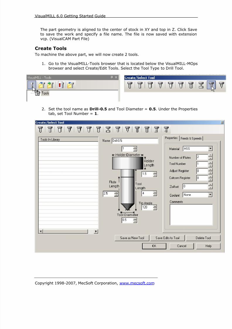
8/16/2019 Visual Mill Getting Started Guide
http://slidepdf.com/reader/full/visual-mill-getting-started-guide 271/411
VisualMILL 6.0 Getting Started Guide
Copyright 1998-2007, MecSoft Corporation, www.mecsoft.com
The part geometry is aligned to the center of stock in XY and top in Z. Click Save
to save the work and specify a file name. The file is now saved with extension
vcp. (VisualCAM Part File)
Create Tools
To machine the above part, we will now create 2 tools.
1. Go to the VisualMILL-Tools browser that is located below the VisualMILL-MOps
browser and select Create/Edit Tools. Select the Tool Type to Drill Tool.
2. Set the tool name as Drill-0.5 and Tool Diameter = 0.5. Under the Properties
tab, set Tool Number = 1.

8/16/2019 Visual Mill Getting Started Guide
http://slidepdf.com/reader/full/visual-mill-getting-started-guide 272/411

8/16/2019 Visual Mill Getting Started Guide
http://slidepdf.com/reader/full/visual-mill-getting-started-guide 273/411
VisualMILL 6.0 Getting Started Guide
Copyright 1998-2007, MecSoft Corporation, www.mecsoft.com
Create/Extract Regions
In order to machine the holes, we need to extract the curves from the 3d model to
select them as machining regions.
1. Select the Layer Manager from the Standard bar
2. The layer manager is now open. Set the Layer01 as the active layer.
3. Close the Layer Manager.
4. From the Curves tab on the Geometry Bar to your right, select Single Flat
Area Regions.
5. The command bar would now prompt the user to select a flat area to extract
the curves.

8/16/2019 Visual Mill Getting Started Guide
http://slidepdf.com/reader/full/visual-mill-getting-started-guide 274/411
VisualMILL 6.0 Getting Started Guide
Copyright 1998-2007, MecSoft Corporation, www.mecsoft.com
6. Select the top face (surface) on the part.
7. The curves are now created and displayed in red on the part geometry.
Note: You can toggle the stock model display by selecting Stock Visibility that is
located at the bottom of the VisualMill-MOps Browser

8/16/2019 Visual Mill Getting Started Guide
http://slidepdf.com/reader/full/visual-mill-getting-started-guide 275/411
VisualMILL 6.0 Getting Started Guide
Copyright 1998-2007, MecSoft Corporation, www.mecsoft.com
Create Machining Operations
In this process, we will create a 2.5 axis profiling operation.
1. Switch to the Create Operations tab in VisualMILL-Mops browser.
Hole Machining
2. Select Hole Machining and choose Drilling.
This brings up the Drilling Operations dialog. We will go over the steps forcreating the toolpath.
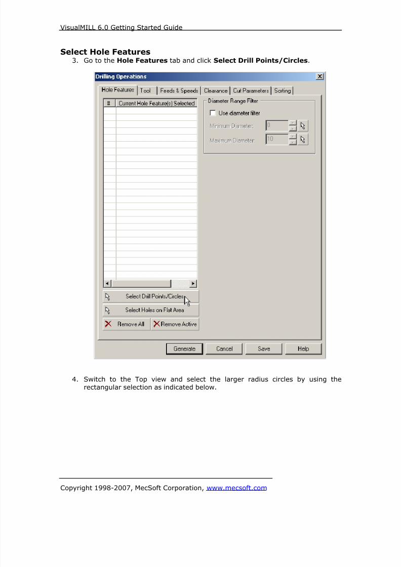
8/16/2019 Visual Mill Getting Started Guide
http://slidepdf.com/reader/full/visual-mill-getting-started-guide 276/411
VisualMILL 6.0 Getting Started Guide
Copyright 1998-2007, MecSoft Corporation, www.mecsoft.com
Select Hole Features3. Go to the Hole Features tab and click Select Drill Points/Circles.
4. Switch to the Top view and select the larger radius circles by using the
rectangular selection as indicated below.
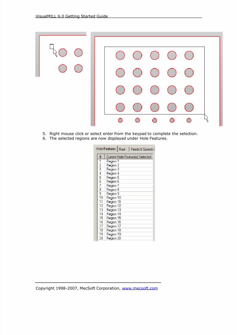
8/16/2019 Visual Mill Getting Started Guide
http://slidepdf.com/reader/full/visual-mill-getting-started-guide 277/411
VisualMILL 6.0 Getting Started Guide
Copyright 1998-2007, MecSoft Corporation, www.mecsoft.com
5. Right mouse click or select enter from the keypad to complete the selection.
6. The selected regions are now displayed under Hole Features.

8/16/2019 Visual Mill Getting Started Guide
http://slidepdf.com/reader/full/visual-mill-getting-started-guide 278/411
VisualMILL 6.0 Getting Started Guide
Copyright 1998-2007, MecSoft Corporation, www.mecsoft.com
Selecting the Tool
7. Switch to the Tools tab inside the Drilling operation.
8. Select the Drill-0.5. The 0.5” Drill is now selected as the active tool and the
Tool parameters are displayed to the right of the Tools window.
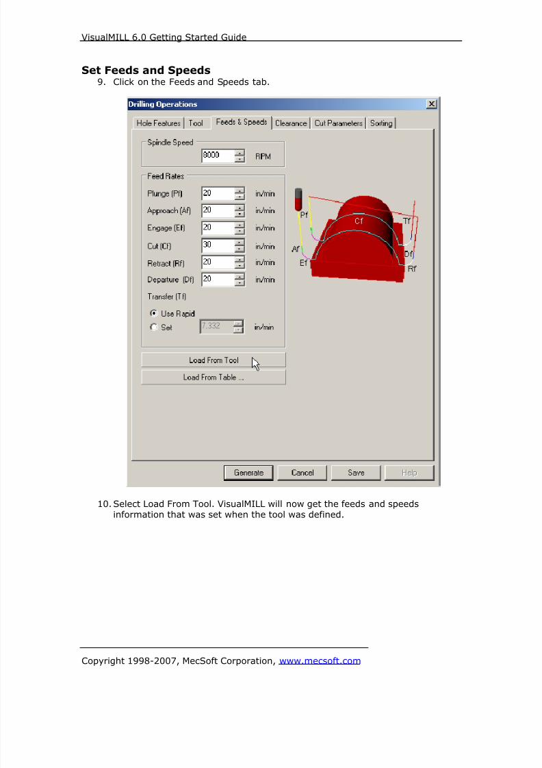
8/16/2019 Visual Mill Getting Started Guide
http://slidepdf.com/reader/full/visual-mill-getting-started-guide 279/411
VisualMILL 6.0 Getting Started Guide
Copyright 1998-2007, MecSoft Corporation, www.mecsoft.com
Set Feeds and Speeds9. Click on the Feeds and Speeds tab.
10. Select Load From Tool. VisualMILL will now get the feeds and speedsinformation that was set when the tool was defined.

8/16/2019 Visual Mill Getting Started Guide
http://slidepdf.com/reader/full/visual-mill-getting-started-guide 280/411
VisualMILL 6.0 Getting Started Guide
Copyright 1998-2007, MecSoft Corporation, www.mecsoft.com
Clearance Control11. Switch to Clearance Tab.
12. Set the Clearance Plane Definition to Automatic and Cut Transfer Method to
Clearance Plane.
VisualMILL will determine a safe Z height for the Entry & Exit when set toautomatic. Setting Cut Transfer to Clearance Plane would apply the automatic
Z clearance between transfers when the tool moves from a machining region to
another.
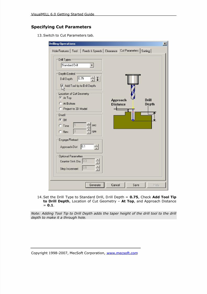
8/16/2019 Visual Mill Getting Started Guide
http://slidepdf.com/reader/full/visual-mill-getting-started-guide 281/411
VisualMILL 6.0 Getting Started Guide
Copyright 1998-2007, MecSoft Corporation, www.mecsoft.com
Specifying Cut Parameters
13. Switch to Cut Parameters tab.
14. Set the Drill Type to Standard Drill, Drill Depth = 0.75, Check Add Tool Tip
to Drill Depth, Location of Cut Geometry – At Top, and Approach Distance
= 0.1.
Note: Adding Tool Tip to Drill Depth adds the taper height of the drill tool to the drill
depth to make it a through hole.
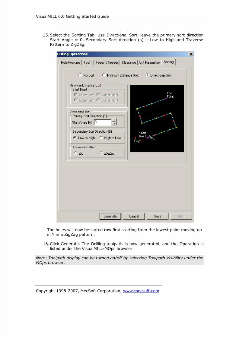
8/16/2019 Visual Mill Getting Started Guide
http://slidepdf.com/reader/full/visual-mill-getting-started-guide 282/411
VisualMILL 6.0 Getting Started Guide
Copyright 1998-2007, MecSoft Corporation, www.mecsoft.com
15. Select the Sorting Tab. Use Directional Sort, leave the primary sort direction
Start Angle = 0, Secondary Sort direction (s) – Low to High and TraversePattern to ZigZag.
The holes will now be sorted row first starting from the lowest point moving up
in Y in a ZigZag pattern.
16. Click Generate. The Drilling toolpath is now generated, and the Operation is
listed under the VisualMILL-MOps browser.
Note: Toolpath display can be turned on/off by selecting Toolpath Visibility under the
MOps browser.
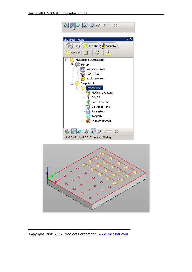
8/16/2019 Visual Mill Getting Started Guide
http://slidepdf.com/reader/full/visual-mill-getting-started-guide 283/411
VisualMILL 6.0 Getting Started Guide
Copyright 1998-2007, MecSoft Corporation, www.mecsoft.com

8/16/2019 Visual Mill Getting Started Guide
http://slidepdf.com/reader/full/visual-mill-getting-started-guide 284/411
VisualMILL 6.0 Getting Started Guide
Copyright 1998-2007, MecSoft Corporation, www.mecsoft.com
Simulate ToolpathThe generated toolpath can now be simulated.
1. Switch to the Simulate tab in the VisualMILL-MOps browser.
2. Select the 2 ½ Axis Profiling Operation and click to Simulate.
3. The simulated part is as shown below.
Note: You can adjust the simulation speed by selecting Simulation Preferences that islocated to the bottom right corner of the VisualMILL-MOps browser.
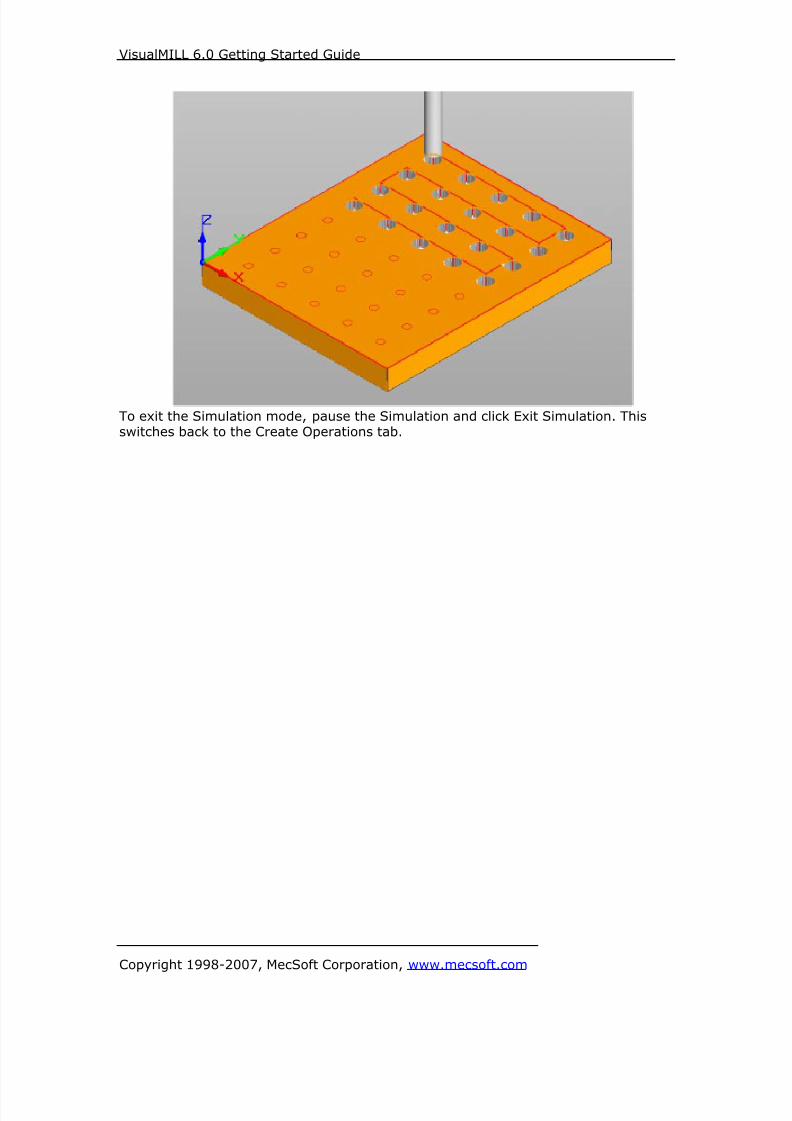
8/16/2019 Visual Mill Getting Started Guide
http://slidepdf.com/reader/full/visual-mill-getting-started-guide 285/411
VisualMILL 6.0 Getting Started Guide
Copyright 1998-2007, MecSoft Corporation, www.mecsoft.com
To exit the Simulation mode, pause the Simulation and click Exit Simulation. Thisswitches back to the Create Operations tab.
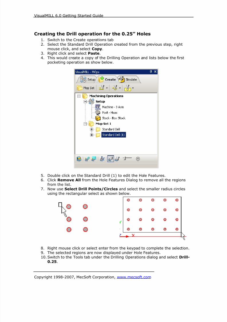
8/16/2019 Visual Mill Getting Started Guide
http://slidepdf.com/reader/full/visual-mill-getting-started-guide 286/411
VisualMILL 6.0 Getting Started Guide
Copyright 1998-2007, MecSoft Corporation, www.mecsoft.com
Creating the Drill operation for the 0.25” Holes
1. Switch to the Create operations tab
2. Select the Standard Drill Operation created from the previous step, right
mouse click, and select Copy.3. Right click and select Paste.
4. This would create a copy of the Drilling Operation and lists below the firstpocketing operation as show below.
5. Double click on the Standard Drill (1) to edit the Hole Features.6. Click Remove All from the Hole Features Dialog to remove all the regions
from the list.7. Now use Select Drill Points/Circles and select the smaller radius circles
using the rectangular select as shown below.
8. Right mouse click or select enter from the keypad to complete the selection.
9. The selected regions are now displayed under Hole Features.10. Switch to the Tools tab under the Drilling Operations dialog and select Drill-
0.25.
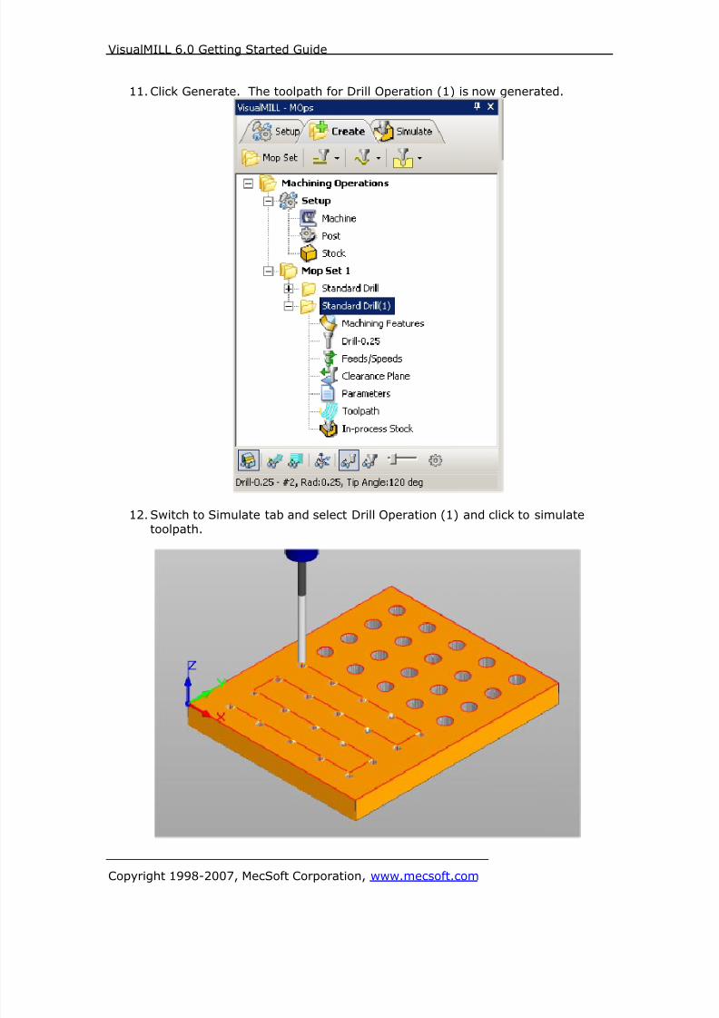
8/16/2019 Visual Mill Getting Started Guide
http://slidepdf.com/reader/full/visual-mill-getting-started-guide 287/411
VisualMILL 6.0 Getting Started Guide
Copyright 1998-2007, MecSoft Corporation, www.mecsoft.com
11. Click Generate. The toolpath for Drill Operation (1) is now generated.
12. Switch to Simulate tab and select Drill Operation (1) and click to simulate
toolpath.
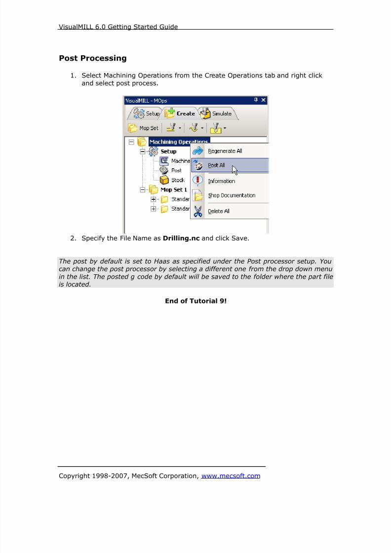
8/16/2019 Visual Mill Getting Started Guide
http://slidepdf.com/reader/full/visual-mill-getting-started-guide 288/411
VisualMILL 6.0 Getting Started Guide
Copyright 1998-2007, MecSoft Corporation, www.mecsoft.com
Post Processing
1. Select Machining Operations from the Create Operations tab and right click
and select post process.
2. Specify the File Name as Drilling.nc and click Save.
The post by default is set to Haas as specified under the Post processor setup. Youcan change the post processor by selecting a different one from the drop down menu
in the list. The posted g code by default will be saved to the folder where the part fileis located.
End of Tutorial 9!

8/16/2019 Visual Mill Getting Started Guide
http://slidepdf.com/reader/full/visual-mill-getting-started-guide 289/411
VisualMILL 6.0 Getting Started Guide
Copyright 1998-2007, MecSoft Corporation, www.mecsoft.com
Tutorial 10: Machining a Ring

8/16/2019 Visual Mill Getting Started Guide
http://slidepdf.com/reader/full/visual-mill-getting-started-guide 290/411
VisualMILL 6.0 Getting Started Guide
Copyright 1998-2007, MecSoft Corporation, www.mecsoft.com
Introduction
This tutorial will illustrate machining this Ring using 4 axis-milling operations.
This tutorial will introduce the usage of several 4-axis operations such as 4 axis
roughing and finishing.The stepped instructions are accompanied by explanatory and introductory text.
Reading this text will help you understand the tutorial methodology and provideinformation about additional options available.
Don’t forget to save your work periodically! You may want to save the file under a
different name so that the original file will be preserved.
Strategy to Machine the ring
• We will machine the ring completely using 4 axis-machining operations.
• The part itself will be machined out of a cylindrical blank.
• The stock will be held to the machine table using a rotary chuck.
• The part will be machined using 0.125” and 0.0625” ball end mills.
Main Programming StepsIn creating programs for each setup, the following steps will be followed:
• Create the Stock geometry
• Set the Machine zero point or Locate geometry with respect to the machine
coordinates.
• Set the rotary axis and rotary center.
• Create / Select the tool used for machining
• Set the feeds and speeds
• Set the clearance plane for the non-cutting transfer moves of the cutter
• Select the machining operations and set the parameters
• Generate the toolpath• Simulate the toolpath.
You may have to repeat either all or part of these steps for subsequent operations.
Preparing the part for Machining
Loading the Part Model “Part” refers to the geometry that represents the final manufactured product. Youcan create parts within VisualMILL, but it is more typical to import geometry created
in another CAD system.
To load a part:
1. Select File / Open from the Menu, or click the Open icon from the Standard
bar.2. From the Open dialog box, select the RingExample_1.vcp file from the
Tutorials folder in the VisualMILL 6.0 installation folder. (C:\ProgramFiles\MecSoft Corporation\VisualCAM 1.0\Plug-ins\VisualMILL 6.0\Tutorials)
The imported part appears as shown below

8/16/2019 Visual Mill Getting Started Guide
http://slidepdf.com/reader/full/visual-mill-getting-started-guide 291/411
VisualMILL 6.0 Getting Started Guide
Copyright 1998-2007, MecSoft Corporation, www.mecsoft.com
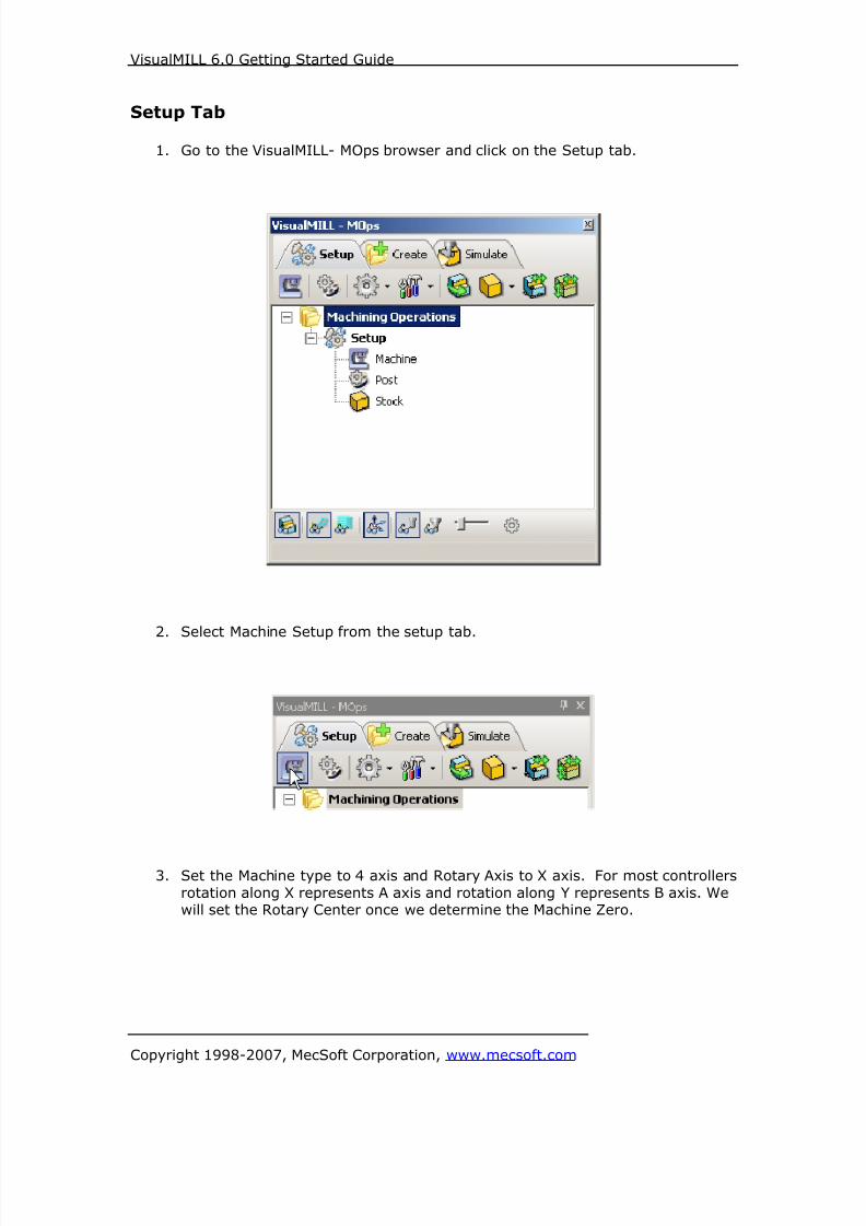
8/16/2019 Visual Mill Getting Started Guide
http://slidepdf.com/reader/full/visual-mill-getting-started-guide 292/411
VisualMILL 6.0 Getting Started Guide
Copyright 1998-2007, MecSoft Corporation, www.mecsoft.com
Setup Tab
1. Go to the VisualMILL- MOps browser and click on the Setup tab.
2. Select Machine Setup from the setup tab.
3. Set the Machine type to 4 axis and Rotary Axis to X axis. For most controllers
rotation along X represents A axis and rotation along Y represents B axis. Wewill set the Rotary Center once we determine the Machine Zero.

8/16/2019 Visual Mill Getting Started Guide
http://slidepdf.com/reader/full/visual-mill-getting-started-guide 293/411
VisualMILL 6.0 Getting Started Guide
Copyright 1998-2007, MecSoft Corporation, www.mecsoft.com
4. Select Post from the setup tab to specify the post processor options.
5. Set the current post processor that is on your controller. We will select Haasas the post processor for this exercise.
Note: By default post processor files are located under
C:\Program Files\MecSoft Corporation\VisualCAM 1.0\Plug-ins\VisualMill 6.0\Posts
The program to send the posted output is set to notepad. This would output the Gcode to a notepad.

8/16/2019 Visual Mill Getting Started Guide
http://slidepdf.com/reader/full/visual-mill-getting-started-guide 294/411
VisualMILL 6.0 Getting Started Guide
Copyright 1998-2007, MecSoft Corporation, www.mecsoft.com
Create Stock Geometry
1. Select Create/Load stock from the setup tab and create a Cylinder Stock.
2. This brings up the Cylinder Stock parameters. Set the Axis (rotary) = X,
Radius = 0.56” and Length (L) = 0.866142. Leave the other parameters as
default and click OK.

8/16/2019 Visual Mill Getting Started Guide
http://slidepdf.com/reader/full/visual-mill-getting-started-guide 295/411
VisualMILL 6.0 Getting Started Guide
Copyright 1998-2007, MecSoft Corporation, www.mecsoft.com
3. The stock geometry is now created, and a semi-transparent stock is displayedon top of the part geometry.
Isometric View Front View

8/16/2019 Visual Mill Getting Started Guide
http://slidepdf.com/reader/full/visual-mill-getting-started-guide 296/411
VisualMILL 6.0 Getting Started Guide
Copyright 1998-2007, MecSoft Corporation, www.mecsoft.com
4. You must switch the simulation model to Polygonal model to run 4 axis
simulations. Select Preferences->Simulation Preferences from the Setup Tab
and switch the simulation model to Polygonal if set to Voxel.

8/16/2019 Visual Mill Getting Started Guide
http://slidepdf.com/reader/full/visual-mill-getting-started-guide 297/411
VisualMILL 6.0 Getting Started Guide
Copyright 1998-2007, MecSoft Corporation, www.mecsoft.com
5. The setup tab now displays the following information: Machine Type, Post
Processor, and Stock type as show below.
Locate Machine Zero
1. The steps below help you determine the machine home (also know as
machine zero or tool touch off point) for the part/stock geometry.
2. Select Locate WCS from the Setup tab.
3. Under Set WCS Origin, choose Set to Stock Box, the Zero Face to Highest
Z, and Zero Position to East. This sets the machine home to the top of thestock material and the right most edge of the part geometry.
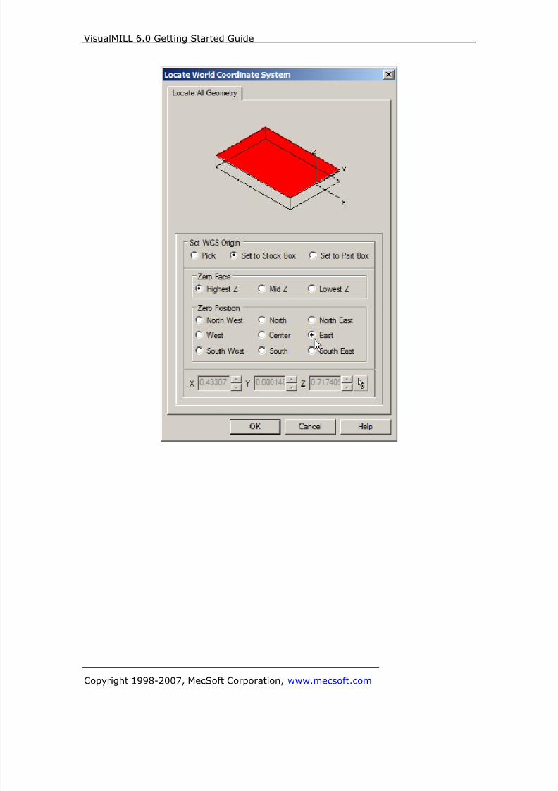
8/16/2019 Visual Mill Getting Started Guide
http://slidepdf.com/reader/full/visual-mill-getting-started-guide 298/411
VisualMILL 6.0 Getting Started Guide
Copyright 1998-2007, MecSoft Corporation, www.mecsoft.com
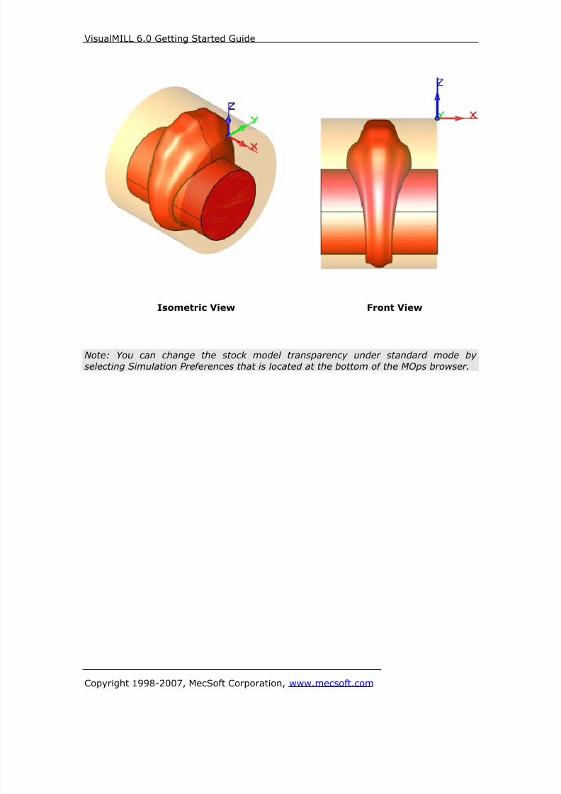
8/16/2019 Visual Mill Getting Started Guide
http://slidepdf.com/reader/full/visual-mill-getting-started-guide 299/411
VisualMILL 6.0 Getting Started Guide
Copyright 1998-2007, MecSoft Corporation, www.mecsoft.com
Isometric View Front View
Note: You can change the stock model transparency under standard mode by
selecting Simulation Preferences that is located at the bottom of the MOps browser.
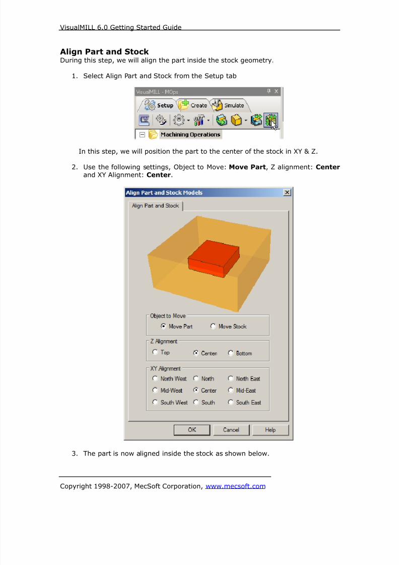
8/16/2019 Visual Mill Getting Started Guide
http://slidepdf.com/reader/full/visual-mill-getting-started-guide 300/411
VisualMILL 6.0 Getting Started Guide
Copyright 1998-2007, MecSoft Corporation, www.mecsoft.com
Align Part and StockDuring this step, we will align the part inside the stock geometry.
1. Select Align Part and Stock from the Setup tab
In this step, we will position the part to the center of the stock in XY & Z.
2. Use the following settings, Object to Move: Move Part, Z alignment: Center and XY Alignment: Center.
3. The part is now aligned inside the stock as shown below.

8/16/2019 Visual Mill Getting Started Guide
http://slidepdf.com/reader/full/visual-mill-getting-started-guide 301/411
VisualMILL 6.0 Getting Started Guide
Copyright 1998-2007, MecSoft Corporation, www.mecsoft.com
Isometric View Front View
Specify Rotary CenterIn this step we will determine the rotary center for the part geometry. The rotarycenter must pass thro’ the entire part geometry. VisualMILL will not compute a
toolpath if the part/feature is below the rotary center as this is considered as anundercuts in the part.
1. Select Machine Setup from the setup tab.
In the above example, the stock diameter is 1.12”.
2. Set the rotary center in X and Y = 0 and Z = -0.56 which is the center of the
stock geometry.
The rotary center is represented by an arrow and displayed on the part geometry
when the Machine Setup Dialog is invoked.

8/16/2019 Visual Mill Getting Started Guide
http://slidepdf.com/reader/full/visual-mill-getting-started-guide 302/411
VisualMILL 6.0 Getting Started Guide
Copyright 1998-2007, MecSoft Corporation, www.mecsoft.com

8/16/2019 Visual Mill Getting Started Guide
http://slidepdf.com/reader/full/visual-mill-getting-started-guide 303/411
VisualMILL 6.0 Getting Started Guide
Copyright 1998-2007, MecSoft Corporation, www.mecsoft.com
Create Tools
To machine the above part, we will now create a 0.125” Ball End Mill and a 0.0625”
Ball End Mill.
1. Go to the VisualMILL-Tools browser that is located below the VisualMILL-MOpsbrowser and select Create/Edit Tools. Select the Tool Type to Ball End Mill.
2. Set the tool name as BallMill-0.125 and Tool Diameter = 0.125. Under the
Properties tab, set Tool Number = 1.

8/16/2019 Visual Mill Getting Started Guide
http://slidepdf.com/reader/full/visual-mill-getting-started-guide 304/411
VisualMILL 6.0 Getting Started Guide
Copyright 1998-2007, MecSoft Corporation, www.mecsoft.com
Setting Feeds and Speeds
You can assign Feeds & Speeds to a tool or you can load from a table. In this
exercise, we will assign feeds and speeds to the tool.
3. Switch to the Feeds & Speeds tab inside the create/select tool dialog.
4. Use the following settings for feeds and speeds.
5. Click Save as New Tool. The tool is now created and listed under Tools inLibrary.
Note: You can edit the tool properties and click Save Edits to Tool to save the
changes. You can create additional tools by assigning a different name and specifythe tool parameters.
6. Create a 2nd Ball End Mill with the following parameters.
a. Tool Name: BallMill-0.0625, Tool Number = 2.
b. Switch to Feeds & Speeds tab set Spindle Speed = 5000 rpm, plunge,approach & engage feed = 20 ipm, cut feed = 30 ipm, retract anddeparture feeds = 20 ipm. Set the Transfer Feedrate to Use Rapid.
c. Click Save as New Tool.
The created tools are now listed under the VisualMILL-Tools browser.
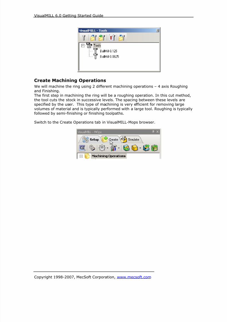
8/16/2019 Visual Mill Getting Started Guide
http://slidepdf.com/reader/full/visual-mill-getting-started-guide 305/411
VisualMILL 6.0 Getting Started Guide
Copyright 1998-2007, MecSoft Corporation, www.mecsoft.com
Create Machining Operations
We will machine the ring using 2 different machining operations – 4 axis Roughing
and Finishing.The first step in machining the ring will be a roughing operation. In this cut method,
the tool cuts the stock in successive levels. The spacing between these levels arespecified by the user. This type of machining is very efficient for removing large
volumes of material and is typically performed with a large tool. Roughing is typically
followed by semi-finishing or finishing toolpaths.
Switch to the Create Operations tab in VisualMILL-Mops browser.

8/16/2019 Visual Mill Getting Started Guide
http://slidepdf.com/reader/full/visual-mill-getting-started-guide 306/411
VisualMILL 6.0 Getting Started Guide
Copyright 1998-2007, MecSoft Corporation, www.mecsoft.com
4 axis Roughing
1. Select 4 Axis Milling and choose Roughing.
If the rotary center is not set to the same location as the Machine Zero, a
warning message dialog would be displayed at all times when a 4 axismachining operation is selected. Users can override this message by clicking
OK in the dialog.
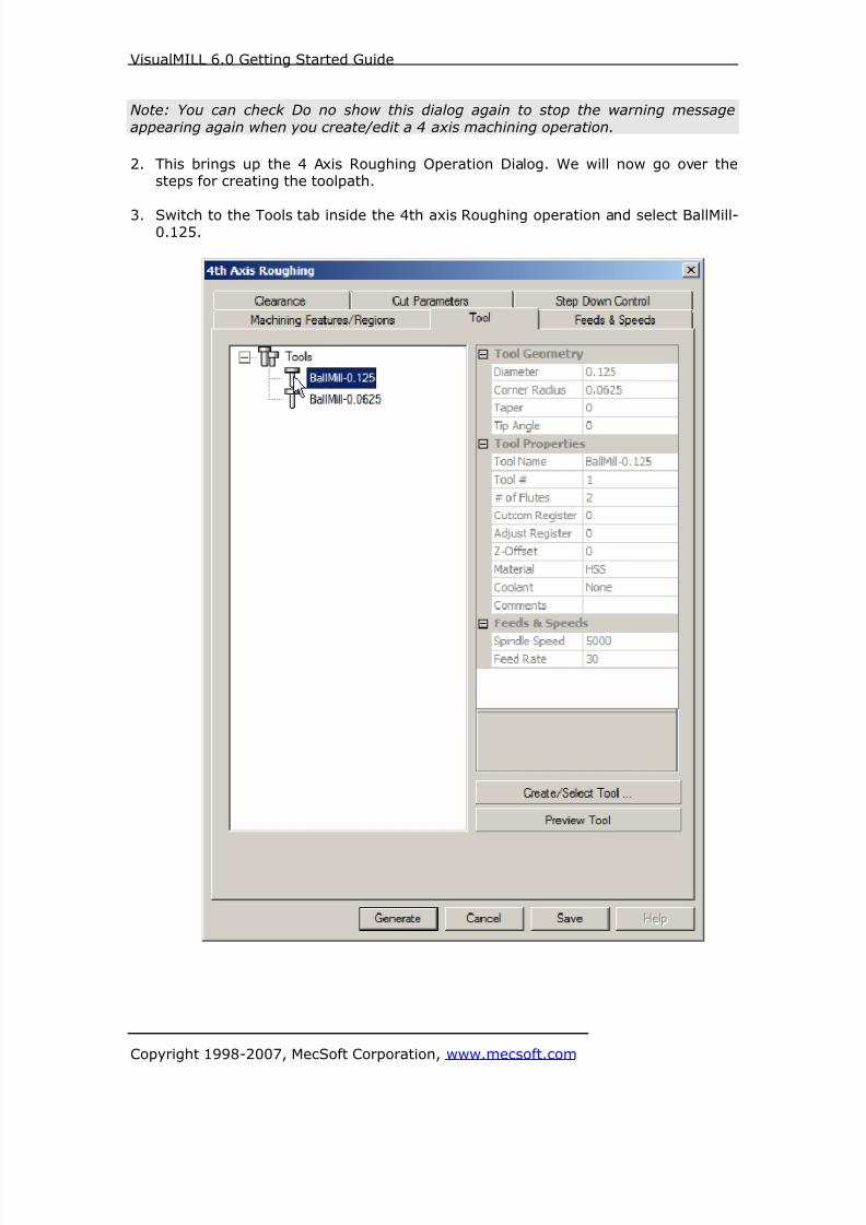
8/16/2019 Visual Mill Getting Started Guide
http://slidepdf.com/reader/full/visual-mill-getting-started-guide 307/411
VisualMILL 6.0 Getting Started Guide
Copyright 1998-2007, MecSoft Corporation, www.mecsoft.com
Note: You can check Do no show this dialog again to stop the warning message
appearing again when you create/edit a 4 axis machining operation.
2. This brings up the 4 Axis Roughing Operation Dialog. We will now go over thesteps for creating the toolpath.
3. Switch to the Tools tab inside the 4th axis Roughing operation and select BallMill-0.125.

8/16/2019 Visual Mill Getting Started Guide
http://slidepdf.com/reader/full/visual-mill-getting-started-guide 308/411
VisualMILL 6.0 Getting Started Guide
Copyright 1998-2007, MecSoft Corporation, www.mecsoft.com
4. Click on the Feeds and Speeds tab and select Load From Tool. VisualMILL will
now get the feeds and speeds information that was set when the tool wasdefined.

8/16/2019 Visual Mill Getting Started Guide
http://slidepdf.com/reader/full/visual-mill-getting-started-guide 309/411
VisualMILL 6.0 Getting Started Guide
Copyright 1998-2007, MecSoft Corporation, www.mecsoft.com
5. Switch to the Clearance Tab and set the Clearance Plane Definition to Automatic
and Cut Transfer Method to Clearance Plane.
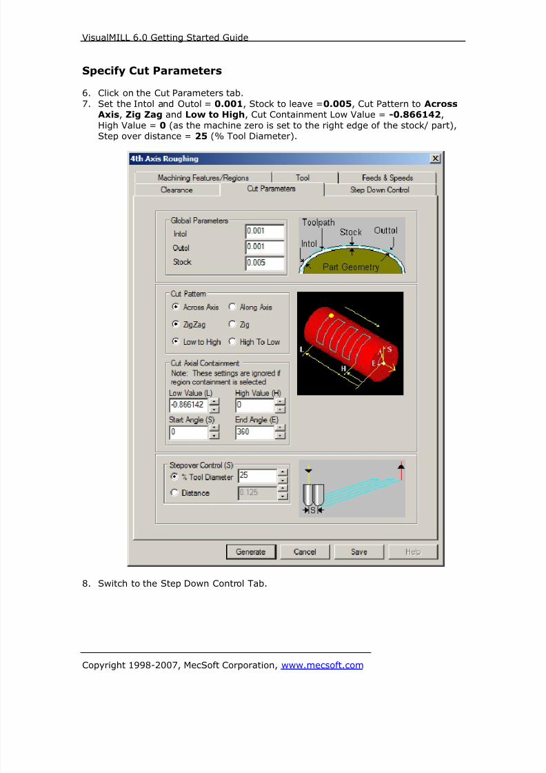
8/16/2019 Visual Mill Getting Started Guide
http://slidepdf.com/reader/full/visual-mill-getting-started-guide 310/411
VisualMILL 6.0 Getting Started Guide
Copyright 1998-2007, MecSoft Corporation, www.mecsoft.com
Specify Cut Parameters
6. Click on the Cut Parameters tab.
7. Set the Intol and Outol = 0.001, Stock to leave =0.005, Cut Pattern to AcrossAxis, Zig Zag and Low to High, Cut Containment Low Value = -0.866142,
High Value = 0 (as the machine zero is set to the right edge of the stock/ part),
Step over distance = 25 (% Tool Diameter).
8. Switch to the Step Down Control Tab.

8/16/2019 Visual Mill Getting Started Guide
http://slidepdf.com/reader/full/visual-mill-getting-started-guide 311/411
VisualMILL 6.0 Getting Started Guide
Copyright 1998-2007, MecSoft Corporation, www.mecsoft.com
Step Down Control9. Use the Following Settings.
a. Cut Levels, Check Top (T) and specify Top (T) = 0.56 (radius ofstock material)
b. Step Down Control (dR) = 75 (% Tool Diameter).
10. Click Generate. The 4th axis Roughing toolpath is now generated, and theOperation is listed under the VisualMILL-MOps browser.

8/16/2019 Visual Mill Getting Started Guide
http://slidepdf.com/reader/full/visual-mill-getting-started-guide 312/411
VisualMILL 6.0 Getting Started Guide
Copyright 1998-2007, MecSoft Corporation, www.mecsoft.com
11. Switch to Simulate tab, select 4 Axis Roughing, and click Simulate to run thesimulation.

8/16/2019 Visual Mill Getting Started Guide
http://slidepdf.com/reader/full/visual-mill-getting-started-guide 313/411
VisualMILL 6.0 Getting Started Guide
Copyright 1998-2007, MecSoft Corporation, www.mecsoft.com
4 axis Finishing
We will now use 4th Axis Finishing operation to finish the part using a 0.0625” Ball
End Mill.
In this method, the tool is always normal to the axis of table rotation (continuous
mode). The tool motions can be parallel to or normal to the rotation axis.From the Create Operations tab, select 4 axis Milling and 4 Axis Finishing.
This brings up the Finishing Operations dialog. We will go over the steps for
creating the pocketing operation.
1. Switch to the Tools tab inside the 4 Axis Finishing operation dialog and select
BallMill-0.0625.
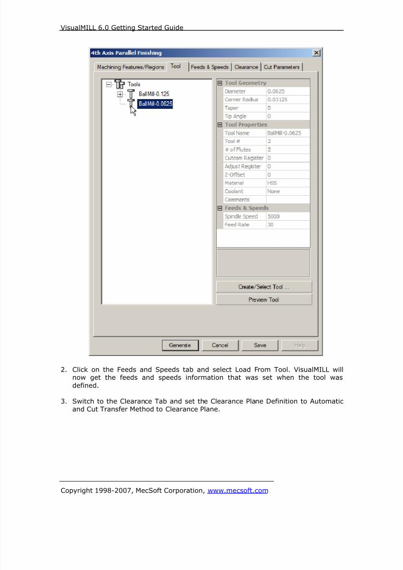
8/16/2019 Visual Mill Getting Started Guide
http://slidepdf.com/reader/full/visual-mill-getting-started-guide 314/411
VisualMILL 6.0 Getting Started Guide
Copyright 1998-2007, MecSoft Corporation, www.mecsoft.com
2. Click on the Feeds and Speeds tab and select Load From Tool. VisualMILL willnow get the feeds and speeds information that was set when the tool was
defined.
3. Switch to the Clearance Tab and set the Clearance Plane Definition to Automaticand Cut Transfer Method to Clearance Plane.
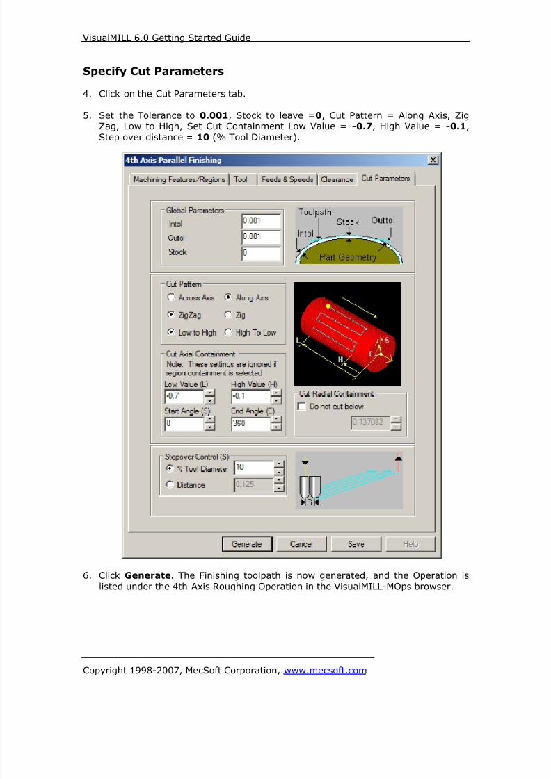
8/16/2019 Visual Mill Getting Started Guide
http://slidepdf.com/reader/full/visual-mill-getting-started-guide 315/411
VisualMILL 6.0 Getting Started Guide
Copyright 1998-2007, MecSoft Corporation, www.mecsoft.com
Specify Cut Parameters
4. Click on the Cut Parameters tab.
5. Set the Tolerance to 0.001, Stock to leave =0, Cut Pattern = Along Axis, ZigZag, Low to High, Set Cut Containment Low Value = -0.7, High Value = -0.1,
Step over distance = 10 (% Tool Diameter).
6. Click Generate. The Finishing toolpath is now generated, and the Operation is
listed under the 4th Axis Roughing Operation in the VisualMILL-MOps browser.

8/16/2019 Visual Mill Getting Started Guide
http://slidepdf.com/reader/full/visual-mill-getting-started-guide 316/411
VisualMILL 6.0 Getting Started Guide
Copyright 1998-2007, MecSoft Corporation, www.mecsoft.com
7. Switch to Simulate tab, select 4 Axis Finishing, and click Simulate to run the
simulation.

8/16/2019 Visual Mill Getting Started Guide
http://slidepdf.com/reader/full/visual-mill-getting-started-guide 317/411
VisualMILL 6.0 Getting Started Guide
Copyright 1998-2007, MecSoft Corporation, www.mecsoft.com
Post Processing
1. Select Machining Operations from the Create Operations tab and right click and
select post process.
2. Specify the File Name as Ring.nc and click save.
The post by default is set to Haas as specified under the Post processor setup. You
can change the post processor by selecting a different one from the drop down menu
in the list. The posted g code by default will be saved to the folder where the part fileis located.
End of Tutorial 10!

8/16/2019 Visual Mill Getting Started Guide
http://slidepdf.com/reader/full/visual-mill-getting-started-guide 318/411
VisualMILL 6.0 Getting Started Guide
Copyright 1998-2007, MecSoft Corporation, www.mecsoft.com
Tutorial 11: Engraving on a Cylinder
8/16/2019 Visual Mill Getting Started Guide
http://slidepdf.com/reader/full/visual-mill-getting-started-guide 319/411

8/16/2019 Visual Mill Getting Started Guide
http://slidepdf.com/reader/full/visual-mill-getting-started-guide 320/411
VisualMILL 6.0 Getting Started Guide
Copyright 1998-2007, MecSoft Corporation, www.mecsoft.com
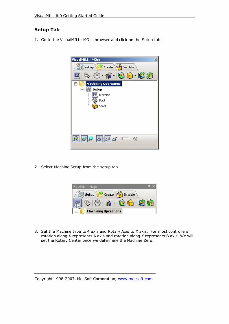
8/16/2019 Visual Mill Getting Started Guide
http://slidepdf.com/reader/full/visual-mill-getting-started-guide 321/411
VisualMILL 6.0 Getting Started Guide
Copyright 1998-2007, MecSoft Corporation, www.mecsoft.com
Setup Tab
1. Go to the VisualMILL- MOps browser and click on the Setup tab.
2. Select Machine Setup from the setup tab.
3. Set the Machine type to 4 axis and Rotary Axis to X axis. For most controllers
rotation along X represents A axis and rotation along Y represents B axis. We willset the Rotary Center once we determine the Machine Zero.
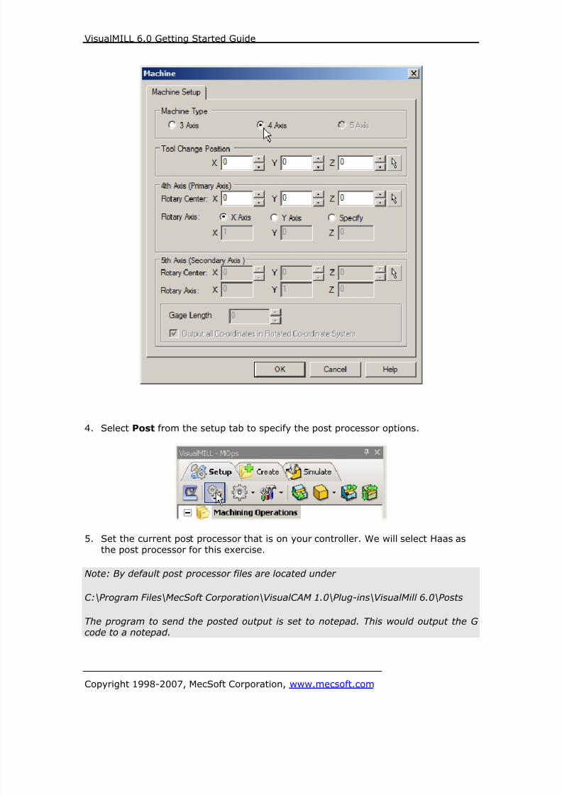
8/16/2019 Visual Mill Getting Started Guide
http://slidepdf.com/reader/full/visual-mill-getting-started-guide 322/411
VisualMILL 6.0 Getting Started Guide
Copyright 1998-2007, MecSoft Corporation, www.mecsoft.com
4. Select Post from the setup tab to specify the post processor options.
5. Set the current post processor that is on your controller. We will select Haas asthe post processor for this exercise.
Note: By default post processor files are located under
C:\Program Files\MecSoft Corporation\VisualCAM 1.0\Plug-ins\VisualMill 6.0\Posts
The program to send the posted output is set to notepad. This would output the Gcode to a notepad.

8/16/2019 Visual Mill Getting Started Guide
http://slidepdf.com/reader/full/visual-mill-getting-started-guide 323/411
VisualMILL 6.0 Getting Started Guide
Copyright 1998-2007, MecSoft Corporation, www.mecsoft.com
Create Stock Geometry
1. Select Create/Load stock from the setup tab and create a Cylinder Stock.
2. This brings up the Cylinder Stock parameters. Set the Axis (rotary) = X, Radius
= 1” and Length (L) = 8”. Leave the other parameters as default and click OK.
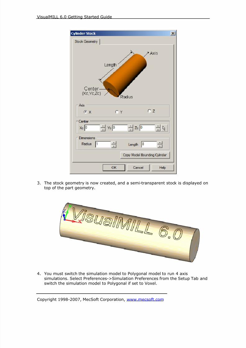
8/16/2019 Visual Mill Getting Started Guide
http://slidepdf.com/reader/full/visual-mill-getting-started-guide 324/411
VisualMILL 6.0 Getting Started Guide
Copyright 1998-2007, MecSoft Corporation, www.mecsoft.com
3. The stock geometry is now created, and a semi-transparent stock is displayed ontop of the part geometry.
4. You must switch the simulation model to Polygonal model to run 4 axis
simulations. Select Preferences->Simulation Preferences from the Setup Tab andswitch the simulation model to Polygonal if set to Voxel.
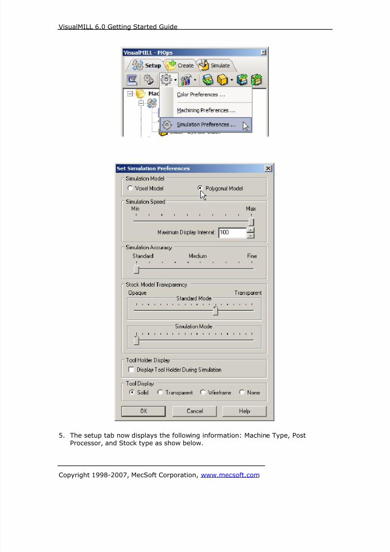
8/16/2019 Visual Mill Getting Started Guide
http://slidepdf.com/reader/full/visual-mill-getting-started-guide 325/411
VisualMILL 6.0 Getting Started Guide
Copyright 1998-2007, MecSoft Corporation, www.mecsoft.com
5. The setup tab now displays the following information: Machine Type, PostProcessor, and Stock type as show below.

8/16/2019 Visual Mill Getting Started Guide
http://slidepdf.com/reader/full/visual-mill-getting-started-guide 326/411
VisualMILL 6.0 Getting Started Guide
Copyright 1998-2007, MecSoft Corporation, www.mecsoft.com
Locate Machine Zero
1. The steps below help you determine the machine home (also know as machine
zero or tool touch off point) for the part/stock geometry.2. Select Locate WCS from the Setup tab.
3. Under Set WCS Origin, choose Set to Stock Box, the Zero Face to Mid Z, and
Zero Position to West. This sets the machine home to the center of the stockmaterial and the left most edge of the part geometry.
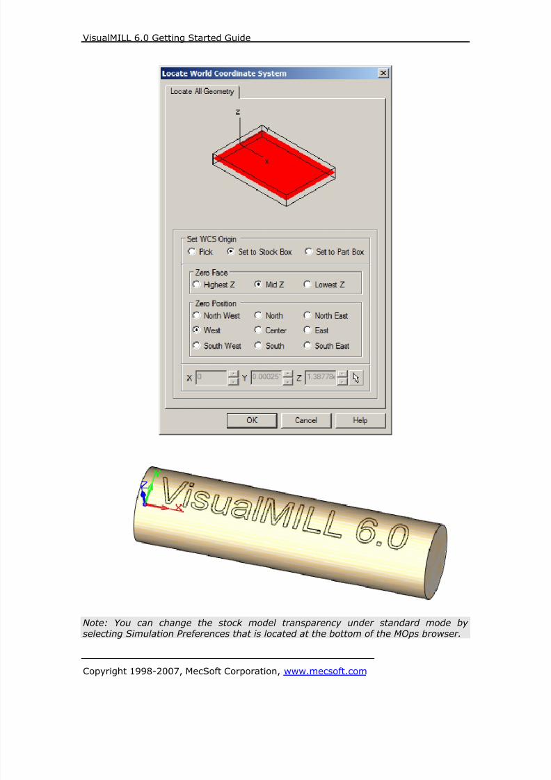
8/16/2019 Visual Mill Getting Started Guide
http://slidepdf.com/reader/full/visual-mill-getting-started-guide 327/411
VisualMILL 6.0 Getting Started Guide
Copyright 1998-2007, MecSoft Corporation, www.mecsoft.com
Note: You can change the stock model transparency under standard mode byselecting Simulation Preferences that is located at the bottom of the MOps browser.
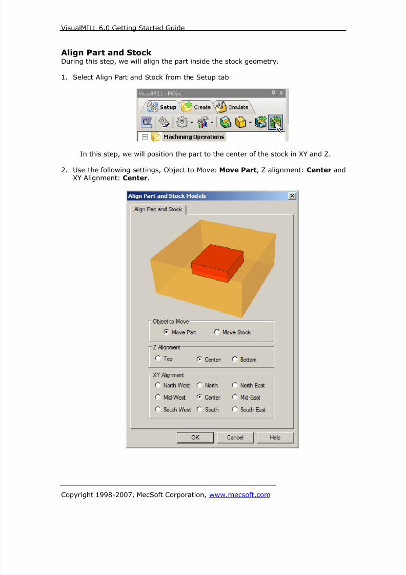
8/16/2019 Visual Mill Getting Started Guide
http://slidepdf.com/reader/full/visual-mill-getting-started-guide 328/411
VisualMILL 6.0 Getting Started Guide
Copyright 1998-2007, MecSoft Corporation, www.mecsoft.com
Align Part and StockDuring this step, we will align the part inside the stock geometry.
1. Select Align Part and Stock from the Setup tab
In this step, we will position the part to the center of the stock in XY and Z.
2. Use the following settings, Object to Move: Move Part, Z alignment: Center andXY Alignment: Center.
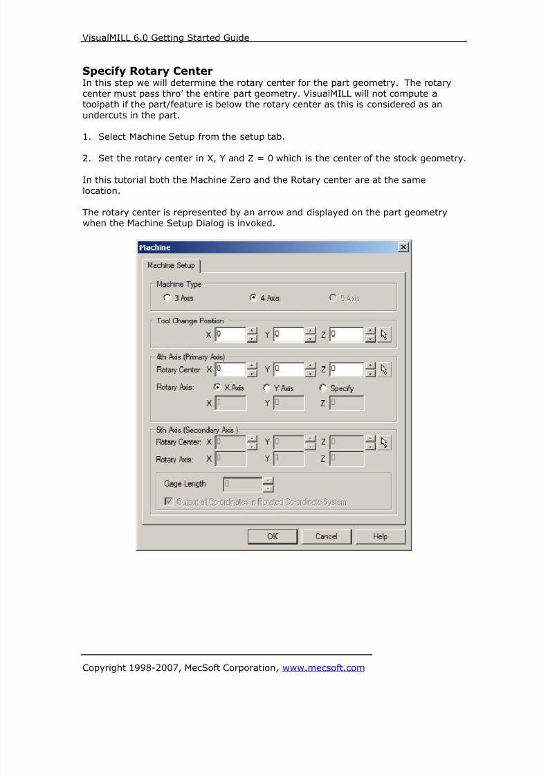
8/16/2019 Visual Mill Getting Started Guide
http://slidepdf.com/reader/full/visual-mill-getting-started-guide 329/411
VisualMILL 6.0 Getting Started Guide
Copyright 1998-2007, MecSoft Corporation, www.mecsoft.com
Specify Rotary CenterIn this step we will determine the rotary center for the part geometry. The rotary
center must pass thro’ the entire part geometry. VisualMILL will not compute atoolpath if the part/feature is below the rotary center as this is considered as an
undercuts in the part.
1. Select Machine Setup from the setup tab.
2. Set the rotary center in X, Y and Z = 0 which is the center of the stock geometry.
In this tutorial both the Machine Zero and the Rotary center are at the same
location.
The rotary center is represented by an arrow and displayed on the part geometrywhen the Machine Setup Dialog is invoked.
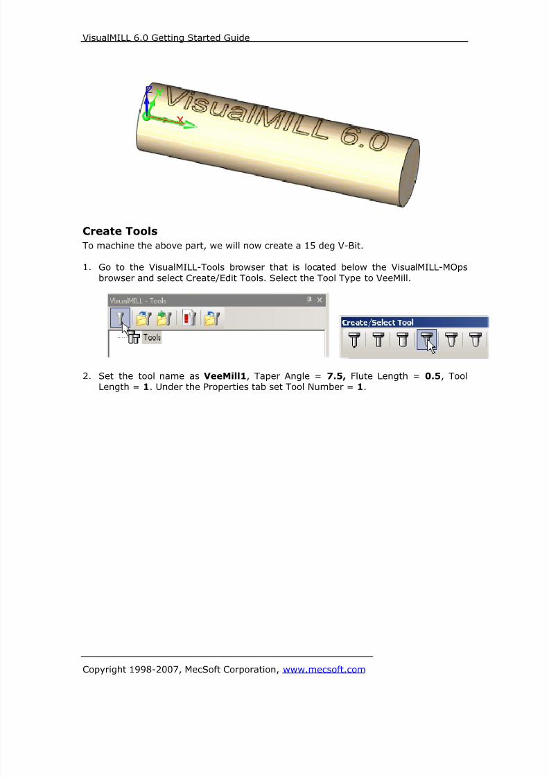
8/16/2019 Visual Mill Getting Started Guide
http://slidepdf.com/reader/full/visual-mill-getting-started-guide 330/411
VisualMILL 6.0 Getting Started Guide
Copyright 1998-2007, MecSoft Corporation, www.mecsoft.com
Create Tools
To machine the above part, we will now create a 15 deg V-Bit.
1. Go to the VisualMILL-Tools browser that is located below the VisualMILL-MOps
browser and select Create/Edit Tools. Select the Tool Type to VeeMill.
2. Set the tool name as VeeMill1, Taper Angle = 7.5, Flute Length = 0.5, ToolLength = 1. Under the Properties tab set Tool Number = 1.

8/16/2019 Visual Mill Getting Started Guide
http://slidepdf.com/reader/full/visual-mill-getting-started-guide 331/411
VisualMILL 6.0 Getting Started Guide
Copyright 1998-2007, MecSoft Corporation, www.mecsoft.com
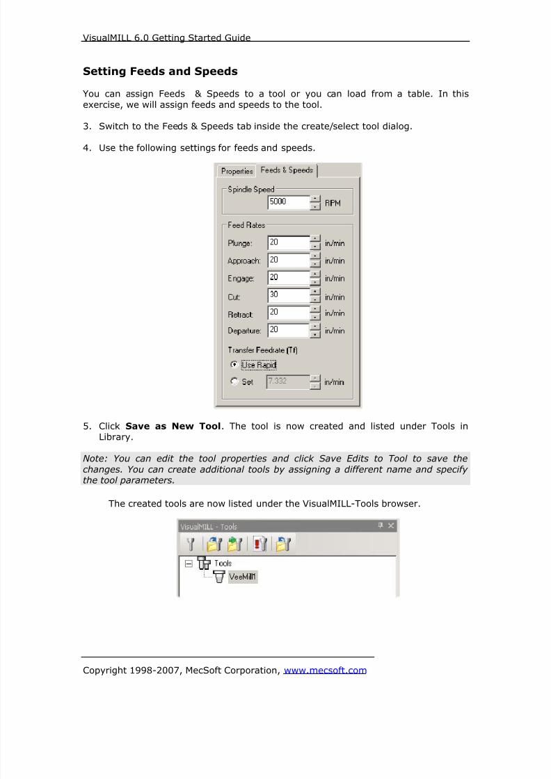
8/16/2019 Visual Mill Getting Started Guide
http://slidepdf.com/reader/full/visual-mill-getting-started-guide 332/411
VisualMILL 6.0 Getting Started Guide
Copyright 1998-2007, MecSoft Corporation, www.mecsoft.com
Setting Feeds and Speeds
You can assign Feeds & Speeds to a tool or you can load from a table. In this
exercise, we will assign feeds and speeds to the tool.
3. Switch to the Feeds & Speeds tab inside the create/select tool dialog.
4. Use the following settings for feeds and speeds.
5. Click Save as New Tool. The tool is now created and listed under Tools inLibrary.
Note: You can edit the tool properties and click Save Edits to Tool to save the
changes. You can create additional tools by assigning a different name and specifythe tool parameters.
The created tools are now listed under the VisualMILL-Tools browser.

8/16/2019 Visual Mill Getting Started Guide
http://slidepdf.com/reader/full/visual-mill-getting-started-guide 333/411
VisualMILL 6.0 Getting Started Guide
Copyright 1998-2007, MecSoft Corporation, www.mecsoft.com
Create Machining Operations
We will engrave the text on the cylinder using 4 Axis Engraving.
This method machines text or logos by following the contours of the selected regionsby projecting the text onto the cylinder.
Switch to the Create Operations tab in VisualMILL-Mops browser.
4 Axis Engraving
1. Select 4 Axis Milling and choose Engraving.

8/16/2019 Visual Mill Getting Started Guide
http://slidepdf.com/reader/full/visual-mill-getting-started-guide 334/411
VisualMILL 6.0 Getting Started Guide
Copyright 1998-2007, MecSoft Corporation, www.mecsoft.com
If the rotary center is not set to the same location as the Machine Zero, a
warning message dialog would be displayed at all times when a 4 axis
machining operation is selected. Users can override this message by clickingOK in the dialog.
Note: You can check Do no show this dialog again to stop the warning message
appearing again when you create/edit a 4 axis machining operation.
2. This brings up the 4 Axis Engraving Operation Dialog. We will now go over thesteps for creating the toolpath.
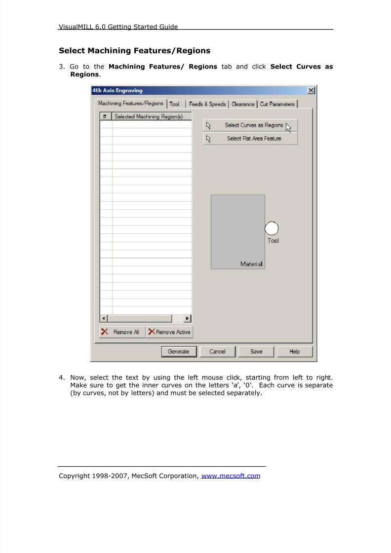
8/16/2019 Visual Mill Getting Started Guide
http://slidepdf.com/reader/full/visual-mill-getting-started-guide 335/411
VisualMILL 6.0 Getting Started Guide
Copyright 1998-2007, MecSoft Corporation, www.mecsoft.com
Select Machining Features/Regions
3. Go to the Machining Features/ Regions tab and click Select Curves as
Regions.
4. Now, select the text by using the left mouse click, starting from left to right.
Make sure to get the inner curves on the letters ‘a’, ‘0’. Each curve is separate(by curves, not by letters) and must be selected separately.

8/16/2019 Visual Mill Getting Started Guide
http://slidepdf.com/reader/full/visual-mill-getting-started-guide 336/411
VisualMILL 6.0 Getting Started Guide
Copyright 1998-2007, MecSoft Corporation, www.mecsoft.com
5. Right mouse click or select enter from the keypad to complete the selection.
6. The selected regions are now displayed under Machining Regions.
7. Switch to the Tools tab inside the 4th Axis Engraving operation and select
VeeMill1.

8/16/2019 Visual Mill Getting Started Guide
http://slidepdf.com/reader/full/visual-mill-getting-started-guide 337/411
VisualMILL 6.0 Getting Started Guide
Copyright 1998-2007, MecSoft Corporation, www.mecsoft.com

8/16/2019 Visual Mill Getting Started Guide
http://slidepdf.com/reader/full/visual-mill-getting-started-guide 338/411
VisualMILL 6.0 Getting Started Guide
Copyright 1998-2007, MecSoft Corporation, www.mecsoft.com
8. Click on the Feeds and Speeds tab and select Load From Tool. VisualMILL will
now get the feeds and speeds information that was set when the tool wasdefined.
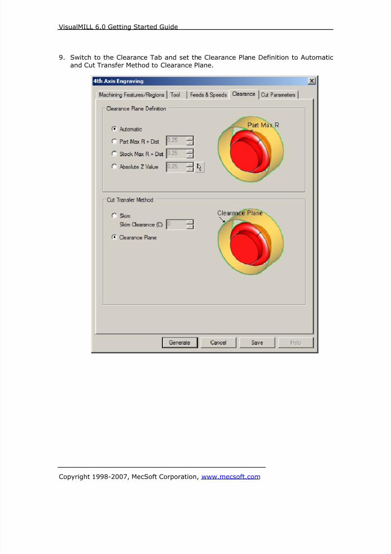
8/16/2019 Visual Mill Getting Started Guide
http://slidepdf.com/reader/full/visual-mill-getting-started-guide 339/411
VisualMILL 6.0 Getting Started Guide
Copyright 1998-2007, MecSoft Corporation, www.mecsoft.com
9. Switch to the Clearance Tab and set the Clearance Plane Definition to Automatic
and Cut Transfer Method to Clearance Plane.
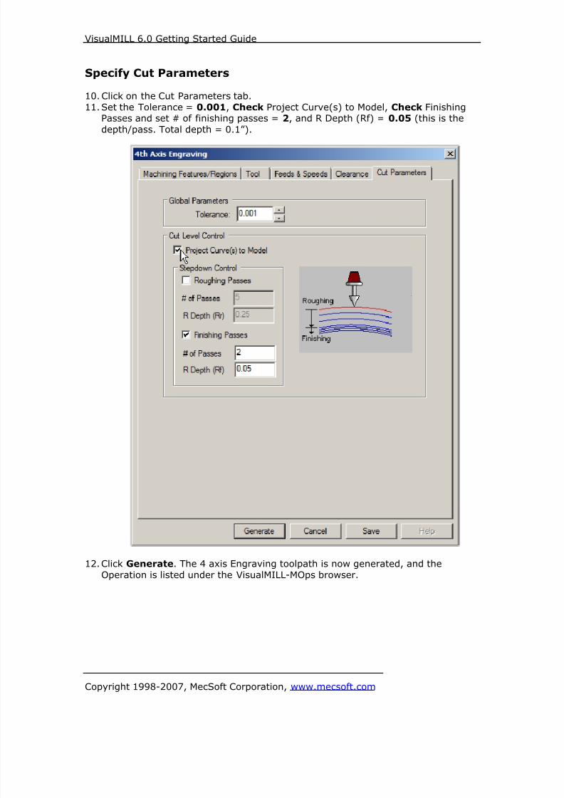
8/16/2019 Visual Mill Getting Started Guide
http://slidepdf.com/reader/full/visual-mill-getting-started-guide 340/411
VisualMILL 6.0 Getting Started Guide
Copyright 1998-2007, MecSoft Corporation, www.mecsoft.com
Specify Cut Parameters
10. Click on the Cut Parameters tab.
11. Set the Tolerance = 0.001, Check Project Curve(s) to Model, Check FinishingPasses and set # of finishing passes = 2, and R Depth (Rf) = 0.05 (this is the
depth/pass. Total depth = 0.1”).
12. Click Generate. The 4 axis Engraving toolpath is now generated, and the
Operation is listed under the VisualMILL-MOps browser.
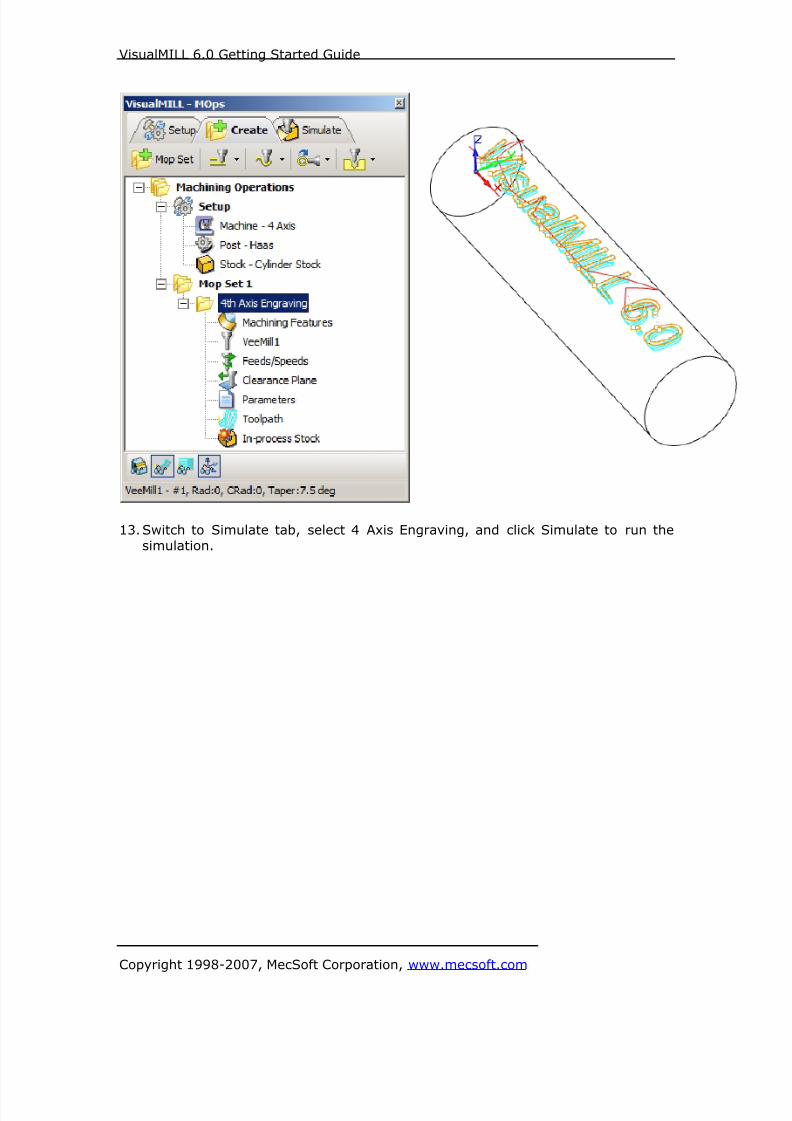
8/16/2019 Visual Mill Getting Started Guide
http://slidepdf.com/reader/full/visual-mill-getting-started-guide 341/411
VisualMILL 6.0 Getting Started Guide
Copyright 1998-2007, MecSoft Corporation, www.mecsoft.com
13. Switch to Simulate tab, select 4 Axis Engraving, and click Simulate to run the
simulation.

8/16/2019 Visual Mill Getting Started Guide
http://slidepdf.com/reader/full/visual-mill-getting-started-guide 342/411
VisualMILL 6.0 Getting Started Guide
Copyright 1998-2007, MecSoft Corporation, www.mecsoft.com
Post Processing
1. Select Machining Operations from the Create Operations tab and right click and
select post process.
2. Specify the File Name as 4AxisEngrave.nc and click save.

8/16/2019 Visual Mill Getting Started Guide
http://slidepdf.com/reader/full/visual-mill-getting-started-guide 343/411
VisualMILL 6.0 Getting Started Guide
Copyright 1998-2007, MecSoft Corporation, www.mecsoft.com
The post by default is set to Haas as specified under the Post processor setup. You
can change the post processor by selecting a different one from the drop down menu
in the list. The posted g code by default will be saved to the folder where the part fileis located.
End of Tutorial 11!

8/16/2019 Visual Mill Getting Started Guide
http://slidepdf.com/reader/full/visual-mill-getting-started-guide 344/411
VisualMILL 6.0 Getting Started Guide
Copyright 1998-2007, MecSoft Corporation, www.mecsoft.com
Tutorial 12: Machining a Ring
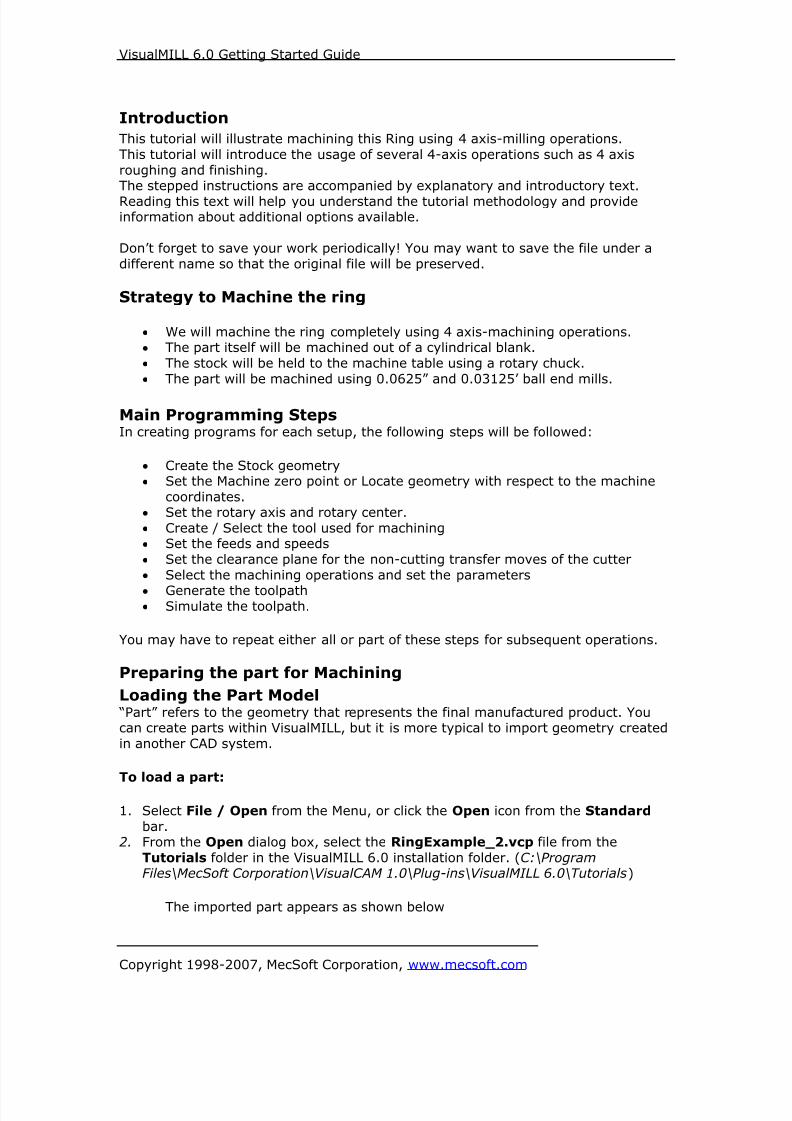
8/16/2019 Visual Mill Getting Started Guide
http://slidepdf.com/reader/full/visual-mill-getting-started-guide 345/411
VisualMILL 6.0 Getting Started Guide
Copyright 1998-2007, MecSoft Corporation, www.mecsoft.com
Introduction
This tutorial will illustrate machining this Ring using 4 axis-milling operations.
This tutorial will introduce the usage of several 4-axis operations such as 4 axis
roughing and finishing.The stepped instructions are accompanied by explanatory and introductory text.
Reading this text will help you understand the tutorial methodology and provideinformation about additional options available.
Don’t forget to save your work periodically! You may want to save the file under a
different name so that the original file will be preserved.
Strategy to Machine the ring
• We will machine the ring completely using 4 axis-machining operations.
• The part itself will be machined out of a cylindrical blank.
• The stock will be held to the machine table using a rotary chuck.
• The part will be machined using 0.0625” and 0.03125’ ball end mills.
Main Programming StepsIn creating programs for each setup, the following steps will be followed:
• Create the Stock geometry
• Set the Machine zero point or Locate geometry with respect to the machine
coordinates.
• Set the rotary axis and rotary center.
• Create / Select the tool used for machining
• Set the feeds and speeds
• Set the clearance plane for the non-cutting transfer moves of the cutter
• Select the machining operations and set the parameters
• Generate the toolpath• Simulate the toolpath.
You may have to repeat either all or part of these steps for subsequent operations.
Preparing the part for Machining
Loading the Part Model “Part” refers to the geometry that represents the final manufactured product. Youcan create parts within VisualMILL, but it is more typical to import geometry created
in another CAD system.
To load a part:
1. Select File / Open from the Menu, or click the Open icon from the Standard
bar.2. From the Open dialog box, select the RingExample_2.vcp file from the
Tutorials folder in the VisualMILL 6.0 installation folder. (C:\ProgramFiles\MecSoft Corporation\VisualCAM 1.0\Plug-ins\VisualMILL 6.0\Tutorials)
The imported part appears as shown below

8/16/2019 Visual Mill Getting Started Guide
http://slidepdf.com/reader/full/visual-mill-getting-started-guide 346/411
VisualMILL 6.0 Getting Started Guide
Copyright 1998-2007, MecSoft Corporation, www.mecsoft.com

8/16/2019 Visual Mill Getting Started Guide
http://slidepdf.com/reader/full/visual-mill-getting-started-guide 347/411
VisualMILL 6.0 Getting Started Guide
Copyright 1998-2007, MecSoft Corporation, www.mecsoft.com
Setup Tab
1. Go to the VisualMILL- MOps browser and click on the Setup tab.
2. Select Machine Setup from the setup tab.
3. Set the Machine type to 4 axis and Rotary Axis to X axis. For most controllers
rotation along X represents A axis and rotation along Y represents B axis. We willset the Rotary Center once we determine the Machine Zero.

8/16/2019 Visual Mill Getting Started Guide
http://slidepdf.com/reader/full/visual-mill-getting-started-guide 348/411
VisualMILL 6.0 Getting Started Guide
Copyright 1998-2007, MecSoft Corporation, www.mecsoft.com
4. Select Post from the setup tab to specify the post processor options.
5. Set the current post processor that is on your controller. We will select Haas asthe post processor for this exercise.
Note: By default post processor files are located under
C:\Program Files\MecSoft Corporation\VisualCAM 1.0\Plug-ins\VisualMill 6.0\Posts
The program to send the posted output is set to notepad. This would output the Gcode to a notepad.

8/16/2019 Visual Mill Getting Started Guide
http://slidepdf.com/reader/full/visual-mill-getting-started-guide 349/411
VisualMILL 6.0 Getting Started Guide
Copyright 1998-2007, MecSoft Corporation, www.mecsoft.com
Create Stock Geometry
1. Select Create/Load stock from the setup tab and create a Cylinder Stock.
2. This brings up the Cylinder Stock parameters. Set the Axis (rotary) = X, Radius
= 0.48” and Length (L) = 0.4. Leave the other parameters as default and click
OK.
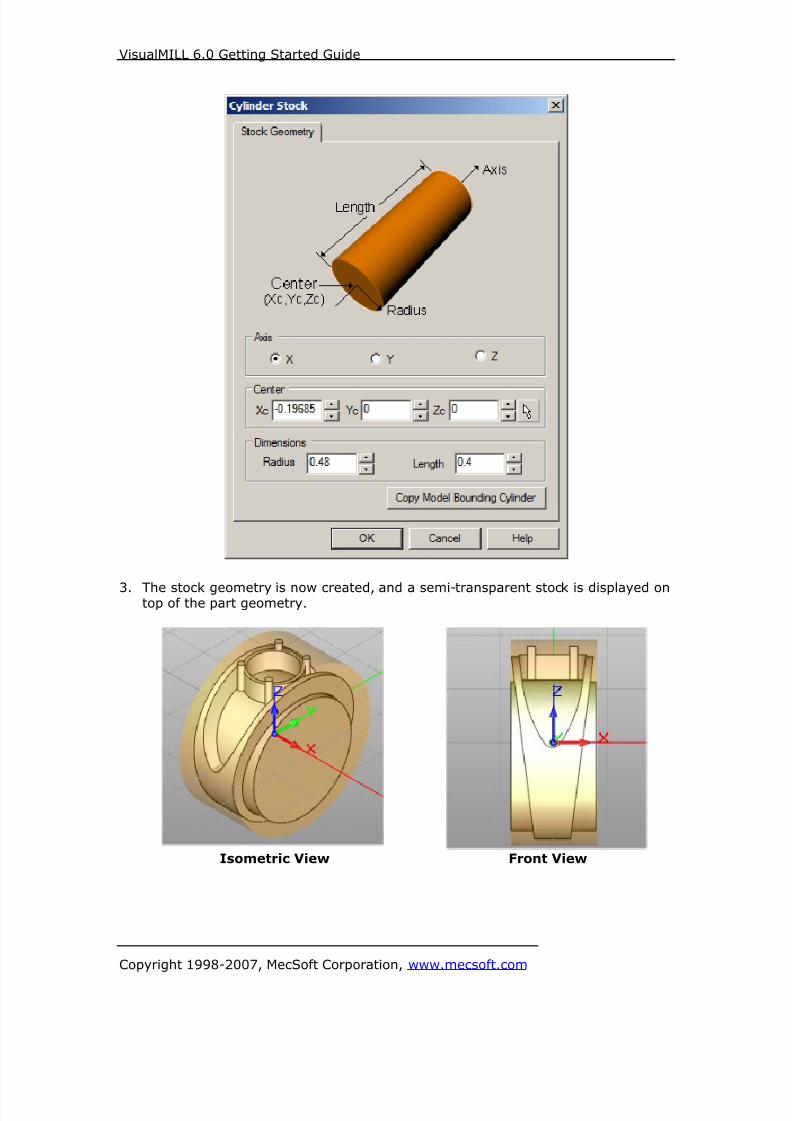
8/16/2019 Visual Mill Getting Started Guide
http://slidepdf.com/reader/full/visual-mill-getting-started-guide 350/411
VisualMILL 6.0 Getting Started Guide
Copyright 1998-2007, MecSoft Corporation, www.mecsoft.com
3. The stock geometry is now created, and a semi-transparent stock is displayed ontop of the part geometry.
Isometric View Front View
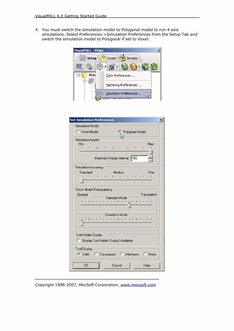
8/16/2019 Visual Mill Getting Started Guide
http://slidepdf.com/reader/full/visual-mill-getting-started-guide 351/411
VisualMILL 6.0 Getting Started Guide
Copyright 1998-2007, MecSoft Corporation, www.mecsoft.com
4. You must switch the simulation model to Polygonal model to run 4 axis
simulations. Select Preferences->Simulation Preferences from the Setup Tab and
switch the simulation model to Polygonal if set to Voxel.

8/16/2019 Visual Mill Getting Started Guide
http://slidepdf.com/reader/full/visual-mill-getting-started-guide 352/411
VisualMILL 6.0 Getting Started Guide
Copyright 1998-2007, MecSoft Corporation, www.mecsoft.com
5. The setup tab now displays the following information: Machine Type, Post
Processor, and Stock type as show below.
Locate Machine Zero
1. The steps below help you determine the machine home (also know as machine
zero or tool touch off point) for the part/stock geometry.
2. Select Locate WCS from the Setup tab.
3. Under Set WCS Origin, choose Set to Stock Box, the Zero Face to Highest Z,
and Zero Position to East. This sets the machine home to the top of the stockmaterial and the right most edge of the part geometry.

8/16/2019 Visual Mill Getting Started Guide
http://slidepdf.com/reader/full/visual-mill-getting-started-guide 353/411
VisualMILL 6.0 Getting Started Guide
Copyright 1998-2007, MecSoft Corporation, www.mecsoft.com
Isometric View Front View

8/16/2019 Visual Mill Getting Started Guide
http://slidepdf.com/reader/full/visual-mill-getting-started-guide 354/411
VisualMILL 6.0 Getting Started Guide
Copyright 1998-2007, MecSoft Corporation, www.mecsoft.com
Note: You can change the stock model transparency under standard mode by
selecting Simulation Preferences that is located at the bottom of the MOps browser.
Align Part and StockDuring this step, we will align the part inside the stock geometry.
1. Select Align Part and Stock from the Setup tab
In this step, we will position the part to the center of the stock in XY & Z.
2. Use the following settings, Object to Move: Move Part, Z alignment: Center and
XY Alignment: Mid-East.
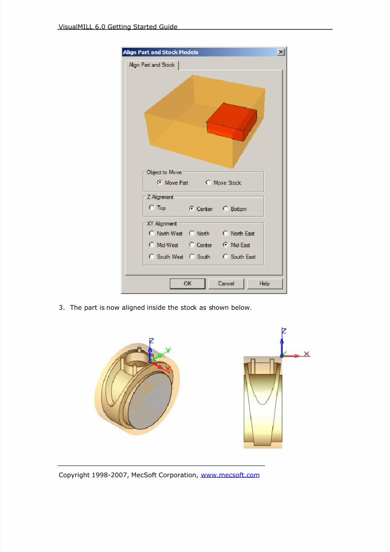
8/16/2019 Visual Mill Getting Started Guide
http://slidepdf.com/reader/full/visual-mill-getting-started-guide 355/411
VisualMILL 6.0 Getting Started Guide
Copyright 1998-2007, MecSoft Corporation, www.mecsoft.com
3. The part is now aligned inside the stock as shown below.
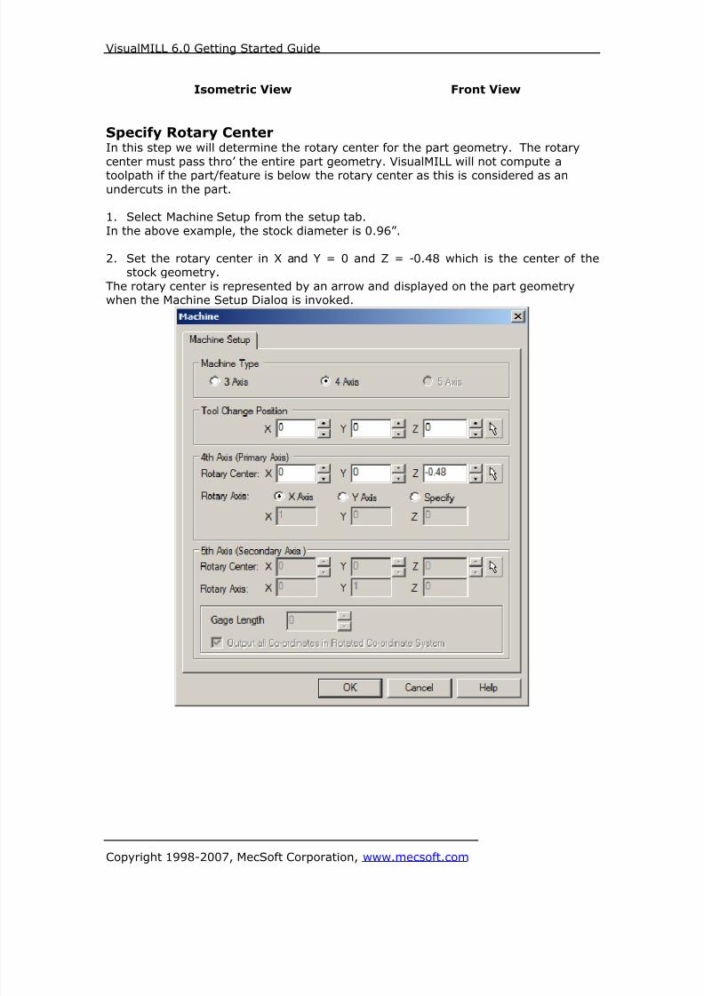
8/16/2019 Visual Mill Getting Started Guide
http://slidepdf.com/reader/full/visual-mill-getting-started-guide 356/411
VisualMILL 6.0 Getting Started Guide
Copyright 1998-2007, MecSoft Corporation, www.mecsoft.com
Isometric View Front View
Specify Rotary CenterIn this step we will determine the rotary center for the part geometry. The rotary
center must pass thro’ the entire part geometry. VisualMILL will not compute a
toolpath if the part/feature is below the rotary center as this is considered as anundercuts in the part.
1. Select Machine Setup from the setup tab.
In the above example, the stock diameter is 0.96”.
2. Set the rotary center in X and Y = 0 and Z = -0.48 which is the center of thestock geometry.
The rotary center is represented by an arrow and displayed on the part geometrywhen the Machine Setup Dialog is invoked.

8/16/2019 Visual Mill Getting Started Guide
http://slidepdf.com/reader/full/visual-mill-getting-started-guide 357/411
VisualMILL 6.0 Getting Started Guide
Copyright 1998-2007, MecSoft Corporation, www.mecsoft.com
Create Tools
To machine the above part, we will now create 0.0625” and 0.03125” Ball End Mills.
1. Go to the VisualMILL-Tools browser that is located below the VisualMILL-MOpsbrowser and select Create/Edit Tools. Select the Tool Type to Ball End Mill.
2. Set the tool name as BallMill-0.0625, Tool Diameter = 0.0625 Flute Length =
1” and Tool Length = 1.5”. Under the Properties tab, set Tool Number = 1.
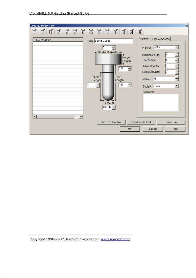
8/16/2019 Visual Mill Getting Started Guide
http://slidepdf.com/reader/full/visual-mill-getting-started-guide 358/411
VisualMILL 6.0 Getting Started Guide
Copyright 1998-2007, MecSoft Corporation, www.mecsoft.com

8/16/2019 Visual Mill Getting Started Guide
http://slidepdf.com/reader/full/visual-mill-getting-started-guide 359/411
VisualMILL 6.0 Getting Started Guide
Copyright 1998-2007, MecSoft Corporation, www.mecsoft.com
Setting Feeds and Speeds
You can assign Feeds & Speeds to a tool or you can load from a table. In this
exercise, we will assign feeds and speeds to the tool.
3. Switch to the Feeds & Speeds tab inside the create/select tool dialog.
4. Use the following settings for feeds and speeds.
5. Click Save as New Tool. The tool is now created and listed under Tools inLibrary.
Note: You can edit the tool properties and click Save Edits to Tool to save the
changes. You can create additional tools by assigning a different name and specifythe tool parameters.
6. Create a 2nd Ball End Mill with the following parameters.
a. Tool Name: BallMill-0.03125, Tool Number = 2.
b. Switch to Feeds & Speeds tab set Spindle Speed = 5000 rpm, plunge,approach & engage feed = 20 ipm, cut feed = 30 ipm, retract anddeparture feeds = 20 ipm. Set the Transfer Feedrate to Use Rapid.
c. Click Save as New Tool.
The created tools are now listed under the VisualMILL-Tools browser.
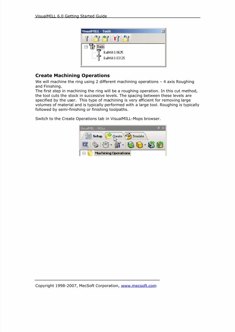
8/16/2019 Visual Mill Getting Started Guide
http://slidepdf.com/reader/full/visual-mill-getting-started-guide 360/411
VisualMILL 6.0 Getting Started Guide
Copyright 1998-2007, MecSoft Corporation, www.mecsoft.com
Create Machining Operations
We will machine the ring using 2 different machining operations – 4 axis Roughing
and Finishing.The first step in machining the ring will be a roughing operation. In this cut method,
the tool cuts the stock in successive levels. The spacing between these levels arespecified by the user. This type of machining is very efficient for removing large
volumes of material and is typically performed with a large tool. Roughing is typically
followed by semi-finishing or finishing toolpaths.
Switch to the Create Operations tab in VisualMILL-Mops browser.
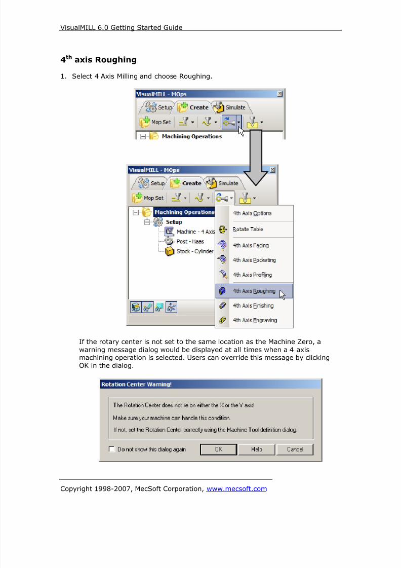
8/16/2019 Visual Mill Getting Started Guide
http://slidepdf.com/reader/full/visual-mill-getting-started-guide 361/411
VisualMILL 6.0 Getting Started Guide
Copyright 1998-2007, MecSoft Corporation, www.mecsoft.com
4th axis Roughing
1. Select 4 Axis Milling and choose Roughing.
If the rotary center is not set to the same location as the Machine Zero, a
warning message dialog would be displayed at all times when a 4 axismachining operation is selected. Users can override this message by clicking
OK in the dialog.
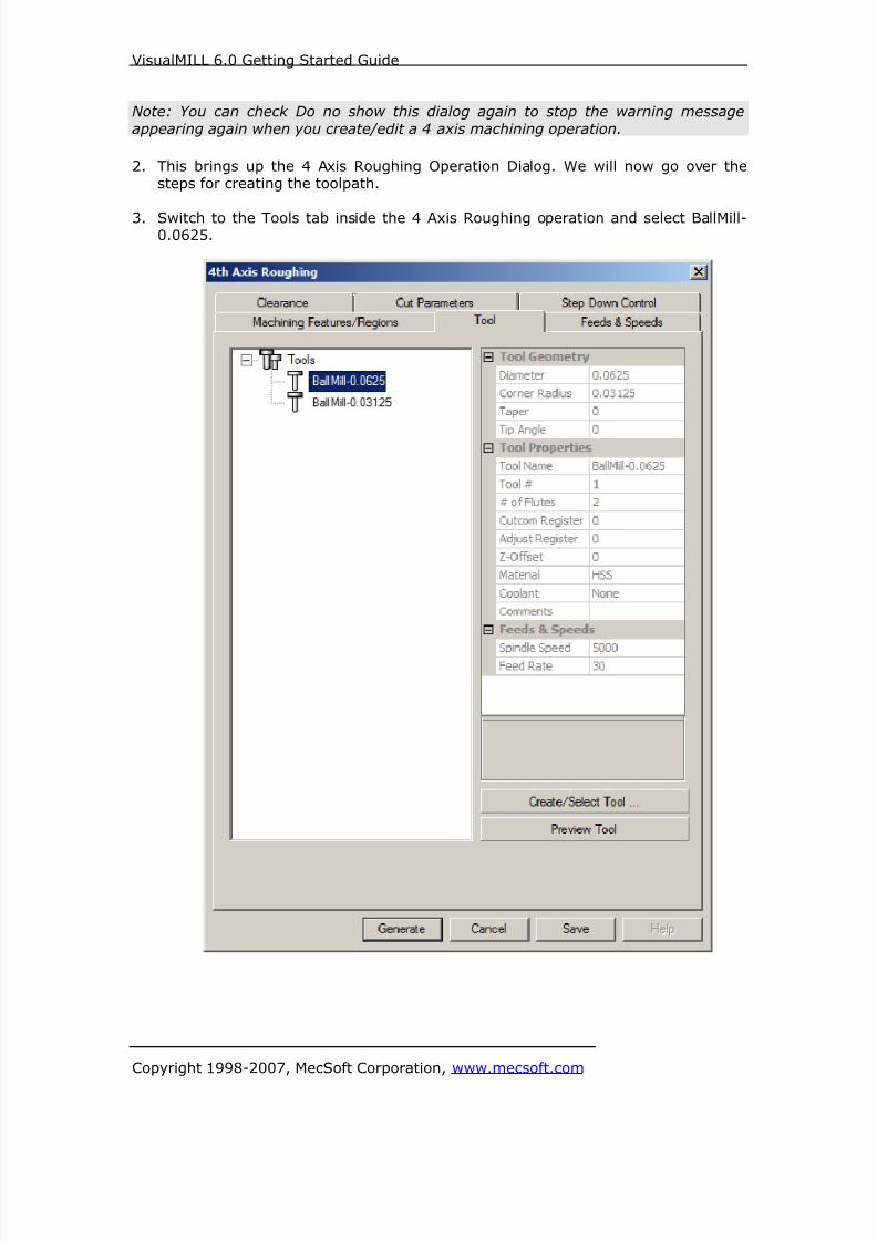
8/16/2019 Visual Mill Getting Started Guide
http://slidepdf.com/reader/full/visual-mill-getting-started-guide 362/411
VisualMILL 6.0 Getting Started Guide
Copyright 1998-2007, MecSoft Corporation, www.mecsoft.com
Note: You can check Do no show this dialog again to stop the warning message
appearing again when you create/edit a 4 axis machining operation.
2. This brings up the 4 Axis Roughing Operation Dialog. We will now go over thesteps for creating the toolpath.
3. Switch to the Tools tab inside the 4 Axis Roughing operation and select BallMill-0.0625.

8/16/2019 Visual Mill Getting Started Guide
http://slidepdf.com/reader/full/visual-mill-getting-started-guide 363/411
VisualMILL 6.0 Getting Started Guide
Copyright 1998-2007, MecSoft Corporation, www.mecsoft.com
4. Click on the Feeds and Speeds tab and select Load From Tool. VisualMILL will
now get the feeds and speeds information that was set when the tool wasdefined.

8/16/2019 Visual Mill Getting Started Guide
http://slidepdf.com/reader/full/visual-mill-getting-started-guide 364/411
VisualMILL 6.0 Getting Started Guide
Copyright 1998-2007, MecSoft Corporation, www.mecsoft.com
5. Switch to the Clearance Tab and set the Clearance Plane Definition to Automatic
and Cut Transfer Method to Clearance Plane.
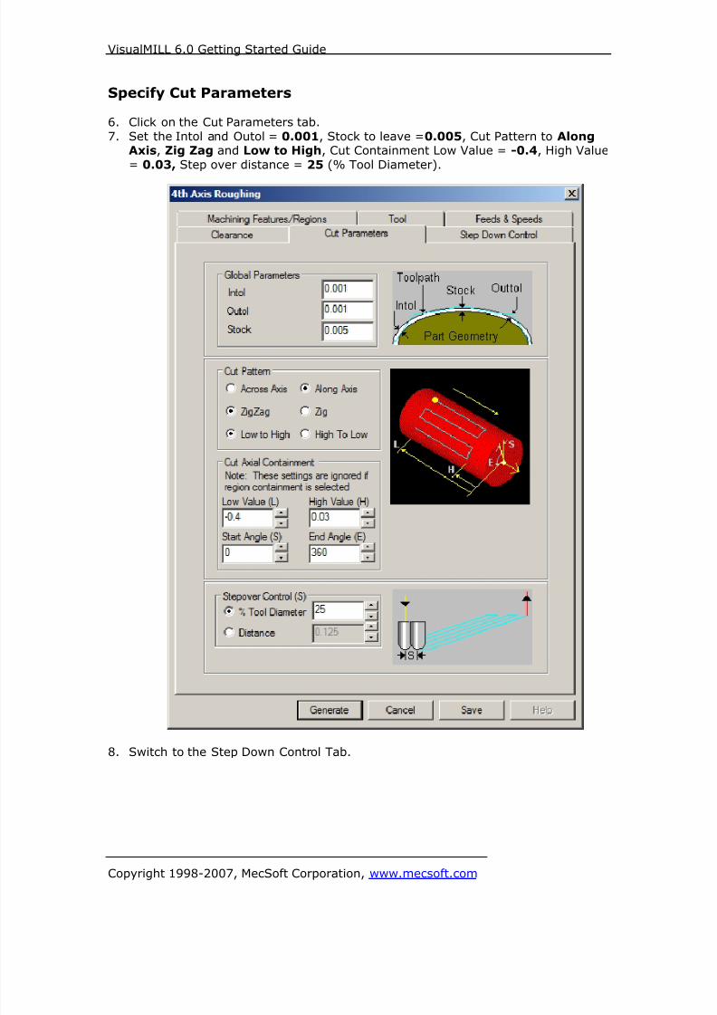
8/16/2019 Visual Mill Getting Started Guide
http://slidepdf.com/reader/full/visual-mill-getting-started-guide 365/411
VisualMILL 6.0 Getting Started Guide
Copyright 1998-2007, MecSoft Corporation, www.mecsoft.com
Specify Cut Parameters
6. Click on the Cut Parameters tab.
7. Set the Intol and Outol = 0.001, Stock to leave =0.005, Cut Pattern to AlongAxis, Zig Zag and Low to High, Cut Containment Low Value = -0.4, High Value
= 0.03, Step over distance = 25 (% Tool Diameter).
8. Switch to the Step Down Control Tab.

8/16/2019 Visual Mill Getting Started Guide
http://slidepdf.com/reader/full/visual-mill-getting-started-guide 366/411
VisualMILL 6.0 Getting Started Guide
Copyright 1998-2007, MecSoft Corporation, www.mecsoft.com
Step Down Control9. Use the Following Settings.
c. Cut Levels, Check Top (T) and specify Top (T) = 0.48 (radius ofstock material), Bottom (B) = 0.4, Step Down Control (dR) = 75 (%
Tool Diameter).
10. Click Generate. The 4 axis Roughing toolpath is now generated, and the
Operation is listed under the VisualMILL-MOps browser.
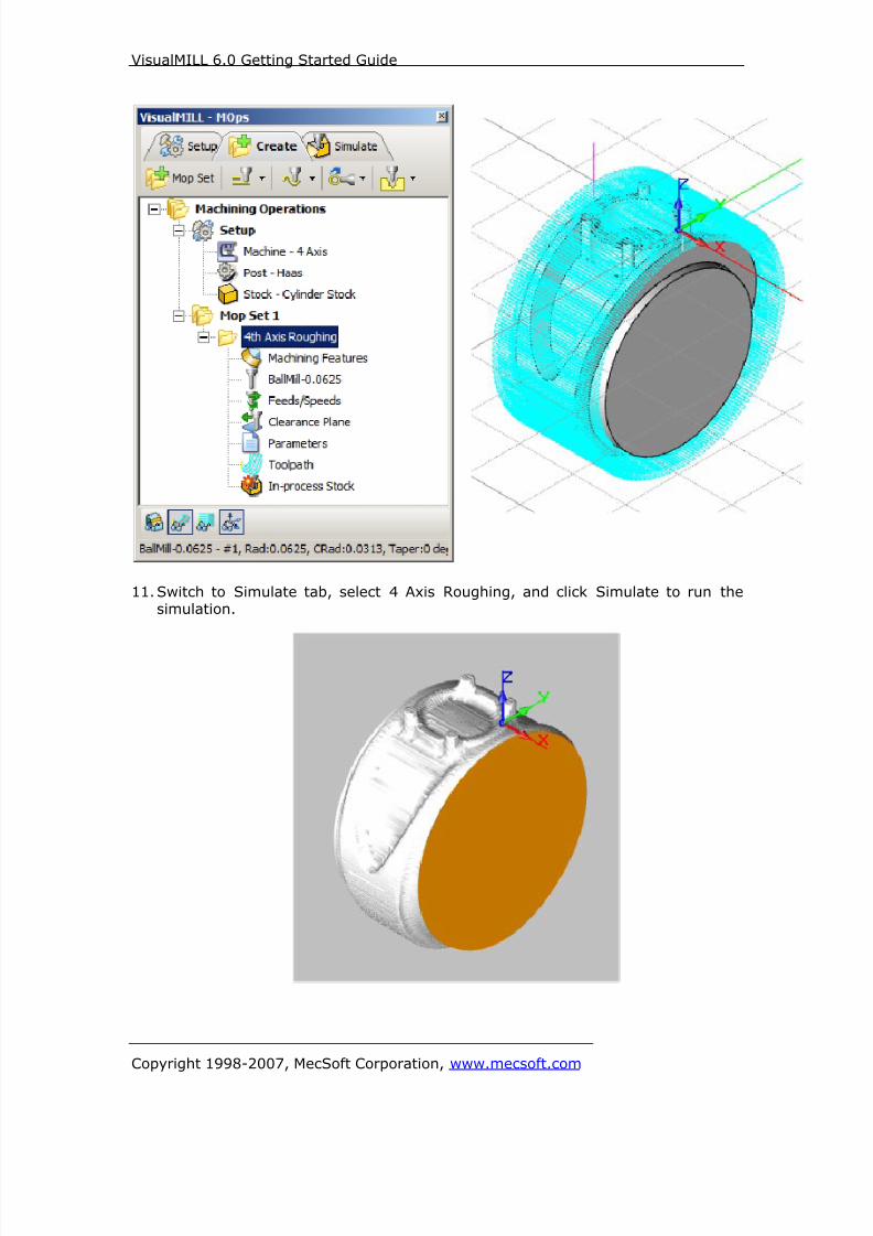
8/16/2019 Visual Mill Getting Started Guide
http://slidepdf.com/reader/full/visual-mill-getting-started-guide 367/411
VisualMILL 6.0 Getting Started Guide
Copyright 1998-2007, MecSoft Corporation, www.mecsoft.com
11. Switch to Simulate tab, select 4 Axis Roughing, and click Simulate to run thesimulation.
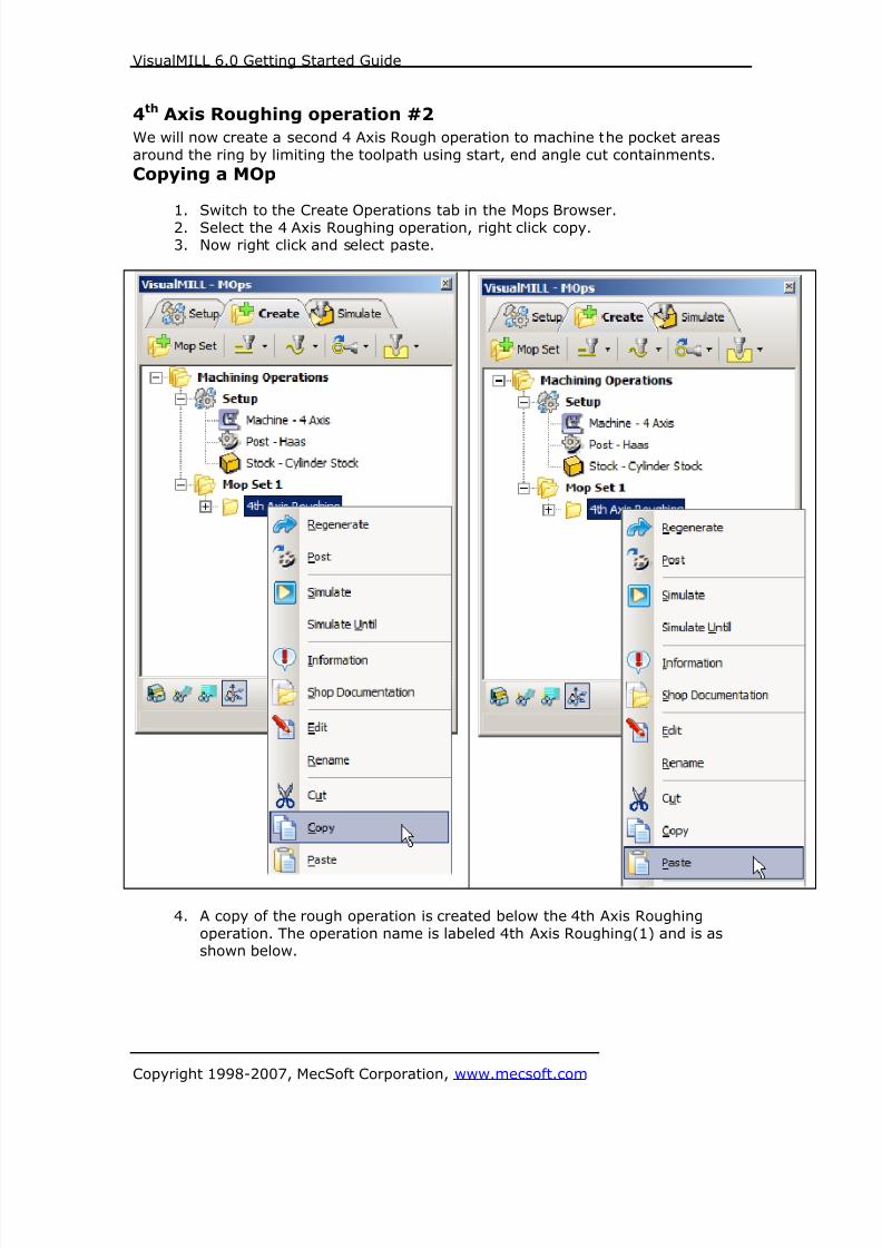
8/16/2019 Visual Mill Getting Started Guide
http://slidepdf.com/reader/full/visual-mill-getting-started-guide 368/411
VisualMILL 6.0 Getting Started Guide
Copyright 1998-2007, MecSoft Corporation, www.mecsoft.com
4th Axis Roughing operation #2
We will now create a second 4 Axis Rough operation to machine the pocket areas
around the ring by limiting the toolpath using start, end angle cut containments.
Copying a MOp
1. Switch to the Create Operations tab in the Mops Browser.
2. Select the 4 Axis Roughing operation, right click copy.3. Now right click and select paste.
4. A copy of the rough operation is created below the 4th Axis Roughing
operation. The operation name is labeled 4th Axis Roughing(1) and is asshown below.

8/16/2019 Visual Mill Getting Started Guide
http://slidepdf.com/reader/full/visual-mill-getting-started-guide 369/411
VisualMILL 6.0 Getting Started Guide
Copyright 1998-2007, MecSoft Corporation, www.mecsoft.com

8/16/2019 Visual Mill Getting Started Guide
http://slidepdf.com/reader/full/visual-mill-getting-started-guide 370/411
VisualMILL 6.0 Getting Started Guide
Copyright 1998-2007, MecSoft Corporation, www.mecsoft.com
Specify Cut Parameters5. Double click on 4th Axis Roughing(1) to edit the operation.
6. Switch to the Cut parameters tab and use the following parameters.a. Leave the global parameters and cut pattern unchanged
b. Under Cut Containment change the Start Angle (S) = -90, End
Angle (E) = 90, Uncheck Do not cut past.
7. Switch to the Step Down Control tab

8/16/2019 Visual Mill Getting Started Guide
http://slidepdf.com/reader/full/visual-mill-getting-started-guide 371/411
VisualMILL 6.0 Getting Started Guide
Copyright 1998-2007, MecSoft Corporation, www.mecsoft.com
Specify Step Down Control8. Use the Following Settings.
a. Cut Levels, Check Top (T) and specify Top (T) = 0.4 (as we hadlimited the toolpath to a radius = 0.4 on the 1st Rough operation),
Step Down Control (dR) = 75 (% Tool Diameter).
9. Click Generate. The 4 axis Roughing toolpath is now generated, and theOperation is listed under the VisualMILL-MOps browser.

8/16/2019 Visual Mill Getting Started Guide
http://slidepdf.com/reader/full/visual-mill-getting-started-guide 372/411
VisualMILL 6.0 Getting Started Guide
Copyright 1998-2007, MecSoft Corporation, www.mecsoft.com
10. Switch to Simulate tab, select 4 Axis Roughing, and click Simulate to runthe simulation.
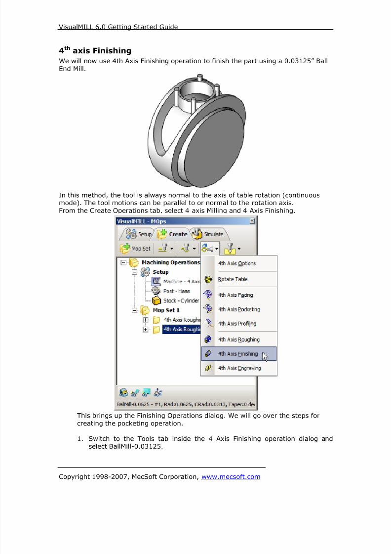
8/16/2019 Visual Mill Getting Started Guide
http://slidepdf.com/reader/full/visual-mill-getting-started-guide 373/411
VisualMILL 6.0 Getting Started Guide
Copyright 1998-2007, MecSoft Corporation, www.mecsoft.com
4th axis Finishing
We will now use 4th Axis Finishing operation to finish the part using a 0.03125” Ball
End Mill.
In this method, the tool is always normal to the axis of table rotation (continuousmode). The tool motions can be parallel to or normal to the rotation axis.
From the Create Operations tab, select 4 axis Milling and 4 Axis Finishing.
This brings up the Finishing Operations dialog. We will go over the steps for
creating the pocketing operation.
1. Switch to the Tools tab inside the 4 Axis Finishing operation dialog andselect BallMill-0.03125.

8/16/2019 Visual Mill Getting Started Guide
http://slidepdf.com/reader/full/visual-mill-getting-started-guide 374/411
VisualMILL 6.0 Getting Started Guide
Copyright 1998-2007, MecSoft Corporation, www.mecsoft.com
2. Click on the Feeds and Speeds tab and select Load From Tool. VisualMILLwill now get the feeds and speeds information that was set when the tool
was defined.
3. Switch to the Clearance Tab and set the Clearance Plane Definition toAutomatic and Cut Transfer Method to Clearance Plane.
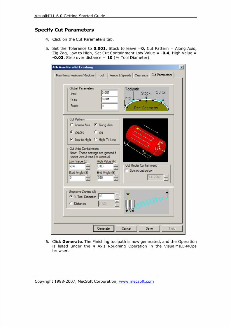
8/16/2019 Visual Mill Getting Started Guide
http://slidepdf.com/reader/full/visual-mill-getting-started-guide 375/411
VisualMILL 6.0 Getting Started Guide
Copyright 1998-2007, MecSoft Corporation, www.mecsoft.com
Specify Cut Parameters
4. Click on the Cut Parameters tab.
5. Set the Tolerance to 0.001, Stock to leave =0, Cut Pattern = Along Axis,Zig Zag, Low to High, Set Cut Containment Low Value = -0.4, High Value =
-0.03, Step over distance = 10 (% Tool Diameter).
6. Click Generate. The Finishing toolpath is now generated, and the Operation
is listed under the 4 Axis Roughing Operation in the VisualMILL-MOpsbrowser.

8/16/2019 Visual Mill Getting Started Guide
http://slidepdf.com/reader/full/visual-mill-getting-started-guide 376/411
VisualMILL 6.0 Getting Started Guide
Copyright 1998-2007, MecSoft Corporation, www.mecsoft.com
7. Switch to Simulate tab, select 4 Axis Finishing, and click Simulate to run the
simulation.

8/16/2019 Visual Mill Getting Started Guide
http://slidepdf.com/reader/full/visual-mill-getting-started-guide 377/411
VisualMILL 6.0 Getting Started Guide
Copyright 1998-2007, MecSoft Corporation, www.mecsoft.com
Post Processing
1. Select Machining Operations from the Create Operations tab and right click
and select post process.
2. Specify the File Name as Ring2.nc and click save.
The post by default is set to Haas as specified under the Post processor setup. You
can change the post processor by selecting a different one from the drop down menuin the list. The posted g code by default will be saved to the folder where the part fileis located.
End of Tutorial 12!

8/16/2019 Visual Mill Getting Started Guide
http://slidepdf.com/reader/full/visual-mill-getting-started-guide 378/411
VisualMILL 6.0 Getting Started Guide
Copyright 1998-2007, MecSoft Corporation, www.mecsoft.com
Tutorial 13: Pocketing and Drilling on a Ring
8/16/2019 Visual Mill Getting Started Guide
http://slidepdf.com/reader/full/visual-mill-getting-started-guide 379/411
VisualMILL 6.0 Getting Started Guide
Copyright 1998-2007, MecSoft Corporation, www.mecsoft.com
Introduction
This tutorial is intended to describe the 4 axis pocketing and hole making operations.
Pocketing machines closed regions as if they were pockets - completely enclosed by
inner and outer regions. The tool cannot go beyond the outer region, and cannot gowithin inner regions. This is unlike Facing, in which the outermost region is
considered to enclose material to be removed. Hole making operations are used tocreate holes in a part; the hole types varying from simple drill holes, counter sunk
holes, through holes to tapped and bored holes. Here you will learn to drill simpleholes.
The stepped instructions are accompanied by explanatory and introductory text.
Reading this text will help you understand the tutorial methodology and provideinformation about additional options available.
Don’t forget to save your work periodically! You may want to save the file under a
different name so that the original file will be preserved.
Strategy to machine the part
• We will machine the ring completely using 4 axis-machining operations.
• The part itself will be machined out of a cylindrical blank.
• The stock will be held to the machine table using a rotary chuck.
• The part will be machined using a 0.0625” Flat End Mill and 0.125” Standard
Drill
Main Programming StepsIn creating programs for each setup, the following steps will be followed:
• Create the Stock geometry
• Set the Machine zero point or Locate geometry with respect to the machine
coordinates.
• Set the rotary axis and rotary center.• Create / Select the tool used for machining
• Set the feeds and speeds
• Set the clearance plane for the non-cutting transfer moves of the cutter
• Select the machining operations and set the parameters
• Generate the toolpath
• Simulate the toolpath.
You may have to repeat either all or part of these steps for subsequent operations.
Preparing the part for Machining
Loading the Part Model
“Part” refers to the geometry that represents the final manufactured product. Youcan create parts within VisualMILL, but it is more typical to import geometry created
in another CAD system.
To load a part:
1. Select File / Open from the Menu, or click the Open icon from the
Standard bar.

8/16/2019 Visual Mill Getting Started Guide
http://slidepdf.com/reader/full/visual-mill-getting-started-guide 380/411
VisualMILL 6.0 Getting Started Guide
Copyright 1998-2007, MecSoft Corporation, www.mecsoft.com
2. From the Open dialog box, select the 4AxisPocketing_1.vcp file from the
Tutorials folder in the VisualMILL 6.0 installation folder. (C:\Program
Files\MecSoft Corporation\VisualCAM 1.0\Plug-ins\VisualMILL 6.0\Tutorials)
The imported part appears as shown below

8/16/2019 Visual Mill Getting Started Guide
http://slidepdf.com/reader/full/visual-mill-getting-started-guide 381/411
VisualMILL 6.0 Getting Started Guide
Copyright 1998-2007, MecSoft Corporation, www.mecsoft.com
Setup Tab
1. Go to the VisualMILL- MOps browser and click on the Setup tab.
2. Select Machine Setup from the setup tab.
3. Set the Machine type to 4 axis and Rotary Axis to X axis. For most
controllers rotation along X represents A axis and rotation along Yrepresents B axis. We will set the Rotary Center once we determine the
Machine Zero.
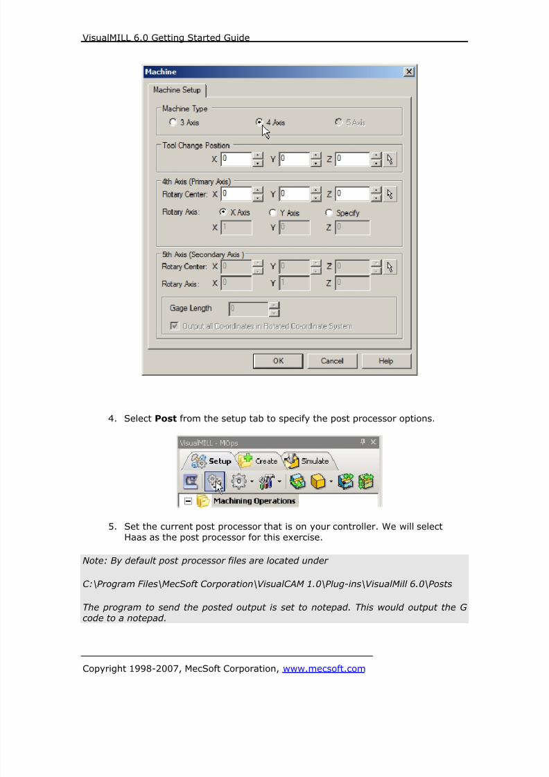
8/16/2019 Visual Mill Getting Started Guide
http://slidepdf.com/reader/full/visual-mill-getting-started-guide 382/411
VisualMILL 6.0 Getting Started Guide
Copyright 1998-2007, MecSoft Corporation, www.mecsoft.com
4. Select Post from the setup tab to specify the post processor options.
5. Set the current post processor that is on your controller. We will selectHaas as the post processor for this exercise.
Note: By default post processor files are located under
C:\Program Files\MecSoft Corporation\VisualCAM 1.0\Plug-ins\VisualMill 6.0\Posts
The program to send the posted output is set to notepad. This would output the Gcode to a notepad.

8/16/2019 Visual Mill Getting Started Guide
http://slidepdf.com/reader/full/visual-mill-getting-started-guide 383/411
VisualMILL 6.0 Getting Started Guide
Copyright 1998-2007, MecSoft Corporation, www.mecsoft.com
Create Stock Geometry
1. Select Create/Load stock from the setup tab and create a Cylinder Stock.
2. This brings up the Cylinder Stock parameters. Set the Axis (rotary) = X,
Radius = 2” and Length (L) = 1”. Leave the other parameters as default
and click OK.
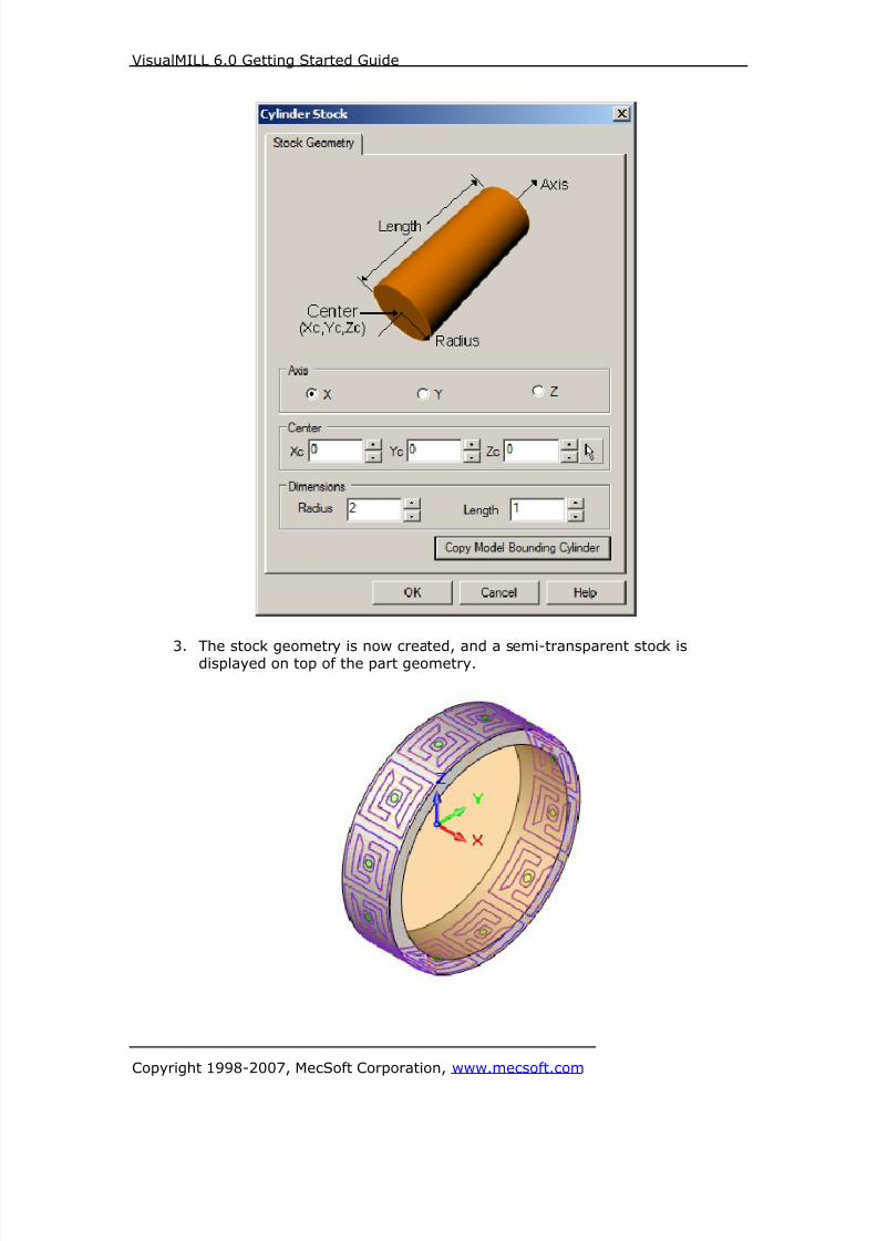
8/16/2019 Visual Mill Getting Started Guide
http://slidepdf.com/reader/full/visual-mill-getting-started-guide 384/411
VisualMILL 6.0 Getting Started Guide
Copyright 1998-2007, MecSoft Corporation, www.mecsoft.com
3. The stock geometry is now created, and a semi-transparent stock isdisplayed on top of the part geometry.

8/16/2019 Visual Mill Getting Started Guide
http://slidepdf.com/reader/full/visual-mill-getting-started-guide 385/411
VisualMILL 6.0 Getting Started Guide
Copyright 1998-2007, MecSoft Corporation, www.mecsoft.com
4. You must switch the simulation model to Polygonal model to run 4 axis
simulations. Select Preferences->Simulation Preferences from the Setup
Tab and switch the simulation model to Polygonal if set to Voxel.
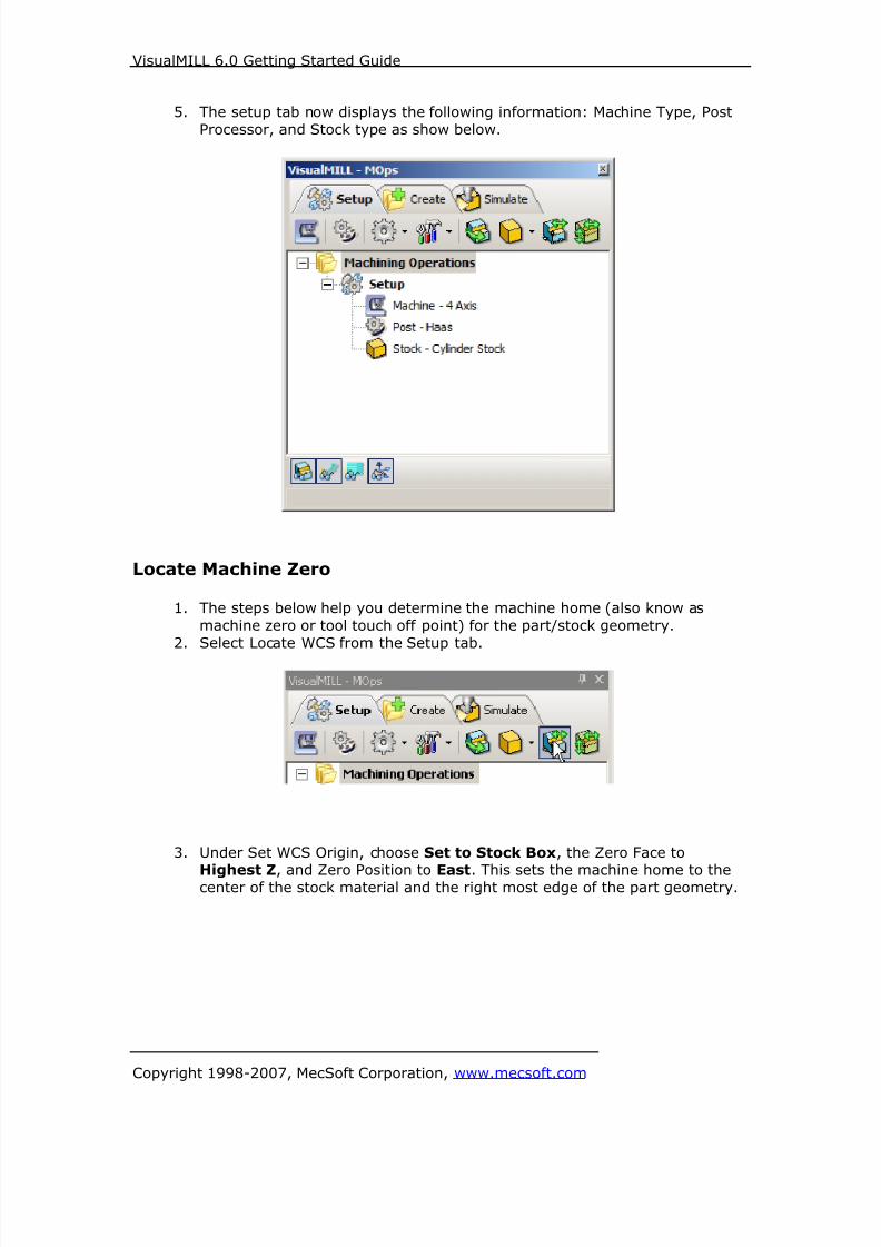
8/16/2019 Visual Mill Getting Started Guide
http://slidepdf.com/reader/full/visual-mill-getting-started-guide 386/411
VisualMILL 6.0 Getting Started Guide
Copyright 1998-2007, MecSoft Corporation, www.mecsoft.com
5. The setup tab now displays the following information: Machine Type, Post
Processor, and Stock type as show below.
Locate Machine Zero
1. The steps below help you determine the machine home (also know as
machine zero or tool touch off point) for the part/stock geometry.
2. Select Locate WCS from the Setup tab.
3. Under Set WCS Origin, choose Set to Stock Box, the Zero Face to
Highest Z, and Zero Position to East. This sets the machine home to thecenter of the stock material and the right most edge of the part geometry.

8/16/2019 Visual Mill Getting Started Guide
http://slidepdf.com/reader/full/visual-mill-getting-started-guide 387/411
VisualMILL 6.0 Getting Started Guide
Copyright 1998-2007, MecSoft Corporation, www.mecsoft.com

8/16/2019 Visual Mill Getting Started Guide
http://slidepdf.com/reader/full/visual-mill-getting-started-guide 388/411
VisualMILL 6.0 Getting Started Guide
Copyright 1998-2007, MecSoft Corporation, www.mecsoft.com
Note: You can change the stock model transparency under standard mode by
selecting Simulation Preferences that is located at the bottom of the MOps browser.
Align Part and StockDuring this step, we will align the part inside the stock geometry.
1. Select Align Part and Stock from the Setup tab
In this step, we will position the part to the center of the stock in XY and Z.
2. Use the following settings, Object to Move: Move Part, Z alignment:
Center and XY Alignment: Center.
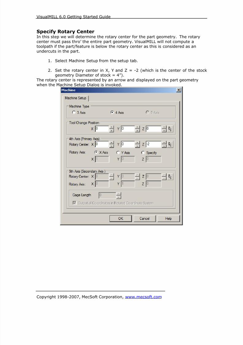
8/16/2019 Visual Mill Getting Started Guide
http://slidepdf.com/reader/full/visual-mill-getting-started-guide 389/411
VisualMILL 6.0 Getting Started Guide
Copyright 1998-2007, MecSoft Corporation, www.mecsoft.com
Specify Rotary CenterIn this step we will determine the rotary center for the part geometry. The rotary
center must pass thro’ the entire part geometry. VisualMILL will not compute atoolpath if the part/feature is below the rotary center as this is considered as an
undercuts in the part.
1. Select Machine Setup from the setup tab.
2. Set the rotary center in X, Y and Z = -2 (which is the center of the stockgeometry Diameter of stock = 4”).
The rotary center is represented by an arrow and displayed on the part geometry
when the Machine Setup Dialog is invoked.

8/16/2019 Visual Mill Getting Started Guide
http://slidepdf.com/reader/full/visual-mill-getting-started-guide 390/411
VisualMILL 6.0 Getting Started Guide
Copyright 1998-2007, MecSoft Corporation, www.mecsoft.com
Create Tools
To machine the above part, we will now create a 0.125” Drill (Standard Drill) and a
0.0625” Flat End Mill.
1. Go to the VisualMILL-Tools browser that is located below the VisualMILL-
MOps browser and select Create/Edit Tools. Select the Tool Type to Drill.
2. Set the tool name as Drill-0.125, Tool Diameter = 0.125, Tip Angle =120. Under the Properties tab set Tool Number = 1.

8/16/2019 Visual Mill Getting Started Guide
http://slidepdf.com/reader/full/visual-mill-getting-started-guide 391/411
VisualMILL 6.0 Getting Started Guide
Copyright 1998-2007, MecSoft Corporation, www.mecsoft.com
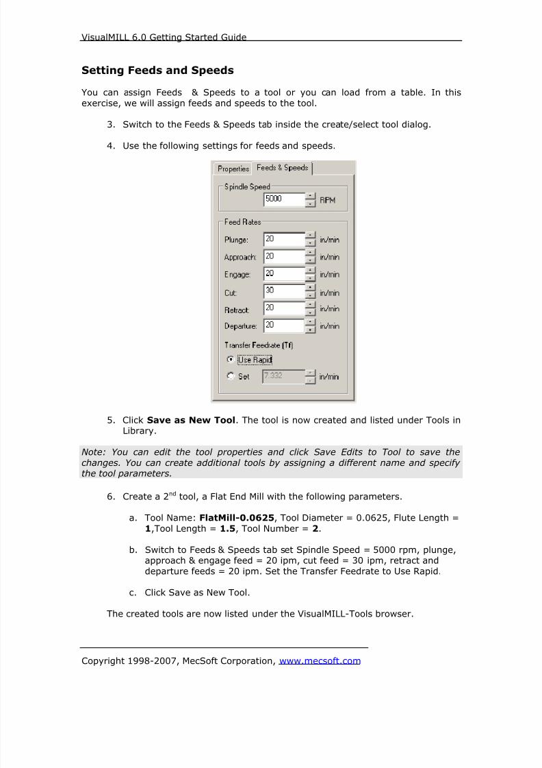
8/16/2019 Visual Mill Getting Started Guide
http://slidepdf.com/reader/full/visual-mill-getting-started-guide 392/411
VisualMILL 6.0 Getting Started Guide
Copyright 1998-2007, MecSoft Corporation, www.mecsoft.com
Setting Feeds and Speeds
You can assign Feeds & Speeds to a tool or you can load from a table. In this
exercise, we will assign feeds and speeds to the tool.
3. Switch to the Feeds & Speeds tab inside the create/select tool dialog.
4. Use the following settings for feeds and speeds.
5. Click Save as New Tool. The tool is now created and listed under Tools inLibrary.
Note: You can edit the tool properties and click Save Edits to Tool to save the
changes. You can create additional tools by assigning a different name and specifythe tool parameters.
6. Create a 2nd tool, a Flat End Mill with the following parameters.
a. Tool Name: FlatMill-0.0625, Tool Diameter = 0.0625, Flute Length =
1,Tool Length = 1.5, Tool Number = 2.
b. Switch to Feeds & Speeds tab set Spindle Speed = 5000 rpm, plunge,approach & engage feed = 20 ipm, cut feed = 30 ipm, retract and
departure feeds = 20 ipm. Set the Transfer Feedrate to Use Rapid.
c. Click Save as New Tool.
The created tools are now listed under the VisualMILL-Tools browser.
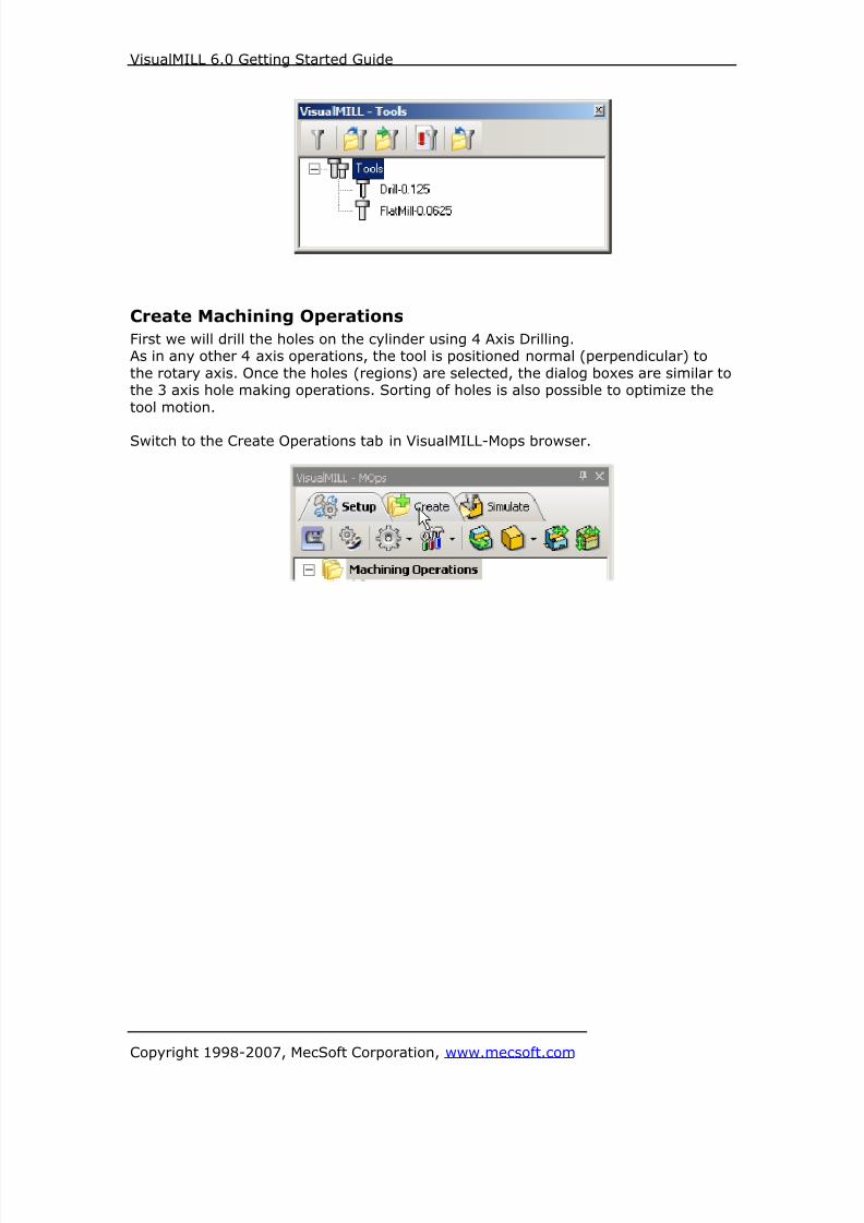
8/16/2019 Visual Mill Getting Started Guide
http://slidepdf.com/reader/full/visual-mill-getting-started-guide 393/411
VisualMILL 6.0 Getting Started Guide
Copyright 1998-2007, MecSoft Corporation, www.mecsoft.com
Create Machining Operations
First we will drill the holes on the cylinder using 4 Axis Drilling.As in any other 4 axis operations, the tool is positioned normal (perpendicular) to
the rotary axis. Once the holes (regions) are selected, the dialog boxes are similar tothe 3 axis hole making operations. Sorting of holes is also possible to optimize the
tool motion.
Switch to the Create Operations tab in VisualMILL-Mops browser.
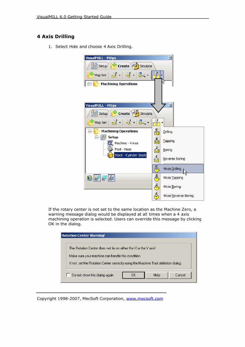
8/16/2019 Visual Mill Getting Started Guide
http://slidepdf.com/reader/full/visual-mill-getting-started-guide 394/411
VisualMILL 6.0 Getting Started Guide
Copyright 1998-2007, MecSoft Corporation, www.mecsoft.com
4 Axis Drilling
1. Select Hole and choose 4 Axis Drilling.
If the rotary center is not set to the same location as the Machine Zero, a
warning message dialog would be displayed at all times when a 4 axismachining operation is selected. Users can override this message by clicking
OK in the dialog.

8/16/2019 Visual Mill Getting Started Guide
http://slidepdf.com/reader/full/visual-mill-getting-started-guide 395/411
VisualMILL 6.0 Getting Started Guide
Copyright 1998-2007, MecSoft Corporation, www.mecsoft.com
Note: You can check Do no show this dialog again to stop the warning message
appearing again when you create/edit a 4 axis machining operation.
2. This brings up the 4 Axis Drilling Operation Dialog. We will now go over thesteps for creating the toolpath.
Select Hole Features
3. Go to the Machining Features/ Regions tab and click Hole Features.
4. Now, select the 12 circles around the part (represented in green color). Youcan also use the Select tool from the menu bar and use Select->By Layer
and choose Layer 04.
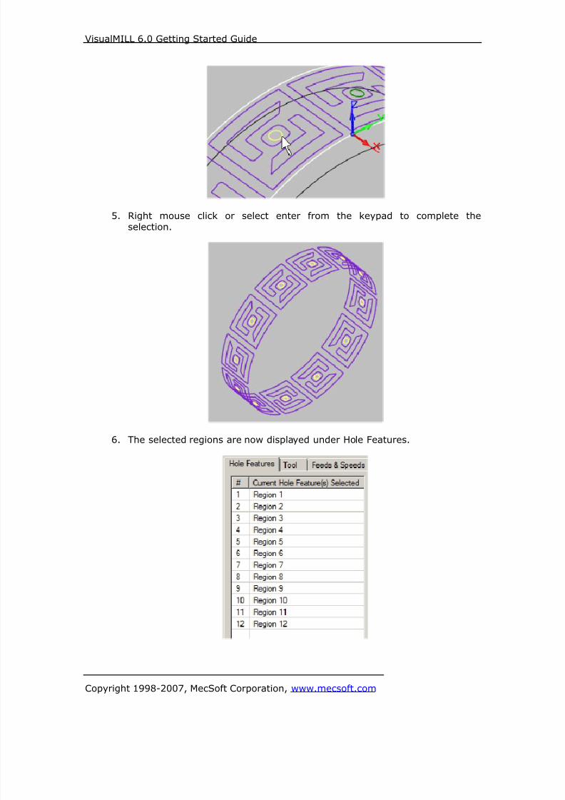
8/16/2019 Visual Mill Getting Started Guide
http://slidepdf.com/reader/full/visual-mill-getting-started-guide 396/411
VisualMILL 6.0 Getting Started Guide
Copyright 1998-2007, MecSoft Corporation, www.mecsoft.com
5. Right mouse click or select enter from the keypad to complete theselection.
6. The selected regions are now displayed under Hole Features.
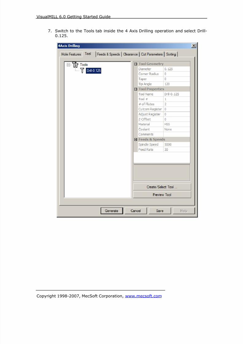
8/16/2019 Visual Mill Getting Started Guide
http://slidepdf.com/reader/full/visual-mill-getting-started-guide 397/411
VisualMILL 6.0 Getting Started Guide
Copyright 1998-2007, MecSoft Corporation, www.mecsoft.com
7. Switch to the Tools tab inside the 4 Axis Drilling operation and select Drill-
0.125.

8/16/2019 Visual Mill Getting Started Guide
http://slidepdf.com/reader/full/visual-mill-getting-started-guide 398/411
VisualMILL 6.0 Getting Started Guide
Copyright 1998-2007, MecSoft Corporation, www.mecsoft.com
8. Click on the Feeds and Speeds tab and select Load From Tool. VisualMILL
will now get the feeds and speeds information that was set when the toolwas defined.
9. Switch to Clearance tab and set the Clearance Plane Definition to Stock Max
R + Dist = 0.25. Set the cut transfer method to Clearance Plane.

8/16/2019 Visual Mill Getting Started Guide
http://slidepdf.com/reader/full/visual-mill-getting-started-guide 399/411
VisualMILL 6.0 Getting Started Guide
Copyright 1998-2007, MecSoft Corporation, www.mecsoft.com

8/16/2019 Visual Mill Getting Started Guide
http://slidepdf.com/reader/full/visual-mill-getting-started-guide 400/411
VisualMILL 6.0 Getting Started Guide
Copyright 1998-2007, MecSoft Corporation, www.mecsoft.com
Specify Cut Parameters
10. Click on the Cut Parameters tab.
11. Set the Drill Type = Standard Drill, Drill Depth = 0.1, Check Add Tool tipto Drill Depth and Approach Distance = 0.1
12. Switch to Sorting tab in the 4 Axis Drilling dialog.
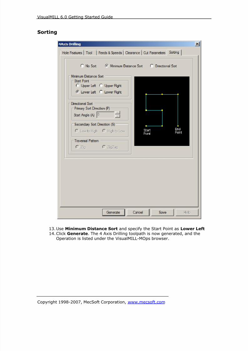
8/16/2019 Visual Mill Getting Started Guide
http://slidepdf.com/reader/full/visual-mill-getting-started-guide 401/411
VisualMILL 6.0 Getting Started Guide
Copyright 1998-2007, MecSoft Corporation, www.mecsoft.com
Sorting
13. Use Minimum Distance Sort and specify the Start Point as Lower Left 14. Click Generate. The 4 Axis Drilling toolpath is now generated, and the
Operation is listed under the VisualMILL-MOps browser.
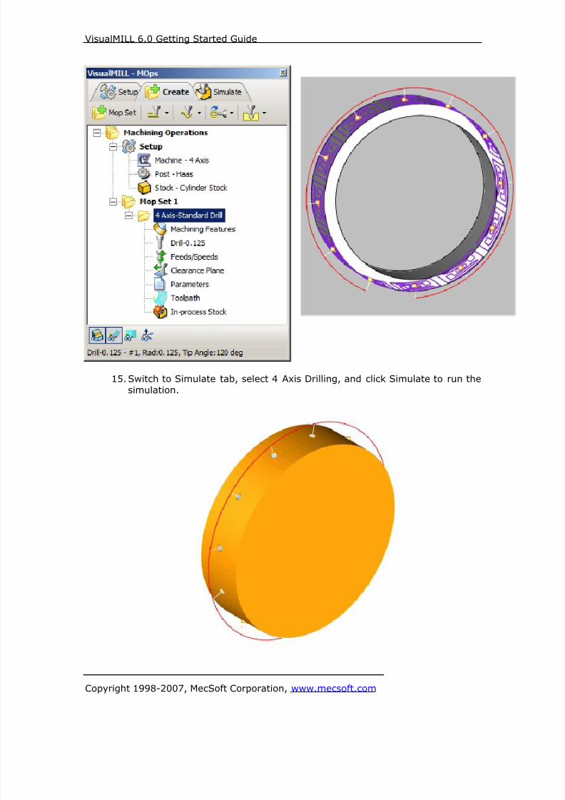
8/16/2019 Visual Mill Getting Started Guide
http://slidepdf.com/reader/full/visual-mill-getting-started-guide 402/411
VisualMILL 6.0 Getting Started Guide
Copyright 1998-2007, MecSoft Corporation, www.mecsoft.com
15. Switch to Simulate tab, select 4 Axis Drilling, and click Simulate to run the
simulation.
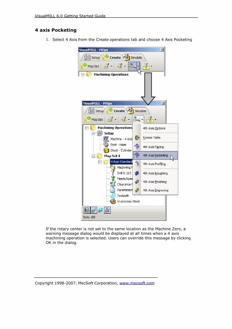
8/16/2019 Visual Mill Getting Started Guide
http://slidepdf.com/reader/full/visual-mill-getting-started-guide 403/411
VisualMILL 6.0 Getting Started Guide
Copyright 1998-2007, MecSoft Corporation, www.mecsoft.com
4 axis Pocketing
1. Select 4 Axis from the Create operations tab and choose 4 Axis Pocketing
If the rotary center is not set to the same location as the Machine Zero, awarning message dialog would be displayed at all times when a 4 axis
machining operation is selected. Users can override this message by clickingOK in the dialog.

8/16/2019 Visual Mill Getting Started Guide
http://slidepdf.com/reader/full/visual-mill-getting-started-guide 404/411
VisualMILL 6.0 Getting Started Guide
Copyright 1998-2007, MecSoft Corporation, www.mecsoft.com
Note: You can check Do no show this dialog again to stop the warning messageappearing again when you create/edit a 4 axis machining operation.
2. This brings up the 4 Axis Pocketing Operation Dialog. We will now go over
the steps for creating the toolpath.
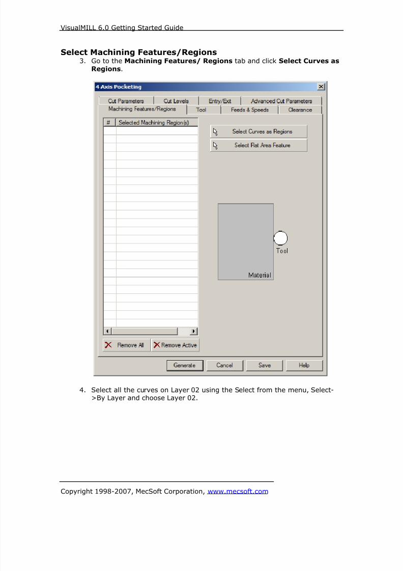
8/16/2019 Visual Mill Getting Started Guide
http://slidepdf.com/reader/full/visual-mill-getting-started-guide 405/411
VisualMILL 6.0 Getting Started Guide
Copyright 1998-2007, MecSoft Corporation, www.mecsoft.com
Select Machining Features/Regions3. Go to the Machining Features/ Regions tab and click Select Curves as
Regions.
4. Select all the curves on Layer 02 using the Select from the menu, Select-
>By Layer and choose Layer 02.

8/16/2019 Visual Mill Getting Started Guide
http://slidepdf.com/reader/full/visual-mill-getting-started-guide 406/411
VisualMILL 6.0 Getting Started Guide
Copyright 1998-2007, MecSoft Corporation, www.mecsoft.com
5. Right mouse click or select enter from the keypad to complete theselection.
6. The selected regions are now displayed under Machining Regions.
7. Switch to the Tools tab inside the 4 axis pocketing operation and selectFlatMill-0.0625.

8/16/2019 Visual Mill Getting Started Guide
http://slidepdf.com/reader/full/visual-mill-getting-started-guide 407/411
VisualMILL 6.0 Getting Started Guide
Copyright 1998-2007, MecSoft Corporation, www.mecsoft.com
8. Click on the Feeds and Speeds tab and select Load From Tool. VisualMILL
will now get the feeds and speeds information that was set when the toolwas defined.
9. Switch to the Clearance Tab and set the Clearance Plane Definition to
Automatic and Cut Transfer Method to Clearance Plane.

8/16/2019 Visual Mill Getting Started Guide
http://slidepdf.com/reader/full/visual-mill-getting-started-guide 408/411
VisualMILL 6.0 Getting Started Guide
Copyright 1998-2007, MecSoft Corporation, www.mecsoft.com
Specify Cut Parameters
10. Click on the Cut Parameters tab.
11. Set Tolerance = 0.001, Stock = 0, Cut Pattern = Offset Cuts, CutDirection = Mixed, Start Point = Inside, Step Distance = 25% (Tool
Diameter), Check Corner Cleanup.
12. Switch to Cut Levels Tab.
13. Use the following Settings
a. Location of Cut Geometry – At Top.
b. Total Cut Depth = 0.1, Rough Depth = 0.1
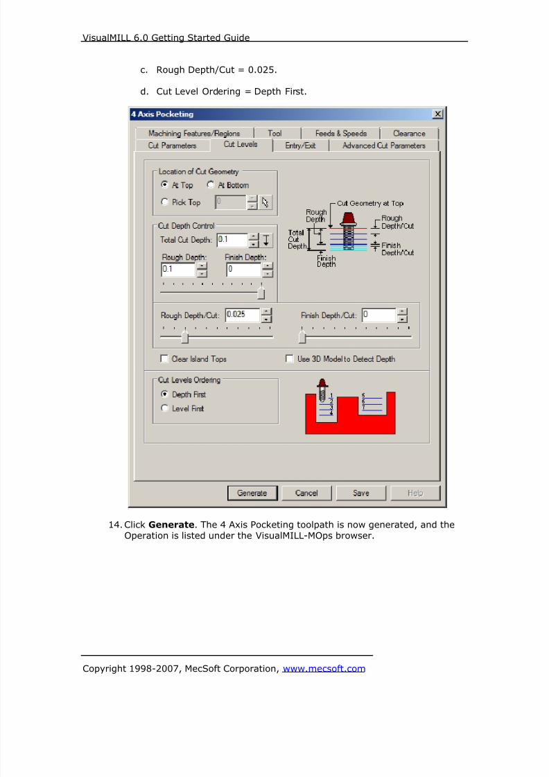
8/16/2019 Visual Mill Getting Started Guide
http://slidepdf.com/reader/full/visual-mill-getting-started-guide 409/411
VisualMILL 6.0 Getting Started Guide
Copyright 1998-2007, MecSoft Corporation, www.mecsoft.com
c. Rough Depth/Cut = 0.025.
d. Cut Level Ordering = Depth First.
14. Click Generate. The 4 Axis Pocketing toolpath is now generated, and the
Operation is listed under the VisualMILL-MOps browser.
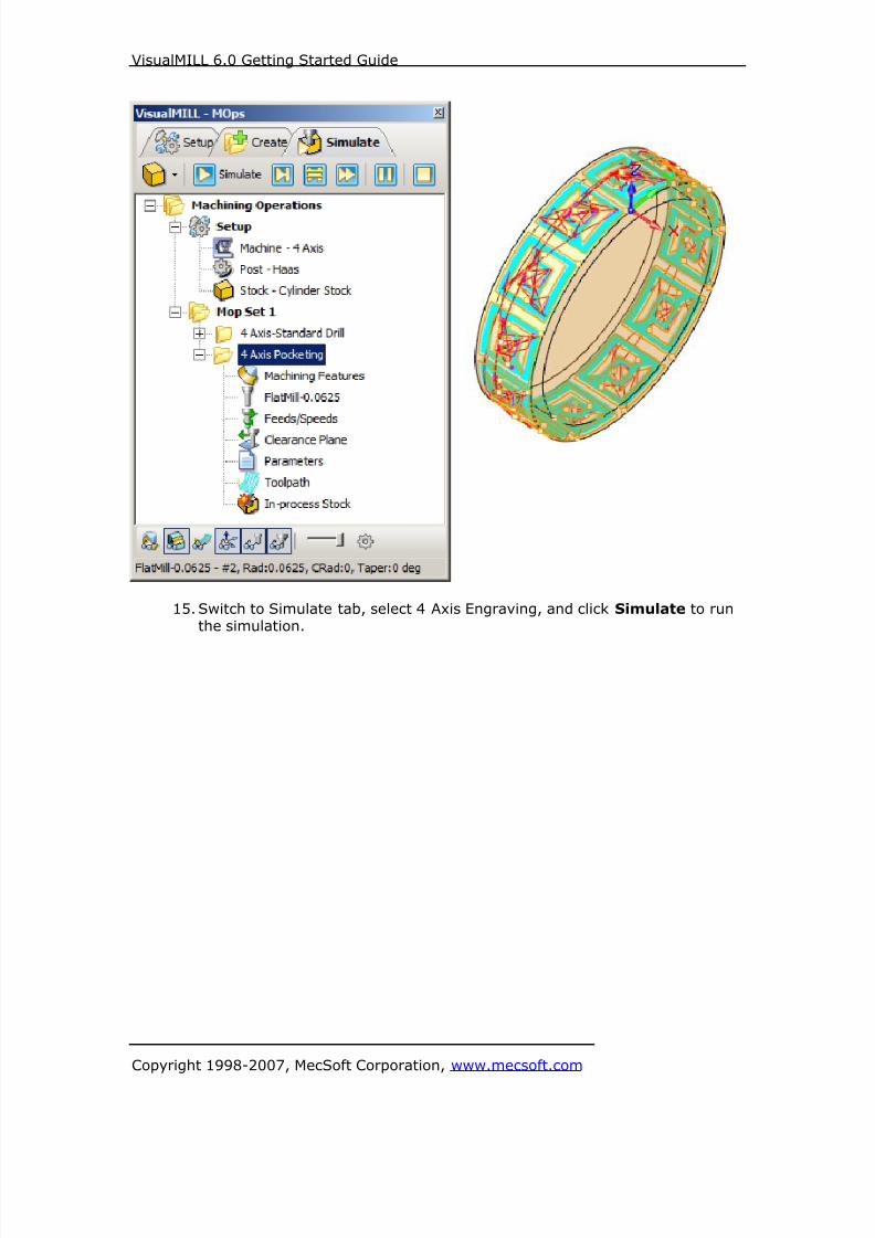
8/16/2019 Visual Mill Getting Started Guide
http://slidepdf.com/reader/full/visual-mill-getting-started-guide 410/411
VisualMILL 6.0 Getting Started Guide
Copyright 1998-2007, MecSoft Corporation, www.mecsoft.com
15. Switch to Simulate tab, select 4 Axis Engraving, and click Simulate to runthe simulation.

8/16/2019 Visual Mill Getting Started Guide
http://slidepdf.com/reader/full/visual-mill-getting-started-guide 411/411
VisualMILL 6.0 Getting Started Guide
Post Processing
1. Select Machining Operations from the Create Operations tab and right clickand select post process.