Embed Size (px)
Citation preview
VISTA50P-PR 8/95 (See Instructions N5944-6)
VISTA-50PVISTA-50PUL
PARTITIONED SECURITY SYSTEMwith SCHEDULING
Quick StartStep-by-Step Programming Procedure
Single And Multiple Partition Programming FormsSystem Worksheets

Ð 2Ð
Ð 3 Ð
TABLE OF CONTENTS
SUMMARY OF PROGRAMMING COMMANDS....................................................................................... 2
RECOMMENDED PROGRAMMING PROCEDURE................................................................................. 3
PROGRAM FIELD CATEGORIES ............................................................................................................. 5
VISTA-50P/PUL SINGLE PARTITION PROGRAMMING FORM.............................................................. 6
VISTA-50P/PUL MULTIPLE-PARTITION PROGRAMMING FORM ....................................................... 11
PROGRAMMING WITH #93 MENU MODE............................................................................................. 17
SYSTEM LAYOUT WORKSHEETS ........................................................................................................ 18
The purpose of this document is to provide a quick and easy way to program your entire system. Arecommended programming procedure is included, followed by a list of program fields with thecorresponding program group they belong to (system-wide, partition-specific, scheduling, etc.). Twoprogram forms are included, one for a single-partition system, and the other for a multiple partition system.If you are setting up a single-partition system, the partition-specific fields become system-wide fields.
Following the program forms are system layout worksheets. We recommend that you use these sheetsto plan your system before programming is performed. If you need further information about specificprogramming options, see the VISTA-50P/VISTA-50PUL INSTALLATION INSTRUCTIONS.
Two programming forms are provided: Single Partition Form and Multiple-Partition Form
• Make sure that one two-line alpha keypad is connected to the control and is set to deviceaddress "00."
Single Partition System• The system default is for a single partition system. Use the VISTA-50P/PUL SINGLE
PARTITION PROGRAMMING FORM beginning on page 7 when programming for singlepartition usage. Follow the steps outlined on page 4 of this document for proper programmingprocedure.
Multiple-Partition System• You must enter the number of partitions you are using in data field 2*00 to set the system for
multiple partitions. Use the VISTA-50P/PUL MULTIPLE-PARTITION PROGRAMMING FORMbeginning on page 13 when programming the system for multiple partitions. Follow the stepsoutlined on page 4 of this document for proper programming procedure.
SUMMARY OF PROGRAMMING COMMANDS¥ To enter program mode, enter installer code + [8] + [0] + [0]¥ To set standard defaults, press *97¥ To set communication defaults, press *94 + one of the following: *80=low speed; *81=Ademco
Express; *82=Ademco High Speed; *83=Ademco's Contact ID¥ To change to next page of program fields, press *94¥ To return to previous set of fields, press *99¥ To erase account & phone number field entries, press [*] + field number + [*]¥ To assign zone descriptors, press #93 + follow menu prompts¥ To add custom words, press #93 + follow menu prompts¥ To enter Installer's Message, press #93 + follow menu prompts¥ To exit program mode, press *99 OR *98: *99 allows re-access to programming mode by installer code.
*98 prevents re-access to programming mode by installer code.
Standard default (*97) values are shown in brackets [ ], otherwise default = 0.
Ð 4Ð
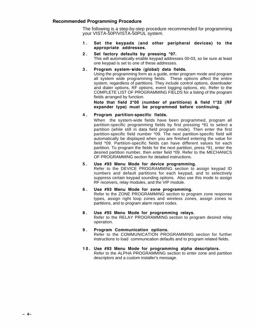
Recommended Programming Procedure
The following is a step-by-step procedure recommended for programmingyour VISTA-50P/VISTA-50PUL system.
1 . Set the keypads (and other peripheral devices) to theappropriate addresses.
2 . Set factory defaults by pressing *97.This will automatically enable keypad addresses 00-03, so be sure at leastone keypad is set to one of these addresses.
3 . Program system-wide (global) data fields.Using the programming form as a guide, enter program mode and programall system wide programming fields. These options affect the entiresystem, regardless of partitions. They include control options, downloaderand dialer options, RF options, event logging options, etc. Refer to theCOMPLETE LIST OF PROGRAMMING FIELDS for a listing of the programfields arranged by function.Note that field 2*00 (number of partitions) & field 1*32 (RFexpander type) must be programmed before continuing.
4 . Program partition-specific fields.When the system-wide fields have been programmed, program allpartition-specific programming fields by first pressing *91 to select apartition (while still in data field program mode). Then enter the firstpartition-specific field number *09. The next partition-specific field willautomatically be displayed when you are finished entering the value forfield *09. Partition-specific fields can have different values for eachpartition. To program the fields for the next partition, press *91, enter thedesired partition number, then enter field *09. Refer to the MECHANICSOF PROGRAMMING section for detailed instructions.
5 . Use #93 Menu Mode for device programming.Refer to the DEVICE PROGRAMMING section to assign keypad IDnumbers and default partitions for each keypad, and to selectivelysuppress certain keypad sounding options. Also use this mode to assignRF receivers, relay modules, and the VIP module.
6 . Use #93 Menu Mode for zone programming.Refer to the ZONE PROGRAMMING section to program zone responsetypes, assign right loop zones and wireless zones, assign zones topartitions, and to program alarm report codes.
8 . Use #93 Menu Mode for programming relays.Refer to the RELAY PROGRAMMING section to program desired relayoperation.
9 . Program Communication options.Refer to the COMMUNICATION PROGRAMMING section for furtherinstructions to load communication defaults and to program related fields.
1 0 . Use #93 Menu Mode for programming alpha descriptors.Refer to the ALPHA PROGRAMMING section to enter zone and partitiondescriptors and a custom installer's message.
Ð 5 Ð
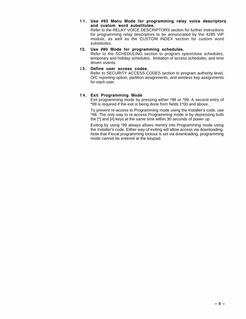
1 1 . Use #93 Menu Mode for programming relay voice descriptorsand custom word substitutes.Refer to the RELAY VOICE DESCRIPTORS section for further instructionsfor programming relay descriptors to be annunciated by the 4285 VIPmodule, as well as the CUSTOM INDEX section for custom wordsubstitutes.
12. Use #80 Mode for programming schedules.Refer to the SCHEDULING section to program open/close schedules,temporary and holiday schedules, limitation of access schedules, and timedriven events.
13 . Define user access codes.Refer to SECURITY ACCESS CODES section to program authority level,O/C reporting option, partition assignments, and wireless key assignmentsfor each user.
1 4 . Exit Programming ModeExit programming mode by pressing either *98 or *99. A second entry of*99 is required if the exit is being done from fields 1*00 and above.
To prevent re-access to Programming mode using the Installer's code, use*98. The only way to re-access Programming mode is by depressing boththe [*] and [#] keys at the same time within 30 seconds of power up.
Exiting by using *99 always allows reentry into Programming mode usingthe Installer's code. Either way of exiting will allow access via downloading.Note that if local programming lockout is set via downloading, programmingmode cannot be entered at the keypad.

Ð 6Ð
PROGRAM FIELD CATEGORIESIn the following pages, the programming fields have been arranged by category. Use this index to cross referencethe numerical ordered fields on the programming form.
Field Group *00 System-Wide*02 #93 Menu Mode*03 #93 Menu Mode*04 #93 Menu Mode*05 #93 Menu Mode*09 Partition-Specific*10 Partition-Specific*11 Partition-Specific*12 Partition-Specific*13 Partition-Specific*14 System-Wide*15 System-Wide*16 Partition-Specific*17 System-Wide*18 System-Wide*19 System-Wide*20 System-Wide*21 System-Wide*22 Partition-Specific*23 Partition-Specific*24 System-Wide*25 System-Wide*26 Communications*27 Communications*28 System-Wide*29 Partition-Specific*30 Communications*31 Communications*32 Partition-Specific*33 Communications*34 Communications*35 System-Wide*36 System-Wide*37 System-Wide*38 Partition-Specific*39 Partition-Specific*40 Communications*41 System-Wide*42 Communications*43 Communications*44 Communications*45 Communications*46 Communications*47 Communications*48 Communications*49 Communications*50 Communications*51 Communications*52 Communications*53 Communications*54 Communications*55 Communications*56 Communications*57 Communications*58 Communications*59 Communications*60 Communications*61 Communications*62 Communications
Field Group *63 Communications*64 Communications*65 Communications*66 Communications*67 Communications*68 Communications*69 Communications*70 Communications*71 Communications*72 Communications*73 Communications*74 Communications*75 Communications*76 Communications*77 Communications*78 Communications*79 Communications*80 Communications*81 Communications*82 Communications*83 Communications*84 Partition-Specific*85 Partition-Specific*87 Partition-Specific*88 Partition-Specific*89 Communications*90 Partition-Specific1*01 #93 Menu Mode1*02 #93 Menu Mode1*03 #93 Menu Mode1*04 #93 Menu Mode1*05 #93 Menu Mode1*06 #93 Menu Mode1*07 #93 Menu Mode1*08 #93 Menu Mode1*09 #93 Menu Mode1*17 System-Wide1*18 Partition-Specific1*19 Partition-Specific1*20 System-Wide1*21 System-Wide1*22 System-Wide1*23 System-Wide1*24 System-Wide1*25 System-Wide1*28 System-Wide1*29 System-Wide1*30 System-Wide1*31 System-Wide1*32 System-Wide1*33 Communications1*34 Communications1*35 Communications1*36 Communications1*37 Communications1*38 Communications1*39 Communications1*40 Communications1*41 Communications
1*42 Communications1*43 Partition-Specific1*44 System-Wide1*45 Partition-Specific1*46 System-Wide1*47 Partition-Specific1*48 System-Wide1*49 System-Wide1*52 Partition-Specific1*53 System-Wide1*57 System-Wide1*58 System-Wide1*60 System-Wide1*70 System-Wide1*71 System-Wide1*72 System-Wide1*73 System-Wide1*74 System-Wide1*75 System-Wide1*76 Partition-Specific2*00 System-Wide2*01 System-Wide2*02 System-Wide2*05 Partition-Specific2*06 Partition-Specific2*07 Partition-Specific2*08 Partition-Specific2*09 Partition-Specific2*10 Partition-Specific2*11 System-Wide2*13 Communications2*14 Communications2*18 Partition-Specific2*19 Partitioning2*20 Partition-Specific2*21 System-Wide
Ð 7 Ð
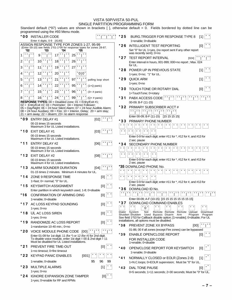
VISTA 50P/VISTA 50-PULSINGLE PARTITION PROGRAMMING FORM
Standard default (*97) values are shown in brackets [ ], otherwise default = 0. Fields bordered by dotted line can beprogrammed using the #93 Menu mode.* 0 0 INSTALLER CODE | | |
Enter 4 digits, 0-9 [4140]
ASSIGN RESPONSE TYPE FOR ZONES 1-27, 95-99 (Enter 00-10) see fields 1*01-1*09 for response types for zones 28-87.
*02 *03 *04 *05
1 | 9 | 17 | 25 |
2 | 10 | 18 | 26 |
3 | 11 | 19 | 27 |
4 | 12 | 20 | 0 |0
5 | 13 | 21 | 97 | polling loop short
6 | 14 | 22 | 95 | (1+Q panic)
7 | 15 | 23 | 96 | (3+ # panic)
8 | 16 | 24 | 99 | (Q+ # panic)
RESPONSE TYPES: 00 = Disabled zone; 01 = Entry/Exit #1;02 = Entry/Exit #2; 03 = Perimeter; 04 = Interior Follower;05 = Day/Night; 06 = 24 hour Silent Alarm; 07 = 24 hour Audible Alarm;08 = 24 hour Auxiliary; 09 = Fire; 10 = Interior, Delay; 20 = arm stay;21 = arm away; 22 = disarm; 23= no alarm response
* 0 9 ENTRY DELAY #1 [02] | 00-15 times 15 secondsMaximum 3 for UL Listed installations.
* 1 0 EXIT DELAY #1 [03] | 00-15 times 15 secondsMaximum 4 for UL Listed installations.
* 1 1 ENTRY DELAY #2 [06] | 00-15 times 15 secondsMaximum 3 for UL Listed installations.
* 1 2 EXIT DELAY #2 [08] | 00-15 times 15 secondsMaximum 4 for UL Listed installations.
* 1 3 ALARM SOUNDER DURATION [04] | 01-15 times 2 minutes. Minimum 4 minutes for UL.
* 1 4 ZONE 9 RESPONSE TIME [0] 1=fast; 0= normal; "0" for UL.
* 1 5 KEYSWITCH ASSIGNMENT [0] Enter partition in which keyswitch used, 1-8; 0=disable
*16 CONFIRMATION OF ARMING DING [0] 1=enable; 0=disable
* 1 7 AC LOSS KEYPAD SOUNDING [0] 1=yes; 0=no
* 1 8 UL AC LOSS SIREN [0] 1=yes; 0=no
* 1 9 RANDOMIZE AC LOSS REPORT [0] 1=randomize 10-40 min.; 0=no
* 2 0 VOICE MODULE PHONE CODE [00] | | Enter 01-09 for 1st digit; 11 (for *) or 12 (for #) for 2nd digit.To disable voice module, enter 1st digit = 00 & 2nd digit = 11Must be disabled for UL Listed installations.
* 2 1 PREVENT FIRE TIME-OUT [0] 1=no timeout; 0=fire timeout
* 2 2 KEYPAD PANIC ENABLES [001]
1=enable; 0=disable 95 96 99
* 2 3 MULTIPLE ALARMS [1] 1=yes; 0=no
* 2 4 IGNORE EXPANSION ZONE TAMPER [0] 1=yes; 0=enable for RF and RPMs
* 2 5 BURG.TRIGGER FOR RESPONSE TYPE 8 [1] 1=enable; 0=disable
* 2 6 INTELLIGENT TEST REPORTING [0] Set "0" for UL 1=yes, (no report sent if any other report
was recently sent); 0=no
* 2 7 TEST REPORT INTERVAL [024] | | Enter interval in hours, 001-999; 000=no report ; Max. 024 for UL.
* 2 8 POWER UP IN PREVIOUS STATE [1] 1=yes; 0=no; "1" for UL.
* 2 9 QUICK ARM [1] 1=yes; 0=no
* 3 0 TOUCH-TONE OR ROTARY DIAL [0] 1=TouchTone; 0=rotary
* 3 1 PABX ACCESS CODE | | | | 00-09; B-F (11-15)
* 3 2 PRIMARY SUBSCRIBER ACCT # | | | |
Enter 00-09; B-F (11-15) [15 15 15 15]
* 3 3 PRIMARY PHONE NUMBER
Enter 0-9 for each digit; enter #11 for *, #12 for #, and #13 for2 sec. pause
* 3 4 SECONDARY PHONE NUMBER
Enter 0-9 for each digit; enter #11 for *, #12 for #, and #13 for2 sec. pause
*35 DOWNLOAD PHONE No.
Enter 0-9 for each digit; enter #11 for *, #12 for #, and #13 for
2 sec. pause* 3 6 DOWNLOAD ID No. | | | | | | | | Enter 00-09; A-F (10-15) [15 15 15 15 15 15 15 15]* 3 7 DOWNLOAD COMMAND ENABLES 0
Dialer System Not Remote Remote Remote Upload DownloadShutdwn Shutdwn Used Bypass Disarm Arm Program ProgramSee field 1*53 for Callback disable option; [1=enable]; 0=disable; For ULinstallations, all options must be disabled.
* 3 8 PREVENT ZONE XX BYPASS [00] | 01-86; 00 if all zones (except Fire zones) can be bypassed
* 3 9 ENABLE OPEN/CLOSE REPORT [0] FOR INSTALLER CODE1=enable; 0=disable
* 4 0 OPEN/CLOSE REPORT FOR KEYSWITCH [0]
1=enable; 0=disable
* 4 1 NORMALLY CLOSED or EOLR (Zones 2-8) [1]
1=N.C.loops; 0=EOLR supervision; Must be "0" for UL.
* 4 2 DIAL TONE PAUSE [0]
0=5 seconds; 1=11 seconds; 2=30 seconds; Must be "0" for UL.
Ð 8 Ð
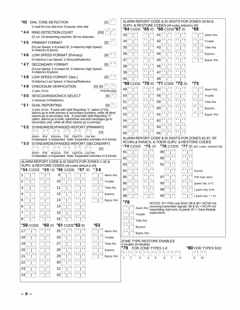
*43 DIAL TONE DETECTION [1]
1=wait for true dial tone; 0=pause, then dial
* 4 4 RING DETECTION COUNT [00] |
01-14; 15=answering machine; 00=no detection
* 4 5 PRIMARY FORMAT [0]
0=Low Speed; 1=Contact ID; 2=Ademco High Speed;3=Ademco Express
* 4 6 LOW SPEED FORMAT (Primary) [0] 0=Ademco Low Speed; 1=Sescoa/Radionics
* 4 7 SECONDARY FORMAT [0] 0=Low Speed; 1=Contact ID; 2=Ademco High Speed;3=Ademco Express
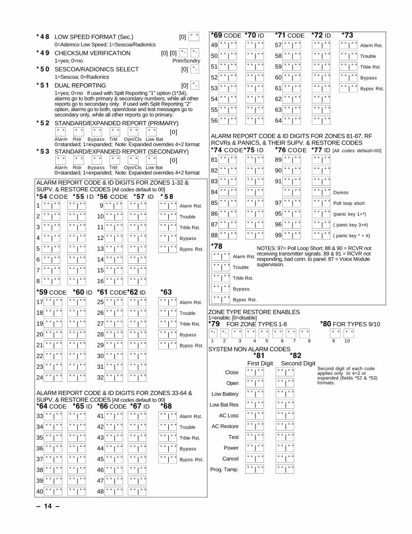
* 4 8 LOW SPEED FORMAT (Sec.) [0] 0=Ademco Low Speed; 1=Sescoa/Radionics
* 4 9 CHECKSUM VERIFICATION [0] [0]
1=yes; 0=no PrimScndry
* 5 0 SESCOA/RADIONICS SELECT [0]
1=Sescoa; 0=Radionics
* 5 1 DUAL REPORTING [0]
1=yes; 0=no If used with Spilt Reporting "1" option (1*34),alarms go to both primary & secondary numbers, while all otherreports go to secondary only. If used with Split Reporting "2"option, alarms go to both, open/close and test messages go tosecondary only, while all other reports go to primary.
* 5 2 STANDARD/EXPANDED REPORT (PRIMARY) [0]
Alarm Rstr Bypass Trbl Opn/Cls Low Bat0=standard; 1=expanded; Note: Expanded overrides 4+2 format
* 5 3 STANDARD/EXPANDED REPORT (SECONDARY) [0]
Alarm Rstr Bypass Trbl Opn/Cls Low Bat 0=standard; 1=expanded; Note: Expanded overrides 4+2 format
ALARM REPORT CODE & ID DIGITS FOR ZONES 1-32 &SUPV. & RESTORE CODES [All codes default to 00]*54 CODE *55 I D *56 CODE *57 ID * 5 81 | | 9 | | | Alarm Rst.
2 | | 10 | | | Trouble
3 | | 11 | | | Trble Rst.
4 | | 12 | | | Bypass
5 | | 13 | | | Bypss Rst.
6 | | 14 | |
7 | | 15 | |
8 | | 16 | |
*59 CODE *60 ID *61 CODE*62 ID *6317 | | 25 | | | Alarm Rst.
18 | | 26 | | | Trouble
19 | | 27 | | | Trble Rst.
20 | | 28 | | | Bypass
21 | | 29 | | | Bypss Rst.
22 | | 30 | |
23 | | 31 | |
24 | | 32 | |
ALARM REPORT CODE & ID DIGITS FOR ZONES 33-64 &SUPV. & RESTORE CODES [All codes default to 00]*64 CODE *65 ID *66 CODE*67 ID *6833 | | 41 | | | Alarm Rst.
34 | | 42 | | | Trouble
35 | | 43 | | | Trble Rst.
36 | | 44 | | | Bypass
37 | | 45 | | | Bypss Rst.
38 | | 46 | |
39 | | 47 | |
40 | | 48 | | *69 CODE *70 ID *71 CODE *72 ID *7349 | | 57 | | | Alarm Rst.
50 | | 58 | | | Trouble
51 | | 59 | | | Trble Rst.
52 | | 60 | | | Bypass
53 | | 61 | | | Bypss Rst.
54 | | 62 | |
55 | | 63 | |
56 | | 64 | | ALARM REPORT CODE & ID DIGITS FOR ZONES 81-87, RFRCVRs & PANICS, & THEIR SUPV. & RESTORE CODES*74 CODE *75 ID *76 CODE *77 ID [All codes default=00]
81 | | 89 | |
82 | | 90 | |
83 | | 91 | |
84 | | | | Duress
85 | | 97 | | Poll loop short
86 | | 95 | | (panic key 1+*)
87 | | 96 | | ( panic key 3+#)
88 | | 99 | | ( panic key * + #)
*78 | Alarm Rst.
| Trouble
| Trble Rst.
| Bypass
| Bypss Rst.
NOTES: 97= Poll Loop Short; 88 & 90 = RCVR notreceiving transmitter signals. 89 & 91 = RCVR notresponding, bad conn. to panel. 87 = Voice Modulesupervision.
ZONE TYPE RESTORE ENABLES1=enable; [0=disable]*79 FOR ZONE TYPES 1-8 *80 FOR TYPES 9/10
1 2 3 4 5 6 7 8 9 10
Ð 9 Ð
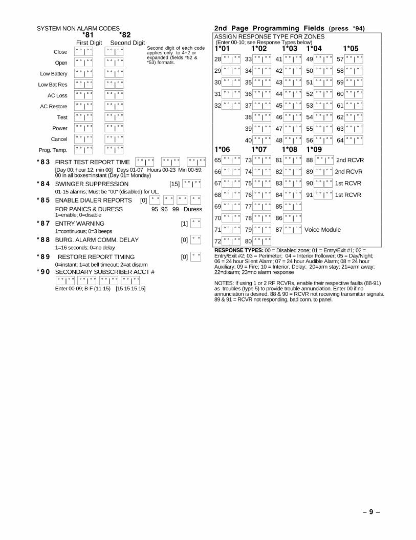
SYSTEM NON ALARM CODES*81 *82
First Digit Second DigitClose | |
Open | |
Low Battery | |
Low Bat Res | |
AC Loss | |
AC Restore | |
Test | |
Power | |
Cancel | |
Prog. Tamp. | |
Second digit of each codeapplies only to 4+2 orexpanded (fields *52 &*53) formats.
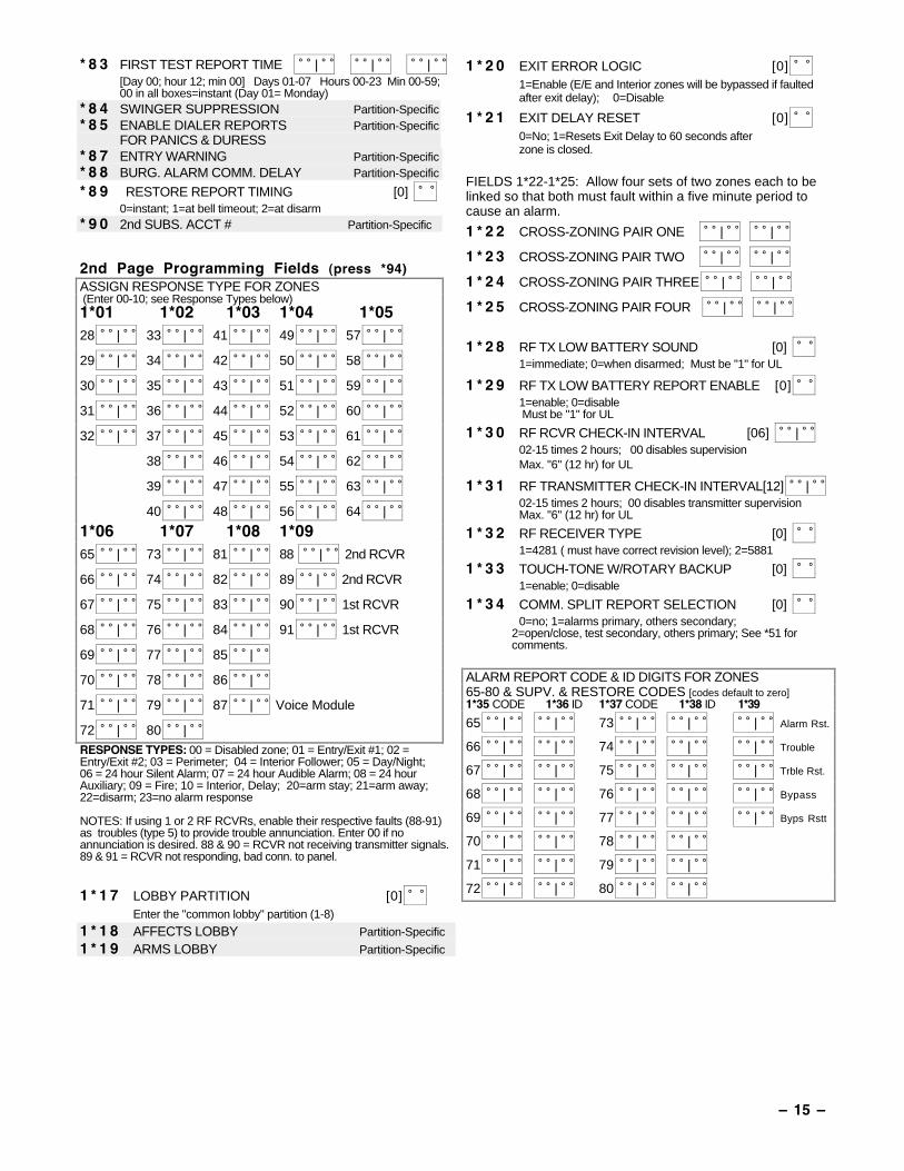
* 8 3 FIRST TEST REPORT TIME | | | [Day 00; hour 12; min 00] Days 01-07 Hours 00-23 Min 00-59;00 in all boxes=instant (Day 01= Monday)
* 8 4 SWINGER SUPPRESSION [15] | 01-15 alarms; Must be "00" (disabled) for UL.
* 8 5 ENABLE DIALER REPORTS [0] FOR PANICS & DURESS 95 96 99 Duress1=enable; 0=disable
* 8 7 ENTRY WARNING [1] 1=continuous; 0=3 beeps
* 8 8 BURG. ALARM COMM. DELAY [0] 1=16 seconds; 0=no delay
* 8 9 RESTORE REPORT TIMING [0] 0=instant; 1=at bell timeout; 2=at disarm
* 9 0 SECONDARY SUBSCRIBER ACCT # | | | |
Enter 00-09; B-F (11-15) [15 15 15 15]
2nd Page Programming Fields (press *94)ASSIGN RESPONSE TYPE FOR ZONES (Enter 00-10; see Response Types below)1*01 1*02 1*03 1*04 1*0528 | 33 | 41 | 49 | 57 |
29 | 34 | 42 | 50 | 58 |
30 | 35 | 43 | 51 | 59 |
31 | 36 | 44 | 52 | 60 |
32 | 37 | 45 | 53 | 61 |
38 | 46 | 54 | 62 |
39 | 47 | 55 | 63 |
40 | 48 | 56 | 64 |
1*06 1*07 1*08 1*0965 | 73 | 81 | 88 | 2nd RCVR
66 | 74 | 82 | 89 | 2nd RCVR
67 | 75 | 83 | 90 | 1st RCVR
68 | 76 | 84 | 91 | 1st RCVR
69 | 77 | 85 |
70 | 78 | 86 |
71 | 79 | 87 | Voice Module
72 | 80 | RESPONSE TYPES: 00 = Disabled zone; 01 = Entry/Exit #1; 02 =Entry/Exit #2; 03 = Perimeter; 04 = Interior Follower; 05 = Day/Night;06 = 24 hour Silent Alarm; 07 = 24 hour Audible Alarm; 08 = 24 hourAuxiliary; 09 = Fire; 10 = Interior, Delay; 20=arm stay; 21=arm away;22=disarm; 23=no alarm response
NOTES: If using 1 or 2 RF RCVRs, enable their respective faults (88-91)as troubles (type 5) to provide trouble annunciation. Enter 00 if noannunciation is desired. 88 & 90 = RCVR not receiving transmitter signals.89 & 91 = RCVR not responding, bad conn. to panel.
Ð 10 Ð
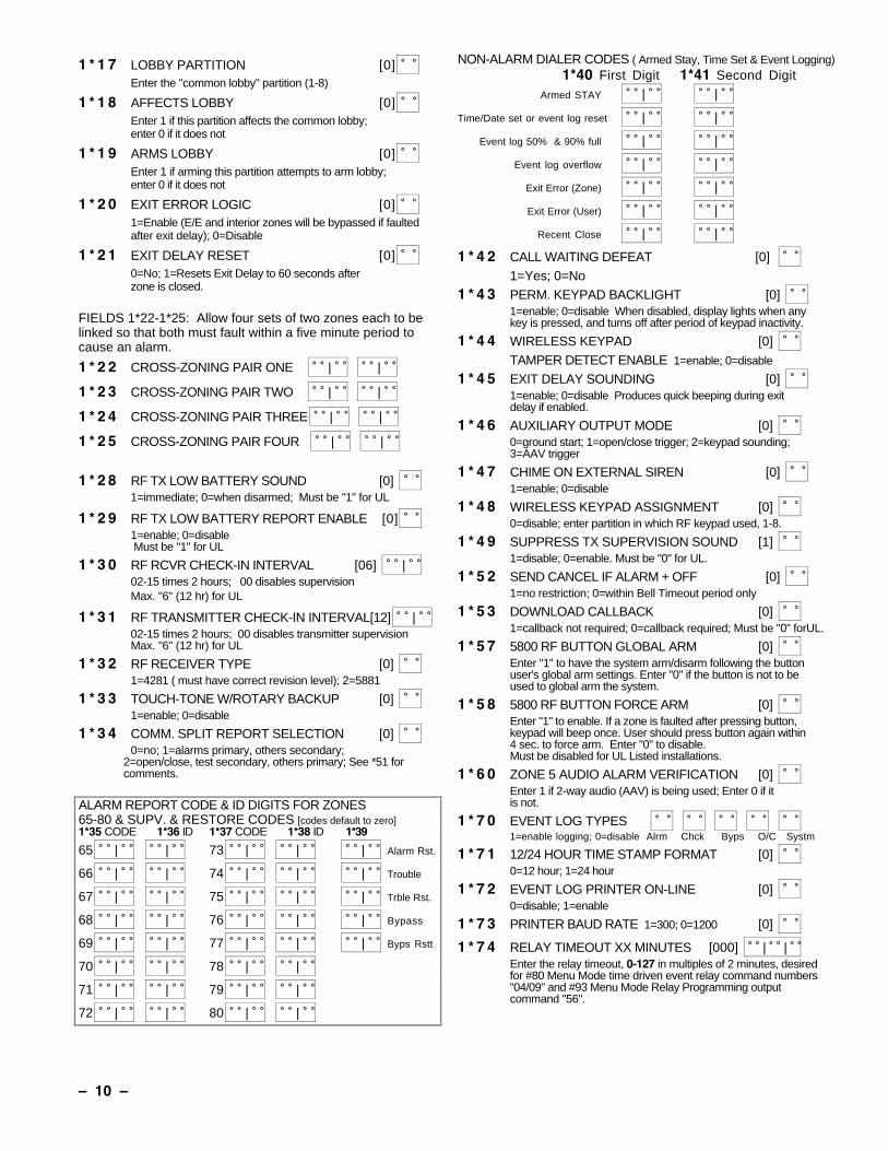
1 * 1 7 LOBBY PARTITION [0] Enter the "common lobby" partition (1-8)
1 * 1 8 AFFECTS LOBBY [0] Enter 1 if this partition affects the common lobby;enter 0 if it does not
1 * 1 9 ARMS LOBBY [0] Enter 1 if arming this partition attempts to arm lobby;enter 0 if it does not
1 * 2 0 EXIT ERROR LOGIC [0] 1=Enable (E/E and interior zones will be bypassed if faultedafter exit delay); 0=Disable
1 * 2 1 EXIT DELAY RESET [0] 0=No; 1=Resets Exit Delay to 60 seconds afterzone is closed.
FIELDS 1*22-1*25: Allow four sets of two zones each to belinked so that both must fault within a five minute period tocause an alarm.
1 * 2 2 CROSS-ZONING PAIR ONE | |
1 * 2 3 CROSS-ZONING PAIR TWO | |
1 * 2 4 CROSS-ZONING PAIR THREE | |
1 * 2 5 CROSS-ZONING PAIR FOUR | |
1 * 2 8 RF TX LOW BATTERY SOUND [0] 1=immediate; 0=when disarmed; Must be "1" for UL
1 * 2 9 RF TX LOW BATTERY REPORT ENABLE [0] 1=enable; 0=disable Must be "1" for UL
1 * 3 0 RF RCVR CHECK-IN INTERVAL [06] | 02-15 times 2 hours; 00 disables supervisionMax. "6" (12 hr) for UL
1 * 3 1 RF TRANSMITTER CHECK-IN INTERVAL[12] | 02-15 times 2 hours; 00 disables transmitter supervisionMax. "6" (12 hr) for UL
1 * 3 2 RF RECEIVER TYPE [0] 1=4281 ( must have correct revision level); 2=5881
1 * 3 3 TOUCH-TONE W/ROTARY BACKUP [0] 1=enable; 0=disable
1 * 3 4 COMM. SPLIT REPORT SELECTION [0] 0=no; 1=alarms primary, others secondary;
2=open/close, test secondary, others primary; See *51 forcomments.
ALARM REPORT CODE & ID DIGITS FOR ZONES65-80 & SUPV. & RESTORE CODES [codes default to zero]1*35 CODE 1*36 ID 1*37 CODE 1*38 ID 1*39
65 | | 73 | | | Alarm Rst.
66 | | 74 | | | Trouble
67 | | 75 | | | Trble Rst.
68 | | 76 | | | Bypass
69 | | 77 | | | Byps Rstt
70 | | 78 | |
71 | | 79 | |
72 | | 80 | |
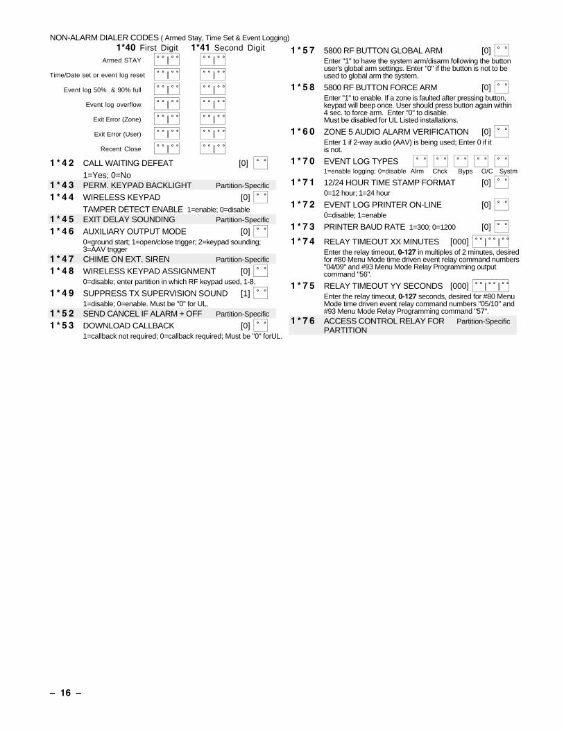
NON-ALARM DIALER CODES ( Armed Stay, Time Set & Event Logging)1*40 First Digit 1*41 Second Digit
Armed STAY | |
Time/Date set or event log reset | |
Event log 50% & 90% full | |
Event log overflow | |
Exit Error (Zone) | |
Exit Error (User) | |
Recent Close | |
1 * 4 2 CALL WAITING DEFEAT [0] 1=Yes; 0=No
1 * 4 3 PERM. KEYPAD BACKLIGHT [0] 1=enable; 0=disable When disabled, display lights when anykey is pressed, and turns off after period of keypad inactivity.
1 * 4 4 WIRELESS KEYPAD [0] TAMPER DETECT ENABLE 1=enable; 0=disable
1 * 4 5 EXIT DELAY SOUNDING [0] 1=enable; 0=disable Produces quick beeping during exitdelay if enabled.
1 * 4 6 AUXILIARY OUTPUT MODE [0] 0=ground start; 1=open/close trigger; 2=keypad sounding; 3=AAV trigger
1 * 4 7 CHIME ON EXTERNAL SIREN [0] 1=enable; 0=disable
1 * 4 8 WIRELESS KEYPAD ASSIGNMENT [0] 0=disable; enter partition in which RF keypad used, 1-8.
1 * 4 9 SUPPRESS TX SUPERVISION SOUND [1] 1=disable; 0=enable. Must be "0" for UL.
1 * 5 2 SEND CANCEL IF ALARM + OFF [0] 1=no restriction; 0=within Bell Timeout period only
1 * 5 3 DOWNLOAD CALLBACK [0] 1=callback not required; 0=callback required; Must be "0" forUL.
1 * 5 7 5800 RF BUTTON GLOBAL ARM [0] Enter "1" to have the system arm/disarm following the buttonuser's global arm settings. Enter "0" if the button is not to beused to global arm the system.
1 * 5 8 5800 RF BUTTON FORCE ARM [0] Enter "1" to enable. If a zone is faulted after pressing button,keypad will beep once. User should press button again within4 sec. to force arm. Enter "0" to disable.Must be disabled for UL Listed installations.
1 * 6 0 ZONE 5 AUDIO ALARM VERIFICATION [0] Enter 1 if 2-way audio (AAV) is being used; Enter 0 if it is not.
1 * 7 0 EVENT LOG TYPES 1=enable logging; 0=disable Alrm Chck Byps O/C Systm
1 * 7 1 12/24 HOUR TIME STAMP FORMAT [0] 0=12 hour; 1=24 hour
1 * 7 2 EVENT LOG PRINTER ON-LINE [0] 0=disable; 1=enable
1 * 7 3 PRINTER BAUD RATE 1=300; 0=1200 [0]
1 * 7 4 RELAY TIMEOUT XX MINUTES [000] | | Enter the relay timeout, 0-127 in multiples of 2 minutes, desiredfor #80 Menu Mode time driven event relay command numbers"04/09" and #93 Menu Mode Relay Programming outputcommand "56".
Ð 11 Ð
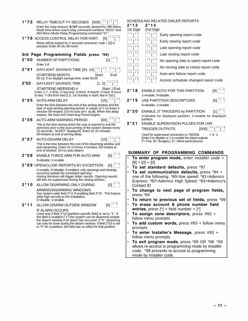
1 * 7 5 RELAY TIMEOUT YY SECONDS [000] | | Enter the relay timeout, 0-127 seconds, desired for #80 MenuMode time driven event relay command numbers "05/10" and#93 Menu Mode Relay Programming command "57".
1 * 7 6 ACCESS CONTROL RELAY FOR PART. [0] | Relay will be pulsed for 2 seconds whenever code + [0] ispressed. Enter 00-16; 00=none
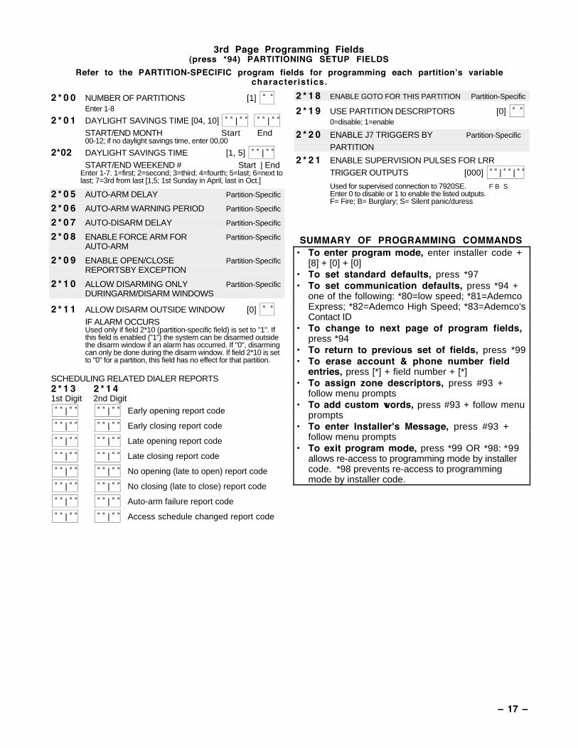
3rd Page Programming Fields press *94)2 * 0 0 NUMBER OF PARTITIONS [1]
Enter 1-8
2 * 0 1 DAYLIGHT SAVINGS TIME [04, 10] | | START/END MONTH Start End00-12; if no daylight savings time, enter 00,00
2*02 DAYLIGHT SAVINGS TIME [1, 5] | START/END WEEKEND # Start | End
Enter 1-7. 1=first; 2=second; 3=third; 4=fourth; 5=last; 6=nextto last; 7=3rd from last [1,5; 1st Sunday in April, last in Oct.]
2 * 0 5 AUTO-ARM DELAY [15] | Enter the time between the end of the arming window and thestart of auto-arming warning period, in values of 1-14 times 4minutes 00=instant; [15=no auto arm at all]. When this delayexpires, the Auto-Arm Warrning Period begins.
2 * 0 6 AUTO-ARM WARNING PERIOD [00] | This is the time during which the user is warned to exit thepremises prior to the auto-arming of the system (beeps every15 seconds; "ALERT" displayed). Enter 01-15 minutes.00=instant at end of arming delay .
2 * 0 7 AUTO-DISARM DELAY [15] | This is the time between the end of the disarming window andauto-disarming. Enter 01-14 times 4 minutes; 00=instant atend of window; 15=no auto-disarm.
2 * 0 8 ENABLE FORCE ARM FOR AUTO-ARM [0] 0=disable; 1=enable
2 * 0 9 OPEN/CLOSE REPORTS BY EXCEPTION [0] 1=enable; 0=disable; If enabled, only openings and closingsoccurring outside the scheduled opening /closing windows will trigger dialer reports. Opening reportswill also be suppressed during the closing window.,
2 * 1 0 ALLOW DISARMING ONLY DURING [0] ARMING/DISARMING WINDOWSSee system-wide field 2*11 if enabling field 2*10. This featureadds high security to the installation.0=disable; 1=enable
2 * 1 1 ALLOW DISARM OUTSIDE WINDOW [0] IF ALARM OCCURSUsed only if field 2*10 (partition-specific field) is set to "1". Ifthis field is enabled ("1") the system can be disarmed outsidethe disarm window if an alarm has occurred. If "0", disarmingcan only be done during the disarm window. If field 2*10 is setto "0" for a partition, this field has no effect for that partition.
SCHEDULING RELATED DIALER REPORTS2 * 1 3 2 * 1 41st Digit 2nd Digit | | Early opening report code
| | Early closing report code
| | Late opening report code
| | Late closing report code
| | No opening (late to open) report code
| | No closing (late to close) report code
| | Auto-arm failure report code
| | Access schedule changed report code
2 * 1 8 ENABLE GOTO FOR THIS PARTITION [0] 1=enable; 0=disable
2 * 1 9 USE PARTITION DESCRIPTORS [0] 0=disable; 1=enable
2 * 2 0 ENABLE J7 TRIGGERS by PARTITION [1] 0=disable for displayed partition; 1=enable for displayed
partition2 * 2 1 ENABLE SUPERVISION PULSES FOR LRR
TRIGGER OUTPUTS [000] | |
Used for supervised connection to 7920SE. F B SEnter 0 to disable or 1 to enable the listed outputs.F= Fire; B= Burglary; S= Silent panic/duress
SUMMARY OF PROGRAMMING COMMANDS¥ To enter program mode, enter installer code +
[8] + [0] + [0]¥ To set standard defaults, press *97¥ To set communication defaults, press *94 +
one of the following: *80=low speed; *81=AdemcoExpress; *82=Ademco High Speed; *83=Ademco'sContact ID
¥ To change to next page of program fields,press *94
¥ To return to previous set of fields, press *99¥ To erase account & phone number field
entries, press [*] + field number + [*]¥ To assign zone descriptors, press #93 +
follow menu prompts¥ To add custom words, press #93 + follow menu
prompts¥ To enter Installer's Message, press #93 +
follow menu prompts¥ To exit program mode, press *99 OR *98: *99
allows re-access to programming mode by installercode. *98 prevents re-access to programmingmode by installer code.

Ð 12 Ð
NOTES:
Ð 13 Ð
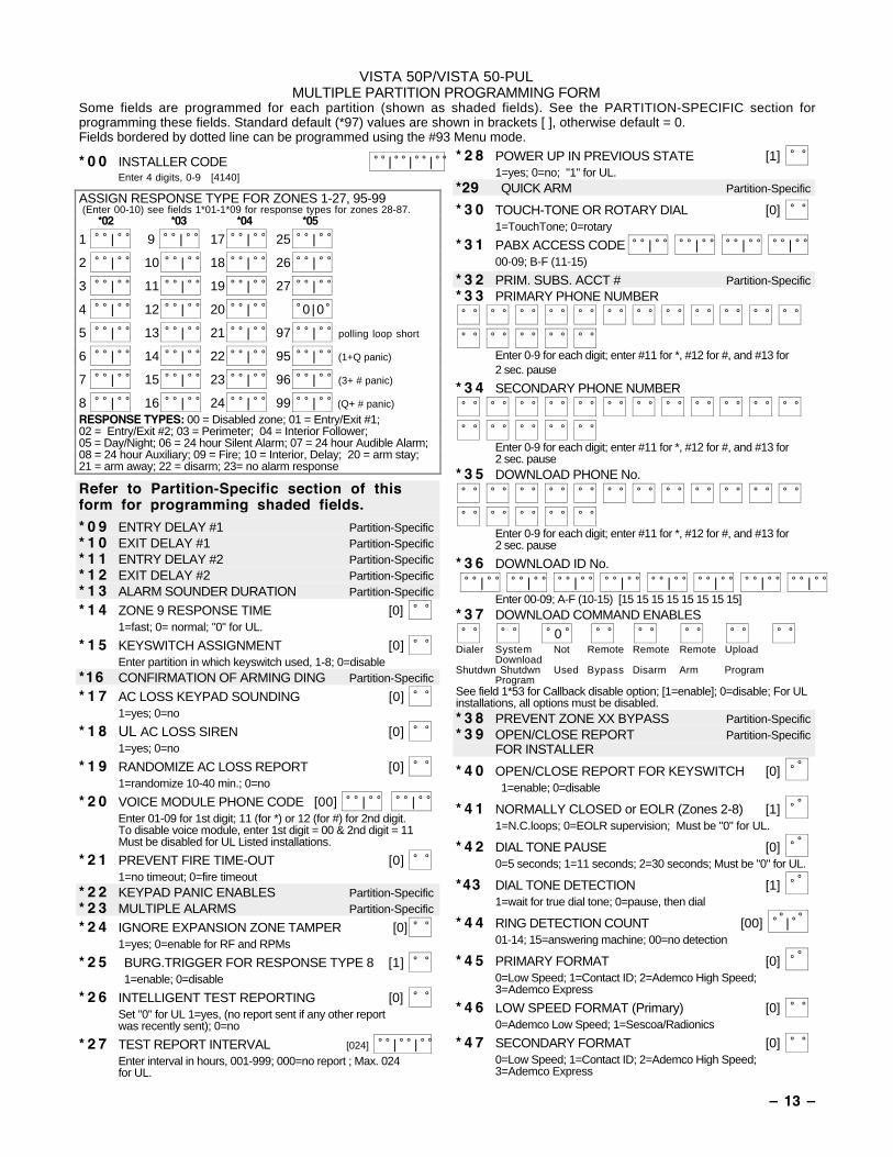
VISTA 50P/VISTA 50-PULMULTIPLE PARTITION PROGRAMMING FORM
Some fields are programmed for each partition (shown as shaded fields). See the PARTITION-SPECIFIC section forprogramming these fields. Standard default (*97) values are shown in brackets [ ], otherwise default = 0.Fields bordered by dotted line can be programmed using the #93 Menu mode.
* 0 0 INSTALLER CODE | | | Enter 4 digits, 0-9 [4140]
ASSIGN RESPONSE TYPE FOR ZONES 1-27, 95-99 (Enter 00-10) see fields 1*01-1*09 for response types for zones 28-87.
*02 *03 *04 *05
1 | 9 | 17 | 25 |
2 | 10 | 18 | 26 |
3 | 11 | 19 | 27 |
4 | 12 | 20 | 0 |0
5 | 13 | 21 | 97 | polling loop short
6 | 14 | 22 | 95 | (1+Q panic)
7 | 15 | 23 | 96 | (3+ # panic)
8 | 16 | 24 | 99 | (Q+ # panic)
RESPONSE TYPES: 00 = Disabled zone; 01 = Entry/Exit #1;02 = Entry/Exit #2; 03 = Perimeter; 04 = Interior Follower;05 = Day/Night; 06 = 24 hour Silent Alarm; 07 = 24 hour Audible Alarm;08 = 24 hour Auxiliary; 09 = Fire; 10 = Interior, Delay; 20 = arm stay;21 = arm away; 22 = disarm; 23= no alarm response
Refer to Partition-Specific section of thisform for programming shaded fields.
* 0 9 ENTRY DELAY #1 Partition-Specific* 1 0 EXIT DELAY #1 Partition-Specific* 1 1 ENTRY DELAY #2 Partition-Specific* 1 2 EXIT DELAY #2 Partition-Specific* 1 3 ALARM SOUNDER DURATION Partition-Specific
* 1 4 ZONE 9 RESPONSE TIME [0] 1=fast; 0= normal; "0" for UL.
* 1 5 KEYSWITCH ASSIGNMENT [0] Enter partition in which keyswitch used, 1-8; 0=disable
*16 CONFIRMATION OF ARMING DING Partition-Specific
* 1 7 AC LOSS KEYPAD SOUNDING [0] 1=yes; 0=no
* 1 8 UL AC LOSS SIREN [0] 1=yes; 0=no
* 1 9 RANDOMIZE AC LOSS REPORT [0] 1=randomize 10-40 min.; 0=no
* 2 0 VOICE MODULE PHONE CODE [00] | | Enter 01-09 for 1st digit; 11 (for *) or 12 (for #) for 2nd digit.To disable voice module, enter 1st digit = 00 & 2nd digit = 11Must be disabled for UL Listed installations.
* 2 1 PREVENT FIRE TIME-OUT [0] 1=no timeout; 0=fire timeout
* 2 2 KEYPAD PANIC ENABLES Partition-Specific* 2 3 MULTIPLE ALARMS Partition-Specific
* 2 4 IGNORE EXPANSION ZONE TAMPER [0] 1=yes; 0=enable for RF and RPMs
* 2 5 BURG.TRIGGER FOR RESPONSE TYPE 8 [1] 1=enable; 0=disable
* 2 6 INTELLIGENT TEST REPORTING [0] Set "0" for UL 1=yes, (no report sent if any other report
was recently sent); 0=no
* 2 7 TEST REPORT INTERVAL [024] | | Enter interval in hours, 001-999; 000=no report ; Max. 024 for UL.
* 2 8 POWER UP IN PREVIOUS STATE [1] 1=yes; 0=no; "1" for UL.
*29 QUICK ARM Partition-Specific
* 3 0 TOUCH-TONE OR ROTARY DIAL [0] 1=TouchTone; 0=rotary
* 3 1 PABX ACCESS CODE | | | | 00-09; B-F (11-15)
* 3 2 PRIM. SUBS. ACCT # Partition-Specific* 3 3 PRIMARY PHONE NUMBER
Enter 0-9 for each digit; enter #11 for *, #12 for #, and #13 for2 sec. pause
* 3 4 SECONDARY PHONE NUMBER
Enter 0-9 for each digit; enter #11 for *, #12 for #, and #13 for2 sec. pause
* 3 5 DOWNLOAD PHONE No.
Enter 0-9 for each digit; enter #11 for *, #12 for #, and #13 for2 sec. pause
* 3 6 DOWNLOAD ID No. | | | | | | | | Enter 00-09; A-F (10-15) [15 15 15 15 15 15 15 15]* 3 7 DOWNLOAD COMMAND ENABLES 0
Dialer System Not Remote Remote Remote UploadDownload
Shutdwn Shutdwn Used Bypass Disarm Arm ProgramProgram
See field 1*53 for Callback disable option; [1=enable]; 0=disable; For ULinstallations, all options must be disabled.* 3 8 PREVENT ZONE XX BYPASS Partition-Specific* 3 9 OPEN/CLOSE REPORT Partition-Specific
FOR INSTALLER
* 4 0 OPEN/CLOSE REPORT FOR KEYSWITCH [0]
1=enable; 0=disable
* 4 1 NORMALLY CLOSED or EOLR (Zones 2-8) [1]
1=N.C.loops; 0=EOLR supervision; Must be "0" for UL.
* 4 2 DIAL TONE PAUSE [0]
0=5 seconds; 1=11 seconds; 2=30 seconds; Must be "0" for UL.
*43 DIAL TONE DETECTION [1]
1=wait for true dial tone; 0=pause, then dial
* 4 4 RING DETECTION COUNT [00] |
01-14; 15=answering machine; 00=no detection
* 4 5 PRIMARY FORMAT [0]
0=Low Speed; 1=Contact ID; 2=Ademco High Speed;3=Ademco Express
* 4 6 LOW SPEED FORMAT (Primary) [0] 0=Ademco Low Speed; 1=Sescoa/Radionics
* 4 7 SECONDARY FORMAT [0] 0=Low Speed; 1=Contact ID; 2=Ademco High Speed;3=Ademco Express
Ð 14 Ð
* 4 8 LOW SPEED FORMAT (Sec.) [0] 0=Ademco Low Speed; 1=Sescoa/Radionics
* 4 9 CHECKSUM VERIFICATION [0] [0]
1=yes; 0=no PrimScndry
* 5 0 SESCOA/RADIONICS SELECT [0]
1=Sescoa; 0=Radionics
* 5 1 DUAL REPORTING [0]
1=yes; 0=no If used with Spilt Reporting "1" option (1*34),alarms go to both primary & secondary numbers, while all otherreports go to secondary only. If used with Split Reporting "2"option, alarms go to both, open/close and test messages go tosecondary only, while all other reports go to primary.
* 5 2 STANDARD/EXPANDED REPORT (PRIMARY) [0]
Alarm Rstr Bypass Trbl Opn/Cls Low Bat0=standard; 1=expanded; Note: Expanded overrides 4+2 format
* 5 3 STANDARD/EXPANDED REPORT (SECONDARY) [0]
Alarm Rstr Bypass Trbl Opn/Cls Low Bat 0=standard; 1=expanded; Note: Expanded overrides 4+2 format
ALARM REPORT CODE & ID DIGITS FOR ZONES 1-32 &SUPV. & RESTORE CODES [All codes default to 00]*54 CODE *55 I D *56 CODE *57 ID * 5 81 | | 9 | | | Alarm Rst.
2 | | 10 | | | Trouble
3 | | 11 | | | Trble Rst.
4 | | 12 | | | Bypass
5 | | 13 | | | Bypss Rst.
6 | | 14 | |
7 | | 15 | |
8 | | 16 | |
*59 CODE *60 ID *61 CODE*62 ID *6317 | | 25 | | | Alarm Rst.
18 | | 26 | | | Trouble
19 | | 27 | | | Trble Rst.
20 | | 28 | | | Bypass
21 | | 29 | | | Bypss Rst.
22 | | 30 | |
23 | | 31 | |
24 | | 32 | |
ALARM REPORT CODE & ID DIGITS FOR ZONES 33-64 &SUPV. & RESTORE CODES [All codes default to 00]*64 CODE *65 ID *66 CODE *67 ID *6833 | | 41 | | | Alarm Rst.
34 | | 42 | | | Trouble
35 | | 43 | | | Trble Rst.
36 | | 44 | | | Bypass
37 | | 45 | | | Bypss Rst.
38 | | 46 | |
39 | | 47 | |
40 | | 48 | |
*69 CODE *70 ID *71 CODE *72 ID *7349 | | 57 | | | Alarm Rst.
50 | | 58 | | | Trouble
51 | | 59 | | | Trble Rst.
52 | | 60 | | | Bypass
53 | | 61 | | | Bypss Rst.
54 | | 62 | |
55 | | 63 | |
56 | | 64 | |
ALARM REPORT CODE & ID DIGITS FOR ZONES 81-87, RFRCVRs & PANICS, & THEIR SUPV. & RESTORE CODES*74 CODE*75 ID *76 CODE *77 ID [All codes default=00]
81 | | 89 | |
82 | | 90 | |
83 | | 91 | |
84 | | | | Duress
85 | | 97 | | Poll loop short
86 | | 95 | | (panic key 1+*)
87 | | 96 | | ( panic key 3+#)
88 | | 99 | | ( panic key * + #)
*78 | Alarm Rst.
| Trouble
| Trble Rst.
| Bypass
| Bypss Rst.
NOTES: 97= Poll Loop Short; 88 & 90 = RCVR notreceiving transmitter signals. 89 & 91 = RCVR notresponding, bad conn. to panel. 87 = Voice Modulesupervision.
ZONE TYPE RESTORE ENABLES1=enable; [0=disable]*79 FOR ZONE TYPES 1-8 *80 FOR TYPES 9/10
1 2 3 4 5 6 7 8 9 10
SYSTEM NON ALARM CODES*81 *82
First Digit Second DigitClose | |
Open | |
Low Battery | |
Low Bat Res | |
AC Loss | |
AC Restore | |
Test | |
Power | |
Cancel | |
Prog. Tamp. | |
Second digit of each codeapplies only to 4+2 orexpanded (fields *52 & *53)formats.
Ð 15 Ð
* 8 3 FIRST TEST REPORT TIME | | | [Day 00; hour 12; min 00] Days 01-07 Hours 00-23 Min 00-59;00 in all boxes=instant (Day 01= Monday)
* 8 4 SWINGER SUPPRESSION Partition-Specific* 8 5 ENABLE DIALER REPORTS Partition-Specific
FOR PANICS & DURESS* 8 7 ENTRY WARNING Partition-Specific* 8 8 BURG. ALARM COMM. DELAY Partition-Specific
* 8 9 RESTORE REPORT TIMING [0] 0=instant; 1=at bell timeout; 2=at disarm
* 9 0 2nd SUBS. ACCT # Partition-Specific
2nd Page Programming Fields (press *94)ASSIGN RESPONSE TYPE FOR ZONES (Enter 00-10; see Response Types below)1*01 1*02 1*03 1*04 1*0528 | 33 | 41 | 49 | 57 |
29 | 34 | 42 | 50 | 58 |
30 | 35 | 43 | 51 | 59 |
31 | 36 | 44 | 52 | 60 |
32 | 37 | 45 | 53 | 61 |
38 | 46 | 54 | 62 |
39 | 47 | 55 | 63 |
40 | 48 | 56 | 64 |
1*06 1*07 1*08 1*0965 | 73 | 81 | 88 | 2nd RCVR
66 | 74 | 82 | 89 | 2nd RCVR
67 | 75 | 83 | 90 | 1st RCVR
68 | 76 | 84 | 91 | 1st RCVR
69 | 77 | 85 |
70 | 78 | 86 |
71 | 79 | 87 | Voice Module
72 | 80 | RESPONSE TYPES: 00 = Disabled zone; 01 = Entry/Exit #1; 02 =Entry/Exit #2; 03 = Perimeter; 04 = Interior Follower; 05 = Day/Night;06 = 24 hour Silent Alarm; 07 = 24 hour Audible Alarm; 08 = 24 hourAuxiliary; 09 = Fire; 10 = Interior, Delay; 20=arm stay; 21=arm away;22=disarm; 23=no alarm response
NOTES: If using 1 or 2 RF RCVRs, enable their respective faults (88-91)as troubles (type 5) to provide trouble annunciation. Enter 00 if noannunciation is desired. 88 & 90 = RCVR not receiving transmitter signals.89 & 91 = RCVR not responding, bad conn. to panel.
1 * 1 7 LOBBY PARTITION [0] Enter the "common lobby" partition (1-8)
1 * 1 8 AFFECTS LOBBY Partition-Specific
1 * 1 9 ARMS LOBBY Partition-Specific
1 * 2 0 EXIT ERROR LOGIC [0] 1=Enable (E/E and Interior zones will be bypassed if faultedafter exit delay); 0=Disable
1 * 2 1 EXIT DELAY RESET [0] 0=No; 1=Resets Exit Delay to 60 seconds afterzone is closed.
FIELDS 1*22-1*25: Allow four sets of two zones each to belinked so that both must fault within a five minute period tocause an alarm.
1 * 2 2 CROSS-ZONING PAIR ONE | |
1 * 2 3 CROSS-ZONING PAIR TWO | |
1 * 2 4 CROSS-ZONING PAIR THREE | |
1 * 2 5 CROSS-ZONING PAIR FOUR | |
1 * 2 8 RF TX LOW BATTERY SOUND [0] 1=immediate; 0=when disarmed; Must be "1" for UL
1 * 2 9 RF TX LOW BATTERY REPORT ENABLE [0] 1=enable; 0=disable Must be "1" for UL
1 * 3 0 RF RCVR CHECK-IN INTERVAL [06] | 02-15 times 2 hours; 00 disables supervisionMax. "6" (12 hr) for UL
1 * 3 1 RF TRANSMITTER CHECK-IN INTERVAL[12] | 02-15 times 2 hours; 00 disables transmitter supervisionMax. "6" (12 hr) for UL
1 * 3 2 RF RECEIVER TYPE [0] 1=4281 ( must have correct revision level); 2=5881
1 * 3 3 TOUCH-TONE W/ROTARY BACKUP [0] 1=enable; 0=disable
1 * 3 4 COMM. SPLIT REPORT SELECTION [0] 0=no; 1=alarms primary, others secondary;
2=open/close, test secondary, others primary; See *51 forcomments.
ALARM REPORT CODE & ID DIGITS FOR ZONES65-80 & SUPV. & RESTORE CODES [codes default to zero]1*35 CODE 1*36 ID 1*37 CODE 1*38 ID 1*39
65 | | 73 | | | Alarm Rst.
66 | | 74 | | | Trouble
67 | | 75 | | | Trble Rst.
68 | | 76 | | | Bypass
69 | | 77 | | | Byps Rstt
70 | | 78 | |
71 | | 79 | |
72 | | 80 | |
Ð 16 Ð
NON-ALARM DIALER CODES ( Armed Stay, Time Set & Event Logging)1*40 First Digit 1*41 Second Digit
Armed STAY | |
Time/Date set or event log reset | |
Event log 50% & 90% full | |
Event log overflow | |
Exit Error (Zone) | |
Exit Error (User) | |
Recent Close | |
1 * 4 2 CALL WAITING DEFEAT [0] 1=Yes; 0=No
1 * 4 3 PERM. KEYPAD BACKLIGHT Partition-Specific
1 * 4 4 WIRELESS KEYPAD [0] TAMPER DETECT ENABLE 1=enable; 0=disable
1 * 4 5 EXIT DELAY SOUNDING Partition-Specific
1 * 4 6 AUXILIARY OUTPUT MODE [0] 0=ground start; 1=open/close trigger; 2=keypad sounding; 3=AAV trigger
1 * 4 7 CHIME ON EXT. SIREN Partition-Specific
1 * 4 8 WIRELESS KEYPAD ASSIGNMENT [0] 0=disable; enter partition in which RF keypad used, 1-8.
1 * 4 9 SUPPRESS TX SUPERVISION SOUND [1] 1=disable; 0=enable. Must be "0" for UL.
1 * 5 2 SEND CANCEL IF ALARM + OFF Partition-Specific
1 * 5 3 DOWNLOAD CALLBACK [0] 1=callback not required; 0=callback required; Must be "0" forUL.
1 * 5 7 5800 RF BUTTON GLOBAL ARM [0] Enter "1" to have the system arm/disarm following the buttonuser's global arm settings. Enter "0" if the button is not to beused to global arm the system.
1 * 5 8 5800 RF BUTTON FORCE ARM [0] Enter "1" to enable. If a zone is faulted after pressing button,keypad will beep once. User should press button again within4 sec. to force arm. Enter "0" to disable.Must be disabled for UL Listed installations.
1 * 6 0 ZONE 5 AUDIO ALARM VERIFICATION [0] Enter 1 if 2-way audio (AAV) is being used; Enter 0 if it is not.
1 * 7 0 EVENT LOG TYPES 1=enable logging; 0=disable Alrm Chck Byps O/C Systm
1 * 7 1 12/24 HOUR TIME STAMP FORMAT [0] 0=12 hour; 1=24 hour
1 * 7 2 EVENT LOG PRINTER ON-LINE [0] 0=disable; 1=enable
1 * 7 3 PRINTER BAUD RATE 1=300; 0=1200 [0]
1 * 7 4 RELAY TIMEOUT XX MINUTES [000] | | Enter the relay timeout, 0-127 in multiples of 2 minutes, desiredfor #80 Menu Mode time driven event relay command numbers"04/09" and #93 Menu Mode Relay Programming outputcommand "56".
1 * 7 5 RELAY TIMEOUT YY SECONDS [000] | | Enter the relay timeout, 0-127 seconds, desired for #80 MenuMode time driven event relay command numbers "05/10" and#93 Menu Mode Relay Programming command "57".
1 * 7 6 ACCESS CONTROL RELAY FOR Partition-SpecificPARTITION
Ð 17 Ð
3rd Page Programming Fields(press *94) PARTITIONING SETUP FIELDS
Refer to the PARTITION-SPECIFIC program fields for programming each partitionÕs variablecharacterist ics.
2 * 0 0 NUMBER OF PARTITIONS [1] Enter 1-8
2 * 0 1 DAYLIGHT SAVINGS TIME [04, 10] | | START/END MONTH Start End00-12; if no daylight savings time, enter 00,00
2*02 DAYLIGHT SAVINGS TIME [1, 5] | START/END WEEKEND # Start | End
Enter 1-7. 1=first; 2=second; 3=third; 4=fourth; 5=last; 6=next tolast; 7=3rd from last [1,5; 1st Sunday in April, last in Oct.]
2 * 0 5 AUTO-ARM DELAY Partition-Specific
2 * 0 6 AUTO-ARM WARNING PERIOD Partition-Specific
2 * 0 7 AUTO-DISARM DELAY Partition-Specific
2 * 0 8 ENABLE FORCE ARM FOR Partition-SpecificAUTO-ARM
2 * 0 9 ENABLE OPEN/CLOSE Partition-SpecificREPORTSBY EXCEPTION
2 * 1 0 ALLOW DISARMING ONLY Partition-SpecificDURINGARM/DISARM WINDOWS
2 * 1 1 ALLOW DISARM OUTSIDE WINDOW [0] IF ALARM OCCURSUsed only if field 2*10 (partition-specific field) is set to "1". Ifthis field is enabled ("1") the system can be disarmed outsidethe disarm window if an alarm has occurred. If "0", disarmingcan only be done during the disarm window. If field 2*10 is setto "0" for a partition, this field has no effect for that partition.
SCHEDULING RELATED DIALER REPORTS2 * 1 3 2 * 1 41st Digit 2nd Digit | | Early opening report code
| | Early closing report code
| | Late opening report code
| | Late closing report code
| | No opening (late to open) report code
| | No closing (late to close) report code
| | Auto-arm failure report code
| | Access schedule changed report code
2 * 1 8 ENABLE GOTO FOR THIS PARTITION Partition-Specific
2 * 1 9 USE PARTITION DESCRIPTORS [0] 0=disable; 1=enable
2 * 2 0 ENABLE J7 TRIGGERS BY Partition-Specific
PARTITION
2 * 2 1 ENABLE SUPERVISION PULSES FOR LRRTRIGGER OUTPUTS [000] | |
Used for supervised connection to 7920SE. F B SEnter 0 to disable or 1 to enable the listed outputs.F= Fire; B= Burglary; S= Silent panic/duress
SUMMARY OF PROGRAMMING COMMANDS¥ To enter program mode, enter installer code +
[8] + [0] + [0]¥ To set standard defaults, press *97¥ To set communication defaults, press *94 +
one of the following: *80=low speed; *81=AdemcoExpress; *82=Ademco High Speed; *83=Ademco'sContact ID
¥ To change to next page of program fields,press *94
¥ To return to previous set of fields, press *99¥ To erase account & phone number field
entries, press [*] + field number + [*]¥ To assign zone descriptors, press #93 +
follow menu prompts¥ To add custom words, press #93 + follow menu
prompts¥ To enter Installer's Message, press #93 +
follow menu prompts¥ To exit program mode, press *99 OR *98: *99
allows re-access to programming mode by installercode. *98 prevents re-access to programmingmode by installer code.
Ð 18 Ð
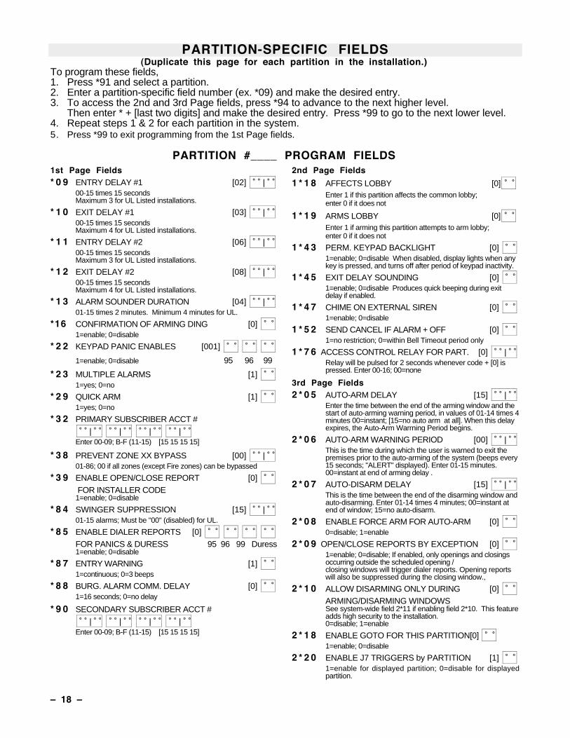
PARTITION-SPECIFIC FIELDS(Duplicate this page for each partition in the installation.)
To program these fields,1. Press *91 and select a partition.2. Enter a partition-specific field number (ex. *09) and make the desired entry.3. To access the 2nd and 3rd Page fields, press *94 to advance to the next higher level.
Then enter * + [last two digits] and make the desired entry. Press *99 to go to the next lower level.4. Repeat steps 1 & 2 for each partition in the system.5. Press *99 to exit programming from the 1st Page fields.
PARTITION #____ PROGRAM FIELDS1st Page Fields* 0 9 ENTRY DELAY #1 [02] |
00-15 times 15 secondsMaximum 3 for UL Listed installations.
* 1 0 EXIT DELAY #1 [03] | 00-15 times 15 secondsMaximum 4 for UL Listed installations.
* 1 1 ENTRY DELAY #2 [06] | 00-15 times 15 secondsMaximum 3 for UL Listed installations.
* 1 2 EXIT DELAY #2 [08] | 00-15 times 15 secondsMaximum 4 for UL Listed installations.
* 1 3 ALARM SOUNDER DURATION [04] | 01-15 times 2 minutes. Minimum 4 minutes for UL.
*16 CONFIRMATION OF ARMING DING [0] 1=enable; 0=disable
* 2 2 KEYPAD PANIC ENABLES [001]
1=enable; 0=disable 95 96 99
* 2 3 MULTIPLE ALARMS [1] 1=yes; 0=no
* 2 9 QUICK ARM [1] 1=yes; 0=no
* 3 2 PRIMARY SUBSCRIBER ACCT # | | | |
Enter 00-09; B-F (11-15) [15 15 15 15]
* 3 8 PREVENT ZONE XX BYPASS [00] | 01-86; 00 if all zones (except Fire zones) can be bypassed
* 3 9 ENABLE OPEN/CLOSE REPORT [0] FOR INSTALLER CODE1=enable; 0=disable
* 8 4 SWINGER SUPPRESSION [15] | 01-15 alarms; Must be "00" (disabled) for UL.
* 8 5 ENABLE DIALER REPORTS [0] FOR PANICS & DURESS 95 96 99 Duress1=enable; 0=disable
* 8 7 ENTRY WARNING [1] 1=continuous; 0=3 beeps
* 8 8 BURG. ALARM COMM. DELAY [0] 1=16 seconds; 0=no delay
* 9 0 SECONDARY SUBSCRIBER ACCT # | | | |
Enter 00-09; B-F (11-15) [15 15 15 15]
2nd Page Fields
1 * 1 8 AFFECTS LOBBY [0] Enter 1 if this partition affects the common lobby;enter 0 if it does not
1 * 1 9 ARMS LOBBY [0] Enter 1 if arming this partition attempts to arm lobby;enter 0 if it does not
1 * 4 3 PERM. KEYPAD BACKLIGHT [0] 1=enable; 0=disable When disabled, display lights when anykey is pressed, and turns off after period of keypad inactivity.
1 * 4 5 EXIT DELAY SOUNDING [0] 1=enable; 0=disable Produces quick beeping during exitdelay if enabled.
1 * 4 7 CHIME ON EXTERNAL SIREN [0] 1=enable; 0=disable
1 * 5 2 SEND CANCEL IF ALARM + OFF [0] 1=no restriction; 0=within Bell Timeout period only
1 * 7 6 ACCESS CONTROL RELAY FOR PART. [0] | Relay will be pulsed for 2 seconds whenever code + [0] ispressed. Enter 00-16; 00=none
3rd Page Fields2 * 0 5 AUTO-ARM DELAY [15] |
Enter the time between the end of the arming window and thestart of auto-arming warning period, in values of 01-14 times 4minutes 00=instant; [15=no auto arm at all]. When this delayexpires, the Auto-Arm Warrning Period begins.
2 * 0 6 AUTO-ARM WARNING PERIOD [00] | This is the time during which the user is warned to exit thepremises prior to the auto-arming of the system (beeps every15 seconds; "ALERT" displayed). Enter 01-15 minutes.00=instant at end of arming delay .
2 * 0 7 AUTO-DISARM DELAY [15] | This is the time between the end of the disarming window andauto-disarming. Enter 01-14 times 4 minutes; 00=instant atend of window; 15=no auto-disarm.
2 * 0 8 ENABLE FORCE ARM FOR AUTO-ARM [0] 0=disable; 1=enable
2 * 0 9 OPEN/CLOSE REPORTS BY EXCEPTION [0] 1=enable; 0=disable; If enabled, only openings and closingsoccurring outside the scheduled opening /closing windows will trigger dialer reports. Opening reportswill also be suppressed during the closing window.,
2 * 1 0 ALLOW DISARMING ONLY DURING [0] ARMING/DISARMING WINDOWSSee system-wide field 2*11 if enabling field 2*10. This featureadds high security to the installation.0=disable; 1=enable
2 * 1 8 ENABLE GOTO FOR THIS PARTITION[0] 1=enable; 0=disable
2 * 2 0 ENABLE J7 TRIGGERS by PARTITION [1] 1=enable for displayed partition; 0=disable for displayed
partition.
Ð 19 Ð
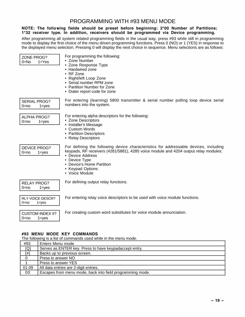
PROGRAMMING WITH #93 MENU MODENOTE: The following fields should be preset before beginning: 2*00 Number of Partitions;1*32 receiver type. In addition, receivers should be programmed via Device programming.
After programming all system related programming fields in the usual way, press #93 while still in programmingmode to display the first choice of the menu driven programming functions. Press 0 (NO) or 1 (YES) in response tothe displayed menu selection. Pressing 0 will display the next choice in sequence. Menu selections are as follows:
ZONE PROG?0=No 1=Yes
For programming the following:• Zone Number• Zone Response Type• Hardwired zone• RF Zone• Right/left Loop Zone• Serial number RPM zone• Partition Number for Zone• Dialer report code for zone
SERIAL PROG?0=no 1=yes
For entering (learning) 5800 transmitter & serial number polling loop device serialnumbers into the system.
ALPHA PROG?0=no 1=yes
For entering alpha descriptors for the following:• Zone Descriptors• Installer's Message• Custom Words• Partition Descriptors• Relay Descriptors
DEVICE PROG?0=no 1=yes
For defining the following device characteristics for addressable devices, includingkeypads, RF receivers (4281/5881), 4285 voice module and 4204 output relay modules:• Device Address• Device Type• Device's Home Partition• Keypad Options• Voice Module
RELAY PROG?0=no 1=yes
For defining output relay functions.
RLY VOICE DESCR?0=no 1=yes
For entering relay voice descriptors to be used with voice module functions.
CUSTOM INDEX #?0=no 1=yes
For creating custom word substitutes for voice module annunciation.
#93 MENU MODE KEY COMMANDSThe following is a list of commands used while in the menu mode. #93 Enters Menu mode
[Q] Serves as ENTER key. Press to have keypadaccept entry.[#] Backs up to previous screen.0 Press to answer NO1 Press to answer YES
01-09 All data entries are 2-digit entries.00 Escapes from menu mode, back into field programming mode.
Ð 20 Ð
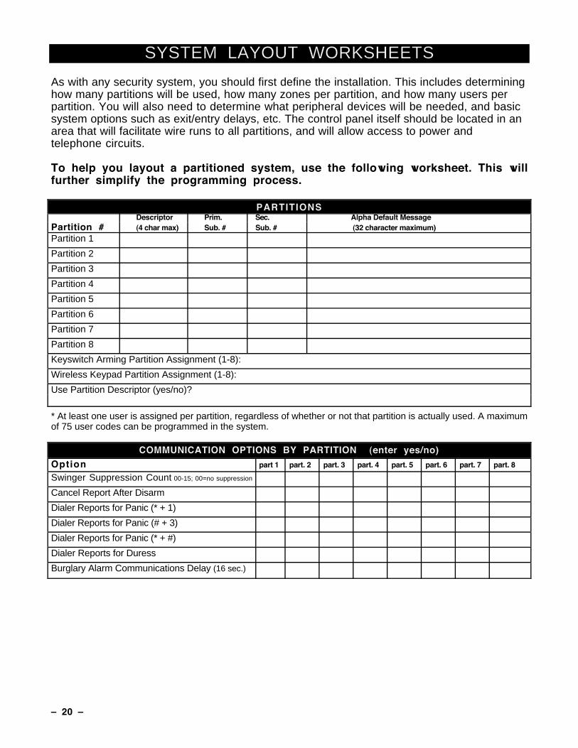
SYSTEM LAYOUT WORKSHEETS
As with any security system, you should first define the installation. This includes determininghow many partitions will be used, how many zones per partition, and how many users perpartition. You will also need to determine what peripheral devices will be needed, and basicsystem options such as exit/entry delays, etc. The control panel itself should be located in anarea that will facilitate wire runs to all partitions, and will allow access to power andtelephone circuits.
To help you layout a partitioned system, use the following worksheet. This willfurther simplify the programming process.
PARTITIONSDescriptor Prim. Sec. Alpha Default Message
Partition # (4 char max) Sub. # Sub. # (32 character maximum)
Partition 1
Partition 2
Partition 3
Partition 4
Partition 5
Partition 6
Partition 7
Partition 8
Keyswitch Arming Partition Assignment (1-8):
Wireless Keypad Partition Assignment (1-8):
Use Partition Descriptor (yes/no)?
* At least one user is assigned per partition, regardless of whether or not that partition is actually used. A maximumof 75 user codes can be programmed in the system.
COMMUNICATION OPTIONS BY PARTITION (enter yes/no)
Option part 1 part. 2 part. 3 part. 4 part. 5 part. 6 part. 7 part. 8
Swinger Suppression Count 00-15; 00=no suppression
Cancel Report After Disarm
Dialer Reports for Panic (* + 1)
Dialer Reports for Panic (# + 3)
Dialer Reports for Panic (* + #)
Dialer Reports for Duress
Burglary Alarm Communications Delay (16 sec.)
Ð 21 Ð
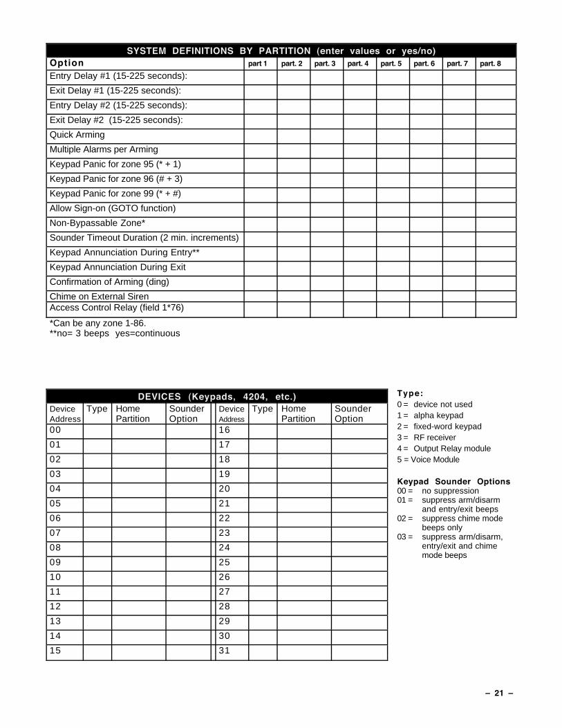
SYSTEM DEFINITIONS BY PARTITION (enter values or yes/no)Option part 1 part. 2 part. 3 part. 4 part. 5 part. 6 part. 7 part. 8
Entry Delay #1 (15-225 seconds):
Exit Delay #1 (15-225 seconds):
Entry Delay #2 (15-225 seconds):
Exit Delay #2 (15-225 seconds):
Quick Arming
Multiple Alarms per Arming
Keypad Panic for zone 95 (* + 1)
Keypad Panic for zone 96 (# + 3)
Keypad Panic for zone 99 (* + #)
Allow Sign-on (GOTO function)
Non-Bypassable Zone*
Sounder Timeout Duration (2 min. increments)
Keypad Annunciation During Entry**
Keypad Annunciation During Exit
Confirmation of Arming (ding)
Chime on External SirenAccess Control Relay (field 1*76)
*Can be any zone 1-86.**no= 3 beeps yes=continuous
DEVICES (Keypads, 4204, etc.)Device Type Home Sounder Device Type Home SounderAddress Partition Option Address Partition Option00 16
01 17
02 18
03 19
04 20
05 21
06 22
07 23
08 24
09 25
10 26
11 27
12 28
13 29
14 30
15 31
Type:0 = device not used1 = alpha keypad2 = fixed-word keypad3 = RF receiver4 = Output Relay module5 = Voice Module
Keypad Sounder Options00 = no suppression01 = suppress arm/disarm
and entry/exit beeps02 = suppress chime mode
beeps only03 = suppress arm/disarm,
entry/exit and chimemode beeps

Ð 22 Ð
ACCESS CODES & USER DEFINITIONS FOR PARTITIONS 1-34-digit Access Partition 1 Partition 2 Partition 3Security Group 2-digit Auth. open/ Global 2-digit Auth. open/ Global 2-digit Auth. open/ GlobalCode 0; 1-8 user # level close Arm? user # level close Arm? user # level close Arm?
ACCESS CODES & USER DEFINITIONS FOR PARTITIONS 4-64-digit Access Partition 4 Partition 5 Partition 6Security Group 2-digit Auth. open/ Global 2-digit Auth. open/ Global 2-digit Auth. open/ GlobalCode 0; 1-8 user # level close Arm? user # level close Arm? user # level close Arm?
ACCESS CODES & USER DEFINITIONS FOR PARTITIONS 7 & 84-digit Access Partition 7 Partition 8Security Group 2-digit Auth. open/ Global 2-digit Auth. open/ Global 2-digit Auth. open/ GlobalCode 0; 1-8 user # level close Arm? user # level close Arm? user # level
close Arm?
Authority Levels: 1=master (arm, disarm, bypass, and/or modify lower level users)2=manager (arm, disarm, bypass, and/or modify lower level users)3=operator A (arm, disarm, bypass)4=operator B (arm, disarm)5=operator C (arm, disarm only if system was armed with this code)6=duress code (arm, disarm, triggers silent panic alarm)
Ð 23 Ð
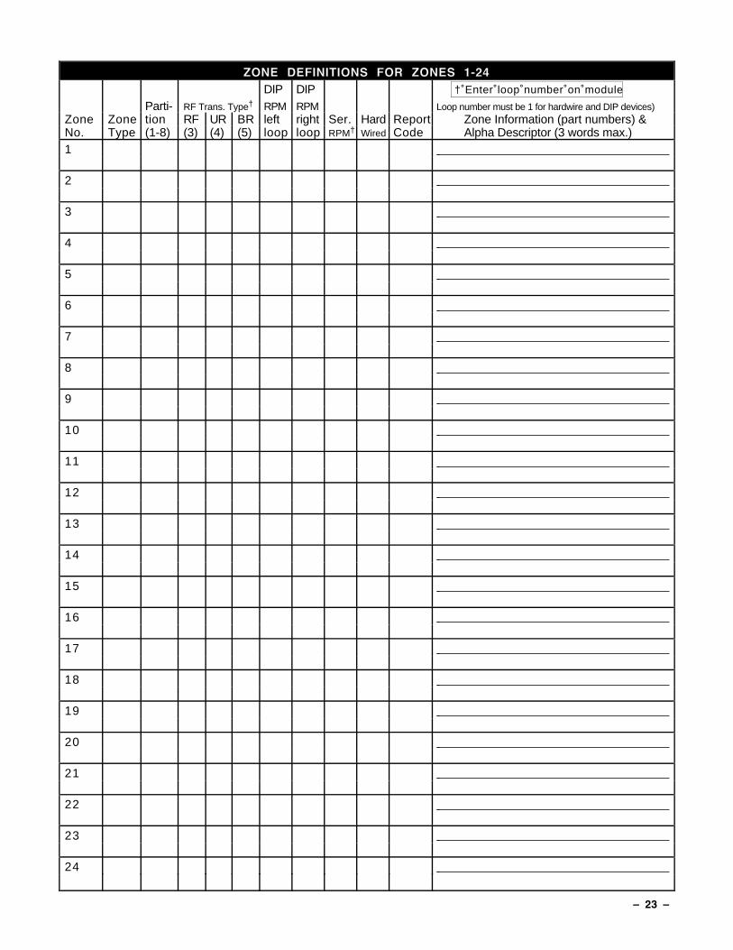
ZONE DEFINITIONS FOR ZONES 1-24DIP DIP † Enter loop number on module
Parti- RF Trans. Type† RPM RPM Loop number must be 1 for hardwire and DIP devices)Zone Zone tion RF UR BR left right Ser. Hard Report Zone Information (part numbers) &No. Type (1-8) (3) (4) (5) loop loop RPM† Wired Code Alpha Descriptor (3 words max.)1
2
3
4
5
6
7
8
9
10
11
12
13
14
15
16
17
18
19
20
21
22
23
24
Ð 24 Ð
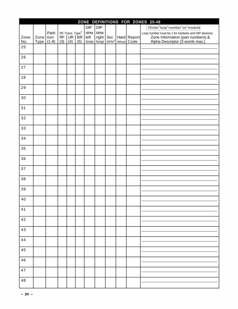
ZONE DEFINITIONS FOR ZONES 25-48DIP DIP †Enter loop number on module
Parti- RF Trans. Type† RPM RPM Loop number must be 1 for hardwire and DIP devices)Zone Zone tion RF UR BR left right Ser. Hard Report Zone Information (part numbers) &No. Type (1-8) (3) (4) (5) loop loop RPM† Wired Code Alpha Descriptor (3 words max.)25
26
27
28
29
30
31
32
33
34
35
36
37
38
39
40
41
42
43
44
45
46
47
48
Ð 25 Ð
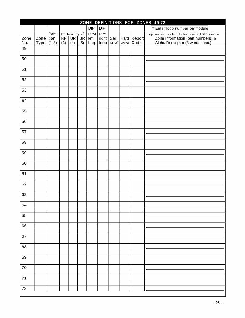
ZONE DEFINITIONS FOR ZONES 49-72DIP DIP † Enter loop number on module
Parti- RF Trans. Type† RPM RPM Loop number must be 1 for hardwire and DIP devices)Zone Zone tion RF UR BR left right Ser. Hard Report Zone Information (part numbers) &No. Type (1-8) (3) (4) (5) loop loop RPM† Wired Code Alpha Descriptor (3 words max.)49
50
51
52
53
54
55
56
57
58
59
60
61
62
63
64
65
66
67
68
69
70
71
72
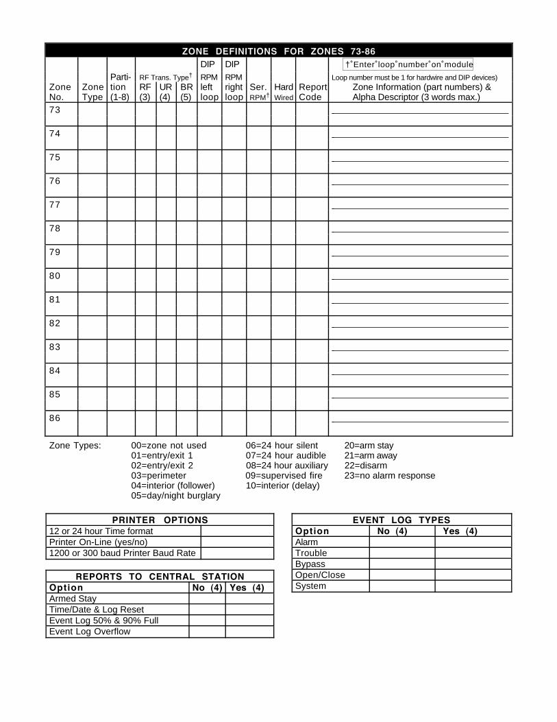
ZONE DEFINITIONS FOR ZONES 73-86DIP DIP † Enter loop number on module
Parti- RF Trans. Type† RPM RPM Loop number must be 1 for hardwire and DIP devices)Zone Zone tion RF UR BR left right Ser. Hard Report Zone Information (part numbers) &No. Type (1-8) (3) (4) (5) loop loop RPM† Wired Code Alpha Descriptor (3 words max.)73
74
75
76
77
78
79
80
81
82
83
84
85
86
Zone Types: 00=zone not used 06=24 hour silent 20=arm stay01=entry/exit 1 07=24 hour audible 21=arm away02=entry/exit 2 08=24 hour auxiliary 22=disarm03=perimeter 09=supervised fire 23=no alarm response04=interior (follower) 10=interior (delay)05=day/night burglary
PRINTER OPTIONS12 or 24 hour Time formatPrinter On-Line (yes/no)1200 or 300 baud Printer Baud Rate
REPORTS TO CENTRAL STATIONOption No (4) Yes (4)Armed StayTime/Date & Log ResetEvent Log 50% & 90% FullEvent Log Overflow
EVENT LOG TYPESOption No (4) Yes (4)AlarmTroubleBypassOpen/CloseSystem

Ð 27 Ð
NOTES:

ALARM DEVICE MANUFACTURING CORPORATIONA DIVISION OF PITTWAY CORPORATION
165 Eileen Way, Syosset, New York 11791Copyright © 1994 PITTWAY CORPORATION


![Myth of Junk DNA Notes [50p]](https://img.pdfslide.us/doc/110x75/5532f56d4a79595c598b47c8/myth-of-junk-dna-notes-50p.jpg)