Embed Size (px)
Citation preview


2 AUCOM
MVX
Smaller size: The overall form factor is 60%
smaller than our previous product MVS. The
MVX is among the smallest medium voltage soft
starter in its class. Smaller size is a big advantage
in lowering the costs in building and provides
more flexibility where space is limited, for
example marine applications.
InCreAsed sAfety
To ensure that your staff and plant are safe from
arc faults, MVX is the only choice. MVX meets
or exceeds all the relevant standards:
• IEC62271-200 for switchgear and apparatus, and internal arc fault resistance
• IEC62271-304 for switchgear and apparatus
• IEC60664-1 for electrical insulation
eAsIer tO serVICe
AuCom has eliminated complex disassembly
to replace or service a part, AuCom MVX
panels are designed with easy rack in-rack out
operation, and components are easily accessible
via hinged doors or removable panels while still
keeping unauthorised people out.
MOre fleXIbIlIty
Don’t feel constrained in the choice of apparatus
in your switchgear, AuCom panels are compat-
ible with all of the major apparatus suppliers.
the benefIt Of eXperIenCe
At every stage of the process your AuCom
team will work hard to create the ideal AuCom
solution to meet the needs of your application
and budget.
MVX
Viewing window to
inspect fuses, earth
switch etc without
opening doors
Bus bars isolated in
separate compartment

3VIsIt WWW.AUCOM.COM fOr MOre InfOrMAtIOn
Interlocking racking
system for VCBs etc
AuCom keypad and
analog/digital metering
options available
Modular design
allows for single
panels or line-ups
Safe LV compartment
access without need
to de-energise MV
section
Viewing window to
inspect fuses, earth
switch etc without
opening doors
Internal separation
compartments isolate
bus work during LV
service
Arc fault resistant
enclosure
Easy to
manoeuvre and
install via lifting
eye bolts
Hinged door panels
(no more lost or
damaged panels)
Small footprint phase
cassette
Lockable doors as
standard
Two step door locking
prevents accidental
access

4 AUCOM
SofT STArTEr PHASE CASSETTE fEATurES
Self-contained phaSe caSSette
rACk-In/rACk-OUt
AuCom MVX soft starters are fully self-
contained and easily serviced/replaced.
AuCom can include a service trolley
that enables one person to remove and
replace the starter. Phase cassettes are
installed via a rolling base which is easily
integrated for oEM solutions.
stAndArd COMpAtIbIlIty
All panels are constructed around
150 mm pole centres for compatibility
with standard apparatus options from
major suppliers. Soft starters are also
built to plug in/out easily.
sMAll fOOtprInt
The compact size of the starter allows
for a smaller overall panel dimension to
save space in your switch room. robust
construction allows for reliable use in
even the most demanding industrial
locations.
Small footprint ip00 Starter
rack-in/rack-out phaSe caSSetteS
Standard 150 mm pole centreS
Gp06 and air inSulation
iSolated control via fibre optic connectionS

5VIsIt WWW.AUCOM.COM fOr MOre InfOrMAtIOn
KEyPAD
reAl lAngUAge
The MVX features simple, plain language
feedback on the soft starter’s operation
and events – no trip code look-ups. The
MVX has language options for operation
in English and Chinese.
eAsy tO reAd sCreen
The MVX has a real-language display,
offering extensive feedback and real-time
status information in an easy-to-read
format. Comprehensive metering infor-
mation, details of starter status and last
start performance allow easy monitoring
of the starter’s performance at all times
Multiple status screens let you display the
data most relevant to your application,
or you can configure your own program-
mable screen to show the most relevant
information for your application.
eVent lOgs
A 99 position event log records all infor-
mation on the starter’s operating history,
in separate event and trip logs to assist
in troubleshooting. An eight position
trip log records trip states and operating
conditions at the time of trip.
• Phasecurrentsandvoltages
• Mainsfrequency
• Starterstate
• Timeanddate
multilinGual controller for operation in enGliSh and Simplified chineSe
all controlS centrally located on a SinGle panel
StatuS ledS for immediate feedback
Start, Stop, reSet, local/remote puSh buttonS
Shortcut buttonS for quick acceSS to common taSkS
ip65 keypad mounted on cabinet exterior
clear, eaSy to read Screen
emerGency Stop button
CentrAlIsed COntrOl
All control of the soft starter is avail-
able from the single controller. The
graphical display even allows real-time
graphing of the starter operation.
Isolated control is provided via fibre
optic connections between the LV
and MV sections.
6 AUCOM
K2M
E
A3A2
T3
T2
T1
L3
L2
L1
T3B
T2B
T1B
A1
110~240 VAC - 15+ 10
TXRX
RXTX
-+
33
34
C74
C73
C42
C41
B11
B10
61
62
64
51
52
54
44
43
24
23
14
13
B5
B4
C64
C63
C54
C53
C32
C31
C24
C23
A4
A6
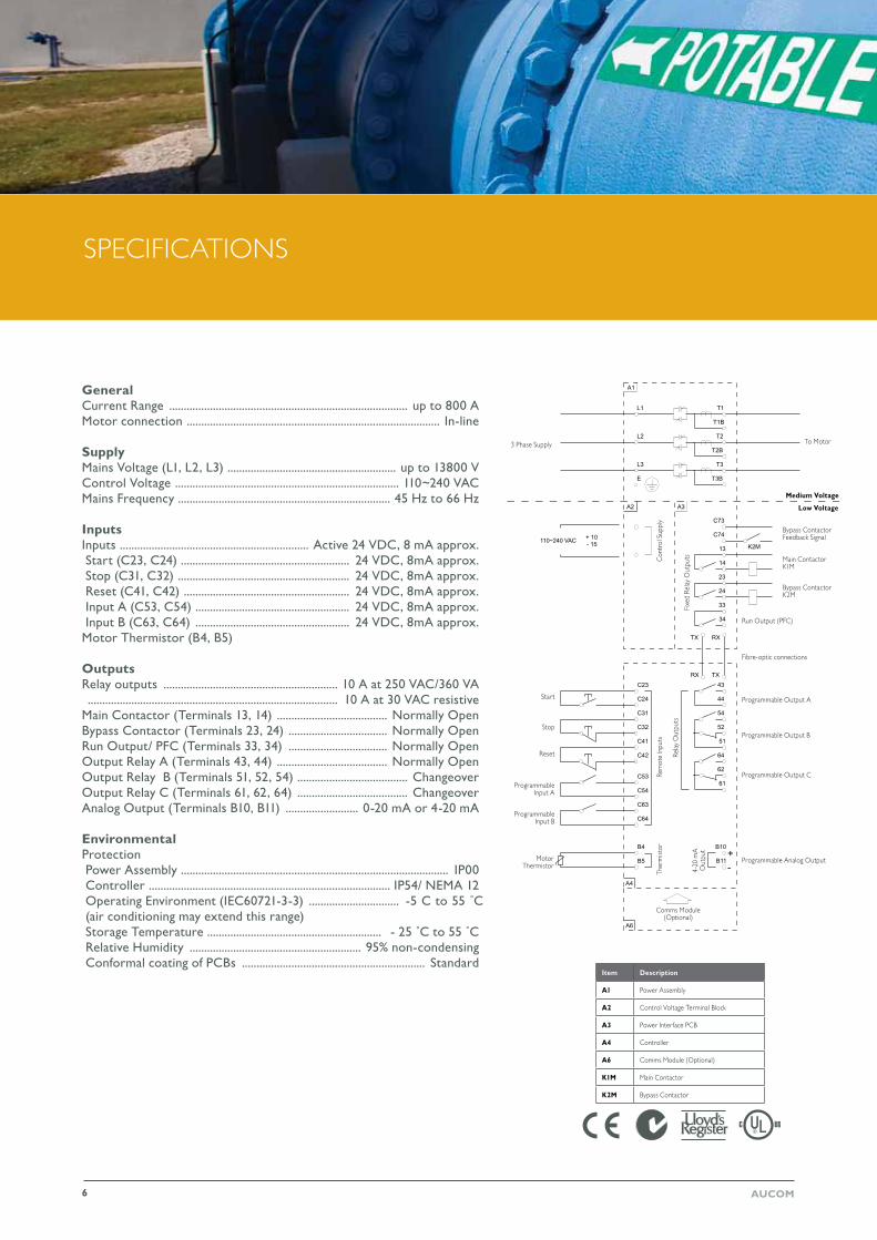
SPECIfICATIoNS
Item description
A1 Power Assembly
A2 Control Voltage Terminal Block
A3 Power Interface PCB
A4 Controller
A6 Comms Module (optional)
k1M Main Contactor
k2M Bypass Contactor
To Motor3 Phase Supply
Medium Voltage
low Voltage
Bypass Contactor feedback Signal
Main Contactor K1M
Bypass Contactor K2M
run output (PfC)
Programmable output A
Programmable output B
Programmable output C
Programmable Analog output
Comms Module (optional)
Motor Thermistor
Programmable Input B
Programmable Input A
reset
Stop
Start
Ther
mist
orre
mot
e In
puts
rela
y o
utpu
ts
4-20
mA
o
utpu
t
Con
trol
Sup
ply
fixe
d re
lay
out
puts
GeneralCurrent Range .................................................................................. up to 800 AMotor connection ....................................................................................... In-line
SupplyMains Voltage (L1, L2, L3) .......................................................... up to 13800 VControl Voltage ............................................................................. 110~240 VACMains Frequency ......................................................................... 45 Hz to 66 Hz
InputsInputs ................................................................. Active 24 VDC, 8 mA approx. Start (C23, C24) .......................................................... 24 VDC, 8mA approx. Stop (C31, C32) ........................................................... 24 VDC, 8mA approx. Reset (C41, C42) ......................................................... 24 VDC, 8mA approx. Input A (C53, C54) ..................................................... 24 VDC, 8mA approx. Input B (C63, C64) ..................................................... 24 VDC, 8mA approx.Motor Thermistor (B4, B5)
OutputsRelay outputs ............................................................ 10 A at 250 VAC/360 VA ...................................................................................... 10 A at 30 VAC resistiveMain Contactor (Terminals 13, 14) ...................................... Normally OpenBypass Contactor (Terminals 23, 24) .................................. Normally OpenRun Output/ PFC (Terminals 33, 34) .................................. Normally OpenOutput Relay A (Terminals 43, 44) ...................................... Normally OpenOutput Relay B (Terminals 51, 52, 54) ...................................... ChangeoverOutput Relay C (Terminals 61, 62, 64) ...................................... ChangeoverAnalog Output (Terminals B10, B11) ......................... 0-20 mA or 4-20 mA
EnvironmentalProtection Power Assembly ............................................................................................ IP00 Controller ................................................................................... IP54/ NEMA 12 Operating Environment (IEC60721-3-3) ............................... -5 C to 55 ˚C (air conditioning may extend this range) Storage Temperature ............................................................ - 25 ˚C to 55 ˚C Relative Humidity ........................................................... 95% non-condensing Conformal coating of PCBs ............................................................... Standard
fibre-optic connections

7VIsIt WWW.AUCOM.COM fOr MOre InfOrMAtIOn
2200
1060
1671
1567
2200
1060
1671
1567
DIMENSIoNS
phAse CAssettes
pAnels
882
563.
2
1078.9

8 AUCOM
pAnel COMpArtMents
Each panel consists of four compart-
ments: Bus bar compartment, cable compartment, circuit breaker compart-ment and the instrument compartment
The bus bar compartment houses the
main bus bar system connected to the
fixed upper isolating contacts of the
circuit breaker by means of branch
connections.
The cable compartment houses the con-
nection of the power cables to the bus
bar. The earthing switch, surge arresters,
voltage and current transformers can be
installed here.
The circuit breaker compartment houses
the bushing insulators containing fixed
contacts for the connection of the circuit
breaker with the bus bar and the cable
compartment.
COMpArtMent segregAtIOn
Metallic shutters and partitions segregate
the compartments from each other.
When a compartment is opened all
other panels in the installation and all
cable termination compartments (includ-
ing that in the panel concerned) remain
in operation.
Metallic shutters automatically protect high voltage components when the circuit breaker is withdrawn.
All switching operations can be per-
formed with the doors closed and the
position of the circuit breaker can be
seen from the front of the panel through
a pressure-resistant inspection window.
AVAIlAbIlIty And pArtItIOn
L-Series panels are designed in compli-
ance with availability classes LSC2B
and partition class PM according to IEC
62271-200.
The switchgear compartments do not
need any tools for opening. Interlocks
allow access only when the correspond-
ing high voltage parts are dead and
earthed.
PANEL CoMPArTMENTS
Enclosure
Low voltage compartment
Circuit breaker compartment
Shutter
Vacuum circuit breaker
Door lock
Door handleInspection window
Cable compartmentEarthing switch
Current transformer
fixed contact insulator
Bus bar system
Bushing
overpressure flap

9VIsIt WWW.AUCOM.COM fOr MOre InfOrMAtIOn
internal arc fault test, 31.5ka/1s
type test reports
SAfETy
ArC fAUlt
An arc fault is a high power discharge
of electricity between two or more
conductors. The event can reach
temperatures of 10,000° C, hot enough
toliquefyceramics,plasticsandmetal.
The arc fault causes a sudden increase in
pressure, followed by an expansion, emis-
sion phase and finally a thermal phase.
This can blast the debris and combustible
gas outward with extreme force.
The internal pressure against the weakest
points of the enclosure (e.g. windows,
hinges and joints) can destroy an electri-
cal enclosure and may cause serious or
fatal injury to nearby personnel.
Arc faults can occur for a number of
reasons, usually overvoltage, faulty
insulation, mechanical failure or failure of
a fuse.
ArC fAUlt prOteCtIOn
If an arc event occurs within an AuCom
L-Series panel, the arc fault is contained
by solid locking doors and heavy double
layer compartment panels.
During the emission phase the pressure
is safely released using discharge flaps on
the top of the panel (or optional ducts).
These direct the explosion upwards or
vent it safely outside.
Arc fault events normally occur in less
than a second, so not even the fastest
person is able to react to protect
themselves. However pressure discharge
flaps will react in milliseconds to allow
the heated gases to vent.
responsible specifiers should ensure that
theyrequireallswitchgeartomeetIEC
62271-200. L-Series panels are suited for
Internal Arc Classification (IAC) AfLr to
a maximum of 31.5 kA for 1 second.
tests
AuCom L-Series panels have passed arc
fault tests for the entire range of panel
enclosures. (Type test certificates are
availableonrequest).Thepanelswill
even pass arc fault tests with low voltage
compartment doors open.
All L-Series panels are fully type tested
according to IEC 62271-200:
• Short time and peak withstand current
• Temperature rise and main circuit impedance
• Dielectric test on main and auxiliary circuits
• Making and breaking capacity of the circuit breaker within the panel
• Earthing switch making capacity
• Mechanical operations
• Internal arc fault (IAC classified: AfLr, 31.5A/1s)

10 AUCOM
TESTINg AND SIMuLATIoN
lOW VOltAge testIng
The MVX can be connected to a low
voltage motor (≤ 500 VAC) for testing.
This allows the user to thoroughly test
the soft starter and its associated power
and control circuits. The low voltage test
mode provides a means of testing the soft
starter’sconfigurationwithoutrequiringa
full medium voltage test facility.
sOftWAre sIMUlAtIOns
The simulations function allow the MVX
to be tested without a motor connected,
to confirm that the soft starter’s control
circuits are operating correctly. There are
three simulation modes available:
• run simulation: simulates a motor starting, running and stopping to confirm correct configuration of main and bypass contactors, fibre-optic con-trols, programmable relays and motor control signals.
• Protection simulation: simulates activa-tion of each protection mechanism to confirm that the soft starter is responding correctly in each situation.
• Signalling simulation: simulates output signalling to confirm configuration.
AuCom selects each MVX to suit your
needs. Choose a starter to suit your
site conditions such as altitude, ambient
temperature, load, and starts per hour.
AuCom MVX ratings are detailed using
the AC53b utilisation code. An example
is shown below.
stArter CUrrent rAtIng
The full load current rating of the soft
starter given the parameters detailed in
the remaining sections of the utilisation
code.
stArt CUrrent
The maximum available start current as a
multiple of fLC.
stArt tIMe
Themaximumtimerequiredtostartthe
motor at the rated start current..
Off tIMe
The minimum allowable time between
the end of one start and the beginning of
the next start.
165 A: AC-53b 5-30 : 1770
off time (seconds)
Start current (multiple of fLC)
Start current rating (Amps)
Start time (seconds)
rATINgS

11VIsIt WWW.AUCOM.COM fOr MOre InfOrMAtIOn
prOteCtIOn
A wide range of protection features
ensureyourequipmentcanoperate
safely in the most demanding environ-
ments. Each protection can be individu-
allyadjustedtotherequiredsensitivity,
orcanbedisabledifrequiredtoensure
vitalequipmentcontinuestooperate
even in the most challenging situations.
trIps
Trips and warnings are written to
an eight-place trip log, together with
information on motor and system status
at the time, speeding up analysis of
problems.
therMAl CApACIty
The thermal model will only permit a
start which is predicted to succeed. This
protects the motor against overloads
which shorten the motor life.
AdVAnCed therMAl MOdellIng
Intelligent thermal modelling allows the
soft starter to dynamically calculate
motor temperature to predict whether
the motor can successfully complete a
start. The MVX uses information from
previous and upcoming starts to calculate
the motor temperature to predict the
motor’s available thermal capacity.
pAssWOrd prOteCtIOn
A multi-level password system provides
security for parameter adjustments while
still allowing users full access to the many
metering functions.
fIbre OptICs
Electrical isolation of low and high
voltage circuits is assured by a two line
fibre-optic interface between the power
assembly and the control module. This
fibre-optic link simplifies installation of
chassis mount MVX units into custom
switchboards.
prOteCtIOn COdes
ProTECTIoN
desIgn
• Depending on the design all compart-ments are accessible from the front. Alternatively the cable compartment is accessible from the rear.
• Cable connection points are all at comfortable height.
• Cable and circuit breaker compart-ments include pressure resistant inspection windows as standard.
• fully flexible cabling and bus bar entry option
• Created for simple, straightforward manufacturing: No welding, balancing, grinding or cleansing procedures are required.
• Segregated bus bars from panel to panel.
• optional arc venting shields or gas exhaust duct available.
AnsI Code
description MVX protection (built-in)
48 Maximum start time Excess start time
66 Too many starts restart delay and dynamic thermal model
37 undercurrent undercurrent
51L Load Increase (alarm) Highcurrentfrequencyoutput
51r overcurrent - jam Excess start time, electronic shearpin
50 overcurrent - short Shorted SCr, electronic shearpin
49/51 Thermal overload Thermal overload - dynamic model
46 Current imbalance Current imbalance
Positive/negativephasesequence Phasesequence
27 undervoltage undervoltage
59 overvoltage overvoltage
47 Phase loss Phase loss
47 Phasesequence Phasesequence
50g ground fault ground fault
85 Communications failure Communications failure
85 Internal failure Internal failure
94/95 Ext. fault 1/code - 1 Auxilary trip A
Ext. fault 1/code - 2 Auxilary trip B
23 Motor overtemperature Thermistor protection*
49 Stator winding overtemperature Thermistor protection*
32 under power Power Loss
* rTD relay is an optional extra.

12 AUCOM
IsOlAtIOn
MVX panels use a combination of air and
gP03 insulation and features to ensure
personnel safety when working in the
MV environment. unlike messy oil or
water insulation, gP03 is able to provide
a smaller overall dimension without the
hassle or reliability issues.
fibre-optic insulation between the low
voltage controller and the high voltage
power assembly provides complete
electrical isolation.
enClOsUre
The enclosure is made of corrosion
resistant hot dip galvanized steel sheets.
Its design allows fast assembly with bolts
only. No welding, balancing, grinding or
cleansing is necessary, and no jigs are
requiredforassembly.
Eachpanelisequippedwithsidewalls.
The special design provides an 8 mm air
gap between two neighbouring panels. In
the unlikely event of an internal arc, this
design assures that the damage is limited
to the panel where the fault occurred.
dOOrs & lOCks
The coated doors are made from
galvanized sheet steel. robust hinges
and handles provide for convenient and
safe closing. The closing mechanisms are
available for left or right hand operation.
Every compartment door has built-in
locking as standard. Tags may also be
applied to indicate sections with work in
progress.
rounded edges guarantee safe handling interlock for circuit breaker compartment door Swinghandle locks on the doors provide additional safety
SAfETy fEATurES

13VIsIt WWW.AUCOM.COM fOr MOre InfOrMAtIOn
100%
10%
20%
30%
40%
50%
60%
70%
80%
90%
100%
10%
20%
30%
40%
50%
60%
70%
80%
90%
100%
10%
20%
30%
40%
50%
60%
70%
80%
90%
COnstAnt CUrrent
Suitable for most applications. Current
is raised to specified level and held for
duration of start.
CUrrent rAMp
Better for generator sets or if conditions
may vary between starts.
kICkstArt
Providesashortbootoftorqueatthe
beginning of the start.
STArTINg AND SToPPINg oPTIoNS
COAst tO stOp
removes voltage from motor and allows
inertial slowing.
tIMed VOltAge rAMp
gradually reduces voltage to extend
deceleration time.
pUMp COntrOl stOp
Provides gradual deceleration to reduce
fluid hammer.
full Voltage Current
Current Limit
Cur
rent
(%
Mot
or f
ull L
oad
Cur
rent
)
rotor Speed (% full Speed)
full Voltage Current
Current Limit
Start ramp Time
Initial Start Current
Cur
rent
(%
Mot
or f
ull L
oad
Cur
rent
)
rotor Speed (% full Speed)
full Voltage Current
Current LimitStart ramp Time
Initial Start Current
Kickstart level
Kickstart time
Mot
or S
peed
Time (seconds)
Mot
or S
peed
Time (seconds)
Mot
or S
peed
Time (seconds)
Pump Control StopTVr Soft Stop
Coast to Stop
Cur
rent
(%
Mot
or f
ull L
oad
Cur
rent
)
rotor Speed (% full Speed)

14 AUCOM
Surge arresters
EquIPMENT oPTIoNS
eArthIng sWItCh
Each feeder compartment can be
equippedwithanearthingswitchfor
cable earthing.
When installed in measurement, bus-tie
or bus riser panels it can also be used to
earth the bus bar system.
The earthing switch has short circuit
making capacity. The position of the
earthing switch can be seen by means
of mechanical position indication and in
addition through an inspection window.
sWItChIng And prOteCtIOn
• Earth Switch
• Vacuum Circuit Breakers
• fuse contactor
• MoVs
Apparatus is easily installed by one
person using the AuCom Service trolley.
Equipmentisrolledontotheservice
trolley and rolls into the panel via small
track connectors.
COMMUnICAtIOns
The MVX integrates into your existing
monitoring and control network, using
easy-to-install plug-in communication
interfaces. The MVS supports Profibus,
DeviceNet and Modbus rTu protocols.
These modules are an optional extra.
pOWer fACtOr COrreCtIOn OptIOns
• Capacitors
• Inductors
• fuses
• Contactors
AUXIlIAry MOdUles
• Measurement and protection current transformers
• Power meters
• Protection relays
• rTDs
• Inductive voltage transformers
• Panel heat pump
• Surge protection
• Protection relays
sUrge Arresters
In the cable compartment space is
provided for three fix mounted surge
arresterstoprotecttheequipmentfrom
switching overvoltages.
make-proof earthing switch modbus, profibus, devicenet and uSb interface modules
15VIsIt WWW.AUCOM.COM fOr MOre InfOrMAtIOn
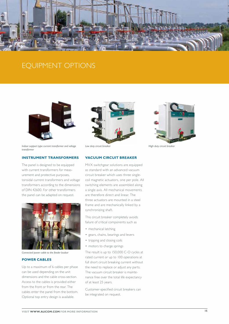
low duty circuit breaker high duty circuit breaker
InstrUMent trAnsfOrMers
Thepanelisdesignedtobeequipped
with current transformers for meas-
urement and protective purposes,
toroidal current transformers and voltage
transformers according to the dimensions
of DIN 42600. for other transformers
thepanelcanbeadaptedonrequest.
pOWer CAbles
up to a maximum of 6 cables per phase
can be used depending on the unit
dimensions and the cable cross-section.
Access to the cables is provided either
from the front or from the rear. The
cables enter the panel from the bottom.
optional top entry design is available.
VACUUM CIrCUIt breAker
MVXswitchgearsolutionsareequipped
as standard with an advanced vacuum
circuit breaker which uses three single-
coil magnetic actuators, one per pole. All
switching elements are assembled along
a single axis. All mechanical movements
are therefore direct and linear. The
three actuators are mounted in a steel
frame and are mechanically linked by a
synchronizing shaft.
This circuit breaker completely avoids
failure of critical components such as
• mechanical latching
• gears, chains, bearings and levers
• tripping and closing coils
• motors to charge springs
The result is up to 150,000 C-o cycles at
rated current or up to 100 operations at
full short circuit breaking current without
the need to replace or adjust any parts.
The vacuum circuit breaker is mainte-
nance free over the total life expectancy
of at least 25 years.
Customer-specified circuit breakers can
beintegratedonrequest.
indoor support type current transformer and voltage transformer
connected power cable to the feeder busbar
EquIPMENT oPTIoNS

oTHEr AuCoM ProDuCTS
An advanced soft start controller designed for use in motor control centres. Easily incorporated into any control circuit and suitable for use with any type of motor protection device.
CsX sOft stArt COntrOller
A compact soft starter providing constant current soft start control and essential motor protection. A complete motor control solution in a single compact design.
CsXI COMpACt sOft stArter
A complete motor management system providing constant current, and current ramp as well as the new XLr-8, Adaptive Acceleration Control, available only from AuCom.
eMX3 AdVAnCed sOft stArter
An advanced motor
management system for
medium voltage motors.
MVS soft starters provide
a full range of soft start
control, motor/load
protection and other
features.
MVs MedIUM VOltAge sOft stArter
AuCom offers a complete range of soft starters, with a solution for your soft starting requirement. Whether you need a simple product for starting only, or a comprehensive solution for your motor control and protection needs, you can trust AuCom to offer a product to match.
AuCom electronics ltd. 123 Wrights road
Po Box 80208 Christchurch 8440
New Zealand t +64 3 338 8280 f +64 3 338 8104
e [email protected] W www.aucom.com
For more information on AuCom products, contact your local distributor:
© 2011 AuCom Electronics. As AuCom is continuously improving its products it reserves the right to modify or change the specification of its products at any time without notice. The text, diagrams, images and any other literary or artistic works appearing in this brochure are protected by copyright. Users may copy some of the material for their personal reference but may not copy or use material for any other purpose without the prior consent of AuCom Electronics Ltd. AuCom endeavours to ensure that the information contained in this brochure including images is correct but does not accept any liability for error, omission or differences with the finished product.
710-11442-00B
* higher ratings available on request.
soft start
Motor protection
Advanced Interface
Internal bypass
power range
Voltage range
CSX • • ≤ 200 A ≤ 575 VAC
CSXi • • • ≤ 200 A ≤ 575 VAC
IMS2 • • • ≤ 2361 A ≤ 690 VAC
EMX3 • • • • ≤ 2400 A ≤ 690 VAC
MVS • • • • ≤ 600 A * ≤ 13.8 kV
MVX • • • • ≤ 800 A * ≤ 15 kV