Embed Size (px)
DESCRIPTION
VISION tilting table is a radiological device, which properly connected tospecific accessories like Image Intensifiers (I.I.) with TV chains allows tocarry out radiological investigation under fluoroscopy or radiographymode.Making use of these modality, it is possible to perform generalradiological investigations and special tests using contrast liquid means.Exams of bones, digestive function, double contrast, enema, urologicalradiography and all fluoroscopic investigations can be performed withthis device.VISION table is designed to be connected to new sophisticated digitalacquisition systems allowing angiographic as well as flebographyexaminations.
Citation preview

Release 9 April 2004 (Rev. 4)
VISIONVISIONVISIONVISION 0051
Service manualService manualService manualService manual

This Manual belongs to Vision equipment serial No. ……………………
Release 9 April 2004 (Rev. 4)
VISIONVISIONVISIONVISION 0051
Service manualService manualService manualService manual

SERVICE MANUALRevision history
(Rev. 4) VISION
Revision historyRevision historyRevision historyRevision history
Rev. Date Page/s Modification description
0 07.08.00 Document approval.
1 19.01.01 All ETL certification.Deletion of the electrical check of Pottercall voltage set-up.Software release check description.Schematics update.Configuration default parameter update.Complete revision.(Ref. RDM 5031, 5050, 5054, 5059, 5064, 5070)
2 21.06.01 i, ii, iii, iv, 3-2, from 7-2 to 7-8,7-10, 7-11, from 10-3 to 10-6,11-26, 11-31, 13-5, 13-7, from22-5 to 22-31, 22-41, 22-47,from 22-55 to 22-85, 22-103,
22-105
New software release.Fluoroscopy foot-switch predisposition.Schematics update.(Ref. RDM 5110, 5128, 5132, 5156, 5195)
3 11.01.02 3-2, 8-2, 8-3, from 22-5 to22-31, 22-51
New Potter Bucky SD version(120/230V power supply)(Ref. RDM 5216, 5227, 5332)
4 09.04.04 3-2, 4-9, 5-5, 11-22,11-31, 22-53
Implementation of Gilardoni MeasuringChamber (AEC).Notify body change for CE mark.Software update for collimatoradjustment during Fluoroscopy.(Ref. RDM 5463, RDM 5781, RDM 5791)
5

SERVICE MANUALRevision history
VISION (Rev. 2)
THIS PAGE IS INTENTIONALLY LEFT BLANK
SERVICE MANUALContents
(Rev. 2) VISIONi
Contents1. INTRODUCTION 1-1
1.1 Overview ..............................................................................................1-1
1.2 Scope of the manual ............................................................................1-3
1.3 Icons appearing in the manual.............................................................1-3
2. SAFETY ASPECTS 2-12.1 Warnings .............................................................................................2-1
2.2 Radiation protection warnings .............................................................2-4
2.3 Environment and disposal risks...........................................................2-6
2.4 Symbols ...............................................................................................2-6
3. DESCRIPTION 3-13.1 Labeling ...............................................................................................3-1
3.2 Description ..........................................................................................3-4
4. TECHNICAL DATA 4-14.1 Technical features................................................................................4-1
4.2 CENTIMETER cassette sub-division program.......................................4-7
4.3 INCH cassette sub-division program ....................................................4-8
4.4 Applicable standards and regulations ..................................................4-9
4.5 Overall dimensions ............................................................................4-10
5. ACCESSORIES AND COMPATIBLE COMPONENTS 5-15.1 Generators...........................................................................................5-1
5.2 X-ray housings.....................................................................................5-2
5.3 Image intensifier ..................................................................................5-3
5.4 Grids....................................................................................................5-4
5.5 Measuring chambers (AEC)..................................................................5-5
6. PRE-INSTALLATION 6-16.1 Electrical setup....................................................................................6-2
6.2 Setting the line voltage.........................................................................6-4
6.3 Emergency button connection..............................................................6-5
6.4 Environmental conditions ....................................................................6-5
6.5 Room Requirements.............................................................................6-6

SERVICE MANUALContents
VISION (Rev. 2)ii
7. INSTALLATION 7-17.1 Support base positioning......................................................................7-2
7.2 Spot film device carriage assembling ....................................................7-3
7.3 Spot film device assembly ....................................................................7-4
7.4 Image intensifier assembling ................................................................7-6
7.5 Assembling of the corrugate hose and electrical connections................7-8
7.6 X-ray tube and beam limiting device assembling..................................7-9
7.7 Balancing and final checks ................................................................7-11
8. UNDERTABLE POTTER BUCKY (OPTIONAL) 8-18.1 Bucky start voltage setting ...................................................................8-2
8.2 Sensing Cassettes Tray installation......................................................8-3
9. OPERATING LOGIC OF THE TABLE 9-19.1 Operating sequences ............................................................................9-3
9.1.1 Power-up sequence and positioning of serial changerand collimator ..................................................................................9-3
9.1.2 Sequence for actuating a motion.......................................................9-4
9.2 Error conditions ...................................................................................9-59.2.1 Generation of a status alarm ............................................................9-59.2.2 Generation of a functional alarm. .....................................................9-69.2.3 Generation of a power circuits alarm ................................................9-7
10. CONNECTING THE I/O INTERFACE 10-110.1 Optional Fluoro Foot-Switch connection.............................................10-3
10.2 Input / Output operating logic ...........................................................10-4
11. PARAMETER SET-UP PROCEDURE 11-111.1 Accessing group 100: Potentiometer adjustments ..............................11-3
11.1.1 TILTING potentiometer settings (cell 101-102) .................................11-611.1.2 Adjusting the LONGITUDINAL TABLE TOP
potentiometer (cells 103-104)..........................................................11-711.1.3 Adjusting the TRANSVERSAL-TABLE TOP
potentiometer (cells 105-106)..........................................................11-911.1.4 Adjusting the FILM-FOCUS DISTANCE
potentiometer (cells 107-108)........................................................11-1111.1.5 Adjusting the COLLIMATOR WIDTH
potentiometer (cells 109-110)........................................................11-1311.1.6 Adjusting the COLLIMATOR HEIGHT
potentiometer (cells 111-112)........................................................11-1511.1.7 Adjusting the SHUTTERS potentiometer (cell 117).........................11-1711.1.8 Adjusting the CASSETTE TRAY potentiometer (cell 119) ................11-18

SERVICE MANUALContents
(Rev. 2) VISIONiii
11.2 Accessing group 200 - Installation parameters.................................11-1911.2.1 Group 200 cells and their functions ..............................................11-2111.2.2 Summary of the group 200 cells and their default settings ............11-31
11.3 Accessing group 300 - Motor parameters .........................................11-3311.3.1 Operating theory of a PID-regulated axis. ......................................11-33
11.4 Accessing group 400/500/600 - Dimensions andmovements range.............................................................................11-4011.4.1 Travel limits for the motions .........................................................11-4211.4.2 Dimensions of some parts of the equipment ..................................11-4311.4.3 Potentiometer control data for single fault function ......................11-4411.4.4 Travel limits for serial changer shutters and cassette tray .............11-4611.4.5 Safety factors for PID regulated motions........................................11-49
11.5 Accessing group 700 - EEPROM duplication ....................................11-50
11.6 Accessing group 800 - Serial changer life test ..................................11-5311.6.1 Running the life test program .......................................................11-55
12. SINGLE FAULT OPERATION LOGIC 12-112.1 Theory of operation ............................................................................12-1
12.2 Hardware Implementation..................................................................12-2
12.3 Software implementation and operating principle ..............................12-3
13. OPERATING CONDITIONS 13-113.1 Collision.............................................................................................13-1
13.2 Collimator ..........................................................................................13-2
13.3 Signal timing......................................................................................13-3
13.4 Standard radiography ........................................................................13-413.4.1 Standard radiograph flow diagram ..................................................13-5
13.5 Rapid sequence..................................................................................13-613.5.1 Rapid sequence program flow diagram ............................................13-7
13.6 Digital radiography ............................................................................13-813.6.1 Digital radiography flow diagram.....................................................13-9
14. EMERGENCY SAFETIES 14-1
15. HARDWARE ADJUSTMENTS 15-115.1 SFD CPU board (A1)...........................................................................15-1
15.2 Cassette tray and shutters motors drive board (A2)............................15-4
16. SPOT FILM DEVICE BOARD LED DESCRIPTION 16-116.1 SFD CPU board (A1)...........................................................................16-1
16.2 Cassette tray and shutters motors drive board (A2)............................16-4

SERVICE MANUALContents
VISION (Rev. 2)iv
17. CHECKING THE RADIOGRAPHIC RESULTS 17-117.1 Serial changer adjustment .................................................................17-1
17.1.1 Checking the longitudinal positioning of the cassette tray ...............17-217.1.2 Checking the transversal positioning of the cassette tray.................17-317.1.3 Checking the positioning of the shutters .........................................17-3
17.2 Collimator adjustments......................................................................17-4
18. DIAGNOSTICS 18-118.1 Resettable diagnostics........................................................................18-2
18.2 Non resettable diagnostics .................................................................18-3
19. TROUBLESHOOTING 19-119.1 Radiological faults..............................................................................19-2
19.2 Electrical and electronic faults ...........................................................19-3
19.3 Mechanical faults...............................................................................19-4
20. CLEANING AND DISINFECTION 20-1
21. MAINTENANCE 21-121.1 Operator maintenance .......................................................................21-1
21.2 Maintenance reserved to the authorised technician............................21-2
22. SCHEMATICS AND DRAWINGS 22-122.1 Schematics and drawings list.............................................................22-3
23. APPENDIX A - TUBE STAND for VISION
This publication can only be reproduced, transmitted, transcribed, or translatedinto any human or computer language with the written consent of VILLA SISTEMIMEDICALI S.p.a..
This manual in English is the original version.

SERVICE MANUALIntroduction
(Rev. 1) VISION1-1
1.1.1.1. INTRODUCTIONINTRODUCTIONINTRODUCTIONINTRODUCTION
NOTE:The present manual is updated for the product it is sold with in order togrant an adequate reference in performing diagnostics and repairoperations normally carried out by the service engineer.The manual may no reflect changes to the product not impacting serviceoperations.
1.11.11.11.1 OverviewOverviewOverviewOverview
VISION tilting table is a radiological device, which properly connected tospecific accessories like Image Intensifiers (I.I.) with TV chains allows tocarry out radiological investigation under fluoroscopy or radiographymode.Making use of these modality, it is possible to perform generalradiological investigations and special tests using contrast liquid means.Exams of bones, digestive function, double contrast, enema, urologicalradiography and all fluoroscopic investigations can be performed withthis device.VISION table is designed to be connected to new sophisticated digitalacquisition systems allowing angiographic as well as flebographyexaminations.
This table has been designed using state of the art technology, achievingthe best performance and highest safety.Movements, digital functions and the interfaces to its accessories, joinedto the "single fault" design approach, implemented on all motors, arecontrolled by microprocessors.Positions, movements, and speeds are controlled by a CPU using a feedback loop from potentiometers for the detection of positioningparameters.Tilting, longitudinal and transversal motions of the table top aremotorised; longitudinal motion of the X-ray tube and spot film devicegroup is servo-assisted.Transversal motion and compression motion of the spot film device aremanual and very smooth. Electromagnetic brakes grant braking.
SW algorithms can operate according to room dimensions, preventingany risk of collision among different sections of the device and the floor,the ceiling or the wall.The spot film device is also designed using digital technology.The spot film device accepts film cassettes having dimensions 18x24 to35x35 (cm) for the metric types and 8x10 to 14x14 (inches) for theimperial unit’s type.

SERVICE MANUALIntroduction
VISION (Rev. 1)1-2
Format sub-divisions program offers a complete set from the 1 on 1 tothe sub-division 6 on 1.The clean and accurate separation between images on the film is grantedby the leaded shutters inside the spot film device.
A quick and accurate positioning of the serial changer tray allows a veryshort transition time between the fluoroscopic and radiographic mode.
Different functions and control of the accessories is made possible by aflat and waterproof panel.A visual alphanumeric display with 2 lines and 20 characters per line isthe user interface with the operator.The display shows the information about the current cassette format, thenumber of images still available, the position of the table, the operatingmode, alarms, collisions, failure messages, etc.A complete diagnostic self test is operative in the digital control of thesystem.This allows operators to immediately detect possible failures.
The compressor, controlled by the central CPU, is automatically driven inthe compression area when a cross sub-division is selected.
Manual operation of the compressor to bring it in and out of field anytime during use, can be selected by a key command.Vibrating grid has the motion synchronised with ray emission.The spot film device is designed to allow the adoption of an automaticexposure chamber (AEC).Ergonomic handles allow an easy use of the spot film device in anycondition: vertical or horizontal position, right or left handed operators.To optimise ergonomicity X-ray exposure and fluoroscopy commands areduplicated.
The under table beam limiting device is completely electronic.Besides the standard automatic function, "Hold" mode is availableallowing to maintain the aperture used in fluoroscopy also in radiographymode.

SERVICE MANUALIntroduction
(Rev. 1) VISION1-3
1.21.21.21.2 Scope of the manualScope of the manualScope of the manualScope of the manual
This manual is aimed at supplying the service engineer instruction toobtain a functionality of the unit safe and effective operation of thedevice.The device must be operated according to the procedures described inthe manual and only for its intended use.VISION is a medical device and as such it can be used only under thesupervision of a medical doctor or trained specialists, having thenecessary understanding of X-ray radiation protection.The user is responsible to implement requested legal actions for a properinstallation and operation of the device.
1.31.31.31.3 Icons appearing in the manualIcons appearing in the manualIcons appearing in the manualIcons appearing in the manual
Indicates a “NOTE”; the utmost attention shall be devoted to thereading of paragraphs marked by this icon.
Indicates a “WARNING”; paragraphs marked with this icon coverpatient and/or operator safety aspects.

SERVICE MANUALIntroduction
VISION (Rev. 1)1-4
THIS PAGE IS INTENTIONALLY LEFT BLANK

SERVICE MANUALSafety aspects
(Rev. 1) VISION2-1
2.2.2.2. SAFETY ASPECTSSAFETY ASPECTSSAFETY ASPECTSSAFETY ASPECTS
WARNING:Content of this chapter must be carefully read and implemented toprevent damages to the devices and injures to people.
2.12.12.12.1 WarningsWarningsWarningsWarnings
VILLA SISTEMI MEDICALI S.p.a. designs and builds its devices to meetsafety requirements and supplies all necessary information for their properuse.
VILLA SISTEMI MEDICALI S.p.a. is not responsible for:
• use of VISION device different from its intended use
• damages to the device, to the operator or to the patient caused bywrong installation, by maintenance operations carried out withoutfollowing the procedures described in the user or service manuals orby wrong operation techniques
• mechanical or electrical changes implemented after installation and notexplicitly authorized by VILLA SISTEMI MEDICALI S.p.a..
VISION is suitable for use only in Hospital environment or in allestablishments other than domestic and those directly connected to the lowvoltage power supply network that supplies buildings used for domesticpurposes.
Exclusively Authorized technical engineers from VILLA SISTEMI MEDICALIS.p.a. are allowed to service the device.
Authorized technical engineers only can remove the covers of the electricalcabinet and of the device gaining access to parts under voltage and tomoving parts.
The device has NOT been designed to operate in the presence of vapor,anesthetic gas mixtures, oxygen and nitrogen protoxide.
Prevent water or other liquids spillage inside the device to avoid shortcircuits or corrosion.
Always disconnect the device from mains before cleaning it.

SERVICE MANUALSafety aspects
VISION (Rev. 1)2-2
All movements are controlled by a powerful and sophisticatedmicroprocessors.Speed, positions, start and stop of these movements are controlled andmanaged by the SW programs of the device. In this approach, protectionsare fundamental to grant the highest safety for the user and the patient.Notwithstanding this intrinsic safety protections, the operator MUSTALWAYS ACT CAREFULLY whenever a movement is activated. The userin case of danger can press the red EMERGENCY button on the front partof the device. This button, stopping immediately any operation, is aneffective tool available to the user in addition to the intrinsic safetyprotections of the device.
Before activating the tilting motion or the longitudinal motion of the tabletop, make sure that there are not hurdles close to the table, which mayinterfere with the motions.
While motorized motions are in progress take care of people inside theradiological room.
Before activating motorized parts of the unit such as tilting, table toplongitudinal and transversal and SFD scanning, make sure that the patientis properly laying on the table top and that both legs and arms are withinthe borders of the table top itself. Instruct the patient to hold on to thehandles.
Even though VISION has been designed with a high level of protection toelectromagnetic fields, it is necessary to install it at a proper distance fromelectrical energy transformation facilities, continuity suppliers, portableradiotransmitters, and cellular phones. Use of the latest is allowed only ata distance from any part of the device as reported in the table:
Power of the R.F. source Distance (m)
10mW 0.3100mW 1
1W 310W 8100W 30

SERVICE MANUALSafety aspects
(Rev. 1) VISION2-3
Equipment or instruments operating in the vicinity of VISION must becomplaint with EMC standards. Non compliant instruments, known fortheir sensitivity to EM fields must be installed at a distance of at least 3 mfrom VISION and must be powered by a dedicated line.
VISION can be used in an electromagnetic environment as specified below:
Electromagneticemissions Compliance EMC environment requirements
Class A VISION can be connected to a line otherthan for domestic appliance.
Radiated andconducted emissions
CISPR 11 Group IVISION generates radio frequencyenergy only internally. R.F. energygenerated does not cause interferencewith electrical appliances used in itsvicinity
Harmonic emissionEN 61000-3-2 Compliant VISION can be connected to a line other
than for domestic appliance.
Voltage spikes/flickeremission
EN 61000-3-3Compliant VISION can be connected to a line other
than for domestic appliance.
SusceptibilityEN 60601-1-2
(EN 61000-4-2 /3 /4/ 5 /6 /8 /11)
Compliant VISION can be connected to a line otherthan for domestic appliance.
VISION cannot be installed in surgery rooms.
VISION must be turned off while electrosurgery cutter or similar equipmentis in use.
All power wires for motor supply must be tightened rigidly in groups of atleast three wires at a distance not greater than 3 cm from their connectors.
Take care to clean and decontaminate all parts in contact with the patient,if necessary.

SERVICE MANUALSafety aspects
VISION (Rev. 1)2-4
2.22.22.22.2 Radiation protection warningsRadiation protection warningsRadiation protection warningsRadiation protection warnings
VILLA SISTEMI MEDICALI S.p.a. designs and manufactures its devices incompliance with safety requirements; besides all information andwarning related to the dangers of devices connected to X-ray generatorsare supplied.
Authorized users of the device for radiological investigations must followthe rules for ionizing radiation protection as listed here below.
To protect the patient from scattered radiation during the investigation itis necessary to use, where necessary, dedicated barriers (leaded coats).
During the investigation only the patient and the operator are allowed tostay in the radiology room and only in case of necessity it is permitted toauthorized personnel to stay inside the room. These individuals mustwear protective clothes. During exposure the operator must stand in theareas shown in Figure 2-1 e Figure 2-2 shown below. While standing inthose areas the operator must protect himself from scattered radiation,using the leaded apron on the lower side of the spot film devicepositioning it between himself and the X-ray source.
OCCUPANCY ZONE
ZONA DI OCCUPAZIONE
cm 60x60
cm 60x60
Figure 2-1 - Planimetry of the device with horizontal table top

SERVICE MANUALSafety aspects
(Rev. 1) VISION2-5
Figure 2-2 - Planimetry of the device with vertical table top
Maximum scattered radiation in the standing areas are lower than thelimits specified by reference standard IEC 601-1-3, specifically fortechnique factors of 120 kV, 3 mA doses from scattered radiation arebelow the value reported in the following table, provided that the leadedprotection apron of the spot film device is correctly positioned.
Table TopPosition
Height from floor in cmin the standing area
Max allowable dose in1 hour mGy
Horizontal orvertical 0 - 40 1,5
Horizontal 40 - 200 0,15
Vertical 40 - 170 0,15
Scattered radiation dose in the area of handles and keypad on the spotfilm device are lower than the limit of the reference standardIEC 601-1-3. Specifically the limit is set at 0.5 mGy/h.

SERVICE MANUALSafety aspects
VISION (Rev. 1)2-6
2.32.32.32.3 Environment and disposal risksEnvironment and disposal risksEnvironment and disposal risksEnvironment and disposal risks
Some parts of VISION contain materials which have to be disposed of in acontrolled way at the end of useful life.More specifically the device contains:
• Motor gearbox: lubricating oil, steel, aluminum• Motors: iron, copper, non biodegradable plastic• Printed circuit board: iron, aluminum, copper, non biodegradable
plastic, PCB supporting material.
Disposable of the device at the end of its life and the cost of thisoperation cannot be charged to VILLA SISTEMI MEDICALI S.p.a..
2.42.42.42.4 SymbolsSymbolsSymbolsSymbols
The present manual makes use of the symbols described here below:
Symbol Description
Type B insulation device with type B applied parts
∼∼∼∼ Alternating current
N Neutral terminal
R S T Three phase line connection point
Protection grounding
Functional grounding
Attention: check accompanying documentation
Attention: hands off
Dangerous Voltage
Symbols used in the keyboard are explained in the section describing thefunctionality of the table.

SERVICE MANUALDescription
(Rev. 1) VISION3-1
3.3.3.3. DESCRIPTIONDESCRIPTIONDESCRIPTIONDESCRIPTION
3.13.13.13.1 LabelingLabelingLabelingLabeling
VISION is labeled with a set of labels identifying different componentsaccording to the requirements of the international standards.
The following picture shows the different labels positioned on VISIONtable:
1
2
4
5
3

SERVICE MANUALDescription
VISION (Rev. 4)3-2
1aTable main label
1bETL certification label
2Spot film device label
3Undertable collimator label
4I.I. label
5Potter label (optional)

SERVICE MANUALDescription
(Rev. 1) VISION3-3
The codes shown on the "Table main label" (see label 1 of previous page)varies according to the version of the device.
Next table shows the most common versions of the device:
CODE TABLE TOPTYPE
CASSETTESTYPE
POTTERBUCKY
TUBESTAND
TUBE STANDCOLLIMATOR
9764000000 2 WAYS cm NO NO NO9764000100 2 WAYS inch NO NO NO9764004000 4 WAYS cm NO NO NO9764004100 4 WAYS inch NO NO NO9764001000 2 WAYS cm YES NO NO9764001100 2 WAYS inch YES NO NO9764005000 4 WAYS cm YES NO NO9764005100 4 WAYS inch YES NO NO9764002000 2 WAYS cm YES YES cm9764002100 2 WAYS inch YES YES inch9764006000 4 WAYS cm YES YES cm9764006100 4 WAYS inch YES YES inch
SERVICE MANUALDescription
VISION (Rev. 1)3-4
3.23.23.23.2 DescriptionDescriptionDescriptionDescription
VISION derives from the evolution of technology and design of tiltingtables.
VISION has been designed according to the international standardsnecessary for the mark, and is compliant with 21CFR subchapter J,granting highest safety standards for the user and for the operator.
VISION is an universal table for radiological diagnostics, capable ofsatisfying all needs. It can be used for digestive tract investigation,cranial investigations, bone, urological and vascular investigation, lungsand breathing apparatus and when equipped with a digital acquisitionsystem for angiographic investigations.
VISION is driven by a keypad ergonomically located.The keypad carries two keys to activate fluoroscopy and radiographymode; these commands are duplicated to be easily used with the table-top both horizontal or vertical, by right handed or left handed users. Asecond keypad duplicating movements commands (tilting,longitudinaland transversal table top) is located on the edge of the table. His secondkeypad also allows table top centering.
VISION is a device with angle range +90°a -15°, driven by amicroprocessor and designed to offer maximum flexibility in its intendeduse for radiological investigations.
VISION is equipped with an electronic beam-limiting device positionedunder the table with squared and rectangular beam limitation.
Standard version of VISION is equipped with a microprocessor controlledspot film device having the possibility to use all film formats from 18x24to 35x35 cm or from 8x10 to 14x14 inches with a wide variety of sub-divisions and with a self centering cassettes tray.
Besides standard accessories normally supplied with VISION, optionalaccessories may be supplied if specified in the order form.
The following table lists all available accessories.The "delivery" column states if they are supplied in standardconfiguration or have to be ordered separately.
Ref. Description Delivery
A Patient foot rest Standard
B Shoulder and head support Standard
C Patient support handle (N°2 pieces) Standard
D Leg support (N°2 pieces) Optional
E Compression belt tightener Optional
F Lateral cassette holder Optional

SERVICE MANUALDescription
(Rev. 1) VISION3-5
All the available accessories are easily attachable and mounted onsuitable rails of the examination table.

SERVICE MANUALDescription
VISION (Rev. 1)3-6
THIS PAGE IS INTENTIONALLY LEFT BLANK

SERVICE MANUALTechnical data
(Rev. 1) VISION4-1
4.4.4.4. TECHNICAL DATATECHNICAL DATATECHNICAL DATATECHNICAL DATA
4.14.14.14.1 Technical featuresTechnical featuresTechnical featuresTechnical features
General features
Unit type VISIONManufacturer Villa Sistemi Medicali S.p.A.
20090 Buccinasco (MI) Italy
Equipment type and classification according to IEC60601-1
Class I with type Bapplied parts
Equipment type and classification accordingCFR21
Class II
Degree of protection according to IEC 60529 IP00Mode of operation Continuous operation
Mechanical features
Weight 1030 KgMax height with vertical table top 2695 mmMax length with centred table top 2020 mmMax width with centred table top 1510 mmDistance table top - floor 895 mmI.I. predisposition over table integrated.
Maximum size allowed 12".Maximum weight allowed43 kg
Serial changer over tableX-ray tube and collimator under tableFocus to skin distance (under table X-ray source) 405 mmMaximum patient weight 135 kg

SERVICE MANUALTechnical data
VISION (Rev. 1)4-2
Electrical features
Standard voltage 3N~ 380-400 V ac ±10%Optional voltage 3N~ 208/220/415/480 V ac ±10%
with optional external auto transformerFrequency 50/60 HzMaximum current 6.5 A @ 208 Vac ±10%
6.0 A @ 220 Vac ±10%3.5 A @ 380-400 Vac ±10%3.5 A @ 415 Vac ±10%3.0 A @ 480 Vac ±10%
Fuses on auto transformer 8 AT @ 208 Vac8 AT @ 220 Vac6 AT @ 415 Vac6 AT @ 480 Vac
Unit electrical protection 4 A breakerPower 2.5 kVALine impedance <0.5 Ω @ 208 Vac ±10%
<0.5 Ω @ 220 Vac ±10%<1.0 Ω @ 380-400 Vac ±10%<1.0 Ω @ 415 Vac ±10%<1.0 Ω @ 480 Vac ±10%
Line voltage regulation (%) <2% @ 208 Vac ±10%<2% @ 220 Vac ±10%<1% @ 380-400 Vac ±10%<1% @ 415 Vac ±10%<1% @ 480 Vac ±10%
Movements
Longitudinal table top motorisedTransversal table top motorisedSFD longitudinal manual servo assistedSFD transversal manual,
moving force <40NSFD compression (SID movement) manual,
moving force <40NTilting motorisedMotorised movement control feed back from potentiometer,
position and speed control

SERVICE MANUALTechnical data
(Rev. 1) VISION4-3
Movements range and speed
Longitudinal table top head side 600 mmLongitudinal table top foot side 400 mmTable top longitudinal speed 31 mm/s @ 50 Hz
37 mm/s @ 60 HzTransversal table top inner side 100 mm (optional)Transversal table top outer side 100 mm (optional)Table top transversal speed 65 mm/sLongitudinal SFD / Tube 555 mmTransversal SFD / Tube 220 mmCompression (SID) 265 mmBucky mode (optional) SFD retractable out of X-ray fieldSID distance (depending by X-ray tube type) 670÷935 mmSFD - Table top distance 195÷460 mmSFD bottom - Film distance 69 mmTilting vertical 90°Tilting trendelembourg -15°Tilting angular speed 3.2°/s @ 50 Hz
3.9°/s @ 60 Hz
Table top features
Length 2020 mmWidth 700 mmSurface flatMaterial plastic laminatedFiltration 0.8 mm Al eq @ 100 kVp,
HVL 2.7 mm Al

SERVICE MANUALTechnical data
VISION (Rev. 1)4-4
SE6 Electronic serial charger
Technology digital electronic,double microprocessor (main +supervisor)
Cassettes dimensions from 18x24 to 35x35Sub-division from 1 on 1 up to 6 on 1Rapid sequence on all sub-divisionsFluoro - Exposure time passage min 0.7 - max 1.3 sec depending on
cassettes size and sub-divisionAverage time between 2 exposures inrapid sequence
0.4 sec
Cassettes loading left sideCassettes tray auto centringCollimation electronic with inside leaded shuttersAEC predisposedGrid type • dimensions 360x380 mm
• ratio: 10:1• focal 75 cm• lines/cm: 47others on request
Grid movement vibrating synchronised with X-rayCompressor functionality • automatic
• manualAccessories controls with pushbutton on control panelUser interface with alphanumeric display (2 lines for 20
characters each) to visualise:• using modality• unit status• internal fault alarm• external accessories alarm
Digital image acquisition unit predisposed for connectionSFD X-ray absorption (grid excluded) 0.5 mm Al eq @ 100 kVp,
HVL 2.7 mm Al

SERVICE MANUALTechnical data
(Rev. 1) VISION4-5
Under table electronic collimator
Limitation square and rectangularNumber of limitation shutters 4Limitation shutters material Fe + PbWorking modality • electronic
• electronic + hold modeTotal collimator filtration 0.5 mm Al eq @ 100 kV
HVL 2.7 mm AlLeakage radiation ≤ 45 mR/hr @ 150 kVp, 350 WMinimum size of X-ray field @ 1m < 1 cm2
Functionality
Tilting indicator on alphanumeric displaySID distance indicator on alphanumeric displayTable top centring on control panel on table sideTilting automatic stop at limits and on horizontal positionMovements safeties "dead men controls" with "single
fault" function for to stop movementin case of fault
Auto test on all componentsAnti-collision safeties by software algorithms,
room dimensions data used to stopmovements in case of collision.
Manual movements stop with electromagnetic brakesCommand on SFD control panel:
• with joystick with single fault formovements
• with buttons on control panel
Accessories
Foot rest (standard supplied) with stops every 100 mmHand grips (standard supplied) 2Shoulder support (standard supplied) continuos adjustmentLegs support (optional) continuos adjustmentCompression belt (optional) continuos adjustment

SERVICE MANUALTechnical data
VISION (Rev. 1)4-6
Environmental conditions
Operating environmental conditions Temperature: from +10 to +40° Cels.Humidity: from 30 to 75 %Pressure: from 700 to 1060 hPa
Shipping and stocking environmentalconditions
Temperature: from -20 to +70° Cels.Humidity: ≤ 95% not condensedPressure: > 630 hPa
Undertable bucky (Option)
Longitudinal movements ManualMoving force < 20N with table inhorizontal positionMoving force < 30N with table invertical position
Range of movement 910 mmBrakes ElectromagneticCassette size From 13x18 cm to 35x43 cmStandard cassettes tray Manual loading – auto centeringSensing cassettes tray Predisposed to acceptX-Ray beam to film centering With spot light on manual collimatorAEC measuring chamber Predisposed for installation of solid
state or ion chambersFilm to table top distance 84 mmGrid movement Synchronised with X-ray emissionGrid start voltage Selectable with jumpers:
220Vac/120Vac/24VdcGrid Preferred models:
ratio 10:1focal 120 cmlines/cm: 34Other models on request

SERVICE MANUALTechnical data
(Rev. 1) VISION4-7
4.24.24.24.2 CENTIMETER cassette sub-division programCENTIMETER cassette sub-division programCENTIMETER cassette sub-division programCENTIMETER cassette sub-division program
18x24
9x24 9x12
24x1812x18
24x30
12x30
30x2415x24 10x24 15x12 10x12
30x30
15x30 10x30
35x35
17x35 12x35
NOTE:First size number is referred to transversal table top axe (patient left-right).Indicated sizes on different sub-divisions are nominal.

SERVICE MANUALTechnical data
VISION (Rev. 1)4-8
4.34.34.34.3 INCH cassette sub-division programINCH cassette sub-division programINCH cassette sub-division programINCH cassette sub-division program
8x10
4x10 2.5x10 4x5 2.5x5
10x85x8
9.5x9.5
4.7x9.5 3.2x9.5 4.7x4.7 3.2x4.7
10x12
5x12
12x106x10 4x10
14x14
7x14 5x14
NOTE:First size number is referred to transversal table top axe (patient left-right).Indicated sizes on different sub-divisions are nominal.
SERVICE MANUALTechnical data
(Rev. 4) VISION4-9
4.44.44.44.4 Applicable standards and regulationsApplicable standards and regulationsApplicable standards and regulationsApplicable standards and regulations
VISION complies with following standards:
EN 60601-1 Medical electrical equipment. General requirement forsafety (including amendments A1+A2+A11+A12+A13)
EN 60601-1-2 Medical electrical equipment. General requirement forsafety.2 – Collateral Standard: Electromagneticcompatibility.
EN 60601-1-3 Medical electrical equipment. General requirement forsafety.3 – Collateral Standard: General requirement forradiation protection in diagnostic X-ray equipment.
EN 60601-2-32 Medical electrical equipment. Particular requirementsfor safety of associated equipment of X-rayequipment.
IEC 60601-1-4 Medical electrical equipment. General requirement forsafety.3 – Collateral Standard: Programmable electricalmedical systems.
IEC 417 Graphical symbols for use on equipment.
IEC 878 Graphical symbols for electrical equipment in medicalpractice.
ISO 10993-1 Biocompatibility.
CFR 21 Code federal regulation. Sub chapter J
UL 2601-1 Medical electrical equipment, part 1. Generalrequirements for safety
0051CE symbol grants VISION compliance to theEuropean Directive for Medical Devices 93/42 as aclass IIB device.

SERVICE MANUALTechnical data
VISION (Rev. 1)4-10
4.54.54.54.5 Overall dimensionsOverall dimensionsOverall dimensionsOverall dimensions
Figure 4-1

SERVICE MANUALAccessories and compatible components
(Rev. 1) VISION5-1
5.5.5.5. ACCESSORIES AND COMPATIBLEACCESSORIES AND COMPATIBLEACCESSORIES AND COMPATIBLEACCESSORIES AND COMPATIBLECOMPONENTSCOMPONENTSCOMPONENTSCOMPONENTS
VISION is part of a radiological system which incorporates a number ofdifferent accessories.For the purposes of their mechanical and/or electrical interconnection,the compatibility constraints of the various accessories must be known.
The compatibility requirements for VISION are set out below:
Accessory Type of compatibility
Generator ElectricalX-ray housing MechanicalImage intensifier MechanicalGrid MechanicalMeasuring chamber (AEC) Mechanical
The compatible components are described in the following paragraphs.
5.15.15.15.1 GeneratorsGeneratorsGeneratorsGenerators
VISION can be connected to all X-ray generators which are electricallycompatible with the I/O signals (input/output) on general terminal boardX0 of VISION.The types of signals and their electrical characteristics are detailed inchapter 10 "Connecting the IN/OUT interface".The standard configurations of VISION support the following generators:
Manufacturer Model
Odel X-ray (I) Genius 65 HFOdel X-ray (I) Genius 80 HFRadiological Research (I) EOS 50 HFCPI (Can) Millenia (all models)
SERVICE MANUALAccessories and compatible components
VISION (Rev. 1)5-2
5.25.25.25.2 X-ray housingsX-ray housingsX-ray housingsX-ray housings
VISION table can be equipped with an under table X-ray housing whosebeam is centred on the serial changer.The tube housing is fixed to the support on the serial changer – tubecarriage and the electronic collimator is mounted on it by means of a leadcone.The electrical compatibility of the X-ray housing must be check forproper connection to the generator.The mechanical compatibility of VISION must also be ascertained.Its weight and dimensions respectively determine the balancing of thecarriage and the trendelembourg limit of the tilting motion.To ensure correct balancing, the weight of the housing (without HVcables) must not exceed 22 kg.To reach the established tilting limit of –15° towards trendelembourg, thehousing must be of the types listed below.Any other housing must be checked to be sure that no collision will bepresent.If it happens, caused by a housing with dimensions greater thanacceptable, the X-ray tube may collide with the base cover of VISIONwhen the trendelembourg limit is reached.In such a case, it is necessary to carefully determine what is theminimum tilting value towards trendelembourg which does not produce acollision, and then proceed to adjust the new limit as described inparagraphs 11.4 "Dimensions and movements range" and 11.1"Potentiometer adjustments".The standard configurations of VISION are compatible with the followingtube housings:
Manufacturer Model
IAE (I) C52 - C52S (all models)Comet (CH) DX (all models)Dunlee (USA) PX1300C - PX1400
(all models)Eureka (USA) Sapphire (all models)
SERVICE MANUALAccessories and compatible components
(Rev. 1) VISION5-3
5.35.35.35.3 Image intensifierImage intensifierImage intensifierImage intensifier
VISION is equipped with a leaded iron plate for mounting an ImageIntensifier.This plate has a centre hole and a set of fixing holes, as a function of thesize of the Image Intensifier (6", 9" or 12").The maximum weight of the Image Intensifier complete with cables andcamera must not exceed 43 kg.The standard configurations of VISION are compatible with the followingImage Intensifiers:
Manufacturer Model
Toshiba (J) Series E models:5794HV P1A-5804HV P1A5764SD P1A-5765SD P1A5830SD P1A-5796SD P1A
Thomson (F) Models HP and HX:all up to 12"

SERVICE MANUALAccessories and compatible components
VISION (Rev. 1)5-4
5.45.45.45.4 GridsGridsGridsGrids
VISION is supplied complete with a scatter-reduction grid.In order to install a different type of grid from the one fitted at thefactory, take into account the following dimensional constraints for easyassembly of the grid frame:• width (patient right-left dimension) 380 mm• height (patient up-down dimension) 360 mm• thickness from 2 to 5 mm• strip orientation parallel to 360 mm side
Also take into account that the focus-film distance of VISION can bevaried within the range: min 670 mm and max 935 mm.This parameter must be taken into account in order to choose a grid withadequate focusing values for this range.The standard configurations of VISION are compatible with the followinggrids:
Manufacturer Model
Smit (NL) all 380x360 models withadequate focusing
Guang Dong (Korea) all 380x360 models withadequate focusing
The undertable Potter Bucky (optional) is prepared to accept grid withfollowing characteristics:• width (patient right-left dimension) 480 mm• height (patient up-down dimension) 438 mm• thickness from 2 to 5 mm• strip orientation parallel to 438 mm side
Also take into account that the focus-film distance between column tubeand Potter Bucky film can be varied within the range: min 100 mm andmax 1130 mm.This parameter must be taken into account in order to choose a grid withadequate focusing values for this range.The standard configurations of VISION are compatible with the followinggrids:
Manufacturer Model
Smit (NL) all 480x438 models withadequate focusing
Guang Dong (Korea) all 480x438 models withadequate focusing

SERVICE MANUALAccessories and compatible components
(Rev. 4) VISION5-5
5.55.55.55.5 Measuring chambers (AEC)Measuring chambers (AEC)Measuring chambers (AEC)Measuring chambers (AEC)
VISION serial changer incorporates supports for mounting asemiconductor or ionisation measuring chamber.The constraints on the use of this accessory concern its maximumdimensions.The measurement chamber must have the maximum dimensions set outbelow:• width (patient left-right direction) 430 mm• height (patient up-down direction) 380 mm• thickness max. 10 mm
The standard configurations of VISION are compatible with the followingmeasuring chambers:
Manufacturer Model
Comet (CH) Telamat 3 field 360x430Zhiem (D) C.I: 3 field 360x430Gilardoni (I) Dosemat 3 field 380x390
The under table Potter Bucky (optional) is prepared to accept measuringchambers with maximum dimension as follow:• width (patient left-right direction) 525 mm• height (patient up-down direction) 465 mm• thickness max. 10 mm
The standard configurations of VISION Potter Bucky are compatible withthe following measuring chambers:
Manufacturer Model
Comet (CH) Telamat 3 field 465x525Zhiem (D) C.I: 3 field 465x525Gilardoni (I) Dosemat 3 field 455x480

SERVICE MANUALAccessories and compatible components
VISION (Rev. 1)5-6
THIS PAGE IS INTENTIONALLY LEFT BLANK

SERVICE MANUALPre-installation
(Rev. 1) VISION6-1
6.6.6.6. PRE-INSTALLATIONPRE-INSTALLATIONPRE-INSTALLATIONPRE-INSTALLATION
Instructions in the present chapter allows setting up the room where theVISION has to be installed to grant an optimal operation.
The manufacturer of VISION, can assist and supply technical advicesince the pre-installation phase.
In order to carry VISION inside the destination room, doors must have aminimal dimension of 110 cm wide before packaging is removed and 90cm wide after packaging has been removed.
Minimal requirements of room dimension to allow correct operation of allmovements is given in Figure 6-3.
Set up of the room must foresee the presence of proper cable guides.This set up can be carried out differently according to specific needs.Figure 6-4 shows a "typical" installation and is supplied as anexplanatory example of a room where cable guides are under the floor.
Please keep in mind that VISION has a footprint of 0.85 m2 so the floormust be able to carry at least a 1250 kg/m2 weight.In case this requirement is not met, please contact VILLA SISTEMIMEDICALI S.p.a., specifying the floor loading capacity; the device will besupplied with a distribution plate adequate for the resistance of the floor.
VISION will be nailed to the floor during installation using expansionplugs Ø 14 mm supplied with the device.This plugs accept screws M8x55, supplied with the device to nail downthe system to the floor.The area of the floor where the device will be positioned has to be asmuch flat and smooth as possible.

SERVICE MANUALPre-installation
VISION (Rev. 1)6-2
6.16.16.16.1 Electrical setupElectrical setupElectrical setupElectrical setup
WARNING:The prescriptions of this chapter must be followed carefully to grantproper installation, meeting the safety requirements of standards
The device can be directly connected to mains or it is possible to derivethe line from the X-ray generator operating with the system.When mains present is different than standard one (380-400Vac), theunit must be connected to the available autotransformer (see paragraph6.2 "Setting the line voltage").In all cases, the section of the three phases wires must be larger than2.5 mm² (14 AWG).Mains unit cable and autotransformer cable (when present) must bealways type SJT, SJO, SO or ST when this cable has a total or partialway not protected under floor or into relevant guide.
This cable type is provided with VISION installation kit.Since this installation kit is NOT standard delivered, if necessary requireit when ordering the unit.
• Direct connection to mains:Install an automatic breaker with protection value of 10 A andcompliant with IEC 328 standard or to the equivalent standards usedin the country of installation.
• Connection to the generator:Check the manual of the generator to make sure that connectingpoints meets the load and insulation requirements of VISION.
General grounding must be compliant with regulations of the country ofinstallation. Improper grounding may generate dangers for the safety ofthe user or an incorrect operation of the electronic circuits in VISION.
For VISION or auto-transformer mains connections see the layout onFigure 6-1 and Figure 6-2.

SERVICE MANUALPre-installation
(Rev. 1) VISION6-3
0
N T S R GroundPower supply cable connection
Figure 6-1
R
S
T
N
Ground
R2S2T2N1Ground
Mai
ns
cab
le c
on
nec
tio
n
Po
wer su
pp
ly
cable co
nn
ection
Figure 6-2
SERVICE MANUALPre-installation
VISION (Rev. 1)6-4
6.26.26.26.2 Setting the line voltageSetting the line voltageSetting the line voltageSetting the line voltage
VISION is designed to operate with line voltage range3N~ 380-400 V ac ± 10%.Check that line voltage meets the requirements of the device.In case line voltage range is outside the range of the device, contactVILLA SISTEMI MEDICALI S.p.a., specifying the line voltage rangeavailable on site.The device will be equipped with an autotransformer, which shall bringthe voltage range within the requirements of VISION.The input voltages of the optional auto transformer are (as indicated indata sheet chapter 4) the following:
- 3N~ 208 V ac ±10%- 3N~ 220 V ac ±10%- 3N~ 415 V ac ±10%- 3N~ 480 V ac ±10%

SERVICE MANUALPre-installation
(Rev. 1) VISION6-5
6.36.36.36.3 Emergency button connectionEmergency button connectionEmergency button connectionEmergency button connection
VISION is provided by a red emergency button located in frontal cover.This button is electrically connected "normally closed" with wires thatreaches the general terminal board X0-35 and X0-36, and it must beconnected in such a way it interrupts the general power supply of thesystem.Consequently, depending on the way how VISION is powered (seeparagraph 6.1) the emergency button must be connected as follow:
• With unit directly connected to mainsCheck that the general mains switch to which VISION 3 phase isconnected is provided of a relays with low voltage coil (max 24 V a.c.)for automatic switching OFF and intentional switch ON.VISION emergency button must be connected in series to the relayscoil.
• With unit directly connected to the generatorCheck on generator service manual where the switching OFF isconnected.Put the emergency button in series to this circuit.
6.46.46.46.4 Environmental conditionsEnvironmental conditionsEnvironmental conditionsEnvironmental conditions
Shipping, stocking and operating conditions must meet the requirementslisted in paragraph 4.1 and summarized here below.
• Operating environmental conditions:Temperature: from +10 to +40° CelsHumidity: from 30 to 75 %Pressure: from 700 to 1060 hPa.
• Shipping and stocking environmental conditions:Temperature: from -20 to +70° Cels.Humidity: ≤ 95% not condensedPressure: > 630 hPa
SERVICE MANUALPre-installation
VISION (Rev. 1)6-6
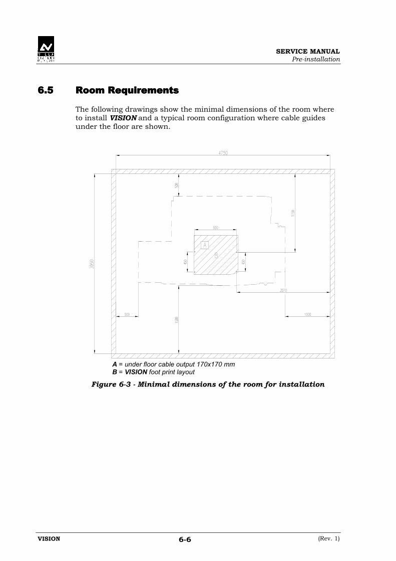
6.56.56.56.5 Room RequirementsRoom RequirementsRoom RequirementsRoom Requirements
The following drawings show the minimal dimensions of the room whereto install VISION and a typical room configuration where cable guidesunder the floor are shown.
A = under floor cable output 170x170 mm B = VISION foot print layout
Figure 6-3 - Minimal dimensions of the room for installation

SERVICE MANUALPre-installation
(Rev. 1) VISION6-7
Figure 6-4 - Setting of a "typical" installation room

SERVICE MANUALPre-installation
VISION (Rev. 1)6-8
THIS PAGE IS INTENTIONALLY LEFT BLANK

SERVICE MANUALInstallation
(Rev. 1) VISION7-1
7.7.7.7. INSTALLATIONINSTALLATIONINSTALLATIONINSTALLATION
WARNING:While installing the unit, follow carefully safety precautions formechanical and electrical hazards:• wear protective clothes (shoes, gloves, glasses, when necessary)• do not lift excessive weight• take care to work in safety conditions• access electrical components only after having made yourself sure
that line voltage is disconnected.
The unit is shipped pre-assembled in sub-assemblies.Mechanical installation consists of putting together these sub-assemblies.Chains regulation, ball bearing setting, brakes adjustment and tighteningtorque is adjusted in manufacturing before delivery.
Do not change original settings, because besides being useless, itcan generate malfunctions.
SERVICE MANUALInstallation
VISION (Rev. 2)7-2
7.17.17.17.1 Support base positioningSupport base positioningSupport base positioningSupport base positioning
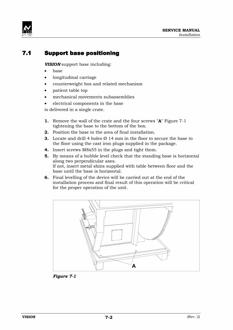
VISION support base including:• base• longitudinal carriage• counterweight box and related mechanism• patient table top• mechanical movements subassemblies• electrical components in the baseis delivered in a single crate.
1. Remove the wall of the crate and the four screws "A" Figure 7-1tightening the base to the bottom of the box.
2. Position the base in the area of final installation.3. Locate and drill 4 holes Ø 14 mm in the floor to secure the base to
the floor using the cast iron plugs supplied in the package.4. Insert screws M8x55 in the plugs and tight them.5. By means of a bubble level check that the standing base is horizontal
along two perpendicular axes.If not, insert metal shins supplied with table between floor and thebase until the base is horizontal.
6. Final levelling of the device will be carried out at the end of theinstallation process and final result of this operation will be criticalfor the proper operation of the unit.
A
Figure 7-1

SERVICE MANUALInstallation
(Rev. 2) VISION7-3
7.27.27.27.2 Spot film device carriage assemblingSpot film device carriage assemblingSpot film device carriage assemblingSpot film device carriage assembling
1. Remove the stopper / bumper assy of the longitudinal movement "A"Figure 7-2 (rear part of the table) located on the SFD / longitudinalcarriage.
A
Figure 7-2
2. Remove X-ray tube support plate "C" Figure 7-11 by removing the 4screws "F" Figure 7-11 that are not marked in red.
3. From the rear of the unit, insert guides "B" Figure 7-3 of the SFDcarriage between ball bearings "C" Figure 7-3 of the longitudinalcarriage.Be careful not to damage the guides or the ball bearing in this step.No adjustment of the ball bearing is necessary because setting hasalready been carried out during manufacturing
4. Put back the stopper / bumper assy in its original position.
B
C
Figure 7-3

SERVICE MANUALInstallation
VISION (Rev. 2)7-4
7.37.37.37.3 Spot film device assemblySpot film device assemblySpot film device assemblySpot film device assembly
1. Remove safety screw "A" Figure 7-4 in the front side of the side rail ofthe SFD.
D
A
Figure 7-4
2. Check that the rear part of the supporting bracket of the SFD,present on the scanning group, is positioned to allow an easyinsertion of the SFD.
3. Mount the SFD in the supporting brackets inserting guides "B"Figure 7-5 between ball bearings "C" Figure 7-5 present inside thebrackets.While inserting the SFD in the brackets, pull the lockinghandle positioned on the lower bracket when the SFD gets intouch with it.Take care to prevent damaging the guides of the ball bearing duringthis operation.No adjustment of ball bearings is necessary, because it has alreadybeen done in manufacturing before delivery.
B
C
Figure 7-5

SERVICE MANUALInstallation
(Rev. 2) VISION7-5
4. Put back safety screw "A" Figure 7-4 on the SFD guide.5. Check that the locking handle of the SFD, positioned in the lower
bracket, locks the SFD when positioned in the "out" of field or in the"in" field positions, entering locking holes "D" Figure 7-4 in the lowerguide.
6. Check that the handle can be extracted easily from the holes.7. Check that the microswitch on the rear of the SFD is be pressed
when the SFD is "in" field position.

SERVICE MANUALInstallation
VISION (Rev. 2)7-6
7.47.47.47.4 Image intensifier assemblingImage intensifier assemblingImage intensifier assemblingImage intensifier assembling
Mount the image intensifier on the support plate and screw the plate/I.I.sub-assembly on the front plate of the SFD as in Figure 7-6, usingsupplied screws.
NOTE:Position the I.I. so that cables exit towards the rear part of the SFD.
Figure 7-6
Complete assembling of the SFD accessories:• lead apron, inserting it in the trail in the lower part of the SFD• the cough protection, screwing it to the upper edge of the SFD cover• the compressor, fitting it in the slot of the compressor support,
positioned in the rear part of the SFD.
Once all accessories of the SFD are in place, balancing of the SFD can becarried out.This operation is carried out by inserting the lead and iron plates in thecounterweight box "A" Figure 7-7, in the rear part of the SFD carriage.Balancing is reached when the SFD maintains the position where it isleft, obviously with brakes not activated.
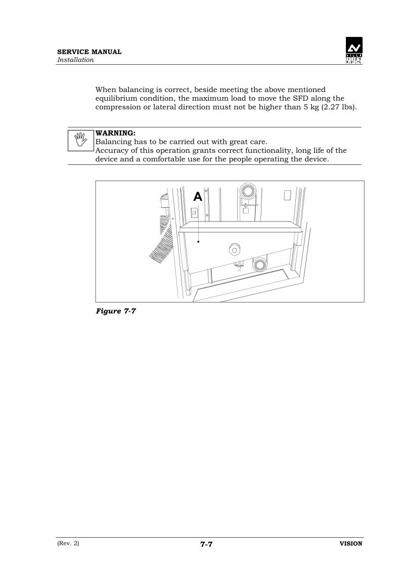
SERVICE MANUALInstallation
(Rev. 2) VISION7-7
When balancing is correct, beside meeting the above mentionedequilibrium condition, the maximum load to move the SFD along thecompression or lateral direction must not be higher than 5 kg (2.27 lbs).
WARNING:Balancing has to be carried out with great care.Accuracy of this operation grants correct functionality, long life of thedevice and a comfortable use for the people operating the device.
A
Figure 7-7

SERVICE MANUALInstallation
VISION (Rev. 2)7-8
7.57.57.57.5 Assembling of the corrugate hose and electricalAssembling of the corrugate hose and electricalAssembling of the corrugate hose and electricalAssembling of the corrugate hose and electricalconnectionsconnectionsconnectionsconnections
1. Mount one end "A" Figure 7-8 of the hose to the SFD. Mount thecentral part "B" Figure 7-9 of the hose to the SFD carriage, usingsupplied screws and support it by fixing it to the bracket positionedon the side of the table.
A
Figure 7-8
B
Figure 7-9
2. Fix the end of the cable guide to the base of the device in the forklodging, in the rear part of the base.
3. Connect plugs:- to the SFD following numbering- to the beam limiting device- to the electrical assy in the base of the device.
4. Connect three-phase power line to connectors R, S, T, N, andGround on the main connector X0.
5. Turn power on the device and check for proper phasing by activatingthe tilt command on the SFD keypad.If the movement disagrees with the symbol on the joystick, reversephases.

SERVICE MANUALInstallation
(Rev. 1) VISION7-9
7.67.67.67.6 X-ray tube and beam limiting device assemblingX-ray tube and beam limiting device assemblingX-ray tube and beam limiting device assemblingX-ray tube and beam limiting device assembling
1. Remove the screw fixing the frontal counterweight "A" Figure 7-10.
A
Figure 7-10
2. Push the SFD carriage towards the extreme position of foot side andtilt the table until the vertical position is reached.
3. Assembly the X-ray tube and the beam-limiting device on the supportplate before screwing it to the SFD carriage.
4. Mount X-ray tube on the support plate "B" Figure 7-11.5. Mount the beam-limiting device on the support already fixed on plate
"C" Figure 7-11.6. Now assemble the sub-assy composed of:
- X-ray tube- beam limiting support- beam limiting device- support plate and counter plateon the SFD carriage as shown in Figure 7-11.
NOTE:Support plates for X-ray tube and beam limiting device are pre-set duringfinal testing in manufacturing so no further intervention is needed.
In case it is deemed necessary to correct centering of beam limitingdevice and X-ray tube with respect to SFD or image intensifier, proceedas follows:
• Beam limiting device centring:Move the centre of the beam limiting device, releasing the 4 screws,blocking it on the support.

SERVICE MANUALInstallation
VISION (Rev. 2)7-10
• X-ray tube centring:As said above, the X-ray support plate is pre-set in manufacturing,but in case the position has to be corrected act on the 4 bolts "E"Figure 7-11 of the counter plate and, acting on the eccentric "D"Figure 7-11, modify the position of the X-ray tube.Connect connectors and wires to the connection positioned on theside of the X-ray tube-beam limiting device subassembly.
B
C
D
F
E
Figure 7-11
SERVICE MANUALInstallation
(Rev. 2) VISION7-11
7.77.77.77.7 Balancing and final checksBalancing and final checksBalancing and final checksBalancing and final checks
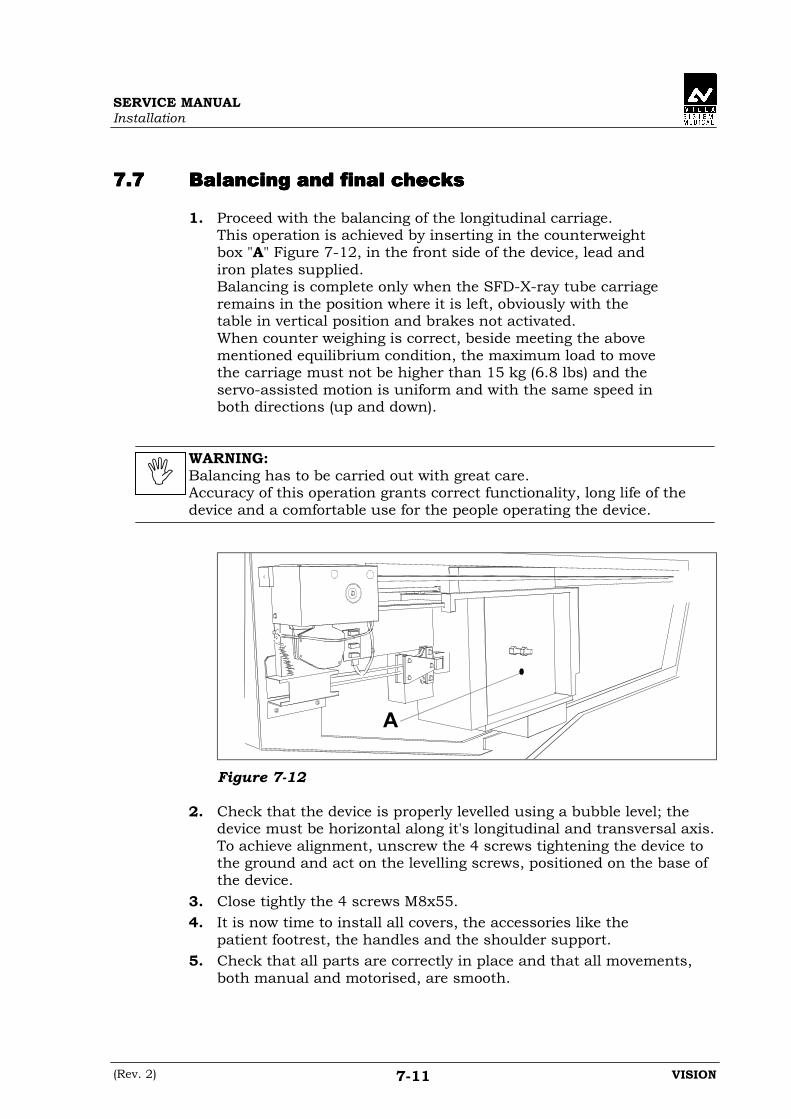
1. Proceed with the balancing of the longitudinal carriage.This operation is achieved by inserting in the counterweightbox "A" Figure 7-12, in the front side of the device, lead andiron plates supplied.Balancing is complete only when the SFD-X-ray tube carriageremains in the position where it is left, obviously with thetable in vertical position and brakes not activated.When counter weighing is correct, beside meeting the abovementioned equilibrium condition, the maximum load to movethe carriage must not be higher than 15 kg (6.8 lbs) and theservo-assisted motion is uniform and with the same speed inboth directions (up and down).
WARNING:Balancing has to be carried out with great care.Accuracy of this operation grants correct functionality, long life of thedevice and a comfortable use for the people operating the device.
A
Figure 7-12
2. Check that the device is properly levelled using a bubble level; thedevice must be horizontal along it's longitudinal and transversal axis.To achieve alignment, unscrew the 4 screws tightening the device tothe ground and act on the levelling screws, positioned on the base ofthe device.
3. Close tightly the 4 screws M8x55.4. It is now time to install all covers, the accessories like the
patient footrest, the handles and the shoulder support.5. Check that all parts are correctly in place and that all movements,
both manual and motorised, are smooth.

SERVICE MANUALInstallation
VISION (Rev. 1)7-12
THIS PAGE IS INTENTIONALLY LEFT BLANK
SERVICE MANUALUndertable Potter Bucky (optional)
(Rev. 1) VISION8-1
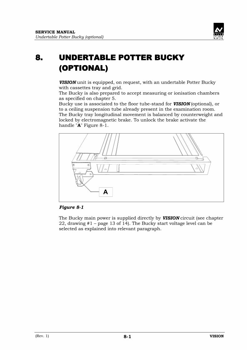
8.8.8.8. UNDERTABLE POTTER BUCKYUNDERTABLE POTTER BUCKYUNDERTABLE POTTER BUCKYUNDERTABLE POTTER BUCKY(OPTIONAL)(OPTIONAL)(OPTIONAL)(OPTIONAL)
VISION unit is equipped, on request, with an undertable Potter Buckywith cassettes tray and grid.The Bucky is also prepared to accept measuring or ionisation chambersas specified on chapter 5.Bucky use is associated to the floor tube-stand for VISION (optional), orto a ceiling suspension tube already present in the examination room.The Bucky tray longitudinal movement is balanced by counterweight andlocked by electromagnetic brake. To unlock the brake activate thehandle "A" Figure 8-1.
A
Figure 8-1
The Bucky main power is supplied directly by VISION circuit (see chapter22, drawing #1 – page 13 of 14). The Bucky start voltage level can beselected as explained into relevant paragraph.

SERVICE MANUALUndertable Potter Bucky (otional)
VISION (Rev. 3)8-2
8.18.18.18.1 Bucky start voltage settingBucky start voltage settingBucky start voltage settingBucky start voltage setting
The Bucky control PCB is designed in order to accept three differentBucky start voltages depending on the generator connected. Thesevoltages must be connected to the X0 general terminal board, to pins 49and 50.The voltages allowed are: 24Vdc, 120Vac and 230Vac.The voltage selection is made by jumpers present on Potter-Bucky board(A14) and reference is listed below:
Voltage Jumper X4 Jumper X5
24 Vdc (*) A - C120 Vac A - B A - B230 Vac A - B A - C
(*) Factory default setting
To identify the jumpers position see Figure 8-2.
Figure 8-2
NOTE:In case the voltage selected is 24Vdc the positive must be connected toX0-49 and negative to X0-50.

SERVICE MANUALUndertable Potter Bucky (optional)
(Rev. 3) VISION8-3
8.28.28.28.2 Sensing Cassettes Tray installationSensing Cassettes Tray installationSensing Cassettes Tray installationSensing Cassettes Tray installation
The standard Bucky cassettes tray is auto centering in transversal way.To maintain the cassette in vertical position a magnetic support block isused.
The Bucky is also predisposed to accept sensing cassettes traymanufactured by POERSCH and LIEBEL. To adapt the Bucky to usethese kind of cassettes tray it is necessary to use the sensing tray kitp/n 7120520500 following the instruction given below:
1. Take out the block "A" Figure 8-3 mounted on frontal lower part ofthe Bucky. Replace with the washers and the TS M4x5 screwsprovided in the sensing tray kit. These screws will work as stoppingdevice.
A
Figure 8-3
2. The Bucky carriage rear plate is predisposed to fix the three partsnecessary to complete the installation:• lateral sensing closing device "A" (Figure 8-4 in the next page)• shifting connector "B" (Figure 8-4 in the next page)• general signals connector "A" (Figure 8-5 in the next page).The double holes for cable routing and fixing of "A" and "B" items(Figure 8-4 in next page) are pre-set in order to accept theaccessories proper of the cassette tray used.
3. The VISION is predisposed with a 8 wires shielded cable to connectthe sensing cassettes tray. This cable is positioned in such a way tohave one terminal in the general signals connector area (Figure 8-5 inthe next page) and the other in the table base. Identify which wiresmust be used and connect them following drawing supplied bysensing cassettes tray manufacturer.
4. Two plastic adapter are supplied with VISION to optimise thecassettes sensing tray installation into the Bucky. Stick them on thelateral side of the tray to reduce the clearance present between trayand Bucky guide.

SERVICE MANUALUndertable Potter Bucky (otional)
VISION (Rev. 1)8-4
A
BUPPER VIEW
REAR VIEW
Figure 8-4
A
Figure 8-5

SERVICE MANUALOperating logic of the table
(Rev. 1) VISION9-1
9.9.9.9. OPERATING LOGIC OF THE TABLEOPERATING LOGIC OF THE TABLEOPERATING LOGIC OF THE TABLEOPERATING LOGIC OF THE TABLE
The electronic control logic of VISION consists of:• one "CONTROL PANEL""CONTROL PANEL""CONTROL PANEL""CONTROL PANEL" circuit board containing all the electronic
components necessary for its operation, the control keys, and thecorresponding indicator LEDs
• one "CPU""CPU""CPU""CPU" circuit board containing all the electronic componentsnecessary for its operation, the output drivers and the input ports.On this circuit board there are 2 separate microprocessors.
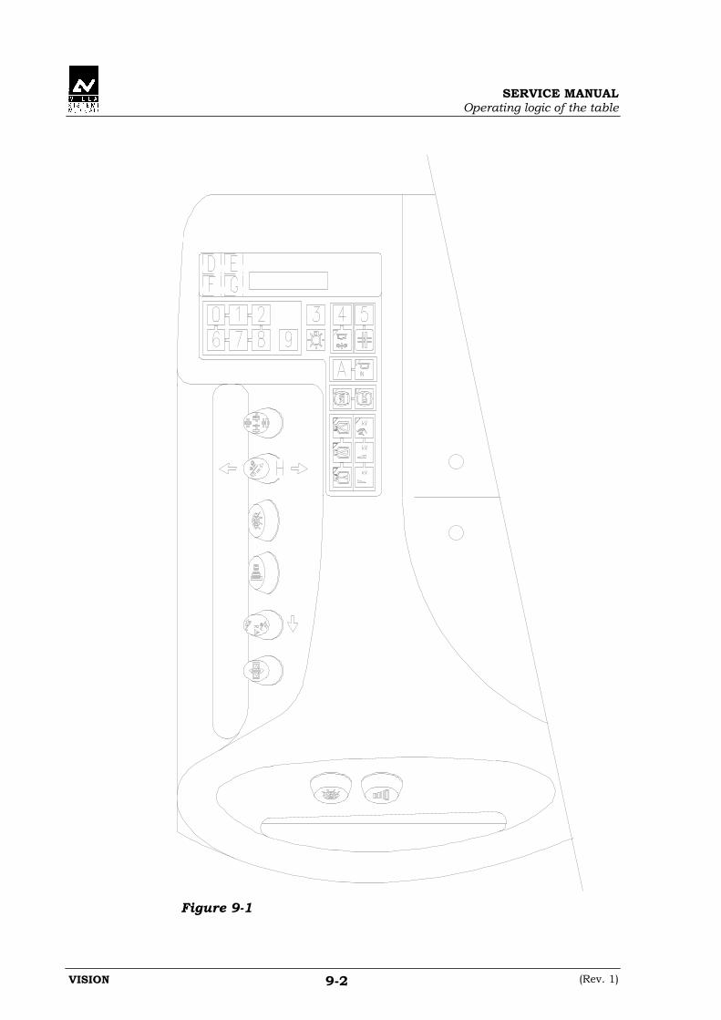
The first microprocessor, a Motorola type MC68332, is equipped withtwo 27C1001 128Kx8 EPROMs and has the function of controllingand managing all the table functions.These 2 EPROMs contain the operating program.The program version is identified by a revision number on theEPROM labels.The program contains its date and time of compilation, which identifyit unequivocally.To display this information, proceed as follows:1. Turn off the system2. Remove the SFD cover3. Put switch 2 of dip switch group Q16 on4. Turn on the system5. Press the D key (Figure 9-1 in next page) for 5 sec.
When this time has elapsed, the display will show:- 002, page number used for entering the passwords.- 000, waiting for the password to be entered
6. Press the E key (Figure 9-1).The display will show the compilation DATE and TIME of theSoftware version in use:
Version X.X
DD.MM.YY HH.MM
7. Turn off the system8. Restore dip switch 2 of dip switch group Q16 to off position9. Re-install SFD cover10. Turn on the system. The table reverts to its standard operating
mode.
The second microprocessor, an ATMEL 89C2051, has the function of"Supervisor" of the correct operation of the table, providing a backupto the first microprocessor in accordance with the Single Fault (SF)principle.This operating logic is described in detail in chapter 12 "Single FaultOperating Logic"
• a "DRIVER""DRIVER""DRIVER""DRIVER" board board board board, which has the function of driving the principalmotors of the serial changer (cassette tray and shutters), modulatingthe signal by means of dedicated electronic components.
SERVICE MANUALOperating logic of the table
VISION (Rev. 1)9-2
Figure 9-1
SERVICE MANUALOperating logic of the table
(Rev. 1) VISION9-3
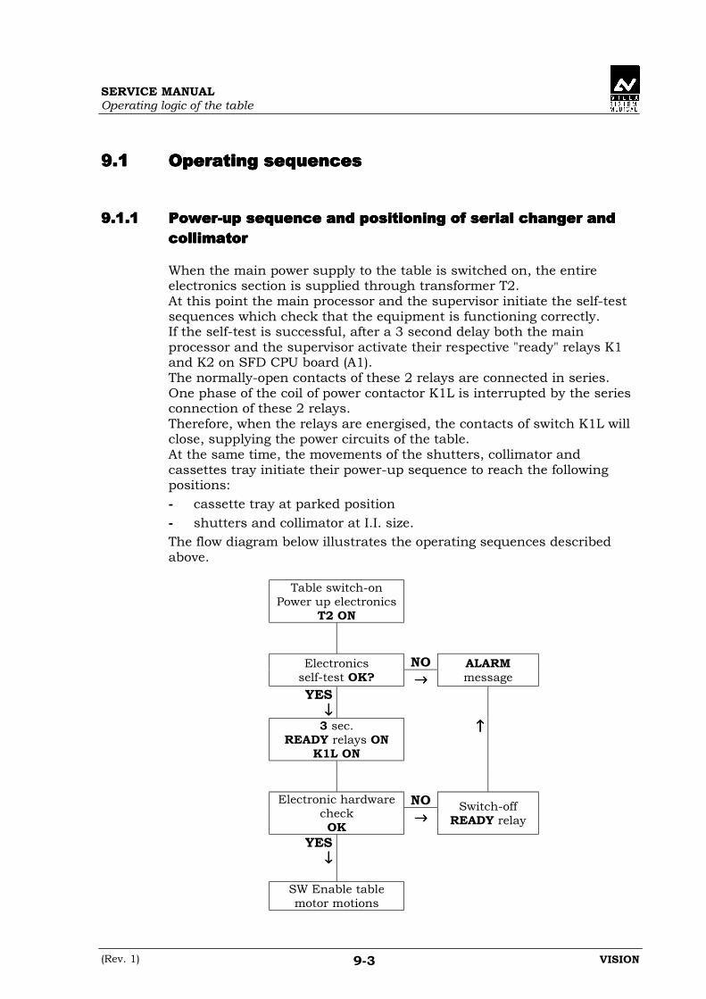
9.19.19.19.1 Operating sequencesOperating sequencesOperating sequencesOperating sequences
9.1.19.1.19.1.19.1.1 Power-up sequence and positioning of serial changer andPower-up sequence and positioning of serial changer andPower-up sequence and positioning of serial changer andPower-up sequence and positioning of serial changer andcollimatorcollimatorcollimatorcollimator
When the main power supply to the table is switched on, the entireelectronics section is supplied through transformer T2.At this point the main processor and the supervisor initiate the self-testsequences which check that the equipment is functioning correctly.If the self-test is successful, after a 3 second delay both the mainprocessor and the supervisor activate their respective "ready" relays K1and K2 on SFD CPU board (A1).The normally-open contacts of these 2 relays are connected in series.One phase of the coil of power contactor K1L is interrupted by the seriesconnection of these 2 relays.Therefore, when the relays are energised, the contacts of switch K1L willclose, supplying the power circuits of the table.At the same time, the movements of the shutters, collimator andcassettes tray initiate their power-up sequence to reach the followingpositions:- cassette tray at parked position- shutters and collimator at I.I. size.The flow diagram below illustrates the operating sequences describedabove.
Table switch-onPower up electronics
T2 ON
NOElectronicsself-test OK? →→→→
ALARMmessage
YES↓↓↓↓
3 sec.READY relays ON
K1L ON
↑↑↑↑
NOElectronic hardwarecheckOK
→→→→Switch-off
READY relay
YES↓↓↓↓
SW Enable tablemotor motions
SERVICE MANUALOperating logic of the table
VISION (Rev. 1)9-4
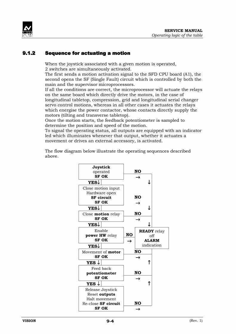
9.1.29.1.29.1.29.1.2 Sequence for actuating a motionSequence for actuating a motionSequence for actuating a motionSequence for actuating a motion
When the joystick associated with a given motion is operated,2 switches are simultaneously activated.The first sends a motion activation signal to the SFD CPU board (A1), thesecond opens the SF (Single Fault) circuit which is controlled by both themain and the supervisor microprocessors.If all the conditions are correct, the microprocessor will actuate the relayson the same board which directly drive the motors, in the case oflongitudinal tabletop, compression, grid and longitudinal serial changerservo control motions, whereas in all other cases it actuates the relayswhich energise the power contactor, whose contacts directly supply themotors (tilting and transverse tabletop).Once the motion starts, the feedback potentiometer is sampled todetermine the position and speed of the motion.To signal the operating status, all outputs are equipped with an indicatorled which illuminates whenever that output, whether it actuates amovement or drives an external accessory, is activated.
The flow diagram below illustrate the operating sequences describedabove.
NOJoystickoperatedSF OK →→→→
YES↓↓↓↓ ↓↓↓↓
NO
Close motion inputHardware open
SF circuitSF OK →→→→
YES↓↓↓↓ ↓↓↓↓NOClose motion relay
SF OK →→→→YES↓↓↓↓ ↓↓↓↓
NOEnable
power HW relaySF OK →→→→
YES↓↓↓↓
READY relayoff
ALARMindication
NOMovement of motorSF OK →→→→
YES ↓↓↓↓ ↑↑↑↑
NOFeed back
potentiometerSF OK →→→→
YES ↓↓↓↓ ↑↑↑↑
NO
Release JoystickReset outputsHalt movement
Re-close SF circuitSF OK →→→→

SERVICE MANUALOperating logic of the table
(Rev. 1) VISION9-5
9.29.29.29.2 Error conditionsError conditionsError conditionsError conditions
During the operation of the equipment, there are 3 different types of errorconditions which can occur:• status error• functional error• power circuits error
These 3 different types of errors are handled as follows.
9.2.19.2.19.2.19.2.1 Generation of a status alarmGeneration of a status alarmGeneration of a status alarmGeneration of a status alarm
During the operation of the system, an anomaly affecting the table or oneof the connected accessories may be detected.If this malfunction does not compromise the operation of the system(Example: the generator is not "ready" within the established time-out),certain motions will by disabled by the SW and the corresponding alarmwill blink on the display, accompanied by an intermittent buzzer.To reset the alarm and re-enable all the movements, shift the table-tiltingjoystick (Figure 9-1) twice in the reset ("R") direction.The first joystick movement silences the buzzer, the second resets thealarm and re-enable normal operation.
The flow diagram below illustrate the operating sequences describedabove.
Error type:resettable
←←←←Alarm ondisplay
blinking
Reset Joystick:-1st beep OFF-2nd alarm OFF
↑↑↑↑
NOCause of errorremoved →→→→
YES ↓↓↓↓Re-enable
normal systemoperation

SERVICE MANUALOperating logic of the table
VISION (Rev. 1)9-6
9.2.29.2.29.2.29.2.2 Generation of a functional alarm.Generation of a functional alarm.Generation of a functional alarm.Generation of a functional alarm.
If the microprocessor detects an anomaly, generated by the SF circuit orby other components interacting with the microprocessor, which couldseriously compromise the operation of the table, the READY relays arede-energised and a blinking alarm indication appears on the display.This condition cannot be reset, because it constitutes a "serious"malfunction.It will therefore be necessary to diagnose the cause of the problem.The equipment must be switched off to reset the alarm and re-enable themotions.
The flow diagram below illustrate the operating sequences describedabove.
Error type:- Single Fault- Component
OpenREADY relay
BlinkingNON resettable
alarm ondisplay
Switch offthe unit
Seek fault
SERVICE MANUALOperating logic of the table
(Rev. 1) VISION9-7
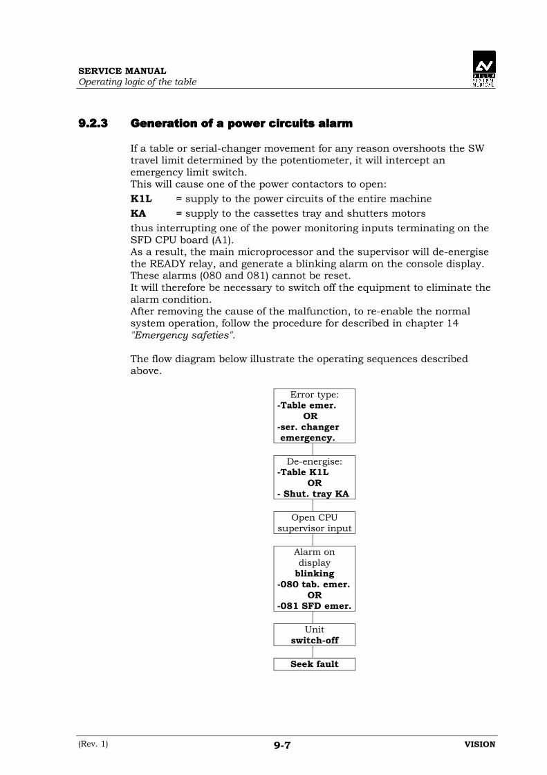
9.2.39.2.39.2.39.2.3 Generation of a power circuits alarmGeneration of a power circuits alarmGeneration of a power circuits alarmGeneration of a power circuits alarm
If a table or serial-changer movement for any reason overshoots the SWtravel limit determined by the potentiometer, it will intercept anemergency limit switch.This will cause one of the power contactors to open:K1L = supply to the power circuits of the entire machineKA = supply to the cassettes tray and shutters motorsthus interrupting one of the power monitoring inputs terminating on theSFD CPU board (A1).As a result, the main microprocessor and the supervisor will de-energisethe READY relay, and generate a blinking alarm on the console display.These alarms (080 and 081) cannot be reset.It will therefore be necessary to switch off the equipment to eliminate thealarm condition.After removing the cause of the malfunction, to re-enable the normalsystem operation, follow the procedure for described in chapter 14"Emergency safeties".
The flow diagram below illustrate the operating sequences describedabove.
Error type:-Table emer.
OR-ser. changer emergency.
De-energise:-Table K1L
OR- Shut. tray KA
Open CPUsupervisor input
Alarm ondisplay
blinking-080 tab. emer.
OR-081 SFD emer.
Unitswitch-off
Seek fault

SERVICE MANUALOperating logic of the table
VISION (Rev. 1)9-8
THIS PAGE IS INTENTIONALLY LEFT BLANK

SERVICE MANUALConnecting the I/O interface
(Rev. 1) VISION10-1
10.10.10.10. CONNECTING THE I/O INTERFACECONNECTING THE I/O INTERFACECONNECTING THE I/O INTERFACECONNECTING THE I/O INTERFACE
All the input and output signals to and from accessories such as:generator, TV chain etc. are connected to the SFD CPU board (A1) and togeneral terminal board X0.The hardware characteristics of these signals are set out below:
A1connect. X0 Type Description Hardware characteristics Electrical
characteristics// 1-2 Contact Room light Free relay contact max 220 V a.c. 2 A
X7-20 3 OUT/IN Common 0 Vs Polarisation at 0 Vs NAX7-21 4 OUT 0 Vs Fluoroscopy Transistor open collector NPN max 100 mA d.c.X7-22 5 OUT 0 Vs Preparation Transistor open collector NPN max 100 mA d.c.
X7-23 6 OUT 0 Vs Digitalpreparation
Transistor open collector NPN max 100 mA d.c.
X7-24 7 OUT 0 Vs Exposure switch2nd step
Transistor open collector NPN max 100 mA d.c.
X7-25 8 OUT 0 Vs Exposure Transistor open collector NPN max 100 mA d.c.
X7-26 9 OUT 0 Vs X-ray ON withoutrequest
Transistor open collector NPN max 100 mA d.c.
X7-27 10 OUT 0 Vs Fluoro kV-mAman./auto
Transistor open collector NPN max 100 mA d.c.
X7-28 11 OUT Common 0 V forX0-12
0 V dc for analog manual kV max 5 mA d.c.
X7-29 12 OUT Analog formanual kV
Analog output from 1.8 to6.5 V dc
max 5 mA d.c.
X7-31 14 OUT I.I. max Optomos out polaris. in X0-17 max 24 Vac/70Vdc- 70 mA
X7-32 15 OUT I.I. med Optomos out polaris. in X0-17 max 24 Vac/70Vdc- 70 mA
X7-33 16 OUT I.I. min Optomos out polaris. in X0-17 max 24 Vac/70Vdc- 70 mA
X7-34 17 IN Common for I.I.circuit
Optomos common input max 24 Vac/70Vdc- 70 mA
X7-35 18 OUT Monitor imagevertical reverse
Optomos out polaris. in X0-20 max 24 Vac/70Vdc- 70 mA
X7-36 19 OUT Monitor imagehorizont. reverse
Optomos out polaris. in X0-20 max 24 Vac/70Vdc- 70 mA
X7-37 20 IN Common forimage reverse
Optomos common input max 24 Vac/70Vdc- 70 mA
X15-2 21 IN Generator ready Input NPN active at 0 Vs max 10 mA d.c.X15-3 22 IN X-ray on Input NPN active at 0 Vs max 10 mA d.c.
X15-7 23 IN Serial changerworking station
Input NPN active at 0 Vs max 10 mA d.c.
X15-8 24 IN Digital workingstation
Input NPN active at 0 Vs max 10 mA d.c.
X69-12X69-13
25-26 OUT Table at 0° tilting Free relay contact max 15 Vac –500 mA
X69-14X69-15
27-28 OUT Table at 90°tilting
Free relay contact max 15 Vac –500 mA
X15-13 41 OUT 0 Vs Manual fluoro kVup
Transistor open collector NPN max 100 mA d.c.
X15-14 42 OUT 0 Vs Manual fluoro kVdown
Transistor open collector NPN max 100 mA d.c.
X15-15 43 OUT 0 Vs Motion detection Transistor open collector NPN max 100 mA d.c.

SERVICE MANUALConnecting the I/O interface
VISION (Rev. 1)10-2
The accessory functions on terminal block X0 are detailed below.
A1connect. X0 Type Description Hardware characteristics Electrical
characteristics
X15-5 29 IN Inhibit insidetabletop motion
Input NPN active at 0 Vs max 10 mA d.c.
X15-4 33 INInhibit foot endservo controlmotion
Input NPN active at 0 Vs max 10 mA d.c.
NA 35-36 Contact Emergencybutton
Button contact max 24 V ac – 2 A
NA 37-38 OUT
Seriesinterruption ofpower contactorK1L coil
Coil of contactor K1L max 24 Vac –500 mA
NA 39-40 OUT 24 V dc powersupply for loads
24 V dc (39 negative –40 positive)
max 0.5 A
WARNING:The above signals are all referred to ground.Therefore, the accessories connected to them must not have anyaccessible electrical parts.

SERVICE MANUALConnecting the I/O interface
(Rev. 2) VISION10-3
10.110.110.110.1 Optional Fluoro Foot-Switch connectionOptional Fluoro Foot-Switch connectionOptional Fluoro Foot-Switch connectionOptional Fluoro Foot-Switch connection
If required by customer, the VISION is predisposed to accept anadditional fluoro foot-switch connected to the Interconnection board (A6).The characteristics and connection of the foot-switch are detailed below:
X76 Type Description Electricalcharacteristics
1 Common 0V2
Contact NOFluoro input
Min 10 mA dc, 24 Vdc
45
Contact NC Single faults series Min 10 mA dc, 24 Vdc
NOTE:The foot-switch must be equipped with 2 switches or 1 switches - 2 ways(1NC + 1NO) with contemporary switching.
The relevant layout and drawings are present in chapter 22, drawings#1 (page 10 of 14) and #9.

SERVICE MANUALConnecting the I/O interface
VISION (Rev. 2)10-4
10.210.210.210.2 Input / Output operating logicInput / Output operating logicInput / Output operating logicInput / Output operating logic
The input and output signals are activated and resetted according tocertain logic sequences.The table below describes their operation.It also describes the impact of the accessory functions on the operation ofthe equipment.
X0 Description Activation signal conditions Reset-signalconditions
1-2 Room light ON switch operated OFF switch operated
4Fluoroscopy - Serial changer in centre (Switch S10 on) AND
- Potter-Bucky in park (Switch S62 on) AND- Cassettes tray parked AND- Control pressed
Any one of theactivated-signalconditions absent.
5
Preparation - Serial changer in centre (Switch S10 on) AND- Potter-Bucky in park (Switch S62 on) AND- Cassette present and sub-division selected (only for serial changer mode and not for DSI mode ) AND- Control pressed (1st step)
Control released OR"X-ray ON" input OFFafter an exposure
6DigitalPreparation
- Serial changer in centre (Switch S10 active) AND- Potter-Bucky in park (Switch S62 on) AND- Digital selected AND- Control pressed
Control released
7
Exposureswitch 2ndstep
- Serial changer in centre (Switch S10 active) AND- Potter-Bucky in park (Switch S62 on) AND- Preparation active AND- Serial changer shutters in position (not for DSI mode) AND- Cassettes tray in position (not for DSI mode) AND- Collimator in position AND- Control pressed (2nd step)
Control released ORone of the conditionsabsent
8Radiography - "Generator ready " input activated AND
- Grid start delay elapsed (not for DSI mode)
Control released OR"X-ray ON" input OFFafter an exposure
9
"X-ray ON"active withoutrequest
Exposure OFFNote: The output is activated during normal
operation. It is reset in an alarm condition.This operating logic is inverted relative to allthe other OUTPUTS
With "digital" or"serial changer"working stationselected and "X-rayON" active withoutfluoroscopy orexposure request
10ManualkV/mA
- Button pressed:• button led ON• output OFF
- Button pressed:• button led OFF• output ON
12Analogmanualfluoroscopy kVV ref
- manual kV control operated- increase voltage with kV+ button- reduce voltage with kV- buttonNote: voltage range +1.8 - +6.5 V dc.
- automatic kV control operated OR- buttons not pressed
14
I.I. max. - Button pressed:• button led ON• output ON
- I.I. med. button OR I.I. min button pressed:• button led OFF• output OFF

SERVICE MANUALConnecting the I/O interface
(Rev. 2) VISION10-5
X0 Description Activation-signal conditions Reset-signalconditions
15
I.I. med. - Button control:• button led ON• output ON
- I.I. max. button OR I.I. min. button pressed:• button led OFF• output OFF
16
I.I. min. - Control on button:• button led ON• output ON
- I.I. med. button OR I.I. max. button pressed:• button led OFF• output OFF
18Monitor imageverticalreverse
- Button pressed:• button led ON• output ON (with cell 237=0)
- Button pressed:• button led OFF• output OFF
19Monitor imagehorizontalreverse
- Button pressed:• button led ON• output ON (with cell 236=0)
- Button pressed:• button led OFF• output OFF
21 Generatorready
Generator ready for exposure Generator preparationnot complete
22X-ray ON - Exposure active in generator (kV at 75% of
nominal value)- Fluoroscopy active
End of exposure
23Serial changer "Serial changer" working station selected "Serial changer"
working stationdeselected
24 Digital "Digital" working station selected "Digital" workingstation deselected
25-26 Tilting at 0° Relay contact closed with table tilting between0 and +10°
Table in any otherposition
27-28 Tilting at 90° Relay contact closed with table tilting between +80and +90°
Table in any otherposition
29Inhibit insidetabletopmotion
Jumper on terminal block X0 29-30 open Jumper X0 29-30closed
33Inhibit foot-endservomotormotion
Jumper on terminal block X0 33-34 open Jumper X0 33-34closed
41Manual kVincrease
- manual kV control activated AND- kV+ button pressed
- automatic kV control activated OR- kV+ button not pressed
42Manual kVdecrease
- manual kV control activated AND- kV- button pressed
- automatic kV control activated OR- kV- button not pressed
43
Motiondetection
- foot side tabletop control activated OR- head side tabletop control activated OR- inside tabletop control activated OR- outside tabletop control activated OR- head side servomotor control activated OR- foot side servomotor control activated
All tabletop andservomotor controlsinactive

SERVICE MANUALConnecting the I/O interface
VISION (Rev. 2)10-6
THIS PAGE IS INTENTIONALLY LEFT BLANK

SERVICE MANUALParameter set-up procedure
(Rev. 1) VISION11-1
11.11.11.11. PARAMETER SET-UP PROCEDUREPARAMETER SET-UP PROCEDUREPARAMETER SET-UP PROCEDUREPARAMETER SET-UP PROCEDURE
WARNING:This page contains the passwords for accessing the memory of thesystem. In the remainder of the chapter, only the correspondingreferences (Rif.1, Rif.2 and Rif.3) will be quoted.The passwords may ONLY be used by technicians authorised by VILLASISTEMI MEDICALI S.p.a..
REFERENCE CODE PRESENT
IN THE MANUAL
PASSWORD TO USE ON THE
CONTROL PANEL
Ref. 1 488591
Ref. 2 48859284
Ref. 3 229879
SERVICE MANUALParameter set-up procedure
VISION (Rev. 1)11-2
All the data for the configuration, operation and adjustment of VISIONsystem are stored on an EEPROM, including a checksum which isupdated whenever the data is changed.At power-up, the data is copied into RAM, the checksum is recalculatedand compared with the value stored in the EEPROM. If the twochecksums do not match, alarm 090 is generated.When the equipment is switched off, the data stored in RAM is lost,whereas the values in the EEPROM are retained.The backup battery is used only for duplicating the EEPROMs asdescribed in paragraph 11.5.
The parameters contained in the EEPROM are subdivided into different"groups".Each of these groups can contain up to 99 positions or "cells".Any given memory cell is therefore identified by the following 3 digits:
0 00↓↓↓↓ ↓↓↓↓
Group Number Cell position
To obtain read-only access to the data contained in the cells, simplyplace the switch corresponding to its group (of DIP-switch Q16 on theSFD CPU board A1) in the ON position.To be able to modify, i.e. write new data in the cells, it is necessary toenter a password, in addition to enabling the corresponding switch.
The table below lists the sub-divisions of the data groups and theirfunctions, along with the corresponding switches and passwords.As already mentioned, the paragraphs and tables of this chapter indicatethe passwords using the references given in the previous page.
Switch Password Group Function
1 Ref. 1 100 Potentiometer adjustments2 Ref. 2 200 Installation parameters3 Ref. 1 300 PDI motor data
1 + 2 Ref. 3400500600
Unit dimensions and movements rangeCassettes tray travelsShutters travels
1 + 3 Ref. 1 700 EEPROM copying2 + 3 Ref. 3 800 Serial changer life test
NOTE:The procedures explained in the next pages make often reference toFigure 11-9 at the end of this chapter. To easily consult this figure,unfold page 11-59 in order to make it visible while reading other pages ofthe manual.

SERVICE MANUALParameter set-up procedure
(Rev. 1) VISION11-3
11.111.111.111.1 Accessing group 100: Potentiometer adjustmentsAccessing group 100: Potentiometer adjustmentsAccessing group 100: Potentiometer adjustmentsAccessing group 100: Potentiometer adjustments
As mentioned previously, the control of VISION motions is based on thefeedback received from the potentiometers.These potentiometers must therefore be adjusted, by storing the voltagesvalues of the minimum and maximum travel limits in the correspondingEEPROM cells.
To read the parameters stored in the group 100 cells, proceed as follows:
1. Turn off the equipment and place switch 1 (Dip-switch Q16 of SFDCPU board A1) in the ON position.
2. Turn on the equipment.The display will show:• the number of the group and the selected cell• the blinking value of the position which that motion must reach• the potentiometer reading at the current position after the ADC
conversion, expressed as a value between 0 and 4095.3. Use the G and E keys (Figure 11-9) to respectively increase and
decrease the number of the selected cell. As mentioned above, duringthis phase it is not possible to modify any parameters or actuate anymotions.
To edit these parameters and hence correct the potentiometeradjustments, proceed as follows:
4. Press the D key (Figure 11-9) for 5 sec.When this time has elapsed, the display will show:• 002, page number used for entering the passwords• 0000000, waiting for the password to be entered.
5. Press the F key (Figure 11-9).The blinking "*" symbol appears on the display, prompting forentering the password.
6. Enter the password for this data group (Ref. 1 pg. 11-1) using thenumber keys (Figure 11-9).This value will appear scrolling from right to left on the display.
7. Press the F key (Figure 11-9) to confirm.If the confirm key is not pressed within 15 sec. of entering the lastdigit, the blinking "*" symbol and the previously entered digitsdisappear from the display, and the unmodified value remains inmemory.If, instead, the confirm key is pressed within 15 sec., the blinkingC137 message appears, indicating that the password has permittedaccess to groups 100-300-700, depending on which ones have theirDIP-switch set to ON.
8. Hold down the D key (Figure 11-9) for 5 sec.The display reverts to showing the group 100 position previouslyabandoned to access page 002.

SERVICE MANUALParameter set-up procedure
VISION (Rev. 1)11-4
At this point, it is possible to edit the parameters in the cells of thisgroup.It is also possible to actuate movements for adjusting the potentiometers,using joystick H (Figure 11-9).In this program, only joystick H is enabled, and the motion which isactuated will depend on the selected cell.Shifting the joystick to the right (see Figure 11-9) actuates the selectedmotion in the direction of its maximum limit, and the potentiometervalue shown on the display increases.Shifting the joystick to the left actuates the selected motion in theopposite direction, towards its minimum limit, and the displayedpotentiometer value decreases.In this program, the speeds of the cassettes tray, collimator and shuttersmotions are automatically set by the calibration software and cannot bemodified.The anti-collision program is inactive during this adjustment program;therefore, always make sure there is no risk of collision before actuatingany motion.In addition, because the software travel limits are determined preciselyby this adjustment program, the motions will not be halted on reachingthese limits.If the selected motion overshoots its maximum travel, it will intercept theemergency switch, causing the equipment to halt.
The default travel limits for the motions are set up during the factorytesting of the equipment.The travel limits for the currently selected cell are shown on the display.These limits can be changed by editing the parameters in the cells ofgroup 400.The new values entered in the cells will determine the new travel limitsfor that motion.The above does not apply for cells 109-110-111-112.In fact, when these cells are selected, the displayed value, correspondingto the target collimation field size, is determined directly by the software.This number takes into account the setting of the SID potentiometer.

SERVICE MANUALParameter set-up procedure
(Rev. 1) VISION11-5
The following table gives the default travel limits for the different motions.
Cell Movement Movement direction Joystick Hdirection Travel limit
101 Tilting Trendelembourg Left -15.0102 Tilting Vertical Right 90.0103 Longitudinal t.top Foot side Left -400104 Longitudinal t.top Head side Right 600105 Transversal t.top Inside Left -100106 Transversal t.top Outside Right 100107 SID Minimum Left 520108 SID Maximum Right 785109 Collimator width Minimum Left 000110 Collimator width Maximum Right 318111 Collimator height Minimum Left 000112 Collimator height Maximum Right 314117 Shutters Both limits Both 0-375.8119 Cassettes tray Both limits Both 0-557.1
After having accessed group100, proceed as follows to adjust thepotentiometers referred to the movements listed above.
SERVICE MANUALParameter set-up procedure
VISION (Rev. 1)11-6
11.1.111.1.111.1.111.1.1 TILTING potentiometer settings (cell 101-102)TILTING potentiometer settings (cell 101-102)TILTING potentiometer settings (cell 101-102)TILTING potentiometer settings (cell 101-102)
Adjusting the minimum valueAdjusting the minimum valueAdjusting the minimum valueAdjusting the minimum value
1. Using the E and G keys (Figure 11-9), select cell 101 on the display
2. The blinking value –15.0 appears, corresponding to the target valuein degrees for performing the adjustment.
3. The potentiometer value after the ADC conversion is shown on thedisplay, expressed as a number between 0 and 4095.
4. Shift joystick H (Figure 11-9) to the left, actuating the tilting motiontowards trendelembourg.
5. The displayed potentiometer value should decrease.If this does not happen, it means that the 2 potentiometer terminalshave been connected the wrong way round.
6. Place a goniometer with spirit level on the patient support, and checkthat the minimum position, equivalent to a tilting angle of -15.0°, isreached.
7. Check that the potentiometer value is approximately 500, if it isn’t,disengage the gear and turn the potentiometer until the requiredvalue is obtained.
8. Press the F key (Figure 11-9) to confirm.If everything is correct, the blinking “Accepted” message will appearon the display for 2 seconds.
Adjusting the maximum valueAdjusting the maximum valueAdjusting the maximum valueAdjusting the maximum value
9. Use the G key to select cell 102.10. The display will show the blinking value 90, corresponding to the
target value in degrees for the adjustment, and the potentiometervalue after the ADC conversion, expressed as a number between0 and 4095.
11. Shift joystick H to the right, actuating the tilting motion towards thevertical direction.
12. The displayed potentiometer value should increase.
13. Place a goniometer with spirit level on the patient support, and checkthat the maximum position, equivalent to a tilting value of 90°, isreached.
14. Check that the potentiometer value is approximately 3300.
15. Press the F key to confirm.If everything is correct, the blinking “Accepted” message will appearfor 2 sec on the display.
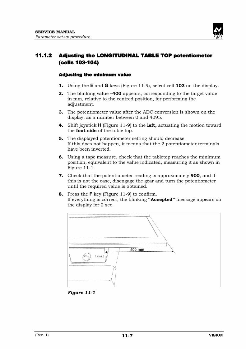
SERVICE MANUALParameter set-up procedure
(Rev. 1) VISION11-7
11.1.211.1.211.1.211.1.2 Adjusting the LONGITUDINAL TABLE TOP potentiometerAdjusting the LONGITUDINAL TABLE TOP potentiometerAdjusting the LONGITUDINAL TABLE TOP potentiometerAdjusting the LONGITUDINAL TABLE TOP potentiometer(cells 103-104)(cells 103-104)(cells 103-104)(cells 103-104)
Adjusting the minimum valueAdjusting the minimum valueAdjusting the minimum valueAdjusting the minimum value
1. Using the E and G keys (Figure 11-9), select cell 103 on the display.
2. The blinking value –400 appears, corresponding to the target valuein mm, relative to the centred position, for performing theadjustment.
3. The potentiometer value after the ADC conversion is shown on thedisplay, as a number between 0 and 4095.
4. Shift joystick H (Figure 11-9) to the left, actuating the motion towardthe foot side of the table top.
5. The displayed potentiometer setting should decrease.If this does not happen, it means that the 2 potentiometer terminalshave been inverted.
6. Using a tape measure, check that the tabletop reaches the minimumposition, equivalent to the value indicated, measuring it as shown inFigure 11-1.
7. Check that the potentiometer reading is approximately 900, and ifthis is not the case, disengage the gear and turn the potentiometeruntil the required value is obtained.
8. Press the F key (Figure 11-9) to confirm.If everything is correct, the blinking “Accepted” message appears onthe display for 2 sec.
Figure 11-1
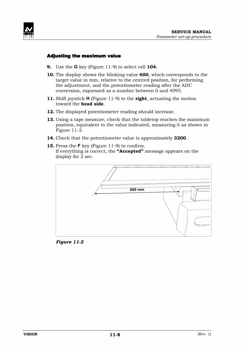
SERVICE MANUALParameter set-up procedure
VISION (Rev. 1)11-8
Adjusting the maximum valueAdjusting the maximum valueAdjusting the maximum valueAdjusting the maximum value
9. Use the G key (Figure 11-9) to select cell 104.10. The display shows the blinking value 600, which corresponds to the
target value in mm, relative to the centred position, for performingthe adjustment, and the potentiometer reading after the ADCconversion, expressed as a number between 0 and 4095.
11. Shift joystick H (Figure 11-9) to the right, actuating the motiontoward the head side.
12. The displayed potentiometer reading should increase.
13. Using a tape measure, check that the tabletop reaches the maximumposition, equivalent to the value indicated, measuring it as shown inFigure 11-2.
14. Check that the potentiometer value is approximately 3200.
15. Press the F key (Figure 11-9) to confirm.If everything is correct, the “Accepted” message appears on thedisplay for 2 sec.
600 mm
Figure 11-2

SERVICE MANUALParameter set-up procedure
(Rev. 1) VISION11-9
11.1.311.1.311.1.311.1.3 Adjusting the TRANSVERSAL-TABLE TOP potentiometerAdjusting the TRANSVERSAL-TABLE TOP potentiometerAdjusting the TRANSVERSAL-TABLE TOP potentiometerAdjusting the TRANSVERSAL-TABLE TOP potentiometer(cells 105-106)(cells 105-106)(cells 105-106)(cells 105-106)
Adjusting the minimum valueAdjusting the minimum valueAdjusting the minimum valueAdjusting the minimum value
1. Using the E and G keys (Figure 11-9), select cell 105 on the display.
2. The blinking value –100 appears, corresponding to the target valuein mm, relative to the centred position, for performing theadjustment.
3. The potentiometer value after the ADC conversion is shown on thedisplay, as a number between 0 and 4095.
4. Shift joystick H (Figure 11-9) to the left, actuating the motion towardthe inside direction.
5. The potentiometer value shown on the display should decrease.If this does not happen, it means that the 2 potentiometer terminalshave been inverted.
6. Using a tape measure, check that the tabletop reaches the minimumposition, equivalent to the value indicated, measuring it as shown inFigure 11-3.
7. Check that the potentiometer reading is approximately 600, and ifthis is not the case disengage the gear and turn the potentiometeruntil the required value is obtained.
8. Press the F key (Figure 11-9) to confirm.If everything is correct, the blinking “Accepted” message appears onthe display for 2 sec.
Figure 11-3

SERVICE MANUALParameter set-up procedure
VISION (Rev. 1)11-10
Adjusting the maximum valueAdjusting the maximum valueAdjusting the maximum valueAdjusting the maximum value
9. Use the G key (Figure 11-9) to select cell 106.10. The display shows the blinking value 100, corresponding to the
target value in mm, relative to the centred position, for performingthe adjustment, and the value of the potentiometer after the ADCconversion, expressed as a number between 0 and 4095.
11. Shift joystick H (Figure 11-9) to the right, actuating the movementtoward the outside direction.
12. The displayed potentiometer value should increase.
13. Using a tape measure, check that the tabletop reaches the maximumposition, equivalent to the value indicated, measuring it as shown inFigure 11-4.
14. Check that the potentiometer reading is approximately 3400.
15. Press the F key (Figure 11-9) to confirm.If everything is correct, the “Accepted” message appears on thedisplay for 2 sec.
80 mm
Figure 11-4

SERVICE MANUALParameter set-up procedure
(Rev. 1) VISION11-11
11.1.411.1.411.1.411.1.4 Adjusting the FILM-FOCUS DISTANCE potentiometerAdjusting the FILM-FOCUS DISTANCE potentiometerAdjusting the FILM-FOCUS DISTANCE potentiometerAdjusting the FILM-FOCUS DISTANCE potentiometer(cells 107-108)(cells 107-108)(cells 107-108)(cells 107-108)
Adjusting the minimum valueAdjusting the minimum valueAdjusting the minimum valueAdjusting the minimum value
1. Using the E and G keys (Figure 11-9), select cell 107 on the display.2. The blinking value 520 appears, corresponding to the target value in
mm for performing the adjustment.
NOTE:The 520 mm value which appears is the distance between the collimatorbase and the lower Plexiglas window of the serial changer.The real film-focus distance used for viewing on the display and for thecollimator formats is calculated by the operating software, taking intoaccount the adjustment of this potentiometer and the values entered incells 438 (collimator base – focus distance) and 440 (serial changer base– film distance).
3. The potentiometer value after the ADC conversion is shown on thedisplay, expressed as a number between 0 and 4095.
4. Manually bring the serial changer to its maximum compressionposition (minimum distance from the patient support).
5. The displayed potentiometer value should decrease.If this does not happen, it means that the 2 potentiometer terminalshave been inverted.
6. Use a tape measure to check that the minimum position, equivalentto the indicated value, is reached, measuring it as shown in Figure11-5.
7. Check that the potentiometer value is approximately 600, and if thisis not the case, disengage the gear and turn the potentiometer untilthe required value is obtained.
8. Press the F key (Figure 11-9) to confirm.If everything is correct, the “Accepted” message will appear on thedisplay for 2 sec.
25 m
m
Figure 11-5

SERVICE MANUALParameter set-up procedure
VISION (Rev. 1)11-12
Adjusting the maximum valueAdjusting the maximum valueAdjusting the maximum valueAdjusting the maximum value
9. Use the G key (Figure 11-9) to select cell 108.10. The display shows the blinking value 785, corresponding to the
target value in mm for performing this adjustment, and the value ofthe potentiometer after the ADC conversion, expressed as a numberbetween 0 and 4095.
11. Manually bring the serial changer to the minimum compressionposition (maximum distance from the patient support).
12. The displayed potentiometer value should increase.
13. Use a tape measure to check that the maximum position, equivalentto the indicated value, is reached, measuring it as shown in Figure11-6.
14. Check that the potentiometer value is approximately 3400.
15. Press the F key (Figure 11-9) to confirm.If everything is correct, the blinking “Accepted” message appears for2 sec on the display.
29
0 m
m
Figure 11-6

SERVICE MANUALParameter set-up procedure
(Rev. 1) VISION11-13
11.1.511.1.511.1.511.1.5 Adjusting the COLLIMATOR WIDTH potentiometerAdjusting the COLLIMATOR WIDTH potentiometerAdjusting the COLLIMATOR WIDTH potentiometerAdjusting the COLLIMATOR WIDTH potentiometer(cells 109-110)(cells 109-110)(cells 109-110)(cells 109-110)
Adjusting the minimum valueAdjusting the minimum valueAdjusting the minimum valueAdjusting the minimum value
1. Using the E and G keys (Figure 11-9), select cell 109 on the display.
2. The blinking value 0 appears, corresponding to the target collimatedfield size on the film in function of data present into cell 457 formaking this adjustment.
NOTE:The minimum value adjustment determine the collimator size for allexposure format.An adjustment with shutters a little open will therefore lead to sizesbigger than nominal.
3. The potentiometer value after the ADC conversion is shown on thedisplay, as a number between 0 and 4095.
4. Shift joystick H (Figure 11-9) to the left, actuating the closingmovement.
5. The displayed potentiometer value should decrease.If this does not happen, it means that the 2 terminals of thepotentiometer have been inverted.
6. Check that the collimator shutters are closed.
7. Check that the potentiometer value is approximately 940, and if thisis not the case, disengage the gear and turn the potentiometer untilthe required value is obtained.
8. Press the F key (Figure 11-9) to confirm.If everything is correct, the blinking “Accepted” message appears for2 sec on the display.

SERVICE MANUALParameter set-up procedure
VISION (Rev. 1)11-14
Adjusting the maximum valueAdjusting the maximum valueAdjusting the maximum valueAdjusting the maximum value
9. Use the G key (Figure 11-9) to select cell 110.10. The display shows the blinking value, calculated by the software, of
the target collimated field size in function of data present into cell457 for making the adjustment, and the potentiometer value after theADC conversion, expressed as a number between 0 and 4095.
NOTE:The maximum value of this potentiometer is used by the system aslinearization limit. Therefore, this adjustment must be performed withthe shutters fully open in order to make sure that linearization will becorrect for the whole travel of the relevant motion.
11. Shift joystick H (Figure 11-9) to the right, actuating the openingmovement.
12. The displayed potentiometer value should increase.
13. Check that the collimated field corresponds to a format larger than35 cm on the film.
14. Check that the potentiometer value is approximately 3650.
15. Press the F key (Figure 11-9) to confirm.If everything is correct, the blinking “Accepted” message appears onthe display for 2 sec.
SERVICE MANUALParameter set-up procedure
(Rev. 1) VISION11-15
11.1.611.1.611.1.611.1.6 Adjusting the COLLIMATOR HEIGHT potentiometerAdjusting the COLLIMATOR HEIGHT potentiometerAdjusting the COLLIMATOR HEIGHT potentiometerAdjusting the COLLIMATOR HEIGHT potentiometer(cells 111-112)(cells 111-112)(cells 111-112)(cells 111-112)
Adjusting the minimum valueAdjusting the minimum valueAdjusting the minimum valueAdjusting the minimum value
1. Using the E and G keys (Figure 11-9), select cell 111 on the display.
2. The blinking value 0 appears, corresponding to the target collimatedfield size on the film as a function of data stored into cell 457 formaking this adjustment.
NOTE:The adjustment of the minimum value determine the collimator size forall exposure format.An adjustment with shutters a little open will therefore lead to sizesbigger than nominal.
3. The potentiometer value after the ADC conversion is shown on thedisplay, as a number between 0 and 4095.
4. Shift joystick H (Figure 11-9) to the left, actuating the closingmotion.
5. The displayed potentiometer value should decrease.If this does not happens, it means that the 2 ends of thepotentiometer have been inverted.
6. Check that the collimator shutters are closed.
7. Check that the potentiometer value is approximately 940, if this isnot the case, disengage the gear and turn the potentiometer until therequired value is obtained.
8. Press the F key (Figure 11-9) to confirm.If everything is correct, the blinking “Accepted” message appears onthe display for 2 sec.

SERVICE MANUALParameter set-up procedure
VISION (Rev. 1)11-16
Adjusting the maximum valueAdjusting the maximum valueAdjusting the maximum valueAdjusting the maximum value
9. Use the G key (Figure 11-9) to select cell 112.10. The display shows the blinking value, calculated by the software, of
the target collimated field size in function of data present into cell457 for making the adjustment, and the potentiometer value after theADC conversion, expressed as a number between 0 and 4095.
NOTE:The maximum value of this potentiometer is used by the system aslinearization limit. Therefore, this adjustment must be performed withthe shutters fully open in order to make sure that linearization will becorrect for the whole travel of the relevant motion.
11. Shift joystick H (Figure 11-9) to the right, actuating the openingmovement.
12. The displayed potentiometer value should increase.
13. Check that the collimated field corresponds to a format larger than35 cm on the film.
14. Check that the potentiometer value is approximately 3650.
15. Press the F key (Figure 11-9) to confirm.If everything is correct, the blinking “Accepted” message appears for2 sec on the display.
SERVICE MANUALParameter set-up procedure
(Rev. 1) VISION11-17
11.1.711.1.711.1.711.1.7 Adjusting the SHUTTERS potentiometer (cell 117)Adjusting the SHUTTERS potentiometer (cell 117)Adjusting the SHUTTERS potentiometer (cell 117)Adjusting the SHUTTERS potentiometer (cell 117)
Adjusting the minimum valueAdjusting the minimum valueAdjusting the minimum valueAdjusting the minimum value
1. Using the E and G keys (Figure 11-9), select cell 117 on the display.
2. The potentiometer value after the ADC conversion appears on thedisplay, expressed as a number between 0 and 4095.
3. Shift joystick H (Figure 11-9) to the left, actuating the openingmotion of the shutters toward the minimum position. The displayshows the "min" message, signalling the motion of the shutterstoward the minimum.
4. The displayed potentiometer value should decrease.If this does not happen, it means that the 2 potentiometer terminalshas been inverted.
5. When the shutters reach the minimum position switch, the motion isautomatically halted and the display shows the blinking “Accepted”message for 2 sec.
6. Check that the potentiometer value is approximately 900, and if thisis not the case disengage the gear and turn the potentiometer untilthe required value is obtained, and repeat the adjustment procedure.
Adjusting the maximum valueAdjusting the maximum valueAdjusting the maximum valueAdjusting the maximum value
7. Shift joystick H (Figure 11-9) to the right, actuating the closingmotion of the shutters towards the overlap position, whichcorresponds to the maximum position.
8. The displayed potentiometer value should increase.
9. When the shutters reach the maximum switch the movement ishalted automatically and the display shows the blinking “Accepted”message for 2 sec.
10. Check that the potentiometer value is approximately 3300.

SERVICE MANUALParameter set-up procedure
VISION (Rev. 1)11-18
11.1.811.1.811.1.811.1.8 Adjusting the CASSETTE TRAY potentiometer (cell 119)Adjusting the CASSETTE TRAY potentiometer (cell 119)Adjusting the CASSETTE TRAY potentiometer (cell 119)Adjusting the CASSETTE TRAY potentiometer (cell 119)
Adjusting the minimum valueAdjusting the minimum valueAdjusting the minimum valueAdjusting the minimum value
1. Using the E and G keys (Figure 11-9), select cell 119 on the display.
2. The potentiometer reading after the ADC conversion is shown on thedisplay, as a number between 0 and 4095.
3. Shift joystick H (Figure 11-9) to the left, actuating a motion of thecassette tray toward the parked position, which corresponds to theminimum position. The display shows the "min" message, indicatingthe movement of the tray towards the minimum.
4. The displayed potentiometer value should decrease.If this does not happen it means that the 2 potentiometer terminalshave been inverted.
5. When the tray reaches the minimum switch the motion isautomatically halted and the display shows the blinking “Accepted”message for 2 sec.
6. Check that the potentiometer value is approximately 900, and if itisn’t disengage the gear and turn the potentiometer until the requiredvalue is obtained, and repeat the adjustment procedure.
Adjusting the maximum valueAdjusting the maximum valueAdjusting the maximum valueAdjusting the maximum value
7. Shift joystick H (Figure 11-9) to the right, actuating a movement ofthe cassette tray toward the exit position, i.e. toward the cassetteloading position, which corresponds to the maximum position.
8. The displayed potentiometer value should increase.
9. When the tray reaches the maximum switch, the motion isautomatically halted and the display shows the blinking “Accepted”message for 2 seconds.
10. Check that the potentiometer value is approximately 3300.

SERVICE MANUALParameter set-up procedure
(Rev. 1) VISION11-19
11.211.211.211.2 Accessing group 200 - Installation parametersAccessing group 200 - Installation parametersAccessing group 200 - Installation parametersAccessing group 200 - Installation parameters
Group 200 contains all the parameters connected with the installation ofthe equipment.All these cells contain default values, which are entered during thefactory testing phase.The values in these cells must be correct according to installationcondition (i.e. room site).
WARNING:This group of cells contains parameters which determine the stoppingdistance of the tabletop with respect to the floor, walls, and ceiling.For safety reason, set up these values so that no part of the equipmentcan EVER stop at a distance of less than 50 mm from any part of theroom.
To obtain read-only access to the group 200 parameters, proceed asfollows:
1. Turn off the equipment and place switch 2 (Dip-switch Q16 of SFDCPU board A1) in the ON position
2. Turn on the machine.The display will show:• the number of the group and the selected cell• the parameter value stored in memory.
3. Using the G and E keys (Figure 11-9) it is possible to increase anddecrease the number of the selected cell. As mentioned previously, inthis phase it is not possible to edit any parameter.
To modify the parameter values stored in memory, proceed as follows:
4. Press the D key (Figure 11-9) for 5 sec.When this time has elapsed, the display will show:• 002, the page number used for entering the passwords• 00000, waiting for the password to be entered.
5. Press the F key.The blinking "*" symbol appears on the display, prompting forentering the password.
6. Enter the password for this group of cells (Ref. 2 pg.11-1) using thenumber keys.This value will appear scrolling from right to left on the display.

SERVICE MANUALParameter set-up procedure
VISION (Rev. 1)11-20
7. Press the F (Figure 11-9) key to confirm.If the confirm key is not pressed within 15 sec. after entering the lastdigit, the blinking "*" symbol and the digits already entered disappearfrom the display.It will then be necessary to re-enter the password.If, instead, the confirm key is pressed within the 15 sec. time-out, theblinking C2 message appears on the display, indicating thatpassword has granted access to the group 200 parameters.
8. Hold down the D key (Figure 11-9) for 5 sec.The display reverts to showing the group 200 position which waspreviously abandoned to access page 002.
At this point it is possible to modify the parameters stored in the cells ofthis group. To modify the parameters, proceed as follows:
9. Using the E and G keys (Figure 11-9), select the desired cell.The display will show the selected cell, and the associated valuestored in memory.
10. Press the F key.The blinking "*" symbol appears on the display.
11. Using the number keys (Figure 11-1) enter the new value for theparameter, which will appear on the display.
NOTE:The A key (Figure 11-1) adds or removes the "-" sign in front of thenumeric value for those cells where a negative value is allowed.
12. Press the F key (Figure 11-9) to confirm.If the F confirm key is not pressed within 15 sec. after entering thelast digit, the blinking "*" symbol and the previously entered digitswill disappear from the display.The display will revert to showing the previous, unmodified value ofthe parameter, which remains in memory.If, instead, the confirm key is pressed within the established time-out, the new modified value will be saved in memory.

SERVICE MANUALParameter set-up procedure
(Rev. 1) VISION11-21
11.2.111.2.111.2.111.2.1 Group 200 cells and their functionsGroup 200 cells and their functionsGroup 200 cells and their functionsGroup 200 cells and their functions
"NUMERIC" cells"NUMERIC" cells"NUMERIC" cells"NUMERIC" cells
This cells contains "numeric" data which depends on the parameter to bestored.
• 201201201201 - Distance between left wall and table head side.This cell contains the measured distance between the left wall andthe head-side of the table (Figure 11-7).Unit of measurement: mmMinimum accepted value: 300Maximum accepted value: 3000.
• 202202202202 – Distance between right wall and table foot side.This cell contains the measured distance between the right wall andthe foot-side of the table (Figure 11-7).Unit of measurement: mmMinimum accepted value: -3000Maximum accepted value: -300.
• 203203203203 – Distance between floor and ceiling.This cell contains the measured distance between the ceiling and thefloor in the area where the table will be used (Figure 11-7).If there are objects attached to the ceiling within the range of thesystem’s trajectory, the value entered in the cell should take theminto account.Unit of measurement: mmMinimum accepted value: 2000Maximum accepted value: 5000.
Figure 11-7

SERVICE MANUALParameter set-up procedure
VISION (Rev. 4)11-22
• 204204204204 – Minimum I.I. field size.If a 3-field Image Intensifier is installed, this cell must contain thediameter of the minimum field.If the I.I. is of the single field type, enter the diameter of the entrancewindow.The value of this parameter is used to make the collimator shuttersvisible, or puts them outside the Image Intensifier.Unit of measurement: mmMinimum accepted value: 90Maximum accepted value: 450.
• 205205205205 – Medium I.I. field size.If a 3-field Image Intensifier is installed, this cell must contain thediameter of the medium field.In the case of a single field I.I., enter the diameter of the entrancewindow.The value of this parameter is used to make the collimator shuttersvisible, or puts them outside the Image Intensifier.Unit of measurement: mmMinimum accepted value: 90Maximum accepted value: 450.
• 206206206206 - Maximum I.I. field size.If a 3-field Image Intensifier is installed, this cell must contain thediameter of the maximum field.In the case of a single field Image Intensifier, enter the diameter ofthe entrance window.The value of this parameter either makes the collimator shuttersvisible, or puts them outside the Image Intensifier.Unit of measurement: mmMinimum accepted value: 90Maximum accepted value: 450.
DEAD BANDDEAD BANDDEAD BANDDEAD BAND
In this equipment, the dead band is applicable to the transversal andlongitudinal table top and tilting motions.The dead band is the distance from the software travel limit, determinedby the position potentiometer, starting from which the motion is halted.The total value of the dead band is equal to twice the entered value. Infact, if the parameter value is 7 mm, the motion will be halted 7 mmbefore the software limit determined by the potentiometer, and the motorwill be off even if it overshoots this limit by 7 mm.The dead band is therefore activated upon reaching a travel limit, orwhen the trajectory has an established arrival point, such as the centringposition.Therefore, the greater the value of this parameter, the larger the“window” within which the motion can position itself.

SERVICE MANUALParameter set-up procedure
(Rev. 1) VISION11-23
If the motion is halted by releasing the control, before reaching its arrivalpoint or travel limit, the dead band has no effect.
• 207207207207 – Dead band for tilting motion.The value entered in this cell is the dead band for the tilting motion.In this motion, the dead band is triggered at the travel limits andwhen reaching the horizontal position.Unit of measurement: degreesMinimum accepted value: 0.1Maximum accepted value: 9.0.
• 208208208208 – Dead band for longitudinal tabletop motion.The value entered in this cell is the dead band for the longitudinaltabletop motion.In this motion the dead band is triggered at the travel limits andwhen reaching the centred position.Unit of measurement: mmMinimum accepted value: 0.1Maximum accepted value: 9.0.
• 209209209209 – Dead band for transverse tabletop motion.The value entered in this cell is the dead band for the transversaltabletop motion.In this motion the dead band is triggered at the travel limits andwhen reaching the centred position.Unit of measurement: mmMinimum accepted value: 0.1Maximum accepted value: 9.0.
• 210210210210 – Safety distance from the floor.The value entered in this cell is the safety distance between thepatient support and the floor.Unit of measurement: mmMinimum accepted value: 20Maximum accepted value: 400.
• 211211211211 – Safety distance from the ceiling.The value entered in this cell is the safety distance between thepatient support and the ceiling.Unit of measurement: mmMinimum accepted value: 20Maximum accepted value: 400.

SERVICE MANUALParameter set-up procedure
VISION (Rev. 1)11-24
• 212212212212 – Safety distance from the walls.The value entered in this cell is the safety distance between thepatient support and the walls (left and right).Unit of measurement: mmMinimum accepted value: 20Maximum accepted value: 400.
• 213213213213 – Longitudinal tabletop retract band.This cell contains the band in which the tabletop is retracted to thecentred position, when the tilting motion is active. This retractmovement starts from the floor safety distance entered in cell 210(Figure 11-8).Unit of measurement: mmMinimum accepted value: 10Maximum accepted value: 300.
Figure 11-8
• 215215215215 – Start grid motion delay.In the standard X-ray exposure sequence, the starting of the gridmotion can be delayed with respect to the exposure request sent tothe generator. The value entered in this cell is this delay, which isused to synchronise the grid positioning with the exposure.Unit of measurement: secMinimum accepted value: 0.00Maximum accepted value: 2.00.

SERVICE MANUALParameter set-up procedure
(Rev. 1) VISION11-25
• 216216216216 – Speed of tilting motion.The value entered in this cell is the speed of the tilting motion,expressed in °/sec.This should be an average value, i.e. one which takes into accountthe various operating conditions (toward vertical, towardtrendelembourg, loaded, etc).It is possible to view the instantaneous speed on the display byselecting cell 233 and operating the joystick of this motion.The software uses this value to check that the potentiometer correctlyfollows the motion while it is taking place.This value is closely connected to the value in cell 443.Unit of measurement: °/secMinimum accepted value: 1.0Maximum accepted value: 10.0.
• 217217217217 – Speed of longitudinal tabletop motion.The value entered in this cell is the speed of the longitudinal tabletopmotion, expressed in mm/sec.This should be an average value, which takes into account thedifferent operating conditions (vertical, horizontal, loaded, etc).It is possible to view the instantaneous speed on the display byselecting cell 233 and operating the joystick of this motion.The software uses this value to check that the potentiometer correctlyfollows the motion while it is taking place.This value is closely connected to the value in cell 444.Unit of measurement: mm/secMinimum accepted value: 10Maximum accepted value: 100.
• 218218218218 – Speed of transversal tabletop motion.The value entered in this cell is the speed of the transverse tabletopmotion expressed in mm/sec.This should be an average value, which takes into account thedifferent operating conditions (vertical, horizontal, loaded, etc).It is possible to view the instantaneous speed on the display byselecting cell 233 and operating the joystick of this motion.The software uses this value to check that the potentiometer correctlyfollows the motion while it is taking place.This value is closely connected to the value in cell 445.Unit of measurement: mm/secMinimum accepted value: 10Maximum accepted value: 200

SERVICE MANUALParameter set-up procedure
VISION (Rev. 2)11-26
• 219219219219 – Horizontal position stop time.The value in this cell determines the stopping time of the table in thehorizontal position, during the tilting motion.Unit of measurement: secMinimum accepted value: 0.01Maximum accepted value: 9.99.
• 220220220220 – Collimator base size correction.This parameter is used to increase or decrease, by the amountentered in the cell, all the cassette sub-division formats limited bythe collimator base. This difference does not apply to the minimumand maximum potentiometer limits.Unit of measurement: mmMinimum accepted value: -25.0Maximum accepted value: 25.0
• 221221221221 – Display language setting.The value entered in this cell selects one of the following languagesfor the display messages:0- Italian1- English2- French3- to be defined4- to be defined5- to be defined6- to be defined7- to be definedThe alarms and messages will be shown in the chosen language,whereas the technical menu will be displayed in Italian for languagesetting 0, and in English for any other value.
• 222222222222 – Tabletop stop time in centred position.The value entered in this cell determines the stopping time of thetabletop in the centred position for both the longitudinal andtransversal motions.Unit of measurement: secMinimum accepted value: 0.00Maximum accepted value: 9.99.
• 223223223223 – Collimator height size correction.This parameter is used to increase or decrease, by the amountentered in the cell, all the cassette sub-division formats limited bythe collimator height. This difference does not apply to the minimumand maximum potentiometer limits.Unit of measurement: mmMinimum accepted value: -25.0Maximum accepted value: 25.0

SERVICE MANUALParameter set-up procedure
(Rev. 1) VISION11-27
"ON-OFF" cells"ON-OFF" cells"ON-OFF" cells"ON-OFF" cells
The following cells contain on-off parameters, which are set by enteringthe value 0 or 1.To change these parameter settings, proceed as follows:
1. Press the F key (Figure 11-9) to enable editing of the value.The blinking "*" symbol appears on the display.
2. Press the A key (Figure 11-9) to toggle the value (0, 1)After the selection, the "*" symbol disappears and the modified valueis stored in the EEPROM.
• 230230230230 – Eject cassette at end of program.At the end of a cassette sub-division program, the tray can beautomatically driven to the cassette loading position, or it can awaitthe manual eject command in the parked position.Value 1 = automatic ejectValue 0 = wait in parked position.
• 231231231231 – Collimator Hold enabled by default.The automatic collimator function can be coupled with the Holdfunction.This parameter determines whether the hold function is enabled bydefault each time the equipment is switched on, or whether it isselected manually.Value 1 = hold enabled by default with the automatic collimator
programValue 0 = hold selected manually.
• 232232232232 – Selection of cassette type (cm/inches).This parameter selects the type of cassettes that will be used in theserial changer.Value 1 = cassette in inchesValue 0 = cassette in cm.
NOTE:The selection of the cassette type (cm or inches) must be consistent withthe hardware (board A11) installed on the unit.Never change the factory setting of this cell.

SERVICE MANUALParameter set-up procedure
VISION (Rev. 1)11-28
• 233233233233 – Service cell for:- collimator motion without limits- speed display: longitudinal, transverse, tilting.When this function is enabled, the blinking "SERVICE” messageappears on the display.The collimator can be moved from its minimum to maximum positionusing the joystick, regardless of the format or cassette sub-division.This function allows to perform adjustments and checks on thesystem, without automatic motion of the collimator.In addition, if the following joystick motions are actuated:- longitudinal- transverse- tiltingthe display will show the instantaneous speed of the actuatedmotion.Value 1 = utility settingValue 0 = normal operation.
• 234234234234 – Select transversal cassette motion for cross sub-division.It allows to run the cross sub-division programs so that thetransversal cassette tray motion is toward either the foot end or thehead end during the first half of the program.In consequence, the radiographs will have to be read from the bottomup or vice versa.Value 1 = head/foot motion (radiographs read from top to bottom)Value 0 = foot/head motion (radiographs read from bottom to top).
• 235235235235 – Select four-way tabletop motion.This parameters allows setting the type of tabletop installed on theequipment.The possibilities are:- longitudinal motion only (2 way)- both longitudinal and transversal motion (4 way)Value 1 = 4 way tabletopValue 0 = 2 way tabletop.
NOTE:The selection of this cell must be consistent with the hardware (type oftable top) installed on the unit.Never change the factory setting of this cell.
SERVICE MANUALParameter set-up procedure
(Rev. 1) VISION11-29
• 236236236236 – Monitor image horizontal reverse.This parameter sets the default horizontal reverse of the imagedisplayed on the monitor, to suit the type of TV chain that isinstalled.With value = 1, on power-up the LED on the horizontal reversebutton is off, and the corresponding output (X0-19) is activated.Pressing the button causes the LED to illuminate and resets theoutput.Therefore, the LED and output are NOT in phase with each other.With value = 0 instead the LED and output will be in phase.Value 1 = Reverse enabledValue 0 = Reverse disabled.
• 237237237237 – Monitor image vertical reverse.This parameter sets the default vertical reverse of the imagedisplayed on the monitor, to suit the type of TV chain that isinstalled.With value = 1, on power-up the LED on the vertical reverse button isoff, and the corresponding output (X0-18) is activated. Pressing thebutton causes the led to illuminate and resets the output.Therefore, the LED and its output are NOT in phase with each other.With value = 0 instead the LED and output will be in phase.Value 1 = Reverse enabledValue 0 = Reverse disabled.
• 238238238238 – Re-entry tabletop from head side during tilting.If the equipment is powered at a frequency of 60 Hz, the extension ofthe tabletop from the head side must not exceed 400 mm during thetilting motion.Therefore, with parameter value = 1, when tilting towards the verticalis activated, the tabletop is retracted to a maximum extension of 400mm before starting the tilting motion.Obviously this takes place only when the extension of the tabletopfrom the head side is greater than 400 mm.Value 1 = Retract enabledValue 0 = No retraction.
NOTE:The selection of this cell must be consistent with the hardwareconfiguration (version) installed on the unit.Never change the factory setting of this cell.
SERVICE MANUALParameter set-up procedure
VISION (Rev. 1)11-30
• 239239239239 – Enable manual kV adjustment.The function for manually controlling the kV during fluoroscopy,using the increase and decrease kV keys on the control panel, ispresent on terminal block X0 pins 12 (analog) and 41-42 (digital) andcan be inhibited.Value 1 = Function enabledValue 0 = Function inhibited.
WARNING:Cell 239 is always set to 0 for the US market.In fact, the function for manually controlling the kV and mA value duringfluoroscopy mode is not available for the US market.

SERVICE MANUALParameter set-up procedure
(Rev. 4) VISION11-31
11.2.211.2.211.2.211.2.2 Summary of the group 200 cells and their default settingsSummary of the group 200 cells and their default settingsSummary of the group 200 cells and their default settingsSummary of the group 200 cells and their default settings
"NUMERIC" cells"NUMERIC" cells"NUMERIC" cells"NUMERIC" cells
Cell Function min max Default Modified
201 Left wall distance 300 3000 3000202 Right wall distance -3000 -300 -3000203 Floor – ceiling distance 2000 5000 3000204 Minimum I.I. screen size 90 450 130205 Medium I.I. screen size 90 450 150206 Maximum I.I. screen size 90 450 225207 Tilting dead band 0.1 9.0 0.5208 Longitudinal t.top dead band 0.1 9.0 5209 Transversal t.top dead band 0.1 9.0 2210 Safety distance from floor 20 400 100211 Safety distance from ceiling 20 400 200212 Safety distance from walls 20 400 200213 Tabletop retract band during tilting 10 300 100215 Start grid motion delay 0.00 2.00 0.5
216 Speed of tilting motion 1.0 10.0 3.2 @ 50Hz3.9 @ 60Hz
217 Speed of longitudinal t.top motion 10 100 31 @ 50Hz37 @ 60Hz
218 Speed of transversal t.top motion 0 200 54219 Stopping time in horizontal position 0.01 9.99 1.00220 Collimator base size correction -25.0 25.0 00.0221 Display language setting 0 7 0222 T.top stopping time in centred
position0.01 9.99 0.00
223 Collimator height size correction -25.0 25.0 00.0

SERVICE MANUALParameter set-up procedure
VISION (Rev. 1)11-32
"ON-OFF" cells"ON-OFF" cells"ON-OFF" cells"ON-OFF" cells
Cell Function Selection Default Modified
230 Eject cassette at end of program 1 = yes 0 = no 1231 Collimator hold enabled by default 1 = yes 0 = no 1232 Selecting of cassette type 1 = inch 0 = cm 0233 Service cell 1 = yes 0 = no 0
234 Select cross sub-division sequence 1 = head-foot0 = foot-head
0
235 4 way tabletop motion 1 = 4 way0 = 2 way
1
236 Horizontal image reverse 1 = yes 0 = no 0237 Vertical image reverse 1 = yes 0 = no 0238 Re-entry tabletop during tilting 1 = yes 0 = no 0
239 Enable manual kV adjustment 1 = active0 = inhibited 1
SERVICE MANUALParameter set-up procedure
(Rev. 1) VISION11-33
11.311.311.311.3 Accessing group 300 - Motor parametersAccessing group 300 - Motor parametersAccessing group 300 - Motor parametersAccessing group 300 - Motor parameters
Group 300 contains all the parameters connected with the operation ofthe motors regulated by the PID method (proportional, integral,derivative).All these cells contain default values, which are entered during thefactory testing phase.The values in these cells can be modified in order to optimise thefunctioning of the system.Do not attempt to modify any of the parameters in this program withouta complete understanding of its meaning, function and any possibleconsequences.The following paragraphs provide an overview of the functions of thedifferent parameters for each of the motors regulated by the PID system.
11.3.111.3.111.3.111.3.1 Operating theory of a PID-regulated axis.Operating theory of a PID-regulated axis.Operating theory of a PID-regulated axis.Operating theory of a PID-regulated axis.
To actuate the motion of an axis, the control software must know:• the starting point of the motion• the point of arrival (set point).
The starting point is known, and coincides with the current position ofthe axis.The set point is determined by what motion control has been activated,and in what direction.In order to reach the arrival point it is therefore necessary to follow atrajectory.This trajectory will be followed using the values entered in the cells forspeed and acceleration.The execution of the motion, therefore requires 2 separate softwareoperations:• Generation of the trajectory• Feedback chasing of the trajectory
• Generation of the trajectoryThe software builds a variable representing the point at which themotion should be at any given instant.This variable represents the theoretical trajectory.As the origin is the starting point, the generation of the theoreticaltrajectory consists of:- a rising ramp, that is to say a constant-acceleration stretch in
which the speed increases linearly- a constant speed stretch- a descending ramp, with equal but opposite acceleration to that of
the rising ramp.The speed and acceleration values used to generate the theoreticaltrajectory are those entered in the corresponding cells.

SERVICE MANUALParameter set-up procedure
VISION (Rev. 1)11-34
• Feedback chasing of the trajectoryThe feedback chasing of the theoretical trajectory builds a variablewhich generates the real trajectory.This variable is then translated into the reference signal (Vref), whichis sent to the drive or component that controls the axis motor.This signal will be modulated so that it approximates the precedingtheoretical trajectory as closely as possible.This variable is the sum of 3 components:
- ProportionalThe proportional component is given by the product of:
"instantaneous error" X "proportional gain"
where:- the instantaneous error is the difference between the real
position (tracked by the feed back potentiometer) and thetheoretical position (calculated by the generation of thetrajectory)
- the proportional gain is the value entered in thecorresponding cell.
This product is opportunely converted for the DAC that is used.
- IntegralThe integral component is given by the product of:
"sum of errors" X "integral gain"
where:- sum of errors.
Every millisecond, the position error between the real andtheoretical trajectories is calculated.The error can be a positive or negative value, depending onwhether the real trajectory is ahead or delayed witch respectto the theoretical one.The sum of all these sampled errors will be algebric, i.e. it willtake into account the negative or positive signs of the errors.The sum of the errors will therefore be a value that isaccumulated during the entire trajectory.
- the integral gain is the value entered in the correspondingcell.
This product is opportunely converted for the DAC used.
SERVICE MANUALParameter set-up procedure
(Rev. 1) VISION11-35
- DerivativeThe derivative component is given by the product of:
"error difference between 2 samplings" X "derivative gain"
where:- error difference between 2 samplings.
Unlike the integral component, for the derivative calculationthe interval between the 2 successive samplings must beentered in the corresponding cell.This interval is expressed in msec. and is called the"derivative sampling interval".At each sampling, the position error is calculated, i.e. thedifference between the real and theoretical trajectory.The difference between the errors measured in two successivesamplings indicates by what amount the real trajectory hasdeviated from the theoretical trajectory.
- the derivative gain is entered in the corresponding cell.This product is opportunely converted for the DAC that is used.
• Integration limitThis parameter is the maximum allowed value for the error sum ofthe integral component.If the sum of the errors exceeds the value entered in this cell, thesoftware will limit it to the maximum allowed value.If the value entered in this cell is 0, there will be no upper limit onthe integral.This parameter prevents from an excessively energetic action in casethe error sum is considerable.
• Motor STOP errorThis is the error which causes the motion to be halted, and iscalculated based on the difference between the real and theoreticalpositions of the motion. If the value of the error is equal to the valueentered in this cell, the motion is halted and a blinking diagnosticmessage appears on the display.
• Motor off delayThis delay determines how long after reaching the theoretical travellimit(set point) the motion is halted.This delay makes it possible to recover any discrepancies between thereal and theoretical positions.In this way, the integral action can complete its effect.If the value of this parameter is 0, the motion will always remainenabled.

SERVICE MANUALParameter set-up procedure
VISION (Rev. 1)11-36
• Minimum PID value for start motionThis parameter determines the minimum torque value which causesthe motion to be actuated.An excessively low value will cause the motion to be activatedwhenever the joystick is shifted, even if the arrival point coincideswith the starting point.An excessively high value will result in sudden starting of the motion.This is because when the motion is activated the torque has alreadyreached a considerable value.
To obtain read-only access to the data in group 300, proceed as follows:
1. Turn off the equipment and place switch 3 (Dip-switch Q16 of SFDCPU board A1) in the ON position.
2. Turn on the equipment.The display shows:- the number and group of the selected cell- the value currently stored in memory.
3. Using the G and E keys (Figure 11-9) it is possible to respectivelyincrease and decrease the number of the selected cell. As mentionedpreviously, during this phase it is not possible to modify any of theparameters.
To edit and correct the parameters:
4. Press the D key (Figure 11-9) for 5 sec.When this time has elapsed, the display will show:- 002, the number of the page used for entering the passwords.- 00000, waiting for the password to be entered.
5. Press the F key (Figure 11-9).The blinking "*" symbol appears on the display, prompting forentering the password.
6. Enter the password for this data group (Ref. 1 pg.11-1) using thenumber keys.This value will be shown scrolling from right to left on the display.
7. Press the F key (Figure 11-9) to confirm.If the confirm key is not pressed within 15 sec. after entering the lastdigit, the blinking "*" symbol and the previously entered digitsdisappear from the display.It will then be necessary to re-enter the password.If, instead, the confirm key is pressed before the 15 sec. time-out, theblinking C137 message appears on the display, indicating that thepassword has enabled read-write access to groups 100-300-700,depending on which ones have their switch set ON.
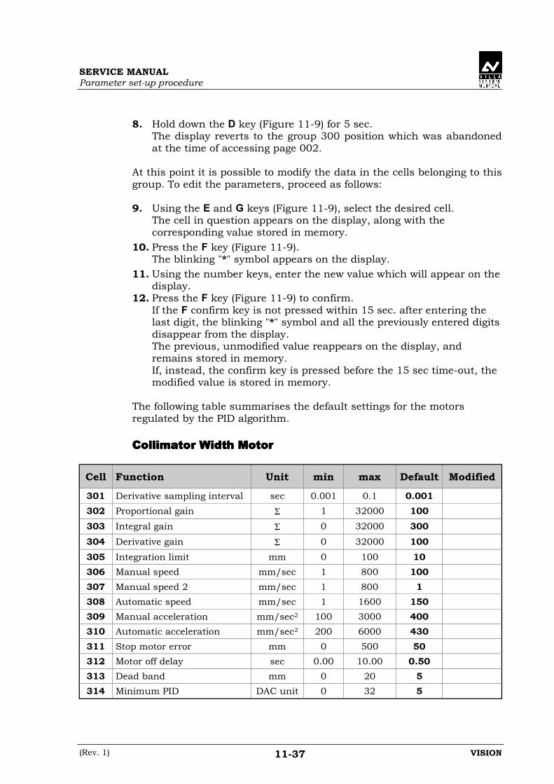
SERVICE MANUALParameter set-up procedure
(Rev. 1) VISION11-37
8. Hold down the D key (Figure 11-9) for 5 sec.The display reverts to the group 300 position which was abandonedat the time of accessing page 002.
At this point it is possible to modify the data in the cells belonging to thisgroup. To edit the parameters, proceed as follows:
9. Using the E and G keys (Figure 11-9), select the desired cell.The cell in question appears on the display, along with thecorresponding value stored in memory.
10. Press the F key (Figure 11-9).The blinking "*" symbol appears on the display.
11. Using the number keys, enter the new value which will appear on thedisplay.
12. Press the F key (Figure 11-9) to confirm.If the F confirm key is not pressed within 15 sec. after entering thelast digit, the blinking "*" symbol and all the previously entered digitsdisappear from the display.The previous, unmodified value reappears on the display, andremains stored in memory.If, instead, the confirm key is pressed before the 15 sec time-out, themodified value is stored in memory.
The following table summarises the default settings for the motorsregulated by the PID algorithm.
Collimator Width MotorCollimator Width MotorCollimator Width MotorCollimator Width Motor
Cell Function Unit min max Default Modified
301 Derivative sampling interval sec 0.001 0.1 0.001302 Proportional gain Σ 1 32000 100303 Integral gain Σ 0 32000 300304 Derivative gain Σ 0 32000 100305 Integration limit mm 0 100 10306 Manual speed mm/sec 1 800 100307 Manual speed 2 mm/sec 1 800 1308 Automatic speed mm/sec 1 1600 150309 Manual acceleration mm/sec2 100 3000 400310 Automatic acceleration mm/sec2 200 6000 430311 Stop motor error mm 0 500 50312 Motor off delay sec 0.00 10.00 0.50313 Dead band mm 0 20 5314 Minimum PID DAC unit 0 32 5

SERVICE MANUALParameter set-up procedure
VISION (Rev. 1)11-38
Collimator Height MotorCollimator Height MotorCollimator Height MotorCollimator Height Motor
Cell Function Unit min Max Default Modified
315 Derivative sampling interval sec 0.001 0.1 0.001316 Proportional gain Σ 1 32000 100317 Integral gain Σ 0 32000 300318 Derivative gain Σ 0 32000 100319 Integration limit mm 0 100 10320 Manual speed mm/sec 1 800 100321 Manual speed 2 mm/sec 1 800 1322 Automatic speed mm/sec 1 1600 150323 Manual acceleration mm/sec2 100 3000 400324 Automatic acceleration mm/sec2 200 6000 430325 Stop motor error mm 0 500 50326 Motor off delay sec 0.00 10.00 0.5327 Dead band mm 0 20 5328 Minimum PID DAC unit 0 32 5
Shutters MotorShutters MotorShutters MotorShutters Motor
Cell Function Unit min max Default Modified
329 Derivative sampling interval sec 0.001 0.1 0.001330 Proportional gain Σ 1 32000 2500331 Integral gain Σ 0 32000 300332 Derivative gain Σ 0 32000 2500333 Integration limit mm 0.0 500 10334 Initial speed mm/sec 0.1 500 100336 Working speed mm/sec 0.1 3000 500337 Initial acceleration mm/sec2 0.1 3000 250338 Working acceleration mm/sec2 0.1 3000 500339 Stop motor error mm 0.0 500 30340 Motor off delay sec 0.00 10.00 0.5342 Minimum PID DAC unit 0 32 5

SERVICE MANUALParameter set-up procedure
(Rev. 1) VISION11-39
Cassette Tray MotorCassette Tray MotorCassette Tray MotorCassette Tray Motor
Cell Function Unit min max Default Modified
343 Derivative sampling interval sec 0.001 0.1 0.001344 Proportional gain Σ 1 32000 2500345 Integral gain Σ 0 32000 300346 Derivative gain Σ 0 32000 3000347 Integration limit mm 0.0 500 10348 Initial speed mm/sec 0.1 500 100349 In-out speed mm/sec 0.1 999.9 500350 Working speed mm/sec 0.1 3000 400351 Initial acceleration mm/sec2 0.1 3000 250352 Working acceleration mm/sec2 0.1 6000 3000353 Stop motor error mm 0.0 500 30354 Motor off delay sec 0.00 10.00 0.5356 Minimum PID DAC unit 0 32 5

SERVICE MANUALParameter set-up procedure
VISION (Rev. 1)11-40
11.411.411.411.4 Accessing group 400/500/600 - Dimensions andAccessing group 400/500/600 - Dimensions andAccessing group 400/500/600 - Dimensions andAccessing group 400/500/600 - Dimensions andmovements rangemovements rangemovements rangemovements range
This group contains a broad range of parameters and functions.As for the other groups, it is possible to obtain read-only access to thedata contained in groups 400-500-600.Follow the procedure below:1. Turn off the equipment and place switches 1 and 2 (Dip-switch Q16
of SFD CPU board A1) in the ON position.2. Turn on the equipment.
The display shows:- the number of the group and the selected cell- the value stored in memory.
3. Using the G and E keys (Figure 11-9) it is possible to respectivelyincrease or decrease the number of the cell shown on the display. Asmentioned previously, in this phase it is not possible to modify any ofthe settings.
To modify the parameters:
4. Press the D key (Figure 11-9) for 5 sec.After this time has elapsed, the display will show:- 002 indicating the page number used for entering the passwords- 00000 waiting for the password to be entered.
5. Press the F key (Figure 11-9).The blinking "*" symbol appears on the display, prompting forentering the password.
6. Enter the password for this data group (Ref. 3 pg.11-1) using thenumber keys.This value will appear scrolling from right to left on the display.
7. Press the F key (Figure 11-9) to confirm.If the confirm key is not pressed within 15 sec. after entering the lastdigit, the blinking "*" symbol and the previously entered digitsdisappear from the display.It will then be necessary to re-enter the password.If, instead, the confirm key is pressed before the 15 sec. time-out, theblinking C456 symbol appears on the display, indicating that thepassword has provided read-write access to groups 400-500-600,depending on which ones have their switches set to ON.
8. Hold down the D key (Figure 11-9) for 5 sec.The display reverts to the group 400 position which was abandonedat the time of accessing.

SERVICE MANUALParameter set-up procedure
(Rev. 1) VISION11-41
Now the system allows to modify the data in the cells belonging to thisgroup. To modify the data, proceed as follows:
9. Use the E and G keys (Figure 11-9) to select the desired cell.The cell in question appears on the display, and the value stored inmemory is shown.
10. Press the F key (Figure 11-9).The blinking "*" symbol appears on the display.
11. Using the number keys, enter the new value, which will then appearon the display.
12. Press the F key (Figure 11-9) to confirm.If the confirm key F is not pressed within 15 sec. after entering thelast digit, the blinking "*" symbol and the previously entered digitsdisappear from the display.The display will revert to showing the previous unmodified value,which remains stored in memory.If, instead, the confirm key is pressed within the 15 sec time-out, thenew modified value will be stored in memory.
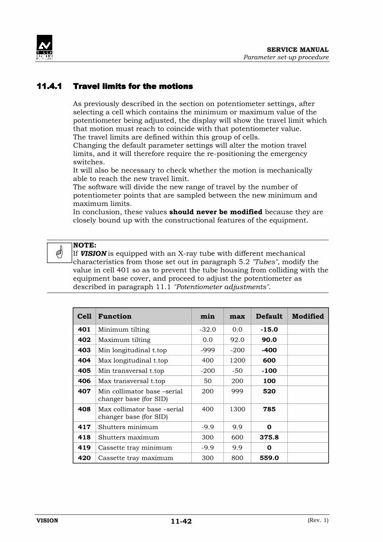
SERVICE MANUALParameter set-up procedure
VISION (Rev. 1)11-42
11.4.111.4.111.4.111.4.1 Travel limits for the motionsTravel limits for the motionsTravel limits for the motionsTravel limits for the motions
As previously described in the section on potentiometer settings, afterselecting a cell which contains the minimum or maximum value of thepotentiometer being adjusted, the display will show the travel limit whichthat motion must reach to coincide with that potentiometer value.The travel limits are defined within this group of cells.Changing the default parameter settings will alter the motion travellimits, and it will therefore require the re-positioning the emergencyswitches.It will also be necessary to check whether the motion is mechanicallyable to reach the new travel limit.The software will divide the new range of travel by the number ofpotentiometer points that are sampled between the new minimum andmaximum limits.In conclusion, these values should never be modified because they areclosely bound up with the constructional features of the equipment.
NOTE:If VISION is equipped with an X-ray tube with different mechanicalcharacteristics from those set out in paragraph 5.2 "Tubes", modify thevalue in cell 401 so as to prevent the tube housing from colliding with theequipment base cover, and proceed to adjust the potentiometer asdescribed in paragraph 11.1 "Potentiometer adjustments".
Cell Function min max Default Modified
401 Minimum tilting -32.0 0.0 -15.0402 Maximum tilting 0.0 92.0 90.0403 Min longitudinal t.top -999 -200 -400404 Max longitudinal t.top 400 1200 600405 Min transversal t.top -200 -50 -100406 Max transversal t.top 50 200 100407 Min collimator base –serial
changer base (for SID)200 999 520
408 Max collimator base –serialchanger base (for SID)
400 1300 785
417 Shutters minimum -9.9 9.9 0418 Shutters maximum 300 600 375.8419 Cassette tray minimum -9.9 9.9 0420 Cassette tray maximum 300 800 559.0

SERVICE MANUALParameter set-up procedure
(Rev. 1) VISION11-43
11.4.211.4.211.4.211.4.2 Dimensions of some parts of the equipmentDimensions of some parts of the equipmentDimensions of some parts of the equipmentDimensions of some parts of the equipment
This block of data contains some typical dimensions of the equipment.These dimensions are used by the software to calculate the collisionlimits.Clearly, therefore, these parameters are closely dependent on theequipment hardware, and must never be modified to avoidcompromising the equipment’s operation.
Cell Function min max Default Modific
433 Tilting centre height 100 700 700434 Tilting centre – lower
tabletop distance.10 400 185
435 Tabletop thickness 10 100 40436 Left tabletop length 900 2500 1395437 Right tabletop length. -1000 -200 -625438 Collimator base – focus dist. 10 150 80439 Serial changer base –
shutters distance0 100 11
440 Serial changer base – filmdistance
10 200 69
441 Serial changer base -I.I. dist. 0 250 118442 Cassette tray loading
position.300 900 562.5
457 Collimator lamp –adjustment mask distance
300 900 700
458 Shutters switch 0 offset -20.0 20.0 0
SERVICE MANUALParameter set-up procedure
VISION (Rev. 1)11-44
11.4.311.4.311.4.311.4.3 Potentiometer control data for single fault functionPotentiometer control data for single fault functionPotentiometer control data for single fault functionPotentiometer control data for single fault function
This group consists of the following cells:
443-444-445443-444-445443-444-445443-444-445Which contain the maximum allowed error between the theoretical andreal potentiometer values for the tilting, longitudinal and transversaltabletop motions.The theoretical motion is calculated using the speed values in cells 216,217 and 218, determined by the characteristics of the equipment.The unit of measurement of these cells is mm.
446446446446÷÷÷÷454454454454These cells determine the potentiometer sampling window for the SingleFault (SF) safety. As explained in the separate section, the processorchecks that the motion potentiometer values do not change when themotions themselves are inactive.This is done to assure SF safety.The value entered in this cell should take into account any residualinertial movements after the motion is halted.To facilitate the interpretation of this parameter, the units ofmeasurement can be expressed in degrees or millimetres.The greater the value of this parameter, the longer the movement cancontinue after the motion is halted before the microprocessor generatesan alarm.
455455455455This parameter determines the amount of additional travel allowed afterreaching the software limits as read by the potentiometer, before analarm is generated.This extra travel can be the result of the dead bands, for example.If the extra travel of the potentiometer exceeds the value entered in thiscell, an alarm will be generated to indicate that the potentiometer is tooclose to the limit.This makes it possible to detect whether a potentiometer circuit isinterrupted at power up.As for the previous cell, the unit of measurement is in "potentiometerdigital value".
456456456456This parameter configures the SF safety relative to the joystickmovements.The delay entered in this cell, expressed in seconds, determines a time-window within which no SF alarm is generated (231 or 232), to mask thenon-simultaneous mechanical activation of the switches by the joysticks.

SERVICE MANUALParameter set-up procedure
(Rev. 1) VISION11-45
Cell Function min max Default Modified
443 Max tilting motionpotentiometer error
0.5 20 10
444 Max longitudinal t.topmotion potentiometer error
5 500 100
445 Max. transversal t.topmotion potentiometer error
5 500 30
446 Max tilting travel whenmotion inactive
0.5 10 2
447 Max. longitudinal t.toptravel when motion inactive
5 100 10
448 Max. transversal t.top travelwhen motion inactive
5 100 10
449 Max SID travel with brakesengaged
5 100 10
450 Max widht collimator travelwhen motion inactive
0 99 10
451 Max. height collimator travelwhen motion inactive
0 99 10
452 Max shutters travel whenmotion inactive
0.5 10 10
453 Max cassette tray travelwhen motion inactive
0.5 10 10
454 Max analog. format signaldeviation with tray in park
5 4000 2000
455 SW limit overshootpotentiometers
0 100 100
456 Joystick S.F. alarm delay 0.10 5.00 5.00
SERVICE MANUALParameter set-up procedure
VISION (Rev. 1)11-46
11.4.411.4.411.4.411.4.4 Travel limits for serial changer shutters and cassette trayTravel limits for serial changer shutters and cassette trayTravel limits for serial changer shutters and cassette trayTravel limits for serial changer shutters and cassette tray
This group contains the travel limits for the motion of the serial changershutters and cassette tray for obtaining the different cassettesub-division programs.If the lines separating the radiographs of certain divisions needsadjustment, these travel limits can be adjusted by carefully following theinstructions in chapter 17 "Checking the radiographic results".
NOTE:1. the cassette tray and shutters positions may not match the value
entered in the corresponding cell; this is due to the mechanicalinertia of the system.In any case, the correction value in mm entered in the cells has theeffect of increasing or decreasing the final position by that amount.
2. The shutters values shown in the "Real Size" refer to the shutterswindow for the passage of the X-ray at the minimum SID. As in point1 of this note, the values contained in the "default" column do notcorrespond to the real measurement.
Cell Format Division Default Real size Modified
461 18x24 full size 293.0462 18x24 2 line-4 cross run 1 and 3 248.5463 18x24 2 line-4 cross run 2 and 4 337.5464 24x18 full size 323.0465 24x18 2 line run 1 263.5466 24x18 2 line run 2 382.5467 24x30 full size 323.0468 24x30 2 line run 1 263.5469 24x30 2 line run 2 382.5470 30x24 full size 353.0471 30x24 2 line-4 cross run 1 and 3 278.5472 30x24 2 line-4 cross run 2 and 4 427.5473 30x24 3 line-6 cross run 1 and 4 253.7474 30x24 3 line-6 cross run 2 and 5 353.0475 30x24 3 line-6 cross run 3 and 6 452.3476 30x30 full size 353.0477 30x30 2 line run 1 278.5478 30x30 2 line run 2 427.5479 30x30 3 line run 1 253.7480 30x30 3 line run 2 353.0481 30x30 3 line run 3 452.3

SERVICE MANUALParameter set-up procedure
(Rev. 1) VISION11-47
Cell Format Division Default Real size Modified
482 35x35 full size 381.0483 35x35 2 line run 1 292.5484 35x35 2 line run 2 469.5485 35x35 3 line run 1 263.0486 35x35 3 line run 2 381.0487 35x35 3 line run 3 499.0488 18 Shutters full size 176.6 166.2489 18 Shutters 2 line 81.8 080.3490 18 Shutters 4 cross 89.8 080.3491 24 Shutters full size 237.8 221.6492 24 Shutters 2 line 112.5 108.0493 30 Shutters full size 299.7 277.1494 30 Shutters 2 line 142.9 135.7495 30 Shutters 4 cross 151.0 135.7496 30 Shutters 3 line 92.3 089.9497 30 Shutters 6 cross 100.5 089.9498 35 Shutters full size 356.3 328.8499 35 Shutters 2 line 171.5 161.6500 35 Shutters 3 line 111.6 107.1501 8x10 full size 302.6502 8x10 2 line-4 cross run 1 and 3 252.2503 8x10 2 line-4 cross run 2 and 4 353.0504 10x8 full size 328.0505 10x8 2 line run 1 264.8506 10x8 2 line run 2 391.2507 10x12 full size 328.0508 10x12 2 line run 1 264.8509 10x12 2 line run 2 391.2510 12x10 full size 353.4511 12x10 2 line run 1 277.6512 12x10 2 line run 2 429.2513 12x10 3 line run 1 252.3514 12x10 3 line run 2 353.4515 12x10 3 line run 3 454.5516 9.5x9.5 full size 321.6517 9.5x9.5 2 line-4 cross run 1 and 3 261.9518 9.5x9.5 2 line-4 cross run 2 and 4 381.3519 9.5x9.5 3 line-6 cross run 1 and 4 241.9520 9.5x9.5 3 line-6 cross run 2 and 5 321.6
SERVICE MANUALParameter set-up procedure
VISION (Rev. 1)11-48
Cell Format Division Default Real size Modified
521 9.5x9.5 3 line-6 cross run 3 and 6 401.3522 14x14 full size 379.0523 14x14 2 line run 1 290.5524 14x14 2 line run 2 467.5525 14x14 3 line run 1 261.0526 14x14 3 line run 2 379.0527 14x14 3 line run 3 497.0528 8 Shutters full size 200.2 188.0529 8 Shutters 2 line 95.0 091.2530 10 Shutters full size 251.4 235.3531 10 Shutters 2 line 120.9 114.9532 12 Shutters full size 300.8 281.9533 12 Shutters 2 line 146.0 138.1534 12 Shutters 3 line 95.2 091.5535 9.5 Shutters full size 237.9 222.6536 9.5 Shutters 2 line 113.8 108.5537 9.5 Shutters 3 line 73.7 071.7538 9.5 Shutters 4 cross 116.9 108.5539 9.5 Shutters 6 cross 76.5 071.7540 14 Shutters full size 361.4 328.8541 14 Shutters 2 line 171.6 161.6542 14 Shutters 3 line 112.3 107.1543 8x10 3 line-6 cross run 1 and 4 235.4544 8x10 3 line-6 cross run 2 and 5 302.6545 8x10 3 line-6 cross run 3 and 6 369.8546 8 Shutters 4 cross 97.8 091.2547 8 Shutters 3 line 61.1 060.2548 8 Shutters 6 cross 64.3 060.2
SERVICE MANUALParameter set-up procedure
(Rev. 1) VISION11-49
11.4.511.4.511.4.511.4.5 Safety factors for PID regulated motionsSafety factors for PID regulated motionsSafety factors for PID regulated motionsSafety factors for PID regulated motions
If the software-generated PID value sent to the motor drives differs fromthe speed feedback measured by the potentiometers, the system must beable to recognise this effect and halt the equipment.This problem may be due to mechanical binding, or to slippage in thetransmission to the potentiometer.For each of the PID-regulated motions, there are 2 values whichdetermine the amount of deviation between PID and speed which triggersan alarm, and the delay after which such alarm is generated.
• Deviation timeIs expressed in seconds and allows to mask any transient spikes inthe PID value caused by inertia.In the event of a real anomaly, the higher this value is, the longer themotion will continue before generating an alarm.
• k factorThe factor by which the PID value is divided (PID/k).The software compares the speed with the value of PID/k. Because kis the denominator, the greater the value of k, the smaller the valueof the fraction.Because the alarm is generated if PID/k > speed, the smaller thevalue of PID/k, the longer the time for which a motion affected bymechanical binding will be accepted without generating an alarm.In general, increasing the values of time and k for any given motionwill increase its tolerance to "binding", permitting a broaduncontrolled movement before generating an alarm.
Cell Function Min Max Default Modified
551 Collimator width: k factor 1 30000 10000552 Collimator width: detection
delay0.0 9.9 1.0
553 Collimator height : k factor 1 30000 10000554 Collimator height: detection
delay0.0 9.9 1.0
555 Shutters: k factor 100 30000 5000556 Shutters: detection delay 0.0 9.9 1.0557 Cassette tray: k factor 100 30000 10000558 Cassette tray: detection
delay0.0 9.9 1.0

SERVICE MANUALParameter set-up procedure
VISION (Rev. 1)11-50
11.511.511.511.5 Accessing group 700 - EEPROM duplicationAccessing group 700 - EEPROM duplicationAccessing group 700 - EEPROM duplicationAccessing group 700 - EEPROM duplication
This program is used for copying the EEPROM data.This component stores all the parameters necessary for the equipment’soperation.At each power-up, these parameters are loaded into the RAM.In order to duplicate this data on a second EEPROM for backuppurposes, proceed as follows:
1. Turn off the equipment and place switches 1 and 3 (Dip-switch Q16of SFD CPU board A1) in the ON position.
2. Turn on the equipment.The display shows:- 701 corresponding to the first phase of this program- EEPROM – RAM, indicating the possibility of copying data from
EEPROM to RAM.
To perform the data transfer, the system requires entering the passwordas follows:
3. Press the D key (Figure 11-9) for 5 sec.After this time has elapsed, the display shows:- 002, the page number used for entering the passwords- 00000 waiting for the password to be entered.
4. Press the F key (Figure 11-9).The blinking "*" symbol appears on the display, prompting forentering the password.
5. Enter the password for this data group (Ref. 1 pg. 11-1) using thenumber keys.The value will be shown scrolling from right to left on the display.
6. Press the F key (Figure 11-9) to confirm.If the confirm key is not pressed within 15 sec. after entering the lastdigit, the blinking "*" symbol and the previously entered digitsdisappear from the display.It will then be necessary to re-enter the password.If, instead, the confirm key is pressed within the 15 sec. time-out, theblinking C137 message appears on the display, indicating that theentered password has granted access to groups 100-300-700,depending on which ones have their switch set to ON.
7. Hold down the D key (Figure 11-9) for 5 sec.The display reverts to the cell position 701 abandoned at the time ofaccessing page 002.

SERVICE MANUALParameter set-up procedure
(Rev. 1) VISION11-51
At this point it is possible to upload the data from the EEPROM to theRAM. To perform the copy operation, proceed as follows:
8. Press the F key (Figure 11-9).The blinking "*" symbol appears on the display, indicating that theparameters can be modified.
9. Press the A key to enable copying.The “DATA TRANSFER” message appears on the display.After approximately 5 sec., if the copy operation was successful, the“TRANSFER COMPLETED” message appears on the display.
At this point, coping of the data from the RAM into a new EEPROM canbe done, as follow:
10. Switch off the equipment, remove the EEPROM and insert a new onewhich must necessarily be of the same type and make (24C16 SGSThomson).
11. Switch on the equipment.Alarm 090 appears on the display console. This alarm is generatedbecause the new EEPROM does not contain the Checksum, andtherefore the RAM is unable to perform the check and thus generatesthe mentioned alarm.
12. Reset the alarm using the reset joystick.The display shows:- 702 corresponding to the first phase of this program- RAM – EEPROM, indicating the possibility of copying data from
RAM to EEPROMDuring this phase it is not necessary to enter the password, which isretained in memory from the previous phase of the EEPROM copyingoperation.
Now the system allows copying the data from RAM to EEPROM.To perform the copy operation, proceed as follows:
13. Press the A key (Figure 11-9) to enable copying.The “DATA TRANSFER” message appears on the display.After approximately 5 sec., if the copy operation was successful, the“TRANSFER COMPLETED” message appears on the display.
At this point, the procedure of copying data from one EEPROM toanother, using the RAM as an intermediate storage location, is complete.
The system allow copying of the data resident in the RAM to severalEEPROMs.This operation is streamlined because, if the equipment is switched offafter executing the transfer from RAM to EEPROM, at the next power upthe program will reposition itself on cell 702, ready to perform anothercopy operation as described above, and generating alarm 090 at eachpower up if a new EEPROM is installed.

SERVICE MANUALParameter set-up procedure
VISION (Rev. 1)11-52
If the data transfer from RAM to EEPROM is not performed, when theequipment is switched off and on again, the program repositions itself oncell 701, once again prompting for entering the password and for the datato be loaded into RAM.
If an error occurs during this procedure, the display shows thecorresponding diagnostic messages (see paragraph 18.2 "Non resettablediagnostics").
SERVICE MANUALParameter set-up procedure
(Rev. 1) VISION11-53
11.611.611.611.6 Accessing group 800 - Serial changer life testAccessing group 800 - Serial changer life testAccessing group 800 - Serial changer life testAccessing group 800 - Serial changer life test
This program is used for testing the movements of the serial changer andcollimator.During the testing phase, this program is used to perform a “life test” onthe serial changer and collimator by running a given number of cycles.The number of cycles performed by this program is shown on the consoledisplay.
It may also be necessary to perform this test after the equipment hasbeen installed.In fact, this test checks the functionality of all the serial changercomponents, enabling the service technician to carefully evaluate theperformance of the equipment.
To run this test, proceed as follows:
1. Turn off the equipment and place switches 2 and 3 (Dip-switch Q16of SFD CPU board A1) in the ON position.
2. Turn on the equipment.The display shows:- 800 corresponding to this program- the number of cycles performed so far.
3. Insert a 30x24 cassette in the serial changer tray.4. Press the load cassette button. If the cassette is recognised, the
program begins, otherwise it is ejected and the "WRONG CASSETTE –INSERT 30X24" message appears on the display.
In this program, the password needs to be entered only to modify thenumber of cycles shown on the display.This parameter can also be edited while the test cycle motions are inprogress, as follow:
5. Press the D key (Figure 11-9) for 5 sec.After this time has elapsed, the display shows:- 002, the page number used for entering the password.- 00000 waiting for the password to be entered.
6. Press the F key (Figure 11-9).The blinking "*" symbol appears on the display, prompting forentering the password.
7. Enter the password for this data group (Ref. 3 pg. 11-1) using thenumber keys.This value will be shown scrolling from right to left on the display.
SERVICE MANUALParameter set-up procedure
VISION (Rev. 1)11-54
8. Press the F key (Figure 11-9) to confirm.If the confirm key is not pressed within15 sec. after entering the lastdigit, the blinking "*" symbol and all the previously entered digitsdisappear from the display.It will then be necessary to re-enter the password.If, instead, the confirm key is pressed within the 15 sec. time-out, theblinking C4568 message appears on the display, indicating that theentered password has granted access to groups 400-500-600-800,depending on which switches are set to ON.
9. Hold down the D key (Figure 11-9) for 5 sec.The display reverts to the cell 800 position which was abandoned atthe time of accessing page 002.
At this point it is possible to modify the number of cycles shown on thedisplay. To modify the value:
10. Press the F key (Figure 11-9).The blinking "*" symbol appears on the display.
11. Use the number keys to enter the new value.12. Press the F key (Figure 11-9) to confirm.
If the confirm key F is not pressed within 15 sec. of entering the lastdigit, the blinking "*" symbol and all the previously entered digitsdisappear from the display.The previous unmodified value will reappear, and remain stored inmemory.If the confirm key is pressed within the established time-out, themodified value will be stored in memory.

SERVICE MANUALParameter set-up procedure
(Rev. 1) VISION11-55
11.6.111.6.111.6.111.6.1 Running the life test programRunning the life test programRunning the life test programRunning the life test program
The life test program consists of 6 different cycles involving a variety ofmotions.The cycles are described in detail below.
• Cycle ACycle ACycle ACycle A
The following motions are started simultaneously:- cassette tray to 30 full size position- shutters to 30 full size format- grid activated for 2 sec- collimator to 30x30 format.
After completing the above motions:- cassette tray to parked position- shutters to 35x35 full size position- grid to position 0- collimator to 35x35 format- increment the number of cycles executed by 1.
• CycleCycleCycleCycle BBBB
The following motions are started simultaneously:- cassette tray to 30/2 run 1 position- shutters to 30/2 format- grid activated for 2 sec- collimator to 15x15 format.
After completing the above motions:- cassette tray to parked position- shutters to 35x35 full size position- grid to position 0- collimator to 35x35 format- increment number of cycles executed by 1.

SERVICE MANUALParameter set-up procedure
VISION (Rev. 1)11-56
• Cycle CCycle CCycle CCycle C
The following motions are started simultaneously:- cassette tray to 30/2 run 2 position- shutters to 30/2 format- grid enabled for 2 sec- collimator to 15x15 format
At the end of the above motions:- cassette tray to parked position- shutters to 35x35 full size position- grid to position 0- collimator to 35x35 format- increment number of cycles executed by 1.
• Cycle DCycle DCycle DCycle D
The following motions are started simultaneously:- actuate upper rail coil for 1 sec- cassette tray to 30/4 cross run 2 position- shutters in 18/4 cross format- compressor to field- grid activated for 2 sec- collimator to 9x9 format.
At the end of the above motions:- enable upper rail coil until cassette tray reaches parked position- cassette tray to parked position- shutters to 35x35 full size position- compressor to parked position- grid to position 0- collimator to 35x35 format- increment the number of cycles executed by 1.

SERVICE MANUALParameter set-up procedure
(Rev. 1) VISION11-57
• Cycle ECycle ECycle ECycle E
The following motions are started simultaneously:- activate low rail coil for 1 sec- cassette tray to 30/4 cross run 4 position- shutters to 18/4 cross format- compressor in field- grid enabled for 2 sec- collimator to 9x9 format.
At the end of the above motions:- activate low rail coil until cassette reaches the parked pos.- cassette to parked position- shutters to 35x35 full size position- compressor parked- grid to position 0- collimator to 35x35 format- increment number of cycles executed by 1.
• Cycle FCycle FCycle FCycle F
The following motions are started simultaneously:- tray to cassette loading position- wait 0.5 sec- tray to parked position- shutters to 35x35 full size position- increment number of cycles executed by 1.
The 6 cycles are continually repeated in the above order.
NOTE:These motion sequences have been devised so as to simulate all themovements and cover the full range of travel of each motion.

SERVICE MANUALParameter set-up procedure
VISION (Rev. 1)11-58
THIS PAGE IS INTENTIONALLY LEFT BLANK
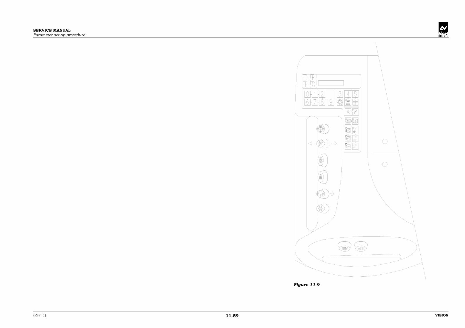
SERVICE MANUALParameter set-up procedure
(Rev. 1) VISION11-59
Figure 11-9
SERVICE MANUALSingle fault operation logic
(Rev. 1) VISION12-1
12.12.12.12. SINGLE FAULT OPERATION LOGICSINGLE FAULT OPERATION LOGICSINGLE FAULT OPERATION LOGICSINGLE FAULT OPERATION LOGIC
12.112.112.112.1 Theory of operationTheory of operationTheory of operationTheory of operation
The implementation of "Single Fault" (SF) safety is based on establishingredundant control over the circuits which actuate the table motions, i.e.those functions which could represent a hazard to the patient if theybecome uncontrolled.The safety logic is implemented so that, provided only one fault occurs ata time (from which the term Single Fault) at the various levels of themotion actuation chain, the system will be able to identify the fault andimmediately halt the motion.
The following paragraphs describe in detail how the single fault concepthas been implemented on VISION.This implementation complies with the most stringent interpretation ofthe regulations, assuring an extremely high safety factor and maintaininga high level of reliability and simplicity.In the event of a fault at any level of the motion actuation chain, itssophisticated technology and rapid response time enables this system toshut down any uncontrolled linear or angular motions within extremelyshort travel distances, as measured from the moment when the faultoccurs.

SERVICE MANUALSingle fault operation logic
VISION (Rev. 1)12-2
12.212.212.212.2 Hardware ImplementationHardware ImplementationHardware ImplementationHardware Implementation
The following motions:• tilting• longitudinal tabletop• transversal tabletopon VISION the SF safety concept described above.
The SFD CPU board (A1) incorporates an additional “supervisor”processor, which communicates with the main CPU processor toguarantee a redundant check on the above motions.All the motion controls of the main panel, preparation-exposure andfluoroscopy switches, as well as those of the on-board table panel, areimplemented using complementary-contact switches.The first open contact (NO) sends the motion request to the CPU.The second closed contact (NC) is in series with all the other NC contactsof the motion switches, and implements the SF safety function.The series connection provides a signal which is connected to an inputon the CPU processor and to an input on the monitor processor.This input, polarised at 0 Vs, is activated (active at 0 Vs) when all themotions are at halt, i.e. when no motion control has been operated, andthe signal is reset (0 Vs absent) when one or more controls are activated.
Here follows the motions equipped with potentiometer feedback:• tilting• longitudinal tabletop• transverse tabletop.
The HW components installed on VISION for implementing the SF safetyare:
• Table2-way switch for all the panel and dual motion controls.
• Main processor- provision of an input for the NC switch contacts (SF input)- provision of 6 outputs for relaying the state of the output ports
which control the actuation of the above described motions.- provision of a serial link toward the supervisor processor, to cross
check the operation of the electronics on both parts of the circuitboard.
- provision of a "ready" relay on the SFD CPU board (A1).• Supervisor processor
Implementation of a “monitor” function on the SFD CPU board (A1)with:- provision of a "ready" relay- provision of an input for the NC switch contacts (SF input)- 6 inputs for monitoring the motion control ports- serial link for communicating with the primary CPU processor.
SERVICE MANUALSingle fault operation logic
(Rev. 1) VISION12-3
12.312.312.312.3 Software implementation and operating principleSoftware implementation and operating principleSoftware implementation and operating principleSoftware implementation and operating principle
The software implementation of the SF safety related functions isdescribed below:
• Switch-onWhen the equipment is powered up, the main processor and thesupervisor perform a cross-check on the operation of both electronicssections by means of the serial link.Both processors check that the motion control input is in the “allcontrols inactive” status.The 6 output ports must be inactive, and this is checked by themonitor using the 6 monitoring inputs.If all the above conditions are met, both the main processor and thesupervisor activate their “ready” relays, whose series-connected opencontacts energise the coil of power contactor K1L, thereby supplyingthe power circuits.When the “ready” relay is energised, none of the motion feedbacksignals, from the potentiometers must be active.If the conditions described in the previous points are not met, the“ready” relays will not be energised and the main processor will sendan alarm diagnostic to the display.
• Actuation of one or more motionsWhen a motion is requested, the CPU receives the information as towhich motion should be actuated via the input lines which connect itto the control panel with dual controls.At the same time, the SF input of the motion controls changes state.This input is also received by the supervisor.Both processors enable the activation of one or more output ports,and the main processor checks that the correspondingpotentiometers are in motion.When both the motion control and SF signal are reset, the mainprocessor and the supervisor check that the ports are immediatelyreset.The potentiometer feedback signals must also be immediately reset.
• MalfunctionsAs mentioned in the introduction, the system is able to detect amalfunction at any level of the control chain which actuates themotion.Therefore, the possible malfunctions are:1. Motion control microswitch fault2. SF microswitch fault3. Main processor fault4. Supervisor processor fault5. Motion actuation gate fault6. Motion drive component fault7. Feedback element fault.

SERVICE MANUALSingle fault operation logic
VISION (Rev. 1)12-4
The system is able to detect all the above mentioned faults, as describedbelow:
1 - 21 - 21 - 21 - 2The previous paragraphs describe the conditions for checking the motionactuation inputs and the corresponding alarm codes.
3333A malfunction in the electronics or serial communications section of themain processor is detected by the supervisor via the serial link which, asdescribed previously, resets the "ready" relay and turns on a red alarmled.
4444In the same way, and using the above mentioned serial link, the mainprocessor is able to detect a malfunction in the supervisor.If a malfunction is detected, the main processor resets its "ready" relayand sends an alarm diagnostic.
NOTE:The serial link between the 2 sections, in addition to monitoring thecorrect operation of the microprocessors, is used by the supervisor tocompare the inputs and the ports activated by the main processor.
5555Upon power-up, none of the motion actuation ports must be activated,and no motion request and SF signals should be activated.If this anomaly occurs, both the “ready” relays will be reset, and the mainprocessor will generate an alarm diagnostic for the defective port.
6666A malfunction in a hardware component of a motor drive may cause it toremain short circuited.The system is able to detect the fault thanks to the feedback receivedfrom the potentiometers.In this case, no motion control will be activated, no port will be ON, butthe main processor will nonetheless receive a feedback signal.The ready relays are immediately reset and the corresponding alarmdiagnostic is sent to the display.
7777In the event of a malfunction in a hardware component of the motioncontrol or feedback loop, the system detects that a motion control hasbeen activated, causing the SF circuit to open, and it detects that one ormore ports have been activated but that the corresponding potentiometerfeedback signals are absent.Because the system is able to compare the output ports with thefeedback signals, after resetting the ready relay, the main processorsends an error diagnostic to the display.

SERVICE MANUALOperating conditions
(Rev. 1) VISION13-1
13.13.13.13. OPERATING CONDITIONSOPERATING CONDITIONSOPERATING CONDITIONSOPERATING CONDITIONS
13.113.113.113.1 CollisionCollisionCollisionCollision
In certain cases, when one or more motions are activated, a part of thetabletop may reach the collision safety limit.This limit is set up in the following cells:• 201, 202, 203 (floor, wall, ceiling distances)• 210, 211, 212 (safety distances)and creates an imaginary software barrier which the motion cannotovercome.
When any part of the table reaches a collision limit, the motion inquestion is halted.A message indicating which collision limit has been reached appears onthe display.The collision messages are:
11 – T.top – left wall12 – T.top – right wall13 – T.top - ceiling14 – T.top - floorAt this point, the software inhibits any tilting and tabletop motions whichwould take it beyond the collision barrier.Only motions which retract the equipment from the collision limit will beenabled.
However, all the other functions of the equipment for performingexaminations, such fluoroscopy, preparation and radiography modes,remain available.
After removing the collision situation, the message on the displayautomatically disappears and motions in all directions are once againenabled.

SERVICE MANUALOperating conditions
VISION (Rev. 1)13-2
13.213.213.213.2 CollimatorCollimatorCollimatorCollimator
VISION has been designed to accommodate an automatic collimator withsquare-rectangular field.The collimator operating modes are:
• Automatic modeThe default positioning of the width and height shutters depends onthe selected I.I. field.The collimation size is determined by the parameter values in cells204, 205, 206.In fluoroscopy mode, the reduction joystick can be used to choose anintermediate format between fully-closed position and the active I.I.format.With a cassette sub-division program, the maximum format whichthe collimator can reach will be the smallest one between the I.I.format and the selected sub-division format.When the preparation control is pressed, the collimated format willcorrespond to the sub-division setting, even if it is larger than the I.I.or if the collimator field was previously reduced using the joystick.
• Automatic mode with holdThe operation of the collimator with the hold function enabled isdifferent from its standard operation, in that it retains any formatreductions made with the joystick in fluoroscopy mode.Infact, if a joystick reduction is made prior to pressing thepreparation control, this reduction will be retained when thepreparation control is pressed.If no format reduction is made, or if the joystick is used to return theshutters to the maximum allowed position, the operation will beidentical to that in automatic mode.

SERVICE MANUALOperating conditions
(Rev. 1) VISION13-3
13.313.313.313.3 Signal timingSignal timingSignal timingSignal timing
Before analysing in detail the exposure sequences described below, it isimportant to know the software timing of the output and input signals toand from the generator.The following graphs provide a clear overview of the signal timing.
Fluoroscopy modeFluoroscopy modeFluoroscopy modeFluoroscopy mode
OUT X0-4 Fluoroscopy
IN X0-22 X-ray ON
MAX 0.35 SEC (ALARM 64)
Radiography modeRadiography modeRadiography modeRadiography mode
OUT X0-5 Preparation
OUT X0-7 2nd step
IN X0-21 Generator ready
OUT X0-8 Radiography
IN X0-22 X-ray ON
MAX 0.35 SEC (AL.64)
MAX 3 SEC (ALARM 62)
SERVICE MANUALOperating conditions
VISION (Rev. 1)13-4
13.413.413.413.4 Standard radiographyStandard radiographyStandard radiographyStandard radiography
To take a standard radiography, it is necessary to follow an establishedsoftware sequence in order to complete the program.This sequence is as follows:
1. Exposure switch 1st step (preparation):- start cassette motion from PARKED position toward "exposure"
position- shutters motion toward cassette format if larger than the I.I.
format- “Preparation request" output active toward the generator- motion of collimator axis toward the radiograph format, if larger
than the I.I. format.
2. Exposure switch 2nd step:"2nd step" output active toward generator.
3. "Generator ready" input active:Start grid motion only if all the following conditions are met:- collimator axis halted on the selected film or sub-division size- shutters at the film or sub-division position, and motor off delay
(cell 340) elapsed- cassette at "exposure" position and motor off delay (cell 354)
elapsed.
4. Exposure request:- the grid motion initiates the countdown of the delay entered in
cell 215. When this time has elapsed:- "Exposure request" output active to generator.
5. X-ray present:The "X-ray ON" input must be active within 0.35 sec.Otherwise alarm 064 will be generated.
The above described sequences are illustrated in the following flowdiagram, which shows the "standard exposure" function and theassociated alarm messages.

SERVICE MANUALOperating conditions
(Rev. 2) VISION13-5
13.4.113.4.113.4.113.4.1 Standard radiograph flow diagramStandard radiograph flow diagramStandard radiograph flow diagramStandard radiograph flow diagram
→→→→• Cassette parked• Shutters at I.I. or div.• Collimator at I.I. or div.
←←←←
↓↓↓↓Operatejoystick
reset1st step:• Motion toward exposure position of:- Cassette- Shutters- Collimator- Compressor idle• "Prep request" o/p ON
↓↓↓↓ ↑↑↑↑↑↑↑↑
NO
• Final position reached by:- Cassette- Shutters- Collimator- Compressor idle
within 8 sec.
→→→→Alarm060 →→→→
YES ↓↓↓↓NO2nd step to generator
• "Generat. Ready" input within 3 sec.
→→→→Alarm062 →→→→
YES ↓↓↓↓• Start grid motion• Countdown delay cell 215
↓↓↓↓ ↑↑↑↑• Cell. 215 delay elapsed:- "exp. request" active
↓↓↓↓↑↑↑↑ NO• "X-ray ON" input active
within 0.35 sec. →→→→Alarm064 →→→→
YES ↓↓↓↓ ↑↑↑↑
YESExposure in progress.• Release exposure switch with "X-ray ON" input active
→→→→
1st step: Alarm067
2nd step: Alarm066
→→→→
NO ↓↓↓↓ ↑↑↑↑YES• "X-ray ON" input active
for more than 6.5 sec. →→→→Alarm065 →→→→
NO ↓↓↓↓YES
←←←←• Release 1st and 2nd steps with exposure time elapsed ("X-ray ON" not active)
←←←←
NO ↓↓↓↓

SERVICE MANUALOperating conditions
VISION (Rev. 1)13-6
13.513.513.513.5 Rapid sequenceRapid sequenceRapid sequenceRapid sequence
Executing a rapid program involves a different software sequence fromthe standard program.The rapid sequence can only be selected for cassette sub-divisions withat least 2 exposures, and provided no exposure has yet been performed.The sequences of this program are:
1. Exposure switch 1st step (preparation):- start cassette motion from PARKED position toward "exposure”
position- shutters motion toward cassette format if larger than the I.I.
format- “Preparation request" output active toward the generator- motion of collimator axis toward the radiograph format if larger
than the I.I. format- start grid motion.
2. Exposure switch 2nd step:“2nd step” output active to generator.
3. "Generator ready" input active:Exposure request output active toward the generator if the followingconditions are true:- collimator axis halted on the selected sub-division size.- shutters at the sub-division position and motor off delay (cell
340) elapsed- cassette at "exposure" position and motor off delay (cell 354)
elapsed.
4. "X-ray ON" present:The "X-ray ON" input must be active within 0.35 sec.Otherwise, alarm 064 will be generated.
5. Advance with program:When the "X-ray ON" input is reset:- the "exposure" request output is reset- the cassette advances to the next "exposure" position.
6. Performing the next radiography:When the cassette has reached the "exposure" position and the motoroff delay (cell 354) has elapsed, the "exposure" request is once againactivated.
In any part of the sequence, if switch 2nd step is released, the program isaborted and the cassette is ejected, generating alarm 063.Any alarm which occurs during a rapid sequence program causes theprogram to be aborted, and the cassette to be ejected.
The above described sequences are illustrated in the following flowdiagram, which shows the “standard exposure” function and theassociated alarm messages.

SERVICE MANUALOperating conditions
(Rev. 2) VISION13-7
13.5.113.5.113.5.113.5.1 Rapid sequence program flow diagramRapid sequence program flow diagramRapid sequence program flow diagramRapid sequence program flow diagram
• Select div. and rapid seq.• Cassette parked• Shutters at II or div.• Collimator at II or div.
←←←←
↓↓↓↓ ↑↑↑↑Operate
alarm resetjoystick
↑↑↑↑
1st step:• Motion toward exposure pos. of:- Cassette- Shutters- Collimator- Compressor idle• "Prep request" o/p ON• Start grid motion
• Progr. aborted• Cassette eject
↓↓↓↓
NO↑↑↑↑
• Final position reached by:- Cassette- Shutters- Collimator- Compressor idle
within 8 sec.
→→→→ Alarm061 →→→→
YES ↓↓↓↓NO2nd step to generator
• "Generat. Ready" input within 3 sec.
→→→→Alarm062 →→→→
YES ↓↓↓↓• "Exposure request" ON ↑↑↑↑
↓↓↓↓NO• "X-ray ON" input active
within 0.35 sec. →→→→Alarm064 →→→→
YES ↓↓↓↓ ↑↑↑↑
NO→→→→
• "X-ray ON" input OFF (stop exposure) within: 6.5 sec- "Exposure request" output OFF
→→→→Alarm065 →→→→
YES ↓↓↓↓YES ↑↑↑↑• End of program →→→→ →→→→ →→→→
NO ↓↓↓↓ ↑↑↑↑YES• Exposure switch
released with program not finished
→→→→Alarm063 →→→→ ↓↓↓↓
NO ↓↓↓↓↑↑↑↑ ↑↑↑↑• Cassette at next
position• "Exposure request" output ON
↓↓↓↓YES NO
←←←←• "X-ray ON" input active within 3 sec. →→→→
Alarm064 →→→→
• Cassette out or parked (cell 230)

SERVICE MANUALOperating conditions
VISION (Rev. 1)13-8
13.613.613.613.6 Digital radiographyDigital radiographyDigital radiographyDigital radiography
The digital input can take place with the serial changer in 2 differentconditions:• without sub-divisions• with sub-divisions.
Therefore, if the digital function is selected in the just condition, it will bepossible to actuate the cassette motion, whereas in the second conditionthe cassette will remain locked in the parked position until digital modeis exited.
The sequences of the digital functions are:
1. Exposure switch 1st step (preparation):“Digital prep” request output to generator.
2. Exposure switch 2nd step:"2nd step” request output to generator.
3. "Generator ready" input active:“Exposure request" output to the generator active.
4. "X-ray ON" active:"X-ray ON" input must be activated within 0.35 sec.Otherwise alarm 064 will appear.
The above described sequence is illustrated in the following flow diagram,which shows the "standard exposure” function and the associatedalarms.

SERVICE MANUALOperating conditions
(Rev. 1) VISION13-9
13.6.113.6.113.6.113.6.1 Digital radiography flow diagramDigital radiography flow diagramDigital radiography flow diagramDigital radiography flow diagram
→→→→• Digital ON• Cassette tray parked ←←←←
↓↓↓↓Operatejoystick
reset1st step:• "Prep. request" o/p ON
↓↓↓↓NO2nd step to generator
• "Generat. Ready" input within 3 sec.
→→→→Alarm062 →→→→
YES ↓↓↓↓• "Exposure request" output ON
↓↓↓↓ ↑↑↑↑↑↑↑↑ NO• "X-ray ON" input active
within 0.35 sec. →→→→Alarm064 →→→→
YES ↓↓↓↓Exposure in progressDSI exposure rate. ←←←←
↓↓↓↓YES ↑↑↑↑
←←←←• Release 1st or 2nd steps in any condition
NO ↓↓↓↓

SERVICE MANUALOperating conditions
VISION (Rev. 1)13-10
THIS PAGE IS INTENTIONALLY LEFT BLANK

SERVICE MANUALEmergency safeties
(Rev. 1) VISION14-1
14.14.14.14. EMERGENCY SAFETIESEMERGENCY SAFETIESEMERGENCY SAFETIESEMERGENCY SAFETIES
As described in paragraph 9.2 "Error conditions", if a malfunction causesone of the table or serial changer motions to overshoot its software travellimit, the emergency switch for that motion will be intercepted.
In fact, to ensure maximum reliability and safety for the operator andpatient, all the motion travel limits of VISION are equipped withemergency switches, situated just a few millimetres beyond thecorresponding software travel limits.
If one of these switches is activated, alarm 080 or 081 appears on thedisplay to signal the malfunction.
In the case of alarm 080, it is necessary to determine which of thefollowing motions:• tilting• longitudinal tabletop• transversal tabletopis in the emergency position.
In the case of alarm 081, it means that the cassette tray or shutters haveactivated one of the emergency switches on the serial changer.
After switching off the system, it is necessary to identify the cause of thiscondition.Remove the cause of the alarm, and proceed as follows to resumeoperation:
Alarm 080Alarm 080Alarm 080Alarm 0801. Press the S1 reset button situated in the “circuit boards" area of the
serial changer.2. While keeping this button pressed, switch on the equipment.3. Wait for the initialisation cycle to be completed.4. Operate the joystick so as to retract the motion from the travel limit
which caused the alarm.5. Release button S1.
WARNING:Pressing the S1 button bypasses the series of emergency microswitches.Therefore, if the cause of the malfunction has not been corrected, there isthe danger of the motion continuing without the safety of the emergencymicroswitch.For the same reason, if at this point the motion is actuated in thedirection of the mechanical limit, i.e. taking it beyond the emergencyswitch, no safety will be tripped.It is therefore important to take every precaution to prevent collisions.
SERVICE MANUALEmergency safeties
VISION (Rev. 1)14-2
Alarm 081Alarm 081Alarm 081Alarm 081Unlike the table emergency circuit, there is no bypass switch for resettingthe serial changer emergency circuit.In fact, the 2 motions which can produce this condition, i.e. those of theshutters and the cassette tray, are not equipped with parking brakes.Therefore, if the shutters or cassette tray are in the emergency position,after correcting the fault it is necessary to manually move the shutters ortray away from the activated switch, with the equipment switched off, inorder to resume normal operation.

SERVICE MANUALHardware adjustments
(Rev. 1) VISION15-1
15.15.15.15. HARDWARE ADJUSTMENTSHARDWARE ADJUSTMENTSHARDWARE ADJUSTMENTSHARDWARE ADJUSTMENTS
The design and construction of VISION is based on sophisticated, state-of-the-art technology.However, its complex functionality has been implemented so as to ensureease of use and servicing.For this reason, all the settings and adjustments of the table functionsare performed via software, as described in chapter 11 "Parameter set-upprocedure".
There are no trimmers or adjustable components on the circuit boards,and therefore no instructions for hardware adjustments are necessary.The following paragraphs describe the jumper settings which configurethe circuit boards for standard operation.
15.115.115.115.1 SFD CPU board (A1)SFD CPU board (A1)SFD CPU board (A1)SFD CPU board (A1)
The microprocessor board is supplied already configured as describedbelow.This is true both for the circuit boards installed on the equipment, andfor those supplied as spare parts.A brief description of the various "jumper" settings is nonethelessprovided as additional information, and their positions are shown inFigure 15-1.
Select the type of EPROM or RAM used as component E1Select the type of EPROM or RAM used as component E1Select the type of EPROM or RAM used as component E1Select the type of EPROM or RAM used as component E1and E2.and E2.and E2.and E2.
• Jumpers used:Q1-2-3-4-5-6-7-8-9-10-11-12
• Possible settings:
EPROM Jumpers
512k x 8 1-5-7-9-11128k x 8 1-5-8-1164k x 8 1-5-6-1132k x 8 3-5-6-11
RAM Jumpers
128k x 8 2-4-6-10-1232k x 8 2-4-6-12

SERVICE MANUALHardware adjustments
VISION (Rev. 1)15-2
NOTE:The RAMs which can be used in these positions (E1 and E2) are not theRAMs for standard operation, but those used in the laboratory foremulation purposes.The components normally used in these positions are EPROMs.
• Standard operating configuration
EPROM Jumpers
128k x 8 1-5-8-11
Connecting the backup batteryConnecting the backup batteryConnecting the backup batteryConnecting the backup battery• Jumpers used:
Q13
• Standard operating configurationThe battery must be connected and then the jumper must beclosed.
Settings for serial link between the Main and SupervisorSettings for serial link between the Main and SupervisorSettings for serial link between the Main and SupervisorSettings for serial link between the Main and Supervisorprocessorprocessorprocessorprocessor
• Jumpers used:Q14-15
• Possible settings:Q14Positions 1-2 closed normal operationPositions 2-3 closed emulation
Q15Positions 1-2 closed normal operationPositions 2-3 closed emulation
• Standard operating configurationQ14The jumper must be closed on positions 1-2.
Q15The jumper must be closed on positions 1-2.

SERVICE MANUALHardware adjustments
(Rev. 1) VISION15-3
Figure 15-1
The " " symbol indicates which jumpers must be closed.

SERVICE MANUALHardware adjustments
VISION (Rev. 1)15-4
15.215.215.215.2 Cassette tray and shutters motors drive board (A2)Cassette tray and shutters motors drive board (A2)Cassette tray and shutters motors drive board (A2)Cassette tray and shutters motors drive board (A2)
This drive board does not require any hardware adjustments, andtherefore no adjustable components are included on this printed circuitboard.
Neither are there any "jumpers" for setting configurations.
SERVICE MANUALSpot film device board led description
(Rev. 1) VISION16-1
16.16.16.16. SPOT FILM DEVICE BOARD LEDSPOT FILM DEVICE BOARD LEDSPOT FILM DEVICE BOARD LEDSPOT FILM DEVICE BOARD LEDDESCRIPTIONDESCRIPTIONDESCRIPTIONDESCRIPTION
16.116.116.116.1 SFD CPU board (A1)SFD CPU board (A1)SFD CPU board (A1)SFD CPU board (A1)
The SFD CPU board (A1) is equipped with groups of LEDs that indicatethe following:• status of the outputs• status of power supply voltages• status of the main processor and of the supervisor.
NOTE:If not otherwise specified, normally the LEDs are OFF (not lit).When each listed function is active, the relevant LED is ON (lit).
Meaning of each LED is here after described.Figure 16-1 shows the LED location on the board.
• H5 LED GROUPH5 LED GROUPH5 LED GROUPH5 LED GROUP
Led 1 II minimum fieldLed 2 collimator movement enablingLed 3 collimator width movementLed 4 collimator height movementLed 5 shutters movementLed 6 shutters movement enablingLed 7 SFD cassettes tray movementLed 8 SFD cassettes tray movement enabling.
• H6 LED GROUPH6 LED GROUPH6 LED GROUPH6 LED GROUP
Led 1 fluoro requestLed 2 normal preparation requestLed 3 digital preparation requestLed 4 second stepLed 5 exposure requestLed 6 X-ray ON alarm without request (normally this LED is lit)Led 7 fluoro automatic kV adjustmentLed 8 main processor main relays (normally this LED is lit).

SERVICE MANUALSpot film device board led description
VISION (Rev. 1)16-2
• H7 LED GROUPH7 LED GROUPH7 LED GROUPH7 LED GROUP
Led 1 room light onLed 2 tilting movement towards trendelembourgLed 3 tilting movement towards verticalLed 4 transversal table top movement towards insideLed 5 transversal table top movement towards outsideLed 6 longitudinal table top movement towards foot sideLed 7 longitudinal table top movement towards head sideLed 8 servomotor movement towards foot side.
• H8 LED GROUPH8 LED GROUPH8 LED GROUPH8 LED GROUP
Led 1 servomotor movement towards head sideLed 2 longitudinal and transversal brakes activeLed 3 compressor brake activeLed 4 grid in movementLed 5 compressor moving to fieldLed 6 compressor moving to parkLed 7 "UP" rail coil active (for cross sub-division)Led 8 "DOWN" rail coil active (for cross sub-division)
• H9 LED GROUPH9 LED GROUPH9 LED GROUPH9 LED GROUP
Led 1 Spot Film Device and collimator readyLed 2 manual mode kV increasingLed 3 manual mode kV decreasingLed 4 motion detectionLed 5 0° and +10° tilting position output activeLed 6 +80° and +90° tilting position output activeLed 7 spareLed 8 spare.
• LED FOR OTHER FUNCTIONSLED FOR OTHER FUNCTIONSLED FOR OTHER FUNCTIONSLED FOR OTHER FUNCTIONS
H1 main processor resetH2 ready supervisor relays (normally this LED is lit)H3 supervisor resetH10 +5V power supply active (normally this LED is lit)H11 +24Vs power supply active (normally this LED is lit)H12 +15Vs power supply active (normally this LED is lit)H13 +12V supervisor power supply active (normally this
LED is lit)H14 +5V supervisor active (normally this LED is lit)
NOTE:The status of the output of some functions (e.g. medium II field) are notmonitored with LEDs.Therefore, some of the functions provided by the system are not listedabove.

SERVICE MANUALSpot film device board led description
(Rev. 1) VISION16-3
Figure 16-1
SERVICE MANUALSpot film device board led description
VISION (Rev. 1)16-4
16.216.216.216.2 Cassette tray and shutters motors drive board (A2)Cassette tray and shutters motors drive board (A2)Cassette tray and shutters motors drive board (A2)Cassette tray and shutters motors drive board (A2)
The motor driver board is equipped with LEDs that monitor the status ofthe relevant power supply voltages.The list here after indicates the LEDs and the relevant functions.Figure 16-2 shows the position of the LEDs on the board.
NOTE:If not otherwise specified, normally the LEDs are OFF (not lit).When each listed function is active, the relevant LED is ON (lit).
• MEANING OF THE LEDsMEANING OF THE LEDsMEANING OF THE LEDsMEANING OF THE LEDs
H1 ready relays ON (normally this LED is lit)H2 cassettes tray motor driver alarmH3 shutters motor driver alarm

SERVICE MANUALSpot film device board led description
(Rev. 1) VISION16-5
Figure 16-2

SERVICE MANUALSpot film device board led description
VISION (Rev. 1)16-6
THIS PAGE IS INTENTIONALLY LEFT BLANK

SERVICE MANUALChecking the radiographic results
(Rev. 1) VISION17-1
17.17.17.17. CHECKING THE RADIOGRAPHICCHECKING THE RADIOGRAPHICCHECKING THE RADIOGRAPHICCHECKING THE RADIOGRAPHICRESULTSRESULTSRESULTSRESULTS
After completing the installation of VISION, the quality of the filmsobtained must be checked in order to satisfy the user expectation.Possible anomalies may depend on the adjustment of components of thesystem. Each of them is here-after described.
The correctness of these adjustments must be evaluated as describedbelow.
17.117.117.117.1 Serial changer adjustmentSerial changer adjustmentSerial changer adjustmentSerial changer adjustment
The serial changer is adjusted and checked at the factory, during theassembly and testing of VISION. However, after completing theinstallation of the system and taking some test radiographs, it may benecessary to perform an additional calibration.
To check the correct positioning of the cassette tray along thelongitudinal and shutters axis, it is necessary to bypass the automaticcollimator function which may interfere with the limiting format.To automatically open the collimator to its largest format, enter value 1in cell 233 (utility function enabled).When this function is enabled, the "SERVICE mode" message appears onthe display.

SERVICE MANUALChecking the radiographic results
VISION (Rev. 1)17-2
17.1.117.1.117.1.117.1.1 Checking the longitudinal positioning of the cassette trayChecking the longitudinal positioning of the cassette trayChecking the longitudinal positioning of the cassette trayChecking the longitudinal positioning of the cassette tray
The positioning of the cassette tray must be precise, regardless of thetravel distance and the weight of the cassette.An effective method for checking this is the following:1. Insert a 30x24 cassette and select the 3 in-line sub-division.2. Run the program and develop the film.3. The 2 white lines separating the radiographs must be of equal width.4. Repeat this check using a 35x35 cassette with 3 sub-divisions.If the separation lines are uneven, the cassette positioning is not correctthroughout its range of travel.
NOTE:During this phase it is not significant to measure the width of theseparating lines, which is determined by the shutters positions, but it isimportant to obtain the same width for all the lines, as this is determinedby the cassette tray positioning.
Therefore, to correct any irregularities affecting the separating linewidths, it is necessary to modify the PID regulation gains in the cells ofgroup 300.
WARNING:Modifying these parameters can produce different effects, some of whichare undesirable; it is therefore recommended to change their values onlywith a good understanding of the PID method, and referring to the"Operating theory of a PID regulated axis" in paragraph 11.3.1.
The correction must be performed by adjusting the gains, because theirregularity is determined by the error difference accumulated as afunction of the travel distance.
In fact, correcting the individual travel distances using the parameters ingroup 400 would require a slow and laborious procedure, without solvingthe root of the problem.However, if the individual is not sufficiently familiar with the PID method,it is also possible to adopt this second approach.

SERVICE MANUALChecking the radiographic results
(Rev. 1) VISION17-3
17.1.217.1.217.1.217.1.2 Checking the transversal positioning of the cassette trayChecking the transversal positioning of the cassette trayChecking the transversal positioning of the cassette trayChecking the transversal positioning of the cassette tray
When taking a set of radiographs with cross sub-division on 18x24 or30x24 film, a continuous separation line approximately 2 mm thickshould be obtained between the upper and lower radiographs.
If this is not the case, it means that the transversal positioning of thecassettes tray is incorrect.The accuracy of this motion is determined by the mechanical guides onthe serial changer plate.Therefore, any adjustments can only be made by referring to VILLASISTEMI MEDICALI S.p.a..
17.1.317.1.317.1.317.1.3 Checking the positioning of the shuttersChecking the positioning of the shuttersChecking the positioning of the shuttersChecking the positioning of the shutters
1. Perform exposures on films of different formats with various sub-division settings.
2. All the separator lines, for the various film formats and sub-divisionsettings, should be of equal thickness.
3. If this is not the case, modify the group 400 parameters so as tocorrect any errors.
NOTE:The cassette tray and shutters positions may not match themeasurement entered in the corresponding cell; this is due to themechanical inertia of the system.In any case, the mm correction entered in these cells will increase ordecrease the final position by an equivalent amount.The theoretical travel limit of shutters is given in the "Actual travel"column of the tables in paragraph 11.4 "Dimensions and movementsrange".

SERVICE MANUALChecking the radiographic results
VISION (Rev. 1)17-4
17.217.217.217.2 Collimator adjustmentsCollimator adjustmentsCollimator adjustmentsCollimator adjustments
The collimator is adjusted and checked at the factory, during theassembly and testing of VISION. However, after completing theinstallation of the system and taking some test radiographs, it may benecessary to perform some additional adjustments.
Using the different format settings, check that the collimator covers thefilm format in all the table positions (horizontal, vertical,trendelembourg).Also check that the collimated format does not deviate from the film ordivision format by more than 3% of the SID.
To run this check, place a cassette in the serial changer and rest a 35x35format cassette on the patient support.Take an exposure and develop the film contained in the cassette placedon the patient support.Calculate the film-focus distances of the serial changer and patientsupport, and check that the image format on the 35x35 film correspondsto the serial changer collimation format.
Repeat the procedure with at least 2 formats, at different values of SID.
If the collimations are not correct, repeat the adjustment of the collimatorpotentiometers as described in paragraph 11.1 "Potentiometer settings" ormodify the value entered in cell 220 by the amount necessary to bringthe collimation value within 3% of the SID.

SERVICE MANUALDiagnostics
(Rev. 1) VISION18-1
18.18.18.18. DIAGNOSTICSDIAGNOSTICSDIAGNOSTICSDIAGNOSTICS
As described in the different sections of this manual, VISION is able todetect malfunctions and faults in its own components or in those of someof its connected accessories.
VISION informs the operator and the service technician of these faults bymeans of diagnostic messages shown on the display.
These diagnostics are divided into 2 groups:
• resettable• non resettable.

SERVICE MANUALDiagnostics
VISION (Rev. 1)18-2
18.118.118.118.1 Resettable diagnosticsResettable diagnosticsResettable diagnosticsResettable diagnostics
The resettable diagnostics are generated by functional anomalies whichdo not entail any type of hazard, and therefore the normal table operationcan be resumed by operating the reset joystick 2 times.As mentioned previously, the first action on the joystick silences thebuzzer alarm, and the second resets the alarm.When an alarm occurs, the program is halted.The outputs for the generator, serial changer and collimator motions areall halted.When the alarm is reset, the program can resume from where it left off.
• Collision DIAGNOSTICThe collision diagnostics (11 - 14) are automatically removed once thecondition which generated the diagnostic has been eliminated.
• “SERVICE Mode” DIAGNOSTICWhen the "SERVICE mode" diagnostic appears on the display itmeans that cell 233 has been enabled.In these conditions the collimator will no longer be limited by thecassette formats.It will therefore be possible to:- use the joystick to vary the format from the minimum to the
maximum limits- display the speed of the tilting, along-table and across-table
movements.
Code Diagnostic62 Failed to receive "generator ready" signal63 Rapid sequence interrupted64 Failed to receive "X-ray ON" from generator65 Exposure time longer than 6.5 sec.66 Radiography control released during the exposure67 Preparation control released during the exposure90 Defective EEPROM133 Max value of tilting potentiometer is less than the min.134 Max value of long.-t.top potentiometer is less than the min.135 Max value of transv.-t.top potentiometer is less than the min.136 Max value of SID potentiometer is less than the min.137 Max value of collimator width potentiometer is less than the min.138 Max value of collimator height potentiometer is less than the min.141 Max value of shutters potentiometer is less than the min.142 Max value of cassette tray potentiometer is less than the min.907 Detected a control switch or joystick pressed on power up

SERVICE MANUALDiagnostics
(Rev. 1) VISION18-3
18.218.218.218.2 Non resettable diagnosticsNon resettable diagnosticsNon resettable diagnosticsNon resettable diagnostics
The non resettable diagnostics are generated by faults or malfunctions incomponents of the equipment which may represent a hazard for theoperator or patient, or compromise the operation of the equipment.
WARNING:After having identified and interpreted the diagnostic, the servicetechnician must carefully ascertain the cause which triggered thediagnostic before powering up the equipment again.
Code Diagnostic50 Overcurrent on collimator motor control51 Overcurrent on shutters motor control52 Overcurrent on cassette tray motor control59 "X-ray ON" active without fluoroscopy or radiography request60 Cassette tray, collimator or shutters failed to reach the position
(in standard sequence)61 Cassette tray, collimators, shutters failed to reach the position (in
rapid sequence)68 Compressor failed to reach its end of travel in time80 General emergency81 Serial changer emergency82 Microprocessor supply voltage too low86 Defective RAM in cycle test91 Width collimator shutter exceeded max error (cell 311)92 Height collimator shutter exceeded max error (cell 325)93 Shutters exceeded the max error (cell 339)94 Cassette tray exceeded max error (cell 353)101 Tilting potentiometer below software minimum102 Tilting potentiometer above software maximum103 Longitudinal t.top potentiometer below software minimum104 Longitudinal t.top potentiometer above software maximum105 Transversal t.top potentiometer below software minimum106 Transversal t.top potentiometer above software maximum107 SID potentiometer below software minimum108 SID potentiometer above software maximum109 Width collimator potentiometer under software minimum110 Width collimator potentiometer above software maximum111 Height collimator potentiometer below software minimum112 Height collimator potentiometer above software maximum117 Shutters potentiometer below software minimum118 Shutters potentiometer above software maximum119 Cassette tray potentiometer below software minimum120 Cassette tray potentiometer above software maximum

SERVICE MANUALDiagnostics
VISION (Rev. 1)18-4
Code Diagnostic156 No data transmission from supervisor to main on serial line157 No data transmission from main to supervisor on serial line158 Supervisor detected SF signal interrupted on power-up159 Supervisor detected a closed input on power-up160 Supervisor diagnostic: head side servo control ON
but serial bit 0 = 0161 Supervisor diagnostic: head side servo control OFF
but serial bit 0 = 1162 Supervisor diagnostic: foot side servo control ON
but serial bit 1 = 0163 Supervisor diagnostic: foot side servo control OFF
but serial bit 1 = 1164 Supervisor diagnostic: tabletop head side ON but serial bit 2 = 0165 Supervisor diagnostic: tabletop head side OFF but serial bit 2 = 1166 Supervisor diagnostic: tabletop foot side ON but serial bit 3 = 0167 Supervisor diagnostic: tabletop foot side OFF but serial bit 3 = 1168 Supervisor diagnostic: tabletop out ON but serial bit 4 = 0169 Supervisor diagnostic: tabletop out OFF but serial bit 4 = 1170 Supervisor diagnostic: tabletop in ON but serial bit 5 = 0171 Supervisor diagnostic: tabletop in OFF but serial bit 5 = 1172 Supervisor diagnostic: tilting toward vertical ON
but serial bit 6 = 0173 Supervisor diagnostic: tilting toward vertical OFF
but serial bit 6 = 1174 Supervisor diagnostic: tilting toward trendelembourg ON
but serial bit 7 = 0175 Supervisor diagnostic: tilting toward trendelembourg OFF
but serial bit 7 = 1180 Supervisor diagnostic: SF closed but head side servo control ON181 Supervisor diagnostic: SF closed but foot side servo control ON182 Supervisor diagnostic: SF closed but tabletop head side ON183 Supervisor diagnostic: SF closed but tabletop foot side ON184 Supervisor diagnostic: SF closed but tabletop out ON185 Supervisor diagnostic: SF closed but tabletop in ON186 Supervisor diagnostic: SF closed but tilting toward vertical ON187 Supervisor diagnostic: SF closed but tilting toward
trendelembourg ON191 Collimator width potentiometer halted but motion control
activated192 Collimator height potentiometer halted but motion control
activated193 Shutters potentiometer stopped but motion control activated194 Cassettes tray potentiometer stopped but motion control activated201 Tilting potentiometer moved with no motion control activated202 Longitudinal t.top potentiometer moved with no motion control
activated203 Transversal t.top potentiometer moved with no motion control
activated

SERVICE MANUALDiagnostics
(Rev. 1) VISION18-5
Code Diagnostic205 Collimator width potentiometer moved with no motion control
activated206 Collimator height potentiometer moved with no motion control
activated209 Shutters potentiometer moved with no motion control activated210 Cassette tray potentiometer moved with no motion control
activated216 Cassette recognition signal moved cassette tray in park217 Tilting potentiometer exceeded the error218 Longitudinal t.top potentiometer exceeded the error219 Transversal t.top potentiometer exceeded the error231 Inputs reset but SF open232 Inputs activated but SF closed500 RAM-EEPROM: failed to recognise byte501 RAM-EEPROM: write failure502 RAM-EEPROM: check failed512 EEPROM re-read incorrect998 Noise on main processor – keyboard line999 RAM data loss, Check battery

SERVICE MANUALDiagnostics
VISION (Rev. 1)18-6
THIS PAGE IS INTENTIONALLY LEFT BLANK
SERVICE MANUALTroubleshooting
(Rev. 1) VISION19-1
19.19.19.19. TROUBLESHOOTINGTROUBLESHOOTINGTROUBLESHOOTINGTROUBLESHOOTING
As described in the various sections of this manual, VISION is capable ofdetecting fault conditions and malfunctions, both in its components andin some of the connected accessories, generating the diagnosticsdescribed in chapter 18 "Diagnostics".
Using these diagnostics, the service technician is able to preciselypinpoint the fault which occurred.
Because the meanings of the diagnostics and their causes have alreadybeen discussed elsewhere in this manual, this chapter details only thosefaults which may occur on VISION system and which are not included inthe diagnostics. Otherwise reference will be made to the solutionsdescribed in other chapters.
The malfunctions are divided into the following groups:
• radiological faults• electrical and electronic faults• mechanical faults.

SERVICE MANUALTroubleshooting
VISION (Rev. 1)19-2
19.119.119.119.1 Radiological faultsRadiological faultsRadiological faultsRadiological faults
Fault Solution
The collimator does not collimatecorrectly and the display indicates anincorrect SID
Check that the focus distance is 80mm from the collimator base on thefixing cone.
The format sub-division line isirregular
See paragraph 17.1
The grid lines are visible on theradiographs
Check that the grid motion is correct
The grid lines are visible on theradiographs
Modify the X-ray start delay (cell 215)
The image on the fluoroscopy monitoris horizontally inverted
Modify the value entered in cell 236
The image on the fluoroscopy monitoris vertically inverted
Modify the value entered in cell 237
The manual kV adjustment influoroscopy mode does not work
Modify the value entered in cell 238
SERVICE MANUALTroubleshooting
(Rev. 1) VISION19-3
19.219.219.219.2 Electrical and electronic faultsElectrical and electronic faultsElectrical and electronic faultsElectrical and electronic faults
Fault Solution
The serial changer does not recognisethe cassettes
With the cassette tray parked, checkthat the position of the magnet iscorrect relative to the position of themagnetic switch holder circuit.
The serial changer does not recognisethe cassettes
Check that the type of cassette iscompatible with the type of serialchanger (cm or inches)
The motion of the cassette tray is notsmooth – there are vibrations andoscillations
See paragraph 11.3
The motion of the shutters is notsmooth – there are vibrations andoscillations
See paragraph 11.3
The motion of the collimator shuttersis not smooth – there are vibrationsand oscillations
See paragraph 11.3
Alarm 217 is generated during tilting Check the speed of the motion(paragraph 11.2 "Installationparameters") and correct the value incell 216
Alarm 218 is generated during thelongitudinal tabletop motion
Check the speed of the motion(paragraph 11.2 "Installationparameters") and correct the value incell 217
Alarm 219 is generated during thetransversal tabletop motion
Check the speed of the motion(paragraph 11.2 "Installationparameters") and correct the value incell 218

SERVICE MANUALTroubleshooting
VISION (Rev. 1)19-4
19.319.319.319.3 Mechanical faultsMechanical faultsMechanical faultsMechanical faults
Fault Solution
When the serial changer is left withthe brakes released and the tabletophorizontal, the position is notmaintained
The serial changer group has not beencorrectly balanced
When the serial changer is left withthe brakes released and the tabletopvertical, the position is not maintained
The serial changer – tube group hasnot been correctly balanced
Mechanical binding of the transverseserial changer motion
Check the transverse motion bearings,and that there is no friction betweenthe brakes and guide when the brakesare released
Mechanical hardening of thecompression motion of the serialchanger
Check the compression motionbearings, and that there is no frictionbetween the brakes and guide whenthe brakes are released
The table is powered at 60 Hz and withthe patient support 400 mm beyondthe head side it does not tilt towardthe vertical
Enter value 1 in cell 238
The distance between the table topand the floor is incorrect
Modify the value entered in cell 210
The distance between the table topand the walls is incorrect
Modify the value entered in cell 212
The distance between the table topand the ceiling is incorrect
Modify the value entered in cell 211
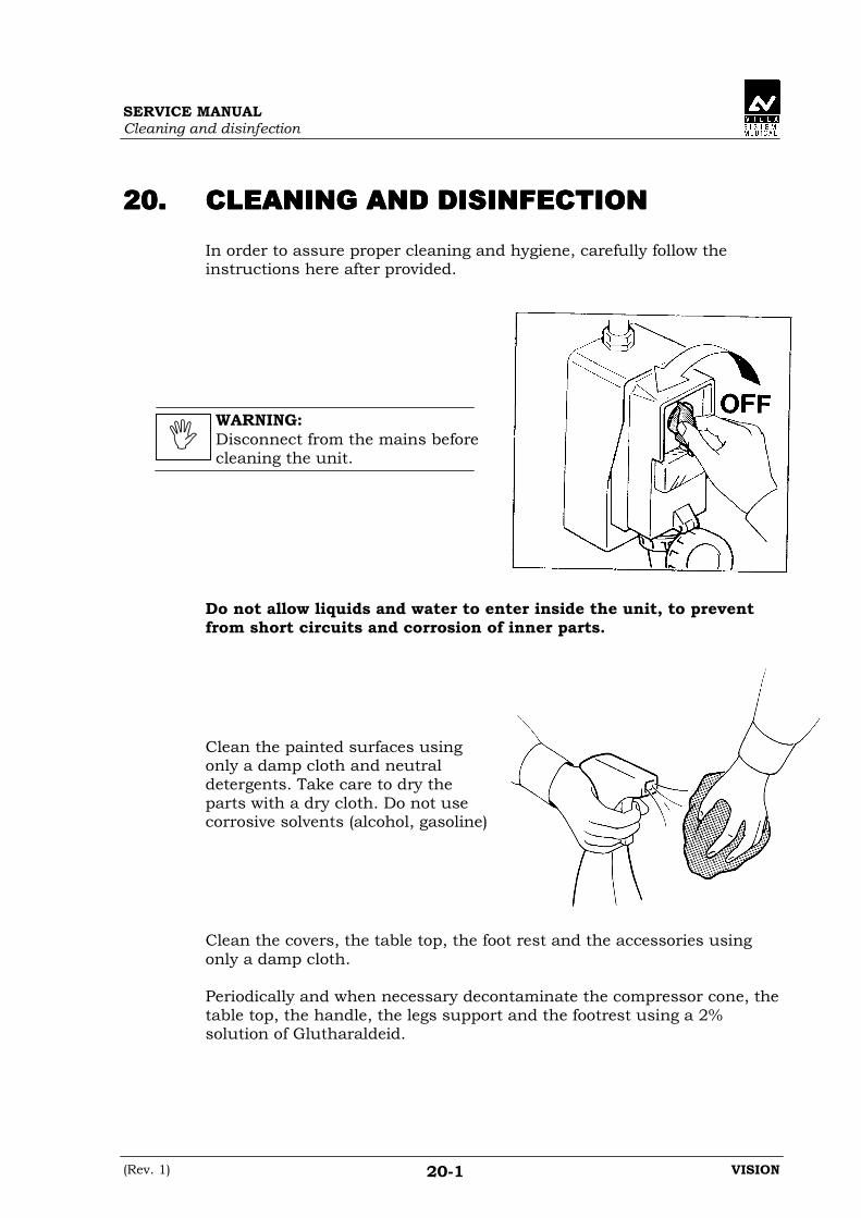
SERVICE MANUALCleaning and disinfection
(Rev. 1) VISION20-1
20.20.20.20. CLEANING AND DISINFECTIONCLEANING AND DISINFECTIONCLEANING AND DISINFECTIONCLEANING AND DISINFECTION
In order to assure proper cleaning and hygiene, carefully follow theinstructions here after provided.
WARNING:Disconnect from the mains beforecleaning the unit.
Do not allow liquids and water to enter inside the unit, to preventfrom short circuits and corrosion of inner parts.
Clean the painted surfaces usingonly a damp cloth and neutraldetergents. Take care to dry theparts with a dry cloth. Do not usecorrosive solvents (alcohol, gasoline)
Clean the covers, the table top, the foot rest and the accessories usingonly a damp cloth.
Periodically and when necessary decontaminate the compressor cone, thetable top, the handle, the legs support and the footrest using a 2%solution of Glutharaldeid.

SERVICE MANUALCleaning and disinfection
VISION (Rev. 1)20-2
THIS PAGE IS INTENTIONALLY LEFT BLANK
SERVICE MANUALMaintenance
(Rev. 1) VISION21-1
21.21.21.21. MAINTENANCEMAINTENANCEMAINTENANCEMAINTENANCE
21.121.121.121.1 Operator maintenanceOperator maintenanceOperator maintenanceOperator maintenance
As for all the electrical devices, in addition to proper use this unit alsorequires periodical checks and maintenance. This precautions will insurea safe and efficient performance of the device.
The preventive maintenance consists of checks that can be carried outdirectly by the operator as outlined in the following table.
Checks carried out by the operator.
Interval Type of check Method
Daily No residuals of organic or contrast liquids areleft on the device.
visual check
Once a week Check the integrity of the equipment. visual check
Once a month No friction is detected in the functionality ofmechanical components.Brakes functionality
visual check
Every 6 months Labels are present and not damaged visual check
WARNING:If there are doubts about the collimator correspondence between lightfield and X-ray field, the operator must contact VILLA SISTEMIMEDICALI S.p.a. authorised service centres.
WARNING:Metallic noise coming from the tube stand may indicate wearing of thecounterweight ropes. In this case stop using the unit immediately andcontact VILLA SISTEMI MEDICALI S.p.a. authorised service centres.
WARNING:If any of the above checks give negative results, the operator mustcontact VILLA SISTEMI MEDICALI S.p.a. authorised service centres.

SERVICE MANUALMaintenance
VISION (Rev. 1)21-2
21.221.221.221.2 Maintenance reserved to the authorised technicianMaintenance reserved to the authorised technicianMaintenance reserved to the authorised technicianMaintenance reserved to the authorised technician
The purpose of this manual is to provide the service technician with theinstructions for ensuring safe and efficient operation of the equipment.
In order to maintain intact the characteristics and quality level ofVISION, it is advisable to perform a general preventive maintenance by ahighly specialised service technician authorised by VILLA SISTEMIMEDICALI S.p.a..
WARNING:Any service operations must be performed exclusively by a specialisedtechnician authorised by VILLA SISTEMI MEDICALI S.p.a..
The maintenance operations performed by the specialised technicianmust be those described below, and must be carried out in the mannerdescribed.
Inspection or maintenance action Method
Disassemble the guards and clean the underlying parts,taking particular care with the Bucky if it is installed
visual check
Cleanness of the mylar under the patient support visual check
Cleanness of the serial changer visual check
Check centring of the beam see paragraph 17.2
Check the collimation see paragraph 17.2
Check the cassette format sub-division see paragraph 17.1
Check the functionality and motions actuated from thecontrol panel and from the keypad located on the tablecover
visual check
Check the centring of the tilting, along-table, across-table movements
visual check
Check the condition of the cables visual check
Check the chain tension visual check
Check the level of the lubricant in the reduction units visual check
Check the motor belts visual check
Check the condition of the motion bearings and guides visual check
Check the smoothness of the manual motions(transversal and compression)
direct test

SERVICE MANUALMaintenance
(Rev. 1) VISION21-3
WARNING:1. In case of replacement of parts or components, always use original
spare parts.The use of non original spare parts will void all warranties.Also, VILLA SISTEMI MEDICALI S.p.a. does not bear anyresponsibility if non-original spare parts are used and/or the serviceaction is performed by people not authorised by VILLA SISTEMIMEDICALI S.p.a. itself.
2. For cleaning and disinfecting operations, use only solvent-free liquidsand non abrasive materials.Take the utmost care to prevent the liquids from penetrating insidethe inaccessible parts of the equipment.Always disconnect the equipment from the electricity supply beforeperforming these operations.

SERVICE MANUALMaintenance
VISION (Rev. 1)21-4
THIS PAGE IS INTENTIONALLY LEFT BLANK

SERVICE MANUALSchematics and drawings
(Rev. 1) VISION22-1
22.22.22.22. SCHEMATICS AND DRAWINGSSCHEMATICS AND DRAWINGSSCHEMATICS AND DRAWINGSSCHEMATICS AND DRAWINGS
The circuitry of VISION utilises some connectors which are shown in theschematics of this chapter.
9, 15, 37 and 39 poles connectors are used on VISION.The 39 poles connector must be read as follows:
Pin number identification is shown in the next picture.
Example: 39poles connector Front view
Female Male
number in diagrams
connector number
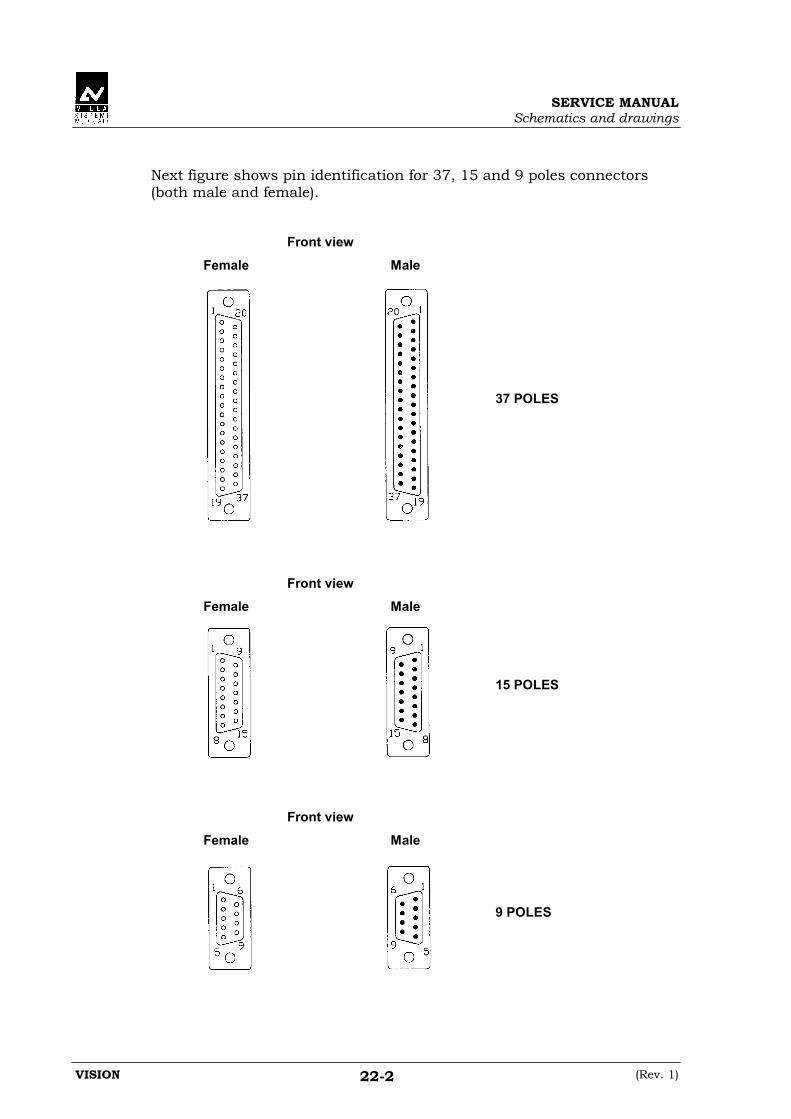
SERVICE MANUALSchematics and drawings
VISION (Rev. 1)22-2
Next figure shows pin identification for 37, 15 and 9 poles connectors(both male and female).
Front view
Female Male
Front view
Female Male
Front view
Female Male
37 POLES
15 POLES
9 POLES
SERVICE MANUALSchematics and drawings
(Rev. 1) VISION22-3
22.122.122.122.1 Schematics and drawings listSchematics and drawings listSchematics and drawings listSchematics and drawings list
1.1.1.1. General diagram
2.2.2.2. Table & Potter Bucky components layout
3.3.3.3. Spot Film Device (SFD) components layout
4.4.4.4. Collimator components layout
5.5.5.5. A13 Front panel push buttons board layout & schematic
6.6.6.6. Components plate layout
7.7.7.7. A12 Connectors board layout
8.8.8.8. A12 Connectors board schematic
9.9.9.9. A6 Interconnection board layout & schematic
10.10.10.10. Transformer plate layout
11.11.11.11. A14 Potter Bucky board layout
12.12.12.12. A1 SFD CPU board layout
13.13.13.13. A1 SFD CPU board schematic
14.14.14.14. A2 SFD Motor Driver board layout
15.15.15.15. A2 SFD Motor Driver board schematic
16.16.16.16. A4 SFD keyboard & display board layout
17.17.17.17. A4 SFD keyboard & display board schematic
18.18.18.18. A5 SFD joystick board layout
19.19.19.19. A5 SFD joystick board schematic

SERVICE MANUALSchematics and drawings
VISION (Rev. 1)22-4
20.20.20.20. A7 Prep. - Exposure board layoutA7 Prep. - Exposure board layoutA7 Prep. - Exposure board layoutA7 Prep. - Exposure board layout
21.21.21.21. A7 Prep. - Exposure board schematicA7 Prep. - Exposure board schematicA7 Prep. - Exposure board schematicA7 Prep. - Exposure board schematic
22.22.22.22. A11 Magnetic switch board layout & schematic (cm)A11 Magnetic switch board layout & schematic (cm)A11 Magnetic switch board layout & schematic (cm)A11 Magnetic switch board layout & schematic (cm)
23.23.23.23. A11 Magnetic switch board layout & schematic (inch)A11 Magnetic switch board layout & schematic (inch)A11 Magnetic switch board layout & schematic (inch)A11 Magnetic switch board layout & schematic (inch)
24.24.24.24. Autotransformer module layoutAutotransformer module layoutAutotransformer module layoutAutotransformer module layout
25.25.25.25. Autotransformer module schematicAutotransformer module schematicAutotransformer module schematicAutotransformer module schematic
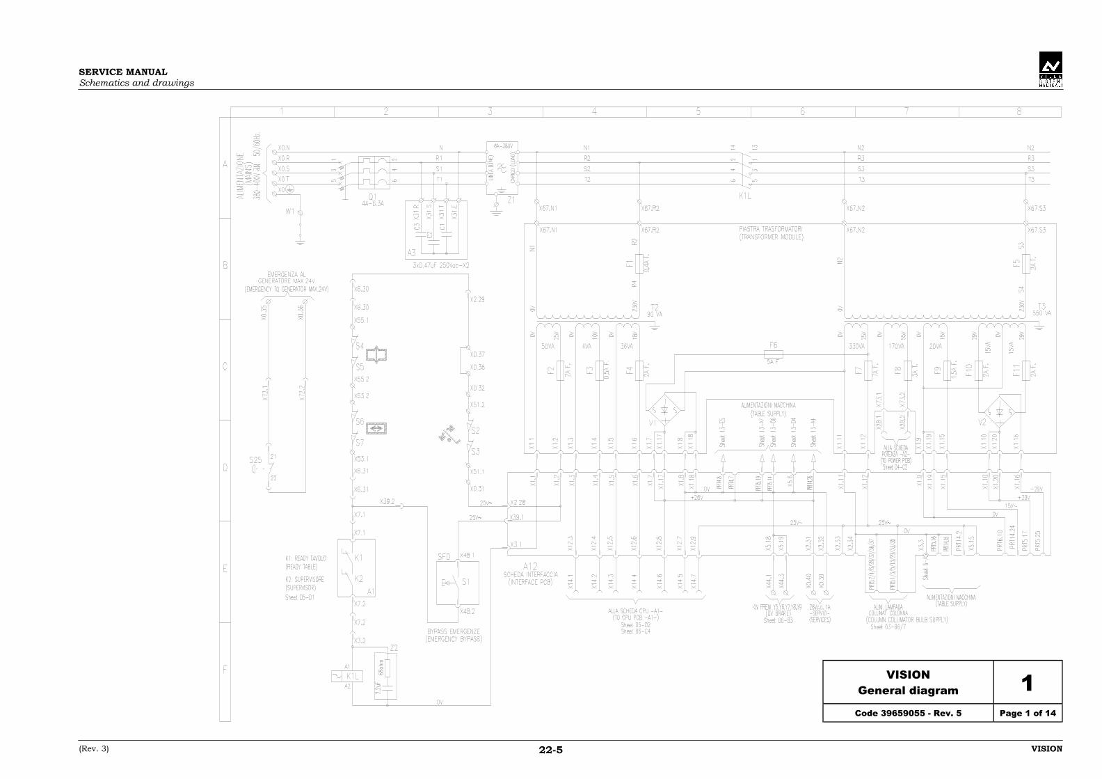
SERVICE MANUALSchematics and drawings
(Rev. 3) VISION22-5
VISIONGeneral diagram 1
Code 39659055 - Rev. 5 Page 1 of 14

SERVICE MANUALSchematics and drawings
(Rev. 3) VISION22-7
VISIONGeneral diagram 1
Code 39659055 - Rev. 5 Page 2 of 14

SERVICE MANUALSchematics and drawings
(Rev. 3) VISION22-9
VISIONGeneral diagram 1
Code 39659055 - Rev. 5 Page 3 of 14

SERVICE MANUALSchematics and drawings
(Rev. 3) VISION22-11
VISIONGeneral diagram 1
Code 39659055 - Rev. 5 Page 4 of 14

SERVICE MANUALSchematics and drawings
(Rev. 3) VISION22-13
VISIONGeneral diagram 1
Code 39659055 - Rev. 5 Page 5 of 14

SERVICE MANUALSchematics and drawings
(Rev. 3) VISION22-15
VISIONGeneral diagram 1
Code 39659055 - Rev. 5 Page 6 of 14

SERVICE MANUALSchematics and drawings
(Rev. 3) VISION22-17
VISIONGeneral diagram 1
Code 39659055 - Rev. 5 Page 7 of 14

SERVICE MANUALSchematics and drawings
(Rev. 3) VISION22-19
VISIONGeneral diagram 1
Code 39659055 - Rev. 5 Page 8 of 14

SERVICE MANUALSchematics and drawings
(Rev. 3) VISION22-21
VISIONGeneral diagram 1
Code 39659055 - Rev. 5 Page 9 of 14

SERVICE MANUALSchematics and drawings
(Rev. 3) VISION22-23
VISIONGeneral diagram 1
Code 39659055 - Rev. 5 Page 10 of 14

SERVICE MANUALSchematics and drawings
(Rev. 3) VISION22-25
VISIONGeneral diagram 1
Code 39659055 - Rev. 5 Page 11 of 14

SERVICE MANUALSchematics and drawings
(Rev. 3) VISION22-27
VISIONGeneral diagram 1
Code 39659055 - Rev. 5 Page 12 of 14

SERVICE MANUALSchematics and drawings
(Rev. 3) VISION22-29
VISIONGeneral diagram 1
Code 39659055 - Rev. 5 Page 13 of 14

SERVICE MANUALSchematics and drawings
(Rev. 3) VISION22-31
VISIONGeneral diagram 1
Code 39659055 - Rev. 5 Page 14 of 14
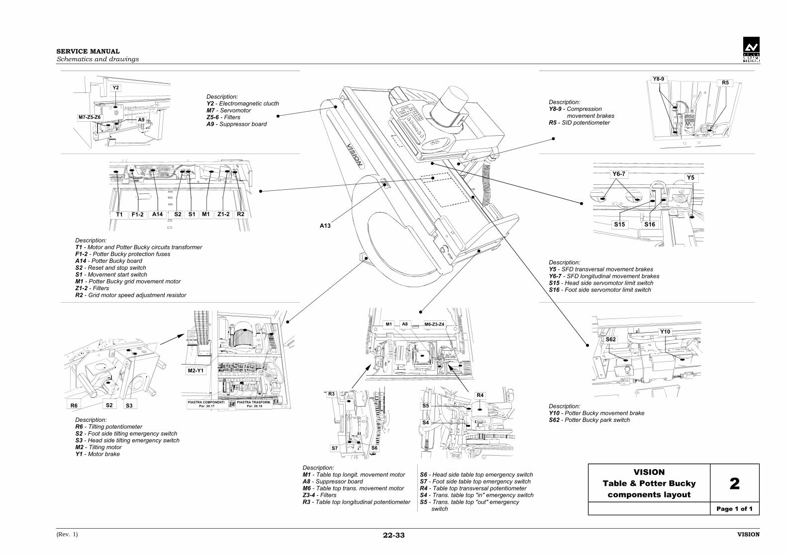
SERVICE MANUALSchematics and drawings
(Rev. 1) VISION22-33
Y2
A9M7-Z5-Z6
Description:Y2 - Electromagnetic clucthM7 - ServomotorZ5-6 - FiltersA9 - Suppressor board
Description:Y8-9 - Compression movement brakesR5 - SID potentiometer
Y8-9R5
T1 F1-2 A14 S2 S1 M1 Z1-2 R2
Description:T1 - Motor and Potter Bucky circuits transformerF1-2 - Potter Bucky protection fusesA14 - Potter Bucky boardS2 - Reset and stop switchS1 - Movement start switchM1 - Potter Bucky grid movement motorZ1-2 - FiltersR2 - Grid motor speed adjustment resistor
Y6-7Y5
S15 S16
Description:Y5 - SFD transversal movement brakesY6-7 - SFD longitudinal movement brakesS15 - Head side servomotor limit switchS16 - Foot side servomotor limit switch
S2 S3R6PIASTRA TRASFORM.
Par. 20.18PIASTRA COMPONENTI
Par. 20.17
M2-Y1
Description:R6 - Tilting potentiometerS2 - Foot side tilting emergency switchS3 - Head side tilting emergency switchM2 - Tilting motorY1 - Motor brake
M1 A8 M6-Z3-Z4
R3
S7 S6
S5
S4
R4
S62Y10
Description:Y10 - Potter Bucky movement brakeS62 - Potter Bucky park switch
Description:M1 - Table top longit. movement motorA8 - Suppressor boardM6 - Table top trans. movement motorZ3-4 - FiltersR3 - Table top longitudinal potentiometer
S6 - Head side table top emergency switchS7 - Foot side table top emergency switchR4 - Table top transversal potentiometerS4 - Trans. table top "in" emergency switchS5 - Trans. table top "out" emergency switch
VISIONTable & Potter Buckycomponents layout
2Page 1 of 1
A13

SERVICE MANUALSchematics and drawings
(Rev. 1) VISION22-35
M8 S13
Description:M8 - SFD grid movement motorS13 - Grid "zero position" switch
S10
Description:S10 - "SFD centered on X-ray" switch
S21
S11
S17
S20
Z16-17 M9
M4 M5
R1 R2
Description:M4 - SFD cassettes tray movement motorM5 - SFD shutters movement motorR1 - Cassette holder carriage potentiometerR2 - SFD shutters potentiometer
Description:S11 - Shutters initialisation "MIN" switchS17 - Shutters initialisation "MAX" switchS20 - "Close shutters" emergency switchS21 - "Open shutters" emergency switchZ16-17 - FiltersM9 - SFD compressor movement motor
S9
S8
Description:S8 - Compressor "IN" limit switchS9 - Compressor "OUT" limit switch
Description:S12 - Cassettes tray initialisation "MIN" switchS14 - Cassettes tray initialisation "MAX" switchS22 - Cassettes tray holder emergency switch
S14
S12
S22
VISIONSpot Film Device (SFD)
components layout3
Page 1 of 1
A4
A5
A7
A1
A2
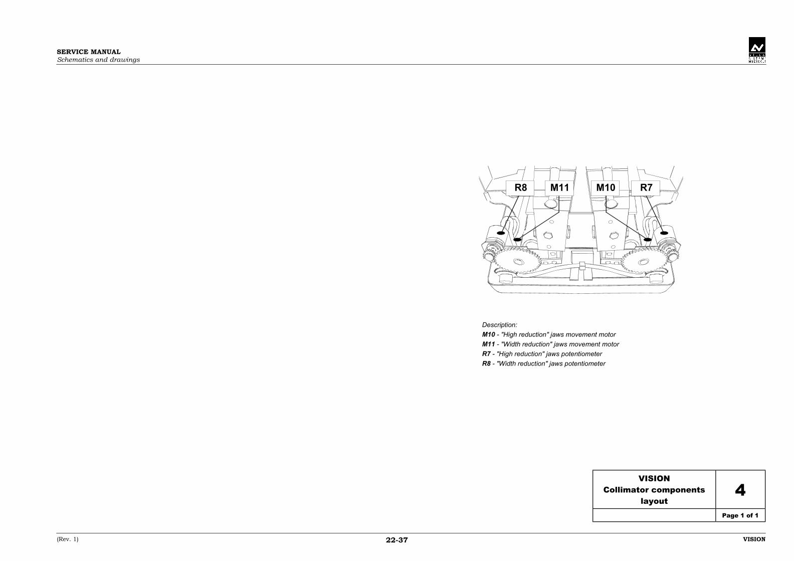
SERVICE MANUALSchematics and drawings
(Rev. 1) VISION22-37
R8 M11 M10 R7
Description:
M10 - "High reduction" jaws movement motor
M11 - "Width reduction" jaws movement motor
R7 - "High reduction" jaws potentiometer
R8 - "Width reduction" jaws potentiometer
VISIONCollimator components
layout4
Page 1 of 1

SERVICE MANUALSchematics and drawings
(Rev. 1) VISION22-39
VISIONA13 Front panel push buttons
board layout & schematic5
Code 58651678 - Rev. 0 Page 1 of 1

SERVICE MANUALSchematics and drawings
(Rev. 2) VISION22-41
VISIONComponent plate layout 6
Code 72651620 - Rev. 1 Page 1 of 1
NOTE:NOTE:NOTE:NOTE:For schematic, see drawing # 1(code 39659055)

SERVICE MANUALSchematics and drawings
(Rev. 1) VISION22-43
VISIONA12 connectors board
layout7
Code 58651597 - Rev. 0 Page 1 of 1
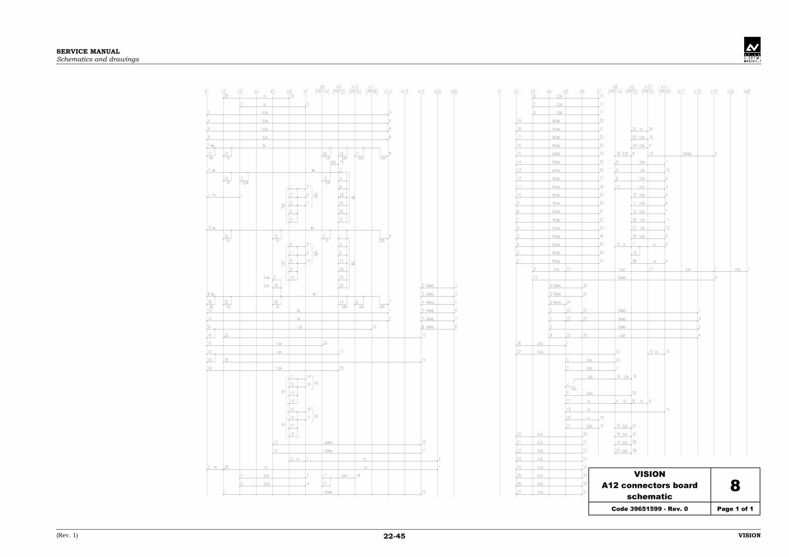
SERVICE MANUALSchematics and drawings
(Rev. 1) VISION22-45
VISIONA12 connectors board
schematic8
Code 39651599 - Rev. 0 Page 1 of 1

SERVICE MANUALSchematics and drawings
(Rev. 2) VISION22-47
VISIONA6 Interconnection board
layout & schematic9
Code 58651710 - Rev. 0 Page 1 of 1
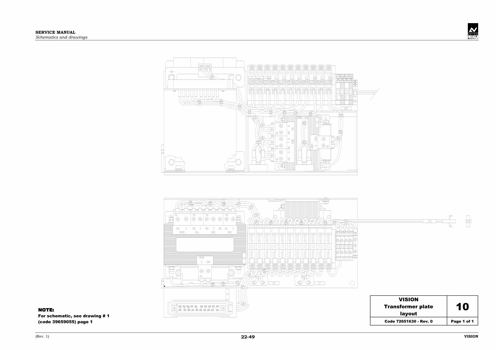
SERVICE MANUALSchematics and drawings
(Rev. 1) VISION22-49
VISIONTransformer plate
layout10
Code 72651630 - Rev. 0 Page 1 of 1
NOTE:NOTE:NOTE:NOTE:For schematic, see drawing # 1(code 39659055) page 1

SERVICE MANUALSchematics and drawings
(Rev. 3) VISION22-51
VISIONA14 Potter-Bucky board
layout11
Code 58201208 - Rev. 0 Page 1 of 1
NOTE:NOTE:NOTE:NOTE:For schematic, see drawing # 1(code 39659055) page 13
Voltage Jumper X4 Jumper X5
24 Vdc A - C120 Vac A - B A - B230 Vac A - B A - C

SERVICE MANUALSchematics and drawings
(Rev. 4) VISION22-53
VISIONA1 SFD CPU board layout 12
Code 58128110 - Rev. 2 Page 1 of 1

SERVICE MANUALSchematics and drawings
(Rev. 2) VISION22-55
VISIONA1 SFD CPU board schematic 13
Code 39129010 - Rev. 2 Page 1 of 16
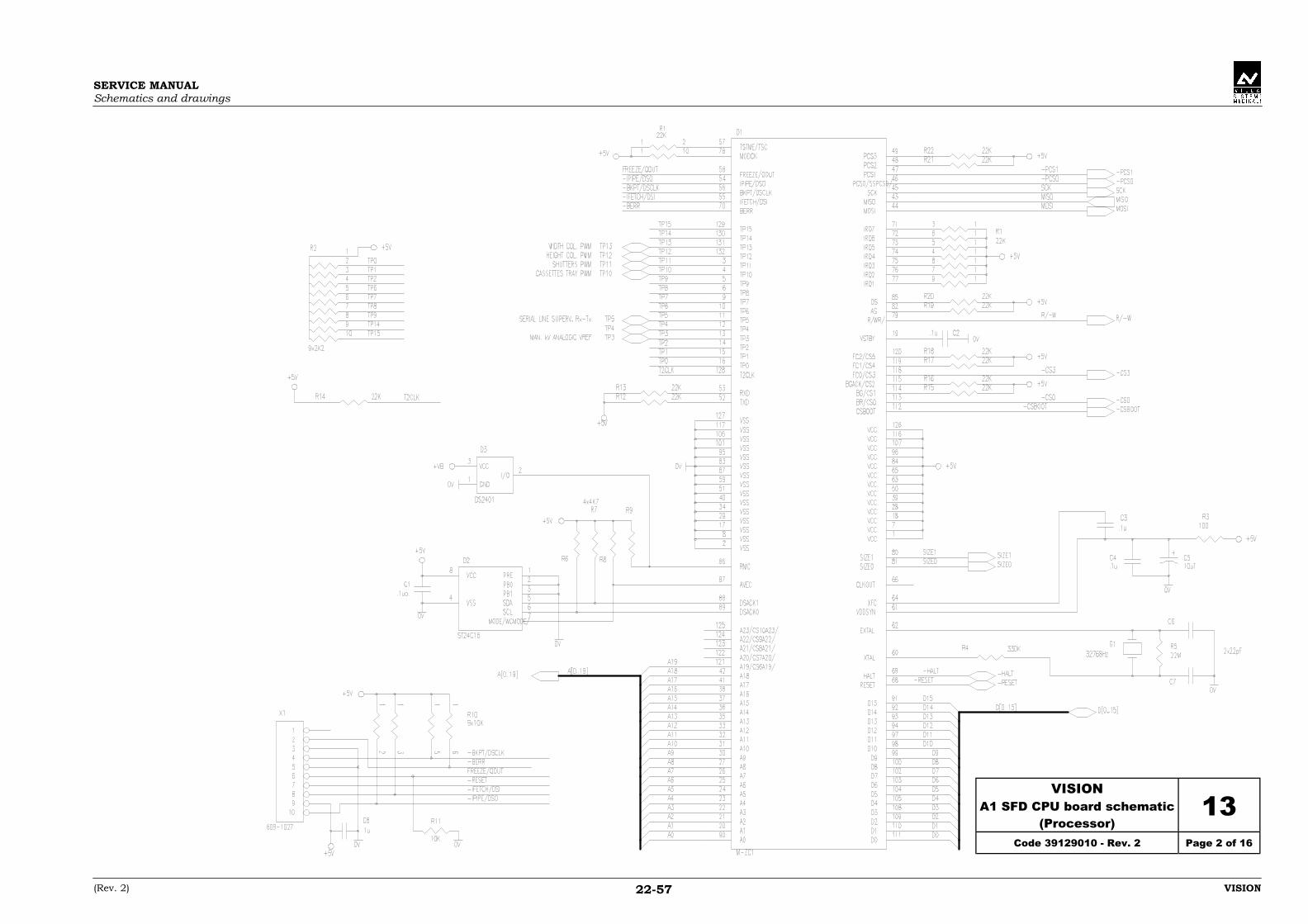
SERVICE MANUALSchematics and drawings
(Rev. 2) VISION22-57
VISIONA1 SFD CPU board schematic
(Processor)13
Code 39129010 - Rev. 2 Page 2 of 16
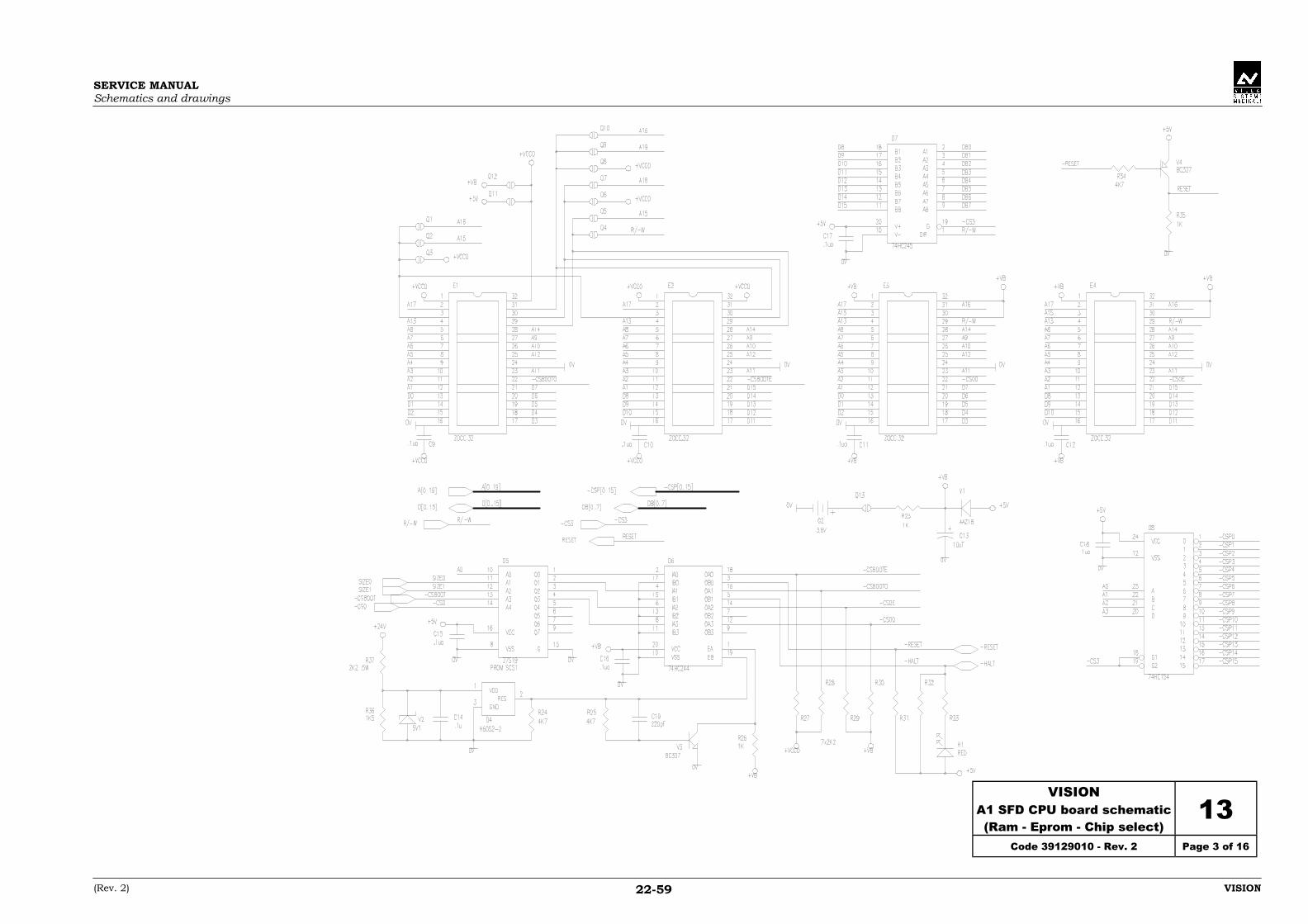
SERVICE MANUALSchematics and drawings
(Rev. 2) VISION22-59
VISIONA1 SFD CPU board schematic(Ram - Eprom - Chip select)
13Code 39129010 - Rev. 2 Page 3 of 16

SERVICE MANUALSchematics and drawings
(Rev. 2) VISION22-61
VISIONA1 SFD CPU board schematic
(Supervisor)13
Code 39129010 - Rev. 2 Page 4 of 16

SERVICE MANUALSchematics and drawings
(Rev. 2) VISION22-63
VISIONA1 SFD CPU board schematic
(Collimator driver)13
Code 39129010 - Rev. 2 Page 5 of 16

SERVICE MANUALSchematics and drawings
(Rev. 2) VISION22-65
VISIONA1 SFD CPU board schematic
(Potentiometers)13
Code 39129010 - Rev. 2 Page 6 of 16

SERVICE MANUALSchematics and drawings
(Rev. 2) VISION22-67
VISIONA1 SFD CPU board schematic
(Potentiometers)13
Code 39129010 - Rev. 2 Page 7 of 16

SERVICE MANUALSchematics and drawings
(Rev. 2) VISION22-69
VISIONA1 SFD CPU board schematic
(Input 1)13
Code 39129010 - Rev. 2 Page 8 of 16
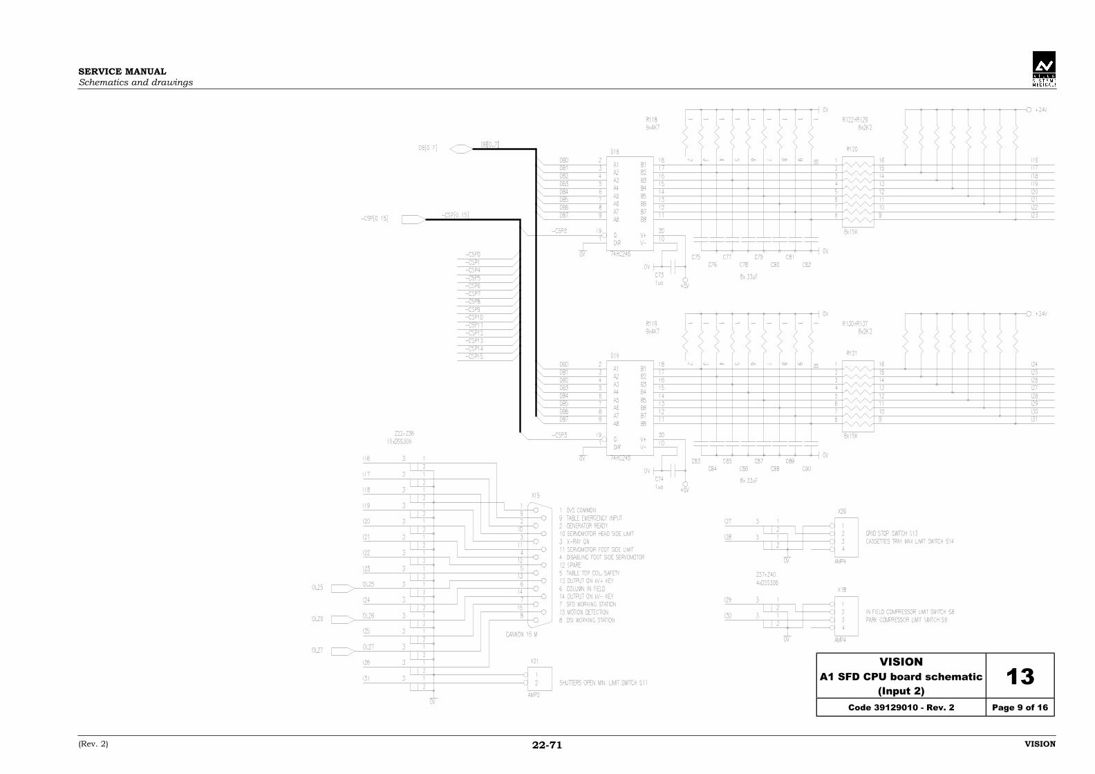
SERVICE MANUALSchematics and drawings
(Rev. 2) VISION22-71
VISIONA1 SFD CPU board schematic
(Input 2)13
Code 39129010 - Rev. 2 Page 9 of 16

SERVICE MANUALSchematics and drawings
(Rev. 2) VISION22-73
VISIONA1 SFD CPU board schematic
(Input 3)13
Code 39129010 - Rev. 2 Page 10 of 16

SERVICE MANUALSchematics and drawings
(Rev. 2) VISION22-75
VISIONA1 SFD CPU board schematic
(Output 1)13
Code 39129010 - Rev. 2 Page 11 of 16

SERVICE MANUALSchematics and drawings
(Rev. 2) VISION22-77
VISIONA1 SFD CPU board schematic
(Output 2)13
Code 39129010 - Rev. 2 Page 12 of 16
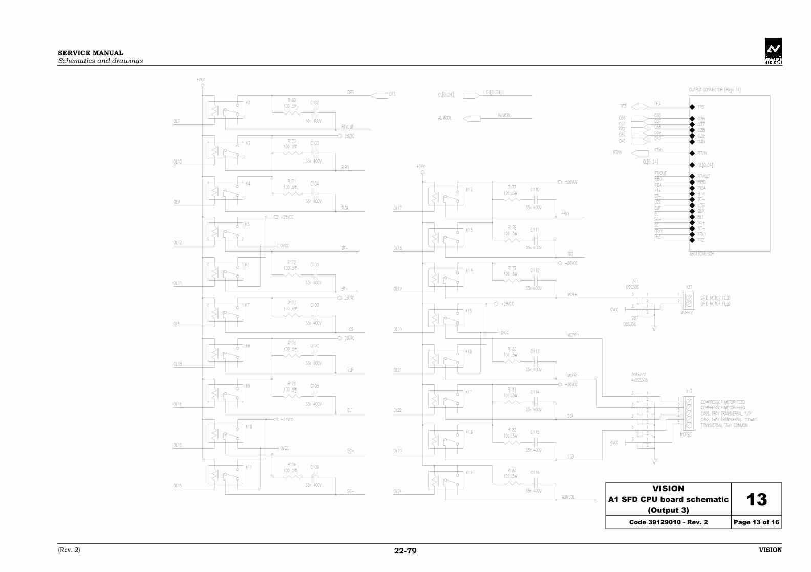
SERVICE MANUALSchematics and drawings
(Rev. 2) VISION22-79
VISIONA1 SFD CPU board schematic
(Output 3)13
Code 39129010 - Rev. 2 Page 13 of 16
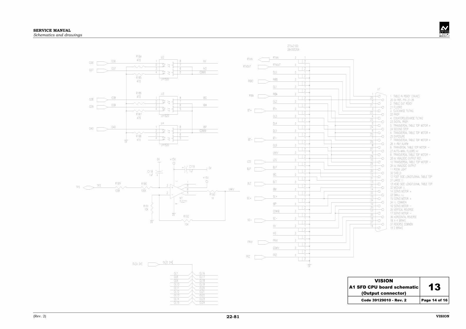
SERVICE MANUALSchematics and drawings
(Rev. 2) VISION22-81
VISIONA1 SFD CPU board schematic
(Output connector)13
Code 39129010 - Rev. 2 Page 14 of 16

SERVICE MANUALSchematics and drawings
(Rev. 2) VISION22-83
VISIONA1 SFD CPU board schematic
(Keyboard)13
Code 39129010 - Rev. 2 Page 15 of 16
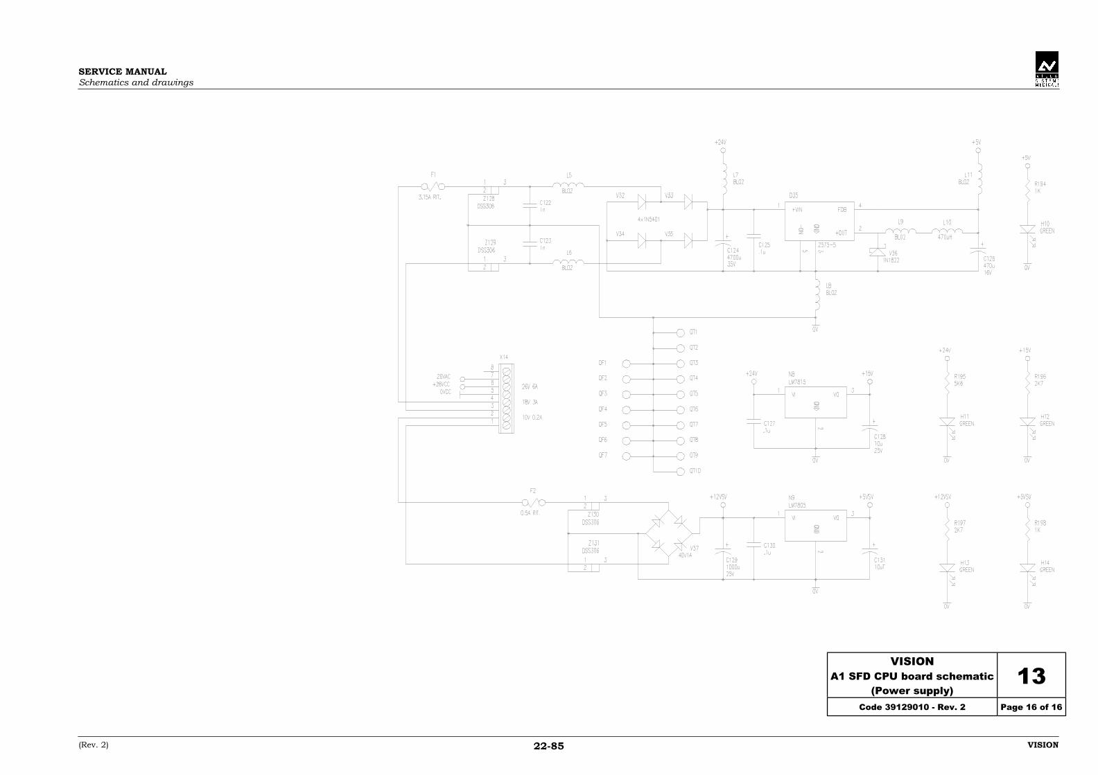
SERVICE MANUALSchematics and drawings
(Rev. 2) VISION22-85
VISIONA1 SFD CPU board schematic
(Power supply)13
Code 39129010 - Rev. 2 Page 16 of 16

SERVICE MANUALSchematics and drawings
(Rev. 1) VISION22-87
VISIONA2 SFD Motor Driver
board layout14
Code 58128105 - Rev. 1 Page 1 of 1

SERVICE MANUALSchematics and drawings
(Rev. 1) VISION22-89
VISIONA2 SFD Motor Driver
board schematic15
Code 39129012 - Rev. 2 Page 1 of 1

SERVICE MANUALSchematics and drawings
(Rev. 1) VISION22-91
VISIONA4 SFD keyboard &display board layout
16Code 58126110 - Rev. 0 Page 1 of 1

SERVICE MANUALSchematics and drawings
(Rev. 1) VISION22-93
VISIONA4 SFD keyboard &
display board schematic17
Code 39129011 - Rev. 0 Page 1 of 1

SERVICE MANUALSchematics and drawings
(Rev. 1) VISION22-95
VISIONA5 SFD joystick
board layout18
Code 58126112 - Rev. 0 Page 1 of 1

SERVICE MANUALSchematics and drawings
(Rev. 1) VISION22-97
VISIONA5 SFD joystickboard schematic
19Code 39129004 - Rev. 0 Page 1 of 1
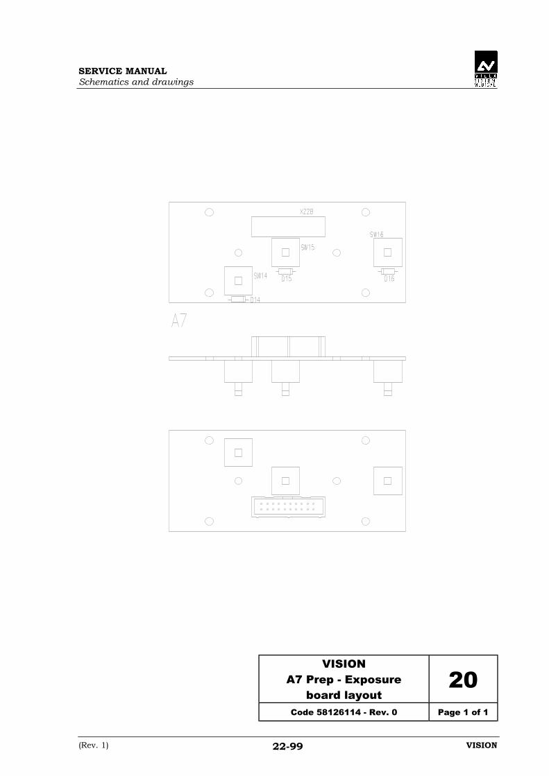
SERVICE MANUALSchematics and drawings
(Rev. 1) VISION22-99
VISIONA7 Prep - Exposure
board layout20
Code 58126114 - Rev. 0 Page 1 of 1
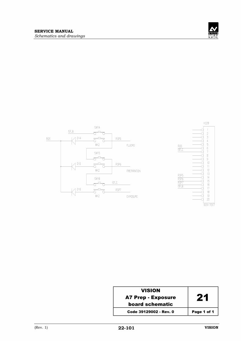
SERVICE MANUALSchematics and drawings
(Rev. 1) VISION22-101
VISIONA7 Prep - Exposureboard schematic
21Code 39129002 - Rev. 0 Page 1 of 1

SERVICE MANUALSchematics and drawings
(Rev. 2) VISION22-103
VISIONA11 Magnetic switch board
layout & schematic (cm)22
Code 58122110 - Rev. 1 Page 1 of 1

SERVICE MANUALSchematics and drawings
(Rev. 2) VISION22-105
VISIONA11 Magnetic switch boardlayout & schematic (inch)
23Code 58122108 - Rev. 1 Page 1 of 1

SERVICE MANUALSchematics and drawings
(Rev. 1) VISION22-107
For proper wiring (mains voltage setting),see drawings below
Set for 208V Set for 220V
Set for 415V Set for 480V
VISIONAutotransformer module
layout24
Page 1 of 1

SERVICE MANUALSchematics and drawings
(Rev. 1) VISION22-109
VISIONAutotransformer module
schematic25
Code 39659054 - Rev. 0 Page 1 of 1

Cod. 6965900703_Rev.4 0051
VILLA SISTEMI MEDICALI S.p.a.Via Delle Azalee, 320090 Buccinasco (MI) - ITALYTel. (+39) 02 48859.1Fax (+39) 02 4881844