Embed Size (px)
Citation preview
Unitronics 1
Vision™ OPLC™ V350-35-TR34 Installation Guide
The Unitronics V350-35-TR34 offers the following onboard I/Os: � 22 Digital Inputs, configurable via wiring to include 2 Analog and 3 HSC/Shaft-encoder Inputs � 8 Relay Outputs, 4 high-speed npn Transistor Outputs
General Description
V350 OPLCs are micro-OPLCs, rugged programmable logic controllers that comprise: � On-board I/O configuration � Built-in operating panel containing a 3.5” Color Touchscreen and programmable function keys
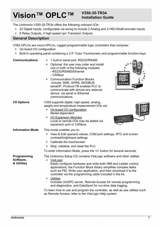
Communications � 1 built-in serial port: RS232/RS485 � Optional: the user may order and install
one or both of the following modules: - RS232/RS485/Ethernet - CANbus
� Communication Function Blocks include: SMS, GPRS, MODBUS serial/IP. Protocol FB enables PLC to communicate with almost any external device, via serial or Ethernet communications
I/O Options V350 supports digital, high-speed, analog, weight and temperature measurement I/Os via: � On-board I/O configuration
Model-dependent � I/O Expansion Modules
Local or remote I/Os may be added via expansion port or CANbus.
Information Mode This mode enables you to: � View & Edit operand values, COM port settings, RTC and screen
contrast/brightness settings � Calibrate the touchscreen � Stop, initialize, and reset the PLC
To enter Information Mode, press the <i> button for several seconds.
Programming Software, & Utilities
The Unitronics Setup CD contains VisiLogic software and other utilities � VisiLogic
Easily configure hardware and write both HMI and Ladder control applications; the Function Block library simplifies complex tasks such as PID. Write your application, and then download it to the controller via the programming cable included in the kit.
� UtilitiesIncludes UniOPC server, Remote Access for remote programming and diagnostics, and DataXport for run-time data logging.
To learn how to use and program the controller, as well as use utilities such as Remote Access, refer to the VisiLogic Help system.
V350-35-TR34 Installation Guide
2 Unitronics
Removable Memory Storage
Micro SD card: store datalogs, Alarms, Trends, Data Tables; export to Excel; backup Ladder, HMI & OS and use this data to ‘clone’ PLCs. For more data, refer to the SD topics in the VisiLogic Help system.
Data Tables Data tables enable you to set recipe parameters and create datalogs. Additional product documentation is in the Technical Library, located at www.unitronics.com, and on the Unitronics’ Setup CD. Technical support is available at the site, and from [email protected].
Standard Kit Contents Vision controller Mounting brackets (x2) I/O connectors (x2) Rubber seal Battery (installed) 2 sets of key label slides Programming cable + RS232 adapter Unitronics’ Setup CD
Danger Symbols When any of the following symbols appear, read the associated information carefully.
Symbol Meaning Description
Danger The identified danger causes physical and property damage.
Warning The identified danger could cause physical and property damage.
Caution Caution Use caution. � Before using this product, the user must read and understand this document. � All examples and diagrams are intended to aid understanding, and do not guarantee operation.
Unitronics accepts no responsibility for actual use of this product based on these examples. � Please dispose of this product according to local and national standards and regulations. � Only qualified service personnel should open this device or carry out repairs.
Failure to comply with appropriate safety guidelines can cause severe injury or property damage.
� Do not attempt to use this device with parameters that exceed permissible levels. � To avoid damaging the system, do not connect/disconnect the device when power is on.
Environmental Considerations
� Do not install in areas with: excessive or conductive dust, corrosive or flammable gas, moisture or rain, excessive heat, regular impact shocks or excessive vibration, in accordance with the standards given in the product’s technical specification sheet.
� Ventilation: 10mm space required between controller’s top/bottom edges & enclosure walls. � Do not place in water or let water leak onto the unit. � Do not allow debris to fall inside the unit during installation. � Install at maximum distance from high-voltage cables and power equipment.
Vision™ OPLC™
Unitronics 3
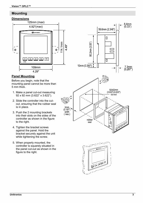
Mounting Dimensions
Panel MountingBefore you begin, note that the mounting panel cannot be more than 5 mm thick.
1. Make a panel cut-out measuring 92 x 92 mm (3.622” x 3.622”).
2. Slide the controller into the cut-out, ensuring that the rubber seal is in place.
3. Push the 2 mounting brackets into their slots on the sides of the controller as shown in the figure to the right.
4. Tighten the bracket screws against the panel. Hold the bracket securely against the unit while tightening the screw.
5. When properly mounted, the controller is squarely situated in the panel cut-out as shown in the figure to the right.
V350-35-TR34 Installation Guide
4 Unitronics
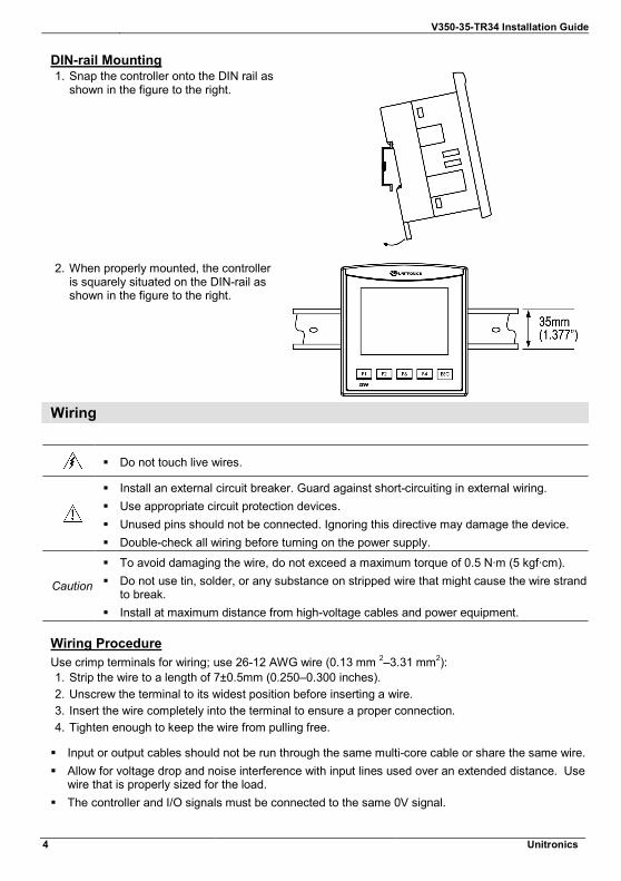
DIN-rail Mounting1. Snap the controller onto the DIN rail as
shown in the figure to the right.
2. When properly mounted, the controller is squarely situated on the DIN-rail as shown in the figure to the right.
Wiring
� Do not touch live wires.
� Install an external circuit breaker. Guard against short-circuiting in external wiring. � Use appropriate circuit protection devices. � Unused pins should not be connected. Ignoring this directive may damage the device. � Double-check all wiring before turning on the power supply.
Caution
� To avoid damaging the wire, do not exceed a maximum torque of 0.5 N·m (5 kgf·cm). � Do not use tin, solder, or any substance on stripped wire that might cause the wire strand
to break. � Install at maximum distance from high-voltage cables and power equipment.
Wiring ProcedureUse crimp terminals for wiring; use 26-12 AWG wire (0.13 mm 2–3.31 mm2): 1. Strip the wire to a length of 7±0.5mm (0.250–0.300 inches). 2. Unscrew the terminal to its widest position before inserting a wire. 3. Insert the wire completely into the terminal to ensure a proper connection. 4. Tighten enough to keep the wire from pulling free.
� Input or output cables should not be run through the same multi-core cable or share the same wire.� Allow for voltage drop and noise interference with input lines used over an extended distance. Use
wire that is properly sized for the load. � The controller and I/O signals must be connected to the same 0V signal.
Vision™ OPLC™
Unitronics 5
I/Os This model comprises a total of 22 inputs and 8 relay, 4 npn outputs. Input functionality can be adapted as follows: 1. 22 inputs may be used as digital inputs. They may be wired, in a group, and set to either
npn or pnp via a single jumper. In addition, according to jumper settings and appropriate wiring:
- Inputs 14 and 15 can function as either digital or analog inputs. - Inputs 0, 2, and 4 can function as high-speed counters, as part of a shaft-encoder,
or as normal digital inputs. - Inputs 1, 3, and 5 can function as either counter reset, as part of a shaft-encoder,
or as normal digital inputs. - If inputs 0, 2 and 4 are set as high-speed counters (without reset), inputs 1, 3 and 5
can function as normal digital inputs.
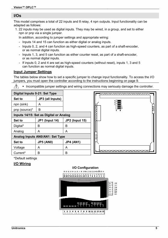
Input Jumper SettingsThe tables below show how to set a specific jumper to change input functionality. To access the I/O jumpers, you must open the controller according to the instructions beginning on page 9.
� Incompatible jumper settings and wiring connections may seriously damage the controller.
Digital Inputs 0-21: Set Type
Set to JP3 (all Inputs) npn (sink) A
pnp (source)* B Inputs 14/15: Set as Digital or Analog Set to JP1 (Input 14) JP2 (Input 15) Digital* B B
Analog A A Analog Inputs AN0/AN1: Set Type Set to JP5 (AN0) JP4 (AN1) Voltage A A
Current* B B
*Default settings
I/O WiringI/O Configuration
V350-35-TR34 Installation Guide
6 Unitronics
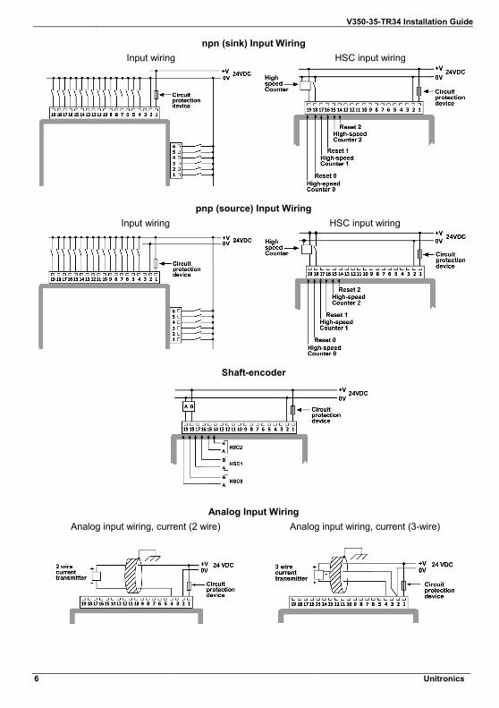
npn (sink) Input Wiring Input wiring HSC input wiring
pnp (source) Input Wiring Input wiring HSC input wiring
Shaft-encoder
Analog Input Wiring Analog input wiring, current (2 wire) Analog input wiring, current (3-wire)
Vision™ OPLC™
Unitronics 7
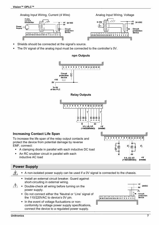
Analog Input Wiring, Current (4 Wire) Analog Input Wiring, Voltage
� Shields should be connected at the signal’s source. � The 0V signal of the analog input must be connected to the controller’s 0V.
npn Outputs
Relay Outputs
Increasing Contact Life Span To increase the life span of the relay output contacts and protect the device from potential damage by reverse EMF, connect: � A clamping diode in parallel with each inductive DC load � An RC snubber circuit in parallel with each
inductive AC load
Power Supply � A non-isolated power supply can be used if a 0V signal is connected to the chassis.
� Install an external circuit breaker. Guard against short-circuiting in external wiring.
� Double-check all wiring before turning on the power supply.
� Do not connect either the ‘Neutral or ‘Line’ signal of the 110/220VAC to device’s 0V pin.
� In the event of voltage fluctuations or non-conformity to voltage power supply specifications, connect the device to a regulated power supply.
V350-35-TR34 Installation Guide
8 Unitronics
Earthing the Power Supply To maximize system performance, avoid electromagnetic interference by: � Mounting the controller on a metal panel. � Earthing the controller’s power supply: connect one end of a 14 AWG wire to the chassis
signal; connect the other end to the panel. Note: If possible, the wire used to earth the power supply should not exceed 10 cm in length. However, it is recommended to earth the controller in all cases.
Communication Port
� Turn off power before making communications connections.
Caution
� Signals are related to the controller’s 0V; the same 0V is used by the power supply. � Always use the appropriate port adapters. � The serial port is not isolated. If the controller is used with a non-isolated external
device, avoid potential voltage that exceeds ± 10V.
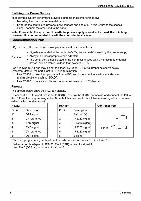
Port 1 is type RJ-11 and may be set to either RS232 or RS485 via jumper as shown below. By factory default, the port is set to RS232, termination ON. � Use RS232 to download programs from a PC, and to communicate with serial devices
and applications, such as SCADA. � Use RS485 to create a multi-drop network containing up to 32 devices.
PinoutsThe pinouts below show the PLC port signals. To connect a PC to a port that is set to RS485, remove the RS485 connector, and connect the PC to the PLC via the programming cable. Note that this is possible only if flow control signals are not used (which is the standard case).
RS232 RS485** Controller Port Pin # Description Pin # Description 1* DTR signal 1 A signal (+) 2 0V reference 2 (RS232 signal) 3 TXD signal 3 (RS232 signal) 4 RXD signal 4 (RS232 signal) 5 0V reference 5 (RS232 signal) 6* DSR signal 6 B signal (-)
Pin #1
*Standard programming cables do not provide connection points for pins 1 and 6. **When a port is adapted to RS485, Pin 1 (DTR) is used for signal A, and Pin 6 (DSR) signal is used for signal B.
Vision™ OPLC™
Unitronics 9
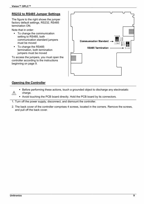
RS232 to RS485 Jumper Settings
The figure to the right shows the jumper factory default settings, RS232, RS485 termination ON. Note that in order: � To change the communication
setting to RS485, both communication standard jumpers must be moved
� To change the RS485 termination, both termination jumpers must be moved
To access the jumpers, you must open the controller according to the instructions beginning on page 9.
Opening the Controller
� Before performing these actions, touch a grounded object to discharge any electrostatic charge.
� Avoid touching the PCB board directly. Hold the PCB board by its connectors.
1. Turn off the power supply, disconnect, and dismount the controller.
2. The back cover of the controller comprises 4 screws, located in the corners. Remove the screws, and pull off the back cover.
V350-35-TR34 Installation Guide
10 Unitronics
Changing I/O Settings1. The I/O board of the controller is now exposed, enabling you to change I/O settings according to
the jumpers shown on page 5.
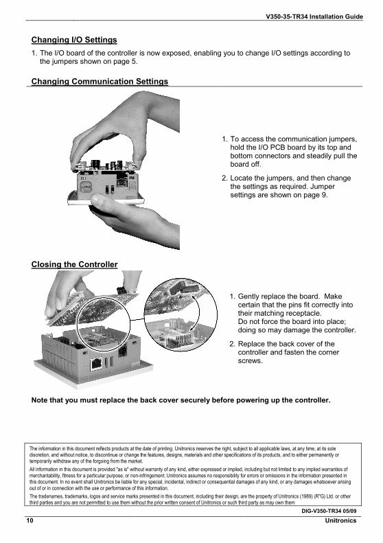
Changing Communication Settings
1. To access the communication jumpers, hold the I/O PCB board by its top and bottom connectors and steadily pull the board off.
2. Locate the jumpers, and then change the settings as required. Jumper settings are shown on page 9.
Closing the Controller
1. Gently replace the board. Make certain that the pins fit correctly into their matching receptacle. Do not force the board into place; doing so may damage the controller.
2. Replace the back cover of the controller and fasten the corner screws.
Note that you must replace the back cover securely before powering up the controller.
The information in this document reflects products at the date of printing. Unitronics reserves the right, subject to all applicable laws, at any time, at its sole discretion, and without notice, to discontinue or change the features, designs, materials and other specifications of its products, and to either permanently or temporarily withdraw any of the forgoing from the market. All information in this document is provided "as is" without warranty of any kind, either expressed or implied, including but not limited to any implied warranties of merchantability, fitness for a particular purpose, or non-infringement. Unitronics assumes no responsibility for errors or omissions in the information presented in this document. In no event shall Unitronics be liable for any special, incidental, indirect or consequential damages of any kind, or any damages whatsoever arising out of or in connection with the use or performance of this information. The tradenames, trademarks, logos and service marks presented in this document, including their design, are the property of Unitronics (1989) (R"G) Ltd. or other third parties and you are not permitted to use them without the prior written consent of Unitronics or such third party as may own them
DIG-V350-TR34 05/09