Embed Size (px)
Citation preview
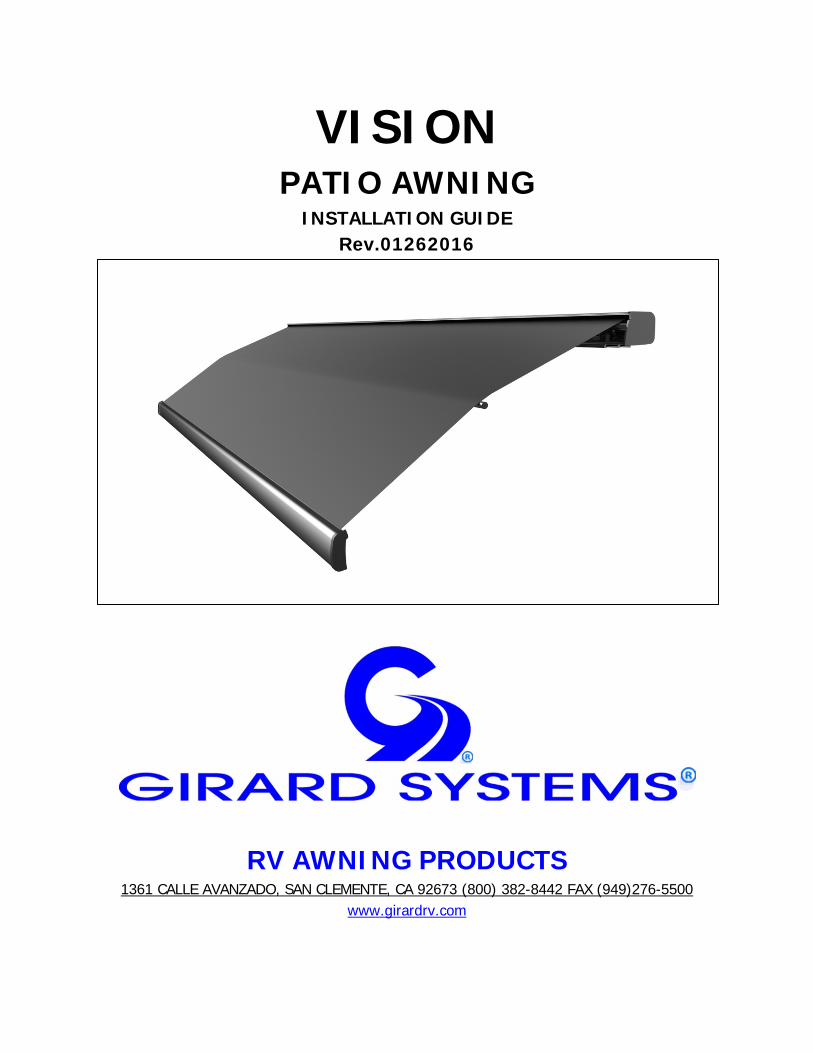
VISION PATIO AWNING
INSTALLATION GUIDE Rev.01262016
RV AWNING PRODUCTS 1361 CALLE AVANZADO, SAN CLEMENTE, CA 92673 (800) 382-8442 FAX (949)276-5500
www.girardrv.com
Page 2 of 25
AWNINGS FITTED TO THIS VEHICLE;
MODEL _____________________________ SERIAL No. ______________________
MODEL _____________________________ SERIAL No. ______________________
MODEL _____________________________ SERIAL No. ______________________
MODEL _____________________________ SERIAL No. ______________________
Page 3 of 25
ALL ELECTRICAL WORK MUST BE CARRIED OUT BY QUALIFIED PERSONNEL AND CONFORM TO APPLICABLE ELECTRICAL CODES AND STANDARDS.
• Turn off power before beginning any electrical work. • Please consult your RV’s wiring diagram to locate any wiring
prior to any drilling or any installation procedures. • Ensure that placement of controls, cables, and wires are not
in any way obstructed. This can damage the components and obstruct electrical current.
• Use only certified components.
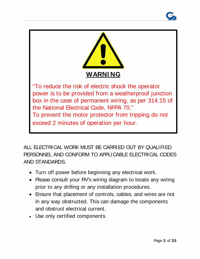
WARNING
“To reduce the risk of electric shock the operator power is to be provided from a weatherproof junction box in the case of permanent wiring, as per 314.15 of the National Electrical Code, NFPA 70.” To prevent the motor protector from tripping do not exceed 2 minutes of operation per hour.

Page 4 of 25
Girard Systems awnings may be operated in light wind and rain conditions. When periods of heavy rain and or high wind are expected the awning must be closed. Never leave the Awning open and unattended. Damage caused by wind and rain is not covered by warranty. All awnings must be closed prior to moving the vehicle for any reason. As an extra safety precaution a visual check that every awning is fully closed is required. Damage caused by failure to comply with these instructions is not covered by warranty. Before using your awning, ensure that the area into which the awning will be deployed is free of obstructions (Trees, walls, pillars, posts, other vehicles etc.) Damage caused by collisions with any of the above or similar is not covered by warranty. Before using your awning make sure that all of your electrical circuits are operating correctly. Recreational Vehicles can generate AC power from three separate sources. The electrical system transfer switch in your vehicle will select power for the awning as follows: Shore Power – if connected; Generator Power – if the generator is running; Inverter Power – batteries must be charged for inverter operation. Girard Systems awnings are supplied with an electric motor appropriate to the product.
Page 5 of 25
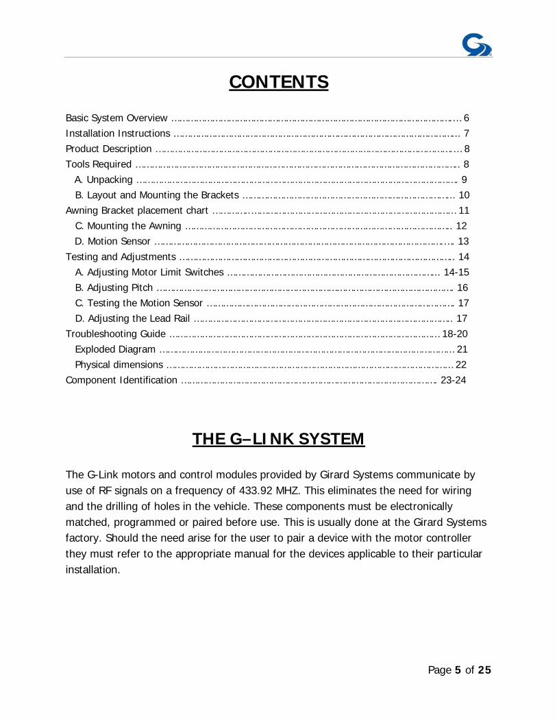
CONTENTS Basic System Overview ………………………………………………………………………………………….… 6 Installation Instructions …………………………………………………………………………………………... 7 Product Description ……………………………………………………………………………………………….… 8 Tools Required ……………………………………………………………………………………………………….. 8 A. Unpacking ………………………………………………………………………………………………………. 9 B. Layout and Mounting the Brackets …………………………………………………………………... 10 Awning Bracket placement chart …………..………………………………………………………………… 11 C. Mounting the Awning …………………………………………………………………………………….. 12 D. Motion Sensor …………………………………………………………………………………………….…. 13 Testing and Adjustments ……………………………………………………………………………………….. 14 A. Adjusting Motor Limit Switches …………………………………………………………………... 14-15 B. Adjusting Pitch ………………………………………………………………………………………………. 16 C. Testing the Motion Sensor ………………………………………………………………………………. 17 D. Adjusting the Lead Rail ………………………………………………………………………………….. 17 Troubleshooting Guide ……………………………………………………………………………………… 18-20 Exploded Diagram ……………………………………………………………………………………………… 21 Physical dimensions …………………………………………………………………………………………… 22 Component Identification …………………………………………………………………………………. 23-24
THE G–LINK SYSTEM
The G-Link motors and control modules provided by Girard Systems communicate by use of RF signals on a frequency of 433.92 MHZ. This eliminates the need for wiring and the drilling of holes in the vehicle. These components must be electronically matched, programmed or paired before use. This is usually done at the Girard Systems factory. Should the need arise for the user to pair a device with the motor controller they must refer to the appropriate manual for the devices applicable to their particular installation.

Page 6 of 25
BASIC SYSTEM OVERVIEW
The VISION Awning consists of three main components:
1. Mechanical system – consisting of: • The enclosure (or cassette) protects the awning while closed. • The roller tube which is mounted within the cassette. • The top cover or fabric rolled onto the roller tube and connected to the lead
rail that extends from the enclosure when the awning is opened. • The folding arms that supports the lead rail and the fabric. • The tubular motor which is mounted inside of the roller tube that controls the
extension and retraction of the awning. 2. Electronic controls – to power and operate the motor:
G-Links Electronics Kit: 98GCK-18
• 98GC136 – 110V Motor controller • 98GC779G – 12V Motion Sensor • 98GC230 – 2 Channel, wireless wall switch. • 98GC105A – 5 Channel, wireless handheld remote.
Please refer to the 98GCK-18 instructions/ programming guide with any questions regarding these electronic components.
Page 7 of 25
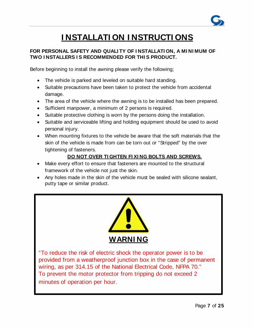
INSTALLATION INSTRUCTIONS
FOR PERSONAL SAFETY AND QUALITY OF INSTALLATION, A MINIMUM OF TWO INSTALLERS IS RECOMMENDED FOR THIS PRODUCT. Before beginning to install the awning please verify the following;
• The vehicle is parked and leveled on suitable hard standing. • Suitable precautions have been taken to protect the vehicle from accidental
damage. • The area of the vehicle where the awning is to be installed has been prepared. • Sufficient manpower, a minimum of 2 persons is required. • Suitable protective clothing is worn by the persons doing the installation. • Suitable and serviceable lifting and holding equipment should be used to avoid
personal injury. • When mounting fixtures to the vehicle be aware that the soft materials that the
skin of the vehicle is made from can be torn out or “Stripped” by the over tightening of fasteners.
DO NOT OVER TIGHTEN FIXING BOLTS AND SCREWS. • Make every effort to ensure that fasteners are mounted to the structural
framework of the vehicle not just the skin. • Any holes made in the skin of the vehicle must be sealed with silicone sealant,
putty tape or similar product.
WARNING
“To reduce the risk of electric shock the operator power is to be provided from a weatherproof junction box in the case of permanent wiring, as per 314.15 of the National Electrical Code, NFPA 70.” To prevent the motor protector from tripping do not exceed 2 minutes of operation per hour.
Page 8 of 25
PRODUCT DESCRIPTION The VISION is a dual pitch awning system provides protection from the sun at a touch of a button. The VISION awning is built to your specifications with the highest quality materials available, your unit features:
• A standard motor that operates with a wireless motor controller or a wireless motor that operates with an integrated motor control.
• Motion Sensor that will retract the awning to prevent damage from the wind.
• A hand held Remote Control • A wall mounted Remote Switch • Options include; electronic automation controls to ensure proper closing at
all times, a control to retract all awnings when the vehicles’ motor is started, and more….
TOOLS REQUIRED
• Electric Drill • Tape measure • (2) ladders • Chalk line • Flat head screwdriver (small) • Phillips screwdriver • Caulking gun • (2) tubes silicone caulking • Drill bits: 1/8”, 3/8”, and 7/16” • Open-end wrenches: 13mm (1/2”), 17mm and 19mm. • Keyhole saw

Page 9 of 25
A. UNPACKING Before starting any of the installation procedures:
1. Unpack the awning and inspect the product for any possible damage that may have occurred during shipping.
2. Ensure that the length and motor placement of your awning are correct. 3. When you have determined that the product is to your satisfaction, remove
the mounting brackets and place the awning in a safe location while preparing the RV. a. To remove the brackets locate the slide lock that retains the bracket to
the housing. (Figure 1) b. Using a 13mm or ½” wrench, loosen all set screws on the slide locks. c. Once the set screws have been loosened the slide locks should slide
freely, clear the slide lock away from the bracket. 4. If you have discovered any damage or missing parts please contact your
supplier.
Figure 1
SLIDE LOCK
SET SCREW
MOUNTING BRACKET
Page 10 of 25
B. LAYOUT AND MOUNTING THE BRACKETS
1. MOUNTING THE AWNING – NOTE: The clearances needed for mounting the VISION varies by manufacturer. The shape of the roof, the depth of installation and all other factors should be taken into consideration when installing this product. Please consult Girard Systems if there are any questions regarding your installation. a. Determine the exact position for the final installation of the awning.
b. Mounting brackets must be installed within 6” of the ends of the awning.
Once you have determined the location of the two end brackets snap a chalk line between the two points to ensure alignment of the installation. You will be able to reference this line to install the smaller middle brackets at a later time.
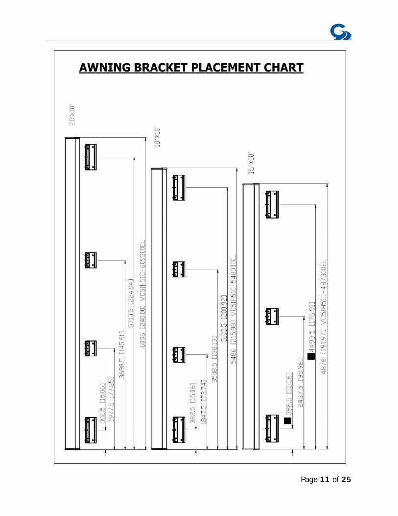
c. To find the location of the smaller middle brackets please refer to the chart on the following page. NOTE: The placement of the middle brackets must comply with the AWNING BRACKET PLACEMENT CHART. Failure to follow these instructions will void the warranty of this product.
d. Now that you have determined the bracket locations, using the bracket as your template, mark the holes for mounting the bracket.
e. Fix the brackets to the roof of the vehicle using appropriate sized fasteners.
NOTE: It is up to the installer to find adequate structure to securely fasten the mounting brackets to. All caution must be taken to weather seal all installation perforations. Failure to do this could result in damage to the vehicle. NOTE: Please consult your RV’s wiring diagram to ensure that no wiring will be damaged while drilling any holes.
Page 11 of 25
Page 12 of 25
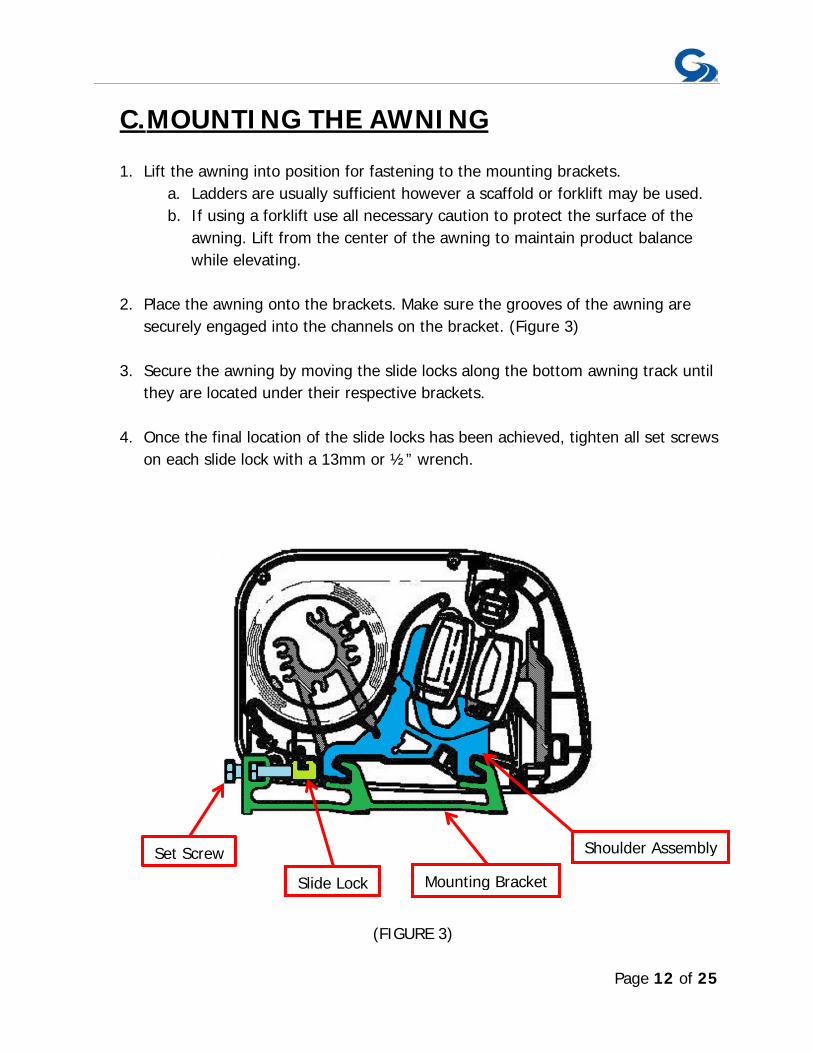
C. MOUNTING THE AWNING
1. Lift the awning into position for fastening to the mounting brackets. a. Ladders are usually sufficient however a scaffold or forklift may be used. b. If using a forklift use all necessary caution to protect the surface of the
awning. Lift from the center of the awning to maintain product balance while elevating.
2. Place the awning onto the brackets. Make sure the grooves of the awning are securely engaged into the channels on the bracket. (Figure 3)
3. Secure the awning by moving the slide locks along the bottom awning track until they are located under their respective brackets.
4. Once the final location of the slide locks has been achieved, tighten all set screws
on each slide lock with a 13mm or ½” wrench.
(FIGURE 3)
Shoulder Assembly
Mounting Bracket Slide Lock
Set Screw
Page 13 of 25
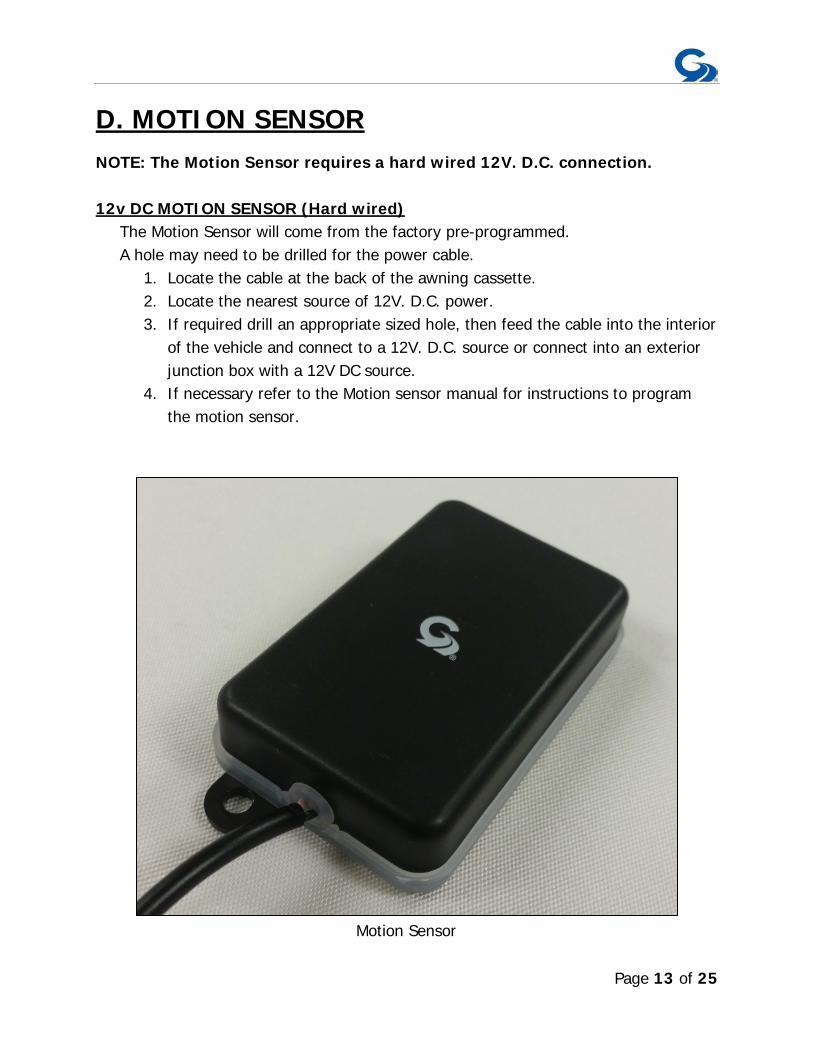
D. MOTION SENSOR NOTE: The Motion Sensor requires a hard wired 12V. D.C. connection. 12v DC MOTION SENSOR (Hard wired)
The Motion Sensor will come from the factory pre-programmed. A hole may need to be drilled for the power cable.
1. Locate the cable at the back of the awning cassette. 2. Locate the nearest source of 12V. D.C. power. 3. If required drill an appropriate sized hole, then feed the cable into the interior
of the vehicle and connect to a 12V. D.C. source or connect into an exterior junction box with a 12V DC source.
4. If necessary refer to the Motion sensor manual for instructions to program the motion sensor.
Motion Sensor
Page 14 of 25
TESTING AND ADJUSTMENTS
OVERVIEW A. Adjusting Motor-limit switches B. Adjusting Pitch C. Testing the Anemometer D. Adjusting Lead Rail
A. ADJUSTING MOTOR LIMIT SWITCHES TOOLS REQUIRED Black plastic key provided with awning, or 4mm (5/32”) Allen wrench. NOTE: The motor limit switches have been adjusted to the correct positions at the factory prior to shipment. When fully retracted the awning motor is set to stop the exact moment the awning box closes. When fully extended the fabric should be taut and the arms should be slightly bent, exposing a gap of about ¼” at the elbows. Always check the motor limits after installation to ensure that the awning opens and closes correctly. Awning fabric can stretch over time, this will require an adjustment of the OUT limit switch. IMPORTANT: EXTREME CARE SHOULD BE TAKEN TO ENSURE THAT THE MOTOR LIMIT TURNS OFF AT THE EXACT MOMENT THE AWNING BOX CLOSES. FAILURE TO DO SO WILL CAUSE THE MOTOR TO RUN WHEN THE AWNING IS CLOSED. THIS WILL SIGNIFICANTLY REDUCE THE LIFE OF THE MOTOR.
1. The AC motors used in Girard Systems awnings are reversible. Any reference made to the motor limit switches in these instructions is based on the right-hand placement of the motor. For left hand placement, simply reverse the instructions.
2. The motor has limit settings for both OUT (extension) and IN (retraction). 3. The limit switches can be adjusted by use of the black key provided with the
awning, or you may use a 4mm (5/32”) Allen wrench.
Page 15 of 25
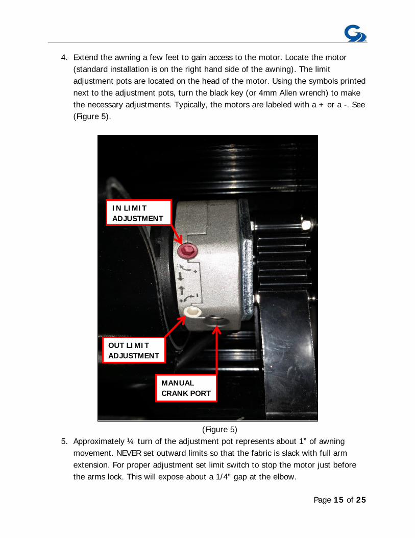
4. Extend the awning a few feet to gain access to the motor. Locate the motor (standard installation is on the right hand side of the awning). The limit adjustment pots are located on the head of the motor. Using the symbols printed next to the adjustment pots, turn the black key (or 4mm Allen wrench) to make the necessary adjustments. Typically, the motors are labeled with a + or a -. See (Figure 5).
(Figure 5) 5. Approximately ¼ turn of the adjustment pot represents about 1” of awning
movement. NEVER set outward limits so that the fabric is slack with full arm extension. For proper adjustment set limit switch to stop the motor just before the arms lock. This will expose about a 1/4” gap at the elbow.
OUT LIMIT ADJUSTMENT
IN LIMIT ADJUSTMENT
MANUAL CRANK PORT
Page 16 of 25
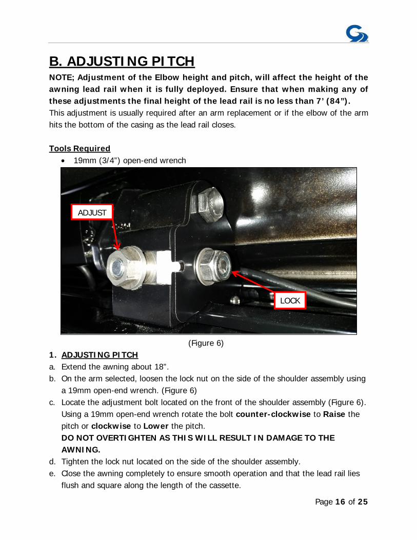
B. ADJUSTING PITCH NOTE; Adjustment of the Elbow height and pitch, will affect the height of the awning lead rail when it is fully deployed. Ensure that when making any of these adjustments the final height of the lead rail is no less than 7’ (84”). This adjustment is usually required after an arm replacement or if the elbow of the arm hits the bottom of the casing as the lead rail closes. Tools Required
• 19mm (3/4”) open-end wrench
(Figure 6) 1. ADJUSTING PITCH a. Extend the awning about 18”. b. On the arm selected, loosen the lock nut on the side of the shoulder assembly using
a 19mm open-end wrench. (Figure 6) c. Locate the adjustment bolt located on the front of the shoulder assembly (Figure 6).
Using a 19mm open-end wrench rotate the bolt counter-clockwise to Raise the pitch or clockwise to Lower the pitch. DO NOT OVERTIGHTEN AS THIS WILL RESULT IN DAMAGE TO THE AWNING.
d. Tighten the lock nut located on the side of the shoulder assembly. e. Close the awning completely to ensure smooth operation and that the lead rail lies
flush and square along the length of the cassette.
LOCK
ADJUST
Page 17 of 25
C. TESTING THE MOTION SENSOR
1. Partially extend the awning. 2. Physically activate the Motion sensor by pulling down the corner of the lead rail
about 12” and then release. This should create enough movement to activate the motion sensor.
3. At this point the awning should retract; if not, check the electrical connections to the selected power source.
NOTE: The motion sensor will only retract the awning on which it is mounted. When testing the system verify all of the awnings will close properly from the fully extended position. If the system does not operate correctly under these conditions you may:
a. Provide sufficient power from your panel. b. Try reprogramming the motion sensor.
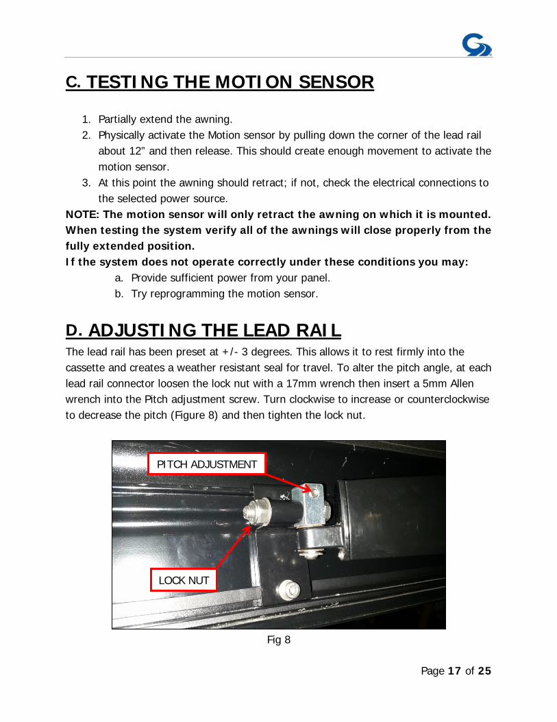
D. ADJUSTING THE LEAD RAIL The lead rail has been preset at +/- 3 degrees. This allows it to rest firmly into the cassette and creates a weather resistant seal for travel. To alter the pitch angle, at each lead rail connector loosen the lock nut with a 17mm wrench then insert a 5mm Allen wrench into the Pitch adjustment screw. Turn clockwise to increase or counterclockwise to decrease the pitch (Figure 8) and then tighten the lock nut.
Fig 8
PITCH ADJUSTMENT
LOCK NUT
Page 18 of 25
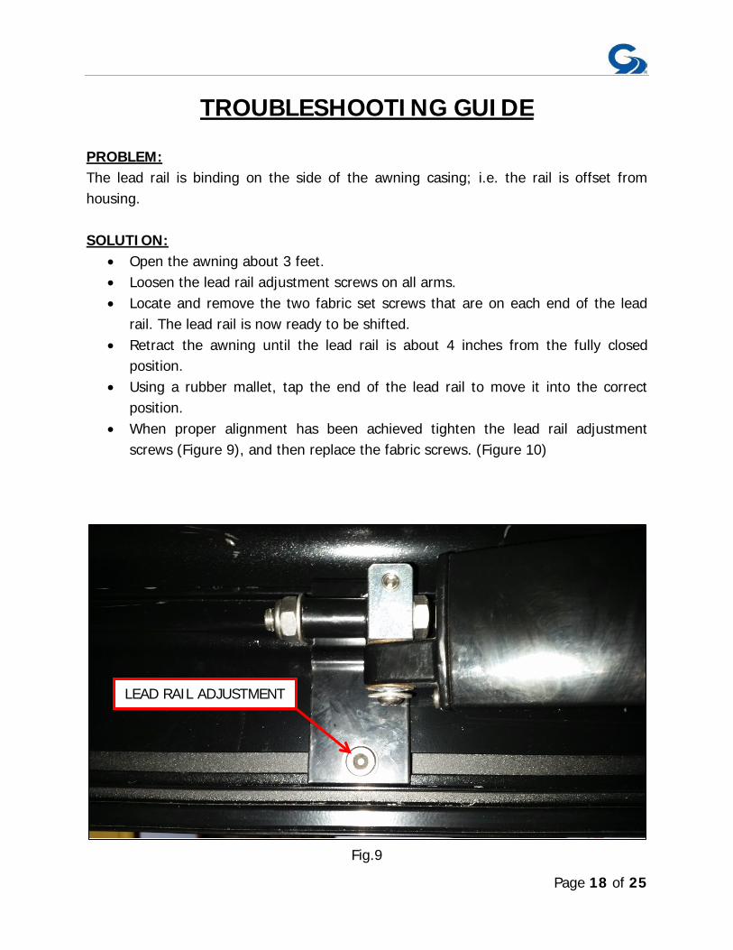
TROUBLESHOOTING GUIDE PROBLEM: The lead rail is binding on the side of the awning casing; i.e. the rail is offset from housing. SOLUTION:
• Open the awning about 3 feet. • Loosen the lead rail adjustment screws on all arms. • Locate and remove the two fabric set screws that are on each end of the lead
rail. The lead rail is now ready to be shifted. • Retract the awning until the lead rail is about 4 inches from the fully closed
position. • Using a rubber mallet, tap the end of the lead rail to move it into the correct
position. • When proper alignment has been achieved tighten the lead rail adjustment
screws (Figure 9), and then replace the fabric screws. (Figure 10)
Fig.9
LEAD RAIL ADJUSTMENT

Page 19 of 25
Fig 10 PROBLEM: The motor side of the awning closes when the awning is retracted but the opposite end does not. SOLUTION: Refer to “Adjusting the Lead Rail” on page 20. If this does not solve the issue please call the Girard Systems service line at (949)259-4000 or toll free at (800)382-8442. PROBLEM: Motor will not operate. SOLUTION:
• Check that all of the GFI switches in the vehicle are turned on. • If your vehicle has an Awnings Power Main Switch, locate that switch and make
sure it is in the ON position. • Check that the motor’s thermal protection circuit breaker has not tripped. The
110V AC motor supplied in your VISION Awning is designed for intermittent use and may cut out temporarily if it has overheated. When this occurs you must
FABRIC SCREW
Page 20 of 25
allow the motor to cool so that the internal circuit breaker can reset. This may take up to an hour depending on the outside temperature. You may use a manual crank during this period.
• If this does not solve the issue please call the Girard Systems service line at (949)259-4000 or toll free at (800)382-8442.
PROBLEM: The motor will operate for 10-12” and then stop. SOLUTION: The motor may not be receiving enough power to operate correctly.
• Check to ensure that you have a minimum of 10 amps, if not switch on your generator or connect to shore power.
• If this does not solve the issue please call the Girard Systems service line at (949)259-4000 or toll free at (800)382-8442.
PROBLEM: The fabric is loose when the awning is fully extended; i.e. the roller keeps turning after the awning arms have locked open. SOLUTION: The motors OUT limits must be reset to factory standards. Please refer to the “Adjusting the Motors Limit Switches” section on page 16-17. PROBLEM: The motor stops before the lead rail has closed completely into the awning cassette on either or both sides. There is no apparent binding of the awning components. SOLUTION: The VISION Awning is equipped with a manual override motor which has manual limit settings. The IN limit may need to be adjusted to allow the box to be closed tighter. Refer to the “Adjusting the Motors Limit Switches” section of this manual. PROBLEM: As the awning is closing, the elbow of one or more of the arms is hanging down preventing the case from closing. SOLUTION: Please refer to the “Adjusting pitch” section of this manual.
Page 21 of 25
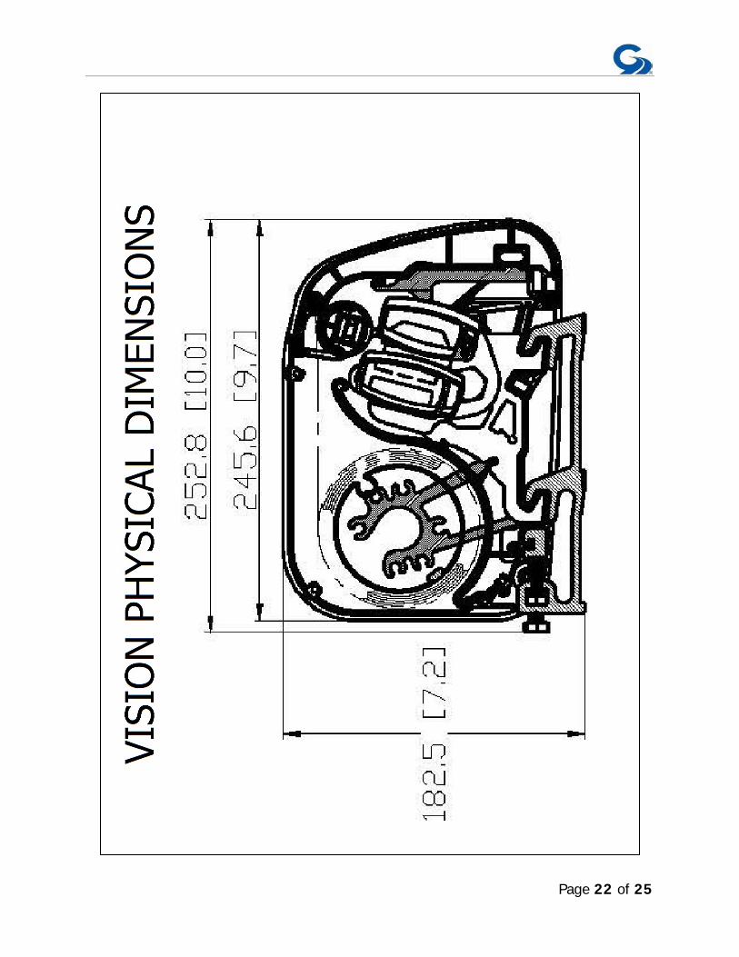
Page 22 of 25
Page 23 of 25
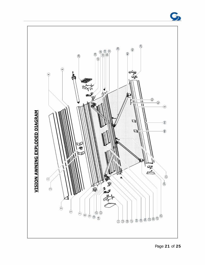
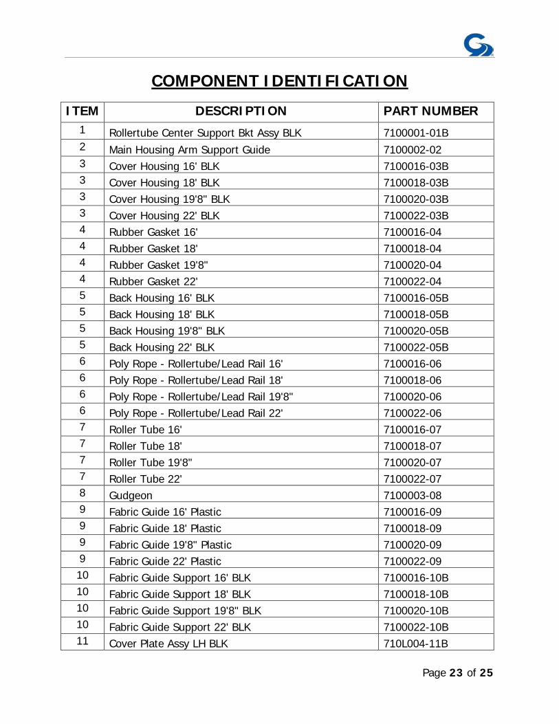
COMPONENT IDENTIFICATION ITEM DESCRIPTION PART NUMBER
1 Rollertube Center Support Bkt Assy BLK 7100001-01B 2 Main Housing Arm Support Guide 7100002-02 3 Cover Housing 16' BLK 7100016-03B 3 Cover Housing 18' BLK 7100018-03B 3 Cover Housing 19'8" BLK 7100020-03B 3 Cover Housing 22' BLK 7100022-03B 4 Rubber Gasket 16' 7100016-04 4 Rubber Gasket 18' 7100018-04 4 Rubber Gasket 19'8" 7100020-04 4 Rubber Gasket 22' 7100022-04 5 Back Housing 16' BLK 7100016-05B 5 Back Housing 18' BLK 7100018-05B 5 Back Housing 19'8" BLK 7100020-05B 5 Back Housing 22' BLK 7100022-05B 6 Poly Rope - Rollertube/Lead Rail 16' 7100016-06 6 Poly Rope - Rollertube/Lead Rail 18' 7100018-06 6 Poly Rope - Rollertube/Lead Rail 19'8" 7100020-06 6 Poly Rope - Rollertube/Lead Rail 22' 7100022-06 7 Roller Tube 16' 7100016-07 7 Roller Tube 18' 7100018-07 7 Roller Tube 19'8" 7100020-07 7 Roller Tube 22' 7100022-07 8 Gudgeon 7100003-08 9 Fabric Guide 16' Plastic 7100016-09 9 Fabric Guide 18' Plastic 7100018-09 9 Fabric Guide 19'8" Plastic 7100020-09 9 Fabric Guide 22' Plastic 7100022-09 10 Fabric Guide Support 16' BLK 7100016-10B 10 Fabric Guide Support 18' BLK 7100018-10B 10 Fabric Guide Support 19'8" BLK 7100020-10B 10 Fabric Guide Support 22' BLK 7100022-10B 11 Cover Plate Assy LH BLK 710L004-11B
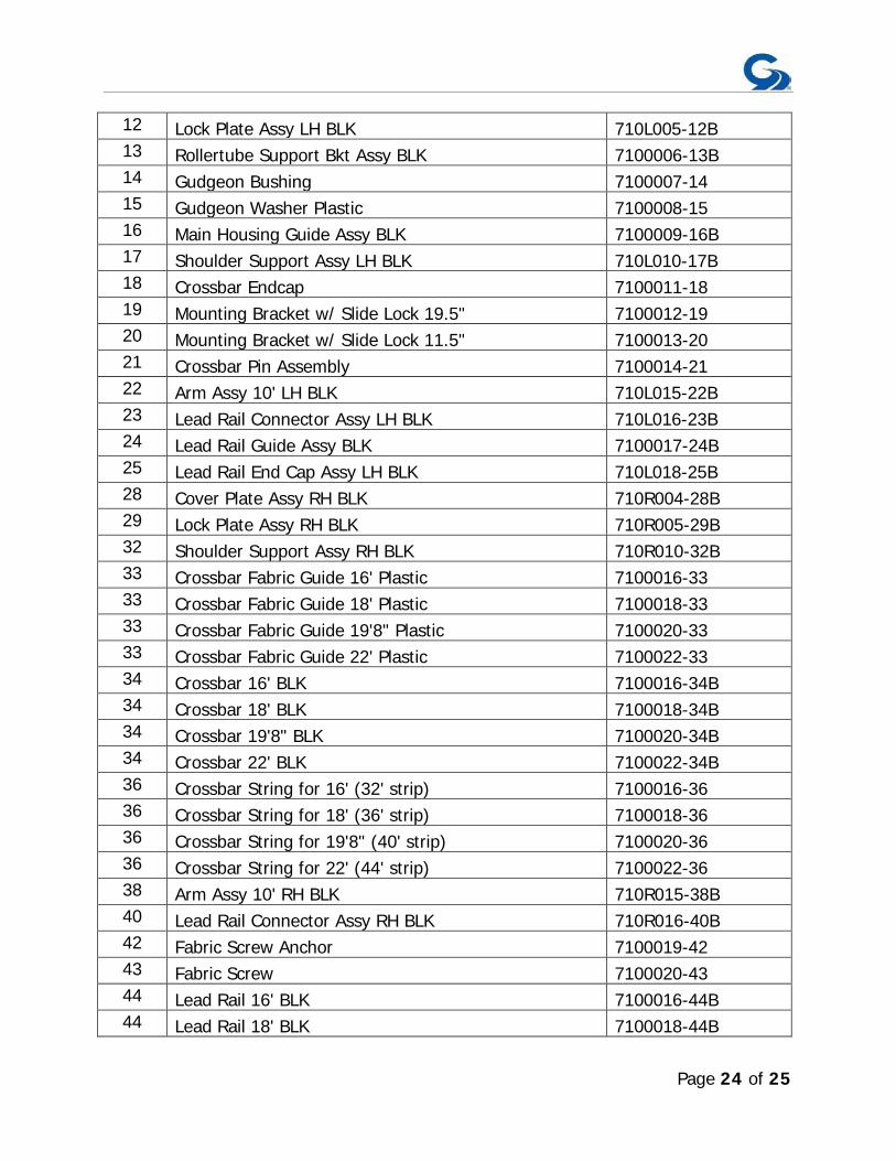
Page 24 of 25
12 Lock Plate Assy LH BLK 710L005-12B 13 Rollertube Support Bkt Assy BLK 7100006-13B 14 Gudgeon Bushing 7100007-14 15 Gudgeon Washer Plastic 7100008-15 16 Main Housing Guide Assy BLK 7100009-16B 17 Shoulder Support Assy LH BLK 710L010-17B 18 Crossbar Endcap 7100011-18 19 Mounting Bracket w/ Slide Lock 19.5" 7100012-19 20 Mounting Bracket w/ Slide Lock 11.5" 7100013-20 21 Crossbar Pin Assembly 7100014-21 22 Arm Assy 10' LH BLK 710L015-22B 23 Lead Rail Connector Assy LH BLK 710L016-23B 24 Lead Rail Guide Assy BLK 7100017-24B 25 Lead Rail End Cap Assy LH BLK 710L018-25B 28 Cover Plate Assy RH BLK 710R004-28B 29 Lock Plate Assy RH BLK 710R005-29B 32 Shoulder Support Assy RH BLK 710R010-32B 33 Crossbar Fabric Guide 16' Plastic 7100016-33 33 Crossbar Fabric Guide 18' Plastic 7100018-33 33 Crossbar Fabric Guide 19'8" Plastic 7100020-33 33 Crossbar Fabric Guide 22' Plastic 7100022-33 34 Crossbar 16' BLK 7100016-34B 34 Crossbar 18' BLK 7100018-34B 34 Crossbar 19'8" BLK 7100020-34B 34 Crossbar 22' BLK 7100022-34B 36 Crossbar String for 16' (32' strip) 7100016-36 36 Crossbar String for 18' (36' strip) 7100018-36 36 Crossbar String for 19'8" (40' strip) 7100020-36 36 Crossbar String for 22' (44' strip) 7100022-36 38 Arm Assy 10' RH BLK 710R015-38B 40 Lead Rail Connector Assy RH BLK 710R016-40B 42 Fabric Screw Anchor 7100019-42 43 Fabric Screw 7100020-43 44 Lead Rail 16' BLK 7100016-44B 44 Lead Rail 18' BLK 7100018-44B

Page 25 of 25
44 Lead Rail 19'8" BLK 7100020-44B 44 Lead Rail 22' BLK 7100022-44B 45 Lead Rail End Cap Assy RH BLK 710R018-45B 49 Lead Rail Arm Support 7100021-49
Motor Assemblies Motor Assy 45-50 w/MO 97GA45M-50 Fabric Assemblies Fabric Assy 14’ x 10’ Sunbrella 7101410-00 Fabric Assy 16’ x 10’ Sunbrella 7101610-00 Fabric Assy 18’ x 10’ Sunbrella 7101810-00 Fabric Assy 20’ x 10’ Sunbrella 7102010-00 Fabric Assy 22’ x 10’ Sunbrella 7102210-00 NOTE: WHEN QUOTING/WRITING PART NUMBERS ADD A “B” OR “W” ON THE END FOR COLOR WHERE REQUIRED.


![[Rene Girard] the Girard Reader](https://img.pdfslide.us/doc/110x75/546062a2b1af9f0e598b53cd/rene-girard-the-girard-reader.jpg)