Embed Size (px)
Citation preview

NC MachiningThe modular CAD/CAM/CAE system for tool & die makers
The modular CAD/CAM/CAE system for tool & die makers
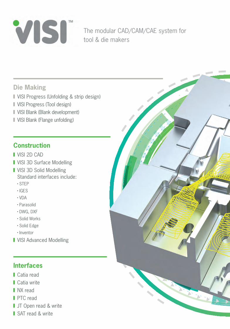
Die Making VISI Progress (Unfolding & strip design) VISI Progress (Tool design) VISI Blank (Blank development) VISI Blank (Flange unfolding)
Construction VISI 2D CAD VISI 3D Surface Modelling VISI 3D Solid Modelling
Standard interfaces include: STEP
IGES
VDA
Parasolid
DWG, DXF
Solid Works
Solid Edge
Inventor
VISI Advanced Modelling
Interfaces Catia read Catia write NX read PTC read JT Open read & write SAT read & write

Vero have been providing world class CAD/CAM solutions since 1988. VISI Machining offers all you need to increase productivity, maximise cutting capacity and reduce delivery times. VISI creates intelligent toolpaths on the most complex 3D parts.
Dedicated high speed milling techniques and built-in smoothing algorithms create highly efficient NC code, reducing cycle times on your machine, and continuously producing high quality components.
Mould Making VISI Flow VISI Analysis VISI Electrode VISI Mould
Additional Modules VISI PDM VISI Viewer
NC ProgrammingMilling & Drilling: VISI Machining 2.5-Axis VISI Machining 3-Axis VISI Machining 5-Axis VISI Compass Technology
Erosion: VISI PEPS-Wire (Wire EDM) VISI EDM (Sink Erosion)
Hole construction with Feature Manager & automated CAM processing
CAD for CAM functionality such as surface extension and dynamic run-off face construction
CAD for CAM functionality such as fillet radii analysis, feature removal, and complex hole capping
VISI AnalysisThe geometry analysis functionality and CAD for CAM tools within VISI are especially useful for effective NC programming. Important functions include:
Model comparison for design changes
Model curvature & min/ max radii analysis
Hole capping
Model thickness
Draft analysis
Surface extension / run off face construction
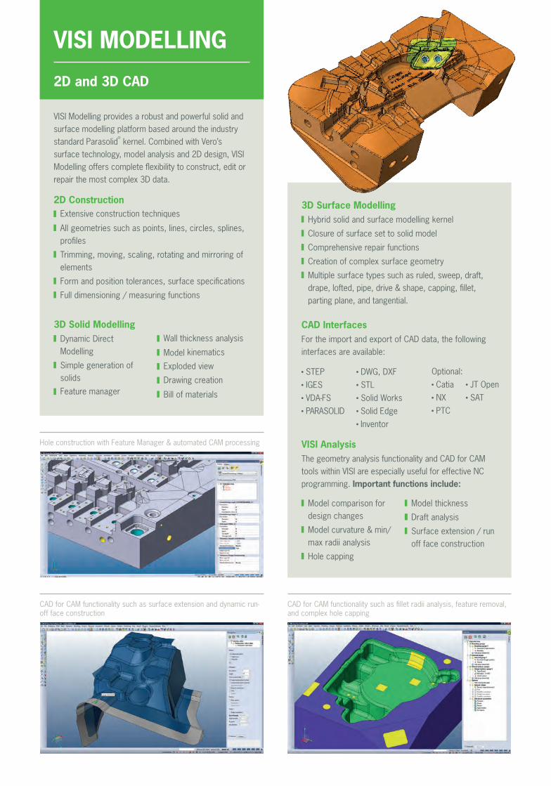
VISI MODELLING
2D and 3D CAD
VISI Modelling provides a robust and powerful solid and surface modelling platform based around the industry standard Parasolid
®
kernel. Combined with Vero’s surface technology, model analysis and 2D design, VISI Modelling offers complete flexibility to construct, edit or repair the most complex 3D data.
2D Construction Extensive construction techniques
All geometries such as points, lines, circles, splines, profiles
Trimming, moving, scaling, rotating and mirroring of elements
Form and position tolerances, surface specifications
Full dimensioning / measuring functions
3D Solid Modelling Dynamic Direct Modelling
Simple generation of solids
Feature manager
Wall thickness analysis
Model kinematics
Exploded view
Drawing creation
Bill of materials
3D Surface Modelling Hybrid solid and surface modelling kernel
Closure of surface set to solid model
Comprehensive repair functions
Creation of complex surface geometry
Multiple surface types such as ruled, sweep, draft, drape, lofted, pipe, drive & shape, capping, fillet, parting plane, and tangential.
CAD InterfacesFor the import and export of CAD data, the following interfaces are available:
STEP IGES VDA-FS PARASOLID
DWG, DXF STL Solid Works Solid Edge Inventor
Optional: Catia NX PTC
JT Open SAT

Generating the feature based toolpaths, manually or automatically with Compass Technology
Auto-recognition of drilling and pocket features in any direction, for automatic plate machining
VISI MACHINING
2.5-Axis & Feature Recognition
VISI Machining provides a practical, intuitive and simple solution for 2D programming including positional indexing. Geometry based feature recognition can select both wireframe and solid features, automatically creating reliable milling and drill cycle toolpaths.
General Features Tool, extensions and tool holder libraries
Obstacle Management
Full CNC kinematic simulation with material removal
Multi-sided machining with automatic reversal of the cutting direction
NC Report as HTML or XLS file
Feature RecognitionThe feature recognition engine evaluates the model topology and automatically detects manufacturing features with the correct drilling cycles and milling routines applied. The following feature types are recognised:
Drilling: centre drilling, tapping, reaming, boring, helical milling, thread milling and mill drill cycles
Pockets: open, rectangular, circular, irregular and rounded
Bosses: rectangular, circular, irregular and rounded
Complex Features: multi-step pockets with taper and fillet radii
Milling Milling with radius compensation
2.5D milling for complex features - extrusion, revolution or sweep
Pocketing with multi-level nested pockets
Automatic residual stock detection
Spiral or zigzag face milling
Milling by successive passes starting away from the material, gradually moving inwards
Drilling Recognition of hole and pocket features from all directions for automatic multi-face processing
User-defined complex cycles
Deep-hole drilling with feed-rate reduction for hole intersections
Support for CNC canned cycles
VISI Compass TechnologyCompass Technology is an engine that uses rules based manufacturing methods to produce intelligent CAM cycles for model features. Milling data such as cutting method, tool diameter, step over / step down; and drilling parameters such as pecking method, or the need to use counterbore or pocketing cycles for larger hole diameters can all be driven by the feature topology. Simple adaptation of the compass rules to customer-specific manufacturing methods can result in significant time savings and error reduction. Deployment of proven company standards will guarantee manufacturing consistency across any job, and any operator.
CAM data read directly from VISI Mould and VISI Progress component libraries
Automatic generation of machining programs for drilling cycles, profiling and pocketing operations
Diameters, depths and drilling parameters read directly from the model eliminate the possibility of MDI errors
Optimisation of the toolpath movement ensures the shortest distance for tool travel and reduces cycle times offering maximum productivity

VISI MACHINING
General Features Tool, extensions and tool holder libraries
Full CNC kinematic simulation with material removal
Tool path limit control using angle deviation, coordinates, profiles and check-surfaces
Dynamic incremental stock updates
Complete collision check for tool and tool holder
High speed optimised toolpath movements
Fast toolpath calculation times with multi-threading processor support
Customisable post processors
Toolpath templates for part families
Smooth point distribution
3D Pro Strategies Adaptive, trochoidal-shaped rough machining
Deep cavity roughing strategies which support multiple tool lengths / tool extensions
Rib machining - Combined roughing and finishing on the same Z plane for thin ribbed geometry such as electrodes
Combined finishing strategies for steep and shallow areas
3D constant stepover finishing
Residual material finishing - Calculation based on a residual stock model or reference tool diameter
Spiral / Radial finishing
3D curve machining
ISO-Machining for single or multi-surface selections. Extremely useful for fillet radii or picking out small areas without having to machine the entire component
Pencil milling
Flat surface machining of planar surfaces
3 + 2-Axis Machining
VISI Machining 3D is the module for machining complex 3D solids, surfaces, and STL models. The operator can choose from a variety of features and machining strategies which include dedicated high speed milling techniques and built in smoothing algorithms to create highly efficient NC code.
Finishing cycle for steep and shallow areas
3D rest machining of fine details such as small fillet radii
3D constant stepover for high quality surface finish
3D Base Strategies Multiple roughing techniques
Rest material roughing
Parallel cuts (copy milling)
Constant Z finishing
Helical finishing
Rest material finishing (calculation based on a reference tool)
VISI MACHINING VISI MACHINING
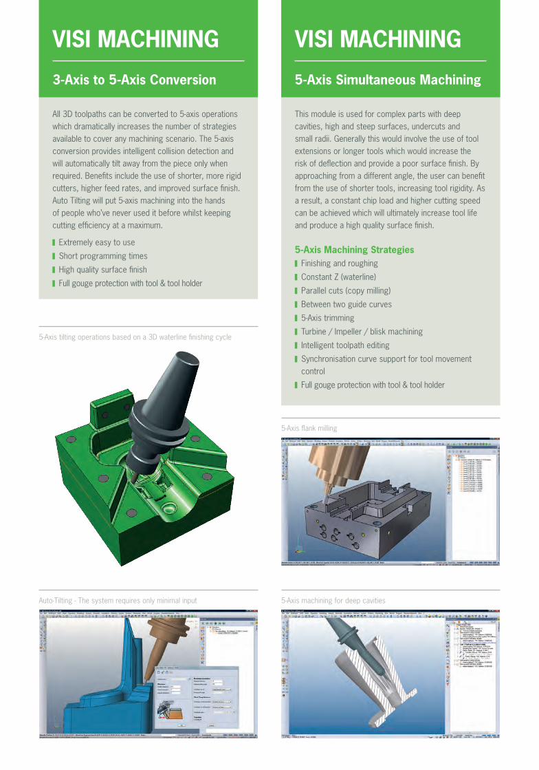
All 3D toolpaths can be converted to 5-axis operations which dramatically increases the number of strategies available to cover any machining scenario. The 5-axis conversion provides intelligent collision detection and will automatically tilt away from the piece only when required. Benefits include the use of shorter, more rigid cutters, higher feed rates, and improved surface finish. Auto Tilting will put 5-axis machining into the hands of people who’ve never used it before whilst keeping cutting efficiency at a maximum.
Extremely easy to use
Short programming times
High quality surface finish
Full gouge protection with tool & tool holder
This module is used for complex parts with deep cavities, high and steep surfaces, undercuts and small radii. Generally this would involve the use of tool extensions or longer tools which would increase the risk of deflection and provide a poor surface finish. By approaching from a different angle, the user can benefit from the use of shorter tools, increasing tool rigidity. As a result, a constant chip load and higher cutting speed can be achieved which will ultimately increase tool life and produce a high quality surface finish.
3-Axis to 5-Axis Conversion 5-Axis Simultaneous Machining
5-Axis machining for deep cavities
5-Axis flank milling
5-Axis tilting operations based on a 3D waterline finishing cycle
Auto-Tilting - The system requires only minimal input
5-Axis Machining Strategies Finishing and roughing
Constant Z (waterline)
Parallel cuts (copy milling)
Between two guide curves
5-Axis trimming
Turbine / Impeller / blisk machining
Intelligent toolpath editing
Synchronisation curve support for tool movement control
Full gouge protection with tool & tool holder
VERO SOFTWARE We speak your languageVero Software is a world leader in CAD/CAM software with a proven track record of reliable product delivery. Vero develops and distributes software for aiding the design and manufacturing processes, providing solutions for the tooling, production engineering, sheet metal, metal fabrication, stone and woodworking industries. Despite the diversity of application, these solutions have one thing in common: they all address the rising challenges of achieving manufacturing efficiencies and bring huge value to the operations where they are deployed.
The company has direct offices in the UK, Germany, Italy, France, Japan, USA, Netherlands, China, Korea, Spain and India supplying products to more than 45 countries through its wholly owned subsidiaries and global reseller network.
Part of Hexagon
Vero Software is part of Hexagon, a leading global provider of design, measurement and visualisation technologies that enable customers to design, measure and position objects, and process and present data.
Vero SoftwareHadley House, Bayshill Road, Cheltenham,Gloucestershire, GL50 3AW, UKTel: +44 (0) 1189 226699 Email: [email protected] www.visicadcam.com
For more information, please do not hesitate to get in touch
VISISoftware for improved efficiency VISI is acknowledged as the leading CAD/CAM software solution for the Mould & Die industries.
VISI offers a unique combination of fully integrated wireframe, surface and solid modelling technology, comprehensive 2D, 3D and 5-axis machining strategies with dedicated high speed routines.
Industry specific applications for plastic injection tool design including material flow analysis and progressive die design with step-by-step unfolding provide the toolmaker with unsurpassed levels of productivity.
With its comprehensive range of CAD interfaces, VISI eliminates the links between varying software suppliers and the solid-to-surface or CAD-to-CAM geometry conversions required by traditional systems.
Industry focussed technology Efficient and practical solutions Single environment for design & manufacture
We are very happy with VISI, as the software works in the same way as a toolmaker thinks. That makes VISI easy to learn and quick to integrate.“
Manfred Deifel, head of toolmaking at Rafi GmbH & Co. KG