Embed Size (px)
Citation preview

Viscous cavitiesAnne Le Goff, David Quéré, and Christophe Clanet Citation: Physics of Fluids 25, 043101 (2013); doi: 10.1063/1.4797499 View online: http://dx.doi.org/10.1063/1.4797499 View Table of Contents: http://scitation.aip.org/content/aip/journal/pof2/25/4?ver=pdfcov Published by the AIP Publishing Articles you may be interested in Fragmentation of brittle plates by localized impact Appl. Phys. Lett. 105, 124102 (2014); 10.1063/1.4896773 Locating the source of projectile fluid droplets Am. J. Phys. 79, 838 (2011); 10.1119/1.3591319 Cannon’s Recoil Against a Tree: How the Range Increases Phys. Teach. 40, 210 (2002); 10.1119/1.1474141 The use of radar-gun technology in the physics classroom/laboratory Phys. Teach. 40, 94 (2002); 10.1119/1.1457313 The physics of golf: The convex face of a driver Am. J. Phys. 69, 1073 (2001); 10.1119/1.1380380
This article is copyrighted as indicated in the article. Reuse of AIP content is subject to the terms at: http://scitation.aip.org/termsconditions. Downloaded to IP:
129.104.29.1 On: Thu, 03 Dec 2015 14:50:06
PHYSICS OF FLUIDS 25, 043101 (2013)
Viscous cavitiesAnne Le Goff,1,2 David Quere,1,3 and Christophe Clanet1,3
1PMMH, UMR 7636 du CNRS, ESPCI, 10 rue Vauquelin, 75005 Paris, France2MMN, Gulliver, UMR 7083 du CNRS, ESPCI, 10 rue Vauquelin, 75005 Paris, France3LadHyX, UMR 7646 du CNRS, Ecole Polytechnique, 91128 Palaiseau, France
(Received 3 January 2013; accepted 8 March 2013; published online 4 April 2013)
We study experimentally the impact of solid spheres in a viscous liquid at moderateReynolds numbers (Re ∼ 5–100). We first determine the drag force by following theslowdown dynamics of projectiles. We then focus on the shape of the free surface:such impacts generate cavities, whose original shape is described and modeled.C© 2013 American Institute of Physics. [http://dx.doi.org/10.1063/1.4797499]
I. INTRODUCTION
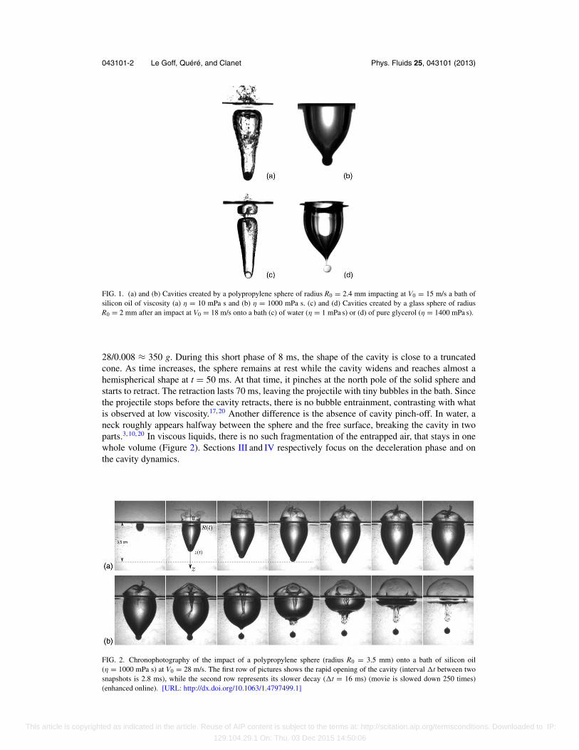
Since the pioneering work of Worthington and Cole,1 impact of solid projectiles in liquids havekept drawing the attention of researchers,2, 3 from purely theoretical fluid mechanics4 to appliedaeronautics.5 The corresponding experimental studies mainly involve disks6, 7 and spheres8, 9 im-pacting water, and they all report the formation of elongated cavities (Figures 1(a) and 1(b)) thatpinch off before the projectile stops.10, 11 These studies were extended to more complex fluids, andelongated cavities are also observed as solid spheres impact loose sand,12–15 foam,16 or viscoelasticmicellar solutions.17, 18 It is tempting to simplify the complex rheology of the fluids by consideringviscous Newtonian liquids, which we do in this paper. Fast impacts in such liquids are found to bequite different from commonly observed, as seen in Figure 1 where a comparison is made betweenthe impact cavities generated in a non-viscous and in a viscous liquid, of surface tension either low(a and b) or high (c and d). Compared to what they are in liquids 100–1000 times less viscous,cavities are found to be much wider, with an aspect ratio comparable to unity. As these centimeter-size cavities form, the projectiles stop, which stresses the natural efficiency of viscous liquids toabsorb kinetic energy. We describe in the paper the main questions raised by these observations:after presenting the experiments, we successively discuss the arrest distance of the projectile, andthe isotropic nature of the cavity in these viscous impacts.
II. EXPERIMENTAL OBSERVATIONS
We mainly use polypropylene spheres of density ρs = 920 kg/m3 comparable to that of theliquid. However, we also consider stainless steel (ρs = 7700 kg/m3), glass (ρs = 2600 kg/m3), andpolyacetal (ρs = 1410 kg/m3) in order to check the effect of the solid density. The radius R0 of theprojectile ranges from 2 mm to 5 mm. A slingshot is used to reach impact velocities from V0 = 10 m/sup to V0 = 60 m/s. The liquid in the bath is a silicon oil Rhodorsil 47V1000 of dynamic viscosityη = 1 Pa s, density ρ = 980 kg/m3, and surface tension γ = 0.02 N/m (ensuring the complete wettingof the spheres). A typical shear rate V0/R0 at impact is 104 s−1, and then quickly decreases, so thatthe dynamic viscosity is weakly affected (less than 10% decrease). At such shear rates, glycerol[Figure 1(d)] also behaves as a Newtonian fluid.19
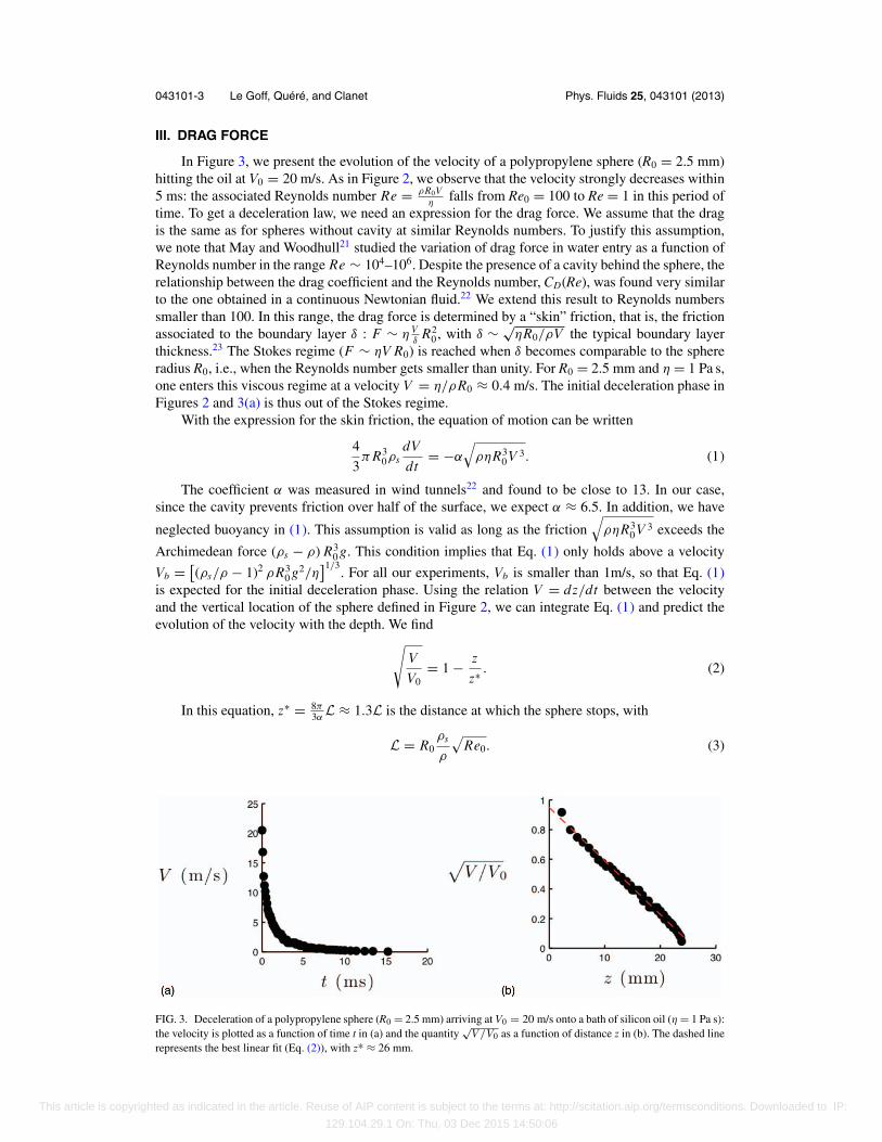
The liquids are transparent and the motion of the projectiles is recorded using a high-speedcamera (Phantom V7, 1000–10 000 frames/s). The motion is filmed from the side, using backlightingto enhance contrast, which gives access to the projectile deceleration and to the cavity formation andcollapse. A typical sequence is presented in Figure 2, which shows the dynamics of a viscous cavity,obtained after a polypropylene sphere (R0 = 3.5 mm) impacted the bath at V0 = 28 m/s. The sphereis almost stopped within the first three frames. The corresponding deceleration can be evaluated to
1070-6631/2013/25(4)/043101/7/$30.00 C©2013 American Institute of Physics25, 043101-1
This article is copyrighted as indicated in the article. Reuse of AIP content is subject to the terms at: http://scitation.aip.org/termsconditions. Downloaded to IP:
129.104.29.1 On: Thu, 03 Dec 2015 14:50:06
043101-2 Le Goff, Quere, and Clanet Phys. Fluids 25, 043101 (2013)
FIG. 1. (a) and (b) Cavities created by a polypropylene sphere of radius R0 = 2.4 mm impacting at V0 = 15 m/s a bath ofsilicon oil of viscosity (a) η = 10 mPa s and (b) η = 1000 mPa s. (c) and (d) Cavities created by a glass sphere of radiusR0 = 2 mm after an impact at V0 = 18 m/s onto a bath (c) of water (η = 1 mPa s) or (d) of pure glycerol (η = 1400 mPa s).
28/0.008 ≈ 350 g. During this short phase of 8 ms, the shape of the cavity is close to a truncatedcone. As time increases, the sphere remains at rest while the cavity widens and reaches almost ahemispherical shape at t = 50 ms. At that time, it pinches at the north pole of the solid sphere andstarts to retract. The retraction lasts 70 ms, leaving the projectile with tiny bubbles in the bath. Sincethe projectile stops before the cavity retracts, there is no bubble entrainment, contrasting with whatis observed at low viscosity.17, 20 Another difference is the absence of cavity pinch-off. In water, aneck roughly appears halfway between the sphere and the free surface, breaking the cavity in twoparts.3, 10, 20 In viscous liquids, there is no such fragmentation of the entrapped air, that stays in onewhole volume (Figure 2). Sections III and IV respectively focus on the deceleration phase and onthe cavity dynamics.
FIG. 2. Chronophotography of the impact of a polypropylene sphere (radius R0 = 3.5 mm) onto a bath of silicon oil(η = 1000 mPa s) at V0 = 28 m/s. The first row of pictures shows the rapid opening of the cavity (interval �t between twosnapshots is 2.8 ms), while the second row represents its slower decay (�t = 16 ms) (movie is slowed down 250 times)(enhanced online). [URL: http://dx.doi.org/10.1063/1.4797499.1]
This article is copyrighted as indicated in the article. Reuse of AIP content is subject to the terms at: http://scitation.aip.org/termsconditions. Downloaded to IP:
129.104.29.1 On: Thu, 03 Dec 2015 14:50:06
043101-3 Le Goff, Quere, and Clanet Phys. Fluids 25, 043101 (2013)
III. DRAG FORCE
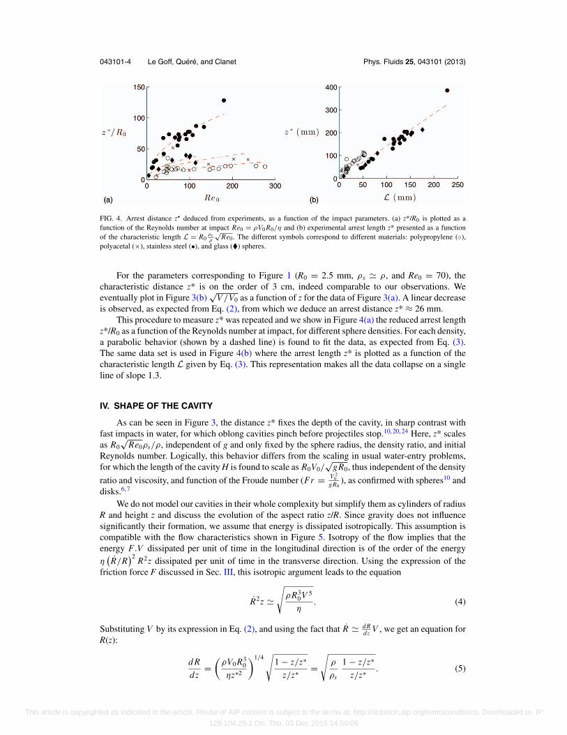
In Figure 3, we present the evolution of the velocity of a polypropylene sphere (R0 = 2.5 mm)hitting the oil at V0 = 20 m/s. As in Figure 2, we observe that the velocity strongly decreases within5 ms: the associated Reynolds number Re = ρR0V
ηfalls from Re0 = 100 to Re = 1 in this period of
time. To get a deceleration law, we need an expression for the drag force. We assume that the dragis the same as for spheres without cavity at similar Reynolds numbers. To justify this assumption,we note that May and Woodhull21 studied the variation of drag force in water entry as a function ofReynolds number in the range Re ∼ 104–106. Despite the presence of a cavity behind the sphere, therelationship between the drag coefficient and the Reynolds number, CD(Re), was found very similarto the one obtained in a continuous Newtonian fluid.22 We extend this result to Reynolds numberssmaller than 100. In this range, the drag force is determined by a “skin” friction, that is, the frictionassociated to the boundary layer δ : F ∼ η V
δR2
0, with δ ∼ √ηR0/ρV the typical boundary layer
thickness.23 The Stokes regime (F ∼ ηV R0) is reached when δ becomes comparable to the sphereradius R0, i.e., when the Reynolds number gets smaller than unity. For R0 = 2.5 mm and η = 1 Pa s,one enters this viscous regime at a velocity V = η/ρR0 ≈ 0.4 m/s. The initial deceleration phase inFigures 2 and 3(a) is thus out of the Stokes regime.
With the expression for the skin friction, the equation of motion can be written
4
3π R3
0ρsdV
dt= −α
√ρηR3
0 V 3. (1)
The coefficient α was measured in wind tunnels22 and found to be close to 13. In our case,since the cavity prevents friction over half of the surface, we expect α ≈ 6.5. In addition, we have
neglected buoyancy in (1). This assumption is valid as long as the friction√
ρηR30 V 3 exceeds the
Archimedean force (ρs − ρ) R30 g. This condition implies that Eq. (1) only holds above a velocity
Vb = [(ρs/ρ − 1)2 ρR3
0 g2/η]1/3
. For all our experiments, Vb is smaller than 1m/s, so that Eq. (1)is expected for the initial deceleration phase. Using the relation V = dz/dt between the velocityand the vertical location of the sphere defined in Figure 2, we can integrate Eq. (1) and predict theevolution of the velocity with the depth. We find√
V
V0= 1 − z
z∗ . (2)
In this equation, z∗ = 8π3αL ≈ 1.3L is the distance at which the sphere stops, with
L = R0ρs
ρ
√Re0. (3)
FIG. 3. Deceleration of a polypropylene sphere (R0 = 2.5 mm) arriving at V0 = 20 m/s onto a bath of silicon oil (η = 1 Pa s):the velocity is plotted as a function of time t in (a) and the quantity
√V/V0 as a function of distance z in (b). The dashed line
represents the best linear fit (Eq. (2)), with z* ≈ 26 mm.
This article is copyrighted as indicated in the article. Reuse of AIP content is subject to the terms at: http://scitation.aip.org/termsconditions. Downloaded to IP:
129.104.29.1 On: Thu, 03 Dec 2015 14:50:06
043101-4 Le Goff, Quere, and Clanet Phys. Fluids 25, 043101 (2013)
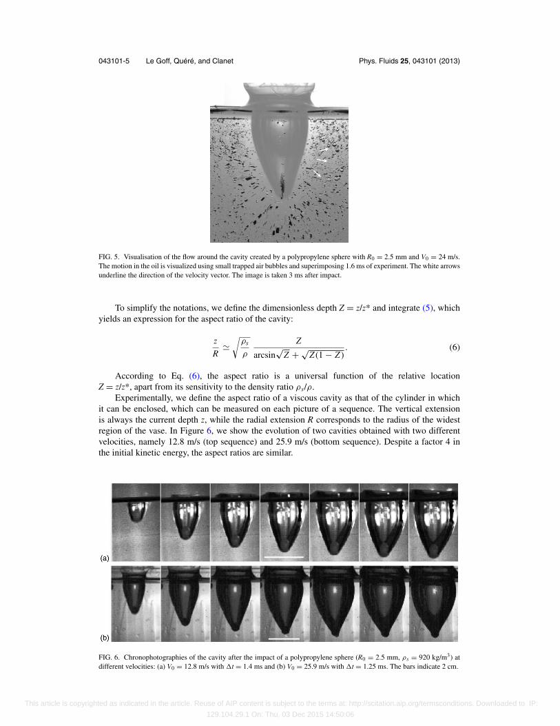
FIG. 4. Arrest distance z deduced from experiments, as a function of the impact parameters. (a) z*/R0 is plotted as afunction of the Reynolds number at impact Re0 = ρV0 R0/η and (b) experimental arrest length z* presented as a functionof the characteristic length L = R0
ρsρ
√Re0. The different symbols correspond to different materials: polypropylene (◦),
polyacetal (×), stainless steel (•), and glass (�) spheres.
For the parameters corresponding to Figure 1 (R0 = 2.5 mm, ρs � ρ, and Re0 = 70), thecharacteristic distance z* is on the order of 3 cm, indeed comparable to our observations. Weeventually plot in Figure 3(b)
√V/V0 as a function of z for the data of Figure 3(a). A linear decrease
is observed, as expected from Eq. (2), from which we deduce an arrest distance z* ≈ 26 mm.This procedure to measure z* was repeated and we show in Figure 4(a) the reduced arrest length
z*/R0 as a function of the Reynolds number at impact, for different sphere densities. For each density,a parabolic behavior (shown by a dashed line) is found to fit the data, as expected from Eq. (3).The same data set is used in Figure 4(b) where the arrest length z* is plotted as a function of thecharacteristic length L given by Eq. (3). This representation makes all the data collapse on a singleline of slope 1.3.
IV. SHAPE OF THE CAVITY
As can be seen in Figure 3, the distance z* fixes the depth of the cavity, in sharp contrast withfast impacts in water, for which oblong cavities pinch before projectiles stop.10, 20, 24 Here, z* scalesas R0
√Re0ρs/ρ, independent of g and only fixed by the sphere radius, the density ratio, and initial
Reynolds number. Logically, this behavior differs from the scaling in usual water-entry problems,for which the length of the cavity H is found to scale as R0V0/
√gR0, thus independent of the density
ratio and viscosity, and function of the Froude number (Fr = V 20
gR0), as confirmed with spheres10 and
disks.6, 7
We do not model our cavities in their whole complexity but simplify them as cylinders of radiusR and height z and discuss the evolution of the aspect ratio z/R. Since gravity does not influencesignificantly their formation, we assume that energy is dissipated isotropically. This assumption iscompatible with the flow characteristics shown in Figure 5. Isotropy of the flow implies that theenergy F.V dissipated per unit of time in the longitudinal direction is of the order of the energyη
(R/R
)2R2z dissipated per unit of time in the transverse direction. Using the expression of the
friction force F discussed in Sec. III, this isotropic argument leads to the equation
R2z �√
ρR30 V 5
η. (4)
Substituting V by its expression in Eq. (2), and using the fact that R � d Rdz V , we get an equation for
R(z):
d R
dz=
(ρV0 R3
0
ηz∗2
)1/4√
1 − z/z∗
z/z∗ =√
ρ
ρs
1 − z/z∗
z/z∗ . (5)
This article is copyrighted as indicated in the article. Reuse of AIP content is subject to the terms at: http://scitation.aip.org/termsconditions. Downloaded to IP:
129.104.29.1 On: Thu, 03 Dec 2015 14:50:06
043101-5 Le Goff, Quere, and Clanet Phys. Fluids 25, 043101 (2013)
FIG. 5. Visualisation of the flow around the cavity created by a polypropylene sphere with R0 = 2.5 mm and V0 = 24 m/s.The motion in the oil is visualized using small trapped air bubbles and superimposing 1.6 ms of experiment. The white arrowsunderline the direction of the velocity vector. The image is taken 3 ms after impact.
To simplify the notations, we define the dimensionless depth Z = z/z* and integrate (5), whichyields an expression for the aspect ratio of the cavity:
z
R�
√ρs
ρ
Z
arcsin√
Z + √Z (1 − Z )
. (6)
According to Eq. (6), the aspect ratio is a universal function of the relative locationZ = z/z*, apart from its sensitivity to the density ratio ρs/ρ.
Experimentally, we define the aspect ratio of a viscous cavity as that of the cylinder in whichit can be enclosed, which can be measured on each picture of a sequence. The vertical extensionis always the current depth z, while the radial extension R corresponds to the radius of the widestregion of the vase. In Figure 6, we show the evolution of two cavities obtained with two differentvelocities, namely 12.8 m/s (top sequence) and 25.9 m/s (bottom sequence). Despite a factor 4 inthe initial kinetic energy, the aspect ratios are similar.
FIG. 6. Chronophotographies of the cavity after the impact of a polypropylene sphere (R0 = 2.5 mm, ρs = 920 kg/m3) atdifferent velocities: (a) V0 = 12.8 m/s with �t = 1.4 ms and (b) V0 = 25.9 m/s with �t = 1.25 ms. The bars indicate 2 cm.
This article is copyrighted as indicated in the article. Reuse of AIP content is subject to the terms at: http://scitation.aip.org/termsconditions. Downloaded to IP:
129.104.29.1 On: Thu, 03 Dec 2015 14:50:06
043101-6 Le Goff, Quere, and Clanet Phys. Fluids 25, 043101 (2013)
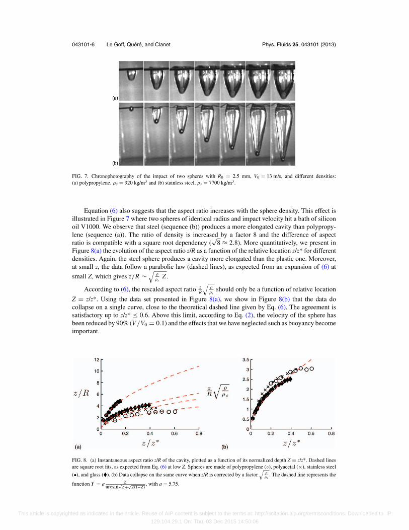
FIG. 7. Chronophotography of the impact of two spheres with R0 = 2.5 mm, V0 = 13 m/s, and different densities:(a) polypropylene, ρs = 920 kg/m3 and (b) stainless steel, ρs = 7700 kg/m3.
Equation (6) also suggests that the aspect ratio increases with the sphere density. This effect isillustrated in Figure 7 where two spheres of identical radius and impact velocity hit a bath of siliconoil V1000. We observe that steel (sequence (b)) produces a more elongated cavity than polypropy-lene (sequence (a)). The ratio of density is increased by a factor 8 and the difference of aspectratio is compatible with a square root dependency (
√8 ≈ 2.8). More quantitatively, we present in
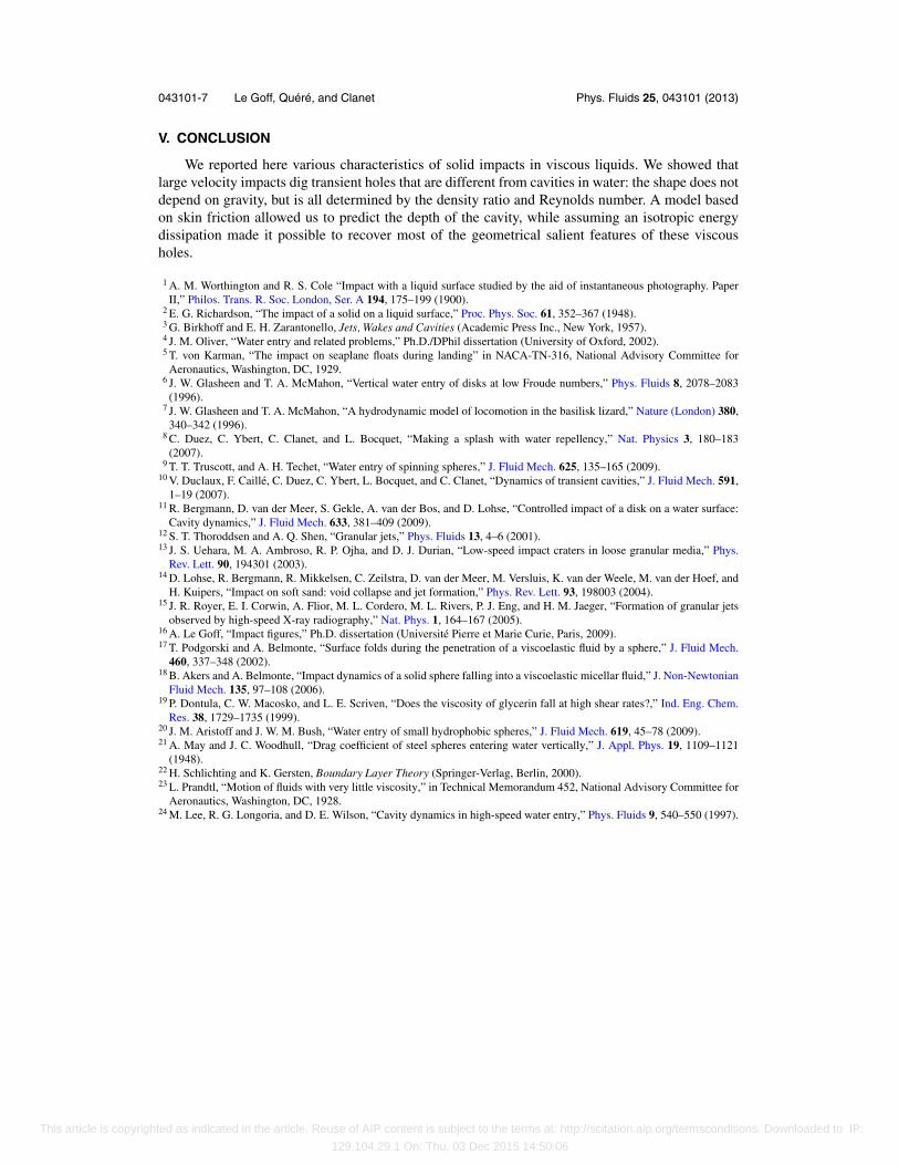
Figure 8(a) the evolution of the aspect ratio z/R as a function of the relative location z/z* for differentdensities. Again, the steel sphere produces a cavity more elongated than the plastic one. Moreover,at small z, the data follow a parabolic law (dashed lines), as expected from an expansion of (6) at
small Z, which gives z/R ∼√
ρ
ρsZ .
According to (6), the rescaled aspect ratio zR
√ρ
ρsshould only be a function of relative location
Z = z/z*. Using the data set presented in Figure 8(a), we show in Figure 8(b) that the data docollapse on a single curve, close to the theoretical dashed line given by Eq. (6). The agreement issatisfactory up to z/z* ≤ 0.6. Above this limit, according to Eq. (2), the velocity of the sphere hasbeen reduced by 90% (V/V0 = 0.1) and the effects that we have neglected such as buoyancy becomeimportant.
FIG. 8. (a) Instantaneous aspect ratio z/R of the cavity, plotted as a function of its normalized depth Z = z/z*. Dashed linesare square root fits, as expected from Eq. (6) at low Z. Spheres are made of polypropylene (◦), polyacetal (×), stainless steel
(•), and glass (�). (b) Data collapse on the same curve when z/R is corrected by a factor√
ρρs
. The dashed line represents the
function Y = a Zarcsin
√Z+√
Z (1−Z ), with a = 5.75.
This article is copyrighted as indicated in the article. Reuse of AIP content is subject to the terms at: http://scitation.aip.org/termsconditions. Downloaded to IP:
129.104.29.1 On: Thu, 03 Dec 2015 14:50:06
043101-7 Le Goff, Quere, and Clanet Phys. Fluids 25, 043101 (2013)
V. CONCLUSION
We reported here various characteristics of solid impacts in viscous liquids. We showed thatlarge velocity impacts dig transient holes that are different from cavities in water: the shape does notdepend on gravity, but is all determined by the density ratio and Reynolds number. A model basedon skin friction allowed us to predict the depth of the cavity, while assuming an isotropic energydissipation made it possible to recover most of the geometrical salient features of these viscousholes.
1 A. M. Worthington and R. S. Cole “Impact with a liquid surface studied by the aid of instantaneous photography. PaperII,” Philos. Trans. R. Soc. London, Ser. A 194, 175–199 (1900).
2 E. G. Richardson, “The impact of a solid on a liquid surface,” Proc. Phys. Soc. 61, 352–367 (1948).3 G. Birkhoff and E. H. Zarantonello, Jets, Wakes and Cavities (Academic Press Inc., New York, 1957).4 J. M. Oliver, “Water entry and related problems,” Ph.D./DPhil dissertation (University of Oxford, 2002).5 T. von Karman, “The impact on seaplane floats during landing” in NACA-TN-316, National Advisory Committee for
Aeronautics, Washington, DC, 1929.6 J. W. Glasheen and T. A. McMahon, “Vertical water entry of disks at low Froude numbers,” Phys. Fluids 8, 2078–2083
(1996).7 J. W. Glasheen and T. A. McMahon, “A hydrodynamic model of locomotion in the basilisk lizard,” Nature (London) 380,
340–342 (1996).8 C. Duez, C. Ybert, C. Clanet, and L. Bocquet, “Making a splash with water repellency,” Nat. Physics 3, 180–183
(2007).9 T. T. Truscott, and A. H. Techet, “Water entry of spinning spheres,” J. Fluid Mech. 625, 135–165 (2009).
10 V. Duclaux, F. Caille, C. Duez, C. Ybert, L. Bocquet, and C. Clanet, “Dynamics of transient cavities,” J. Fluid Mech. 591,1–19 (2007).
11 R. Bergmann, D. van der Meer, S. Gekle, A. van der Bos, and D. Lohse, “Controlled impact of a disk on a water surface:Cavity dynamics,” J. Fluid Mech. 633, 381–409 (2009).
12 S. T. Thoroddsen and A. Q. Shen, “Granular jets,” Phys. Fluids 13, 4–6 (2001).13 J. S. Uehara, M. A. Ambroso, R. P. Ojha, and D. J. Durian, “Low-speed impact craters in loose granular media,” Phys.
Rev. Lett. 90, 194301 (2003).14 D. Lohse, R. Bergmann, R. Mikkelsen, C. Zeilstra, D. van der Meer, M. Versluis, K. van der Weele, M. van der Hoef, and
H. Kuipers, “Impact on soft sand: void collapse and jet formation,” Phys. Rev. Lett. 93, 198003 (2004).15 J. R. Royer, E. I. Corwin, A. Flior, M. L. Cordero, M. L. Rivers, P. J. Eng, and H. M. Jaeger, “Formation of granular jets
observed by high-speed X-ray radiography,” Nat. Phys. 1, 164–167 (2005).16 A. Le Goff, “Impact figures,” Ph.D. dissertation (Universite Pierre et Marie Curie, Paris, 2009).17 T. Podgorski and A. Belmonte, “Surface folds during the penetration of a viscoelastic fluid by a sphere,” J. Fluid Mech.
460, 337–348 (2002).18 B. Akers and A. Belmonte, “Impact dynamics of a solid sphere falling into a viscoelastic micellar fluid,” J. Non-Newtonian
Fluid Mech. 135, 97–108 (2006).19 P. Dontula, C. W. Macosko, and L. E. Scriven, “Does the viscosity of glycerin fall at high shear rates?,” Ind. Eng. Chem.
Res. 38, 1729–1735 (1999).20 J. M. Aristoff and J. W. M. Bush, “Water entry of small hydrophobic spheres,” J. Fluid Mech. 619, 45–78 (2009).21 A. May and J. C. Woodhull, “Drag coefficient of steel spheres entering water vertically,” J. Appl. Phys. 19, 1109–1121
(1948).22 H. Schlichting and K. Gersten, Boundary Layer Theory (Springer-Verlag, Berlin, 2000).23 L. Prandtl, “Motion of fluids with very little viscosity,” in Technical Memorandum 452, National Advisory Committee for
Aeronautics, Washington, DC, 1928.24 M. Lee, R. G. Longoria, and D. E. Wilson, “Cavity dynamics in high-speed water entry,” Phys. Fluids 9, 540–550 (1997).
This article is copyrighted as indicated in the article. Reuse of AIP content is subject to the terms at: http://scitation.aip.org/termsconditions. Downloaded to IP:
129.104.29.1 On: Thu, 03 Dec 2015 14:50:06