Embed Size (px)
Citation preview
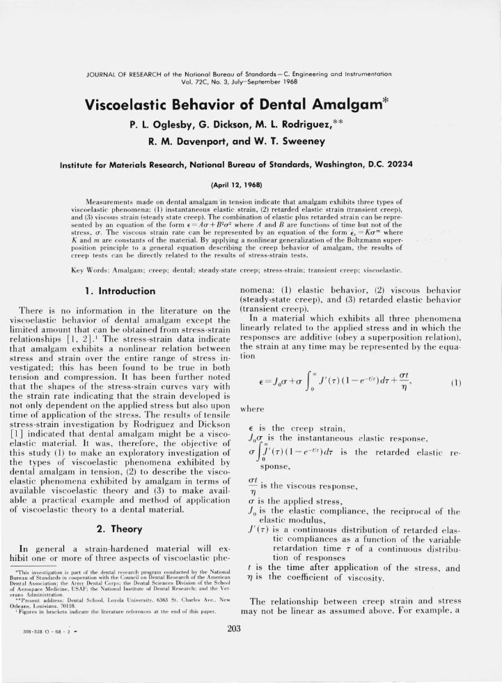
JOURNAL O F RESEARCH of the National Bureau of Stondards - C. Engineering and tnstrumentatio n Vol . 72C, No.3, July- September 1968
Viscoelastic Behavior of Dental Amalgam* P. L. Oglesby, G. Dickson, M. L. Rodriguez, **
R. M. Davenport, and W. T. Sweeney
Institute for Materials Research, National Bureau of Standards, Washington, D.C. 20234
(April 12, 1968)
Measure ments made on dent a l a malgam in tens ion indica te th at a malga m exhib its three types of vi scoelasti c phe nome na: (1) inst antaneous e las ti c s tra in , (2) re ta rded e las ti c st ra in (transie nt c reep), and (3) viscous s train (s teady state c reep). T he co mbina tion of e lasti c plus re ta rded strain can be repre· sent ed by a n eq uation of the form f = A(T + 8 '(J' where A a nd 8 a re fun c ti ons of time but not of the stress, (J . T he viscous s train ra te ca n be represented b y a n equ a tion of the form €v = K(J'" where K a nd m a re constants of the mate ri a l. By a pplying a nonlin ear genera li zation of th e Bolt zma nn s upe rposi ti on principl e to a ge neral eq ua tion descri bing the creep behav ior of a malgam, the results of c reep tests can be d irectl y re la ted to the resu lts of st ress-s train tes ts.
Key Words: Amalgam; c reep; dental ; steady-state c reep; s tress-stra in ; trans ient c reep; viscoelasti c.
1. Introduction
Th ere is no info rmation in the literature on the vi scoelas ti c be ha vi or of de ntal amalga m except the limited a mount th at ca n be obtained f rom s tress-s train relationshi ps [1 , 2] .1 Th e s tress-stra in data indicate tha t amalgam ex hibits a nonlinear rela ti on be tween s tress and stra in over the entire range of stress inves tigated; thi s has been found to be true in bo th ten sion and co mpress ion. It has bee n fu r th er noted th at th e shapes of the s tress-s train c urves vary with the strain rate indicatin g th at th e s train deve loped is n01 only depende nt on the a ppli ed s tress but also upon time of applica tion of th e stress. The res ults of tensile s tress-s train inves ti ga tion by Rodriguez a nd Di ckso n [I J indicated th at de nta l a malga m mi ght be a vi scoelas ti c materi a l. It was, the refo re, the obj ec ti ve of thi s s tudy (1) to ma ke a n exploratory investigation of the types of viscoelas ti c phe nomena exhibited by dental a malgam in tension, (2) to describe the vi scoelas ti c phenome na ex hibited by a malgam in terms of available viscoelasti c theo ry and (3) to make available a prac ti cal example and method of appli cation of vi scoe las ti c theory to a dental materia l.
2. Theory
In ge ner al a strain-h ardened materi al will exhibit one or more of three aspec ts of viscoelas ti c phe-
*This inves t igat ion is part of the denial research progra m conducted by the Nali?nal Bureau of Standards in cooperat ion wilh th e Counc il o n De ntal Researc h of the Ame ncan Denta l Associa tion; the Arm y Den ta l Corps; the Dental Scie nces Divisio n of the School of Aerospace Medic ine. USAF; the Na tional Ins titute of Denta l Research ; and the Vet· cran s Adminis tration.
** Present address: Dent a l School. Loyola Univers it y. 6363 S I. C har les Ave., Ne w O rleans, Louis iana. 70 118.
I Figu res ill brac kets indica te the li te rature references II I t il e end of th is paper.
nome n a: (1) elas ti c be havior , (2) vi scous be ha vior (stead y-s tate c reep), and (3) re tarded elas ti c be hav ior (tra nsie nt creep).
In a materi a l whi ch ex hibits all three ph e nome na linearly rela ted to th e a pplied s t ress and in whi ch the res ponses are additi ve (obey a s uperpos ition relation), th e s train at a ny time may be re prese nted by the eq uation
f ~ u t E = .lou + u .J ' (T) (1 - e- t/T )(iT +-,
o TJ
wh ere
E is the creep s train , .lou is the in s tantaneous e las ti c response,
u J l (T) (1 - e- I /T ) dT is the retarded e las ti c
sponse,
u t. h . - IS t e VISCO US res ponse, TJ u is th e a pplied stress,
(1)
re-
.J 0 is the e las ti c compliance, the reciproca l of th e elas ti c modulus,
./' (T) is a continuous di stribution of re tarded elasti c compliances as a fun ction of the va ri ab le retardation time T of a continuous di s l ri bution of res ponses
I S the time after application of th e s tress, a nd TJ is the coeffi cie nt of vi scos ity.
The relationship between creep strain a nd stress may not be linear as ass um ed a bove. For exa mple , a
308-528 0 - 68 - 2 ~ 203
material may obey the following equation:
E= .J"a- + a- (x .J ' (T) (1- e- f/r)dT Jo
(2)
where K (a--a-O)lIIt = O for all valu es of a- ~ a-u and (3 (y ) is a continuous di s tribution of re tarded
elastic co mplian ces as a fun ction of the variable re tardation time y of a continuous di stribution of res ponses in the nonlinear second degree stress res ponse of the material ,
a-o is the applied stress level at which the materi al begins to exhibit a viscou s flow , and
K and m are cons tants at any give n te mperature. Where the cree p strain is linearl y rela ted to the
applied s tress, the strain can be writte n as a product of a gene ral c ree p compli ance, which is a fun c tion of time only, and the applied s tress as give n by the fol· lowin g equ ation:
E= .J (t )a- , (3) where
E is the cree p s train de veloped , a- is th e a pplied stress, and .I (t ) is the ge neral c ree p co mpliance.
For example , in the lin ear cree p behavior as seen in equation (1), the gene ral cree p compliance .I (t ) IS of the form :
.J(t) = .J( + Ii' (T) (1- e- f/r) dT + (4) ) H TJ
In the case that cree p strain is linearly related to the applied stress, the stress-strain be havior for a material may be related to the cree p behavior by means of the linear superposition principle de veloped by Boltzmann [3] as shown below:
(5)
or
(6)
where
a- is the ap plied stress related to the experime ntal tim e e in a prescribed ex· perime ntal fun ctional re lat ion,
E (T) is the s train of a s tress-strain re la tion measured at a time T subsequent to the variable time e, and
da- (e ) . . de- de IS the Incre me nt of stress from tim e e
to time (e + de ).
For exa mple, applying the Boltzmann s uperposition principle to the example of cree p given in eq (1) gives the following relation between cr ee p behavior a nd the s train measured in a stress-strain test [4]:
E (T ) = .J ,a- + .J '(T)( l - e - - r- )d7 _a-_ de 11' IX (1'- 0) d (e) ( 0 0 de
+ 11' a-(e) de. (7) o YJ
A discussion of the application of the Boltzmann superposition principle as applied to linear viscoelasti c pheno me na is give n by Leaderman [5]. However , if a material exhibits a nonlin ear relation in its retarded s train (transient c reep) and the a ppli ed s tress as di~cu:sed earli er , the linear Boltzmann superposItion prmclple cannot be appli ed to relate s train of a stresss train tes t on the material to the creep s train . A <Te neralization of Boltzmann 's superposition principle de velo ped by Nakada [6] may be used to relate nonlinear re tarded e las ti c cree p behavior to the stressstrain behavior of the material as given :
Eu (a-) = f(T(1') '-I'(T- e)da- (e ) + o
f <T(T) f"(1')
o 0 cf> ( T - e , T - cp) da- ( e ) da- ( 1> )
10-(1') 1"(1') 1,,(T)
+ F (T - e , o H 0
T-cp , T-a)da- (e )da- (cp )da- (a ) + . . (8)
Now for example, consider the a ppli cation of the nonlinear superposition principle of Nakada as applied to the case of re tarded s train (transie nt cree p) re lated to the a pplied stress by a second degree equation as shown earli er:
(9)
where '-I' ( t ) and cf> (t ) could be r e presented by the equation shown below in accord ance with th e Voigt mode l
'-I' (t ) = f x .J' (7) (1 - e- f/r) dT , o
cf> (t ) =1'" (3 (y ) (l -e- f /Y )dy· o
If on e applies an approximation of Nakada's general formulation described by Leaderm an , McC rackin , and Nakada [7] , the equation re presenting the reo tarded e lasti c r es ponse takes the following form :
E (a- (T)) = l "(1'q,.(T - e)da-(e) /I 0
204
+ (<T(T) (CT(T) cf>(T - O)<'P( T - 4»da- (O)da-(4». In In
(10)
Conside rin g an example of a material whi ch exhibits all three ph e nom ena but in whic h the cr ee p s train is a nonlinear fun c ti on of the appli ed s tress acco rding to eq (2), then applying th e above approximation of the nonlinear s upe rposition princ iple, the s tress· strain behavi or of th e mate rial may be related to the creep behavi or by the followin g equati on:
E = a-iu + rr '¥ (T - 0) da- ( 0) Jo
+ {T rr <'P (T - 0) cf> (T - 4> ) da- ( 0) da- ( 4> ) Jo Jo
+IT K(a-(O) - a-o )/IIdO. o
(11)
However , as will be di scussed Later, it was found in the inves tigation that a diffe re nt approximation is required to describe the be havior of de ntal amalgam.
3. Materials Th e s pecim e ns we re pre pared us in g a co mmer·
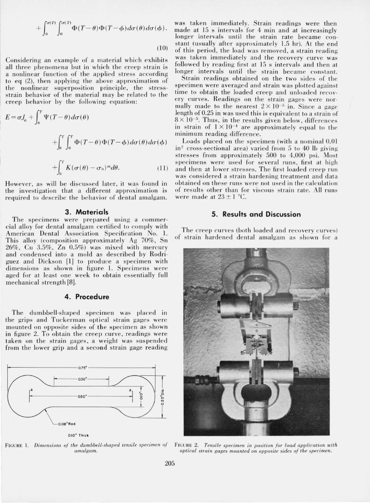
cial alloy for dental amalgam ce rtifi ed to co mply with American Dental Association Specifi cation No. 1. Thi s all oy (co mposition approximately Ag 70%, Sn 26%, Cu 3.5%, Zn 0.5%) was mixed with merc ury and conde nsed into a mold as described by Rodri· guez and Dic kson [1] to produce a specime n with dimension s as s hown in fi gure 1. Specimens were aged for at leas t one week to obtain esse nti ally full mechanical strength [8].
4. Procedure
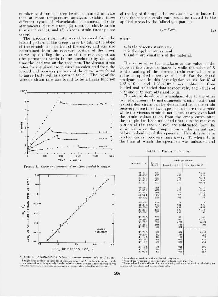
The dumbbe ll·s haped s pecime n was placed in the grips and Tuc ke rman optical strain gages were mounted on opposite sides of the specimen as shown in fi gure 2. To obtain th e c ree p curve, readings were taken on the strain gages, a weight was sus pended from the lower grip and a second· strain gage reading
II r - 0.75
'-------' 1-----Q30'-------.
IA
1-. -------0.50"--------1
o.oe" Rod.
0.10" Thick
FI GU RE I. Dimensions oj the du.mbbell·shaped tensile specimen oj amalgam.
was taken immediately. Strain readings were then made at 15 s intervals for 4 min and at increasingly longer interval s until th e str ain rate became con· stant (usually after approximately 1.5 hr). At the end of this period , th e load was re moved , a strain reading was taken imm ediately a nd the recovery curve was followed by reading fir st at 15 s intervals and then at lon ger intervals until the strain became co ns ta nt.
Strain readings obtained on the two sides of th e specimen were average d and strain was plotted against time to obtain the loaded c ree p and unloaded recov· ery c urves. Readings on the s train gages were nor· mally made to the neares t 2 X 10- 0 in. S in ce a gage length of 0.25 in was used this is equival e nt to a s tra in of 8 X 10- 5 • Thus , in the results given be lo w, diffe re nces in strain of 1 X 10- 4 are approximate ly eq ua l to the minimum reading difference.
Loads placed on the s pecim en (with a no minal 0.01 in ~ c ross·sec tional area) vari ed from 5 to 40 lb givin g stresses from approximately 500 to 4,000 psi. Most specim e ns were used for seve ral run s, fir st at hi gh and th e n at lower s tresses . The firs t loaded cree p run was cons idered a s tra in harde nin g treatm ent and dat a obtained on these run s were not used in th e calc ulation of res ults other th a n for vi scous s train rate. All run s we re made at 23 ± 1 0c.
5. Results and Discussion
Th e c ree p c urves (both loaded and recove ry c u rves) of strain hard e ned dental amalgam as s how n for a
FIGURE 2. Tensile specimen in position Jor load application with optical strain gages mounted on opposite sides oj the specimen.
205
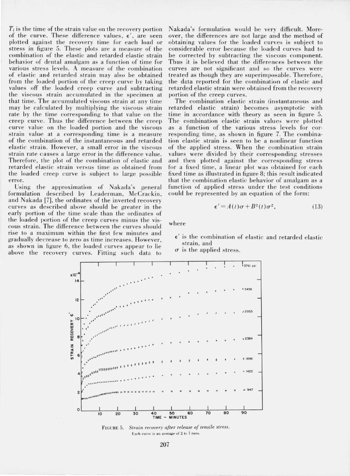
numbe r of different stress levels in figure 3 indicate th at at room temperature amalgam exhibits three differe nt types of viscoelastic phenomena: (1) instantaneous elastic strain , (2) retarded elasti c s train (transient cree p) , and (3) viscous strain (s tead y-stat e creep)_
The viscous strain rate was determined from the loaded portion of the creep curve by takin g the slope of the straight line portion of the curve , and was al so determined from the recovery portion of the cree p curve by dividing the value of the recovery strain (the permanent strain in the specimen) by the total time the load was on the specimen. The viscous strain rates for any given creep curve as calculated from the loaded and recovery portions of the curve were found to agree fairly well as shown in table 1. The log of the viscous strain rate was found to be a linear fun ction
z «
10
B
a:: 6 I-CJ) "L ...... ____ ~. __ ._---"~4'=.~p"-.,-
41-- ••••• "L ,.' .' --~--
2 ~::{:::::~" ••• "."'~" 2959 pi l
o ~: ......... """ I ~ ___ •. _19_0_0"_' _,
I I I o 100 200 300 400 500
TIME - MINUTES
FIGU RE 3. Creep and recovery of amalgam loaded in tension.
- 9 .o,-,--,------r---,---,---,--,---, w I-~ -10.0 Z
::E cr -11.0 w a. z « -12.0
..r cr I-., en
<.!l -13.0 0 en ...J ~
0 <.)
en -14.0
> lL. 0 -15.0 ., <.!l 0 ...J -16.0
6.5 8 .5
LOGe OF STRESS, LOGe (J'
FIGURE 4 . Relationships between viscous strain rate and stress . Straight lines are l eas l -s q~a res fit s of equation log £1- = log K + m log (J' to the dat a, with
e rro rs a ss umed to be in log Er• onl y. Load ed va lues are fro m straight po rtion of cree p curve ; unloaded values are fro m s t rain re maining in s pec ime n aft e r u nload ing a nd recovery.
of the log of the applied stress , as shown in figure 4; thus the viscous strain rate could be related to the applied stress by the following equation :
where
Ev is the viscous s train rate , (J'" is the applied stress , and K and m are constants of the material.
12)
The value of m for amalgam is the value of the slope of th e curve in fi gure 4, while the value of K is the antilog of the viscous strain rate value at a value of applied stress (J'" of 1 psi. For the dental amalgam used in this investigation values for K of 2.85 X 10- HI and 4.98 X 1O - 1~ were obtained from loaded and unloaded data respectively, and values of 3.99 and 3_92 were obtained for m.
The strain developed in amalgam due to the other two phenome na (1) instantaneous elastic strain and (2) retarded s train can be de termined from the strain recovery sin ce these two types of strain are recoverable while the viscous strain is not. Thus , at any given load the strain values taken from the cree p curve after the sample has been unloaded (that is in the recovery portion of the creep curve) are subtracted from the strain value on the creep c urve at the Instant just before unloading of the specimen_ This difference is plotted against recovery time ti = T; - Til where Til is the time at which the specime n was unloaded and
TABLE 1. Viscous strain rates
S train pe r minut e Speci men - run Stress
Ib/in ' Loaded X 1O - ~ a Unloaded X 10 -5 b
4 1- 40- 1 3807 5.65 ' 6. 35 4 1- 4<)- 2 3807 5.98 5.80 39- 4<)- 1 3731 4.92 ' 5.74 39- 4<)- 2 373 1 5.23 5 .08 40- 4<)- 1 3731 7.45 ,. 8.04
43- 35- 1 3458 3. 12 '3.71 43- 35- 2 3458 3.23- 328 43- 35- 3 3458 3.42 3.44 44-30-1 2959 1.92 ;. 1.98 44- 30- 2 2%9 1.68 1.68
44- 30-3 2959 1.14 1.72 4 1- 30- 3 2855 2.84 2.96 44- 25- 4 2465 0.9 1 0.89 35- 25- 1 2375 1.05 ,. 1.33 35- 25- 2 2375 0.98 1.06
35- 25-3 2375 1.03 1.CJ.8 38- 25- 1 2366 1.09 ,. 1.40 38-25-2 2366 0.783 0.821 38- 25- 3 2366 .785. .806 35-20-4 1900 .384
35- 20- 5 1900 .419 0.435 38- 20- 4 1892 .349 .358 35- 15- 6 1425 .111 . 11 3 38- 15- 5 1419 .076 .077 35- 10- 7 950 .031 .034
38- 10- 6 946 .023 .025 38- 10- 7 946 .017 .01 8 35- 05- 8 475 .008 .007
a From slope of s t ra ight po rti on of loaded c reep c urve. h F ro m stra in remaining in s pec imen aft e r unloading and recovery. l' These values incl ude effec ts of stra in harde ning and were not used in calc ulating the
relation between stress and viscous strain rate.
206
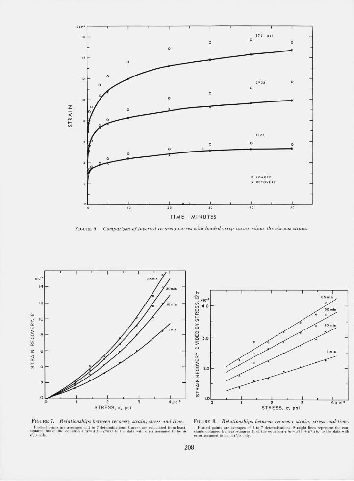
Ti is the time of the s train valu e on the recove ry portion of the c urve. These diffe rence va lues, E', are seen plotted agai nst the recover y time for each load or stress in fi gure 5. These plots are a meas ure of the combination of the elasti c and retarded elastic strain behavior of dental amalgam as a function of time for various s tress levels . A meas ure of the com bin ation of e lastic and retard ed s train ma y also be obtained from the loaded portion of the creep c urve by taking values off the loaded creep curve and subtracting the vi sco us strain accumulated in th e specime n at that time. The accumulated visco us s train at a ny time may be calc ulated by multiplyin g th e viscous s train rate by the time co rresponding to th at value on the cree p curve . Thus th e differe nce betwee n the cree p curve value on the loaded portion and the viscous strain value at a corres ponding time is a meas ure of the co mbination of the instantaneous and retarded elasti c strain . However , a s mall error in the vi sco us strain rate causes a large error in the d i ffe re nce value. Therefore, th e plot of the co mbination of e lastic and retarded e lastic s tra in versus time as obta in ed from the loaded creep c urve is subj ect to la rge possible error.
Using th e approximation of Nakada 's general formulation described by Leaderman , McCrackin, and Nakada [7] , th e ordinates of the inverted recovery c urves as d escribed above should be greater in the early portion of the ti me scale than the ordinates of the loaded portion of the creep c urves minus the vis· cous s train. The diffe re nce between the c urves s hould ri se to a maximum within the firs t few minutes and gradually decrease to zero as time in creases. Howe ver, as show n in fi gure 6, the loaded c urves appear to li e above the recovery c urves. Fittin g s uch dat to
I 1 I I
x10-4
14-
12 l- .. ' x I.·
" ' .' " ' " ....
'" Jr ••••
>- 10 1-' " , '
a:: , , ~ , " , ' ' w "", I" ,
> . , a ", Q " w 8 ", a:: , , Z ~ /' 0 0000 ...
00000 0 0 000
a:: 0000000 ~ 6 , (/) ." .' . . o 0 0 0 0 0 0 0 0
00000000000 0 4 0 0000
0001 ° . . . ... + .......
o .... ++ .......... ++.++ ........ + . 2 DDODOOOOCC CI D 1;1 g D Q 0 0 a 0
~DODDaac:rDO
0 I I I I 10 20 30 40
TIME -
Nakada's formulation would be very difficult. More· over, the differe nces are not large and the method of obtaining valu es for the loaded curves is s ubject to considerable error because the loaded c urves had to be corrected by s ubtracting the viscous co mponent. Thus it is believed that the differences between the curves are not significant a nd so th e c urves were treated as though they are supe rimposable. Therefore, the data reported for the co mbin at ion of elas ti c and retarded elastic strain we re obtain ed from th e recovery portion of the creep curves .
Th e combination elasti c strain (instantaneous a nd retarded elastic strain) beco mes asymptoti c with time in accordance with theory as seen in figure 5. The combination elastic strain valu es we re plotted as a function of the various stress levels for corresponding time, as shown in fi gure 7. The co mbination elastic s train is seen to be a nonlinear function of the applied stress. When the combin ation strain values were divided by their corres pon din g s tresses and the n plotted against the corresponding s tress for a fixed time, a linear plot was ob tain ed for each fixed time as illus trated in fi gure 8; thi s res ult indicated that the combination elastic be havior of amalgam as a fun ction of appli ed stress under the tes t co nditions co uld be represented by a n eq uation of the form:
(13)
where
E' is the co mbination of e lasti c and retarded elastic strai n, and
(T is the applied s tress .
I 1 I ! t 3761 psi
-
· 3458
-
~ 2933
-
-02384
-• 1896
... 1422 -
CI 947 -
I I I I I 50 60 70 80 90 MINUTES
FIGURE 5. Strain recovery aJter release oj tensile stress. Each curve is an averag e of 2 tu 7 run s.
207
o LOADED
X RECOVE RY
10 20 30 40 50
TIME -MINUTES
FIG URE 6. Comparison of inverted recovery curves with loaded creep curves minus the viscous strain.
x 10- 4
14
b -'- 85 min ~ X 10-7
12 CIl 4 .0 CIl
W 30 min
"" 0:: I-
>= 10 CIl 0:: >-W CD > Cl 0 8 w t) Cl 3.0 w :> 0::
is z 6 I min
>-<t 0:: 0:: W I- > CIl 4 0 2.0 t)
W 0::
2 z <t 0:: I-CIl
1.0 2 0
STRESS. CT. psi. cr. psi
FIGURE 7. R elationships between recovery strain, stress and time. FIG URE 8. Relationships between recovery strain, stress and time. Plotted I)oints a re averages of 2 10 7 de termin ations . Curves are ca lculated from least
s qua res fits of the equation E' /u = A{t )+ B2{t )u to the data wit h e rror assum ed 10 be in E'/U on ly.
208
Plotted points are averages of 2 to 7 determinations. Straight lines represent the con· stants obtained by least-squares fit of the equatiun E'/u = A(t) + B2(t)a to the data wi th error assumed to be in E'Ia- only.
A (t) and 8 2 (t) are fun ctions 2 of time but not of stress. The valu e of A(t) for any time value is the interce pt at (]' = 0 of the plot for that time value as shown in fi gure 8 while 8 2 (t ) is the slope of the straight line for that time value . It is also noted in figure 8 th at as a fu nction of stress th e co mbination strain divided by the stress is a s traight lin e for all values of t. This indicated th at ove r all ranges of t , the combination elas ti c s train obeys th e same functional relation to the s tress. Since the reco very c urves were found to be supe rimposable upon the loading curves minus the vi sco us portion, it appeared th at the nonlinear material did not obey the ap proximation of nonlinear generalization pre viously noted [7]. It was then ques tioned whe ther the r etarded behavior of amalgam was trul y nonlin ear or whe ther the non linear behavior co uld be attributed to the geo metry of the specimen be ing observed. Howe ver , longer s pecimens were tested and found to give the sam~ result , also photoelas ti c s pecime ns were made and the stress di stributio n over the area observed was found to be uniform. It is th erefore concluded that the observed nonlin ear behavior of de nta l a malgam is not a geometri c artifact , but an intrin sic phe nome non in the material. The difference between the r ecovery curves and the loadin g c urves minus the viscous portion is given by [7]:
2(]'02 [<P (L~T , T) -<P(T, T)),
where !::l.T is the lime th e specime n was under the load 0(1" F or amalga m, thi s differe nce is found to be zero, so :
<P (!::l.T , T) = <P (T, T) (14)
for creep recovery from equilibrium , i. e. , for !::l.T large. McCrackin [9] has s uggested that thi s co ndition be satisfied b y ass uming that the valu e of <P is only dependent on the value of the least of its argume nts. That is ,
(15)
With thi s co ndition , th e quadratic term of eq (8) is shown in the Appe ndix to redu ce to
(16)
so, eq (8) redu ces to :
fU(T)
E (T) = A(T - 8)d(]' (8) /I 0
(17)
t The notatio n IP-( t ) rathe r tha n B (t ) is use d fo r co ns is ten cy with the fo rm of the notation of Leade rrnan . McC rackin , and Na kada l7J.
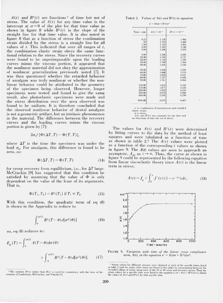
TABLE 2. Values of A(t) and B 2(t) in equation
.. = A (I )o- + 8 '(1)0- '
Time- min A(/ ) X 10- ' 11' ( / ) X 10- "
0.25 1.1 30 1.906 .50 1.1 20 2.468
1.00 1.1 32 3.065 2.00 1.183 3.548 3.00 1.206 3.876
5.00 1.248 4.285 10.00 1.356 4.737 20.00 1.5 18 5. 100 30 .00 1.598 5.364 40.00 1.626 5.636
50.00 1.648 5.839 60.00 1.668 5.970 70.00 1.693 6.031 80.00 1.727 6.050 90.00 1.761 6.064
120.00 1.8 12 6.223 150.00 1.871 6.224 200.00 1.952 6.2 10 300.00 2.074 6.082 600.00 2. 103 6.290
1000.00 2.079 6.497
e ' is c ombinat ion uf in s ta n ta neo us and re ta rded elas tic s t rain .
(I is s tress. A (I ) a nd 8 2(1) are co ns tan ts fo r a ny l ime a nd
a re fUll c t ions of l ime but nul of s tress.
Th e values for A (t ) a nd 8 2 ( t) were dete rr11ined by fittin g curves to th e data by the me thod of least squares a nd were tabulated as a fun c tion of time as shown in tabl e 2.3 Th e A (t ) values were plotted as a fun ction of the co rres pondin g t values as shown in fi gure 9. The A(t) values are seen to approach a n asy mptote, Aas as t ~ 00. Thus, the c urve as s hown in fi gure 9 co uld be re prese nted by the followin g equation from lin ear viscoe last ic th eory s in ce A( t ) is the linear te rm in stress:
A(t) = } + ( X./' (r ) (l-e - t/T) dr , (18) " Jo
2 .2 -
2.0
1.8
~ 1.6
1.4
1.2
/ /
I. 0 :-O--'---;:2::0:-;:O---'-4:;-:0~O::--'---;:6-!:O-;::O---'----:8;;-:O~O;---'---;-:1 O~O;;-::!O TIME - MINUTES
FI GURE 9. Variation with tim.e of the linear creep compliance term, A(t), in the equation e ' = A( l)a- + B '(l)a- 2 •
J Strain va lues fo r diffe re nt stresses we re obt ai ned at each uf the s pecific ti me s li s ted in tab le 2 (a nd for ma ny ot he r l i mes nOI li s te d in the tab le) b y int e rpola tion between the recorded valu es of strain along e ach of the 25 10 30 c ree p a nd recovery curves. Then the s train va lues for a specifi c tjme wc rc fi ll e d tu the e qu a tio n E'/cr = A {t } + B2(t) U to obtai n th e values of A(t) a nd Bt(t) for th at s pec ifi c lime.
209
(20)
A as - A (t) = 1'" J ' (T) e - l i T dT, o
(21)
where
A (t) is the creep com pliance term which is linear in stress,
Jo' is instantaneous elastic compliance, J' (T) is the retarded elastic compliance spectrum
as a function of the retardation time T, and A as is the asymptote value of A (t) as t becomes
very large.
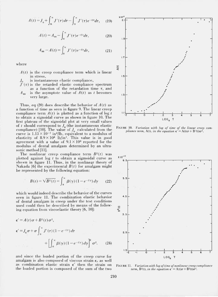
Thus, eq (20) does describe the behavior of A(t) as a function of time as seen in figure 9. The linear creep compliance term A(t) is plotted as a function of log t to obtain a signoidal curve as shown in figure 10. The first plateau of the signoidal plot at very small values of t should correspond to J() (the instantaneous elastic compliance) [10]. The value of Jo calculated from the curve is 1.13 X 10- 7 in 2/lb , equivalent to a modulus of elasticity of 8.9 X 10⁶ Ib/in 2• This value is in good agreement with a value of 9.1 X 10⁶ reported for the modulus of dental amalgam determined by an ultrasonic method [11].
The nonlinear creep , compliance term B2(t) was plotted against log t to .obtain a sigmoidal curve as shown in fi gure 11. Thus, in the nonlinear theory of Nakada [6] the experimental B(t) for amalcfam might be represented by the following equation:
B(t) = v'B2(t)= ( '" {3(y)O-e - IIY )dy (22) JIJ
which would indeed describe the behavior of the curves seen in figure 11. The combination elastic behavior of dental amalgam in creep under the test conditions used could then be described by means of the follow· ing equation from viscoelastic theory [6, 10]:
E' = A (t)(T+ B2(t)o-2 ,
E'=Jo(T+(T !u"' J'(T)O- e- IIT)dT
+[Jo'" !3(y)O-e - I/Y)dyJ (T2. (24)
X 10.7 r--,.---,----,----,--,--,.--...... ----,----,,, 2.1- 1 1 1 I. _
1.9-
1.7 -
1.5 -
1.3 -
, ..... "
, i 0
,.' ..
" ,
1 . 2
LOGe
"
3
T
" " ,;'
:
FIGURE 10. Variation with log oj time oj the linear creep compliance term, A(t), in the equation €'=A(t)a+ B'(t)a'.
X 10- 11
-'" co
6.5.---r--,1--.---,--,.---,---...... --,------..,-,
5.5
4.5
3.5
2 .5
" "
"
,i' •• ~
~" ..
... ...,
-
-
1.5 L---'---... '-----''----'--'--,L--...l'----,~-_,L_ '---:'0-' -2 -I 0 2 3 4 5 6 7
and since the loaded portion of the creep curve for LOGe T
amalgam is also composed of viscous strain Ei' as well as combination elastic strain E ' then the strain on FIGURE 11. Variation with log o/time oJ nonlinear creep compliance the loaded portion is composed of the sum of the two term, 8'(t), in the equation €' = A(t)o-+ 8'(t)0-2.
210
as follows :
E = E ' + Ev. (25)
Thus
Therefore, apply in g both lin ear and nonlinear viscoelas ti c theory to th e experimental behavior of amalgam under the tes t conditions used, a general equation describing the cree p behavior of amalgam as given by eq (26) above is obtained.
Applying the nonlinear gene raljzation of the Boltzmann superposition principle as developed by Nakada [6] , to th e above creep equation for amalga~,. the s tress ·strain curves for various s tress rate conru tlons were calc ulate d for amalgam from the c reep data and compared to th e experim ental stress-s train curves ob tained unde r those conditions. The s tress·s train c urve correspondin g to th e ex pe rimen tal s tress rate was calc ul ated from the following eq uation:
II (AII_I+A II+I_i) ET(ntlt) = L (O"j-O"j _ l) 2
/ = 1
x10J
Ev E,
5.0 '/'
~
4.0 f r '" a.. /
t ;/ ."". V) 3.0
/ /' V) t I ",. UJ
/ 0.:: t f ./ ~ I V) t I /
2.0 ~
+1 / ~
W I
1.0
~ ~
(27)
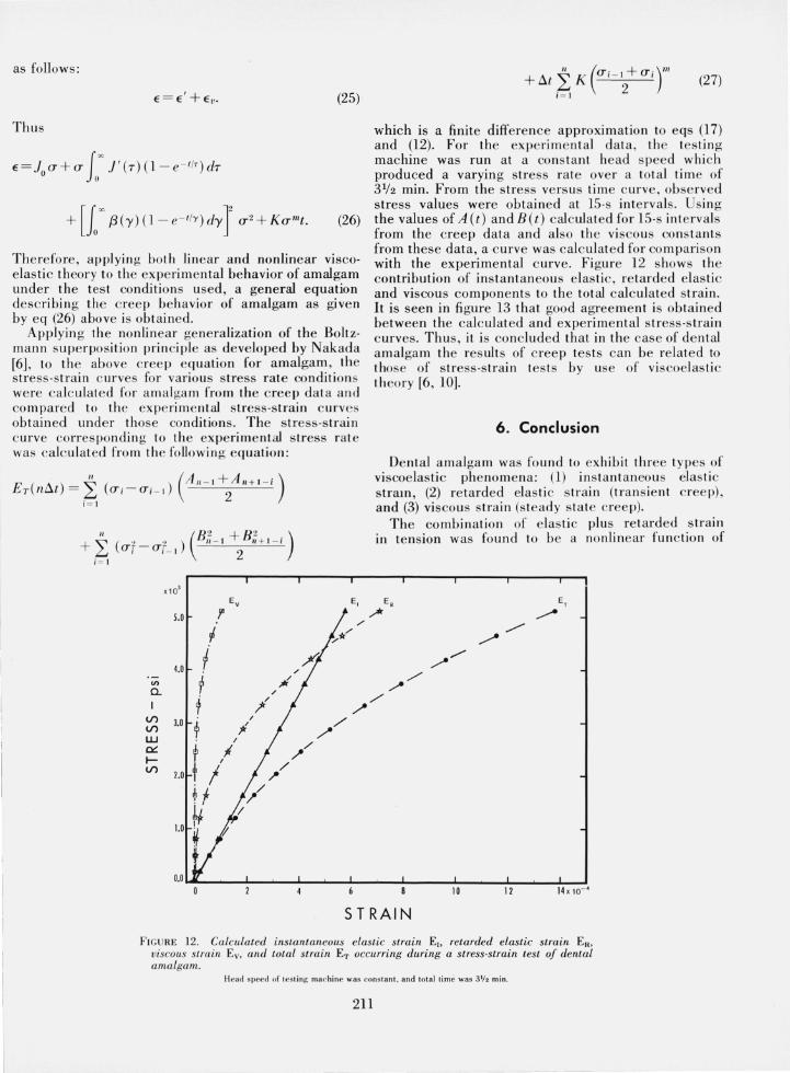
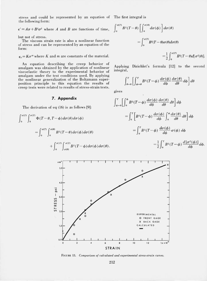
which is a finite differe nce approximation to eqs (17) and (12). For the experim e ntal data, th e testin g machine was run at a cons tant head speed whi ch produced a varying stress ra te over a total ti me of 31/2 min. From the stress versus time curve, observed stress values were obtained at 15·s inte rval s. Us ing the values of A (t) and B(t) calculated for 15·s intervals from the creep data and also th e viscous constants from these data, a c urve was calculated for co mpariso n with the experime ntal c urve. Figure 12 s hows the contribution of instantan eous elas ti c, re tarded elas ti c and viscous components to th e total calc ulated strain. It is seen in fi gure 13 that good agreement is ob tained between the calculated and experime ntal stress-strain curves. Thus, it is co ncluded tha t in the case of dental amalo-a m the res ults of cree p tes ts can be relat ed to those'" of stress-s train tes ts by use of viscoelas ti c theory [6, 10].
6. Conclusion
De ntal amalga m was fou nd to ex hibit three types of viscoelast ic phe nome na: (1) in s ta ntaneous elas ti c stram, (2) retarded elastic s trai n (tran s ie nt c reep), a nd (3) visco us s train (s teady s ta te creep).
The combination of e lastic plus re tarded s train in te nsion was found to be a nonlinear fun ction of
E, ET
/* / /
./ //
/' ~
./'
10 12 14 x 10-'
S T RAI N
F IGURE 12. Calculated instantaneous elastic strain EI> retarded elastic strain ER,
viscous strain Ev, and total strain ET occurring during a stress-strain test of dental amalgam.
I-lead speed of testing machine was constant , and tota l lime was 3If2 min.
211
stress and could be represented by an equation of the following form:
E' =Aa+B2a 2 where A and B are functions of time,
but not of stress. The viscous strain rate is also a nonlinear fun ction
of stress and can be represented by an equation of the form:
Ev= Kalil where K and m are constants of the material.
An equation describing the creep behavior of amalgam was obtained by the application of nonlinear viscoelastic theory to the experimental behavior of amalgam under the test conditions used. By applying the nonlinear generalization of the Boltzmann superposition principle to this equation the results of creep tests were related to results of stress-strain tests.
7. Appendix
The derivation of eq (16) is as follows [9]:
f O'(T) fO' (T) o 0 ¢(T-8,T-¢)da(e)da(¢)
f <T( T) f 0'(9) = 0 0 B2(T-e)da(¢)da(8)
f O'(7') fO'(1') + B2(T-¢)da(¢)da(8).
o 0'(9)
4.0
'" a.
3.0 V) V)
UJ eo:: l-V) 2.0-
1.0-
The first integral is
f O'(T) [fO'(9) ] o B2(T- e) 0 da(4)) dace)
fO'(T)
= B2(T - 8)a( 8)da( e) o
Applying Dirichlet's formula [12] to the second integral,
gives
EXPERIMENTAL
0 FRONT GAGE
X BACK GAGE
CALCULATED
STRA IN
FIGURE 13. Comparison of calculated and experimental stress·strain curves.
212
However , this is the same as th e firs t integral as 8 and cp are dummy variables of integration so the sum of the integral s is
8. References
[1] Rodriguez, M. L. , and Dickson , G., J. Dental Resea rch 28, 441 (1962).
[2) Smith , D. L. , Cau l, H. J., and Sweeney, W. T ., J.A.D.A. 53 677 (1956).
[3) Boltzmann, L. , Sitzbe r, Kg/. Akad. Wiss Wien. 70,275 (1874).
[4] Bland , D. R. , The Theory of Linear Viscoelasticity (Pergamon Press, N.Y., 1960).
[5] Leaderman, H., Elasti c and Cree p Properties of Filamentous Materials and Oth er High Polym er. Textil e Foundation, Washington, D.C. (1943).
[6] Nakada, 0., J. Phys. Soc. J apan 15, 2280 (1960). [7] Leaderman, H., McCrackin , F., and Nakada , 0., Trans. Soc.
Rheology 7, III (1963). [8] Ryge, G., Dickson , G. , Sm ith , D. L. , and Sc hoonover, I. c.,
J.A.D.A. 45,269 (1952). [9] McCrackin, F., Polymers Division, ational Bureau of S tand·
ards, personal communication. [10] Leaderman, H., Rheology 2, p. 14 (Academic Press Inc. N.Y .
1958). ' , , [11] Dickson, G. , and Oglesby, P. L. , 1. Dental Research 46,1475
(1967). [12] Widder, D. V., Advanced Calculus (prenti ce Hall , In c., 1947).
(Paper 72C3- 278)
213