Embed Size (px)
DESCRIPTION
A great document for DC design.
Citation preview

Virtualized Multiservice Data Center (VMDC)Data Center Interconnect (DCI) 1.0Design GuideMarch 5, 2014

CCDE, CCENT, CCSI, Cisco Eos, Cisco Explorer, Cisco HealthPresence, Cisco IronPort, the Cisco logo, Cisco Nurse Connect, Cisco Pulse, Cisco SensorBase,Cisco StackPower, Cisco StadiumVision, Cisco TelePresence, Cisco TrustSec, Cisco Unified Computing System, Cisco WebEx, DCE, Flip Channels, Flip for Good, FlipMino, Flipshare (Design), Flip Ultra, Flip Video, Flip Video (Design), Instant Broadband, and Welcome to the Human Network are trademarks; Changing the Way We Work,Live, Play, and Learn, Cisco Capital, Cisco Capital (Design), Cisco:Financed (Stylized), Cisco Store, Flip Gift Card, and One Million Acts of Green are service marks; andAccess Registrar, Aironet, AllTouch, AsyncOS, Bringing the Meeting To You, Catalyst, CCDA, CCDP, CCIE, CCIP, CCNA, CCNP, CCSP, CCVP, Cisco, theCisco Certified Internetwork Expert logo, Cisco IOS, Cisco Lumin, Cisco Nexus, Cisco Press, Cisco Systems, Cisco Systems Capital, the Cisco Systems logo, Cisco Unity,Collaboration Without Limitation, Continuum, EtherFast, EtherSwitch, Event Center, Explorer, Follow Me Browsing, GainMaker, iLYNX, IOS, iPhone, IronPort, theIronPort logo, Laser Link, LightStream, Linksys, MeetingPlace, MeetingPlace Chime Sound, MGX, Networkers, Networking Academy, PCNow, PIX, PowerKEY,PowerPanels, PowerTV, PowerTV (Design), PowerVu, Prisma, ProConnect, ROSA, SenderBase, SMARTnet, Spectrum Expert, StackWise, WebEx, and the WebEx logo areregistered trademarks of Cisco and/or its affiliates in the United States and certain other countries.
All other trademarks mentioned in this document or website are the property of their respective owners. The use of the word partner does not imply a partnership relationshipbetween Cisco and any other company. (1002R)
THE SOFTWARE LICENSE AND LIMITED WARRANTY FOR THE ACCOMPANYING PRODUCT ARE SET FORTH IN THE INFORMATION PACKET THAT SHIPPED WITH THE PRODUCT AND ARE INCORPORATED HEREIN BY THIS REFERENCE. IF YOU ARE UNABLE TO LOCATE THE SOFTWARE LICENSE OR LIMITED WARRANTY, CONTACT YOUR CISCO REPRESENTATIVE FOR A COPY.
The Cisco implementation of TCP header compression is an adaptation of a program developed by the University of California, Berkeley (UCB) as part of UCB’s public domain version of the UNIX operating system. All rights reserved. Copyright © 1981, Regents of the University of California.
NOTWITHSTANDING ANY OTHER WARRANTY HEREIN, ALL DOCUMENT FILES AND SOFTWARE OF THESE SUPPLIERS ARE PROVIDED “AS IS” WITH ALL FAULTS. CISCO AND THE ABOVE-NAMED SUPPLIERS DISCLAIM ALL WARRANTIES, EXPRESSED OR IMPLIED, INCLUDING, WITHOUT LIMITATION, THOSE OF MERCHANTABILITY, FITNESS FOR A PARTICULAR PURPOSE AND NONINFRINGEMENT OR ARISING FROM A COURSE OF DEALING, USAGE, OR TRADE PRACTICE.
IN NO EVENT SHALL CISCO OR ITS SUPPLIERS BE LIABLE FOR ANY INDIRECT, SPECIAL, CONSEQUENTIAL, OR INCIDENTAL DAMAGES, INCLUDING, WITHOUT LIMITATION, LOST PROFITS OR LOSS OR DAMAGE TO DATA ARISING OUT OF THE USE OR INABILITY TO USE THIS MANUAL, EVEN IF CISCO OR ITS SUPPLIERS HAVE BEEN ADVISED OF THE POSSIBILITY OF SUCH DAMAGES.
NetApp, the NetApp logo, Go further, faster, Data ONTAP, FlexPod, FlexVol, MetroCluster, OnCommand, RAID-DP, SnapMirror, Snapshot, and SyncMirror are trademarks or registered trademarks of NetApp, Inc. in the United States and/or other countries.
Virtualized Multiservice Data Center (VMDC) Data Center Interconnect (DCI) 1.0 Design Guide © 2014 Cisco Systems, Inc. All rights reserved.

Design Guide
C O N T E N T S
C H A P T E R 1 Introduction 1-1
Solution Scope for VMDC DCI 1-2
Use Cases/Services/Deployment Models 1-3
Key Solution Benefits 1-5
Audience 1-6
Related CVD Guides 1-7
C H A P T E R 2 System Overview 2-1
Mapping Applications to Business Criticality Levels 2-2
Active-Active Metro Design 2-5
Active-Backup Metro/Geo Design 2-6
VMDC DCI Supports Multiple Design Options 2-8
Top Level Use Cases 2-9
Design Parameters for Active-Active Metro Use Cases 2-9
Design Parameters for Active-Standby Metro/Geo Use Cases 2-10
Solution Architecture 2-12
Active-Active Metro Design 2-12
Active-Backup Metro/Geo Design 2-13
System Components 2-14
C H A P T E R 3 VMDC DCI Design 3-1
Data Center Fabric Design 3-3
FabricPath Terminology 3-4
FabricPath Topologies 3-4
FabricPath “Typical Data Center” Model 3-4
Layer 3 Design 3-5
Services 3-6
Tenancy Models 3-8
LAN Extension Options for Multi-Site Topologies 3-9
OTV Design Considerations 3-11
Nexus 1000v Virtual Switch Metro Extensions 3-15
Compute 3-17
iVirtualized Multiservice Data Center (VMDC) Data Center Interconnect (DCI) 1.0

Contents
Storage 3-18
Storage Design Constraints 3-19
Zero RPO and Near-Zero RTO Using NetApp MetroCluster 3-19
MetroCluster Design with FCoE Frontend 3-22
Network Connectivity for Storage Access 3-23
SAN Design Details 3-24
Datastore Layout 3-24
Less Stringent RTO/RPO Protection Using NetApp SnapMirror 3-25
VMware Redundancy and Workload Mobility Options 3-27
VMware Workload Mobility Design 3-32
C H A P T E R 4 System Level Design Considerations 4-1
System Scale Considerations 4-1
System Availability 4-3
Security 4-4
Manageability 4-5
Service Assurance and Monitoring 4-5
Traffic Engineering 4-5
MAC Pinning 4-7
QoS Framework 4-8
Classification and Marking 4-9
Queuing, Scheduling, and Dropping 4-10
Shaping and Policing 4-12
C H A P T E R 5 Infrastructure Management Tools 5-1
UCSM 5-1
VNMC 5-2
DCNM 5-2
VMware vCenter 5-3
NetApp OnCommand System Manager 5-4
iiVirtualized Multiservice Data Center (VMDC) Data Center Interconnect (DCI) 1.0
Design Guide

Virtualized Multiservice Data CDesign Guide
C H A P T E R 1
IntroductionThe Cisco Virtualized Multiservice Data Center (VMDC) system provides design and implementation guidance for enterprises deploying private cloud services, and for Service Providers (SPs) building public and virtual private cloud services. The Virtual Multi-Service Data Center (VMDC) is Cisco’s reference architecture for cloud deployments and has been widely adopted by a large number of service providers and enterprises worldwide. VMDC integrates Cisco and third-party products across the cloud computing ecosystem into a validated end-to-end system that customers can deploy with confidence.
Figure 1-1 Cisco Cloud Systems Foundation
2952
05
IaaS, SaaS, NfV, HCS, VDI, Hybrid Solutions, DRaaS(including software to automate and orchestrate the application)
SDN Controllers/Infrastructure Orchestration
Clo
ud S
ervi
ce A
ssur
ance
(C
LSA
)
Infrastructure Abstraction/Management Software
Data Center Interconnect
Data Center 1 Data Center 2
Scalable, Multi-Tenant L2/L3 DataCenter Networking
Security Features
IntegratedCompute Stacks(Vblock, FlexPod,
etc.)
L4-7 Services
IntegratedCompute Stacks(Vblock, FlexPod,
etc.)
Scalable, Multi-Tenant L2/L3 DataCenter Networking
Security Features
IntegratedCompute Stacks(Vblock, FlexPod,
etc.)
L4-7 Services
IntegratedCompute Stacks(Vblock, FlexPod,
etc.)
CloudInfrastructure
CloudOrchestration and
Management(CLO)
Cloud EnabledApplicationsand Services
VirtualMulti-Service
Data Center(VMDC)
Data Center Interconnect (DCI) refers to underlying technologies used to connect geographically dispersed data centers to support Business Critical operations. This VMDC DCI solution provides validated guidelines for cloud data center connectivity across metro distances (less than 200 km) and geo distances (more than 200 km). This VMDC DCI solution enables critical business operations including:
• Application business continuity across multiple data center sites
• Application disaster recovery and avoidance across multiple data center sites
• Application geo-clustering and load balancing across multiple data center sites
• Complete workload mobility across multiple data center sites
• Operations functions across multiple data center sites including workload rebalancing, Maintenance operations, and consolidation of workloads
1-1enter (VMDC) Data Center Interconnect (DCI) 1.0

Chapter 1 IntroductionSolution Scope for VMDC DCI
Solution Scope for VMDC DCIThe VMDC DCI solution provides metro and geo extensions that enable the interconnection of geographically diverse Cloud data centers. The VMDC DCI system enables elasticity, mobility, and recovery of applications and workloads from one physical data center to another with minimal disruption to the application. Application workloads consume a range of physical and virtual resources across the cloud, as described in Figure 1-2. If an application or workload moves between sites, the application environment must also adjust to the new location. VMDC DCI extends the application environment across sites to enable workload elasticity and more flexible deployment models. The application environment spans a number of critical elements including multi-site WAN connections, data center fabrics, L4-L7 services, hypervisors and virtual switching, compute resources, and storage resources. VMDC DCI extends these elements to unlock a range of business functions including business continuity, disaster recovery and avoidance, workload mobility, active-active data centers, and support of application geo-clusters. VMDC DCI also supports multi-site functions required by operations teams including workload rebalancing between sites, site migrations, and consolidation of workloads between sites.
Figure 1-2 Application Centric approach to Data Center Interconnect
2952
06VMDC DCI EXTENDS THE APPLICATION ENVIRONMENT ACROSS MULTIPLE SITES,SUPPORTING PHYSICAL AND VIRTUAL ELEMENTS
DC FabricNetworking
L4–L7Services
Multi DCWAN and Cloud
Compute StorageHypervisorsand VirtualNetworking
• Applications consume resources across the Cloud DC infrastructure
• Critical IT Use Cases including Business Continuity and Workload Mobilityacross the Cloud, impact each element of the Application Environment
• If an Application moves between sites, each element of the ApplicationEnvironment must also adjust to the new location
• VMDC DCI extends the Application Environment between Geographic sites
The VMDC DCI system provides design guidance on how the data center infrastructure can more easily support workload mobility and business continuity within Private and Public Clouds. This Cisco VMDC solution addresses how DCI extensions across metro/geo data centers directly impact each element of the application environment. The Application environment within Public and Private Cloud data centers includes many elements. Each element participates in the validated DCI design, providing much needed capabilities to support application mobility between geographic sites. VMDC DCI extends the application environment as described in Figure 1-3, across each element listed below:
• Redirection of external users to the appropriate site.
• L2 extensions between sites to enable workload mobility and the preservation the application's IP addressing.
• Extending data center fabric functions between sites including tenancy, network containers, traffic QoS, and bandwidth reservation.
• Extending L4-L7 Services between sites including service chaining for both physical or virtual services.
• Multi-site hypervisor features supporting workload migrations, extended clusters, and high availability for VMware and Microsoft Hyper-V environments.
• Distributed Virtual switching spanning multiple sites.
1-2Virtualized Multiservice Data Center (VMDC) Data Center Interconnect (DCI) 1.0
Design Guide

Chapter 1 IntroductionUse Cases/Services/Deployment Models
• Distributed Compute environment supporting integrated PoDs, with port and security profiles spanning multiple sites.
• Distributed Storage environment including NAS/SAN extensions, virtual volumes, storage fabric, and data replication across multiple sites.
• Service Orchestration, provisioning, and management of the application environment and infrastructure.
Figure 1-3 VMDC DCI Extends Application Environment Across Multiple Sites
Application Environment
DC FabricNetworking
L4–L7Services
Multi DCWAN and Cloud
Compute StorageHypervisorsand VirtualNetworking
DC FabricNetworking
L4–L7Services
Multi DCWAN and Cloud
Compute StorageHypervisorsand VirtualNetworking
2952
07
APPLICATION ENVIRONMENT INCLUDES PHYSICAL AND VIRTUAL COMPNENTS
Application Environment
Site 1
Site 2
Data Center InterconnectVMDC
Ser
vice
Orc
hest
ratio
n,P
rovi
sion
ing,
and
Man
agm
ent
Use Cases/Services/Deployment ModelsThe three site deployment model described in Figure 1-4 was used as a basis for the VMDC DCI design. This model integrates two data centers at a metro or regional distance of less than 200 km and 10 ms Round Trip Time (RTT). Metro data centers have the ability to operate as a single virtual data center spanning a metro distance, supporting active-active scenarios, live application migrations, and stretched cluster designs. The third data center is at a geo Distance of greater than 200 km and more than 10 ms RTT. The third data center provides a many-to-one recovery capability to a site spanning a much longer distance. The distance limitations to the third site typically force an active-standby operational model and cold workload migrations between independent sites.
1-3Virtualized Multiservice Data Center (VMDC) Data Center Interconnect (DCI) 1.0
Design Guide

Chapter 1 IntroductionUse Cases/Services/Deployment Models
Figure 1-4 VMDC DCI Validates aThree Site Data Center Model
The metro data centers support DCI features that enable the following business critical use cases:
• Live workload mobility between metro data centers.
• Cold workload mobility between metro data centers.
• Stretched clusters and stateful services between metro data centers.
• Active-Active, Active-Standby, and load balanced applications designs between metro data centers.
• Regional disaster recovery between metro data centers.
• Workload rebalancing, operations maintenance activities, and consolidation of live or cold workloads between metro data centers.
• Site migrations of active workloads between metro data centers.
The geo data center located at a further distance supports DCI features that enable the following business critical use cases:
• Cold workload mobility between metro/geo data centers.
• Certain Live Workload Mobility scenarios that support larger network latency between metro/geo data centers.
• Active-Standby and load balanced application designs between metro/geo data centers.
• National disaster recovery between metro/geo data centers.
• Workload rebalancing, operations maintenance activities, and consolidation of cold workloads between metro/geo data centers.
• Site migrations of cold workloads or halted workloads between metro/geo sites.
VMDC DCI enables a range of critical business functions and including business continuity and workload mobility (Figure 1-5).
1-4Virtualized Multiservice Data Center (VMDC) Data Center Interconnect (DCI) 1.0
Design Guide

Chapter 1 IntroductionKey Solution Benefits
Figure 1-5 VMDC DCI Enables a Range of Critical Business Functions
2952
09
THE APPLICATION ENVIRONMENT IS EXTENDED TO SUPPORT MULTI-SITE USE CASES
DC FabricNetworking
L4–L7Services
Multi DCWAN and Cloud
Compute StorageHypervisorsand VirtualNetworking
Site 1 Site 2Business ContinuityWorkload MobilityDisaster Recovery
Load Balanced WorkloadsOperations MaintenanceOperations Rebalancing
Application Clusters
DCI Use Cases
VMDC DCI infrastructure was validated with a range of products and features, needed to extend the application environment across multiple sites. The summary of infrastructure components is provided in Figure 1-6. Other product options are also available, and are described throughout this document.
Figure 1-6 Infrastructure Components Summary
2952
10
CLOUD INFRASTRUCTURE INTEGRATES PHYSICAL AND VIRTUAL COMPONENTS REQUIRED BY BUSINESS CRITICAL APPLICATIONS
DC FabricNetworking
L4–L7Services
WAN Connectivity• IP Internet Access• ASR-9K, ASR-1K
L3 Routing and IGP• OSPF and ISIS
Data Center Interconnect• Overlay Transport Virtualization (OTV)
Data Center Fabric• FabricPath• Nexus 7K, 6K, 5K, 2K
Fabric Services• Tenancy • Secure Segmentation (VRF, VLAN)• Traffic QoS
Physical and Virtual Services• Firewalls (Cisco ASA) • Load Balancer (Citrix SDX)• Virtual Service Gateway (VSG)• Expanded Palladium Network Container
Hypervisors• VMware vSphere• Microsoft Hyper-V
Hypervisor Services• Live and Cold Application Migrations• Extended Clusters• VM High Availability and Recovery Services• Site Affinity Services
Virtual Switching• Nexus1000v
Unified Compute System (UCS)• B-Series Blade Servers• C-Series Rack Servers• Physical and Virtual Interfaces• Port and Security Profiles
Integrated PoDs• FlexPod
Storage • NetApp
Storage Fabrics• FCoE and FC• 10GE• DWDM & IP Extensions
Data Replication• Synchronous (NetApp MetroCluster)• Asynchronous (NetApp SnapMirror) • Synchronous (Microsoft Shared Nothing Live Migration)• Asynchronous (Microsoft Replica)
Multi DCWAN and Cloud
Compute StorageHypervisorsand VirtualNetworking
Key Solution BenefitsThe VMDC DCI solution incorporates a wide range of Cisco cloud innovations and Partner products. These products are integrated within the Cisco Validated Design (CVD). The DCI solution provides compelling benefits to Public and Private Cloud Providers:
• Simplify the DCI Design Process for Operations Teams—Interconnecting Cloud Data Centers involves many infrastructure elements and application components that provide critical business services. The VMDC DCI design provides a validated reference design that significantly reduces risk of implementation using Cisco’s latest product innovations and partner products. This VMDC DCI design builds upon previous VMDC releases that have been extensively validated and widely deployed by Enterprises and Service Providers worldwide. The validated VMDC DCI design enables Public and Private Cloud Providers to deploy DCI functions with confidence.
1-5Virtualized Multiservice Data Center (VMDC) Data Center Interconnect (DCI) 1.0
Design Guide

Chapter 1 IntroductionAudience
• End-to-end Validation of the Application Environment—The VMDC DCI solution delivers validated guidelines across the end-to-end layers of the cloud data center. The DCI design spans different sites and addresses each element of the Application environment including WAN connections, LAN extensions, tenancy, network containers, distributed virtual switching, and L4-L7 services; as well as traditional functions such as hypervisor vMotion and storage replication. This is a true DCI solution that directly addresses each element of the Application environment.
• Validates 2 of the most used DCI Design Options—VMDC DCI validates the most common design options to achieve 2 major Recovery Point Objective (RPO) and Recovery Time Objective (RTO) targets. The first design option enables the movement of applications, their date, their services, and network containers to support near zero RPO/RTO for the most business critical functions. Less business critical applications can be mapped to a second design option to achieve RPO/RTO targets of 15 minutes or more.
• Minimal Disruption to the Application—VMDC DCI allows operators to preserve IP addresses of moved applications, their services, and network container between sites.
• Reduction in CAPEX/OPEX for DCI Deployments—VMDC DCI helps customers align the correct DCI design to achieve the selected application RPO/RTO targets. The most stringent recovery targets typically require the highest CAPEX/OPEX. VMDC DCI provides a framework to map Applications to different Criticality Levels, and then select the most cost effective option that meets application requirements.
• Planned Usage of Recovery Capacity—Recovery capacity at remote sites can be used for other applications during “normal operations” and “reclaimed” as needed by Operations Teams during recovery events. This “Reuse-Reclaim” design strategy allows for planned utilization of extra capacity and many-to-one resource sharing, reducing CAPEX/OPEX.
• DCI Use Cases Validated with Business Applications—VMDC DCI utilized traditional business applications across each workload migration and business continuity use case. The test applications include Oracle database servers, Microsoft SharePoint and SQL, for single tier and multi-tier test applications.
• Multiple Hypervisors supported—Both VMware and Microsoft Hyper-V environments are supported. Microsoft Hyper-V design guidance is provided as a separate addendum.
• Product Performance Measured across DCI Use Cases—The performance of Cisco products and Partner Products used in VMDC DCI was measured and documented across metro/geo environments. Performance limitations, design recommendations, and configurations are provided for Cisco and Partner products.
• Operational Simplicity—This VMDC DCI release utilizes cloud service orchestration and resource provisioning products from Cisco and Cisco partners to support multi-site environments. Automated provisioning of cloud assets significantly simplifies operations, especially across multi-site designs.
AudienceThis guide is intended for, but not limited to, system architects, network design engineers, system engineers, field consultants, advanced services specialists, and customers who want to understand how to deploy a public or private cloud data center infrastructure. This guide assumes that the reader has a basic understanding of enterprise and SP network designs and data center architectures.
1-6Virtualized Multiservice Data Center (VMDC) Data Center Interconnect (DCI) 1.0
Design Guide

Chapter 1 IntroductionRelated CVD Guides
Related CVD GuidesA brief description of previous VMDC System Releases is provided below for reference.
VMDC 2.x System Releases
In the data center portion of the architecture, VMDC 2.X designs were centered on traditional hierarchical infrastructure models incorporating leading Cisco platforms and Layer 2 (L2) resilience technologies such as Virtual Port Channel (vPC), providing network containers or tenancy models of different sizes and service profiles, with necessary network based services and orchestration and automation capabilities to accommodate the various needs of cloud providers and consumers.
VMDC 3.x System Releases
VMDC 3.X systems releases introduced Cisco FabricPath for intra-DC networks, as an optional L2 alternative to a hierarchical vPC-based design. FabricPath removes the complexities of Spanning Tree Protocol (STP) to enable more extensive, flexible, and scalable L2 designs. Customers leveraging VMDC reference architecture models can choose between vPC-based and FabricPath-based designs to meet their particular requirements.
VMDC Virtual Services Architecture (VSA) System Releases
VMDC VSA is the first VMDC release dealing specifically with the transition to NFV (Network Function Virtualization) of IaaS network services in the data center. Such services comprise virtual routers, virtual firewalls, load balancers, network analysis and WAN optimization virtual appliances.
The VMDC VSA release focuses mainly on public provider use cases, building a new logical topology model around the creation of virtual private cloud tenant containers in the shared data center infrastructure. Future releases will incorporate additional cloud consumer models specific to enterprise and private cloud use cases. In particular, future releases will address hybrid consumer models, comprising physical and virtual service appliances, used together as part of a per-consumer or per-tenant service set. These can be implemented on either a 2.X (classical Ethernet) or 3.X (FabricPath) VMDC infrastructure. However, the initial VMDC VSA release will focus on fundamental implications of an all-virtual approach, and a simple FabricPath data center topology previously validated in VMDC 3.0.
1-7Virtualized Multiservice Data Center (VMDC) Data Center Interconnect (DCI) 1.0
Design Guide

Chapter 1 IntroductionRelated CVD Guides
1-8Virtualized Multiservice Data Center (VMDC) Data Center Interconnect (DCI) 1.0
Design Guide

Virtualized Multiservice Data CDesign Guide
C H A P T E R 2
System OverviewInterconnecting Cloud Data Centers can be a complex undertaking for Enterprises and SP’s. Enabling business critical applications to operate across or migrate between metro/geo sites impacts each Tier of the Cloud Data Center as described in Figure 2-1. Customers require a validated end-to-end DCI solution that integrates Cisco’s best in class products at each tier, to address the most common Business Continuity and workload mobility functions. To support workloads that move between geographically diverse data centers, VMDC DCI provides Layer 2 extensions that preserve IP addressing, extended tenancy and network containers, a range of stateful L4-L7 services, extended hypervisor geo-clusters, geo-distributed virtual switches, distributed storage clusters, different forms of storage replication (synchronous and asynchronous), geo-extensions to service orchestration tools, IP path optimization to redirect users to moved VMs and workloads, and finally, support across multiple hypervisors. The cumulative impact of interconnecting data centers is significant and potentially costly for SPs and Enterprises. Lack of technical guidance and best practices for an “end-to-end” business continuity solution is a pain point for customers that are not staffed to sift through these technical issues on their own. In addition, multiple vendors and business disciplines are required to design and deploy a successful business continuity and workload mobility solution. VMDC DCI simplifies the design and deployment process by providing a validated reference design for each tier of the Cloud Data Center.
Figure 2-1 Extending Cloud Data Centers Across InfrastructureTiers
2952
11
Data Center 1
Services andContainers
IntegratedComputeStacks
VirtualSwitching
Virtual StorageVolumes
Storage andFabric Extensions
ManagementInfrastructureand Orchestration
ManagementInfrastructureand Orchestration
WAN Edge/DCI
Switching Fabric
VMware ESX
VM VM VM
Data Center 2
Services andContainers
IntegratedComputeStacks
VirtualSwitching
Virtual StorageVolumes
Storage andFabric Extensions
WAN Edge/DCI
Route Optimization
Switching Fabric
VMware ESX
VM VM VM
Path Optimization(LISP/DNS/Manual)
Layer 2 Extension(OTV/VPLS/E-VPN)
Stateful Services(FW/SLB/IPsec/VSG)
CiscoProducts
PartnerProducts
Distributed Virtual Switch(FW/SLB/IPsec/VSG)
VMware and Hyper-VUCS/Geo-Clusters/Mobility
Storage FederationMDS Fabric and FCoE
Tenancy and QoS
Distributed Virtual Volumes
OrchestrationContainer
The VMDC DCI design uses the following definitions to assess the overall cost of a recovery time resulting from workload mobility or a recovery plan:
2-1enter (VMDC) Data Center Interconnect (DCI) 1.0

Chapter 2 System OverviewMapping Applications to Business Criticality Levels
• Business Continuity—Processes to ensure that essential Business functions can continue during and after an outage. Business continuance seeks to prevent interruption of mission-critical services, and to reestablish full functioning as swiftly and smoothly as possible.
• Recovery Point Objective (RPO)—Amount of data loss that’s deemed acceptable, defined by application, in the event of an outage. RPO can range from zero (0) data loss to minutes or hours of data loss depending on the criticality of the application or data.
• Recovery Time Objective (RTO)—Amount of time to recover critical business processes to users, from initial outage, ranging from zero time to many minutes or hours.
• Recovery Capacity Objective (RCO)—Additional capacity at recovery sites required to achieve RPO/RTO targets across multi-site topologies. This may include many-to-one site recovery models and planned utilization of recovery capacity for other functions
• Metro Distance—Typically less than 200 km and less than 10 ms RTT
• Geo Distance—Typically greater than 200 km and less than 100 ms RTT
The Business Criticality of an application will define an acceptable RPO and RTO target in the event of a planned or unplanned outage. (Figure 2-2)
Figure 2-2 RPO and RTO Definitions
Achieving necessary recovery objectives involves diverse operations teams and an underlying Cloud infrastructure that has been built to provide business continuity and workload mobility. Each application and infrastructure component has unique mechanisms for dealing with mobility, outages, and recovery. The challenge of an end-to-end cloud data center solution is to combine these methods in a coherent way so as to optimize the recovery/mobility process across metro and geo sites, and reduce the overall complexity for operations teams. This is the ultimate goal of the VMDC DCI solution.
Mapping Applications to Business Criticality LevelsA critical component of a successful DCI strategy is to align the business criticality of an application with a commensurate infrastructure design that can meet those application requirements. Defining how an application or service outage will impact Business will help to define an appropriate redundancy and mobility strategy. A critical first step in this process is to map each application to a specific Critically Level as described in Figure 2-3.
2-2Virtualized Multiservice Data Center (VMDC) Data Center Interconnect (DCI) 1.0
Design Guide

Chapter 2 System OverviewMapping Applications to Business Criticality Levels
Figure 2-3 Application Criticality Levels
2952
14
Any outage results in immediate cessation of a primary function,equivalent to immediate and critical impact to revenue generation,brand name and/or customer satisfaction; no downtime is acceptableunder any circumstances
Any outage results in immediate cessation of a primary function, equivalent to major impact to revenue generation, brand name and/or customer satisfaction
Any outage results in cessation over time or an immediate reduction of a primary function, equivalent to minor impact to revenue generation, brand name and/or customer satisfaction
A sustained outage results in cessation or reduction of a primaryfunction
A sustained outage has little to no impact on a primary function
Each Application is mapped to a specific level… Cloud Data Centers should accommodate all levels… Cost is important factor
MissionImperative
MissionCritical
BusinessCritical
BusinessOperational
BusinessAdministrative
C1RTO/RPO
0 t0 80mins
LowestRTO/RPO
Typical AppDistribution
20% of Apps
20% of Apps
40% of Apps
20% of Apps
HighestRTO/RPO
RTO/RPO1 to 5 hrs
CriticalityLevels
Term Impact Description
C2
C3
C4
C5
Industry standard application criticality levels range from Mission Imperative (C1) in which any outage results in immediate cessation of a primary business function, therefore no downtime or data loss is acceptable, to Business Administrative (C5) in which a sustained outage has little to no impact on a primary business function. Applications representing more Business Critical functions (C1-C3) typically have more stringent RTO/RPO targets than those toward the bottom of the spectrum (C4-C5). In addition, most SP and Enterprise Cloud Providers have applications mapping to each Criticality Level. A typical Enterprise distribution of applications described above shows roughly 20% of applications are Mission Imperative and Mission Critical (C1, C2) and the remainder of applications fall into lower categories of Business Critical, Business Operational, and Business Administrative (C3-C5). The VMDC Cloud Data Center must therefore accommodate different levels and provide Business Continuity and workload mobility capabilities to support varied RPO/RTO targets.
It important to note that even a relatively outage (less than one hour) can have a significant business impact to enterprises and service providers. Figure 2-4 describes the typical Recovery Point Objective (RPO) requirements for different enterprises. In this study, 53% of Enterprises will have significant revenue loss or business impact if they experience an outage of just one hour of Tier-1 data (Mission Critical data). In addition, 48% of these same enterprises will have a significant revenue loss or business impact if they experience an outage of less than 3 hours of Tier-2 data (Business Critical data). Even tighter RPO requirements are applicable to SP Cloud Providers. Enterprise and SP Cloud Providers have a strong incentive to implement Business Continuity and workload mobility functions to protect critical workloads and support normal IT operations. VMDC DCI provides a validated framework to achieve these goals within Private Clouds, Public Clouds, and Virtual Private Clouds.
2-3Virtualized Multiservice Data Center (VMDC) Data Center Interconnect (DCI) 1.0
Design Guide

Chapter 2 System OverviewMapping Applications to Business Criticality Levels
Figure 2-4 Typical Enterprise RPO Requirements1
VMDC DCI implements a reference architecture that meets two of the most common RPO/RTO targets identified across Enterprise Private Clouds and SP Private/Public Clouds. The two RPO/RTO target use cases are described in Figure 2-5. The first case covers an RTO/RPO target of 0 to 15 minutes which addresses C1 and C2 criticality levels. Achieving near zero RTO/RPO requires significant infrastructure investment, including synchronous storage replication, Live VM migrations with extended clusters, LAN extensions, and metro services optimizations. Achieving near zero RTO/RPO typically requires 100% duplicate resources at the recovery site, representing the most capital intensive business continuity/workload mobility option. The second use case covers an RPO/ RTO target of more than 15 minutes which addresses Critically Levels C3 and C4. Achieving a 15 minute target is less costly, less complex, and can utilize a many-to-one resource sharing model at the recovery site.
Figure 2-5 Validated RPO/RTOTargets
2952
15
Any outage results in immediate cessation of a primary function,equivalent to immediate and critical impact to revenue generation,brand name and/or customer satisfaction; no downtime is acceptableunder any circumstances
Any outage results in immediate cessation of a primary function, equivalent to major impact to revenue generation, brand name and/or customer satisfaction
Any outage results in cessation over time or an immediate reduction of a primary function, equivalent to minor impact to revenue generation, brand name and/or customer satisfaction
A sustained outage results in cessation or reduction of a primaryfunction
A sustained outage has little to no impact on a primary function
VMDC DCI will focus on twocommon RTO/RPO Targets
MissionImperative
MissionCritical
BusinessCritical
BusinessOperational
BusinessAdministrative
C1RTO/RPO
0 t0 80mins
LowestRTO/RPO
TypicalCost $
100%Duplicate
Resources,2x Cost
Multiplier(Most Costly)
HighestRTO/RPO
RTO/RPO15+ mins
CriticalityLevels
Term Impact Description
C2
C3
C4
C5
Many-to-OneResourceSharing.
Lower CostMultiplier
(Less Costly)
1. Source: Enterprise Strategy Group, 2012
2-4Virtualized Multiservice Data Center (VMDC) Data Center Interconnect (DCI) 1.0
Design Guide

Chapter 2 System OverviewActive-Active Metro Design
To cover both of these recovery targets, the VMDC DCI design must support two operational models. The first operational model, Active-Active metro design, is derived from two physical sites spanning a metro distance, operating as a single Logical Data Center. The second operational model represents a more traditional Active-Backup metro/geo Design, where two independent data centers provide recovery and workload mobility functions across both metro and geo distances. A brief description of both VMDC DCI options is provided below.
Active-Active Metro DesignThe active-active metro design is described in Figure 2-6. This model provides DCI extensions between two metro sites, operating together as a single Logical Data Center. This design accommodates the most stringent RTO/RPO targets for Business Continuity and Workload Mobility. This model supports applications that require live workload mobility, near zero RTO/RPO, stateful services, and a synchronous storage cluster across a metro distance.
Figure 2-6 Active-Active Metro Design
2952
16
Data Center 1
Services andContainers
IntegratedComputeStacks
VirtualSwitching
Virtual StorageVolumes
Storage andFabric Extensions
ManagementInfrastructureand Orchestration
WAN Edge/DCI
Switching Fabric
VMware ESX
VM VM VM
Data Center 2
Services andContainers
IntegratedComputeStacks
VirtualSwitching
Virtual StorageVolumes
Storage andFabric Extensions
ManagementInfrastructureand Orchestration
WAN Edge/DCI
Route Optimization
Switching Fabric
VMware ESX
VM VM VM
Maintain Stateful Servicesand Network Containers
Synchronous StorageReplicatioin
Live Workload MobilityExtended Clusters
Storage FederationMDS Fabric and FCoE
Extended OperationalDomain
These Sites are Operating as ONE Logical Data Center
Extend Tenancy and QoS
LAN Extensions
Distributed Virtual Switching
Applications mapped to this infrastructure may be distributed across metro sites and also support Live Workload mobility across metro sites. Distributed applications and Live Workload Mobility typically requires stretched clusters, LAN extensions, and synchronous storage replication, as described in Figure 2-7. DCI extensions must also support Stateful L4-L7 Services during workload moves, preservation of network QoS and tenancy across sites, and virtual switching across sites. A single Operational domain with Service Orchestration is typically used to manage and orchestrate multiple data centers in this model.
2-5Virtualized Multiservice Data Center (VMDC) Data Center Interconnect (DCI) 1.0
Design Guide

Chapter 2 System OverviewActive-Backup Metro/Geo Design
Figure 2-7 Distributed Clusters and Live Workload Mobility
The key VMDC DCI design choices for the Active-Active metro design are described in Figure 2-8.
Figure 2-8 Active-Active Metro Design Choices
Move an “ACTIVE” Workload across Metro Data Centers while maintaining Stateful ervices 2952
18
Data Center 1
Services andContainers
IntegratedComputeStacks
VirtualSwitching
Virtual StorageVolumes
Storage andFabric Extensions
ManagementInfrastructureand Orchestration
WAN Edge/DCI
Switching Fabric
VMware ESX
VM VM VM
VMDC DCI Design Choices
• External Path Re-direction thru Manual configuration or RHI• Forced routing re-convergence to new site
• OTV LAN Extension, Preserve IP Addressing of Applications• IP WAN Transport with 10ms RTT across Metro distance
• VMDC 3.0 FabricPath (Typical Design) with Multi-Tenancy• Palladium Network Container
• Stateful Services between sites• Citrix SDX SLB at each site (no Metro extension)• ASA 5500 FW Clustering at each site (no Metro extension)
• Stretched ESX Clusters and Server Affinity• VMware Live vMotion across Metro sites• Distributed vCenter spanning Metro sites• Single and Multi-Tier Application migration strategy
• Nexus 1000v with VSMs and VEMs across Metro sites• Service and Security Profiles follow Application VMs• Different Nexus 1000v’s mapped to Application Domains as needed
• Virtual volumes follow VM
• NetApp MetroCluster Synchronous Storage Replication• ONTAP 8.1 Fabric MetroCluster, 160 Km long haul link (DWDM)• FCoE to compute stack, Cisco MDS FC Switching for data
replication
• Replicate Service Container to new site to support Mobile VM• Virtual Management Infrastructure support across Metro
Route Optimization
Path Optimization(LISP/DNS/Manual)
Layer 2 Extension(OTV/VPLS/E-VPN)
Stateful Services(FW/SLB/IPsec/VSG)
CiscoProducts
PartnerProducts
Distributed Virtual Switch(FW/SLB/IPsec/VSG)
VMware and Hyper-VUCS/Geo-Clusters/Mobility
Storage ClustersMDS Fabric and FCoE
Tenancy and QoS
Distributed Virtual Volumes
OrchestrationContainer
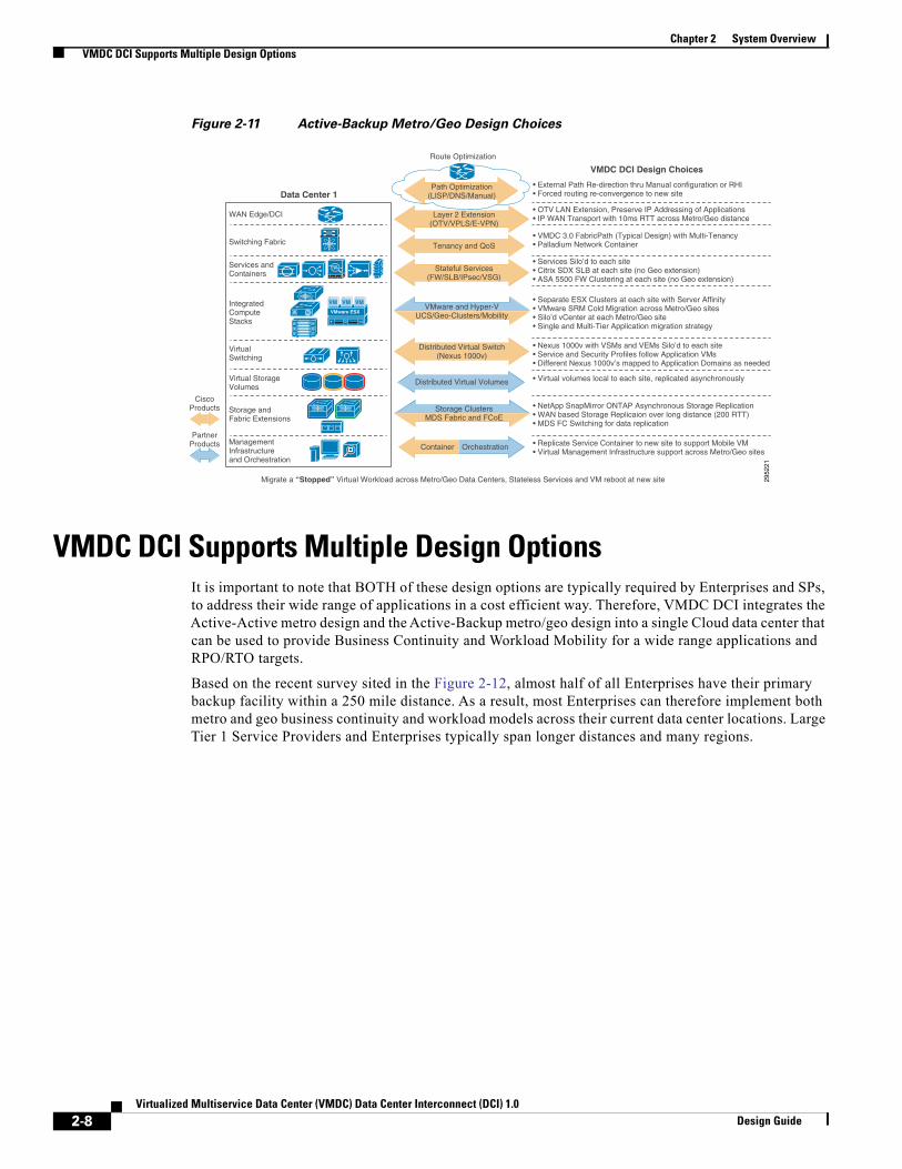
Active-Backup Metro/Geo DesignThe second model, Active-Backup metro/geo Design represents a more traditional primary/backup redundancy design, where two independent data centers provide recovery and workload mobility functions across both metro and geo distances, as described in Figure 2-9. This model can address less stringent RTO/RPO targets, where applications require Cold workload mobility/recovery in which applications and corresponding network services are restarted at the recovery location.
2-6Virtualized Multiservice Data Center (VMDC) Data Center Interconnect (DCI) 1.0
Design Guide

Chapter 2 System OverviewActive-Backup Metro/Geo Design
Figure 2-9 Active-Backup Metro/Geo Design
2952
19
Data Center 1
Services andContainers
IntegratedComputeStacks
VirtualSwitching
Virtual StorageVolumes
Storage andFabric Extensions
ManagementInfrastructureand Orchestration
ManagementInfrastructureand Orchestration
WAN Edge/DCI
Switching Fabric
VMware ESX
VM VM VM
Data Center 2
Services andContainers
IntegratedComputeStacks
VirtualSwitching
Virtual StorageVolumes
Storage andFabric Extensions
WAN Edge/DCI
Metro or Geo Connections
Switching Fabric
VMware ESX
VM VM VM
Asynchronous StorageReplicatioin
Cold Workload Mobilitywith Site Recovery Tools
These Sites are Operating as TWO Independent Data Centers
LAN Extensions
This Business Continuity and Workload Mobility design is best suited for moving or migrating “stopped workloads” between different Cloud data centers as described in Figure 2-10. These less stringent RPO/RTO requirements enable the participating data center to span a geo distance of more than 200 km. In this model, LAN extensions between data centers is optional, but may be necessary for operators that need to preserve to IP addressing for applications and services. In addition, Asynchronous data replication used to achieve less stringent RPO/RTO targets.
Figure 2-10 Migrating Stopped Workloads
2952
20
Hypervisor ControlTraffic (routable)
Moving workloads with optional LAN extensions
Moving Workloads
IP Network
Hypervisor Hypervisor
WestData Center
EastData Center
Asynchronous Data Replication
The key VMDC DCI design choices for the Active-Backup metro/geo design are described in Figure 2-11.
2-7Virtualized Multiservice Data Center (VMDC) Data Center Interconnect (DCI) 1.0
Design Guide
Chapter 2 System OverviewVMDC DCI Supports Multiple Design Options
Figure 2-11 Active-Backup Metro/Geo Design Choices
2952
21
Data Center 1
Services andContainers
IntegratedComputeStacks
VirtualSwitching
Virtual StorageVolumes
Storage andFabric Extensions
ManagementInfrastructureand Orchestration
WAN Edge/DCI
Switching Fabric
VMware ESX
VM VM VM
VMDC DCI Design Choices
• External Path Re-direction thru Manual configuration or RHI• Forced routing re-convergence to new site
• OTV LAN Extension, Preserve IP Addressing of Applications• IP WAN Transport with 10ms RTT across Metro/Geo distance
• VMDC 3.0 FabricPath (Typical Design) with Multi-Tenancy• Palladium Network Container
• Services Silo’d to each site• Citrix SDX SLB at each site (no Geo extension)• ASA 5500 FW Clustering at each site (no Geo extension)
• Separate ESX Clusters at each site with Server Affinity• VMware SRM Cold Migration across Metro/Geo sites• Silo’d vCenter at each Metro/Geo site• Single and Multi-Tier Application migration strategy
• Nexus 1000v with VSMs and VEMs Silo’d to each site• Service and Security Profiles follow Application VMs• Different Nexus 1000v’s mapped to Application Domains as needed
• Virtual volumes local to each site, replicated asynchronously
• NetApp SnapMirror ONTAP Asynchronous Storage Replication• WAN based Storage Replicaion over long distance (200 RTT)• MDS FC Switching for data replication
• Replicate Service Container to new site to support Mobile VM• Virtual Management Infrastructure support across Metro/Geo sites
Route Optimization
Migrate a “Stopped” Virtual Workload across Metro/Geo Data Centers, Stateless Services and VM reboot at new site
Path Optimization(LISP/DNS/Manual)
Layer 2 Extension(OTV/VPLS/E-VPN)
Stateful Services(FW/SLB/IPsec/VSG)
CiscoProducts
PartnerProducts
Distributed Virtual Switch(Nexus 1000v)
VMware and Hyper-VUCS/Geo-Clusters/Mobility
Storage ClustersMDS Fabric and FCoE
Tenancy and QoS
Distributed Virtual Volumes
OrchestrationContainer
VMDC DCI Supports Multiple Design OptionsIt is important to note that BOTH of these design options are typically required by Enterprises and SPs, to address their wide range of applications in a cost efficient way. Therefore, VMDC DCI integrates the Active-Active metro design and the Active-Backup metro/geo design into a single Cloud data center that can be used to provide Business Continuity and Workload Mobility for a wide range applications and RPO/RTO targets.
Based on the recent survey sited in the Figure 2-12, almost half of all Enterprises have their primary backup facility within a 250 mile distance. As a result, most Enterprises can therefore implement both metro and geo business continuity and workload models across their current data center locations. Large Tier 1 Service Providers and Enterprises typically span longer distances and many regions.
2-8Virtualized Multiservice Data Center (VMDC) Data Center Interconnect (DCI) 1.0
Design Guide

Chapter 2 System OverviewTop Level Use Cases
Figure 2-12 Typical Enterprise Geo-Redundancy1
2952
22
Greater than 1,000 miles
48% Less than 250 miles apart
27% Less than 50 miles apart
22%
“What is the distance between your primary centerand your furthest backup data center, in miles?”
Half of Enterprises can deployVMDC DCI Metro and Geo designs
across their current Data Center sites
May 2011 “State of Enterprise Disaster Recovery Preparedness, Q2 2011”
Base: disaster recovery decision-makers and influencers at enterprises globally with a recovery site(does not include those who answered “Don’t know”)
(percentages may not total 100 due to rounding)
Source: Forrester/Disaster Recovery Journal October 2007 Global Disaster Recovery Preparedness OnlineSurvey and Forrester/Disaster Recovery Journal November 2010 Global Disaster Recovery PreparednessOnline Survey
12%
15%24%
13%16%
5%9%
10%12%
15%11%
17%16%
20072010
500 to less than 1,000 miles
100 to less than 250 miles
250 miles to less than 500 miles
50 miles to less than 100 miles
25 miles to less than 50 miles
Less than 25 miles
Top Level Use CasesTop level use cases validated in VMDC DCI are mapped to one of the following design choices:
• Design Parameters for Active-Active Metro Use Cases, page 2-9
• Design Parameters for Active-Standby Metro/Geo Use Cases, page 2-10
Design Parameters for Active-Active Metro Use CasesVMDC DCI used the following design parameters in the Active-Active metro design.
Live Workload Mobility can Solve Specific Business Problems
• Perform live (or cold) workload migrations between metro data centers
• Perform operations re-balancing/maintenance/consolidation of live (or cold) workloads between metro data centers
• Provide disaster avoidance of live (or cold) workloads between metro data centers
• Implement application geo-clusters spanning metro DCs
• Utilized for the most business critical applications (lowest RPO/RTO)
• Maintain user connections for live workload moves
• Implement load balanced workloads between metro DC's
Hypervisor tools utilized to implement Live Workload Mobility
• VMware live vMotion
• Stretched HA/DRS clusters across metro data centers
• Single vCenter across metro data centers1. Source: Forrester “State of Enterprise Disaster Recovery Preparedness, May 2011
2-9Virtualized Multiservice Data Center (VMDC) Data Center Interconnect (DCI) 1.0
Design Guide

Chapter 2 System OverviewTop Level Use Cases
• DRS host Affinity rules to manage compute resources
Metro Data Center Infrastructure to support Live Workload Mobility
• Network—Data Center Interconnect extensions between metro data centers
– Simplified LAN extensions using Overlay Transport Virtualization (OTV) is used to preserve IP addressing of applications and support Live migrations
– Virtual switches distributed across metro data centers
– Tenant Containers spanning multiple sites
– Maintain traffic QoS and packet markings across metro networks
• Services—Maintain stateful services for active connections where possible
– Support a combination of services hosted physical appliances, as well as virtual services hosted on the UCS
– Minimize traffic tromboning between metro data centers
• Compute—Support single-tier and multi-tier applications
– Multiple UCS systems across metro DC's to support workload mobility
• Storage—Storage extended across metro, synchronous and asynchronous replication
– Distributed storage clusters spanning metro data centers
Figure 2-13 shows a typical live migration of an active workload. Each tier of data center is impacted by this use case.
Figure 2-13 Live Workload Mobility
2952
23Data Center 1
ServiceContainers
IntegratedComputeStacks
Continuous SynchronousStorage Replication
VirtualSwitching
Virtual StorageVolumes
Storage andFabric Extensions
ManagementInfrastructureand Orchestration
ManagementInfrastructureand Orchestration
WAN Edge/DCI
Core/Aggregation
VMware ESX
VM VM VM
Data Center 2
IntegratedComputeStacks
Virtual StorageVolumes
Storage andFabric Extensions
WAN Edge/DCI
VMware ESX
VM VM VMAPPOS
APPOS
1
Live VM Migration acrossLAN extensions, VitrualServices follow VM, IPAddressing preserved
Trombone to original sitefor active flows, use originalNetwork Container (andoriginal physical appliancesif needed) to maintainStateful Services
2
3
With ServiceOrchestration,Create a newNetwork Containerat DC-2
4
Orchestration redirects external flows to DC-2, connecting users to DC-2 network container and the moved application (LISP Future)
5
Migration of Live Workload complete!Compute, Network, Storage, and Services are now local to DC-2. Reclaim DC-1 resources for new workloads.
6
Live VM
Branch
Metro Network
Move a “Live” Workload across Metro Data Centers while maintaining Stateful Services
ServiceContainers
SynchronousStorage
Stateful Services
VirtualSwitching
Core/Aggregation
Design Parameters for Active-Standby Metro/Geo Use CasesVMDC DCI used the following design parameters in the Active-Standby metro/geo design.
2-10Virtualized Multiservice Data Center (VMDC) Data Center Interconnect (DCI) 1.0
Design Guide

Chapter 2 System OverviewTop Level Use Cases
Cold Workload Mobility can solve specific Business problems
• Perform planned workload migrations of stopped VMs between metro/geo data centers
• Operations rebalancing/maintenance/consolidation of stopped workloads between metro/geo data centers
• Disaster avoidance or recovery of stopped workloads
• User connections will be temporarily disrupted during the move process
• Site migrations across metro/geo data centers of stopped workloads
• Utilized for less business critical applications (Medium to High RPO/RTO)
Hypervisor tools utilized to implement Cold Workload Mobility
• VMware Site Recovery Manager (SRM) and VMware High Availability
• Resource pools mapped to Active/Active or Active/Standby metro/geo DCs
• Host Affinity rules to manage compute resources
• Many-to-One Site Recovery Scenarios
Metro/Geo Data Center Infrastructure to support Cold Workload Mobility
• Network—Data Center Interconnect is optional
– Simplified LAN extensions using Overlay Transport Virtualization (OTV) is used to preserve IP addressing of applications
– Multiple UCS systems utilized to house moved workloads at the recovery site
– Create new tenant containers at recovery site to support the moved workloads
• Services—Service connections will be temporarily disrupted
– New network containers and services created at new site
– Traffic tromboning between metro DCs can be avoided in many cases
• Compute—Support Single-Tier and Multi-Tier Applications
• Storage—Asynchronous Data Replication to remote site
– Virtual Volumes silo’d to each DC
Figure 2-14 shows the different infrastructure components involved in the cold migration of a stopped workload. Each tier of data center is impacted by this use case.
2-11Virtualized Multiservice Data Center (VMDC) Data Center Interconnect (DCI) 1.0
Design Guide

Chapter 2 System OverviewSolution Architecture
Figure 2-14 Components of Stopped Workload Cold Migration
2952
24
Data Center 1
ServiceContainers
IntegratedComputeStacks
Continuous AsynchronousStorage Replication
VirtualSwitching
Virtual StorageVolumes
Storage andFabric Extensions
ManagementInfrastructureand Orchestration
ManagementInfrastructureand Orchestration
WAN Edge/DCI
Core/Aggregation
VMware ESX
VM VM VM
Data Center 2
IntegratedComputeStacks
Virtual StorageVolumes
Storage andFabric Extensions
WAN Edge/DCI
VMware ESX
VM VM VMAPPOS
APPOS
1
VM is halted. SRM based Cold Migration of stopped VM across IP WAN, Virtual Services follow VM, IP Addressing preserved
Trombone to original site if maintaining original Network Container (and original physical appliances).This step is optional.
2
3a
Reboot Moved VMat new site
5
With ServiceOrchestration,Create a newNetwork Containerat DC-2
3
Orchestration redirects external flows to DC-2, connecting users to DC-2 network container and the moved application (LISP Future)
4
Migration of Cold Workload complete!Compute, Network, Storage, and Services are now local to DC-2. Reclaim DC-1 resources for new workloads.
6
Stopped VM
Branch
Metro/Geo Network
Move a “Stopped” Workload across Metro Data or Geo Centers
ServiceContainers
AsynchronousStorage
Stateful Services
VirtualSwitching
Core/Aggregation
Solution ArchitectureTop lever use components validated in VMDC DCI are mapped to one of the following design choices:
• Active-Active Metro Design, page 2-12
• Active-Backup Metro/Geo Design, page 2-13
Active-Active Metro DesignThe Active-Active metro design used in the VMDC DCI system is included in Figure 2-15. The physical sites are separated by a metro distance of 75 Km. Layer 2 LAN extensions are included to support multi-site hypervisor clusters, stretched network containers, and preservation of IP addressing for workloads. Storage is extended between sites to support active-active clusters and synchronous storage replication. Asynchronous storage replication between sites is also provided for less business critical applications.
2-12Virtualized Multiservice Data Center (VMDC) Data Center Interconnect (DCI) 1.0
Design Guide

Chapter 2 System OverviewSolution Architecture
Figure 2-15 Active-Active Metro DesignTopology
Active-Backup Metro/Geo DesignThe Active-Backup metro/geo Design validated in the VMDC DCI system is included in Figure 2-16. The physical sites are separated by a geo Distance of 1000 Km. Layer 2 LAN extensions are optional. Storage is contained to each site. Asynchronous storage replication provides long distance data replication between sites.
2-13Virtualized Multiservice Data Center (VMDC) Data Center Interconnect (DCI) 1.0
Design Guide

Chapter 2 System OverviewSystem Components
Figure 2-16 Active-Backup Metro/Geo DesignTopology
System ComponentsTable 2-1 and Table 2-2 list product components for Cisco and Partners, respectively.
Table 2-1 Cisco Components
Role Cisco Products
WAN Edge / Core ASR-1004 Nexus 7010
Aggregation FabricPath Spine
Nexus 7009
Access-Edge FabricPath Leaf
Nexus 6004 Nexus 5548 Nexus 7004 w Sup2/F2
FEX N2K-C2232PP/N2K-C2248TP-E
Fabric Interconnect UCS 6248UP
Compute UCS B-200-M3s /M2 UCS M81KR Virtual Interface card UCS P81E Virtual Interface card UCS Virtual Interface card 1280, 1240
Virtual Access Switch Nexus 1000v
Virtual Firewall VSG
2-14Virtualized Multiservice Data Center (VMDC) Data Center Interconnect (DCI) 1.0
Design Guide

Chapter 2 System OverviewSystem Components
Physical Firewall ASA5585X
Storage Fabric MDS9148
Table 2-2 Third Party and Partner Products
Role Partner Products
SAN/NAS Storage NetApp MetroCluster NetApp SnapMirror FAS 6080/6040 FAS 3250
Hypervisor VMWare vSphere 5.1 Site Recovery Manager 5.1
Server Load Balancers NetScaler SDX
Applications used to demonstrate Migration use cases Microsoft SharePoint & Visual Studio Oracle & Swingbench
Table 2-1 Cisco Components (continued)
Role Cisco Products
2-15Virtualized Multiservice Data Center (VMDC) Data Center Interconnect (DCI) 1.0
Design Guide

Chapter 2 System OverviewSystem Components
2-16Virtualized Multiservice Data Center (VMDC) Data Center Interconnect (DCI) 1.0
Design Guide
Virtualized Multiservice Data CDesign Guide
C H A P T E R 3
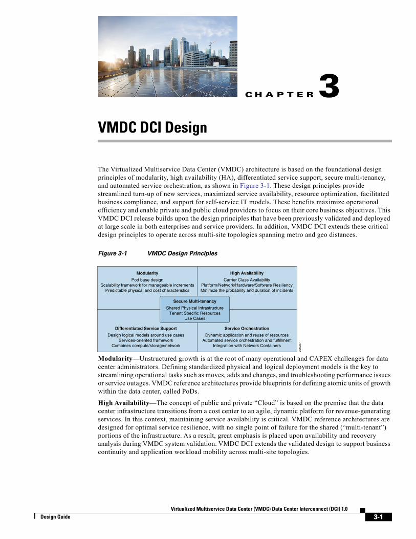
VMDC DCI DesignThe Virtualized Multiservice Data Center (VMDC) architecture is based on the foundational design principles of modularity, high availability (HA), differentiated service support, secure multi-tenancy, and automated service orchestration, as shown in Figure 3-1. These design principles provide streamlined turn-up of new services, maximized service availability, resource optimization, facilitated business compliance, and support for self-service IT models. These benefits maximize operational efficiency and enable private and public cloud providers to focus on their core business objectives. This VMDC DCI release builds upon the design principles that have been previously validated and deployed at large scale in both enterprises and service providers. In addition, VMDC DCI extends these critical design principles to operate across multi-site topologies spanning metro and geo distances.
Figure 3-1 VMDC Design Principles
2952
27
Modularity
Pod base designScalability framework for manageable increments
Predictable physical and cost characteristics
High Availability
Carrier Class AvailabilityPlatform/Network/Hardware/Software ResiliencyMinimize the probability and duration of incidents
Differentiated Service Support
Design logical models around use casesServices-oriented framework
Combines compute/storage/network
Service Orchestration
Dynamic application and reuse of resourcesAutomated service orchestration and fulfillment
Integration with Network Containers
Secure Multi-tenancy
Shared Physical InfrastructureTenant Specific Resources
Use Cases
Modularity—Unstructured growth is at the root of many operational and CAPEX challenges for data center administrators. Defining standardized physical and logical deployment models is the key to streamlining operational tasks such as moves, adds and changes, and troubleshooting performance issues or service outages. VMDC reference architectures provide blueprints for defining atomic units of growth within the data center, called PoDs.
High Availability—The concept of public and private “Cloud” is based on the premise that the data center infrastructure transitions from a cost center to an agile, dynamic platform for revenue-generating services. In this context, maintaining service availability is critical. VMDC reference architectures are designed for optimal service resilience, with no single point of failure for the shared (“multi-tenant”) portions of the infrastructure. As a result, great emphasis is placed upon availability and recovery analysis during VMDC system validation. VMDC DCI extends the validated design to support business continuity and application workload mobility across multi-site topologies.
3-1enter (VMDC) Data Center Interconnect (DCI) 1.0

Chapter 3 VMDC DCI Design
Differentiated Service—Generally, bandwidth is plentiful in the data center infrastructure. However, clients may need to remotely access their applications via the Internet or some other type of public or private WAN. Typically, WANs are bandwidth bottlenecks. VMDC provides an end-to-end QoS framework for service tuning based upon application requirements. VMDC DCI extends this end-to-end QoS framework across multi-site topologies.
Multi-tenancy—As data centers transition to Cloud models, and from cost centers to profit center, services will naturally broaden in scope, stretching beyond physical boundaries in new ways. Security models must also expand to address vulnerabilities associated with increased virtualization. In VMDC, “multi-tenancy” is implemented using logical containers, also called “Cloud Consumer” that are defined in these new, highly virtualized and shared infrastructures. These containers provide security zoning in accordance with Payment Card Industry (PCI), Federal Information Security Management Act (FISMA), and other business and industry standards and regulations. VMDC is certified for PCI and FISMA compliance. VMDC DCI extends multi-tenancy and security constructs across multi-site environments.
Service Orchestration—Industry pundits note that the difference between a virtualized data center and a “cloud” data center is the operational model. The benefits of the cloud – agility, flexibility, rapid service deployment, and streamlined operations – are achievable only with advanced automation and service monitoring capabilities. The VMDC reference architectures include service orchestration and monitoring systems in the overall system solution. This includes best-of-breed solutions from Cisco (for example, Cisco Intelligent Automation for Cloud) and partners, such as BMC and Zenoss.
The following sections provide design guidance to extend each element of application environment across multi-site topologies. As shown in Figure 3-2, the extended application environment includes:
• WAN Connectivity and Multi-site LAN Extensions
• Data Center Fabric Networking to implement tenancy, network containers, and QoS
• L4-L7 Services to implement physical/virtual services including security and load balancing
• Hypervisors and Virtual Networking to implement workload migrations and virtual switching
• Compute resources spanning multiple sites
• Storage resources to implement multi-site clusters and data replication
Figure 3-2 DCI Extensions Across the Application Environment
2955
31
THE COMPLETE APPLICATION ENVIRONMENT IS EXTENDED TO SUPPORT MULTI-SITE TOPOLOGIES
DC FabricNetworking
L4–L7Services
Multi DCWAN and Cloud
Compute StorageHypervisorsand VirtualNetworking
Site 1 Site 2
WAN ConnectivityL3 Routing and IGPData Center Interconnect
Tenancy Network Containers Traffic QoSBandwidth Reservation
Physical L4-L7 ServicesVirtual L4-L7 ServicesService Chaining
Workload MigrationsExtended ClustersHigh Availability Virtual Switching
Unified Compute System Port and Security ProfilesIntegrated PoDs
Storage NAS/SANVirtual VolumesStorage FabricsData Replication
VMDC DCI Extensions
3-2Virtualized Multiservice Data Center (VMDC) Data Center Interconnect (DCI) 1.0
Design Guide

Chapter 3 VMDC DCI DesignData Center Fabric Design
Data Center Fabric DesignVMDC DCI leverages FabricPath as the Unified Data Center fabric. FabricPath combines the stability and scalability of routing in Layer 2 (L2), supporting the creation of simple, scalable, and efficient L2 domains that apply to many network scenarios. Because traffic forwarding leverages the Intermediate System to Intermediate System (IS-IS) protocol, rather than Spanning Tree (STP), the bisectional bandwidth of the network is expanded, facilitating data center-wide workload mobility.
Preview a brief primer on FabricPath technology for details.
FabricPath benefits include:
Simplified Network, Reducing Operating Expenses
• FabricPath is simple to configure. The only necessary configuration consists of distinguishing core ports, which link the switches, from edge ports, to which end devices are attached. No parameters need to be tuned to achieve operational status, and switch addresses are assigned automatically.
• One control protocol is used for unicast forwarding, multicast forwarding, and VLAN pruning. Networks designed using FabricPath require less combined configuration than equivalent networks based on STP, further reducing the overall management needed for the solution.
• Static network designs make assumptions about traffic patterns and the locations of servers and services. If, as often happens over time, those assumptions become incorrect, complex redesign can be necessary. A fabric switching system based on FabricPath can be easily expanded as needed with additional access nodes in a plug and play manner, with minimal operational impact.
• Switches that do not support FabricPath can still be attached to the FabricPath fabric in a redundant way without resorting to STP.
• FabricPath L2 troubleshooting tools provide parity with those currently available in the IP community for non-fabric path environments. For example, the Ping and Traceroute features now offered at L2 with FabricPath can measure latency and test a particular paths among the multiple equal-cost paths to a destination within the fabric.
Reliability Based on Proven Technology
• Although FabricPath offers a plug-and-play user interface, its control protocol is built on top of the powerful IS-IS routing protocol, an industry standard that provides fast convergence and is proven to scale in the largest service provider (SP) environments.
• Loop prevention and mitigation is available in the data plane, helping ensure safe forwarding unmatched by any transparent bridging technology. FabricPath frames include a time-to-live (TTL) field similar to the one used in IP, and an applied reverse-path forwarding (RPF) check.
Efficiency and High Performance
• With FabricPath, equal-cost multipath (ECMP) protocols used in the data plane can enable the network to find optimal paths among all the available links between any two devices. First-generation hardware supporting FabricPath can perform 16-way ECMP, which, when combined with 16-port 10 gigabits per second (Gbps) port-channels, represents bandwidth of up to 2.56 terabits per second (Tbps) between switches.
• With FabricPath, frames are forwarded along the shortest path to their destination, reducing the latency of the exchanges between end stations compared to a STP based solution.
• FabricPath needs to learn at the edge of the fabric only a subset of the MAC addresses present in the network, enabling massive scalability of the switched domain.
3-3Virtualized Multiservice Data Center (VMDC) Data Center Interconnect (DCI) 1.0
Design Guide

Chapter 3 VMDC DCI DesignData Center Fabric Design
FabricPath TerminologyFabricPath comprises two types of nodes: spine nodes and leaf nodes. A spine node is one that connects to other switches in the fabric and a leaf node is one that connects to servers. These terms are useful in greenfield scenarios but may be vague for migration situations, where one has built a hierarchical topology and is accustomed to using traditional terminology to describe functional roles.
In this document, we expand our set of terms to correlate fabric path nodes and functional roles to hierarchical network terminology:
• Aggregation-Edge—A FabricPath node that sits at the “edge” of the fabric, corresponding to an aggregation node in a hierarchical topology.
• Access-Edge—A FabricPath node that sits at the edge of the fabric, corresponding to an access node in a hierarchical topology.
These nodes may perform L2 and/or L3 functions. At times, we also refer to an L3 spine or a L3 edge node to clarify the location of Layer 2/Layer 3 boundaries and distinguish between nodes that are performing Layer 3 functions versus L2-only functions.
FabricPath TopologiesFabricPath can be implemented in a variety of network designs, from full-mesh to ring topologies. In VMDC 3.0.X design and validation, the following DC design options, based on FabricPath, were considered:
• Typical Data Center Design—This model represents a starting point for FabricPath migration, where FabricPath is simply replaces older layer 2 resilience and loop avoidance technologies, such as virtual port channel (vPC) and STP. This design assumes that the existing hierarchical topology, featuring pairs of core, aggregation, and access switching nodes, remains in place and that FabricPath provides L2 multipathing.
• Switched Fabric Data Center Design—This model represents horizontal infrastructure expansion of the infrastructure to leverage improved resilience and bandwidth, characterized by a Clos architectural model.
• Extended Switched Fabric Data Center Design—This model assumes further expansion of the data center infrastructure fabric for inter-PoD or inter-building communication.
These are discussed in detail in VMDC 3.0 documentation: The Design Guide is publicly available, while the Implementation Guide is available to partners, and to Cisco customers under NDA.
While the logical containers discussed in VMDC DCI may be implemented over a traditional classical Ethernet (vPC) or FabricPath designs, this release is based on the Typical Data Center FabricPath design option previously validated in VMDC 3.0/3.0.1.
FabricPath “Typical Data Center” ModelA Typical Data Center design is a two-tier FabricPath design as shown in Figure 3-3. VMDC architectures are built around modular building blocks called PoDs. Each PoD uses a localized Services attachment model. In a classical Ethernet PoD, vPCs handle L2 switching, providing an active-active environment that does not depend on STP, but converges quickly after failures occur. In contrast, Figure 3-3 shows a VMDC PoD with FabricPath as a vPC replacement.
3-4Virtualized Multiservice Data Center (VMDC) Data Center Interconnect (DCI) 1.0
Design Guide

Chapter 3 VMDC DCI DesignLayer 3 Design
Figure 3-3 Typical Data Center Design
• From a resilience perspective, a vPC-based design is sufficient at this scale, although there are other benefits of using FabricPath, including:
• FabricPath is simple to configure and manage. There is no need to identify a pair of peers or configure port channels. Nevertheless, port channels can still be leveraged in FabricPath topologies if needed.
• FabricPath is flexible. It does not require a particular topology, and functions even if the network is cabled for the classic triangle vPC topology. FabricPath can accommodate any future design.
• FabricPath does not use or extend STP. Even a partial introduction of FabricPath benefits the network because it segments the span of STP.
• FabricPath can be extended easily without degrading operations. Adding a switch or a link in a FabricPath-based fabric does not result in lost frames. Therefore, it is possible to start with a small network and extend it gradually, as needed.
• FabricPath increases the pool of servers that are candidates for VM mobility and thereby enables more efficient server utilization.
Note Certain application environments, especially those that generate high levels of broadcast, may not tolerate extremely large Layer 2 environments.
Layer 3 DesignVMDC DCI will follow the design of VMDC 3.0/3.0.1 and will use a combination of dynamic and static routing to communicate reachability information across the layer three portions of the infrastructure. In this design dynamic routing is achieved using OSPF as the IGP. The Core routers are OSPF Area Border Routers (ABR) connecting to OSPF Area 0 in the IP Core and the NSSA area within the data center. To scale IP prefix tables, aggregation-edge nodes are placed in stub areas with the aggregation-edge node advertising “default route” (Type 7) for reachability. Service appliances (ASA Firewall and Citrix SDX SLB) are physically connected directly to the aggregation-edge nodes; reachability to/from these appliances is communicated via static routes. In the case of clustered ASA firewalls, for traffic from the
3-5Virtualized Multiservice Data Center (VMDC) Data Center Interconnect (DCI) 1.0
Design Guide

Chapter 3 VMDC DCI DesignServices
ASA(s) to the Nexus 7000 aggregation-edge nodes, a default static route points to the HSRP VIP on the Nexus 7000, while for traffic from the Nexus 7000 aggregation-edge to the ASA, a static route on the Nexus 7000 for server subnets points to the ASA outside IP interface address.
Since VMDC DCI will use the “Typical Data Center” design, the Citrix SDX SLB appliance is configured in one-arm mode. This has several key benefits, especially in multi-site scenarios:
• One-arm mode limits the extension of FabricPath VLANs to the appliances
• One-arm mode keeps VLAN ARP entries off the SDX SLB
• The port-channel attachment method allows for a separation of failure domains.
• Source-NAT on the SDX SLB insures symmetric routing and a return path for moved workloads. This is especially important for DCI designs that span multiple sites.
VRF-lite is implemented on the aggregation-edge nodes and provides a unique per-tenant VRF. This design secures and isolates private tenant applications and zones via dedicated routing and forwarding tables. Figure 3-4 shows the Layer 3 implementation for the Typical Data Center design and describes connections for a single tenant.
Figure 3-4 Layer 3 Connectivity Design
VMDC DCI uses the Typical Data Center design featuring a two-node Layer 3 spine (aka aggregation-edge nodes). In this model, active/active gateway routing is enabled through the use of vPC+ on the inter-Spine (FabricPath) peer-link. This creates a single emulated switch from both spine nodes. HSRP thus announces the virtual MAC of the emulated switch ID, enabling dual-active paths from each access-edge switch device, serving to optimize resiliency and throughput, while providing for efficient East/West routing.
ServicesDesign considerations for the services components within the Cloud data center infrastructure are described below.
3-6Virtualized Multiservice Data Center (VMDC) Data Center Interconnect (DCI) 1.0
Design Guide

Chapter 3 VMDC DCI DesignServices
The Citrix NetScaler Software Load Balancer (SLB) and ASA 5585 firewall appliances are used in a Typical DC design to provide load balancing and front-end/first-tier firewalling. The VMDC DCI architecture utilizes clustered ASA Firewalls (Release 9.0+). This feature serves two functions: enhanced resiliency and capacity/throughput expansion. Up to eight Cisco ASA 5585-X or 5580 Adaptive Security Appliance firewall modules may be joined in a single cluster to deliver up to 128 Gbps of multiproduct throughput (300 Gbps maximum) and more than 50 million concurrent connections. This is achieved via the Cisco Cluster Link Aggregation Control Protocol (cLACP), which enables multi-system ASA clusters to function and be managed as a single entity. This provides significant benefits in terms of streamlined operation and management, in that firewall policies pushed to the cluster get replicated across all units within the cluster, while the health, performance and capacity statistics of the entire cluster may be managed from a single console.
Clustered ASA appliances can operate in routed, transparent, or mixed-mode. However, all members of the cluster must be in the same mode. Clustered ASA appliances in this system release will be deployed and validated in routed mode.
It is important to note that transparent mode deployment considerations are discussed in the VMDC white paper.
Characteristics of the appliance-based service attachment as implemented in the Typical DC model include:
• VMDC DCI uses a vPC attachment from clustered ASAs to Nexus 7000 aggregation-edge nodes to provide enhanced resiliency. More specifically, one vPC (across 2 clustered ASAs) to the N7k aggregation-edge nodes is utilized for data traffic, and multiple port-channels per ASA (to vPCs on the Nexus 7000 aggregation-edge nodes) are used for communication of cluster control link (CCL) traffic. Similarly, the Citrix SDX SLBs uses vPCs connections per SDX appliance to both redundant aggregation-edge nodes to provide SLB resiliency.
• The Citrix SDX SLB is in “one-arm” mode to optimize traffic flows for load balanced and non-load balanced traffic. This limits the extension of FabricPath VLANs to the appliances, and keeps the VLAN ARP entries off the SDX. Source-NAT on the SDX SLB insures symmetric routing and a return path for moved workloads extended across the multiple sites
• Active/Active Failover between redundant (non-clustered) appliances through configuration of active/standby pairs on alternating (primary/secondary) contexts. In contrast, the clustered resilience functionality available on the ASA is such that every member of the cluster is capable of forwarding every traffic flow and can be active for all flows. All resiliency implementations will be contained within a single data center since neither Cisco ASA firewalls or Citrix SLB currently support clustering over a metro distance at this time.
• VMDC DCI follows current best-practice recommendations, using out-of-band links for FT state communication between redundant appliances. In the context of non-clustered, redundant ASA pairs, interface monitoring is activated to insure proper triggering of failover to a standby interface, only one interface (inside or outside) must be monitored per FT failover group, though monitoring of both is possible. Should it feature higher resilience characteristics, the management path between the redundant ASAs could be a monitoring option. For clustered ASA appliances, the CCL (Cluster Control Link) communicates control plane information between cluster members, including flow re-direction controls. This design follows best practice recommendations for CCL high availability by employing vPCs on the redundant N7k aggregation-edge from port-channels on each ASA in the cluster.
The appliances are statically routed, and redistributed into NSSA area 10. Key considerations for this service implementation include:
3-7Virtualized Multiservice Data Center (VMDC) Data Center Interconnect (DCI) 1.0
Design Guide

Chapter 3 VMDC DCI DesignTenancy Models
• Disaster Recovery Implications—Disaster recovery must provide a complete replication of the network services resources and associated subnets at the recovery location for failover. Service orchestration will aid in the creation of recovery resources including L4-L7 services, network containers, and resource allocations across a range of application elements.
• Resource allocation for compute, storage and network services applied to multi-tiered applications is less complex, in that it is pod-based. This should translate to simpler workflow and resource allocation algorithms for service automation systems.
• Pod-based deployments represent a simple, clear-cut operational domain, for greater ease of troubleshooting and determination of dependencies in root-cause analysis.
Tenancy ModelsA primary focus of VMDC DCI is to determine the impact of workload migrations on VMDC network containers and related L4-L7 services. Certain workload moves (Live Migrations) require that existing network connections remain intact, and that existing services remain stateful throughout the move. This will typically require some type of temporary “tromboning” back to the original data center for existing connections and related services. Other workload moves (Cold Migration) allow workloads and existing network connections to be terminated and restarted at a new location. In both cases, new network containers will be created at the recovery site, and external users will be redirected to the new site where workload has been moved.
From an architectural perspective, VMDC DCI remains aligned with tenancy models previously defined in VMDC 2.3 and VMDC 3.0/3.0.1 releases. A number of VMDC containers are presented in Figure 3-5.
Figure 3-5 VMDC Network Containers
Bronze Silver Gold Palladium
VMVM VM VMVM VM VMVM VM VMVM VM
vFW vFW vFW
L3
Public Zone
Public Zone
Private Zone
L3
L2
L3
L3
L2
L3
FW
LB LB
LB
LB
L3
L2
L3
FW
L2
VM VM
Expanded Gold
VMVM VM
vFW
vFW
ProtectedFront-End
ProtectedBack-End
LB
LB
L3
FW
FW
L2
VM VM
Expanded Palladium Multi-zone
VSGVM VM
VMVM VM
VSG
PrivateZone 1
PrivateZone 32
LB
L3
FW
L2
2952
30
VMVM VM
VSG
LB
L3
FW
L2
LB
Modifications to network containers for VMDC DCI include:
• The introduction of Citrix SDX load balancer appliances to replace Cisco ACE load balancers across each container
• The validation of Clustered ASA Firewall appliances within the Expanded Palladium Multi-zone container
• Validate network container performance across multi-site scenarios in which the application and services may reside at different locations
• Validate the migration strategy used to move complete tenants and related containers to a new site.
3-8Virtualized Multiservice Data Center (VMDC) Data Center Interconnect (DCI) 1.0
Design Guide

Chapter 3 VMDC DCI DesignLAN Extension Options for Multi-Site Topologies
A primary focus of the VMDC DCI is to determine the impact of workload mobility on different network containers and their related L4-L7 services. The Expanded Palladium container was validated in the release and is typically implemented for Enterprise Private Clouds.
Expanded Palladium Multi-zone—The Expanded Palladium Multi-zone container implements separate front-end and back-end security zones, each of which may have a different set of network services applied. The original Palladium container aligns more closely with traditional zoning models in use in physical IT deployments. Private Cloud data centers employ an Expanded version of the Palladium container as described in Figure 3-6. The Expanded Palladium Multi-zone container supports additional capacity and many private zones, as described below.
• A single, shared (multi-tenant) public zone, with multiple server VLANs and a single Citrix SDX context (or multiple contexts) for SLB. This is in the global routing table used by the Public Zone.
• Multiple, private (unique per-tenant or user group) firewalled zones reachable via the public zone – i.e., the firewall “outside” interface is in the public zone. These private zones include a Citrix SDX SLB, and may have 1 to many VLANs.
• VSG vPath security can be applied in a multi-tenant/shared fashion to the public zone.
• VSG vPath security can be applied in dedicated fashion to each of the private zones, providing a second tier of policy enforcement, and back-end (East/West) zoning. Unique VLANs may be used per zone for VLAN-based isolation. However, in validation we assumed the desire to conserve VLANs would drive one to use a single VLAN with multiple security zones applied for policy-based isolation.
An alternative way to view this model is as a single, DC-wide “tenant” with a single front-end zone and multiple back-end zones for (East/West) application-based isolation.
Figure 3-6 Expanded Palladium Multi-Zone Container
LAN Extension Options for Multi-Site TopologiesThere are number of options available to implement Layer 2 Extensions for Data Center Interconnections. The specific choice of which DCI option best suits an SP or Enterprise is dependent on a number of factors including: the number of interconnected sites, number of VLAN/MACs extended, distance between sites, link type and available link bandwidth, operational complexity, L2 domain isolation, tenancy, and the cost of network interconnect links that support DCI traffic. Most of the current DCI choices fit into three categories listed in Figure 3-7.
3-9Virtualized Multiservice Data Center (VMDC) Data Center Interconnect (DCI) 1.0
Design Guide

Chapter 3 VMDC DCI DesignLAN Extension Options for Multi-Site Topologies
Figure 3-7 LAN Extension Options
The first DCI option includes Ethernet switching extensions over dark fiber and use either VSS, vPC, or FabricPath. These models are typically implemented in a dual site model and or may be contained to a campus distance. The second category includes a number of MPLS variants, including EoMPLS (VMDC previously validated), VPLS, and E-VPN (routed VPLS, future availability). These MPLS options are typically well suited for large SP or Enterprise customers with an MPLS backbone, many sites, and large multi-tenant cloud environments. The third option includes extensions supported over any IP transport such as OTV. OTV is well suited for Enterprise or SP style deployments with fewer sites and lower scaled tenants and VLANs. One final option includes Hypervisor based Overlays that could be used as DCI options, including VXLAN, NV-GRE, or STT. Most of these models are at various stages of development and have significant limitations that limit full scale deployments by large SPs or Enterprises in the near term. Most virtual overlay options in their current state are better suited for intra (within) site switching rather than inter (between) site DCI extensions.
The current Cisco positioning of relevant DCI technologies to handle Intra-Site versus Inter-Site connectivity is summarized in the Figure 3-8.
Figure 3-8 Intra-Site versus Inter-Site Connectivity
Based a number of new capabilities included in the Nexus 6.2 release, VMDC DCI validated OTV as the LAN extension option to support Private or Public Cloud deployments. Future VMDC releases will target VPLS or E-VPN DCI options to support larger Public Cloud deployments. OTV is a feature that allows Ethernet traffic from a local area network (LAN) to be tunneled over an IP network to create a “logical data center” spanning several data centers in different locations. OTV is well suited for Private Cloud Enterprise and SP customers.
OTV differentiated characteristics include:
3-10Virtualized Multiservice Data Center (VMDC) Data Center Interconnect (DCI) 1.0
Design Guide

Chapter 3 VMDC DCI DesignOTV Design Considerations
• Capability of extending Layer 2 LANs over any network by leveraging IP-encapsulated MAC routing.
• Simplification of configuration and operation by enabling seamless deployment over existing network without redesign, requiring minimal configuration commands and providing single-touch site configuration for adding new data centers.
• Increasing resiliency by preserving existing Layer 3 failure boundaries, providing automated multi-homing, and including built-in loop prevention.
• Maximizing available bandwidth by using equal-cost multipath and optimal multicast replication (in deployments where the transport infrastructure is multicast enabled).
The VMDC DCI design interconnects FabricPath data centers with OTV LAN extensions to emulate a three site data center business continuity design and enable various workload mobility options (Figure 3-9). Future VMDC releases will validate VPLS or E-VPN LAN extensions integrated with vPC or FabricPath designs to support larger Public Cloud business models.
Figure 3-9 FabricPath and OTVTopology
OTV Design ConsiderationsThe OTV implementation utilizes a dedicated Virtual Device Context (VDC) deployed at the aggregation layer of the VMDC DCI design. A dedicated OTV VDC will perform OTV functions while the Aggregation-VDC will provide SVI routing functions. The L2-L3 boundary is implemented on the Nexus 7000 aggregation device, as described in Figure 3-10. The Data Center core device (ASR 9K, ASR1K, or Nexus 7K) will only perform L3 functions. Spanning tree and L2 Broadcast domains will be isolated between data centers. OTV provides LAN extensions across geographic sites to connect distributed compute PoDs. OTV may also provide Intra-DC campus extensions if FabricPath is not sufficient.
3-11Virtualized Multiservice Data Center (VMDC) Data Center Interconnect (DCI) 1.0
Design Guide

Chapter 3 VMDC DCI DesignOTV Design Considerations
Figure 3-10 OTV Edge Device in the Aggregation Layer
There are multiple ways to attach OTV VDCs to aggregation layer devices, each with varied levels of resiliency. VMDC DCI used the dual-homed VDC attachment design described in Figure 3-11. This attachment design provides the best resiliency, although it does consume more physical interfaces than the less resilient single-homed option. As described in Figure 3-11, logical port-channels are used for the Join interfaces and the Internal interfaces. Therefore, traffic recovery after single link failure event is based on port-channel re-hashing. There is no need for Authoritative Edge Device (AED) re-election. In the event of a physical node (or VDC) failure, AED re-election is required, but collateral impact is limited to a few seconds and only for 50% of the extended VLANs.
Figure 3-11 Dual Homed OTV VDC
Similarly, there are different options to load balance VLANs across dual-homed aggregation devices. VMDC DCI implements the most resilient model, site based VLAN load balancing, described in the Figure 3-12. In this model, the AED role is negotiated between the two OTV VDCs (on a per VLAN basis). For a given VLAN all traffic must be carried to the AED Device. Traffic flows are optimized by
3-12Virtualized Multiservice Data Center (VMDC) Data Center Interconnect (DCI) 1.0
Design Guide

Chapter 3 VMDC DCI DesignOTV Design Considerations
leveraging resilient Port-Channels as Internal Interfaces. The AED encapsulates the original L2 frame into an IP packet and sends it back to the aggregation layer device. The aggregation layer device routes the IP packet toward the DC Core/WAN edge. L3 routed traffic bypasses the OTV VDC.
Figure 3-12 Per-VLAN Load Balancing
This release will validate OTV implementation over a multicast transport. The multicast topology example is provided in Figure 3-13. Unicast transport is also a supported option but was not implemented in this VMDC DCI release. MAC advertisements between OTV connected sites take on the following characteristics:
• MAC addresses are advertised with their VLAN IDs, IP next hop and Site-ID
• IP next hops are the addresses of Edge Devices’ Join interfaces
• Each OTV update can contain multiple MAC addresses for different VLANs
• When the MAC address ages out from the OTV Device MAC Table, an update is created and sent to the remote OTV Edge Devices (MAC Withdraw)
Figure 3-13 OTV MulticastTransportTopology
3-13Virtualized Multiservice Data Center (VMDC) Data Center Interconnect (DCI) 1.0
Design Guide

Chapter 3 VMDC DCI DesignOTV Design Considerations
VMDC DCI utilizes FHRP Filtering to insure that egress traffic flows are routed to an HSRP group that is local to each data center. This model is described in Figure 3-14. FHRP localization is achieved via a combination of VACLs and MAC route filters. The result is that different data centers can have the one HSRP group with one VIP, but each site has an active router used for first hop routing that is local to the site.
Figure 3-14 FHRP Filtering between Sites
There are a number of Nexus 7000 hardware limitations for the OTV implementation. These limitations are listed below and in Figure 3-15.
• OTV VDC must use only M-series ports for both internal and join interfaces
– Recommendation is to allocate M only interfaces to the OTV VDC
– All M series modules are supported (M1-48, M1-32, M1-08, M2 series)
• F1 and F2 linecards do not support OTV natively
– F1 and F2e support for OTV internal Interfaces is supported
Figure 3-15 NEXUS 7000 OTV Configuration
3-14Virtualized Multiservice Data Center (VMDC) Data Center Interconnect (DCI) 1.0
Design Guide

Chapter 3 VMDC DCI DesignNexus 1000v Virtual Switch Metro Extensions
As Enterprises and SPs extend their data centers for Business Continuity or Workload Mobility, it is likely that there will be overlapping VLANs allocations across data centers. Therefore, this release will implement a VLAN translation mechanism to overcome this issue, as described in Figure 3-16. This function will translate a local VLAN to remote VLAN in a different site (VLAN in the West Site corresponds to a different VLAN in the East Site).
Figure 3-16 OTV VLANTranslation between Sites
2952
41
DCWest
DCEast
OTV
OTV
OTV OTV
OTV
VLAN 100
VLAN 200
Nexus 1000v Virtual Switch Metro ExtensionsThe Cisco Nexus 1000V Series Switches are virtual machine access switches running the Cisco NX-OS operating system and supporting various hypervisors such as VMware vSphere and Microsoft Hyper-V. Operating inside the hypervisors, the Cisco Nexus 1000V Series provides Policy-based virtual machine connectivity, Mobile virtual machine security and network policy, and non-disruptive operational model for server virtualization and networking teams. Cisco Nexus 1000V switches provide consistent networking feature set and provisioning process all the way from the virtual machine access layer to the core of the data center network infrastructure. Virtual servers can use the same network configuration, security policy, diagnostic tools, and operational models as their physical server counterparts attached to dedicated physical network ports. Virtualization administrators can access predefined network policies that follow mobile virtual machines across sites to ensure proper connectivity saving valuable administration time. This comprehensive set of capabilities aids operators to deploy server virtualization faster and enables enhanced workload mobility across multiple sites.
VMDC DCI validates the performance and enhanced availability features of Nexus 1000v Distributed Virtual Switches that span metro data centers. Nexus 1000v VSMs and VEMs are now capable of extending across metro distances to support extended ESXi clusters and Live Workload mobility scenarios. Active and Backup VSMs can now operate in different data centers as described in Figure 3-17. VMDC DCI also maps different Nexus 1000v switches (and HA design options) to various categories of applications to achieve corresponding RPO/RTO targets. For example, applications that require near zero RPO/RTO and Live Workload mobility would utilize a Nexus 1000v that is distributed across metro data centers, to support non-disruptive moves. Other applications with less stringent RPO/RTO requirements would utilize a different Nexus 1000v that is contained to a single data center. It is important to map applications with different RPO/RTO requirements to different pairs of Nexus 1000v switches to optimize resiliency and cost.
3-15Virtualized Multiservice Data Center (VMDC) Data Center Interconnect (DCI) 1.0
Design Guide

Chapter 3 VMDC DCI DesignNexus 1000v Virtual Switch Metro Extensions
Figure 3-17 NEXUS 1000v Metro Extensions
A Nexus 1000v configuration that spans multiple sites is similar to the single site setup except for the fact that the Nexus 1000v high availability VSM pair is distributed across the two sites. The new connectivity option is as shown in Figure 3-18.
Figure 3-18 Nexus 1000v Connectivity Across a Metro Distance
Both Nexus 1110 and Nexus 1000v VSM pairs communicate over the OTV link utilizing VLAN management and control/packet VLANs. In the case of a complete data center failure, the VSM on the second data center takes over the role of primary VSM (assuming the VSM role was “Secondary”). If the two data centers become segregated because of a communication failure such as network links down, both VSMs become primary and result in a split-brain scenario. When data center communication resumes, Nexus 1000v pairs use the following rules (in order) to determine the new primary VSM.
1. Module Count—The number of modules that are attached to the VSM.
2. vCenter Status—Status of the connection between the VSM and vCenter.
3. Last Configuration Time—The time when the last configuration is done on the VSM.
4. Last Standby-Active Switch—The time when the VSM last switched from standby to active state. (VSM with a longer active time gets higher priority).
Additional details can be found in the N1Kv Configuration Guide.
3-16Virtualized Multiservice Data Center (VMDC) Data Center Interconnect (DCI) 1.0
Design Guide

Chapter 3 VMDC DCI DesignCompute
ComputeThe VMDC DCI compute architecture implements a high degree of server virtualization, driven by data center consolidation, the dynamic resource allocation requirements fundamental to a "cloud" model, and the need to maximize operational efficiencies while reducing capital expense (CAPEX). Therefore, the VMDC DCI architecture is based upon three key elements:
• Hypervisor-Based Virtualization—in this as in previous system releases, VMware's vSphere 5.1 plays a key role in this release, enabling the creation of virtual machines on physical servers by logically abstracting the server environment in terms of CPU, memory, and network touch points into multiple virtual software containers. In addition, vSphere and SRM will critical roles to demonstrate various workload mobility and business continuity scenarios. Future releases will demonstrate that the architecture is hypervisor agnostic using Microsoft Hyper-V VMs within a Virtual Private Cloud Container. Microsoft Hyper-V support will be provided as a separate addendum to the VMDC DCI release.
• Unified Computing System (UCS)—unifying network, server, and I/O resources into a single, converged system, the Cisco UCS provides a highly resilient, low-latency unified fabric for the integration of lossless 10-Gigabit Ethernet and FCoE functions with x-86 server architectures. The UCS provides a stateless compute environment that abstracts I/O resources and server personality, configuration and connectivity, facilitating dynamic programmability. Hardware state abstraction makes it easier to move applications and operating systems across server hardware, which is fundamental for workload mobility and business continuity functions.
• Multiple UCS systems were staged at each data center to house compute resources (tenant VMs and service nodes) for the purposes of testing multi-UCS logical segments, associated failure scenarios, and workload migrations.
• The Cisco Nexus 1000V provides a feature-rich Distributed Virtual Switch, incorporating software-based VN-link technology to extend network visibility, QoS, and security policy to the virtual machine level of granularity. VMDC DCI validates multiple N1Kv designs in which the N1Kv is distributed across metro data centers supporting applications in extended clusters, and traditional N1Kv designs in which the DVS is contained in a single data center. Multiple N1Kv switches are used to support specific groupings of applications with various RPO/RTO requirements. The N1Kv 2.2 release will be leveraged to increase port and host capacity to 4k ports per VSM/128 hosts per VSM/300 ports (max.) per host.
• VMDC DCI system release uses VMware vSphere 5.1 as the compute virtualization operating system. Fundamental to the virtualized compute architecture is the notion of clusters; a cluster consists of two or more hosts with their associated resource pools, virtual machines, and data stores. Working in with vCenter as a compute domain manager, vSphere advanced functionality, such as HA and DRS, is built around the management of cluster resources. vSphere supports cluster sizes of up to 32 servers when HA and/or DRS features are utilized. Clusters may be extended across metro data centers to support Live workload mobility or may be used as the target pool of an SRM Cold workload migration. VMDC DCI groups resources into clusters using criterion related to workload mobility and application RPO/RTO requirements. For example, applications that require “extended clusters” across metro data centers should utilize different resource pools than applications that are “siloed” to a single data center.
In general practice, however, the larger the scale of the compute environment and the higher the virtualization (VM, network interface, and port) requirement, the more advisable it is to use smaller cluster sizes to optimize performance and virtual interface port scale. Therefore, in VMDC large pod simulations, cluster sizes are limited to 16 servers; in smaller pod simulations, cluster sizes of 16 or 32 are used. As in previous VMDC releases, three compute profiles are created to represent large, medium, and small workload: “Large” has 1 vCPU/core and 16 GB RAM; “Medium” has .5 vCPU/core and 8 GB RAM; and “Small” has .25 vCPU/core and 4 GB of RAM.
3-17Virtualized Multiservice Data Center (VMDC) Data Center Interconnect (DCI) 1.0
Design Guide

Chapter 3 VMDC DCI DesignStorage
The UCS compute architecture implemented the following functions in VMDC DCI:
• Implement multiple UCS 5100 series chassis (5108s), each populated with up to eight (half-width) server blades.
• Each server has dual 10 GigE attachments, providing redundant A and B sides of the internal UCS fabric.
• The UCS is a fully redundant system, with two 2200 Series Fabric Extenders per chassis and two 6200 Series Fabric Interconnects per pod.
• Internally, eight uplinks per Fabric Extender feed into dual Fabric Interconnects to pre-stage the system for the maximum bandwidth possible per server. This configuration means that each server has 20 GigE bandwidth for server-to-server traffic in the UCS fabric.
• Each UCS 6200 Fabric Interconnect aggregates via redundant 10 GigE EtherChannel connections into the leaf or “access-edge” switch (Nexus 5500 or Nexus 6000). The number of uplinks provisioned will depend upon traffic engineering requirements. For example, to provide an eight-chassis system with an 8:1 oversubscription ratio for internal fabric bandwidth to FabricPath aggregation-edge bandwidth, a total of 160 G (16 x 10 G) of uplink bandwidth capacity must be provided per UCS system.
• The Nexus 1000V functions as the virtual access switching layer, providing per-VM policy and policy mobility.
• In this system release, we will demonstrate the virtual machine host use case as part of the Expanded Palladium network container.
StorageThe storage architecture used in the VMDC DCI system follows the current storage best practices established in previous VMDC releases. Key design aspects of the VMDC storage architecture include:
• Use of Cisco Data Center Unified Fabric to optimize and reduce LAN and SAN cabling costs
• High availability through multi-level redundancy (link, port, fabric, Director, RAID)
• Risk mitigation through fabric isolation (multiple fabrics, VSANs)
• Datastore isolation through NPV/NPIV virtualization techniques, combined with zoning and LUN masking
• Stretched datastores and backing storage for metro data center high availability
• Datastore storage replication for geo data center disaster recovery and cold migration
VMDC DCI extends storage capabilities to support synchronous storage replication and asynchronous storage replication across multi-site topologies. VMDC validated designs continue to support a number of storage vendors. This VMDC DCI release was validated using NetApp products. NetApp MetroCluster implements synchronous storage replication with SyncMirror® across metro data centers, supporting applications with the most stringent RPO/RTO requirements. NetApp SnapMirror provides synchronous and semi-synchronous storage replication across metro distances, and asynchronous storage replication across metro and geo distances, supporting applications with less stringent RTO requirements and/or greater geographic distance protection.
3-18Virtualized Multiservice Data Center (VMDC) Data Center Interconnect (DCI) 1.0
Design Guide

Chapter 3 VMDC DCI DesignStorage
Storage Design ConstraintsThe multi-site design must meet following requirements as per NetApp MetroCluster and Cisco product technology guidelines.
• The maximum supported distance for MetroCluster implementations is 100km for FC back-end storage environments and 200km for SAS back-end storage.
• The maximum supported distance for an FCoE front-end storage environment between two Cisco Nexus 7000s with F2 line cards is 80 km.
Based on these design constraints, a stretched-site MetroCluster solution using a Cisco Nexus 7000 FCoE front-end is validated with a maximum distance of 80KM
Zero RPO and Near-Zero RTO Using NetApp MetroClusterVMDC DCI introduces NetApp MetroCluster storage extensions to provide synchronous storage replication and site resiliency across metro distances. NetApp MetroCluster is a cost-effective, integrated, high-availability and disaster recovery solution that protects against site failures resulting from human error, HVAC failures, power failures, building fire, architectural failures, and planned maintenance downtime.
NetApp highly available pairs couple two controllers to protect against single controller failures. NetApp disk shelves have built-in physical and software redundancies such as dual power supplies, dual shelf modules, multipath high availability cabling, and RAID-DP® (double parity). NetApp HA pairs and shelves protect against many data center failures but cannot protect against local site failure.
NetApp MetroCluster layers additional protection onto existing NetApp HA. MetroCluster enables synchronous data mirroring to achieve zero data loss, and automatic failover between data centers enables nearly 100% uptime. Thus, MetroCluster enables a zero recovery point objective (RPO) and a near-zero recovery time objective (RTO).
NetApp HA uses cluster failover (CFO) functionality to protect against controller failures. On failure of a NetApp controller, the surviving controller takes over the failed controller's data-serving operations, while continuing its own data-serving operations, described in Figure 3-19. Controllers in a NetApp HA pair use the cluster interconnect to monitor partner health and to mirror incoming data of recent writes not yet propagated to disk.
Figure 3-19 Failed Controller Operations
3-19Virtualized Multiservice Data Center (VMDC) Data Center Interconnect (DCI) 1.0
Design Guide

Chapter 3 VMDC DCI DesignStorage
MetroCluster uses NetApp HA CFO functionality to automatically protect against controller failures. Additionally, MetroCluster layers local SyncMirror, cluster failover on disaster (CFOD), hardware redundancy, and geographical separation to achieve additional levels of availability.
Local SyncMirror synchronously mirrors data across the two halves of the MetroCluster configuration by writing data to two plexes: the local plex (on the local shelf) actively serving data and the remote plex (on the remote shelf) normally not serving data. In the event of a local shelf failure, the remote shelf seamlessly takes over data-serving operations. No data loss occurs because of synchronous mirroring.
CFOD protects against complete site disasters by:
• Initiating a controller failover to the surviving controller
• Serving the failed controller’s data by activating the data mirror
• Continuing to serve its own data
Hardware redundancy is provided for all MetroCluster components. Controllers, storage, cables, switches (fabric MetroCluster), bridges, and adapters are all redundant.
Geographical separation is implemented by physically separating controllers and storage, creating two MetroCluster halves. For distances under 500m (campus distances), long cables are used to create stretch MetroCluster configurations, as illustrated in Figure 3-20.
Figure 3-20 Synchronous Data Mirroring with Stretch MetroCluster
For distances over 500m but under 200km/~125 miles (metro distances), a fabric is implemented across the two geographies, creating a fabric MetroCluster configuration, as shown in Figure 3-21. VMDC DCI implements fabric MetroCluster across a metro distance to support synchronous storage replication for the most business-critical applications that require stringent RPO/RTO targets.
3-20Virtualized Multiservice Data Center (VMDC) Data Center Interconnect (DCI) 1.0
Design Guide
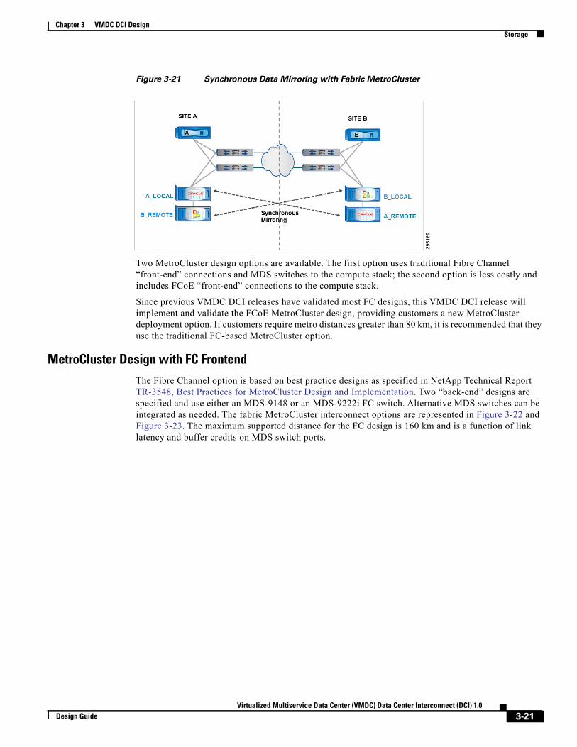
Chapter 3 VMDC DCI DesignStorage
Figure 3-21 Synchronous Data Mirroring with Fabric MetroCluster
Two MetroCluster design options are available. The first option uses traditional Fibre Channel “front-end” connections and MDS switches to the compute stack; the second option is less costly and includes FCoE “front-end” connections to the compute stack.
Since previous VMDC DCI releases have validated most FC designs, this VMDC DCI release will implement and validate the FCoE MetroCluster design, providing customers a new MetroCluster deployment option. If customers require metro distances greater than 80 km, it is recommended that they use the traditional FC-based MetroCluster option.
MetroCluster Design with FC FrontendThe Fibre Channel option is based on best practice designs as specified in NetApp Technical Report TR-3548, Best Practices for MetroCluster Design and Implementation. Two “back-end” designs are specified and use either an MDS-9148 or an MDS-9222i FC switch. Alternative MDS switches can be integrated as needed. The fabric MetroCluster interconnect options are represented in Figure 3-22 and Figure 3-23. The maximum supported distance for the FC design is 160 km and is a function of link latency and buffer credits on MDS switch ports.
3-21Virtualized Multiservice Data Center (VMDC) Data Center Interconnect (DCI) 1.0
Design Guide

Chapter 3 VMDC DCI DesignStorage
Figure 3-22 MetroCluster Design with FC Frontend
Figure 3-23 MetroCluster Design with FCoE Frontend
MetroCluster Design with FCoE Frontend
Figure 3-24 shows the Fibre Channel over Ethernet (FCoE) MetroCluster design. This design is based on a FlexPod validated system and includes FCoE “front-end” interfaces to the compute stack. In addition, Cisco Nexus 7000 VDCs are required to segment the “front-end” FCoE ports/traffic from IP ports/traffic. The “back-end” storage replication function is implemented with traditional FC and uses either an MDS-9148 or an MDS-9222i FC switch. Alternative MDS switches can be integrated as needed for the “back-end” connections. The maximum supported distance for the FCoE design is 80 km and is
3-22Virtualized Multiservice Data Center (VMDC) Data Center Interconnect (DCI) 1.0
Design Guide

Chapter 3 VMDC DCI DesignStorage
a function of link latency and queue depth on the Cisco Nexus 7000 F2 line card. Other FCoE switch options (such as Cisco Nexus 5K or Nexus 6K) and other Cisco Nexus 7000 line card options (such as M1, F1) do not have sufficient line card queue depth to support FCoE spanning 80km distances and are not recommended for metro distances.
Figure 3-24 NetApp Fabric MetroCluster Design with FCoE Frontend
Network Connectivity for Storage Access
During normal operations, each site primarily accesses its local controller, hence the local datastores. However, in case of a failure, the surviving controller takes over all storage presentation and serves data for all datastores over the configured storage protocols (NFS, Fibre channel, iSCSI). In the event of a partial rather than complete site failure, hosts in the affected DC will have to access their storage across the metro link. The network configuration therefore must allow both LAN as well as SAN access across both the data centers. To achieve redundancy and to support both IP and FC traffic, a separate IP/LAN and FCoE connection is required on Cisco Nexus 7000 switches. This is achieved by connecting the Cisco Nexus 7000s as shown in Figure 3-25.
Figure 3-25 Network and SAN connectivity
3-23Virtualized Multiservice Data Center (VMDC) Data Center Interconnect (DCI) 1.0
Design Guide

Chapter 3 VMDC DCI DesignStorage
By utilizing the IP and FCoE links between the two DCs (shown above), an ESXi host in either DC can access all the datastores on each of the controllers. The IP links can be configured as a layer-2 or layer-3 link. Since OTV is being utilized to extend layer-2 across the sites in this VMDC DCI release, the IP links could be a layer-3 routed link reachable through multiple hops. The FCoE link between the devices is multi-hop enabled (VE port).
SAN Design Details
For SAN connectivity, NetApp FAS uses an FCoE connection to the Cisco Nexus 7000. In each Cisco Nexus 7000, a storage VDC is created, and the local controller connects to both the Cisco Nexus 7000s as shown in Figure 3-26. On each of the sites, Cisco Nexus 7000-A acts as a SAN-A switch and Cisco Nexus 7000-B acts as a SAN-B switch. To provide FC connectivity between the sites, FCoE connections are configured between the Cisco Nexus 7000 storage VDCs.
Figure 3-26 SAN Connectivity
As shown in Figure 3-26, two redundant paths are configured between the two sites for SAN resiliency. The ports between the Cisco Nexus 7000 switches are configured as FCoE VE ports to enable multi-hop FCoE. Using this configuration, every ESXi host has access to both the NetApp controllers. The boot policies used in boot-from-SAN configuration are very similar to single-site FlexPod infrastructure. The fabric path to the local controller becomes the preferred path, and the fabric path to the remote controller is set up as a secondary path. This protects against a failure within the local fabric that renders the local controller inaccessible (cables, switch component, controller component).
Datastore Layout
As per VMware guidelines, virtual machine datastores are configured on both NetApp controllers. To avoid cross-DC traffic, DRS host affinity groups and rules are configured to keep VMs on the hosts located in the same site as the datastores. The boot LUNs for ESXi hosts are also configured on storage presented from the local FAS controller. Mirroring using SyncMirror is enabled, and both sites maintain synchronized copies of each other’s data as it is written. Figure 3-27 hows the datastore configuration for both the DCs.
3-24Virtualized Multiservice Data Center (VMDC) Data Center Interconnect (DCI) 1.0
Design Guide

Chapter 3 VMDC DCI DesignStorage
Figure 3-27 Datastore Layout
For more information about NetApp MetroCluster and MetroCluster in a FlexPod configuration, refer to:
• TR-3548, Best Practices for MetroCluster Design and Implementation
• FlexPod Data Center with Cisco Nexus 7000 and NetApp MetroCluster for Multisite Deployment
Less Stringent RTO/RPO Protection Using NetApp SnapMirrorSnapMirror provides array-based data replication between NetApp FAS controllers. Built on NetApp Snapshot™ technology, SnapMirror is an extremely efficient “thin replication” solution whereby only the 4KB blocks that have been changed or added since the previous update are replicated between systems. In addition, destination volumes can be thin provisioned and will only consume as much space as the source volume itself. SnapMirror is configured at the storage volume level and provides not only remote disaster recovery, but the capability to restore from the secondary system from any recovery points (SnapShots) created on the primary system; for example, if 100 SnapShots from the past 30 days are available on the primary, they are available on the secondary as well. SnapMirror supports the pre-seeding of destination targets using SnapMirror to tape. SnapMirror also supports the establishment of cascading replication between multiple systems for multi-hop protection. SnapMirror is easily configured using NetApp OnCommand® System Manager, Protection Manager, or the Data ONTAP® CLI.
SnapMirror relationships can be configured in three different modes, depending on the RPO requirements and the connectivity characteristics between sites. A single SnapMirror license per controller provides the ability to use any one or all of the replication modes as latency and bandwidth permits. SnapMirror Sync can meet RPO targets of zero data loss with updates sent to the destination as they occur, but requires a very low RTT value between source and destination; higher latency between sites can result in higher effective latency for the applications running on the source/production volume. SnapMirror Semi-Sync meets RPO targets of minor data loss up to approximately 10 seconds, while being able to tolerate 2x-5x the latency over the replication network compared to SnapMirror Sync. SnapMirror Async meets RPO targets of a minute or more and is supported for effectively any geographic distance. Because greater distances and therefor greater round trip latency will necessarily impact replication times, these factors need to be taken into consideration when designing the architecture of replication strategy (Table 3-1).
Table 3-1 Modes of Replication
Mode of Replication RPO RequirementsRound Trip Time BetweenPrimary and Secondary Sites
Effective SiteDistances
SnapMirror Sync Zero or near-zero 2 ms Metro
3-25Virtualized Multiservice Data Center (VMDC) Data Center Interconnect (DCI) 1.0
Design Guide

Chapter 3 VMDC DCI DesignStorage
For many protected workloads, SnapMirror Async is the appropriate replication mechanism by providing support for extended geographic distances, higher tolerance for network latency, higher RPO requirements, and granular control of those RPO requirements at the level of individual volumes. Each SnapMirror relationship, comprised of source and destination volumes, can be updated (replicated) on its own schedule as dictated by the RPO requirements of the customer’s data or application. In addition, each relationship can have its own parameters specified for rate limiting or network compression. SnapMirror Async provides the underlying storage replication used with VMware vCenter Site Recovery Manager in this VMDC DCI release.
SnapMirror network compression is a native feature of Data ONTAP which enables compression of over-the-wire data blocks during SnapMirror transfers. When enabled, free CPU cycles are used for a standard gzip algorithm to compress the data blocks on the source controller, and then to decompress the received data blocks on the destination controller. This compression does not affect data at rest.
Table 3-2 Supported SnapMirror Cascade Configurations
SnapMirror Sync/Semi-Sync SnapMirror Async Yes
SnapMirror Async SnapMirror Async Yes
SnapMirror Sync/Semi-Sync SnapMirror Sync/Semi-Sync No
SnapMirror Async SnapMirror Sync/Semi-Sync No
SnapMirror relationships can be single (source A to destination B), multiple (source A to destination B, source A to destination C), or cascading (source A to destination B, destination B to destination C). Cascading relationships for multi-hop replication are supported by SnapMirror in several configurations (Table 3-2).
Because destination data replicated via SnapMirror is in a read-only state while the relationship is in effect, the effective RTO is necessarily higher than when using SyncMirror and MetroCluster. Read-write access to the replicated volume can be provided using NetApp FlexClone technology, and this feature is a key enabler of test scenarios run Site Recovery Manager. In the case of data migration or disaster recovery, the storage administrator breaks the SnapMirror relationship and the destination volume is automatically promoted to a read-write copy, which can then be mapped to and accessed by clients.
For DR situations in which the primary storage is recovered, SnapMirror provides an efficient means of resynchronizing the primary and recovery sites. SnapMirror can resynchronize the two sites, transferring only changed and new data back to the primary site from the DR site by simply reversing the SnapMirror relationships.
For more information NetApp SnapMirror refer to:
• TR-3326, 7-Mode SnapMirror Sync and SnapMirror Semi-Sync Overview and Design Considerations
SnapMirror Semi-Sync Near-zero to minutes 5 ms – 10 ms Metro
SnapMirror Async Any
(Minutes to hours, or higher)
Any Any
(Metro or Geo)
Table 3-1 Modes of Replication
Mode of Replication RPO RequirementsRound Trip Time BetweenPrimary and Secondary Sites
Effective SiteDistances
SnapMirror Cascade Configuration Support
3-26Virtualized Multiservice Data Center (VMDC) Data Center Interconnect (DCI) 1.0
Design Guide

Chapter 3 VMDC DCI DesignVMware Redundancy and Workload Mobility Options
• TR-3446, 7-Mode SnapMirror Async Overview and Best Practices Guide
VMware Redundancy and Workload Mobility OptionsVMware vSphere 5.1 enables a number of VM redundancy and mobility capabilities. These features can enable live and cold VM migrations, as well as live and cold high availability and disaster recovery. Various options are available to achieve RPO/RTO targets, ranging from zero downtime and zero data loss to many minutes or hours of recovery time and data loss. Private and public cloud providers are increasingly using these hypervisor-based features to implement business continuity and workload mobility across metro and geo distant data centers. A brief description of vSphere 5.1 capabilities is provided below. The VMDC DCI release will use a subset of these features as highlighted later in this section.
VMware High Availability (HA) minimizes virtual machine downtime in a resource pool by monitoring hosts, virtual machines, or applications within virtual machines, then, in the event a failure is detected, restarting virtual machines on alternate hosts. Recovery time is typically within minutes. Resource pools for HA hosts can extend across metro distances.
Figure 3-28 VMware High Availability (HA)
VMware Fault Tolerance (FT) runs a secondary copy of a virtual machine on a secondary host and rapidly switches to that secondary copy in the event of failure of the primary host. Recovery time and data loss are typically near zero. Resource pools for FT hosts can extend across metro distances.
Note It is important to note that Microsoft Hyper-V DCI functionality will be covered in a separate addendum to this VMDC DCI release.
3-27Virtualized Multiservice Data Center (VMDC) Data Center Interconnect (DCI) 1.0
Design Guide

Chapter 3 VMDC DCI DesignVMware Redundancy and Workload Mobility Options
Figure 3-29 VMware FaultTolerance (FT)
VMware vMotion and Storage vMotion features allow running virtual machines and related storage to be migrated from one physical server to another with no downtime or no data loss. Resource pools for vMotion hosts can extend across metro distances.
Figure 3-30 VMware Live vMotion and Storage vMotion
VMware “Shared Nothing” vMotion is a feature that allows running virtual machines and related storage to be migrated from one physical server to another without the need of a shared storage device. These are live moves with no downtime or data loss. Resource pools for Shared Nothing-vMotion hosts can extend across metro distances.
3-28Virtualized Multiservice Data Center (VMDC) Data Center Interconnect (DCI) 1.0
Design Guide

Chapter 3 VMDC DCI DesignVMware Redundancy and Workload Mobility Options
Figure 3-31 VMware “Shared Nothing” Live vMotion
vSphere Metro Storage Cluster (vMSC) is a certified configuration designed to make sure of data high availability using a storage architecture that provides logical or physical site resiliency. ESXi hosts within each site are configured with access to storage in both sites, and hosts from both sites are included within the same vSphere HA cluster. With the certified storage array providing the data resiliency across sites, vSphere clusters provide the necessary HA at the compute or hypervisor level. To make sure that data access from each host does not incur a nonoptimum path across sites, DRS host affinity groups and rules are recommended to fence VMs so that the running instance remains local to its backing storage. The multi-site design must meet the following requirements:
• The maximum supported network latency between sites for the VMware® ESXi™ vMotion networks is 10ms round-trip time with VMware vSphere® Enterprise Plus Edition™ licenses; with lower edition licensing the maximum supported latency is only 10ms round-trip time.
• A minimum of 250 Mbps network bandwidth, configured with redundant links, is required for the ESXi vMotion network.
For more information on vMSC on NetApp refer to:
• TR-4128, vSphere 5 on NetApp MetroCluster Solution
• vSphere 5.x support with NetApp MetroCluster
vCenter Site Recovery Manager (SRM) is a disaster-recovery management product. It uses vSphere Replication and supports a broad set of storage-replication products to replicate virtual machines to a secondary site. It also provides a simple interface for setting up recovery plans that are coordinated across all infrastructure layers, replacing traditional error-prone run-books. Recovery plans can be tested nondisruptively as frequently as required to make sure that they meet business objectives. At the time of a site failover or workload migration, Site Recovery Manager automates both failover and failback processes, making sure of fast and highly predictable recovery point objectives (RPOs) and recovery time objectives (RTOs). Facilitating recovery with VMware Site Recovery Manager automation depends heavily on array or storage area network (SAN) replication to copy data between sites. SRM software executes on a SRM server or virtual machine at both the protected and recovery sites, but also requires a Virtual Center to run at the remote site.
Figure 3-32 shows a typical SRM environment with VMware vCenter Site Recovery Manager and NetApp FAS/V-Series Storage Systems.
3-29Virtualized Multiservice Data Center (VMDC) Data Center Interconnect (DCI) 1.0
Design Guide
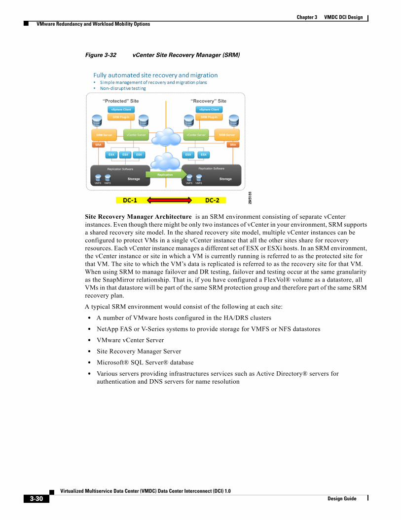
Chapter 3 VMDC DCI DesignVMware Redundancy and Workload Mobility Options
Figure 3-32 vCenter Site Recovery Manager (SRM)
Site Recovery Manager Architecture is an SRM environment consisting of separate vCenter instances. Even though there might be only two instances of vCenter in your environment, SRM supports a shared recovery site model. In the shared recovery site model, multiple vCenter instances can be configured to protect VMs in a single vCenter instance that all the other sites share for recovery resources. Each vCenter instance manages a different set of ESX or ESXi hosts. In an SRM environment, the vCenter instance or site in which a VM is currently running is referred to as the protected site for that VM. The site to which the VM’s data is replicated is referred to as the recovery site for that VM. When using SRM to manage failover and DR testing, failover and testing occur at the same granularity as the SnapMirror relationship. That is, if you have configured a FlexVol® volume as a datastore, all VMs in that datastore will be part of the same SRM protection group and therefore part of the same SRM recovery plan.
A typical SRM environment would consist of the following at each site:
• A number of VMware hosts configured in the HA/DRS clusters
• NetApp FAS or V-Series systems to provide storage for VMFS or NFS datastores
• VMware vCenter Server
• Site Recovery Manager Server
• Microsoft® SQL Server® database
• Various servers providing infrastructures services such as Active Directory® servers for authentication and DNS servers for name resolution
3-30Virtualized Multiservice Data Center (VMDC) Data Center Interconnect (DCI) 1.0
Design Guide

Chapter 3 VMDC DCI DesignVMware Redundancy and Workload Mobility Options
Figure 3-33 Typical SRM Environment
Figure 3-34 shows VMs that exist at the protected site 1, being replicated to the recovery site 2. For simplicity, this figure shows replication and protection of VMs going only in one direction, from site 1 to site 2. However, replication and protection of VMs can be performed in both directions, with different VMs in different datastores at each site that are configured to be recovered in the opposite site.
In an SRM environment, communication does not occur directly between the SRM servers; instead, SRM communication is performed by proxy through the vCenter Server at each site, as shown by the blue arrowed lines. The same is true of communication with the NetApp storage arrays. At no time does the SRM server in site 1 communicate with the FAS/V-Series controller in site 2. If you are working in the SRM interface at site 1 and you are performing some action that requires an operation be performed on the FAS/V-Series controller at site 2, the SRA command is sent by proxy through the vCenter Servers to the SRM server at site 2. The SRM server at site 2 then communicates with the local NetApp controller and sends the response back to the SRM server in site 1, again by proxy back through the vCenter Servers.
It’s important that the infrastructure services, such as authentication, name resolution, and VMware licensing, are active and available at both sites.
SnapMirror is used to replicate FlexVol volumes backing NFS or VMFS datastores from the primary site to the DR site.
VMware vSphere Replication provides a low-cost hypervisor-based data replication technique to create snapshots of virtual storage for use in a recovery process.
3-31Virtualized Multiservice Data Center (VMDC) Data Center Interconnect (DCI) 1.0
Design Guide

Chapter 3 VMDC DCI DesignVMware Workload Mobility Design
Figure 3-34 VMware vSphere Replication
VMware Workload Mobility DesignThe VMDC DCI release validated live and cold workload mobility scenarios across the Active-Active metro design and Active-Backup metro/geo design.
In the Active-Active Metro design, live workload mobility in which an active VM and related storage is moved from one metro data center to a different metro data center was implemented by:
• VMware vMotion spanning metro data centers using a stretched ESXi cluster and a single vCenter management extended across two metro data center sites.
• NetApp fabric MetroCluster performed synchronous storage replication of virtual machine datastores across metro data centers.
• Cisco Nexus 1000v Distributed Virtual Switches (DVS) span metro sites to support live vMotion workload mobility. In addition, all vMotion vmknics on a host should share a single DVS. Each vmknic's port group should be configured to use a different physical NIC as its active vmnic. In addition, all vMotion vmknics should be on the same vMotion network.
• For metro data centers with a 5ms RTT or less, any licensing edition of VMware vSphere is supported. For 5ms–10ms RTT, Enterprise Plus licensing is required to support metro vMotion.
• vMotion performance will increase as additional network bandwidth is made available to the vMotion network. Consider provisioning 10Gb vMotion network interfaces for maximum vMotion performance.
• Multiple vMotion vmknics can provide a further increase in network bandwidth available to vMotion.
• While a vMotion operation is in progress, ESXi opportunistically reserves CPU resources on both the source and destination hosts in order to make sure of the ability to fully utilize the network bandwidth. ESXi will attempt to use the full available network bandwidth regardless of the number of vMotion operations being performed. The amount of CPU reservation therefore depends on the number of vMotion NICs and their speeds; 10% of a processor core for each 1Gb network interface, 100% of a processor core for each 10Gb network interface, and a minimum total reservation of 30% of a processor core. Therefore, leaving some unreserved CPU capacity in a cluster can help make sure that vMotion tasks get the resources required to fully utilize available network bandwidth.
3-32Virtualized Multiservice Data Center (VMDC) Data Center Interconnect (DCI) 1.0
Design Guide

Chapter 3 VMDC DCI DesignVMware Workload Mobility Design
In the Active-Standby Metro/Geo design, Cold workload mobility in which a stopped VM is moved from one metro/geo data center to different metro/geo data center will be implemented by:
• VMware Site Recovery Manager spanning metro and geo data centers using separate ESXi clusters and separate vCenter server instances at each data center site.
• NetApp SnapMirror performs synchronous, semi-synchronous, or asynchronous storage replication of datastores between data centers to achieve RPO data loss targets that meet the application business requirements, but with a higher RTO than is provided by MetroCluster.
• Cisco Nexus 1000v Distributed Virtual Switches (DVS) implement separate DVS switches at each data center to manage workloads used in cold migration and disaster recovery scenarios.
• An SRM planned migration was used to invoke a cold workload migration. Planned migration makes sure of an orderly shutdown of virtual machines at the protected site, synchronizes the data with the failover site by making sure of complete replication of all data, and finally recovers the virtual machines at the failover site. Planned migration makes sure of application-consistent migration to the secondary site with no data loss.
• Site Recovery Manager supports configurations in which both sites are running active virtual machines that Site Recovery Manager can recover at the other site. In an active-active SRM scenario, users configure recovery plan work flows in one direction, from site 1 to site 2, for the protected virtual machines at site 1. Recovery plan work flows are configured in the opposite direction, from site 2 to site 1, for the protected virtual machines at site 2. The VMDC DCI system utilized an active/passive recovery scenario.
3-33Virtualized Multiservice Data Center (VMDC) Data Center Interconnect (DCI) 1.0
Design Guide

Chapter 3 VMDC DCI DesignVMware Workload Mobility Design
3-34Virtualized Multiservice Data Center (VMDC) Data Center Interconnect (DCI) 1.0
Design Guide

Virtualized Multiservice Data CDesign Guide
C H A P T E R 4
System Level Design ConsiderationsThe following system level design considerations are defined:
• System Scale Considerations, page 4-1
• System Availability, page 4-3
• Security, page 4-4
• Manageability, page 4-5
• Service Assurance and Monitoring, page 4-5
System Scale ConsiderationsSince this VMDC DCI release is based on the Fabric Path design validated in previous VMDC releases, most of the intra data center scale considerations remain the same as the VMDC 3.x release. The intra data center scaling is provided below. DCI specific scaling requirements are presented later in this section.
• VLAN Scale—In NX-OS releases 5.2.5 through 6.1, a maximum of 2000 FabricPath-encapsulated VLANs is supported. This figure is improved to 4000 VLANs in NX-OS 6.2. However, it is important to note that this by definition is a one-dimensional figure, which does not factor in inter-related (Layer 2 to Layer 3) end-to-end traffic flow considerations such as FHRP constraints per module or per node. In practice, overall system VLAN scaling will be constrained by the effect of ARP learning rates on system convergence and FHRP (HSRP or GLBP) groups per module or interface, and per node. Regarding the latter, HSRP support per module is currently 500 and 1000 per system, with aggressive timers, or 2000 per system, with default timers; GLBP is 200 per module and 500 per system, with aggressive timers, or 1000 per system, with default timers.
• Switches per FabricPath Domain—NX-OS 5.2 supports a maximum of 64 switch ids; NX-OS 6.0 a maximum of 128; NX-OS 6.2 a maximum of 256.
• Port Density per FabricPath Node—At 48 ports per module, the F2 line cards provide up to 768 10 or 1 GE ports per switch (N7018), while the F1 cards provide up to 512 10GE ports (N7018). Again, these are uni-dimensional figures, but serve to give a theoretical maximum in terms of one measure of capacity. Currently the Nexus 7000 FabricPath limitation is 256 core ports or 384 edge ports.
• MAC Address (Host) Scale—All FabricPath VLANs use conversational MAC address learning. Conversational MAC learning consists of a three-way handshake. This means that each interface learns only those MAC addresses for interested hosts, rather than all MAC addresses in the VLAN.
4-1enter (VMDC) Data Center Interconnect (DCI) 1.0

Chapter 4 System Level Design ConsiderationsSystem Scale Considerations
This selective learning allows the network to scale beyond the limits of individual switch MAC address tables. Classical Ethernet VLANs use traditional MAC address learning by default, but the CE VLANs can be configured to use conversational MAC learning.
• ARP Learning Rate—As noted, ARP learning rates on layer 3 edge nodes affect system convergence for specific failure types. ARP learning rates of 100/second were observed on the Nexus 7000 aggregation-edge nodes during system validation. With tuning, this was improved to 250-300/second.
• Tenancy—The validated tenancy in the 3.0.1 Release was 32. However this does not represent the maximum scale of the architecture models. Within the models addressed in this release, several factors will constrain overall tenancy scale. These are - 1) VRFs per system. Currently, up to 1000 VRFs are supported per Nexus 7000 aggregation edge node, but then additional factors include 2) End-to-end VLAN support (i.e., affected by FHRP (HSRP or GLBP) groups per card and per system; and 3) 250 contexts per ASA FW appliance – one may increment this up by adding appliances if needed.
• N7k Spine Nodes—Sup2/F2E cards may be utilized (16k MACs supported); for N5k leaf nodes, 24k MACs are supported; for N6k spine/leaf option, 64K MACs are currently supported (increasing to 128k+ in future s/w releases).
Note MAC address capacity is a consideration for support of inter-UCS, inter-leaf node logical segments, which must traverse the FabricPath fabric; otherwise, conversational learning insures that host MACs do not need to be maintained within the FabricPath fabric.
• 2200 FEX Systems—(i.e., as in VMDC 3.0/3.0.1) will be required within the architecture, to provide support for 1GE bare metal server connectivity. These may be N5k, N7k, N6k -attached; in the SUT we can simply pick one method – N6k-attached - as we have validated with the first two types in previous VMDC 3.X releases.
Additional scale parameters for this VMDC DCI release include support for metro/geo LAN extensions using OTV.
• OTV Scale—The NX-OS 6.2 release will increase scaling for OTV as specified below. Most of the scale testing to support this increased capacity will be validated by product teams. For this release, OTV scaling will be limited to the number of VLANs/MACs required by multiple applications under test. These applications include a single tier application and a multi-tier application, and will be replicated across multiple tenants (3 or more). Background VLAN traffic can be added to the OTV links to emulate peak workloads.
Figure 4-1 OTV Scale
4-2Virtualized Multiservice Data Center (VMDC) Data Center Interconnect (DCI) 1.0
Design Guide
Chapter 4 System Level Design ConsiderationsSystem Availability
• Workload and Tenant Scaling—Test workloads will be implemented to emulate a single tier application and a multi-tier application. These applications will be replicated across multiple tenants to emulate a realistic customer environment. Live and Cold workload migrations were performed across these tenants to validate tenant isolation, traffic isolation, service isolation across DCI components.
• New Data Center capacity for Business Continuity—New data center capacity to accommodate the recovery environment (VMs, servers, storage, network, services) must be planned for at recovery data center sites. The total scale and capacity of any one physical site will include both “normal application capacity” and “recovery/backup capacity”. The resultant scale of this design must fall within the standard scaling limitations as described previously. No additional validation is required in this area. An important Business requirement however, is to utilize the extra recovery capacity during normal operations for other business functions. To that end, VMDC DCI demonstrated how VMware SRM can “reclaim” server capacity within an ESX cluster on demand for the Cold workload Mobility use case. This can be accomplished by executing any “test application” on servers within the SRM recovery cluster. SRM has the ability to shut down and purge those recovery servers of loaded applications (reclaim) prior to the actual Cold Migration of the application under test.
System AvailabilityThe following methods are used to achieve High Availability within the VMDC architecture:
• Routing and Layer 3 redundancy at the core and aggregation/leaf nodes of the infrastructure. This includes path and link redundancy, non-stop forwarding and route optimization.
• In the “Typical Data Center” (2-node spine topology) VPC+ is configured on inter-spine peer-links and utilized in conjunction with HSRP to provide dual-active paths from access edge switches across the fabric.
• Layer 2 redundancy technologies are implemented through the FabricPath domain and access tiers of the infrastructure. This includes ARP synchronization in VPC/VPC+-enabled topologies to minimize flooding of unknown unicast and re-convergence; ECMP; utilization of port-channels between FabricPath edge/leaf and spine nodes to minimize Layer 2 IS-IS adjacency recalculations; and IS-IS SPF tuning, CoPP, GLBP and HSRP timer tuning on aggregation edge nodes, again to minimize system re-convergence.
• Active/Active (active/standby of alternating contexts) on services utilized in the architecture.
• Clustered HA and ECLB (equal cost load balancing) for appliance-based firewall services.
• Hardware and Fabric redundancy throughout.
• (VEM) MCEC uplink redundancy and VSM redundancy within the virtual access tier of the infrastructure.
• Within the compute tier of the infrastructure, port-channeling, NIC teaming and intra-cluster HA through utilization of VMware VMotion.
• NetApp Fabric MetroCluster with SyncMirror is configured to provide full-site data storage resiliency.
All service appliance resiliency implementations will be contained within a single data center since neither ASA or Citrix SLB currently support clustering over a metrodistance at this time.
4-3Virtualized Multiservice Data Center (VMDC) Data Center Interconnect (DCI) 1.0
Design Guide

Chapter 4 System Level Design ConsiderationsSecurity
Figure 4-2 Service Appliance Contained to Single Site
Note It is important to note that LISP will be added in a future VMDC DCI release to support automated tracking of moving services and applications, and the redirection of external flows to the correct data center.
SecurityThe proven security framework from the previous VMDC systems is leveraged for tenancy separation and isolation. Security related considerations include:
• Aggregation Layer (Layer 3) Separation—VRF-lite implemented on aggregation-edge nodes at the aggregation layer provides per tenant isolation at Layer 3, with separate dedicated per-tenant routing and forwarding tables on the inside interfaces of firewall contexts. All inter-tenant traffic has to be routed at the outside interfaces on the Firewall that resides in the global VRF. Policies can be applied on the firewall to restrict inter-tenant communication. Layer 3 separation and tenant isolation has been verified across DCI extensions in multi-site topologies.
• Access and Virtual Access Layer (Layer 2) Separation—VLAN IDs and the 802.1q tag provide isolation and identification of tenant traffic across the Layer 2 domain, and more generally, across shared links throughout the infrastructure. Layer 2 separation of tenant traffic has been verified across DCI extensions in multi-site topologies.
• Network Services Separation (Services Core, Compute)—On physical appliance or service module form factors, dedicated contexts or zones provide the means for virtualized security, load balancing, NAT, and SSL offload services, and the application of unique per-tenant policies at the VLAN level of granularity. Similarly, dedicated virtual appliances (i.e., in vApp form) provide for unique per-tenant services within the compute layer of the infrastructure at the virtual machine level of granularity. Secure network services separation on physical and virtual appliances has been verified across DCI extensions in multi-site topologies.
• Storage—This VMDC design revision uses NetApp for NFS storage, which enables virtualized storage space such that each tenant (application or user) can be separated with use of IP spaces and VLANs mapped to network layer separation. In terms of SANs, this design uses Cisco MDS 9500
4-4Virtualized Multiservice Data Center (VMDC) Data Center Interconnect (DCI) 1.0
Design Guide

Chapter 4 System Level Design ConsiderationsManageability
for Block Storage. This allows for Fiber Channel (FC) access separation at the switch port level (VSAN), Logical path access separation on the path level (WWN/Device Hard Zoning), and at the virtual media level inside the Storage Array (LUN Masking and Mapping).
ManageabilityThis architecture leverages Cisco Intelligent Automation for Cloud (CIAC) and BMC Cloud Lifecycle Management (CLM) for automated service orchestration and service provisioning. Information about CIAC can be found in Intelligent Automation for Cloud. CLM was addressed in previous system releases (VMDC 2.0 and updated in the VMDC 2.2 release). Additional documentation can be found on Design Zone at Cloud Orchestration with BMC CLM.
Service Assurance and MonitoringService assurance is generally defined as the application of policies and processes to ensure that network services meet predefined service quality levels for optimal subscriber experiences. Service assurance enables SPs to control traffic flows, identify faults, and resolve issues in a timely manner to minimize service downtime. Service assurance also includes policies and processes to proactively diagnose and resolve service quality degradations or device malfunctions before subscribers are impacted.
In VMDC DCI, network service assurance encompasses the following concepts:
• Traffic Engineering, page 4-5
• QoS Framework, page 4-8
Traffic EngineeringTraffic engineering is a method of optimizing network performance by dynamically analyzing, predicting and regulating the behavior of transmitted data.
Port-channels are frequently deployed for redundancy and load sharing. Because the Nexus 1000V is an end-host switch, network administrators can use different approach than those used on physical switches, implementing a port-channel mechanism in one of the following modes:
• Standard Port-Channel—The port-channel is configured on the Nexus 1000V and on upstream switches
• Special Port-Channel—The port-channel is configured only on the Nexus 1000V; there is no need to configure anything upstream. Two options are available: MAC pinning and vPC host mode.
Regardless of mode, port-channels are managed using standard port-channel CLI, but each mode behaves differently. Refer to Nexus 1000V Port-Channel Configurations for details.
The VMDC virtual access layer design uses vPC host mode and then uses MAC pinning to select specific links from the port channel. As discussed in previous system releases, multiple port-channels can be used for a more granular approach for uplink traffic management on the Nexus 1000V. These options are shown in Figure 4-3 and Figure 4-4.
4-5Virtualized Multiservice Data Center (VMDC) Data Center Interconnect (DCI) 1.0
Design Guide
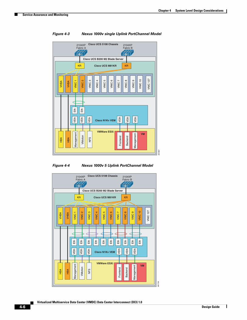
Chapter 4 System Level Design ConsiderationsService Assurance and Monitoring
Figure 4-3 Nexus 1000v single Uplink PortChannel Model
2918
67
VN
IC 1
27
VN
IC 1
0
VN
IC 9
VN
IC 8
VN
IC 7
VN
IC 6
VN
IC 5
VN
IC 4
VN
IC 3
VN
IC 2
VN
IC 1
NF
S
VM
otio
n
Man
agem
ent
Man
agem
ent
Bac
kend
Fro
nten
d
VH
BA
VH
BA
HB
A
HB
A
Eth
Eth
VE
th
VE
th
VE
th
VE
th
VE
th
VE
th
Cisco UCS M81KR
Cisco UCS B200 M2 Blade Server
Cisco UCS 5108 Chassis2104XPFabric A
2104XPFabric B
Cisco N1Kv VEM
VMWare ESXiVM
KR KR
Figure 4-4 Nexus 1000v 5 Uplink PortChannel Model
2917
34
VN
IC 1
27
VN
IC 1
0
VN
IC 9
VN
IC 8
VN
IC 7
VN
IC 6
VN
IC 5
VN
IC 4
VN
IC 3
VN
IC 2
VN
IC 1
NF
S
VM
otio
n
Man
agem
ent
Man
agem
ent
Bac
kend
Fro
nten
d
VH
BA
VH
BA
HB
A
HB
A
Eth
Eth
Eth
Eth
Eth
Eth
Eth
Eth
Eth
VE
th
VE
th
VE
th
VE
th
VE
th
VE
th
Eth
Cisco UCS M81KR
Cisco UCS B200 M2 Blade Server
Cisco UCS 5108 Chassis2104XPFabric A
2104XPFabric B
Cisco N1Kv VEM
VMWare ESXiVM
KR KR
4-6Virtualized Multiservice Data Center (VMDC) Data Center Interconnect (DCI) 1.0
Design Guide
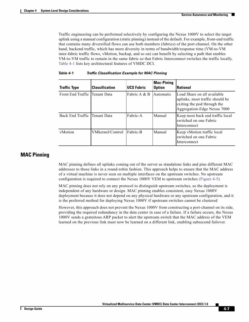
Chapter 4 System Level Design ConsiderationsService Assurance and Monitoring
Traffic engineering can be performed selectively by configuring the Nexus 1000V to select the target uplink using a manual configuration (static pinning) instead of the default. For example, front-end traffic that contains many diversified flows can use both members (fabrics) of the port-channel. On the other hand, backend traffic, which has more diversity in terms of bandwidth/response time (VM-to-VM inter-fabric traffic flows, vMotion, backup, and so on) can benefit by selecting a path that enables VM-to-VM traffic to remain in the same fabric so that Fabric Interconnect switches the traffic locally. Table 4-1 lists key architectural features of VMDC DCI.
Table 4-1 Traffic Classification Example for MAC Pinning
Traffic Type Classification UCS FabricMac-PiningOption Rational
Front End Traffic Tenant Data Fabric A & B Automatic Load Share on all available uplinks, most traffic should be exiting the pod through the Aggregation-Edge Nexus 7000
Back End Traffic Tenant Data Fabric-A Manual Keep most back end traffic local switched on one Fabric Interconnect
vMotion VMkernel/Control Fabric-B Manual Keep vMotion traffic local switched on one Fabric Interconnect
MAC Pinning
MAC pinning defines all uplinks coming out of the server as standalone links and pins different MAC addresses to those links in a round-robin fashion. This approach helps to ensure that the MAC address of a virtual machine is never seen on multiple interfaces on the upstream switches. No upstream configuration is required to connect the Nexus 1000V VEM to upstream switches (Figure 4-5).
MAC pinning does not rely on any protocol to distinguish upstream switches, so the deployment is independent of any hardware or design. MAC pinning enables consistent, easy Nexus 1000V deployment because it does not depend on any physical hardware or any upstream configuration, and it is the preferred method for deploying Nexus 1000V if upstream switches cannot be clustered
However, this approach does not prevent the Nexus 1000V from constructing a port-channel on its side, providing the required redundancy in the data center in case of a failure. If a failure occurs, the Nexus 1000V sends a gratuitous ARP packet to alert the upstream switch that the MAC address of the VEM learned on the previous link must now be learned on a different link, enabling subsecond failover.
4-7Virtualized Multiservice Data Center (VMDC) Data Center Interconnect (DCI) 1.0
Design Guide
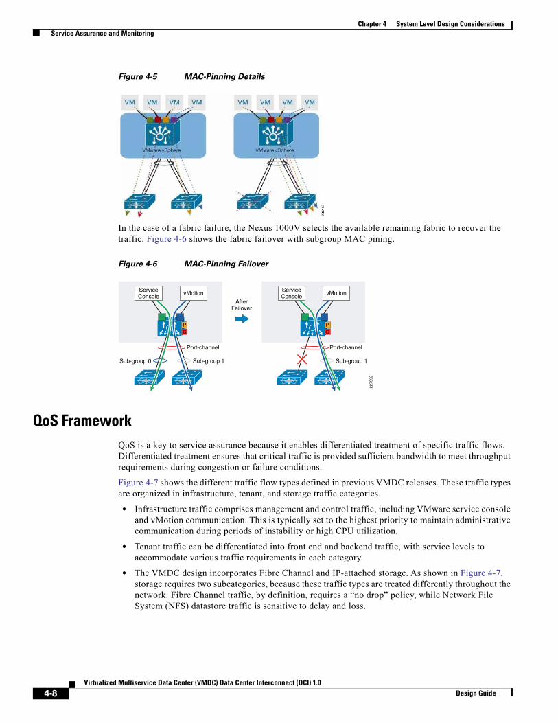
Chapter 4 System Level Design ConsiderationsService Assurance and Monitoring
Figure 4-5 MAC-Pinning Details
In the case of a fabric failure, the Nexus 1000V selects the available remaining fabric to recover the traffic. Figure 4-6 shows the fabric failover with subgroup MAC pining.
Figure 4-6 MAC-Pinning Failover
Port-channel
Sub-group 1Sub-group 0
AfterFailover
2279
92
PC
ServiceConsole vMotion
Port-channel
Sub-group 1
PC
ServiceConsole vMotion
QoS FrameworkQoS is a key to service assurance because it enables differentiated treatment of specific traffic flows. Differentiated treatment ensures that critical traffic is provided sufficient bandwidth to meet throughput requirements during congestion or failure conditions.
Figure 4-7 shows the different traffic flow types defined in previous VMDC releases. These traffic types are organized in infrastructure, tenant, and storage traffic categories.
• Infrastructure traffic comprises management and control traffic, including VMware service console and vMotion communication. This is typically set to the highest priority to maintain administrative communication during periods of instability or high CPU utilization.
• Tenant traffic can be differentiated into front end and backend traffic, with service levels to accommodate various traffic requirements in each category.
• The VMDC design incorporates Fibre Channel and IP-attached storage. As shown in Figure 4-7, storage requires two subcategories, because these traffic types are treated differently throughout the network. Fibre Channel traffic, by definition, requires a “no drop” policy, while Network File System (NFS) datastore traffic is sensitive to delay and loss.
4-8Virtualized Multiservice Data Center (VMDC) Data Center Interconnect (DCI) 1.0
Design Guide

Chapter 4 System Level Design ConsiderationsService Assurance and Monitoring
Figure 4-7 Traffic FlowTypes
2951
86
Infrastructure
Tenant
Front End TrafficDifferentiatedBandwidthGuarantee
BandwidthGuarantee
MissionCritical
No Drop
Back End Traffic
Storage
Control TrafficNexus 1K ManagementService Console VMAdminUCS (kvm/ssh/web)5K/7K/Storage (access/web/ssh)
VMware vMotion
FCOE
IP Storage: NFS Datastore Time Sensitive
To provide differentiated services, VMDC leverages the following QoS functionality:
• Traffic (Classification and Marking)
• Congestion Management and Avoidance (Queuing, Scheduling, and Dropping)
• Traffic Conditioning (Shaping and Policing)
Classification and Marking
Classification and marking enables networks using QoS to identify traffic types based on source packet headers (L2 802.1p CoS and Differentiated Services Code Point (DSCP) information), and assign specific markings to those traffic types for appropriate treatment as the packets traverse network nodes. Marking (coloring) is the process of setting the value of DSCP, MPLS EXP, or Ethernet L2 class of service (CoS) fields so that traffic can later easily be identified. using simple classification techniques. Conditional marking is used to designate in-contract (“conform”) or out-of-contract ("exceed") traffic.
As in previous releases, the traffic service objectives translate to support for three broad traffic categories:
1. Infrastructure
2. Tenant service classes (three data; two multimedia priority)
3. Storage
Figure 4-8 provides a more granular description of the requisite traffic classes, characterized by their DSCP markings and per-hop behavior (PHB) designations. This represents a normalized view across validated VMDC and HCS reference architectures in the context of an eight-class IP/NGN aligned model
4-9Virtualized Multiservice Data Center (VMDC) Data Center Interconnect (DCI) 1.0
Design Guide

Chapter 4 System Level Design ConsiderationsService Assurance and Monitoring
Figure 4-8 VMDCTraffic Classes (8-Class Reference)
Note that in newer datacenter QoS models, CoS 3 is reserved for lossless data (FCoE). However, in older WAN/Campus QoS services models, CoS 3 is used for VOIP signaling. The table above assumes that FCOE traffic will be localized to the UCS and Ethernet-attached Storage systems, thus enabling the use of CoS 3 for VoIP signaling traffic within the DC QoS domain. Classification values may need to be tweaked per traffic characteristics: for example CoS value 4 could potentially be used for VoIP call control if video streams are not deployed.
It is a general best practice to mark traffic at the source-end system or as close to the traffic source as possible in order to simplify the network design. However, if the end system is not capable of marking or cannot be trusted, one may mark on ingress to the network. In the VMDC QoS framework the Cloud Data Center represents a single QoS domain, with the Nexus 1000V forming the "southern" access edge, and the ASR 9000 or ASR 1000 forming the "northern" DC PE/WAN edge. These QoS domain edge devices will mark traffic, and these markings will be trusted at the nodes within the data center infrastructure; in other words, they will use simple classification based on the markings received from the edge devices. Note that where VM-FEX adapters are utilized, marking is implemented on the UCS Fabric Interconnects; in contrast to the Nexus 1000v implementation, there is no ability to conditionally mark-down CoS in the event of congestion.
In VMDC DCI, the assumption is that the DSCP values will not be altered. Intermediate nodes would ideally support QoS transparency, such that CoS values would not need to be re-marked. That said, if QoS transparency is not supported on a particular node within the QoS domain, it will be necessary to workaround this gap by re-marking. VMDC DCI verified that all QoS packets markings are preserved across DCI extensions.
Queuing, Scheduling, and Dropping
In a router or switch, the packet scheduler applies policy to decide which packet to dequeue and send next, and when to do it. Schedulers service queues in different orders. The most frequently used are:
• First in, first out (FIFO)
• Priority scheduling (also called priority queuing)
• Weighted bandwidth
4-10Virtualized Multiservice Data Center (VMDC) Data Center Interconnect (DCI) 1.0
Design Guide

Chapter 4 System Level Design ConsiderationsService Assurance and Monitoring
We use a variant of weighted bandwidth queuing called class-based weighted fair queuing/low latency queuing (CBWFQ/LLQ) on the Nexus 1000V at the southern edge of the data center QoS domain. At the ASR 9000 or ASR 1000 northern data center WAN edge, we use priority queuing (PQ)/CBWFQ to bound delay and jitter for priority traffic while supporting weighted bandwidth allocation for the remaining data traffic classes.
Queuing mechanisms manage the front of a queue, while congestion avoidance mechanisms manage the back of a queue. Because queue depths are limited, dropping algorithms, which drop packets as queue depths build, are used to avoid congestion. Two dropping algorithms are commonly used: weighted tail drop (often for VoIP or video traffic) or weighted random early detection (WRED), typically for data traffic classes. As in previous releases, WRED is used to drop out-of-contract data traffic (CoS 1) before in-contract data traffic (Gold and CoS 2), and for Bronze/Standard traffic (CoS 0) in the event of congestion.
Defining an end-to-end QoS architecture can be challenging because not all nodes in a QoS domain have consistent implementations. In the cloud data center QoS domain, we run the gamut from systems that support 16 queues per VEM (Nexus 1000V) to four internal fabric queues (Nexus 7000). This means that traffic classes must be merged on systems that support less than eight queues. Figure 4-9 shows the class-to-queue mapping that applies to the cloud data center QoS domain in the VMDC 2.2 reference architecture, in the context of alignment with either the HCS reference model or the more standard NGN reference.
Figure 4-9 VMDC Class-to-Queue Mapping
Note that the Nexus 2000 Fabric Extender provides only two user queues for QoS support: one for all no-drop classes and the other for all drop classes. The classes configured on its parent switch are mapped to one of these queues; traffic for no-drop classes is mapped one queue and traffic for all drop classes is mapped to the other. Egress policies are also restricted to these classes. Further, at this writing, queuing is not supported on Nexus 2000 host interface ports when connected to an upstream Nexus 7000 switch. Traffic is sent to the default fabric queue on the Nexus 7000, and queuing must be applied on FEX trunk
4-11Virtualized Multiservice Data Center (VMDC) Data Center Interconnect (DCI) 1.0
Design Guide

Chapter 4 System Level Design ConsiderationsService Assurance and Monitoring
(network interface) ports. Future NX-OS releases will feature enhanced Nexus 7000 support for FEX QoS, adding network QoS and default queuing policy support on downstream Nexus 2000 host interfaces.
Before NX-OS release 6.1.3, only two ingress queues are supported on the F2/F2E Nexus 7000 line cards. Release 6.1.3 adds support for four ingress queues. These line cards support four egress queues.
Shaping and Policing
Policing and shaping are used to enforce a maximum bandwidth rate (MBR) on a traffic stream; while policing effectively does this by dropping out-of-contract traffic, shaping does this by delaying out-of-contract traffic. VMDC uses policing in and at the edges of the cloud data center QoS domain to rate-limit data and priority traffic classes. At the data center WAN edge/PE, hierarchical QoS (HQoS) may be implemented on egress to the cloud data center; this uses a combination of shaping and policing in which L2 traffic is shaped at the aggregate (port) level per class, while policing is used to enforce per-tenant aggregates.
Sample bandwidth port reservation percentages are shown in Figure 4-10.
Figure 4-10 Sample Bandwidth Port Reservations
4-12Virtualized Multiservice Data Center (VMDC) Data Center Interconnect (DCI) 1.0
Design Guide

Virtualized Multiservice Data CDesign Guide
C H A P T E R 5
Infrastructure Management ToolsThe following Information management tools were used in VMDC DCI.• UCSM, page 5-1
• VNMC, page 5-2
• DCNM, page 5-2
• VMware vCenter, page 5-3
UCSMCisco Unified Computing System (UCS) Manager provides unified, embedded management of all software and hardware components in the Cisco UCS. It controls multiple chassis and manages resources for thousands of virtual machines.
Through its unified, embedded, policy-based, and ecosystem-friendly approach, Cisco UCS Manager helps reduce management and administration expenses, which are among the largest items in most IT budgets.
Cisco UCS Manager supports data center automation, helping increase operational agility and scalability, while reducing risk. It provides policy-based management with service templates and service profiles.
Cisco UCS Manager offers the following benefits:• A unified embedded management interface that integrates server, network, and storage access
• Policy and model-based management with service profiles that improves agility and reduces risk
• Auto discovery to detect, inventory, manage, and provision system components that are added or changed
• A comprehensive open XML API, which facilitates integration with third-party systems management tools
• Role-based administration that builds on existing skills and supports collaboration across disciplines
For further details refer to the Cisco UCS Manager Configuration Guides.
5-1enter (VMDC) Data Center Interconnect (DCI) 1.0

Chapter 5 Infrastructure Management ToolsVNMC
VNMCCisco Virtual Network Management Center (VNMC) provides centralized multi device and policy management for Cisco network virtual services. The product addresses those issues by automating processes, freeing staff to focus on optimizing the network environment. Cisco VNMC supports greater scalability along with standardization and consistent execution of policies.
When combined with the Cisco Nexus 1000V Switch, ASA 1000V Cloud Firewall, or the Cisco Virtual Security Gateway (VSG), you can implement the solution to provide
• Rapid and scalable deployment through dynamic, template-driven policy management based on security profiles
• Easy operational management through XML APIs to help enable integration with third-party management and orchestration tools
• A non-disruptive administration model that enhances collaboration across security and server teams while maintaining administrative separation and reducing administrative errors
Cisco VNMC operates in conjunction with the Cisco Nexus 1000V Virtual Supervisor Module (VSM) to improve operations and collaboration across IT. It streamlines the services performed by security, network, and server administrators.
This solution allows the security administrator to author and manage security profiles and Cisco Virtual Security Gateway (VSG) instances through the VNMC programmatic interface with Cisco Nexus 1000V. Cisco VSG provides trusted multi-tenant access with granular, zone-based, and context-aware security policies.
Cisco VNMC also manages the Cisco ASA 1000V Cloud Firewall to enable rapid and scalable security at the edge through dynamic, template-driven policy management.
For more information refer to the Cisco Virtual Network Management Center.
DCNMCisco Prime Data Center Network Manager (DCNM) is designed to help you efficiently implement and manage virtualized data centers. It includes a feature-rich, customizable dashboard that provides visibility and control through a single pane of glass to Cisco Nexus and MDS products. DCNM optimizes the overall uptime and reliability of your data center infrastructure and helps improve business continuity. This advanced management product:
• Automates provisioning of data center LAN and SAN elements
• Proactively monitors the SAN and LAN, and detects performance degradation
• Helps secure the data center network
• Eases diagnosis and troubleshooting of data center outages
• Simplifies operational management of virtualized data centers
This provides the following benefits:
• Faster problem resolution
• Intuitive domain views that provide a contextual dashboard of host, switch, and storage infrastructures
• Real-time and historical performance and capacity management for SANs and LANs
• Virtual-machine-aware path analytics and performance monitoring
5-2Virtualized Multiservice Data Center (VMDC) Data Center Interconnect (DCI) 1.0
Design Guide

Chapter 5 Infrastructure Management ToolsVMware vCenter
• Easy-to-use provisioning of Cisco NX-OS features with pre configured, customized templates
• Customized reports which can be scheduled at certain intervals
DCNM can be used to configure and manage VMDC technologies such as:
• Cisco virtual PortChannel (vPC)
• Virtual device context (VDC)
• Cisco FabricPath
• Fibre Channel over Ethernet (FCoE)
• Fabric zoning
• Virtual SANs (VSANs)
For further details refer to Cisco Prime Data Center Network Manager Configuration Guides.
VMware vCenterVMware vCenter Server provides centralized visibility and proactive management for the VMDC virtual infrastructure.
Centralized Control and Visibility
• vSphere Web Client enables managing the essential functions of vSphere from a browser
• Hardware monitoring with CIM SMASH enables alarms when hardware failures of key components
• Storage maps and reports convey storage usage, connectivity and configuration.
• Customizable topology views give you visibility into storage infrastructure and assist in diagnosis and troubleshooting of storage issues.
Proactive Management
• Host Profiles standardize and simplify how you configure and manage ESXi host configurations
• Capture the blueprint of a known, validated configuration—including networking, storage and security settings; and deploy it to many hosts, simplifying setup
• Host profile policies can also monitor compliance
Configuration, Compliance Chores
• Resource Management for Virtual Machines—Allocate processor and memory resources to virtual machines running on the same physical servers.
• Establish minimum, maximum, and proportional resource shares for CPU, memory, disk and network bandwidth.
• Dynamic Allocation of Resources—vSphere DRS continuously monitors utilization across resource pools and intelligently allocates available resources among virtual machines based on pre-defined rules that reflect business needs and changing priorities.
• Energy Efficient Resource Optimization—vSphere Distributed Power Management continuously monitors resource requirements and power consumption across a DRS cluster.
Automatic restart of virtual machines with vSphere HA
For more information on VMware vCenter Server refer to the VMware vSphere 5.1 vCenter Documentation.
5-3Virtualized Multiservice Data Center (VMDC) Data Center Interconnect (DCI) 1.0
Design Guide

Chapter 5 Infrastructure Management ToolsNetApp OnCommand System Manager
NetApp OnCommand System ManagerNetApp OnCommand® System Manager is a simple yet powerful browser-based management tool that enables administrators to easily con?gure and manage individual NetApp storage systems or clusters of systems. System Manager is optimized for IT generalists who need streamlined management, an easy-to-use GUI, and best-practice work flows so they can manage their storage like an expert.
System Manager lets administrators easily control the powerful capabilities and components of NetApp storage systems: flash, disks, pooled storage, shares/exports, deduplication, compression, Snapshot™ copies, SnapMirror®, SnapVault®, and network configuration. Storage management of both SAN (iSCSI, FC, FCoE) and NAS (SMB/CIFS, NFS) protocols is provided within same interface.
OnCommand System Manager provides:
• A single management interface for all NetApp FAS or V-Series storage running 7-mode or clustered Data ONTAP
• Simple-to-use, workflow-based wizards to automate the most common storage configuration and management tasks
• A dashboard unifying important system information including system alerts, alarms, and storage capacity
• Real-time system performance displayed in a single pane including CPU utilization, I/O throughput, operations, and latency
System Manager is included without charge with the purchase of NetApp FAS or V-series storage hardware.
More information on OnCommand System Manager is available here:
• Datasheet
• Documentation Production Library
5-4Virtualized Multiservice Data Center (VMDC) Data Center Interconnect (DCI) 1.0
Design Guide