Embed Size (px)
Citation preview

Virtual user interface for industrial robots off-line programming &
simulation and video cam on-line remote operation
POPA STELIAN, NICOLESCU ADRIAN, IVAN MARIO, PASCU NICOLETA
Machines and Manufacturing Systems
University POLITEHNICA of Bucharest
313 Splaiul Independentei, Sector 6, Bucharest, CP 060042
ROMANIA
[email protected], [email protected], [email protected],
[email protected], www.upb.ro
Abstract: - This paper presents the main development steps of a virtual user interface dedicated for industrial
robot’s off-line programming and simulation as well as remote on-line operation of a video cam, both of them
integrated in the same software platform, as backgrounds of a virtual robotics laboratory developed inside
Microsoft Robotics Developer Studio (MRDS). There are successively presented overall hardware – software
concept, as well as stages of development for: the virtual prototype of existing robot developed in CATIA V5
solid modeler, the decomposition of IR’s virtual prototype in cinematic modules and their transformation in
Blender software for achieving appropriate file types to be imported in MRDS, the redefinition of cinematic
modules in MRDS environment as well as final results obtained by implementation of the direct and inverse
cinematic algorithms for off-line IR’s programming and simulation. Complementary to previously mentioned
facilities, the software module for remote on-line operation of the video cam monitoring the activity of the
virtual laboratory is illustrated too.
Key-Words: - industrial robotics, remote operation, simulation, virtual laboratory, MRDS
1 Introduction
Virtual laboratories represent today the most
efficient and modern modality for sharing hardware
resources existing in a single laboratory, training
office or research facility. For getting access as well
as operation of existing hardware facilities the most
important issue is to have on disposal a dedicated
user interface able to allow maneuvering but in the
meantime preserving the security of the whole set of
hardware facilities that are to be operated. From
these points of view robotics laboratories have
specificity in operation and involve configuration of
the specific user interface, a possible approach to
solve these problems being the results of the works
presented in this paper.
2 Minimum required hardware /
software structure of virtual lab
Different ways of developing such software &
hardware platform were analysed [1], [2], [3], [4]
and finally the following conclusions were revealed
[5], [6]:
Hardware needed (Fig.1) to implement virtual
laboratory structure must contain at least:
- a PC application server that performs functions
associated with laboratory;
- industrial robot(s) and their controller equipped
with facilities for interconnection to a PC /
server;
- a PC / server for the industrial robot’s controller
operation;
- a video camera, preferably IP-camera;
- a video server system;
- a PC on which the client user accesses the
structure above.
In terms of necessaries components the software
platform should include:
- a web server specific applications;
- an application server for industrial robot(s);
- a database server;
- a video server specific applications;
- a virtual user interface for offline programming
and simulation of the industrial robot and IP
camera on-line remote operation.
Recent Advances in Robotics, Aeronautical and Mechanical Engineering
ISBN: 978-1-61804-185-2 100

Figure 1. Hardware / software platform of virtual lab [7]
3 Virtual laboratory operation
principles
From local machine (which can be in any location:
classroom, office, home) the student calls via a web
browser the URL of virtual laboratory. The
homepage contains general information about the
virtual laboratory. The website includes 3 main
sections: administration, reserved area for logged in
members and the public section. Public section can
be accessed without any restrictions while the
member and administration areas are protected with
usernames and passwords.
Access in member’s area is granted based on
username and password. Those credentials used by
clients to login are previously generated by the
system administrator format physical and the virtual
lab. If the client/student does not have this data, he
can apply by filling in a registration form which will
be validated by the system administrator.
After successful authentication, the student will be
able to access the member area that provides access
to laboratory resources: course materials, program
sequences, images and movies of practical
applications of robots in the lab, tutorials, software
Recent Advances in Robotics, Aeronautical and Mechanical Engineering
ISBN: 978-1-61804-185-2 101
application to operate the virtual laboratory. On the
same section users can download the software
application in which the student can edit and
simulate off-line programs for virtual models of
robots / complementary equipment existing in the
laboratory as well as access and direct on-line
control of a remote operation video camera.
To be able to work within virtual laboratory, the
user needs to download and install the off-line
operation application. Then he starts the basic
operating tasks of programming and off-line
simulation in parallel with manual interaction /
tutorials specific to it, until reaching the level of
skill / competency required to develop a full
application for industrial robot(s) Kawasaki FS10
[10] and ABB IRB 140.
After editing and offline programming & simulation
of a specific program (for the moment available
only for Kawasaki FS10 industrial robot), the user
can save his work on the application server.
Saved programs in users account are reviewed and
validated by the system administrator. If developed
correctly, a program is loaded into real robot
controller, allocating him a certain amount of time
to run on the real system while the user can watch a
live steam. Otherwise is informed that he needs to
review and correct found errors.
Verified and good programs are added to an
execution queue on application server and each
process has a time slot. Within this time slot, the
author can login and view the execution of his
program. After logging-in he can see how an
execution is performed by the real system. At this
stage the program is run without the intervention of
the student in developing robot software (robot
operation is done only on program previously
validated by the system administrator). To view
program execution user must connect their PC
image acquisition system type camera connected to
real lab equipment through dedicated user interface
module (module connection / remote camcorder).
During program execution student can directly
control the camera angles modifying the direction
and camera orientation or type commands that
zoom-in/zoom-out.
The visualisation is made thru 2 windows: one with
images captured from the video camera and the
other one with virtual simulation of Kawasaki robot
functioning.
Using simulation, users are able to study off-line
direct and inverse kinematics of the robot
(Kawasaki FS10) and track program execution step
by step.
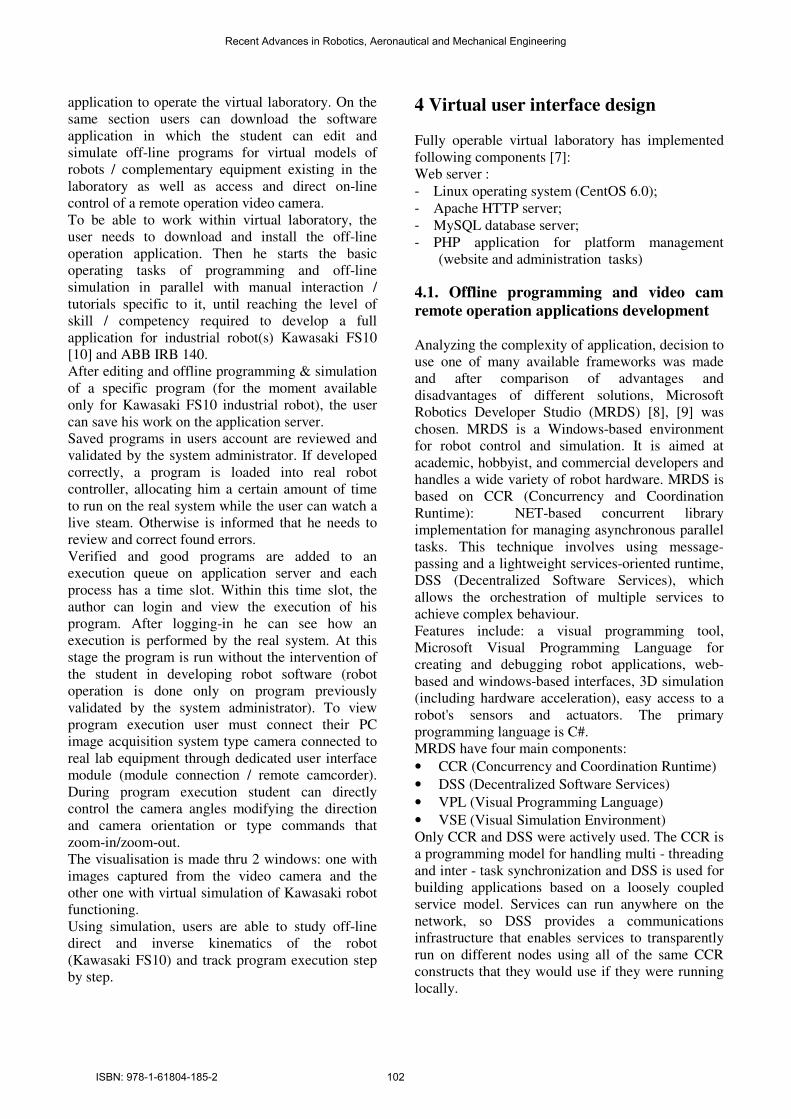
4 Virtual user interface design Fully operable virtual laboratory has implemented
following components [7]:
Web server :
- Linux operating system (CentOS 6.0);
- Apache HTTP server;
- MySQL database server;
- PHP application for platform management
(website and administration tasks)
4.1. Offline programming and video cam
remote operation applications development
Analyzing the complexity of application, decision to
use one of many available frameworks was made
and after comparison of advantages and
disadvantages of different solutions, Microsoft
Robotics Developer Studio (MRDS) [8], [9] was
chosen. MRDS is a Windows-based environment
for robot control and simulation. It is aimed at
academic, hobbyist, and commercial developers and
handles a wide variety of robot hardware. MRDS is
based on CCR (Concurrency and Coordination
Runtime): NET-based concurrent library
implementation for managing asynchronous parallel
tasks. This technique involves using message-
passing and a lightweight services-oriented runtime,
DSS (Decentralized Software Services), which
allows the orchestration of multiple services to
achieve complex behaviour.
Features include: a visual programming tool,
Microsoft Visual Programming Language for
creating and debugging robot applications, web-
based and windows-based interfaces, 3D simulation
(including hardware acceleration), easy access to a
robot's sensors and actuators. The primary
programming language is C#.
MRDS have four main components:
• CCR (Concurrency and Coordination Runtime)
• DSS (Decentralized Software Services)
• VPL (Visual Programming Language)
• VSE (Visual Simulation Environment)
Only CCR and DSS were actively used. The CCR is
a programming model for handling multi - threading
and inter - task synchronization and DSS is used for
building applications based on a loosely coupled
service model. Services can run anywhere on the
network, so DSS provides a communications
infrastructure that enables services to transparently
run on different nodes using all of the same CCR
constructs that they would use if they were running
locally.
Recent Advances in Robotics, Aeronautical and Mechanical Engineering
ISBN: 978-1-61804-185-2 102

In order to allow graphical representation of
industrial robots in MRDS, the virtual prototy
to be developed as an *.obj file type.
However, it is usually more convenient to use a
dedicated 3D solid modeller for developing IR’s
virtual prototype. For benefiting about the
advantages of using such kind of 3D solid modeller
is necessary to have the possibility to export the
virtual prototype and as well importing
file type. Because a direct export from
not possible, was need to be used an
software for converting prototype files.
To define the virtual prototype of a Kawasaki
FS10E industrial robot have been used all technical
information included in IR’s data sheet
as well as some specific dimensional measurements
made directly on the IR.
Figure 2. Kawasaki FS 10E robot characteristics
Using CATIA V5 we created first the prototype for
the robot (Fig 3a), than decompose it taking account
of partially IR’s assemblies as well as specific IR’s
major cinematic joint’s. Each partially assembly
defined as above has been processed for exporting it
from Catia, as *.wrl files extension (Virtual Reality
Modeling Language) (Fig 3b). Afterwards
files were imported in Blender (a free and open
source 3D computer graphics software product
for 3D modeling) and it were transformed in *.obj
files, in order to be compatible with MRDS software
platform (fig. 4a). After importing them into MRDS
each IR’s joint / IR’s degree of freedom
defined in MRDS accordingly a specific algorithm,
(fig. 4b).
a
Figure 3. Robot's overall virtual prototype: a) in Catia
V5, b) in Blender [7]
graphical representation of
in MRDS, the virtual prototype had
However, it is usually more convenient to use a
dedicated 3D solid modeller for developing IR’s
virtual prototype. For benefiting about the
such kind of 3D solid modeller
ve the possibility to export the
ing it as an *.obj
. Because a direct export from CATIA it is
an intermediate
files.
o define the virtual prototype of a Kawasaki
robot have been used all technical
information included in IR’s data sheet (Fig. 2) [10],
as well as some specific dimensional measurements
robot characteristics [10]
the prototype for
decompose it taking account
of partially IR’s assemblies as well as specific IR’s
major cinematic joint’s. Each partially assembly
processed for exporting it
extension (Virtual Reality
Afterwards *.wrl
free and open-
3D computer graphics software product used
transformed in *.obj
, in order to be compatible with MRDS software
After importing them into MRDS
IR’s joint / IR’s degree of freedom, has been
defined in MRDS accordingly a specific algorithm,
b
virtual prototype: a) in Catia
a Figure 4. Robot's partally assemblies virtual prototype: a)
*.obj files in Blender corresponding to each partially
assembly, b) IR’s joint definition
Figure 5. Robot's off-line programing and simulation.
User interface presenting specific
obtained by direct cinematic operation in
b
Figure 4. Robot's partally assemblies virtual prototype: a)
corresponding to each partially
joint definition in MRDS [7]
line programing and simulation.
User interface presenting specific robot’s configuration
obtained by direct cinematic operation in MRDS [7]
Recent Advances in Robotics, Aeronautical and Mechanical Engineering
ISBN: 978-1-61804-185-2 103

Figure 6. Robot's off-line programing and simulation.
User interface presenting specific robot’s configuration
obtained by reverse cinematic operation in
Figure 7. Video cam on-line remote operation. User
interface presenting facilities for left / right, up / down
and zoom-in / zoom-out direct cam control in
line programing and simulation.
User interface presenting specific robot’s configuration
obtained by reverse cinematic operation in MRDS [7]
line remote operation. User
interface presenting facilities for left / right, up / down
out direct cam control in MRDS [7]
4.2. Industrial robot’s
and video cam remote operation
System orientation used in MRDS
To define an articulated entity
together) we used a “Joint
degrees of freedom: three angular and three linear
and can be represented as a joint frame
the right - handed convention
joint frame are called the local axis, the normal axis,
and the binormal axis as shown above.
Figure 8. MRDS Joint Frame
Properties definition of a Joint Object
The joint properties define how the joint behaves
and how it attaches to the entities it joins. A joint
may contain a reference to a
“JointAngularPropertiesclass
more angular degrees of freedom. It may also
contain a reference to a
“JointLinearPropertiesclass
linear degrees of freedom. It must always contain a
two - element array of
references to specify how it attaches to each entity.
Functions and classes used for writing services that
interact with simulation engine extended base
classes defined in “RoboticsCommon.dll
“SimulationCommon.dll”.
below:
• “Vector2”, “Vector3”,
that contains number of floating
used to represent 2D and 3D o
• Quaternion - 3D rotations are represented by the
physics engine as quaternions;
• “Pose”: A Pose defines the position and
orientation of an entity within the simulation
environment. It consists of a
and a “Quaternionorientation
offline programming
and video cam remote operation in MRDS
orientation used in MRDS
To define an articulated entity (two entities joined
Joint” object. It has up to 6
of freedom: three angular and three linear
and can be represented as a joint frame that follows
vention. The three axes in a
joint frame are called the local axis, the normal axis,
and the binormal axis as shown above.
Figure 8. MRDS Joint Frame
Properties definition of a Joint Object
The joint properties define how the joint behaves
and how it attaches to the entities it joins. A joint
may contain a reference to a
JointAngularPropertiesclass” to unlock one or
more angular degrees of freedom. It may also
contain a reference to a
JointLinearPropertiesclass” to unlock one or more
linear degrees of freedom. It must always contain a
element array of “EntityJointConnector”
references to specify how it attaches to each entity.
Functions and classes used for writing services that
nteract with simulation engine extended base
RoboticsCommon.dll” and
The most used are listed
, “Vector4: are structures
that contains number of floating - point values
represent 2D and 3D objects;
3D rotations are represented by the
physics engine as quaternions;
defines the position and
orientation of an entity within the simulation
environment. It consists of a “Vector3position”
Quaternionorientation”.
Recent Advances in Robotics, Aeronautical and Mechanical Engineering
ISBN: 978-1-61804-185-2 104

• “Entity” is the base type for all entities in the
simulation environment and contains all of the
information common to both the simulation
engine and the physics engine;
• “EntityState”: This type contains information
about the entity such as its “Pose”, “Velocity”,
“Angular Velocity”, and “Name”
• “SimulationState” contains information about
the “Main Camera” and a list of all the entities
in the simulation environment.
• “Box Shape Properties” “Capsule Shape
Properties” hold state information about each
of the shape objects supported by the physics
engine.
• “BoxShape”, “CapsuleShape” are shapes
created from their associated shape properties.
They contain a reference to the actual physical
shape representation in the AGEIA physics
engine.
Simulation service
Building the simulation service implies
definition of certain global entities like: a floor,
a work scene, a model for the industrial robot.
The simulation engine communicates with a
view camera.
Conclusions:
This paper presents a synthesis of results obtained
in PHD thesis “Research on the development of
virtual user interfaces for applications in robotics
remote operation” showing the contribution made in
hardware-software platform of virtual laboratory for
industrial robots as well as the development process
for an advanced user interface elaborated in MRDS
for offline programming and simulation of industrial
robots by using direct/reverse cinematic and online
remote operation in association with a IP cam.
All developments has been achieved for a Kawasaki
FS 10 E industrial robot and are under development
for a second industrial robot (ABB IR 140 model)
5. Acknowledgements
The work has been funded by the Sectorial
Operational Program Human Resources
Development 2007-2013 of the Romanian Ministry
of Labor, Family and Social Protection through the
Financial Agreement POSDRU ID 5159.
References:
[1] Ravindra T, Luke H. H., Dr. Shi-Jer L. C. Ray
D, Controlling Robot Through Internet Using
Java, Journal of Industrial Technology Volume
20, Number 3 - June 2004
[2] Xiaoli Y., Qing C., Virtual Reality Tools for
Internet-Based Robotic Teleoperation, IEEE
International Symposium on Distributed
Simulation and Real-Time Applications DS-
RT’04, 2004
[3] F. A. Candelas Herías, C. A. Jara Bravo, F.
Torres Medina, Flexible virtual and remote
laboratory for teaching Robotics, Current
Developments in Technology-Assisted
Education 2006
[4] C.A. Jara, F.A. Candelas and F. Torres,
RobUaLab.ejs: a new tool for robotics e-
learning, REV2008 - www.rev-conference.org,
2008
[5] Dorin A. Nicolescu A. Popa S. - Software
architecture of the internet-based robotic
systems for teleoperation, Proceedings of the
International Conference on Manufacturing
Systems – ICMaS Vol. 4, November 5-6, 2009,
Bucharest, Romania, ISSN 1842-3183,
Romanian Academy Publishing House, 2009,
pag 91 – 98
[6] Popa S., Briceag C., Nicolescu A., Dorin A., -
“Software platform for virtual laboratory
operation by remote control of industrial
robots”, “The 21st DAAAM International
Symposium Intelligent Manufacturing &
Automation”, University of Zadar, Zadar,
Croatia, 20-23 October 2010, ISSN 1726-9687,
ISBN 978-3—901509-73-5, pag 1061-1062
[7] Popa S. “Cercetări privind dezvoltarea de
interfeţe utilizator virtuale pentru aplicaţii de
teleoperare în robotică”, PhD Thesis Scientific
Report 2, September 2011, Politehnica
University of Bucharest, Romania
[8] Professional Microsoft Robotics Developer
Studio. Trevor Taylor, Kyle Johns, ISBN-10:
0470141077, 2008
[9] Microsoft Robotics Developer Studio – MSDN
http://msdn.microsoft.com/en-
us/library/bb648760.aspx
[10] Kawasaki FS10E user manual, 2010
Recent Advances in Robotics, Aeronautical and Mechanical Engineering
ISBN: 978-1-61804-185-2 105