Embed Size (px)
Citation preview
Eggers 1
Virtual Testing based Type Approval Procedures for the Assessment of Pedestrian Protection developed within the EU-Project IMVITER Andre Eggers, Holger Schwedhelm, Oliver Zander Federal Highway Research Institute (BASt) Germany Roberto Cordero Izquierdo, Jesus Angel Garcia Polanco CIDAUT Foundation Spain John Paralikas, Konstantinos Georgoulias, George Chryssolouris Laboratory for Manufacturing Systems and Automation, University of Patras Greece Dominic Seibert Audi AG Germany Christophe Jacob ESI Group France Paper Number 13-0344 ABSTRACT For a number of EU regulatory acts Virtual Testing (VT) is already allowed for type approval (see Commission Regulation No. 371/2010 of 16 April 2010 amending the Framework Directive 2007/46/EC). However, only a very general procedure on how to apply VT for type approval is provided. Technical details for specific regulatory acts are not given yet. The main objective of the European project IMVITER (IMplementation of VIrtual TEsting in Safety Regulations) was to promote the implementation of VT in safety regulations. When proposing VT procedures the new regulation was taken into account, in particular, addressing open issues. Special attention was paid to pedestrian protection as pilot cases. A key aspect for VT implementation is to demonstrate that the employed simulation models are reliable. This paper describes how the Verification and Validation (V&V) method defined by the American Society of Mechanical Engineers was adapted for pedestrian protection VT based assessment. For the certification of headform impactors an extensive study was performed at two laboratories to assess the variability in calibration tests and equivalent results from a set of simulation models. Based on these results a methodology is defined for certification of headform impactor simulation models. A similar study was also performed with one vehicle in the type approval test setup. Its bonnet was highly instrumented and subjected to 45 impacts in five different positions at two laboratories in order to obtain an estimation of the variability in the physical tests. An equivalent
study was performed using stochastic simulation with a metamodel fed with observed variability in impact conditions of physical headforms. An estimation of the test method uncertainty was obtained and used in the definition of a validation corridor for simulation models. Validation metric and criteria were defined in cooperation with the ISO TC22 SC10 and SC12 WG4 "Virtual Testing". A complete validation procedure including different test setups, physical magnitudes and evaluation criteria is provided. A detailed procedural flowchart is developed for VT implementation in EC Regulation No 78/2009 based on a so called “Hybrid VT” approach, which combines real hardware based head impact tests and simulations. This detailed flowchart is shown and explained within this paper. Another important point within the virtual testing based procedures is the documentation of relevant information resulting from the verification and validation process of the numerical models used. For this purpose report templates were developed within the project. The proposed procedure fixes minimum V&V requirements for numerical models to be confidently used within the type-approval process. It is not intended to be a thorough guide on how to build such reliable models. Different modeling methodologies are therefore possible, according to particular OEM know-how. These requirements respond to a balance amongst the type-approval stakeholders interests. A cost-benefit analysis, which was also performed within the IMVITER project, supports this approach, showing the conditions in which VT implementation is beneficial. Based on the experience gained in the project and the background of the experts involved,
Eggers 2
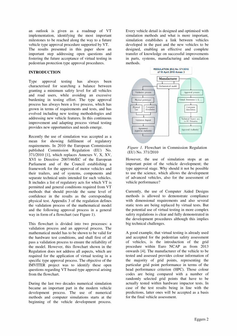
an outlook is given as a roadmap of VT implementation, identifying the most important milestones to be reached along the way to a future vehicle type approval procedure supported by VT. The results presented in this paper show an important step addressing open questions and fostering the future acceptance of virtual testing in pedestrian protection type approval procedures. INTRODUCTION Type approval testing has always been characterised for searching a balance between granting a minimum safety level for all vehicles and road users, while avoiding an excessive burdening in testing effort. The type approval process has always been a live process, which has grown in terms of requirements and tests, and has evolved including new testing methodologies and addressing new vehicle features. In this continuous improvement and adapting process virtual testing provides new opportunities and needs emerge. Recently the use of simulation was accepted as a mean for showing fulfilment of regulatory requirements. In 2010 the European Commission published Commission Regulation (EU) No. 371/2010 [1], which replaces Annexes V, X, XV, XVI to Directive 2007/46/EC of the European Parliament and of the Council establishing a framework for the approval of motor vehicles and their trailers, and of systems, components and separate technical units intended for such vehicles. It includes a list of regulatory acts for which VT is permitted and general conditions required from VT methods that should provide the same level of confidence in the results as the corresponding physical test. Appendix 3 of the regulation defines the validation process of the mathematical model and the following approval process in a general way in form of a flowchart (see Figure 1). This flowchart is divided into two processes: a validation process and an approval process. The mathematical model has to be shown to be valid for the hardware test conditions, and shall first of all pass a validation process to ensure the reliability of the model. However, this flowchart shown in the Regulation does not address all aspects, which are required for the application of virtual testing in a specific type approval process. The objective of the IMVITER project was to identify these open questions regarding VT based type approval arising from the flowchart. During the last two decades numerical simulation became an important part in the modern vehicle development process. The use of numerical methods and computer simulations starts at the beginning of the vehicle development process.
Every vehicle detail is designed and optimised with simulation methods and what is more important, simulation establishes a link between vehicles developed in the past and the new vehicles to be designed, enabling an effective and complete transfer of knowledge on successful improvements in parts, systems, manufacturing and simulation methods.
Figure 1. Flowchart in Commission Regulation (EU) No. 371/2010
However, the use of simulation stops at an important point of the vehicle development; the type approval stage. Why should it not be possible to use the science, which allows the development of advanced vehicles, also for the assessment of vehicle performance? Currently, the use of Computer Aided Designs methods is allowed to demonstrate compliance with dimensional requirements and also several static tests are being replaced by virtual tests. But the potential use of virtual testing in more complex safety regulations is clear and fully demonstrated in the development procedures although this implies big technical challenges. A good example, that virtual testing is already used and accepted for the pedestrian safety assessment of vehicles, is the introduction of the grid procedure within Euro NCAP as from 2013 onwards [4]. The manufacturer of the vehicle to be tested and assessed provides colour information of the majority of grid points, representing the particular grid point performance in terms of the head performance criterion (HPC). Those colour codes are being compared with a number of randomly selected grid points that have to be actually tested within hardware impactor tests. In case of the test results being in line with the predictions, latter ones will be accepted as a basis for the final vehicle assessment.
Eggers 3
During the last 15 years there have been many EC-funded projects dedicated to virtual testing and tools. The project IMPACT was looking into the very specific topic of failure prediction by numerical simulation. In ADVANCE, some software tools for automatic evaluation of the quality of simulations and guidelines for optimisation of the simulations were developed. The projects VITES already had a similar objective, namely to define the virtual testing process for crash safety applications. In APROSYS this topic was continued resulting in a vision on virtual testing in regulations that was developed in open communication with the stakeholders. However, the final detailed application of the procedure in a level of detail needed for direct implementation in a regulatory context was not achieved. This is the point where the project IMVITER should continue this effort and actually apply the research findings to pilot case regulations as cases e.g. in the area of pedestrian protection regulations. Within the IMVITER project the verification and validation methodology was applied to four pilot cases. Each case had some specific or particular aims:
• Pilot case 1: pedestrian head impact. Is a good example of a repetitive test, meaning that according to the directive requirements 18 impacts have to be conducted on the vehicle hood. A reduction of impact tests was addressed, and the verification and validation methodology that was developed in this pilot case, is extendible to any other regulatory act based on repetitive tests. • Pilot case 2: seat belt anchorage strength: in this case the methodology was focused on cases where type approval extension is suitable, thus criteria to assess when small modifications do not invalidate an already validated simulation model • Pilot case 3: towing hook: this case provided data to evaluate simulation and modelling differences among codes, and was be the basis to define code verification requirements • Pilot case 4: this case was selected as a continuation of APROSYS work, addressing pedestrian lower leg impact. In particular it focused on advanced impactor certification requirements.
Within this paper the focus will be on pilot case 1, pedestrian head impact. The work presented in this paper should provide indications where Virtual Testing is already used within the type approval process today, where it can go in the future, and how such objectives can be achieved.
VERIFICATION AND VALIDATION (V&V) APPROACH What is V&V? In order to incorporate simulation predictions in the vehicles’ type approval scheme, namely VT, there is a need for a robust and reliable way is needed to evaluate how good a model approximates its real counterpart. The key point is an appropriate metric to quantify the correlation. A solution to this issue was proposed by the American Society of Mechanical Engineers (ASME), that created a reference guide [2] in which the “Verification and Validation” methodology is presented. Basically two main activities are concerned:
• Verification: The process of determining that a computational model accurately represents the underlying mathematical model and its solution • Validation: The process of determining the degree to which a model is an accurate representation of the real world from the perspective of the intended uses of the model
In the following the focus is on validation. Basically this methodology is based in gathering data from the real system and comparing it to the results from the simulation model. How was V&V considered in IMVITER? If there were no time, neither cost limitations, the V&V methodology could be directly applied for the purpose of introducing VT as part of the vehicles type approval regulatory acts. A simplification of the V&V method has to be done in order to respect the automotive industry time-to-market and cost requirements, otherwise the automotive industry would continue using physical tests. Based on this two phases were deployed. First, the interpretation and application of the ideal V&V methodology to the three IMVITER pilot cases. Secondly, simplifications in terms of number of tests and simulations, in order to define a less costly and time consuming approach. How was V&V developed in the pedestrian protection case? A complete description of simulation models and experimental tests emerged directly from the application of the V&V approach to the pedestrian protection pilot case. For the description of the set of calculations and corresponding experimental tests, a validation plan was described including:
• Which experimental tests can better reproduce and measure the physical events of interest?
Eggers 4
• Which simulation models were to be developed to reproduce real physical events?
• How the RT and corresponding VT results were to be compared (variables to be measured, validation metrics and acceptance criteria to be applied)?
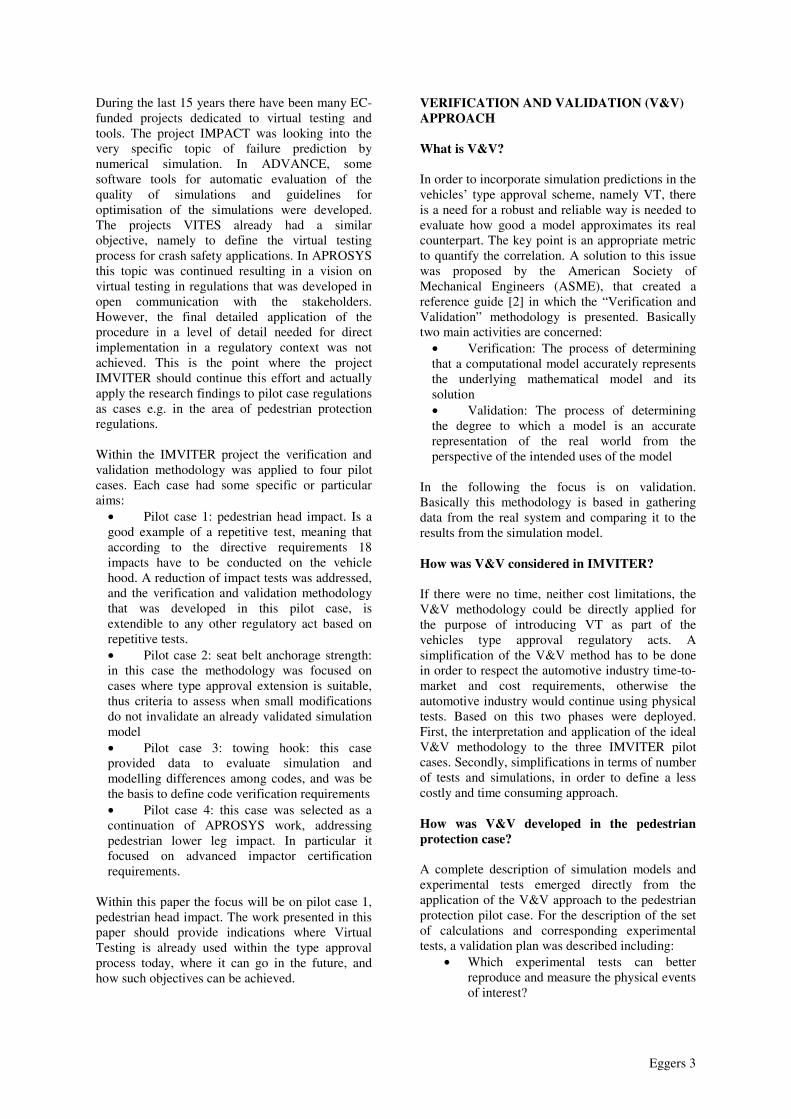
A building block approach was followed to define validation activities, as shown in Figure 2.
Whole test
Subsystem case
Unit probl
Imp
acto
r te
sts
ho
od
test
Contact phenomena
Material modelsForming stresses
Boundary conditions
Validation Hierarchy
Figure 2. Decomposition of the full scale head impact case into three complexity levels, following a building blocks approach
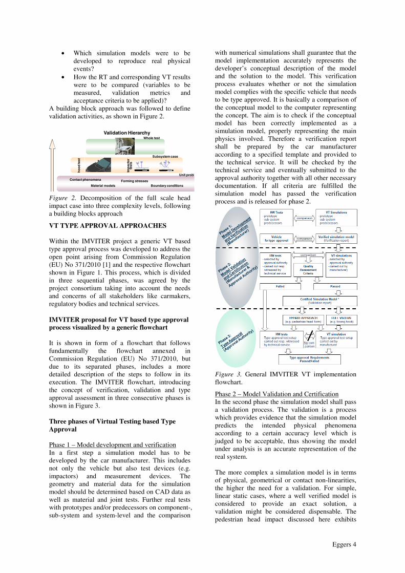
VT TYPE APPROVAL APPROACHES Within the IMVITER project a generic VT based type approval process was developed to address the open point arising from Commission Regulation (EU) No 371/2010 [1] and the respective flowchart shown in Figure 1. This process, which is divided in three sequential phases, was agreed by the project consortium taking into account the needs and concerns of all stakeholders like carmakers, regulatory bodies and technical services. IMVITER proposal for VT based type approval process visualized by a generic flowchart It is shown in form of a flowchart that follows fundamentally the flowchart annexed in Commission Regulation (EU) No 371/2010, but due to its separated phases, includes a more detailed description of the steps to follow in its execution. The IMVITER flowchart, introducing the concept of verification, validation and type approval assessment in three consecutive phases is shown in Figure 3. Three phases of Virtual Testing based Type Approval Phase 1 – Model development and verification In a first step a simulation model has to be developed by the car manufacturer. This includes not only the vehicle but also test devices (e.g. impactors) and measurement devices. The geometry and material data for the simulation model should be determined based on CAD data as well as material and joint tests. Further real tests with prototypes and/or predecessors on component-, sub-system and system-level and the comparison
with numerical simulations shall guarantee that the model implementation accurately represents the developer’s conceptual description of the model and the solution to the model. This verification process evaluates whether or not the simulation model complies with the specific vehicle that needs to be type approved. It is basically a comparison of the conceptual model to the computer representing the concept. The aim is to check if the conceptual model has been correctly implemented as a simulation model, properly representing the main physics involved. Therefore a verification report shall be prepared by the car manufacturer according to a specified template and provided to the technical service. It will be checked by the technical service and eventually submitted to the approval authority together with all other necessary documentation. If all criteria are fulfilled the simulation model has passed the verification process and is released for phase 2.
Figure 3. General IMVITER VT implementation flowchart.
Phase 2 – Model Validation and Certification In the second phase the simulation model shall pass a validation process. The validation is a process which provides evidence that the simulation model predicts the intended physical phenomena according to a certain accuracy level which is judged to be acceptable, thus showing the model under analysis is an accurate representation of the real system. The more complex a simulation model is in terms of physical, geometrical or contact non-linearities, the higher the need for a validation. For simple, linear static cases, where a well verified model is considered to provide an exact solution, a validation might be considered dispensable. The pedestrian head impact discussed here exhibits
Eggers 5
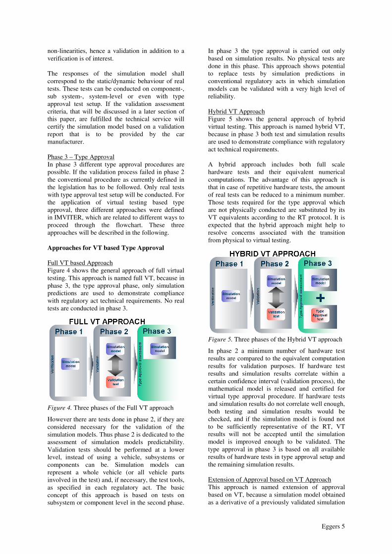
non-linearities, hence a validation in addition to a verification is of interest. The responses of the simulation model shall correspond to the static/dynamic behaviour of real tests. These tests can be conducted on component-, sub system-, system-level or even with type approval test setup. If the validation assessment criteria, that will be discussed in a later section of this paper, are fulfilled the technical service will certify the simulation model based on a validation report that is to be provided by the car manufacturer. Phase 3 – Type Approval In phase 3 different type approval procedures are possible. If the validation process failed in phase 2 the conventional procedure as currently defined in the legislation has to be followed. Only real tests with type approval test setup will be conducted. For the application of virtual testing based type approval, three different approaches were defined in IMVITER, which are related to different ways to proceed through the flowchart. These three approaches will be described in the following. Approaches for VT based Type Approval Full VT based Approach Figure 4 shows the general approach of full virtual testing. This approach is named full VT, because in phase 3, the type approval phase, only simulation predictions are used to demonstrate compliance with regulatory act technical requirements. No real tests are conducted in phase 3.
Figure 4. Three phases of the Full VT approach
However there are tests done in phase 2, if they are considered necessary for the validation of the simulation models. Thus phase 2 is dedicated to the assessment of simulation models predictability. Validation tests should be performed at a lower level, instead of using a vehicle, subsystems or components can be. Simulation models can represent a whole vehicle (or all vehicle parts involved in the test) and, if necessary, the test tools, as specified in each regulatory act. The basic concept of this approach is based on tests on subsystem or component level in the second phase.
In phase 3 the type approval is carried out only based on simulation results. No physical tests are done in this phase. This approach shows potential to replace tests by simulation predictions in conventional regulatory acts in which simulation models can be validated with a very high level of reliability. Hybrid VT Approach Figure 5 shows the general approach of hybrid virtual testing. This approach is named hybrid VT, because in phase 3 both test and simulation results are used to demonstrate compliance with regulatory act technical requirements. A hybrid approach includes both full scale hardware tests and their equivalent numerical computations. The advantage of this approach is that in case of repetitive hardware tests, the amount of real tests can be reduced to a minimum number. Those tests required for the type approval which are not physically conducted are substituted by its VT equivalents according to the RT protocol. It is expected that the hybrid approach might help to resolve concerns associated with the transition from physical to virtual testing.
Figure 5. Three phases of the Hybrid VT approach
In phase 2 a minimum number of hardware test results are compared to the equivalent computation results for validation purposes. If hardware test results and simulation results correlate within a certain confidence interval (validation process), the mathematical model is released and certified for virtual type approval procedure. If hardware tests and simulation results do not correlate well enough, both testing and simulation results would be checked, and if the simulation model is found not to be sufficiently representative of the RT, VT results will not be accepted until the simulation model is improved enough to be validated. The type approval in phase 3 is based on all available results of hardware tests in type approval setup and the remaining simulation results. Extension of Approval based on VT Approach This approach is named extension of approval based on VT, because a simulation model obtained as a derivative of a previously validated simulation
Eggers 6
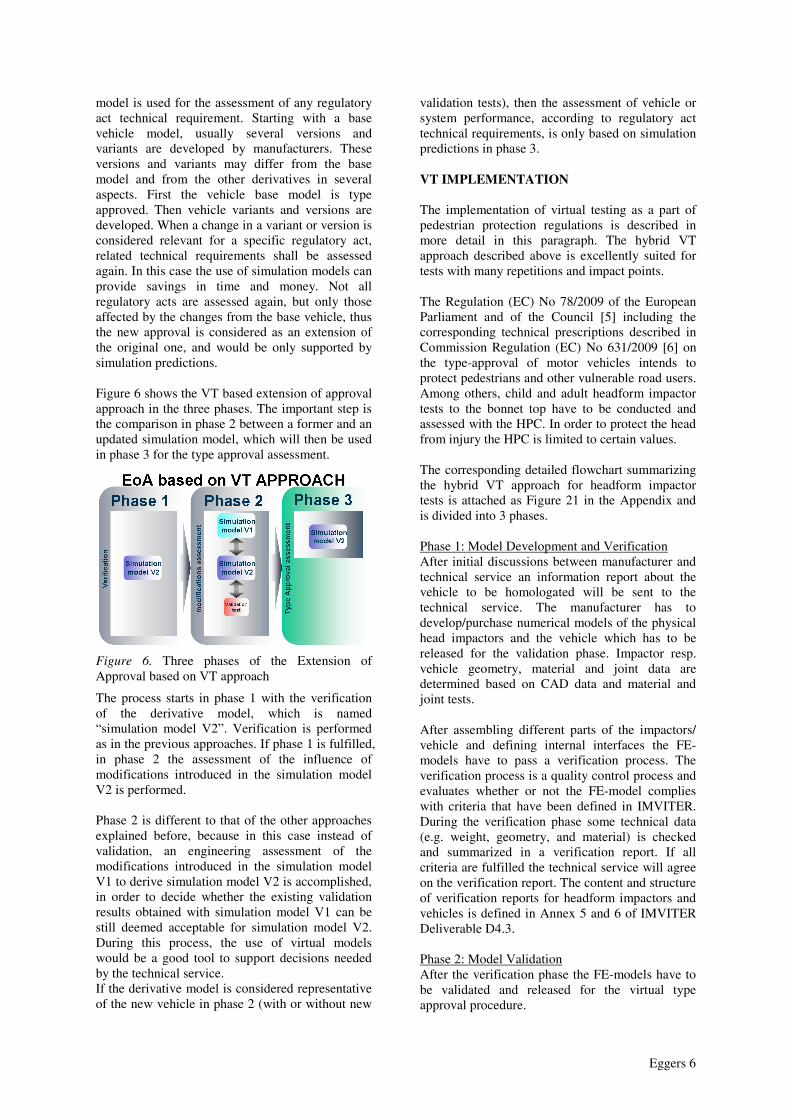
model is used for the assessment of any regulatory act technical requirement. Starting with a base vehicle model, usually several versions and variants are developed by manufacturers. These versions and variants may differ from the base model and from the other derivatives in several aspects. First the vehicle base model is type approved. Then vehicle variants and versions are developed. When a change in a variant or version is considered relevant for a specific regulatory act, related technical requirements shall be assessed again. In this case the use of simulation models can provide savings in time and money. Not all regulatory acts are assessed again, but only those affected by the changes from the base vehicle, thus the new approval is considered as an extension of the original one, and would be only supported by simulation predictions. Figure 6 shows the VT based extension of approval approach in the three phases. The important step is the comparison in phase 2 between a former and an updated simulation model, which will then be used in phase 3 for the type approval assessment.
Figure 6. Three phases of the Extension of Approval based on VT approach
The process starts in phase 1 with the verification of the derivative model, which is named “simulation model V2”. Verification is performed as in the previous approaches. If phase 1 is fulfilled, in phase 2 the assessment of the influence of modifications introduced in the simulation model V2 is performed. Phase 2 is different to that of the other approaches explained before, because in this case instead of validation, an engineering assessment of the modifications introduced in the simulation model V1 to derive simulation model V2 is accomplished, in order to decide whether the existing validation results obtained with simulation model V1 can be still deemed acceptable for simulation model V2. During this process, the use of virtual models would be a good tool to support decisions needed by the technical service. If the derivative model is considered representative of the new vehicle in phase 2 (with or without new
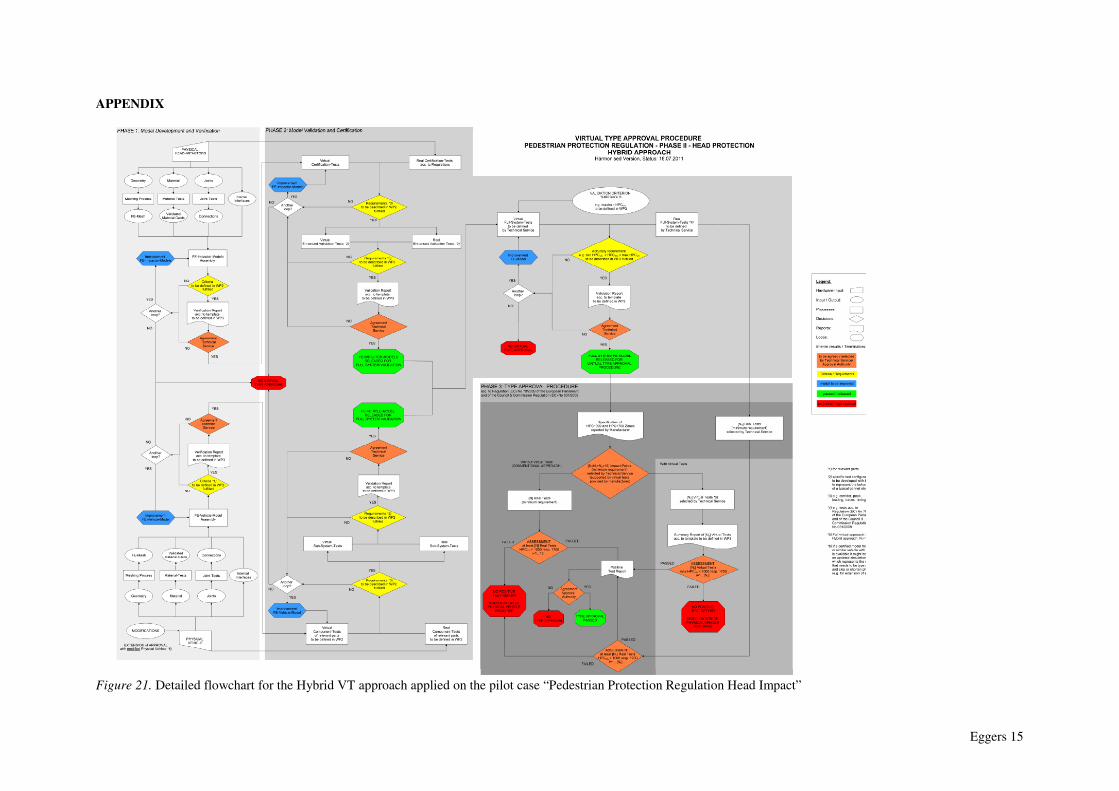
validation tests), then the assessment of vehicle or system performance, according to regulatory act technical requirements, is only based on simulation predictions in phase 3. VT IMPLEMENTATION The implementation of virtual testing as a part of pedestrian protection regulations is described in more detail in this paragraph. The hybrid VT approach described above is excellently suited for tests with many repetitions and impact points. The Regulation (EC) No 78/2009 of the European Parliament and of the Council [5] including the corresponding technical prescriptions described in Commission Regulation (EC) No 631/2009 [6] on the type-approval of motor vehicles intends to protect pedestrians and other vulnerable road users. Among others, child and adult headform impactor tests to the bonnet top have to be conducted and assessed with the HPC. In order to protect the head from injury the HPC is limited to certain values. The corresponding detailed flowchart summarizing the hybrid VT approach for headform impactor tests is attached as Figure 21 in the Appendix and is divided into 3 phases. Phase 1: Model Development and Verification After initial discussions between manufacturer and technical service an information report about the vehicle to be homologated will be sent to the technical service. The manufacturer has to develop/purchase numerical models of the physical head impactors and the vehicle which has to be released for the validation phase. Impactor resp. vehicle geometry, material and joint data are determined based on CAD data and material and joint tests. After assembling different parts of the impactors/ vehicle and defining internal interfaces the FE-models have to pass a verification process. The verification process is a quality control process and evaluates whether or not the FE-model complies with criteria that have been defined in IMVITER. During the verification phase some technical data (e.g. weight, geometry, and material) is checked and summarized in a verification report. If all criteria are fulfilled the technical service will agree on the verification report. The content and structure of verification reports for headform impactors and vehicles is defined in Annex 5 and 6 of IMVITER Deliverable D4.3. Phase 2: Model Validation After the verification phase the FE-models have to be validated and released for the virtual type approval procedure.

Eggers 7
The validation process is a predictability assurance process and provides evidence that the FE-models accomplish its intended requirements. The responses of the impactor models have to correspond to the dynamic behaviour of the physical head impactors in certification tests and enhanced validation tests (test setups in later sections of this paper). If all requirements are fulfilled, documented and provided by the car manufacturer, the technical service will agree on the validation report. The physical vehicle for which the type approval is requested has to be also validated and released in the same way like previously described for the head impactors. For validation purposes component- and subsystem-tests have to be conducted with relevant parts. If requirements are not fulfilled, the FE-model has to be improved. After impactor models and the vehicle model are validated on its own they are released for full-system validation tests. The manufacturer can provide, on a voluntary basis, information to the technical service based on the simulation model predictions, supporting the selection of the worst cases. Based on this the technical service and the manufacturer can specify the validation plan in a meeting. The agreed validation plan is then documented by the manufacturer and sent to the technical service. The technical service witnesses at the manufacturer or a third party facilities the results of the simulation prediction in the validation cases. For pedestrian protection a number [N1] of full system hardware tests according to (EC) No 631/2009 has to be conducted and compared to corresponding virtual tests. In order to avoid a decrease in current safety level the scatter of real test results has to be taken into account determining a validation criterion threshold (max/min HICVTi) which has been investigated in IMVITER. The full system FE-model is released for the virtual type approval procedure if an accuracy requirement is fulfilled. The FE-model is certified by the technical service who will agree on the validation report prepared by the car manufacturer. If the accuracy requirement is not met the full system FE-model needs to be further improved. In case of a second approval requested due to significant modifications of the physical vehicle the
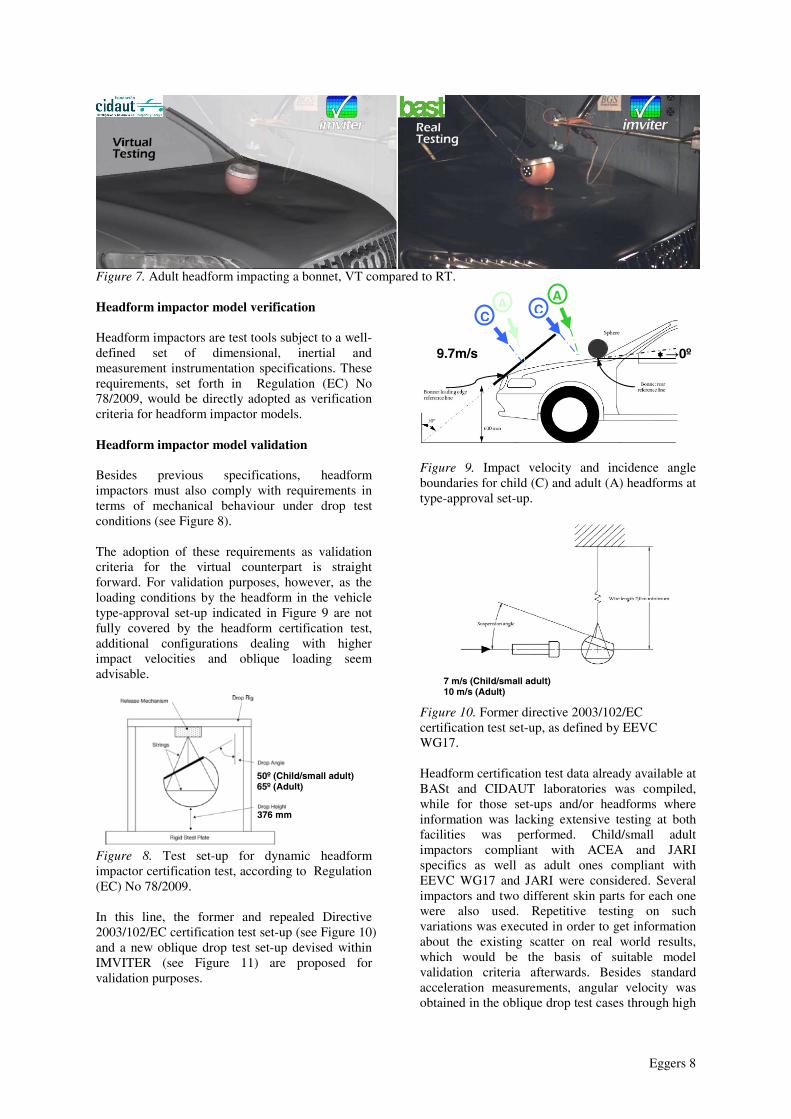
numerical model of the vehicle has to be updated with these modifications and has to pass the verification and validation process as described above again. Phase 3: Type approval In the type approval phase both HPC 1000 and HPC 1700 zones as described in Regulation (EC) No 78/2009 for phase 2 have to be reported by the car manufacturer and at least 18 impact points [N=N1+N2] are selected by the technical service. The car manufacturer conducts numerical simulations for these selected impact points. If selected impact points have been already tested in phase 2 up to [N1] real test results are available for assessment. So the car manufacturer has the opportunity to replace a number [N2] of real tests by virtual tests. All virtual test results shall be summarized in a report. If the maximum HPC exceeds a value of 1000 resp. 1700, the assessment cannot be positive and some modifications of the vehicle are required. In any case the vehicle manufacturer resp. the approval authority can decide that a virtual type approval is not possible and all tests have to be conducted physically according to Regulation (EC) No 78/2009 of the European Parliament and of the Council and Commission Regulation (EC) No 631/2009. Figure 7 shows a comparison between virtual and real testing impacting the bonnet of a large SUV. Figure 7 shows a comparison between virtual and real testing in which a headform impactor is hitting the bonnet of a vehicle. VERIFICATION AND VALIDATION METRICS AND CRITERIA Within the vehicle type-approval scenario, “a virtual testing method should provide for the same level of confidence in the results as a physical test. Therefore, it is appropriate to lay down relevant conditions to ensure that proper validation of the mathematical models is conducted” [1]. IMVITER has tackled the establishment of such conditions for the implementation of virtual testing in the European Regulation on pedestrian (head) protection, from a scientific point of view and accounting for the expertise of representatives from all the involved stakeholders.
Eggers 8
Figure 7. Adult headform impacting a bonnet, VT compared to RT. Headform impactor model verification Headform impactors are test tools subject to a well-defined set of dimensional, inertial and measurement instrumentation specifications. These requirements, set forth in Regulation (EC) No 78/2009, would be directly adopted as verification criteria for headform impactor models. Headform impactor model validation Besides previous specifications, headform impactors must also comply with requirements in terms of mechanical behaviour under drop test conditions (see Figure 8). The adoption of these requirements as validation criteria for the virtual counterpart is straight forward. For validation purposes, however, as the loading conditions by the headform in the vehicle type-approval set-up indicated in Figure 9 are not fully covered by the headform certification test, additional configurations dealing with higher impact velocities and oblique loading seem advisable.
Figure 8. Test set-up for dynamic headform impactor certification test, according to Regulation (EC) No 78/2009. In this line, the former and repealed Directive 2003/102/EC certification test set-up (see Figure 10) and a new oblique drop test set-up devised within IMVITER (see Figure 11) are proposed for validation purposes.
Figure 9. Impact velocity and incidence angle boundaries for child (C) and adult (A) headforms at type-approval set-up.
Figure 10. Former directive 2003/102/EC certification test set-up, as defined by EEVC WG17. Headform certification test data already available at BASt and CIDAUT laboratories was compiled, while for those set-ups and/or headforms where information was lacking extensive testing at both facilities was performed. Child/small adult impactors compliant with ACEA and JARI specifics as well as adult ones compliant with EEVC WG17 and JARI were considered. Several impactors and two different skin parts for each one were also used. Repetitive testing on such variations was executed in order to get information about the existing scatter on real world results, which would be the basis of suitable model validation criteria afterwards. Besides standard acceleration measurements, angular velocity was obtained in the oblique drop test cases through high
25-90º
7 m/s (Child/small adult) 10 m/s (Adult)
376 mm
50º (Child/small adult) 65º (Adult)
→0º
C C A A
9.7m/s
Eggers 9
speed video recording and subsequent tracking analysis or dedicated sensors, as rotational movement is a relevant physical magnitude for those impacts.
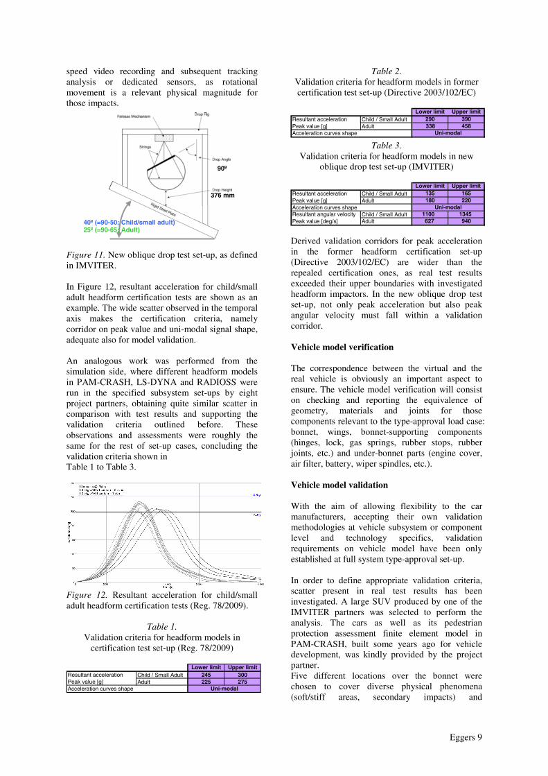
Figure 11. New oblique drop test set-up, as defined in IMVITER. In Figure 12, resultant acceleration for child/small adult headform certification tests are shown as an example. The wide scatter observed in the temporal axis makes the certification criteria, namely corridor on peak value and uni-modal signal shape, adequate also for model validation. An analogous work was performed from the simulation side, where different headform models in PAM-CRASH, LS-DYNA and RADIOSS were run in the specified subsystem set-ups by eight project partners, obtaining quite similar scatter in comparison with test results and supporting the validation criteria outlined before. These observations and assessments were roughly the same for the rest of set-up cases, concluding the validation criteria shown in Table 1 to Table 3.
Figure 12. Resultant acceleration for child/small adult headform certification tests (Reg. 78/2009).
Table 1.
Validation criteria for headform models in certification test set-up (Reg. 78/2009)
Table 2. Validation criteria for headform models in former certification test set-up (Directive 2003/102/EC)
Table 3. Validation criteria for headform models in new
oblique drop test set-up (IMVITER) Derived validation corridors for peak acceleration in the former headform certification set-up (Directive 2003/102/EC) are wider than the repealed certification ones, as real test results exceeded their upper boundaries with investigated headform impactors. In the new oblique drop test set-up, not only peak acceleration but also peak angular velocity must fall within a validation corridor. Vehicle model verification The correspondence between the virtual and the real vehicle is obviously an important aspect to ensure. The vehicle model verification will consist on checking and reporting the equivalence of geometry, materials and joints for those components relevant to the type-approval load case: bonnet, wings, bonnet-supporting components (hinges, lock, gas springs, rubber stops, rubber joints, etc.) and under-bonnet parts (engine cover, air filter, battery, wiper spindles, etc.). Vehicle model validation With the aim of allowing flexibility to the car manufacturers, accepting their own validation methodologies at vehicle subsystem or component level and technology specifics, validation requirements on vehicle model have been only established at full system type-approval set-up. In order to define appropriate validation criteria, scatter present in real test results has been investigated. A large SUV produced by one of the IMVITER partners was selected to perform the analysis. The cars as well as its pedestrian protection assessment finite element model in PAM-CRASH, built some years ago for vehicle development, was kindly provided by the project partner. Five different locations over the bonnet were chosen to cover diverse physical phenomena (soft/stiff areas, secondary impacts) and
Lower limit Upper limitChild / Small Adult 245 300Adult 225 275
Acceleration curves shape Uni-modal
Resultant accelerationPeak value [g]
90º
40º (=90-50; Child/small adult) 25º (=90-65; Adult)
376 mm
Lower limit Upper limitChild / Small Adult 290 390 Adult 338 458
Acceleration curves shape Uni-modal
Resultant accelerationPeak value [g]
Lower limit Upper limitChild / Small Adult 135 165 Adult 180 220
Child / Small Adult 1100 1345Adult 627 940
Uni-modalResultant angular velocityPeak value [deg/s]
Resultant accelerationPeak value [g]Acceleration curves shape
Eggers 10
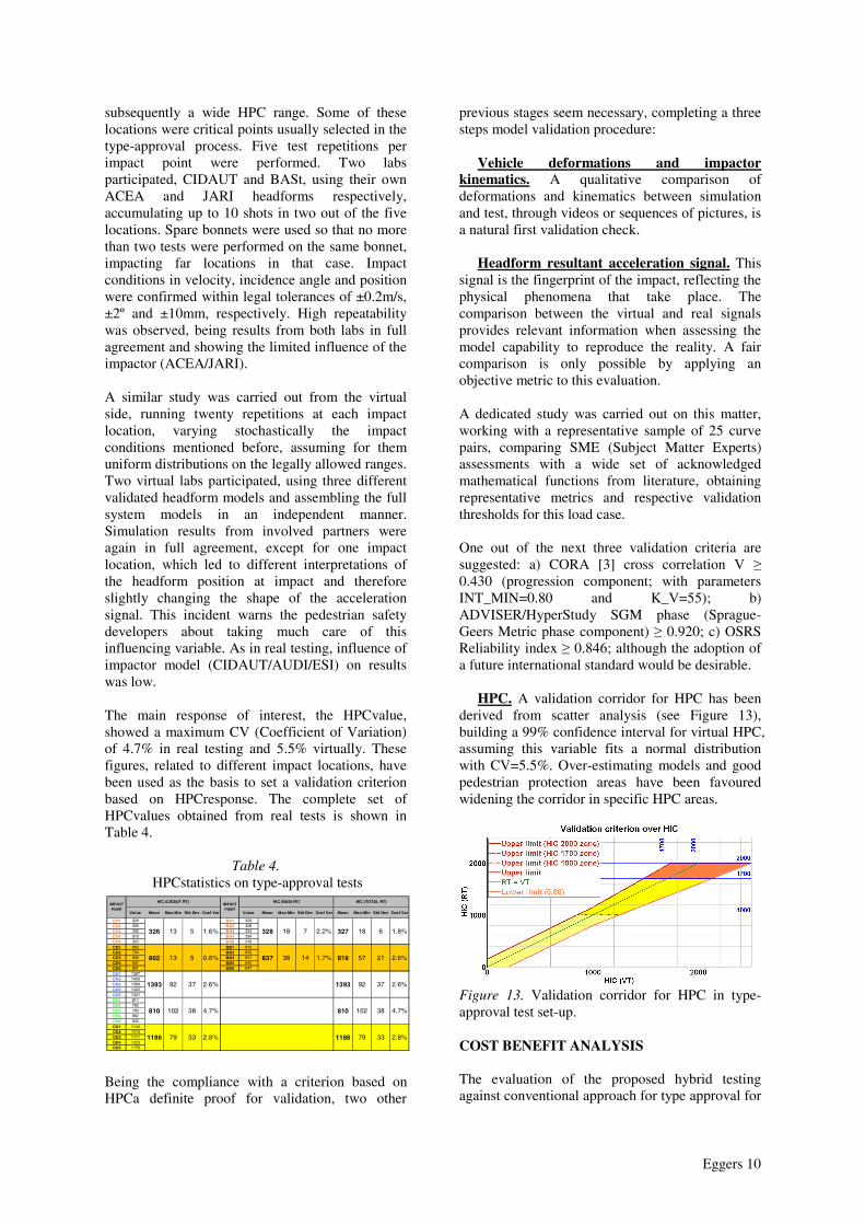
subsequently a wide HPC range. Some of these locations were critical points usually selected in the type-approval process. Five test repetitions per impact point were performed. Two labs participated, CIDAUT and BASt, using their own ACEA and JARI headforms respectively, accumulating up to 10 shots in two out of the five locations. Spare bonnets were used so that no more than two tests were performed on the same bonnet, impacting far locations in that case. Impact conditions in velocity, incidence angle and position were confirmed within legal tolerances of ±0.2m/s, ±2º and ±10mm, respectively. High repeatability was observed, being results from both labs in full agreement and showing the limited influence of the impactor (ACEA/JARI). A similar study was carried out from the virtual side, running twenty repetitions at each impact location, varying stochastically the impact conditions mentioned before, assuming for them uniform distributions on the legally allowed ranges. Two virtual labs participated, using three different validated headform models and assembling the full system models in an independent manner. Simulation results from involved partners were again in full agreement, except for one impact location, which led to different interpretations of the headform position at impact and therefore slightly changing the shape of the acceleration signal. This incident warns the pedestrian safety developers about taking much care of this influencing variable. As in real testing, influence of impactor model (CIDAUT/AUDI/ESI) on results was low. The main response of interest, the HPCvalue, showed a maximum CV (Coefficient of Variation) of 4.7% in real testing and 5.5% virtually. These figures, related to different impact locations, have been used as the basis to set a validation criterion based on HPCresponse. The complete set of HPCvalues obtained from real tests is shown in Table 4.
Table 4. HPCstatistics on type-approval tests
Value Mean Max-Min Std Dev Coef Var Value Mean Max-Min Std Dev Coef Var Mean Max-Min Std Dev Coef Var
C1I1 329 B1I1 329C1I2 326 B1I2 328C1I3 332 B1I3 334C1I4 319 B1I4 334C1I5 323 B1I5 316C2I1 802 B2I1 815C2I2 794 B2I2 832C2I3 806 B2I3 851C2I4 807 B2I4 840C2I5 801 B2I5 847C4I1 1387C4I2 1433C4I3 1380C4I4 1422C4I5 1341C5I1 817C5I2 790C5I3 760C5I4 862C5I5 822C6I1 1144C6I2 1215C6I3 1171C6I4 1223C6I5 1176
1393 37 2.6%
18
57
92
819 21 2.6%
HIC (TOTAL RT)
327 6 1.8%2.2%
837 14
18
36 1.7%
810 38 4.7%
1186 33
102
79 2.8%
810 38 4.7%
1186 33 2.8%
102
79
802 5 0.6%
1393 37 2.6%
13
92
HIC (BASt RT)
328
HIC (CIDAUT RT)IMPACTPOINT
326 5 1.6% 713
IMPACTPOINT
Being the compliance with a criterion based on HPCa definite proof for validation, two other
previous stages seem necessary, completing a three steps model validation procedure: Vehicle deformations and impactor kinematics. A qualitative comparison of deformations and kinematics between simulation and test, through videos or sequences of pictures, is a natural first validation check. Headform resultant acceleration signal. This signal is the fingerprint of the impact, reflecting the physical phenomena that take place. The comparison between the virtual and real signals provides relevant information when assessing the model capability to reproduce the reality. A fair comparison is only possible by applying an objective metric to this evaluation. A dedicated study was carried out on this matter, working with a representative sample of 25 curve pairs, comparing SME (Subject Matter Experts) assessments with a wide set of acknowledged mathematical functions from literature, obtaining representative metrics and respective validation thresholds for this load case. One out of the next three validation criteria are suggested: a) CORA [3] cross correlation V ≥ 0.430 (progression component; with parameters INT_MIN=0.80 and K_V=55); b) ADVISER/HyperStudy SGM phase (Sprague-Geers Metric phase component) ≥ 0.920; c) OSRS Reliability index ≥ 0.846; although the adoption of a future international standard would be desirable. HPC. A validation corridor for HPC has been derived from scatter analysis (see Figure 13), building a 99% confidence interval for virtual HPC, assuming this variable fits a normal distribution with CV=5.5%. Over-estimating models and good pedestrian protection areas have been favoured widening the corridor in specific HPC areas.
Figure 13. Validation corridor for HPC in type-approval test set-up. COST BENEFIT ANALYSIS The evaluation of the proposed hybrid testing against conventional approach for type approval for
Eggers 11
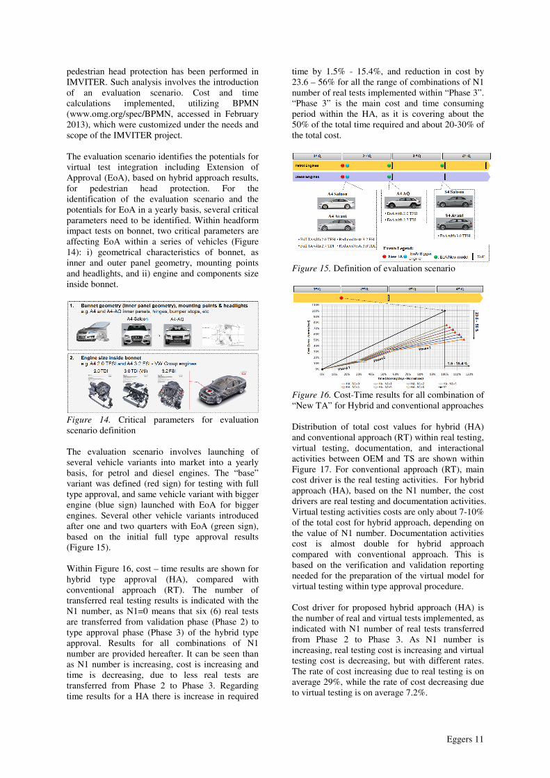
pedestrian head protection has been performed in IMVITER. Such analysis involves the introduction of an evaluation scenario. Cost and time calculations implemented, utilizing BPMN (www.omg.org/spec/BPMN, accessed in February 2013), which were customized under the needs and scope of the IMVITER project. The evaluation scenario identifies the potentials for virtual test integration including Extension of Approval (EoA), based on hybrid approach results, for pedestrian head protection. For the identification of the evaluation scenario and the potentials for EoA in a yearly basis, several critical parameters need to be identified. Within headform impact tests on bonnet, two critical parameters are affecting EoA within a series of vehicles (Figure 14): i) geometrical characteristics of bonnet, as inner and outer panel geometry, mounting points and headlights, and ii) engine and components size inside bonnet.
Figure 14. Critical parameters for evaluation scenario definition The evaluation scenario involves launching of several vehicle variants into market into a yearly basis, for petrol and diesel engines. The “base” variant was defined (red sign) for testing with full type approval, and same vehicle variant with bigger engine (blue sign) launched with EoA for bigger engines. Several other vehicle variants introduced after one and two quarters with EoA (green sign), based on the initial full type approval results (Figure 15). Within Figure 16, cost – time results are shown for hybrid type approval (HA), compared with conventional approach (RT). The number of transferred real testing results is indicated with the N1 number, as N1=0 means that six (6) real tests are transferred from validation phase (Phase 2) to type approval phase (Phase 3) of the hybrid type approval. Results for all combinations of N1 number are provided hereafter. It can be seen than as N1 number is increasing, cost is increasing and time is decreasing, due to less real tests are transferred from Phase 2 to Phase 3. Regarding time results for a HA there is increase in required
time by 1.5% - 15.4%, and reduction in cost by 23.6 – 56% for all the range of combinations of N1 number of real tests implemented within “Phase 3”. “Phase 3” is the main cost and time consuming period within the HA, as it is covering about the 50% of the total time required and about 20-30% of the total cost.
Figure 15. Definition of evaluation scenario
Figure 16. Cost-Time results for all combination of “New TA” for Hybrid and conventional approaches Distribution of total cost values for hybrid (HA) and conventional approach (RT) within real testing, virtual testing, documentation, and interactional activities between OEM and TS are shown within Figure 17. For conventional approach (RT), main cost driver is the real testing activities. For hybrid approach (HA), based on the N1 number, the cost drivers are real testing and documentation activities. Virtual testing activities costs are only about 7-10% of the total cost for hybrid approach, depending on the value of N1 number. Documentation activities cost is almost double for hybrid approach compared with conventional approach. This is based on the verification and validation reporting needed for the preparation of the virtual model for virtual testing within type approval procedure. Cost driver for proposed hybrid approach (HA) is the number of real and virtual tests implemented, as indicated with N1 number of real tests transferred from Phase 2 to Phase 3. As N1 number is increasing, real testing cost is increasing and virtual testing cost is decreasing, but with different rates. The rate of cost increasing due to real testing is on average 29%, while the rate of cost decreasing due to virtual testing is on average 7.2%.
Eggers 12
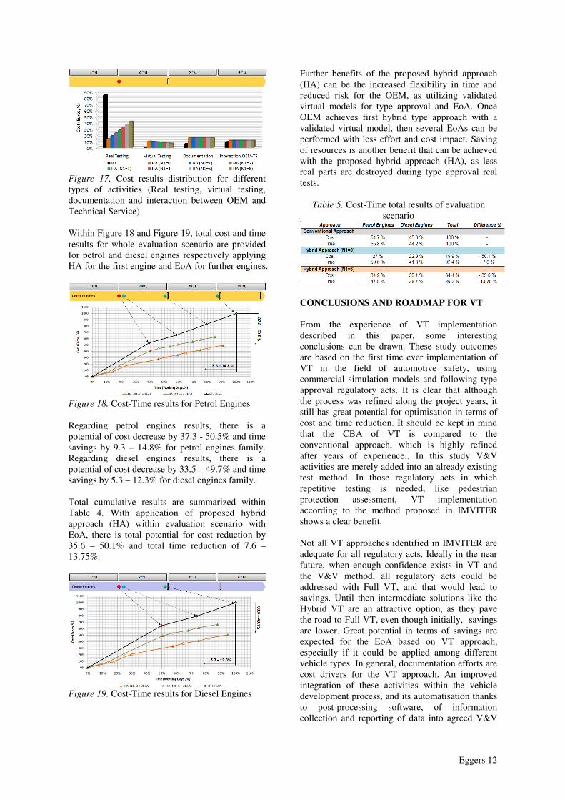
Figure 17. Cost results distribution for different types of activities (Real testing, virtual testing, documentation and interaction between OEM and Technical Service) Within Figure 18 and Figure 19, total cost and time results for whole evaluation scenario are provided for petrol and diesel engines respectively applying HA for the first engine and EoA for further engines.
Figure 18. Cost-Time results for Petrol Engines Regarding petrol engines results, there is a potential of cost decrease by 37.3 - 50.5% and time savings by 9.3 – 14.8% for petrol engines family. Regarding diesel engines results, there is a potential of cost decrease by 33.5 – 49.7% and time savings by 5.3 – 12.3% for diesel engines family. Total cumulative results are summarized within Table 4. With application of proposed hybrid approach (HA) within evaluation scenario with EoA, there is total potential for cost reduction by 35.6 – 50.1% and total time reduction of 7.6 – 13.75%.
Figure 19. Cost-Time results for Diesel Engines
Further benefits of the proposed hybrid approach (HA) can be the increased flexibility in time and reduced risk for the OEM, as utilizing validated virtual models for type approval and EoA. Once OEM achieves first hybrid type approach with a validated virtual model, then several EoAs can be performed with less effort and cost impact. Saving of resources is another benefit that can be achieved with the proposed hybrid approach (HA), as less real parts are destroyed during type approval real tests.
Table 5. Cost-Time total results of evaluation scenario
CONCLUSIONS AND ROADMAP FOR VT From the experience of VT implementation described in this paper, some interesting conclusions can be drawn. These study outcomes are based on the first time ever implementation of VT in the field of automotive safety, using commercial simulation models and following type approval regulatory acts. It is clear that although the process was refined along the project years, it still has great potential for optimisation in terms of cost and time reduction. It should be kept in mind that the CBA of VT is compared to the conventional approach, which is highly refined after years of experience.. In this study V&V activities are merely added into an already existing test method. In those regulatory acts in which repetitive testing is needed, like pedestrian protection assessment, VT implementation according to the method proposed in IMVITER shows a clear benefit. Not all VT approaches identified in IMVITER are adequate for all regulatory acts. Ideally in the near future, when enough confidence exists in VT and the V&V method, all regulatory acts could be addressed with Full VT, and that would lead to savings. Until then intermediate solutions like the Hybrid VT are an attractive option, as they pave the road to Full VT, even though initially, savings are lower. Great potential in terms of savings are expected for the EoA based on VT approach, especially if it could be applied among different vehicle types. In general, documentation efforts are cost drivers for the VT approach. An improved integration of these activities within the vehicle development process, and its automatisation thanks to post-processing software, of information collection and reporting of data into agreed V&V
Eggers 13
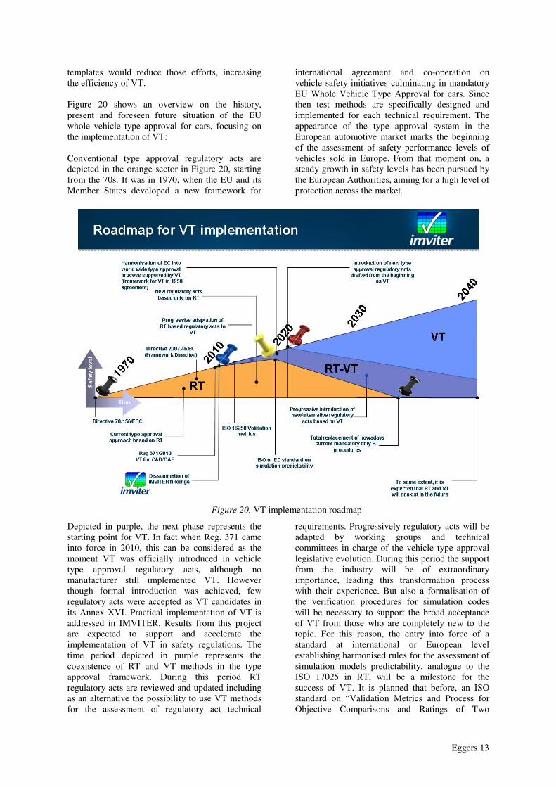
templates would reduce those efforts, increasing the efficiency of VT. Figure 20 shows an overview on the history, present and foreseen future situation of the EU whole vehicle type approval for cars, focusing on the implementation of VT: Conventional type approval regulatory acts are depicted in the orange sector in Figure 20, starting from the 70s. It was in 1970, when the EU and its Member States developed a new framework for
international agreement and co-operation on vehicle safety initiatives culminating in mandatory EU Whole Vehicle Type Approval for cars. Since then test methods are specifically designed and implemented for each technical requirement. The appearance of the type approval system in the European automotive market marks the beginning of the assessment of safety performance levels of vehicles sold in Europe. From that moment on, a steady growth in safety levels has been pursued by the European Authorities, aiming for a high level of protection across the market.
Figure 20. VT implementation roadmap
Depicted in purple, the next phase represents the starting point for VT. In fact when Reg. 371 came into force in 2010, this can be considered as the moment VT was officially introduced in vehicle type approval regulatory acts, although no manufacturer still implemented VT. However though formal introduction was achieved, few regulatory acts were accepted as VT candidates in its Annex XVI. Practical implementation of VT is addressed in IMVITER. Results from this project are expected to support and accelerate the implementation of VT in safety regulations. The time period depicted in purple represents the coexistence of RT and VT methods in the type approval framework. During this period RT regulatory acts are reviewed and updated including as an alternative the possibility to use VT methods for the assessment of regulatory act technical
requirements. Progressively regulatory acts will be adapted by working groups and technical committees in charge of the vehicle type approval legislative evolution. During this period the support from the industry will be of extraordinary importance, leading this transformation process with their experience. But also a formalisation of the verification procedures for simulation codes will be necessary to support the broad acceptance of VT from those who are completely new to the topic. For this reason, the entry into force of a standard at international or European level establishing harmonised rules for the assessment of simulation models predictability, analogue to the ISO 17025 in RT, will be a milestone for the success of VT. It is planned that before, an ISO standard on “Validation Metrics and Process for Objective Comparisons and Ratings of Two
Eggers 14
Different Signals to Support Virtual Testing in Various Road Vehicle Crash Modes” will open the door to the arrival of simulation and VT dedicated standards. It is expected that any new regulation that will appear during this phase will take into account VT methods as a support to conventional RT methods, or even as an alternative. The pace of safety requirements increase will not be affected by the implementation of VT, since VT will be an assessment tool just like RT, and safety levels imposed to vehicles will not be dependent on how these safety levels are assessed. In parallel with the transition period, a new era depicted in blue will appear marked by the appearance of the first regulatory act drafted from the beginning taking into account VT techniques. It is expected that this will happen in the next 10 years. Before a regulatory act will be drafted supported by VT methods from the beginning, first it would be desirable that at least half of the existing RT based regulatory acts will be adapted to include VT. If this adaptation process is delayed in time, the starting point for the era of VT will be also delayed. Later, in the next 20 years, it is expected that all regulatory acts can be updated to include VT as an alternative. This will depend not only on the acceptance of VT methods, but also in the improvement of simulation techniques, since nowadays there are still physical phenomena that are not modelled with the necessary accuracy and predictability to be addressed with VT. In the next 30 years, most regulatory acts will be based on VT, however it is expected that in a few of them, still RT might be preferred by the industry, so probably although the implementation of VT will be constantly increasing, not all regulatory acts will be addressed with VT in the long term due to cost or technical reasons. VT will leverage a possible future International Whole Vehicle Type-Approval system. The World Forum for Harmonisation of Vehicle Regulations (WP.29) agreed in March 2010 on the need to review and update the 1958 Agreement, along with a view to introduce the concept of “International whole vehicle type-approval (IWVTA)”. Currently there are different test conditions specified in similar regulations in different regions of the world. The possibility to use simulation models validated in one country in any other country, would benefit a progressive adaptation and harmonisation of type approval requirements This IWVTA concept would offer the benefit to vehicle manufacturers of using internationally validated simulation models in the type approval procedure for their motor vehicles, instead of having all the vehicle's systems and components separately approved by each country applying the WVTA, and therefore would considerably simplify the regulatory burden on
vehicle manufacturers and enhance the free movement of motor vehicles. Contributions from all stakeholders involved in vehicles type approval and VT are necessary in order to achieve the milestones indicated in the roadmap, as well as the objectives. ACKNOWLEDGMENT The research presented in this paper was carried out within the European project IMVITER. This project was co-funded by the European Commission DG-Information Society and Media in the 7th Framework. The authors would like to thank all project partners for their contribution. More information about the project and all public deliverables can be found on the website www.imviter.com. REFERENCES [1] COMMISSION REGULATION (EU) No 371/2010 of 16 April 2010, replacing Annexes V, X, XV and XVI to Directive 2007/46/EC (Framework Directive) [2] American Society of Mechanical Engineers (2006). “Guide for Verification and Validation in Computational Solid Mechanics”, 2006. Standards Committee on Verification and Validation in Computational Solid Mechanics (PTC 60/V&V 10) [3] Gehre, Christian; Gades, Heinrich; Wernicke, Philipp (2009). „Objective Rating of Signals Using Test and Simulation Responses” ESV 2009 Conference, Stuttgart, Paper Number 09-0407. [4] European New Car Assessment Programme (Euro NCAP). 2013. “Pedestrian Testing Protocol V 6.2” [5] REGULATION (EC) No 78/2009 OF THE EUROPEAN PARLIAMENT AND OF THE COUNCIL of 14 January 2009 on the type-approval of motor vehicles with regard to the protection of pedestrians and other vulnerable road users, amending Directive 2007/46/EC and repealing Directives 2003/102/EC and 2005/66/EC [6] COMMISSION REGULATION (EC) No 631/2009 of 22 July 2009 laying down detailed rules for the implementation of Annex I to Regulation (EC) No 78/2009 of the European Parliament and of the Council on the type-approval of motor vehicles with regard to the protection of pedestrians and other vulnerable road users, amending Directive 2007/46/EC and repealing Directives 2003/102/EC and 2005/66/EC
Eggers 15
APPENDIX
Figure 21. Detailed flowchart for the Hybrid VT approach applied on the pilot case “Pedestrian Protection Regulation Head Impact”