Embed Size (px)
DESCRIPTION
Virtual Private Net
Citation preview
Institut National Polytechnique de Grenoble
THESISfor obtaining the degree of
DOCTOR OF THE INPG
Specialty: ”Computer Science: Systems and Communications”
presented and publicly discussed
by
Lina AL-CHAAL
Defensed on February 2, 2005
Title:
Dynamic and Easily Manageable Approachfor Secure IP VPN Environments
CIFRE Thesis prepared in
the INRIA Rhone-Alpes and Netcelo S.A.

2
Lina AL-CHAAL 2004 Ph.D Thesis
INSTITUT NATIONAL POLYTECHNIQUE DEGRENOBLE
No assigned by the library
THESIS
for obtaining the degree of
DOCTOR OF THE INPG
Speciality: � Computer Science: Systems and Communications �
prepared at INRIA Rhone Alpes, Planete project-team
in the executive of The Doctoral School � MATHEMATIQUE, SCIENCESET TECHNOLOGIE DE L’INFORMATION �
presented and publicly discussed
by
Lina AL-CHAAL
Defensed on February 2, 2005
Title:
Dynamic and Easily Manageable Approach
for Secure IP VPN Environments
Director of thesis :Andrzej DUDA
Committee in charge
Prof. Jacques MOSSIERE President
Prof. Abdelmadjid BOUABDALLAH Reporter
Dr. Ahmed SERHROUCHNI Reporter
Prof. Andrzej DUDA Director of thesis
Dr. Vincent ROCA Supervisor
Dr. Michel HABERT Supervisor
Dr. Marco CARUGI Examiner

4
Lina AL-CHAAL 2004 Ph.D Thesis
INSTITUT NATIONAL POLYTECHNIQUE DEGRENOBLE
Noattribue par la bibliotheque
THESE
pour obtenir le grade de
DOCTEUR DE L’INPG
Specialite: �Informatique: Systemes et Communications�
preparee a l’INRIA Rhone Alpes, projet Planete
dans le cadre de l’Ecole Doctorale � MATHEMATIQUE, SCIENCES ETTECHNOLOGIE DE L’INFORMATION �
presentee et soutenue publiquement
par
Lina AL-CHAAL
le 2 Fevrier 2005
Titre:
Une Approche Dynamique et Facilement
Administrablepour des Environments IPVPN Securises
Directeur de these :Andrzej DUDA
Jury
Prof. Jacques MOSSIERE President
Prof. Abdelmadjid BOUABDALLAH Rapporteur
Dr. Ahmed SERHROUCHNI Rapporteur
Prof. Andrzej DUDA Directeur de these
Dr. Vincent ROCA Encadrament scientifique
Dr. Michel HABERT Encadrament scientifique
Dr. Marco CARUGI Examinateur

6
Lina AL-CHAAL 2004 Ph.D Thesis
Acknowledgment
I want to express my sincere acknowledgment to all those who have encouraged me, withtheir support and suggestions, all the long way of my Phd.
I would like to extend a special thanks to Prof. Xavier Rousset de Pina for encouraging meto pursue my studies in France.
Special appreciation is given to my supervisors Dr. Vincent ROCA and Dr. Michel HABERTwho provided me with insights, resources, direction, and continuous feedback, which was in-valuable and helped me gain much needed perspective. I would like to thank Prof. AndrzejDUDA for his advice and encouragement throughout my thesis.
All my gratitude to prof. Abdelmadjid BOUABDALLAH and Dr. Ahmed SERHROUCHNIfor the time they spent reading and commenting my thesis, and for the report they wrote.And I also would like to thank Dr. Marco CARUGI and Prof. Jacques MOSSIERE for takingpart in the committee and for their invaluable notes.
I would also like to thank all those who helped, advised, and gave fruitful discussions duringthis work. Many thanks also are to all my colleagues in Netcelo S.A. and the members ofthe Planete project in Inria Rhone Alpes. I also wish to express appreciation to Mr. CiaranDEIGNAN for his support and assistance with the technologies required for implementingthis study.
My sincere appreciation and gratitude to my parents for their support and encouragementduring the entire period of this thesis.
Finally, my deepest gratitude goes to the departed soul of my grandfather for his uncondi-tional love and his spiritual support throughout the last two years of his life.
I

II
Lina AL-CHAAL 2004 Ph.D Thesis
Our Achievements: PublishedPapers and Implementations
Magazine Papers
1. Lina Al-Chaal, Vincent Roca, and Michel Habert, Managing and Securing WebServices with VPNs, International Journal of Web Services Research JWSR, http://www.idea-group.com/journals/details.asp?id=4138, submitted work, after the invitation ofDr. Liang-Jie Zhang, the founding Editor-in-Chief of the JWSR.
Conference Papers
1. Lina Al-Chaal, Vincent Roca, and Michel Habert, Offering a multicast deliveryservice in a programmable secure ip vpn environment, Fourth InternationalWorkshop on Networked Group Communication - NGC’02, Boston, USA, October,2002.
2. Lina Al-Chaal, Vincent Roca, Ayman El-Sayed, and Michel Habert, A VPRN Solu-tion for Fully Secure and Efficient Group Communications, IEEE Symposiumon Computers and Communications - ISCC’2003, Kemer-Antalya, Turkey, July, 2003.An extended version is available as INRIA Research Report number RR-4799, INRIA,Rhone Alpes, France, April, 2003.
3. Lina Al-Chaal, Vincent Roca, and Michel Habert, Managing and Securing WebServices with VPNs, the second IEEE International Conference on Web Services -ICWS 2004, San Diego, California, USA, July, 2004.
4. Lina Al-Chaal, Vincent Roca, and Michel Habert, De l’Utilisation des VPNs pourl’Administration et la Securite des Services Web, 3eme Conference sur la Securiteet Architectures Reseaux - SAR 2004, La Londe, Cote d’Azur, France, June 2004.
Software (Perl/Java/C/Linux)
1. Internet VPN Group Management Protocol IVGMP implementation .
2. HAVA implementation for load balancing for VPN devices.
3. Implementation of VPN web services.
III

IV
Lina AL-CHAAL 2004 Ph.D Thesis
Abstract
The increased use of the global Internet and IP-based applications have paved the way forservice providers to offer new network services to their customers. The telecommunications’world reflects and embodies a fundamental shift in how service providers do business withoutdepending on ISP core networks that offer service oriented networks that bundles value-added services (such as packet telephony and e-commerce) on top of transport services. Alsoas network services become increasingly complex and network-intensive, customers want totap the outsourcing potential of service provider services for cost savings. Thus to offer costeffective network services, service providers will be challenged to deploy their services overpublic networks like the Internet and heightened by changes in business customer networks.In this dissertation, we introduce a CE-based VPN approach that offers different managementnetwork services in behalf of customers. This approach shifts the management hassles fromcustomer’s side to the VPN service provider. Yet by using this approach service providershave only to care about managing customers edge devices that are the gateways to the cus-tomers’ networks. This approach is a centralized solution, where everything, including VPNcreation, deployment and membership management, is under the control of a single Man-agement Operation Point (MOP). This thesis focuses on three key aspects: management,dynamism and security. We also investigate the use of our approach to offer group commu-nication services (e.g. Multicast service) and to manage and secure web services, yet otherfields of applications are possible, like the dynamic management of firewalls or VoIP.
V

VI
Lina AL-CHAAL 2004 Ph.D Thesis
Resume
Dans cette these, nous presentons une approache dynamique et facilement administrablebasee sur la technologie des reseaux prives virtuels IP, connus sous le nom ”IP Virtual PrivateNetworks” (IPVPNs). Avec cette approche les machines terminales, les serveurs et/ou desrouteurs de bordure s’organisent automatiquement en une topologie de recouvrement gracea laquelle des donnees sont diffusees. Cette approche est une solution centralisee, ou tout,y compris la gestion des services d’adminstration comme l’adhesion au groupe et la creationde topologie VPN, est de la responsabilite d’un centre d’operations du systeme, appele le”Network Operation System” (NOS).Nous utilisons notre approache pour etablir un service alternatif de communication de groupequi deplace le support de multipoint depuis les routeurs vers les extremites. Nous appliquonscette approache au moyen d’un nouveau protocole IVGMP (Internet Virtual Group Manage-ment Protocol) pour realiser un VPN supportant la diffusion multipoint sur des reseaux detransport IPV4.Nous etudions ensuite l’utilisation d’un nouveau protocole HBM qui fournit un service dedistribution multipoint au niveau applicatif afin d’etablir un service entierement securisemais efficace de communication de groupe entre plusieurs sites avec l’aide de notre approcheVPN. Nous montrons que HBM et notre approche sont naturellement complementaires etconduisent au concept de reseau prive virtuel route (VPRN).La deuxieme contribution concerne les services web securises. Nous definissons aussi unmodele d’architecture hybride qui s’applique aux Services Web. Nous montrons comment cemodele correspond bien a la nature dynamique des services web, offre un service d’administrationfacilement integrable, et ameliore grandement la securite des services web grace a l’utilisationde VPNs. La troisieme contribution de ce travail concerne des techniques de partage de chargeet d’amelioration de performances, telle l’addition de liens virtuels redandants qui evitent lapartition de la topologie en cas de panne d’une passerelle VPN.Nous concluons ce travail avec une discussion de differents applications de notre approcheIPVPN, en particulier des services qui peuvent etre fournis moyennant quelques modifica-tions.
VII

VIII
Lina AL-CHAAL 2004 Ph.D Thesis
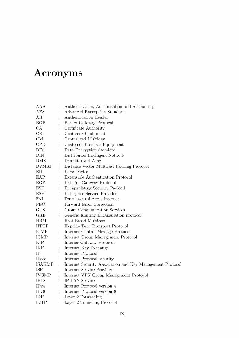
Acronyms
AAA : Authentication, Authorization and AccountingAES : Advanced Encryption StandardAH : Authentication HeaderBGP : Border Gateway ProtocolCA : Certificate AuthorityCE : Customer EquipmentCM : Centralized MulticastCPE : Customer Premises EquipmentDES : Data Encryption StandardDIN : Distributed Intelligent NetworkDMZ : Demilitarized ZoneDVMRP : Distance Vector Multicast Routing ProtocolED : Edge DeviceEAP : Extensible Authentication ProtocolEGP : Exterior Gateway ProtocolESP : Encapsulating Security PayloadESP : Enterprise Service ProviderFAI : Fournisseur d’Acces InternetFEC : Forward Error CorrectionGCS : Group Communication ServicesGRE : Generic Routing Encapsulation protocolHBM : Host Based MulticastHTTP : Hypride Text Transport ProtocolICMP : Internet Control Message ProtocolIGMP : Internet Group Management ProtocolIGP : Interior Gateway ProtocolIKE : Internet Key ExchangeIP : Internet ProtocolIPsec : Internet Protocol securityISAKMP : Internet Security Association and Key Management ProtocolISP : Internet Service ProviderIVGMP : Internet VPN Group Management ProtocolIPLS : IP LAN ServiceIPv4 : Internet Protocol version 4IPv6 : Internet Protocol version 6L2F : Layer 2 ForwardingL2TP : Layer 2 Tunneling Protocol
IX
X
L2VPN : Layer 2-based VPNL3VPN : Layer 3-based VPNLAN : Local Area NetworkMBone : Multicast backBoneMOP : Management Operation PointMPLS : Multi-Protocol Label SwitchingMPPE : Microsoft’s Point-to-Point EncryptionMS-CHAP : Microsoft Challenge Handshake Authentication ProtocolMSEC : Multicast SECurityNAS : Network Access ServerNAT : Network Address TranslationNOS : Network Operation SystemNSP : Network Service ProviderOSI : Open Systems Interconnection Reference ModelOSPF : Open Shortest Path FirstP : Provider routerPE : Provider EdgePGP : Pretty Good PrivacyPIM : Protocol Independent MulticastPIM-DM : Protocol Independent Multicast-Dense ModePIM-SM : Protocol Independent Multicast-Sparse ModePIM-SSM : Protocol Independent Multicast-Source Specific ModePOP : Point Of PresencePPP : Point-to-Point ProtocolPPTP : Point-to-Point Tunneling ProtocolPPVPN : Provider Provisioned Virtual Private NetworksQoS : Quality of ServiceRAS : Remote Access ServerRDP : Remote Desktop ProtocolRFC : Request for CommentRP : Rendez-vous PointRTT : Round-Trip TimeRTP : Real-Time Transport ProtocolSA : Security AssociationsSDP : Session Description ProtocolSIP : Session Initiation ProtocolSLA : Service-Level AgreementSNMP : Simple Network Management protocolSOAP : Simple Object Access ProtocolSP : Service ProviderSSL : Secure Socket LayerTBCP : Tree Based Control Protocol
Lina AL-CHAAL 2004 Ph.D Thesis
XI
TCP : Transmission Control ProtocolTTL : Time To LiveUDP : User Datagram ProtocolVC : Virtual CircuitVC : Virtual ChannelVNOC : Virtual Network Operation CenterVPDN : Virtual Private Dial-up NetworkVPLS : Virtual Private LAN ServiceVPN : Virtual Private NetworkVPRN : Virtual Private Routed NetworkVPWS : Virtual Private Wire ServiceVRF : VPN Routing and ForwardingVSI : VPN Switching InstanceWAN : Wide Area Network
Lina AL-CHAAL 2004 Ph.D Thesis

XII
Lina AL-CHAAL 2004 Ph.D Thesis
Contents
1 Introduction 11.1 VPN Definition . . . . . . . . . . . . . . . . . . . . . . . . . . . . . . . . . . . 1
1.1.1 A Bit of History . . . . . . . . . . . . . . . . . . . . . . . . . . . . . . 2
1.1.2 A Simple Example to Better Understand VPNs . . . . . . . . . . . . . 21.1.3 VPN Benefits . . . . . . . . . . . . . . . . . . . . . . . . . . . . . . . . 3
1.2 VPN Management Requirements . . . . . . . . . . . . . . . . . . . . . . . . . 41.3 Standards and Reference Models . . . . . . . . . . . . . . . . . . . . . . . . . 5
1.3.1 Distributed Intelligent Network (DIN) model . . . . . . . . . . . . . . 51.3.2 Concept of tunnel broker . . . . . . . . . . . . . . . . . . . . . . . . . 61.3.3 Policy based management . . . . . . . . . . . . . . . . . . . . . . . . . 6
1.4 Goals of the Thesis . . . . . . . . . . . . . . . . . . . . . . . . . . . . . . . . . 71.5 Organization of the Document . . . . . . . . . . . . . . . . . . . . . . . . . . 8
I Overview of VPN Technologies and Models 9
2 Survey of VPN technologies and their Management 112.1 Introduction . . . . . . . . . . . . . . . . . . . . . . . . . . . . . . . . . . . . . 112.2 ISP Network Components Terminology . . . . . . . . . . . . . . . . . . . . . . 12
2.3 VPN Technology in the Telecommunication World . . . . . . . . . . . . . . . 132.3.1 VPN Working Groups . . . . . . . . . . . . . . . . . . . . . . . . . . . 132.3.2 Tunneling Mechanisms . . . . . . . . . . . . . . . . . . . . . . . . . . . 152.3.3 IPsec VPN Tunneling Mechanism . . . . . . . . . . . . . . . . . . . . . 16
IPsec Definition . . . . . . . . . . . . . . . . . . . . . . . . . . . . . . . 16
IPsec Communication Channels . . . . . . . . . . . . . . . . . . . . . . 16IPsec Modes: Transport and Tunnel . . . . . . . . . . . . . . . . . . . 16Encryption Mechanisms . . . . . . . . . . . . . . . . . . . . . . . . . . 18Internet Key Exchange IKE . . . . . . . . . . . . . . . . . . . . . . . . 19
2.3.4 SSL VPN Tunneling Mechanism . . . . . . . . . . . . . . . . . . . . . 232.3.5 IPsec versus SSL VPN . . . . . . . . . . . . . . . . . . . . . . . . . . . 252.3.6 Other Tunneling Protocols . . . . . . . . . . . . . . . . . . . . . . . . 272.3.7 Different Connectivity VPN Models . . . . . . . . . . . . . . . . . . . 29
2.4 Various Types of IPVPN Solutions . . . . . . . . . . . . . . . . . . . . . . . . 312.4.1 IPVPN definition . . . . . . . . . . . . . . . . . . . . . . . . . . . . . . 322.4.2 General Classifications of IPVPN Types . . . . . . . . . . . . . . . . 322.4.3 CE-based IPVPN Details . . . . . . . . . . . . . . . . . . . . . . . . . 332.4.4 Provider-based VPN Details . . . . . . . . . . . . . . . . . . . . . . . . 34
L2VPN . . . . . . . . . . . . . . . . . . . . . . . . . . . . . . . . . . . 34L3VPN . . . . . . . . . . . . . . . . . . . . . . . . . . . . . . . . . . . 37
XIII
XIV CONTENTS
L3VPN vs L2VPN . . . . . . . . . . . . . . . . . . . . . . . . . . . . . 382.5 VPN Management Challenges . . . . . . . . . . . . . . . . . . . . . . . . . . . 38
2.6 Partial Conclusions . . . . . . . . . . . . . . . . . . . . . . . . . . . . . . . . . 41
3 Our Dynamic CE-based VPN Approach 433.1 Introduction . . . . . . . . . . . . . . . . . . . . . . . . . . . . . . . . . . . . . 433.2 Architecture . . . . . . . . . . . . . . . . . . . . . . . . . . . . . . . . . . . . . 44
3.2.1 Classification of our Approach . . . . . . . . . . . . . . . . . . . . . . 443.2.2 General Description . . . . . . . . . . . . . . . . . . . . . . . . . . . . 45
Customer Related Information . . . . . . . . . . . . . . . . . . . . . . 45Core Network versus Logical Layer . . . . . . . . . . . . . . . . . . . . 46VNOC Functionalities . . . . . . . . . . . . . . . . . . . . . . . . . . . 47
CE/VNOC Messages . . . . . . . . . . . . . . . . . . . . . . . . . . . . 48Security Protocols . . . . . . . . . . . . . . . . . . . . . . . . . . . . . 48
3.2.3 Technical Details . . . . . . . . . . . . . . . . . . . . . . . . . . . . . . 48Initial Phase: Initialization of CE Devices . . . . . . . . . . . . . . . . 48
Configuration of CE devices . . . . . . . . . . . . . . . . . . . . . . . . 49Negotiation of IPsec Parameters . . . . . . . . . . . . . . . . . . . . . 49Exchanging Data Between Two CE Devices . . . . . . . . . . . . . . . 49Turning Down an IPsec Tunnel . . . . . . . . . . . . . . . . . . . . . . 50
3.3 Dynamic Management versus Manual Management . . . . . . . . . . . . . . . 503.4 Implementation Details . . . . . . . . . . . . . . . . . . . . . . . . . . . . . . 52
3.4.1 The SMS Architecture . . . . . . . . . . . . . . . . . . . . . . . . . . . 523.4.2 The SES Architecture . . . . . . . . . . . . . . . . . . . . . . . . . . . 52
3.5 Features of our Approach: a Summary . . . . . . . . . . . . . . . . . . . . . . 54
II Some Contributions for the CE-based VPN Approach 57
4 Basic Group Communication Services 594.1 Background . . . . . . . . . . . . . . . . . . . . . . . . . . . . . . . . . . . . . 60
4.1.1 Limitations of IETF Solutions for Supporting Multicast over VPNs . . 60Multicast study over VPNs . . . . . . . . . . . . . . . . . . . . . . . . 60
Security of multicast . . . . . . . . . . . . . . . . . . . . . . . . . . . . 614.1.2 Our Approach for Secure Group Communications . . . . . . . . . . . . 61
4.2 Our Approach: IVGMP Architecture . . . . . . . . . . . . . . . . . . . . . . . 634.2.1 The Virtual Router Concept . . . . . . . . . . . . . . . . . . . . . . . 63
4.2.2 IVGMP Detailed Description . . . . . . . . . . . . . . . . . . . . . . . 634.2.3 IVGMP Critical Appraisal . . . . . . . . . . . . . . . . . . . . . . . . . 65
4.3 Implementation Aspects . . . . . . . . . . . . . . . . . . . . . . . . . . . . . . 664.4 Partial Conclusions . . . . . . . . . . . . . . . . . . . . . . . . . . . . . . . . . 67
5 Using Application Level Multicast for Improved Group CommunicationEfficiency: the VPRN Concept 695.1 Background . . . . . . . . . . . . . . . . . . . . . . . . . . . . . . . . . . . . . 70
5.1.1 Limitations of our CE-based VPN approach . . . . . . . . . . . . . . . 70Security Versus Scalability . . . . . . . . . . . . . . . . . . . . . . . . . 70Limits of the IVGMP Architecture . . . . . . . . . . . . . . . . . . . . 70
5.1.2 The Benefits of the VPRN and Overlay Multicast Solutions . . . . . . 71The Traditional VPRN Concept Versus our View of a VPRN . . . . . 71
Lina AL-CHAAL 2004 Ph.D Thesis
CONTENTS XV
The Overlay Multicast Concept and the HBM Protocol . . . . . . . . 725.2 Our Approach: The IVGMP/HBM Architecture . . . . . . . . . . . . . . . . 72
5.2.1 General Architecture . . . . . . . . . . . . . . . . . . . . . . . . . . . . 725.2.2 Detailed Description . . . . . . . . . . . . . . . . . . . . . . . . . . . . 74
CE device Functionalities . . . . . . . . . . . . . . . . . . . . . . . . . 74VNOC/RP Functionalities . . . . . . . . . . . . . . . . . . . . . . . . . 74
5.3 Performance Evaluations . . . . . . . . . . . . . . . . . . . . . . . . . . . . . . 75
5.3.1 Experimental Conditions . . . . . . . . . . . . . . . . . . . . . . . . . 755.3.2 Metrics Considered . . . . . . . . . . . . . . . . . . . . . . . . . . . . . 755.3.3 Results and Discussion . . . . . . . . . . . . . . . . . . . . . . . . . . . 76
5.4 Partial Conclusions . . . . . . . . . . . . . . . . . . . . . . . . . . . . . . . . . 76
6 Managing and Securing Web Services with VPNs 796.1 Background . . . . . . . . . . . . . . . . . . . . . . . . . . . . . . . . . . . . . 79
6.1.1 Requirements for Standard Technologies in our VPN Approach . . . . 806.1.2 Web Services Evolution and Challenges . . . . . . . . . . . . . . . . . 80
Web Service Architecture . . . . . . . . . . . . . . . . . . . . . . . . . 80Evolution of Web Services and Open Challenges . . . . . . . . . . . . 81Related Works in Security and Management Services . . . . . . . . . . 83
6.2 Our Approach: VPN Web Services Architecture . . . . . . . . . . . . . . . . . 84
6.2.1 Introduction to the VPN Web Service Architecture . . . . . . . . . . . 846.2.2 VPN Web Service Phases . . . . . . . . . . . . . . . . . . . . . . . . . 85
Signaling Phase and VPN Branch Setup: . . . . . . . . . . . . . . . . 85Data Transfer Phase: . . . . . . . . . . . . . . . . . . . . . . . . . . . . 86Example . . . . . . . . . . . . . . . . . . . . . . . . . . . . . . . . . . . 87
6.3 Implementation and Evaluation of a VPN Web Service Platform . . . . . . . 886.4 Partial Conclusions . . . . . . . . . . . . . . . . . . . . . . . . . . . . . . . . . 90
7 Adding Load Balancing to our VPN Approach for Higher Availability orHigher Performance 937.1 Background . . . . . . . . . . . . . . . . . . . . . . . . . . . . . . . . . . . . . 93
7.2 Definitions . . . . . . . . . . . . . . . . . . . . . . . . . . . . . . . . . . . . . . 947.3 Our First Approach: Load Balancing and High Availability Architecture . . . 95
7.3.1 Agent Routing Tables . . . . . . . . . . . . . . . . . . . . . . . . . . . 977.3.2 Scenario . . . . . . . . . . . . . . . . . . . . . . . . . . . . . . . . . . . 97
7.3.3 Implementation Aspects . . . . . . . . . . . . . . . . . . . . . . . . . . 997.4 Redundancy versus Memory Overhead . . . . . . . . . . . . . . . . . . . . . . 997.5 Our Second Approach: Load Balancing and High Performance Architecture . 101
7.5.1 Hubs or Switches . . . . . . . . . . . . . . . . . . . . . . . . . . . . . . 1017.5.2 Router Example to Better Understand . . . . . . . . . . . . . . . . . . 101
7.5.3 VPN Gateway Cluster . . . . . . . . . . . . . . . . . . . . . . . . . . . 1037.6 Partial Conclusions . . . . . . . . . . . . . . . . . . . . . . . . . . . . . . . . . 105
III Discussion, Conclusions, and Future Work 107
8 Discussion, Conclusions and Future Works 1098.1 General Discussion . . . . . . . . . . . . . . . . . . . . . . . . . . . . . . . . . 110
8.1.1 Security . . . . . . . . . . . . . . . . . . . . . . . . . . . . . . . . . . . 110Discussion . . . . . . . . . . . . . . . . . . . . . . . . . . . . . . . . . . 110
Lina AL-CHAAL 2004 Ph.D Thesis
XVI CONTENTS
Contributions and Future Works . . . . . . . . . . . . . . . . . . . . . 110
8.1.2 Scalability . . . . . . . . . . . . . . . . . . . . . . . . . . . . . . . . . . 111
Discussion . . . . . . . . . . . . . . . . . . . . . . . . . . . . . . . . . . 111
Contributions and Future Works . . . . . . . . . . . . . . . . . . . . . 111
8.1.3 Robustness . . . . . . . . . . . . . . . . . . . . . . . . . . . . . . . . . 111
Discussion . . . . . . . . . . . . . . . . . . . . . . . . . . . . . . . . . . 111
Contributions and Future Works . . . . . . . . . . . . . . . . . . . . . 112
8.1.4 Performance . . . . . . . . . . . . . . . . . . . . . . . . . . . . . . . . 112
Discussion . . . . . . . . . . . . . . . . . . . . . . . . . . . . . . . . . . 112
Contributions and Future Works . . . . . . . . . . . . . . . . . . . . . 112
8.1.5 Relationship with Active and Programmable Networks . . . . . . . . . 113
8.1.6 Other Related Works . . . . . . . . . . . . . . . . . . . . . . . . . . . . 113
8.2 Another field of application: NAT and its Challenges . . . . . . . . . . . . . . 113
8.2.1 Discussion . . . . . . . . . . . . . . . . . . . . . . . . . . . . . . . . . . 113
8.2.2 Contributions and Future Works . . . . . . . . . . . . . . . . . . . . . 114
8.3 Another field of application: Introducing Dynamic Firewalls Management toour CE-based VPN Model . . . . . . . . . . . . . . . . . . . . . . . . . . . . . 115
8.3.1 Improving Filtering in our VPN Model . . . . . . . . . . . . . . . . . . 115
8.3.2 Needs for Dynamic Firewall Management . . . . . . . . . . . . . . . . 116
8.4 Another field of application: Security and VoIP . . . . . . . . . . . . . . . . 117
8.4.1 Discussion . . . . . . . . . . . . . . . . . . . . . . . . . . . . . . . . . . 117
8.4.2 Contributions and Future Works . . . . . . . . . . . . . . . . . . . . . 117
9 Annex 119
9.1 Firewalls . . . . . . . . . . . . . . . . . . . . . . . . . . . . . . . . . . . . . . . 119
9.2 NATs . . . . . . . . . . . . . . . . . . . . . . . . . . . . . . . . . . . . . . . . 121
9.3 NATs and VoIP . . . . . . . . . . . . . . . . . . . . . . . . . . . . . . . . . . . 122
IV Resume en francais 125
10 Introduction 129
10.1 Contexte du travail . . . . . . . . . . . . . . . . . . . . . . . . . . . . . . . . . 129
10.1.1 Les Points Cles d’un Systeme VPN Bien Administre . . . . . . . . . . 129
10.1.2 L’Architecture Conceptuelle . . . . . . . . . . . . . . . . . . . . . . . . 131
10.2 Buts de ce travail et organisation du document . . . . . . . . . . . . . . . . . 132
11 Notre Approche: CE-based VPN Modele 135
11.1 Le Principe de Notre Approche . . . . . . . . . . . . . . . . . . . . . . . . . . 135
11.2 Description de Notre Approche . . . . . . . . . . . . . . . . . . . . . . . . . . 136
11.2.1 Utilisation de SSL et IPSec . . . . . . . . . . . . . . . . . . . . . . . . 137
11.2.2 Le Reseaux de Base et la Couche Logique . . . . . . . . . . . . . . . . 138
11.2.3 Les Messages CE/VNOC . . . . . . . . . . . . . . . . . . . . . . . . . 139
11.3 Details d’Implementation . . . . . . . . . . . . . . . . . . . . . . . . . . . . . 139
11.3.1 L’Architecture SMS . . . . . . . . . . . . . . . . . . . . . . . . . . . . 139
11.3.2 L’Architecture SES . . . . . . . . . . . . . . . . . . . . . . . . . . . . . 140
Lina AL-CHAAL 2004 Ph.D Thesis

CONTENTS XVII
12 Notre Contribution: dans les Services de Groupes de Communication 14312.1 Etat de l’Art: Services de Groupes de Communication . . . . . . . . . . . . . 143
12.1.1 Limitations de Support Multicast sur les VPNs . . . . . . . . . . . . . 144Multicast sur VPNs . . . . . . . . . . . . . . . . . . . . . . . . . . . . 144Securite du Multicast . . . . . . . . . . . . . . . . . . . . . . . . . . . 145
12.1.2 Notre Approche pour la Securite des Groupes de Communications . . 14512.2 Notre Approche: Architecture IVGMP . . . . . . . . . . . . . . . . . . . . . . 146
12.2.1 Le Concept du Routeur Virtuel . . . . . . . . . . . . . . . . . . . . . . 14612.2.2 Description Detaillee d’IVGMP . . . . . . . . . . . . . . . . . . . . . . 146
12.3 Implementation d’IVGMP . . . . . . . . . . . . . . . . . . . . . . . . . . . . . 14812.4 Autres Travaux dans le Domaine . . . . . . . . . . . . . . . . . . . . . . . . . 149
13 Notre Contribution: dans les Services Web 15113.1 Etat de l’Art: Services Web . . . . . . . . . . . . . . . . . . . . . . . . . . . . 151
13.1.1 Architecture d’un Service Web . . . . . . . . . . . . . . . . . . . . . . 15113.1.2 Evolution des Services Web et Challenges Associes . . . . . . . . . . . 152
Challenges Lies a l’Administration . . . . . . . . . . . . . . . . . . . . 153Challenges Lies a la Securite . . . . . . . . . . . . . . . . . . . . . . . 153
13.2 Notre Approche: Services Web VPN . . . . . . . . . . . . . . . . . . . . . . . 15413.2.1 Architecture . . . . . . . . . . . . . . . . . . . . . . . . . . . . . . . . 15413.2.2 Les Deux Phase d’Etablissement d’un Service Web VPN . . . . . . . . 155
Phase de Signalisation et d’Installation du VPN . . . . . . . . . . . . 155Phase de Transfert de Donnees . . . . . . . . . . . . . . . . . . . . . . 156
13.3 Implementation et Evaluation des Services Web VPN . . . . . . . . . . . . . 15613.4 Autres Travaux dans le Domaine . . . . . . . . . . . . . . . . . . . . . . . . . 158
Lina AL-CHAAL 2004 Ph.D Thesis

XVIII CONTENTS
Lina AL-CHAAL 2004 Ph.D Thesis
List of Figures
1.1 The Tunnel Broker Model . . . . . . . . . . . . . . . . . . . . . . . . . . . . . 61.2 The Policy Based Management . . . . . . . . . . . . . . . . . . . . . . . . . . 7
2.1 ISP Network and Elements . . . . . . . . . . . . . . . . . . . . . . . . . . . . 132.2 AH Location in IPsec Packet . . . . . . . . . . . . . . . . . . . . . . . . . . . 172.3 ESP Location in IPsec Packet . . . . . . . . . . . . . . . . . . . . . . . . . . . 182.4 IKE Main Mode with Signatures . . . . . . . . . . . . . . . . . . . . . . . . . 20
2.5 IKE Quick Mode . . . . . . . . . . . . . . . . . . . . . . . . . . . . . . . . . . 212.6 Remote control SSL VPN . . . . . . . . . . . . . . . . . . . . . . . . . . . . . 252.7 PPTP control and data frames . . . . . . . . . . . . . . . . . . . . . . . . . . 28
2.8 PPTP applications . . . . . . . . . . . . . . . . . . . . . . . . . . . . . . . . . 292.9 L2TP/IPsec control and data frames . . . . . . . . . . . . . . . . . . . . . . . 302.10 VPN Family Tree . . . . . . . . . . . . . . . . . . . . . . . . . . . . . . . . . . 31
2.11 CE-based VPN model . . . . . . . . . . . . . . . . . . . . . . . . . . . . . . . 332.12 VPWS approach . . . . . . . . . . . . . . . . . . . . . . . . . . . . . . . . . . 352.13 VPLS approach . . . . . . . . . . . . . . . . . . . . . . . . . . . . . . . . . . . 36
2.14 MPLS Layer 2 VPN approach . . . . . . . . . . . . . . . . . . . . . . . . . . . 372.15 Kompella Layer 2 VPN approach . . . . . . . . . . . . . . . . . . . . . . . . . 382.16 BGP/MPLS architecture . . . . . . . . . . . . . . . . . . . . . . . . . . . . . 392.17 BGP/MPLS approach versus VPRN approach . . . . . . . . . . . . . . . . . 40
3.1 Various VPNs Applications . . . . . . . . . . . . . . . . . . . . . . . . . . . . 443.2 Our Approach into the VPN Family Tree . . . . . . . . . . . . . . . . . . . . 453.3 Architecture of our CE-based VPN approach. . . . . . . . . . . . . . . . . . . 46
3.4 General Description of our VPN Approach . . . . . . . . . . . . . . . . . . . . 473.5 Technical Components of the NOS . . . . . . . . . . . . . . . . . . . . . . . . 523.6 The SES Components . . . . . . . . . . . . . . . . . . . . . . . . . . . . . . . 53
3.7 JSP Model 2 in the SES . . . . . . . . . . . . . . . . . . . . . . . . . . . . . . 54
4.1 The virtual router concept. . . . . . . . . . . . . . . . . . . . . . . . . . . . . 634.2 Joining a Multicast Group as a Client. . . . . . . . . . . . . . . . . . . . . . . 644.3 An architectural view of packet processing in IVGMP. . . . . . . . . . . . . . 66
5.1 RFC 2764 versus ours VPRN architecture for group communications. . . . . . 715.2 The non-routed versus VPRN approaches for group communications in a VPN
environment. . . . . . . . . . . . . . . . . . . . . . . . . . . . . . . . . . . . . 735.3 Multi-unicast versus constrained shared tree comparison . . . . . . . . . . . . 76
5.4 Multi-unicast versus constrained shared tree link stress comparison. . . . . . 77
6.1 Web Service Architecture. . . . . . . . . . . . . . . . . . . . . . . . . . . . . . 81
XIX
XX LIST OF FIGURES
6.2 Building Web Service VPN: Signaling Phase. . . . . . . . . . . . . . . . . . . 856.3 Building Web Service VPN: Data Transfer Phase. . . . . . . . . . . . . . . . . 876.4 Processing time of a Join message (histogram). . . . . . . . . . . . . . . . . . 886.5 Processing time of a Leave message (histogram). . . . . . . . . . . . . . . . . 896.6 Processing time of a GetVPN message (histogram). . . . . . . . . . . . . . . . 906.7 Update time of a VPN web service (histogram). . . . . . . . . . . . . . . . . . 916.8 Processing time of GetVPN messages sent simultaneously by several clients. . 91
7.1 Cluster Model . . . . . . . . . . . . . . . . . . . . . . . . . . . . . . . . . . . . 957.2 Initial Phase . . . . . . . . . . . . . . . . . . . . . . . . . . . . . . . . . . . . 977.3 Backup Phase . . . . . . . . . . . . . . . . . . . . . . . . . . . . . . . . . . . . 987.4 Transferring VPN functionalities in case of CE devices failure . . . . . . . . . 1007.5 Four Node High Performance Router Cluster . . . . . . . . . . . . . . . . . . 1027.6 A High Performance VPN Gateway Cluster . . . . . . . . . . . . . . . . . . . 104
8.1 Integrating STUN in The NOS for IKE Applications . . . . . . . . . . . . . . 1148.2 Applying Dynamic Management for Firewalls in our VPN Model . . . . . . . 116
9.1 The Full Cone NAT and The Restricted Cone NAT . . . . . . . . . . . . . . . 1229.2 The Port Restricted Cone NAT and The Symmetric NAT . . . . . . . . . . . 123
10.1 Le Modele PBN . . . . . . . . . . . . . . . . . . . . . . . . . . . . . . . . . . . 132
11.1 Differents Applications VPNs . . . . . . . . . . . . . . . . . . . . . . . . . . . 13611.2 L’Architecture de Notre Approche CE-based VPN . . . . . . . . . . . . . . . 13711.3 La Description de notre Approche VPN . . . . . . . . . . . . . . . . . . . . . 13811.4 Les Composants Techniques de NOS . . . . . . . . . . . . . . . . . . . . . . . 14011.5 Les Composants de SES . . . . . . . . . . . . . . . . . . . . . . . . . . . . . . 141
12.1 Le concept du routeur virtuel. . . . . . . . . . . . . . . . . . . . . . . . . . . . 14612.2 Joindre un groupe multicast (Client). . . . . . . . . . . . . . . . . . . . . . . . 14712.3 Vue architecturale du traitement des paquets IVGMP. . . . . . . . . . . . . . 148
13.1 Architecture d’un Service Web. . . . . . . . . . . . . . . . . . . . . . . . . . . 15213.2 Creation d’un Service Web VPN: phase de signalisation. . . . . . . . . . . . . 15513.3 Creation d’un Service Web VPN: phase de transfert de donnees. . . . . . . . 15613.4 Temps de traitement d’un message JOIN (histogramme). . . . . . . . . . . . 15713.5 Mise a jour d’un service web VPN (histogramme). . . . . . . . . . . . . . . . 15713.6 Temps de traitement de messages GetVPN envoyes simultanement par plusieurs
clients. . . . . . . . . . . . . . . . . . . . . . . . . . . . . . . . . . . . . . . . . 158
Lina AL-CHAAL 2004 Ph.D Thesis

List of Tables
7.1 Initial Situation . . . . . . . . . . . . . . . . . . . . . . . . . . . . . . . . . . . 987.2 Initial Routing Table . . . . . . . . . . . . . . . . . . . . . . . . . . . . . . . . 987.3 Backup Situation . . . . . . . . . . . . . . . . . . . . . . . . . . . . . . . . . . 997.4 Routing Table After Backup . . . . . . . . . . . . . . . . . . . . . . . . . . . . 99
XXI

XXII LIST OF TABLES
Lina AL-CHAAL 2004 Ph.D Thesis
Chapter 1
Introduction
Contents
1.1 VPN Definition . . . . . . . . . . . . . . . . . . . . . . . . . . . . . 1
1.1.1 A Bit of History . . . . . . . . . . . . . . . . . . . . . . . . . . . . . 2
1.1.2 A Simple Example to Better Understand VPNs . . . . . . . . . . . . 2
1.1.3 VPN Benefits . . . . . . . . . . . . . . . . . . . . . . . . . . . . . . . 3
1.2 VPN Management Requirements . . . . . . . . . . . . . . . . . . . 4
1.3 Standards and Reference Models . . . . . . . . . . . . . . . . . . . 5
1.3.1 Distributed Intelligent Network (DIN) model . . . . . . . . . . . . . 5
1.3.2 Concept of tunnel broker . . . . . . . . . . . . . . . . . . . . . . . . 6
1.3.3 Policy based management . . . . . . . . . . . . . . . . . . . . . . . . 6
1.4 Goals of the Thesis . . . . . . . . . . . . . . . . . . . . . . . . . . . 7
1.5 Organization of the Document . . . . . . . . . . . . . . . . . . . . 8
We start this chapter by giving a quick glance on the history that leads to the design of theVirtual Private Networks, or VPNs. We define them and introduce their benefits in general.We summarize the management obstacles that most current VPN models have to face, andthe essential points for a well-managed system. These considerations lead us to quicklyintroduce the need for a well-managed dynamic system over IPVPN. Finally we introducethe goals and the organization of this thesis.
1.1 VPN Definition
The idea behind VPNs is not new [50], but VPNs went a step further by offering the opportu-nity to create dynamic links over different transmission media [38]. In addition to offering abetter flexibility and scalability, a VPN provides a service functionally equivalent to a privatenetwork, using the shared resources of a public network. Typically a VPN uses an exist-ing infrastructure to establish secure communications between trusted associates in a verycost effective way. This infrastructure can be either an IP backbone from a Network ServiceProvider (NSP), or the whole Internet. In places, the infrastructure may be frame relay orATM carrying IP. In other words, a VPN simulates the behavior of dedicated WAN linksover leased lines.
1
2 CHAPTER 1. INTRODUCTION
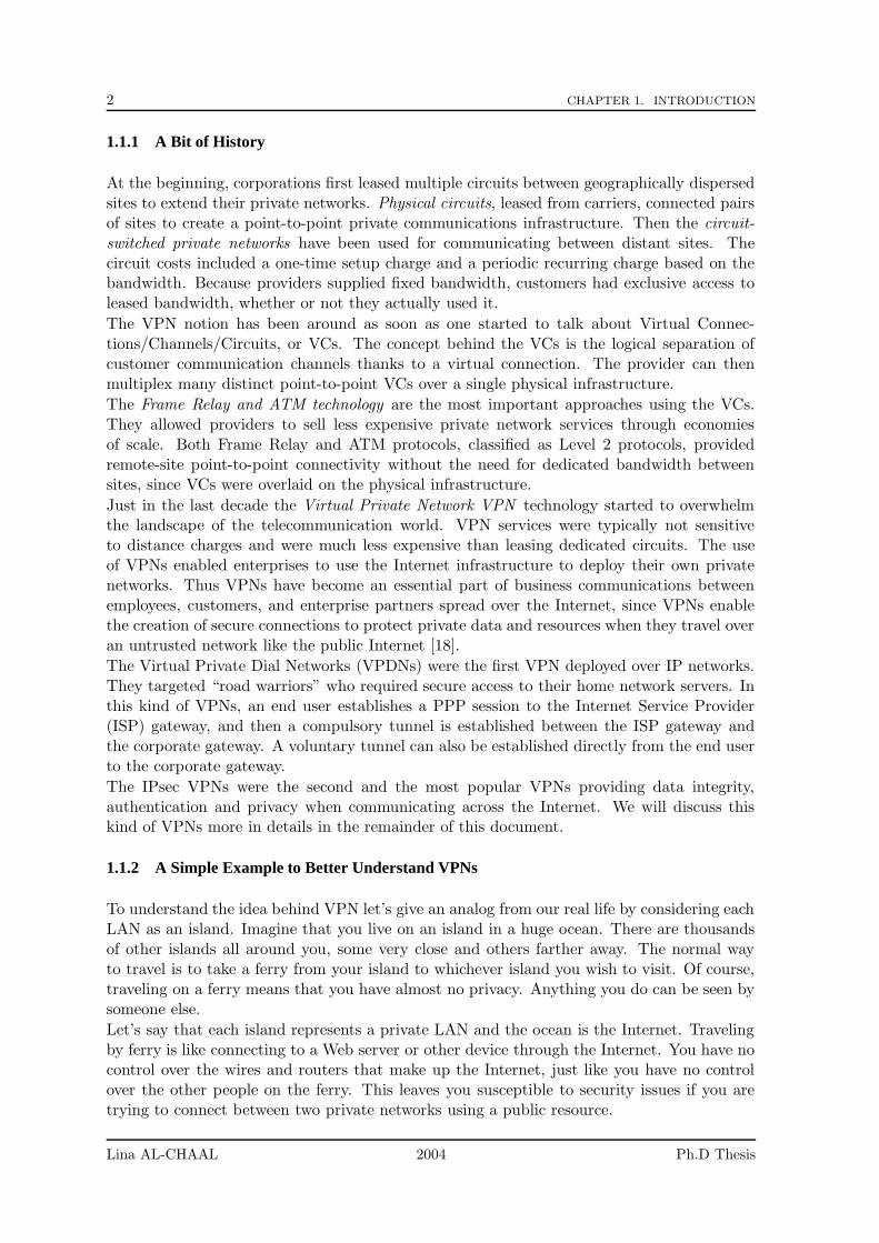
1.1.1 A Bit of History
At the beginning, corporations first leased multiple circuits between geographically dispersedsites to extend their private networks. Physical circuits, leased from carriers, connected pairsof sites to create a point-to-point private communications infrastructure. Then the circuit-switched private networks have been used for communicating between distant sites. Thecircuit costs included a one-time setup charge and a periodic recurring charge based on thebandwidth. Because providers supplied fixed bandwidth, customers had exclusive access toleased bandwidth, whether or not they actually used it.
The VPN notion has been around as soon as one started to talk about Virtual Connec-tions/Channels/Circuits, or VCs. The concept behind the VCs is the logical separation ofcustomer communication channels thanks to a virtual connection. The provider can thenmultiplex many distinct point-to-point VCs over a single physical infrastructure.
The Frame Relay and ATM technology are the most important approaches using the VCs.They allowed providers to sell less expensive private network services through economiesof scale. Both Frame Relay and ATM protocols, classified as Level 2 protocols, providedremote-site point-to-point connectivity without the need for dedicated bandwidth betweensites, since VCs were overlaid on the physical infrastructure.
Just in the last decade the Virtual Private Network VPN technology started to overwhelmthe landscape of the telecommunication world. VPN services were typically not sensitiveto distance charges and were much less expensive than leasing dedicated circuits. The useof VPNs enabled enterprises to use the Internet infrastructure to deploy their own privatenetworks. Thus VPNs have become an essential part of business communications betweenemployees, customers, and enterprise partners spread over the Internet, since VPNs enablethe creation of secure connections to protect private data and resources when they travel overan untrusted network like the public Internet [18].
The Virtual Private Dial Networks (VPDNs) were the first VPN deployed over IP networks.They targeted “road warriors” who required secure access to their home network servers. Inthis kind of VPNs, an end user establishes a PPP session to the Internet Service Provider(ISP) gateway, and then a compulsory tunnel is established between the ISP gateway andthe corporate gateway. A voluntary tunnel can also be established directly from the end userto the corporate gateway.
The IPsec VPNs were the second and the most popular VPNs providing data integrity,authentication and privacy when communicating across the Internet. We will discuss thiskind of VPNs more in details in the remainder of this document.
1.1.2 A Simple Example to Better Understand VPNs
To understand the idea behind VPN let’s give an analog from our real life by considering eachLAN as an island. Imagine that you live on an island in a huge ocean. There are thousandsof other islands all around you, some very close and others farther away. The normal wayto travel is to take a ferry from your island to whichever island you wish to visit. Of course,traveling on a ferry means that you have almost no privacy. Anything you do can be seen bysomeone else.
Let’s say that each island represents a private LAN and the ocean is the Internet. Travelingby ferry is like connecting to a Web server or other device through the Internet. You have nocontrol over the wires and routers that make up the Internet, just like you have no controlover the other people on the ferry. This leaves you susceptible to security issues if you aretrying to connect between two private networks using a public resource.
Lina AL-CHAAL 2004 Ph.D Thesis
1.1. VPN DEFINITION 3
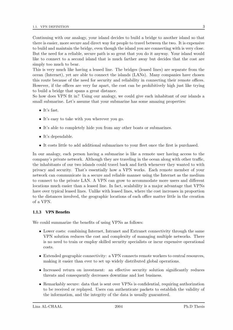
Continuing with our analogy, your island decides to build a bridge to another island so thatthere is easier, more secure and direct way for people to travel between the two. It is expensiveto build and maintain the bridge, even though the island you are connecting with is very close.But the need for a reliable, secure path is so great that you do it anyway. Your island wouldlike to connect to a second island that is much farther away but decides that the cost aresimply too much to bear.This is very much like having a leased line. The bridges (leased lines) are separate from theocean (Internet), yet are able to connect the islands (LANs). Many companies have chosenthis route because of the need for security and reliability in connecting their remote offices.However, if the offices are very far apart, the cost can be prohibitively high just like tryingto build a bridge that spans a great distance.So how does VPN fit in? Using our analogy, we could give each inhabitant of our islands asmall submarine. Let’s assume that your submarine has some amazing properties:
• It’s fast.
• It’s easy to take with you wherever you go.
• It’s able to completely hide you from any other boats or submarines.
• It’s dependable.
• It costs little to add additional submarines to your fleet once the first is purchased.
In our analogy, each person having a submarine is like a remote user having access to thecompany’s private network. Although they are traveling in the ocean along with other traffic,the inhabitants of our two islands could travel back and forth whenever they wanted to withprivacy and security. That’s essentially how a VPN works. Each remote member of yournetwork can communicate in a secure and reliable manner using the Internet as the mediumto connect to the private LAN. A VPN can grow to accommodate more users and differentlocations much easier than a leased line. In fact, scalability is a major advantage that VPNshave over typical leased lines. Unlike with leased lines, where the cost increases in proportionto the distances involved, the geographic locations of each office matter little in the creationof a VPN.
1.1.3 VPN Benefits
We could summarize the benefits of using VPNs as follows:
• Lower costs: combining Internet, Intranet and Extranet connectivity through the sameVPN solution reduces the cost and complexity of managing multiple networks. Thereis no need to train or employ skilled security specialists or incur expensive operationalcosts.
• Extended geographic connectivity: a VPN connects remote workers to central resources,making it easier than ever to set up widely distributed global operations.
• Increased return on investment: an effective security solution significantly reducesthreats and consequently decreases downtime and lost business.
• Remarkably secure: data that is sent over VPNs is confidential, requiring authorizationto be received or replayed. Users can authenticate packets to establish the validity ofthe information, and the integrity of the data is usually guaranteed.
Lina AL-CHAAL 2004 Ph.D Thesis
4 CHAPTER 1. INTRODUCTION
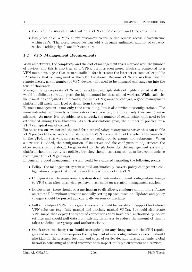
• Flexible: new users and sites within a VPN can be complex and time consuming.
• Easily scalable: a VPN allows customers to utilize the remote access infrastructurewithin ISPs. Therefore, companies can add a virtually unlimited amount of capacitywithout adding significant infrastructure.
1.2 VPN Management Requirements
With all networks, the complexity and the cost of management tasks increase with the numberof devices, and this is also true with VPNs, perhaps even more. Each site connected to aVPN must have a gear that secures traffic before it crosses the Internet or some other publicIP network that is being used as the VPN backbone. Because VPNs are so often used forremote access, as the number of VPN devices that need to be managed can range up into thetens of thousands.Managing large corporate VPNs requires adding multiple shifts of highly trained staff thatwould be difficult to retain given the high demand for these skilled workers. While each ele-ment must be configured and reconfigured as a VPN grows and changes, a good managementplatform will mask that level of detail from the user.Element management is not only time-consuming, but it also invites misconfigurations. Themore individual commands administrators have to enter, the more likely they are to makemistakes. As more sites are added to a network, the number of relationships that need to beestablished among them blossoms. As such associations grow, the number of policies for aVPN can spiral out of control.For these reasons we noticed the need for a central policy management server that can enableVPN policies to be set once and distributed to VPN servers at all of the other sites connectedto the VPN. In this way, servers can also be configured by groups and subgroups. Whena new site is added, the configuration of its server and the configuration adjustments theother servers require should be generated by the platform. So the management system orplatform should not only set policies, but they should also translate them into commands toreconfigure the VPN gateways.In general, a good management system could be evaluated regarding the following points:
• Policy: the management system should automatically convert policy changes into con-figuration changes that must be made at each node of the VPN.
• Configuration: the management system should automatically send configuration changesto VPN sites after these changes have been made on a central management station.
• Deployment: there should be a mechanism to distribute, configure and update softwareon remote PCs without someone manually setting up each machine. Updates and policychanges should be pushed automatically on remote machines.
• Full knowledge of VPN topologies: the system should be best-fit and support for tailoredVPN solutions (e.g. fully meshed and partially meshed VPNs). It should also createVPN maps that depict the types of connections that have been authorized by policysettings and should pull data from existing databases to reduce the amount of time ittakes to define user groups and authorizations.
• Quick reaction: the system should react quickly for any changement in the VPN topolo-gies and in case a failure requires the deployment of new configuration policies. It shouldalso identify the presence, location and cause of service degradations in dynamic, globalnetworks consisting of shared resources that impact multiple customers and services.
Lina AL-CHAAL 2004 Ph.D Thesis

1.3. STANDARDS AND REFERENCE MODELS 5
• Monitoring: constant monitoring of the global security environment to keep pace withthe emergence of new vulnerabilities and ever more sophisticated threats.
From the previous evaluating points, we derive the need for having a dynamic managementsystem. Integrating a dynamic access capability into the management system will come upwith a robust solution to deploy and control access privileges for large and diverse end-user populations, such as employees, corporate partners and customers. It will also provideflexibility in defining rich authentication and authorization policies for diverse user groups.
The dynamic feature of management systems minimizes the amount of time needed to spendon security management. And VPN tunnels can be created between sites by using dynamicrouting to communicate network topology and link state information. As a result, enterprisesdo not have to worry about revising policies every time there is a change in the network andcan feel confident that the VPN connection will be able to survive a failure.
1.3 Standards and Reference Models
We referred to the following standards and reference models when we built our VPN modeland to the previous points mentioned in section 1.2.
1.3.1 Distributed Intelligent Network (DIN) model
The DIN model ([57] , [58]) moves network services closer to users. The model’s core is asimple and reliable transport service. The management operations in this model are highlycentralized with local service enforcement while wide area connections are mixed but primarilybroadband. The DIN represents major structural changes in enterprise networks such as theelimination of the aggregation level in LAN hierarchy.
The benefits of DIN are (1) a lower Total Cost of Ownership (TCO) (2) and a more responsivenetwork aligned to business needs. What is driving DIN is a complex set of competitive forces,convergence and most of all the need for business IT to be agile or adaptive to changes.
This model introduces three components:
• Logical network: for communications between entities such as users (laptops) and ap-plications (corporate sites). This network is an overlay network over physical access andinterconnection networks. Within this network there are a set of management servicessuch as configuration, supervision, monitoring, quality of service, high availability, IPtelephony and end to end Service-Level Agreement (SLA) control.
• Physical networks: there are the interconnection networks for carrying data in behalfof users.
• Information system: including laptops (personal sites) and Gateways (network sites).These equipments bring information services close to the users.
The logical network is an abstraction level between the information system and physicalnetworks, and it creates a complete independence between them. We adopted the DIN modelin our architecture since it fits well with the nature of a VPN environment where a VPNcould form the logical network that separates the physical networks from the informationsystem and emulates whatever local or wide area network connectivity customers desire.
Lina AL-CHAAL 2004 Ph.D Thesis
6 CHAPTER 1. INTRODUCTION
1.3.2 Concept of tunnel broker
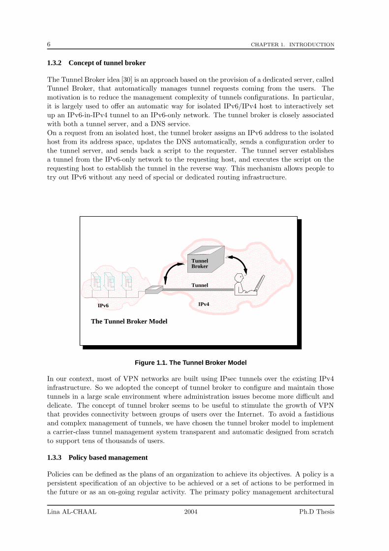
The Tunnel Broker idea [30] is an approach based on the provision of a dedicated server, calledTunnel Broker, that automatically manages tunnel requests coming from the users. Themotivation is to reduce the management complexity of tunnels configurations. In particular,it is largely used to offer an automatic way for isolated IPv6/IPv4 host to interactively setup an IPv6-in-IPv4 tunnel to an IPv6-only network. The tunnel broker is closely associatedwith both a tunnel server, and a DNS service.On a request from an isolated host, the tunnel broker assigns an IPv6 address to the isolatedhost from its address space, updates the DNS automatically, sends a configuration order tothe tunnel server, and sends back a script to the requester. The tunnel server establishesa tunnel from the IPv6-only network to the requesting host, and executes the script on therequesting host to establish the tunnel in the reverse way. This mechanism allows people totry out IPv6 without any need of special or dedicated routing infrastructure.
���������������������������������������������������������������������������������������������������������������������������������������������������������������������������������������������������������������������������������������������������������������������������������������������������������������������������������������������������������������������������������������������������������������������������������������������������������������������������������������������������������������������������������������������������������������������������������������������������������������������������������������������������������������������������������������������������������������������������������������������������������������
���������������������������������������������������������������������������������������������������������������������������������������������������������������������������������������������������������������������������������������������������������������������������������������������������������������������������������������������������������������������������������������������������������������������������������������������������������������������������������������������������������������������������������������������������������������������������������������������������������������������������������������������������������������������������������������������������������������������
������������������������������������������������������������������������������������������������������������������������������������������������������������������������������������������������������������������������������������������������������������������������������������������������������������������������������������������������������������������������������������������������������������������������������������������������������������������������������������������������������������������������������������������������������������������������������������������������������������������������������������������������������������������������������������������������������������������������������������������������������������������������������������������������������������������������������������������������������������������������������������������������������������������������������������������������������������������������������������������������������������������������������������������������������������������������������������������������������������������������������������������������������������������������������������������������������������������������������������������������������������������������������������������������������������������������������������������������������������������������������������������������������������������������������������������������������������������������������������������������������������������������������������������������������������������������������������������������������������������������������������������������������������������������������������������������������������������������������������������������������������������������������������������������������������������������������������������������������������������������������������������������������������������������������������������������������������������������������������������������������������������������������������������������������������������������������������������������������������������������������������������������������������������������������������������������������������������������������
����������������������������������������������������������������������������������������������������������������������������������������������������������������������������������������������������������������������������������������������������������������������������������������������������������������������������������������������������������������������������������������������������������������������������������������������������������������������������������������������������������������������������������������������������������������������������������������������������������������������������������������������������������������������������������������������������������������������������������������������������������������������������������������������������������������������������������������������������������������������������������������������������������������������������������������������������������������������������������������������������������������������������������������������������������������������������������������������������������������������������������������������������������������������������������������������������������������������������������������������������������������������������������������������������������������������������������������������������������������������������������������������������������������������������������������������������������������������������������������������������������������������������������������������������������������������������������������������������������������������������������������������������������������������������������������������������������������������������������������������������������������������������������������������������������������������������������������������������������������������������������������������������������������������������������������������������������������������������������������������������������������������������������������������������������������������������������������������������������������������������������������������������������
The Tunnel Broker Model
TunnelBroker
IPv4 IPv6
Tunnel
Figure 1.1. The Tunnel Broker Model
In our context, most of VPN networks are built using IPsec tunnels over the existing IPv4infrastructure. So we adopted the concept of tunnel broker to configure and maintain thosetunnels in a large scale environment where administration issues become more difficult anddelicate. The concept of tunnel broker seems to be useful to stimulate the growth of VPNthat provides connectivity between groups of users over the Internet. To avoid a fastidiousand complex management of tunnels, we have chosen the tunnel broker model to implementa carrier-class tunnel management system transparent and automatic designed from scratchto support tens of thousands of users.
1.3.3 Policy based management
Policies can be defined as the plans of an organization to achieve its objectives. A policy is apersistent specification of an objective to be achieved or a set of actions to be performed inthe future or as an on-going regular activity. The primary policy management architectural
Lina AL-CHAAL 2004 Ph.D Thesis
1.4. GOALS OF THE THESIS 7
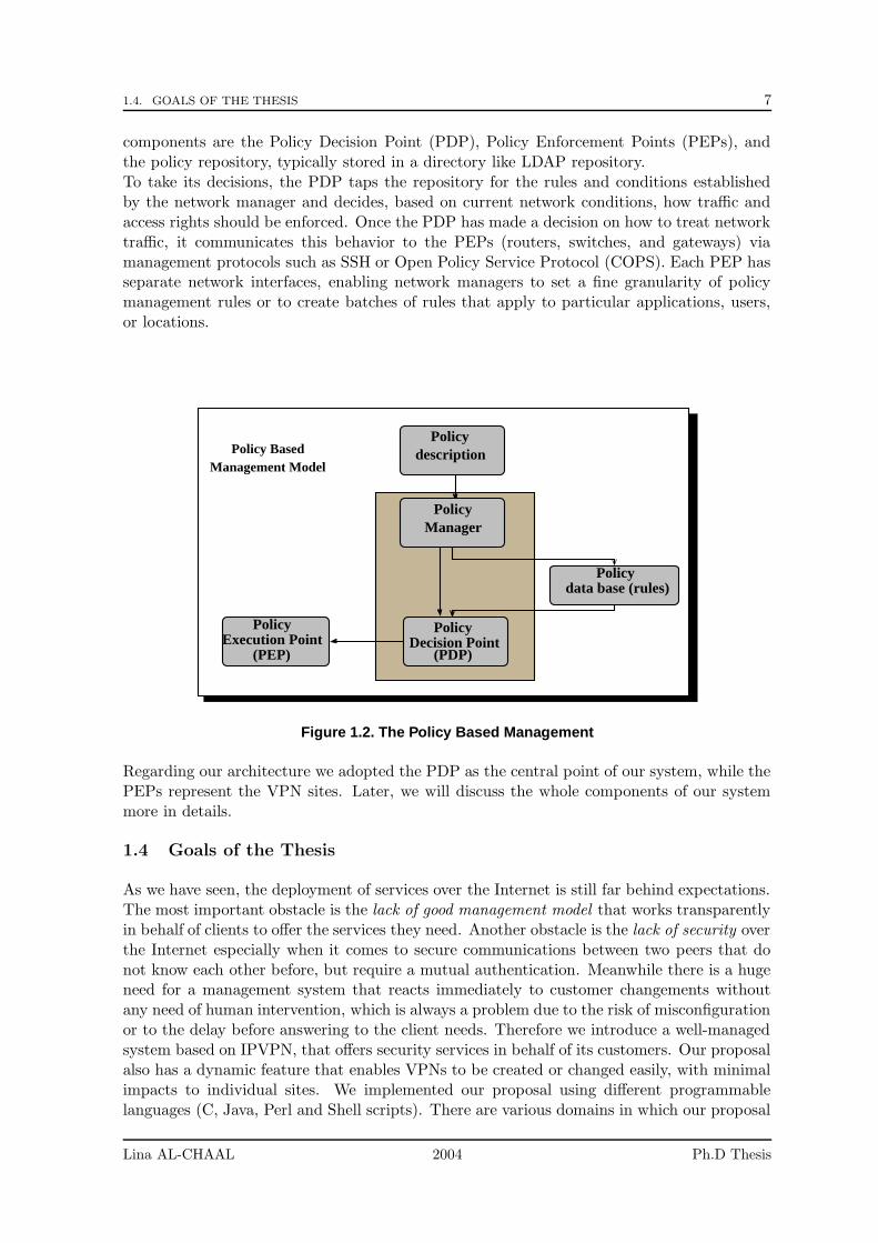
components are the Policy Decision Point (PDP), Policy Enforcement Points (PEPs), andthe policy repository, typically stored in a directory like LDAP repository.To take its decisions, the PDP taps the repository for the rules and conditions establishedby the network manager and decides, based on current network conditions, how traffic andaccess rights should be enforced. Once the PDP has made a decision on how to treat networktraffic, it communicates this behavior to the PEPs (routers, switches, and gateways) viamanagement protocols such as SSH or Open Policy Service Protocol (COPS). Each PEP hasseparate network interfaces, enabling network managers to set a fine granularity of policymanagement rules or to create batches of rules that apply to particular applications, users,or locations.
Policy
Policy
Policy
Policy
Policy
description
Manager
data base (rules)
Decision PointExecution Point(PEP) (PDP)
Management ModelPolicy Based
Figure 1.2. The Policy Based Management
Regarding our architecture we adopted the PDP as the central point of our system, while thePEPs represent the VPN sites. Later, we will discuss the whole components of our systemmore in details.
1.4 Goals of the Thesis
As we have seen, the deployment of services over the Internet is still far behind expectations.The most important obstacle is the lack of good management model that works transparentlyin behalf of clients to offer the services they need. Another obstacle is the lack of security overthe Internet especially when it comes to secure communications between two peers that donot know each other before, but require a mutual authentication. Meanwhile there is a hugeneed for a management system that reacts immediately to customer changements withoutany need of human intervention, which is always a problem due to the risk of misconfigurationor to the delay before answering to the client needs. Therefore we introduce a well-managedsystem based on IPVPN, that offers security services in behalf of its customers. Our proposalalso has a dynamic feature that enables VPNs to be created or changed easily, with minimalimpacts to individual sites. We implemented our proposal using different programmablelanguages (C, Java, Perl and Shell scripts). There are various domains in which our proposal
Lina AL-CHAAL 2004 Ph.D Thesis
8 CHAPTER 1. INTRODUCTION
can be applied, but this thesis will focus on the following two aspects: group communicationservices and web services.
1.5 Organization of the Document
The rest of the document is organized into as follows:
• Chapter 2 introduces and discusses several models for building VPNs. We classifythe models into several categories: based on routing information exchanged betweencustomers equipments and providers equipments (overlay and peer-to-peer VPNs), ordepending on the management’s way of the VPN equipments (CE-based or Networkbased VPNs).
• Chapter 3 describes our dynamic CE-based VPN proposal which is a centralized so-lution, where everything, including clients membership management and topology cre-ation, is under the control of a single Management Operation Point (MOP).
• In chapter 4 we describe how to adapt our proposal to offer group communicationservices. We describe our new protocol, Internet VPN Group Management Protocol(IVGMP), as an alternative to traditional multicast routing protocols, that forwardsmulticast traffic over secure VPN topology.
• In chapter 5, we investigate the use of an application level multicast protocol calledHost Based Multicast (HBM) to build a fully secure and efficient group communicationservice between several sites. We showed that HBM and our VPN approach naturally fitwith one-another and lead to the concept of Virtual Private Routing Network (VPRN).This chapter explains how the scalability can be largely improved by this new proposal.
• In chapter 6, we discuss the use of our proposal to manage and secure web services ina simple and dynamic way that fits well with the dynamic nature of web services. Weshow how there is a mutual need between the VPN technology and the web servicetechnology. And we also discuss some design and performance aspects.
• Chapter 7 focuses on the problem of high availability of CE devices into VPN sites.We show how our proposal and its dynamic aspect play an essential role to rapidlyovercome failure problems and to naturally offer a load balancing when the number ofVPNs to which a VPN site belongs to, increases.
• Finally, we discuss some key points and conclude this thesis in chapter 8.
Lina AL-CHAAL 2004 Ph.D Thesis
Part I
Overview of VPN Technologies andModels
9

Chapter 2
Survey of VPN technologies andtheir Management
Contents
2.1 Introduction . . . . . . . . . . . . . . . . . . . . . . . . . . . . . . . 11
2.2 ISP Network Components Terminology . . . . . . . . . . . . . . . 12
2.3 VPN Technology in the Telecommunication World . . . . . . . . 13
2.3.1 VPN Working Groups . . . . . . . . . . . . . . . . . . . . . . . . . . 13
2.3.2 Tunneling Mechanisms . . . . . . . . . . . . . . . . . . . . . . . . . . 15
2.3.3 IPsec VPN Tunneling Mechanism . . . . . . . . . . . . . . . . . . . . 16
2.3.4 SSL VPN Tunneling Mechanism . . . . . . . . . . . . . . . . . . . . 23
2.3.5 IPsec versus SSL VPN . . . . . . . . . . . . . . . . . . . . . . . . . . 25
2.3.6 Other Tunneling Protocols . . . . . . . . . . . . . . . . . . . . . . . 27
2.3.7 Different Connectivity VPN Models . . . . . . . . . . . . . . . . . . 29
2.4 Various Types of IPVPN Solutions . . . . . . . . . . . . . . . . . . 31
2.4.1 IPVPN definition . . . . . . . . . . . . . . . . . . . . . . . . . . . . . 32
2.4.2 General Classifications of IPVPN Types . . . . . . . . . . . . . . . 32
2.4.3 CE-based IPVPN Details . . . . . . . . . . . . . . . . . . . . . . . . 33
2.4.4 Provider-based VPN Details . . . . . . . . . . . . . . . . . . . . . . . 34
2.5 VPN Management Challenges . . . . . . . . . . . . . . . . . . . . . 38
2.6 Partial Conclusions . . . . . . . . . . . . . . . . . . . . . . . . . . . 41
In this chapter, we introduce the role of the VPN technology in the telecommunication worldas well as the different VPN models that exist. We compare these technologies and highlightin particular the management challenges they raised.
2.1 Introduction
Today’s service providers are experiencing an increasing demand for IP services due to thesuccess of the Internet. More and more companies want to outsource Internet, intranet andextranet services, managed network services, and content-related services such as Web host-ing, mail service, and secure remote access. As a result, the Service Provider’s profitability
11
12 CHAPTER 2. SURVEY OF VPN TECHNOLOGIES AND THEIR MANAGEMENT
in the telecommunication world is defined by their ability to rapidly introduce new servicestailored to the specific needs of their customers.
Fortunately the evolution of telecommunication networks toward the current broadband net-works made feasible the support of those services, at least in terms of offered bandwidth.The main issue that remains is to resolve the deployment, provision and control of networkservices.
Lately in the last decade, service providers have considered the VPN technology that offersthe promising solution to managing network services in a transparent way to clients. ThisVPN technology plays a significant role to achieve management goals and deliver guaranteedlevels of performance, reliability, leading-edge management and monitoring tools. Howeverthe VPN management issues are still in their early stages.
In this chapter, we describe the different VPN technologies currently in use. We comparethem, considering their functionalities and application fields. Then we focus on the VPNmanagement challenges and what we get by applying such technologies from the manage-ment’s viewpoint. Later, in the next chapter, we will introduce our own VPN approach, seehow it compares with other technologies, and the benefits it offers regarding the managementissues.
2.2 ISP Network Components Terminology
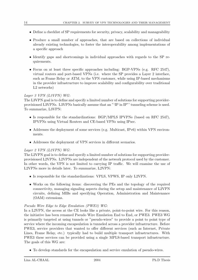
In the remaining of this document, we will use the following definitions [10], that define anInternet Service Providers (ISP)’s network components:
• Internet Service Provider (ISP): the ISP is a company that provides dial-up or directaccess to the Internet for a fee. It is the company that provides the gateway between acustomer and the Internet.
• Service Provider (SP): the SP is a company that generates revenues for the servicesdelivered to their customers over a network, typically the Internet. The price for suchservices must include the actual delivery of the service including accommodations forthe cost of the infrastructure to deliver the service (e.g. hardware, software, data center,labor, IP). Since most of SPs provide connections to the Internet, they are also knownas ISPs.
• Customer Edge/Equipment (CE): the CE device is located at the customer’s side. Ithas an access connection with the provider’s edge router, PE. Note that sometimesin the VPN terminology, we distinguish between two types of customer edge devices:the CE device and the CPE device. In the first case, the CE device is owned by thecustomer, but it is managed by a service provider. On the opposite, the CPE device isboth provided and managed by a service provider. In this document, we will use CEto refer to both types of devices, unless otherwise mentioned.
• Provider Edge (PE): the PE device links several CEs to the provider network. ThePE forwards traffic from CEs to other provider’s routers P, depending on routing in-formation within the PEs. There is routing information for all VPNs used by the CEsconnected to that PE.
• Provider router (P): the P router is located at the provider’s network and used tointerconnect the PE routers. There is no direct connection between a CE and a Prouter.
Lina AL-CHAAL 2004 Ph.D Thesis

2.3. VPN TECHNOLOGY IN THE TELECOMMUNICATION WORLD 13
• Edge Device (ED): the edge device may be either a PE or a CE, depending on theservice demarcation point between the provider and the customer.
���������������������������������������������������������������������������������������������������������������������������������������������������������������������������������������������������������������������������������������������������������������������������������������������������������������������������������������������������������������������������������������������������������������������������������������������������������������������������������������������������������������������������������������������������������������������������������������������������������������������������������������������������������������������������������������������������������������������������������������������������������������������������������������������������������
���������������������������������������������������������������������������������������������������������������������������������������������������������������������������������������������������������������������������������������������������������������������������������������������������������������������������������������������������������������������������������������������������������������������������������������������������������������������������������������������������������������������������������������������������������������������������������������������������������������������������������������������������������������������������������������������������������������������������������������������������������������������������������������������������������
CE
P
PP
P
CECE
Customer site
Customer site
Customer site
Customer site
CE
CEISP core network
ISP network
PE
PE
PE
Figure 2.1. ISP Network and Elements
To avoid ambiguity, we use the term ’client site’ or simply ’site’ to refer to the customernetwork which can range from a simple personal computer (e.g. PC, laptop, PDA or mobilephone) to complex networks settled behind a CE device.
In ISP based VPNs, the category of VPNs that we are the most interested in, a client site isconnected via a Customer Edge (CE) to the ISP core network. The CE is an IP router thatprovides a client access to the ISP network over a data link to one or more Provider Edge(PE) routers. A PE router maintains VPN routing information for each VPN and forwardsthe VPN traffic to a Provider (P) router. This latter could be any router in the ISP networkthat does not attach to CE devices.
2.3 VPN Technology in the Telecommunication World
2.3.1 VPN Working Groups
A few years ago many IETF working groups have defined and specified new VPN solutionsand requirements like L3VPN, L2VPN, PPVPN and PWE3. All working groups addressthe same problem space, the provider provisioned virtual private networking for the endcustomers. They address a wide range of services without creating new protocols, but byproviding new extensions to the existing ones. Here are briefly the goals of the respectiveworking groups:
Provider Provisioned IPVPN (PPVPN) WG :
PPVPN is responsible for defining and specifying a limited number of sets of solutions forsupporting provider-provisioned virtual private networks (PPVPNs). Precisely, the goals ofthis WG are to:
Lina AL-CHAAL 2004 Ph.D Thesis
14 CHAPTER 2. SURVEY OF VPN TECHNOLOGIES AND THEIR MANAGEMENT
• Define a checklist of SP requirements for security, privacy, scalability and manageability
• Produce a small number of approaches, that are based on collections of individualalready existing technologies, to foster the interoperability among implementations ofa specific approach
• Identify gaps and shortcomings in individual approaches with regards to the SP re-quirements.
• Focus on at least three specific approaches including: BGP-VPNs (e.g. RFC 2547),virtual routers and port-based VPNs (i.e. where the SP provides a Layer 2 interface,such as Frame Relay or ATM, to the VPN customer, while using IP-based mechanismsin the provider infrastructure to improve scalability and configurability over traditionalL2 networks)
Layer 3 VPN (L3VPN) WG :
The L3VPN goal is to define and specify a limited number of solutions for supporting provider-provisioned L3VPNs. L3VPNs basically assume that an ”‘IP in IP”’ tunneling scheme is used.To summarize, L3VPN:
• Is responsible for the standardizations: BGP/MPLS IPVPNs (based on RFC 2547),IPVPNs using Virtual Routers and CE-based VPNs using IPsec.
• Addresses the deployment of some services (e.g. Multicast, IPv6) within VPN environ-ments.
• Addresses the deployment of VPN services in different scenarios.
Layer 2 VPN (L2VPN) WG :
The L2VPN goal is to define and specify a limited number of solutions for supporting provider-provisioned L2VPNs. L2VPNs are independent of the network protocol used by the customer.In other words, the VPN is not limited to carrying IP traffic. We will examine the use ofL2VPNs more in details later. To summarize, L2VPN:
• Is responsible for the standardizations: VPLS, VPWS, IP only L2VPN.
• Works on the following items: discovering the PEs and the topology of the requiredconnectivity, managing signaling aspects during the setup and maintenance of L2VPNcircuits, defining MIBs and specifying Operation, Administration and Maintenance(OAM) extensions.
Pseudo Wire Edge to Edge Emulation (PWE3) WG :
In a L2VPN, the access at the CE looks like a private, point-to-point wire. For this reason,the initiative has been renamed Pseudo Wire Emulation End to End, or PWE3. PWE3 WGis primarily targeted at using tunnels or ”pseudo-wires” to provide a point to point type ofservice where the incoming encapsulation is tunneled across a provider infrastructure. BeforePWE3, service providers that wanted to offer different services (such as Internet, PrivateLines, Frame Relay, etc.) typically had to build multiple transport infrastructures. WithPWE3 these services can be provided using a single MPLS-based transport infrastructure.The goals of this WG are:
• To develop standards for the encapsulation and service emulation of pseudo-wires.
Lina AL-CHAAL 2004 Ph.D Thesis
2.3. VPN TECHNOLOGY IN THE TELECOMMUNICATION WORLD 15
• To pursue standardization of the framework and the service-specific techniques forpseudo-wires.
• To define network management information needed for tunnel operation and manage-ment.
• To specify the security mechanisms to be used to protect the control of the pseudo-wires.
The efforts of these working groups have led to the development of a (partly) new set ofconcepts to describe the VPN services offered that we are going to develop in the remainderof this chapter.
2.3.2 Tunneling Mechanisms
Tunneling Definition
The process of transferring data in a VPN for one network over another network is calledTunneling. The data to be transferred can be frames (or packets) of another protocol. Thetunneling protocol encapsulates the frame in an additional header, instead of sending frameas it is produced by an originating node. The additional header is required for providing therouting information to the encapsulated payload to traverse the intermediate internetwork.The encapsulated packets are then routed between tunnel endpoints over the internetwork.The logical path through which the encapsulated packets travel through the internetwork iscalled a tunnel. Once these encapsulated packets reach the destination they are decapsulatedto get the original data.
Briefly, the basic idea behind network tunneling is that you can take non-routable datapackets and encapsulate them inside routable packets for a transmission over the Internet.At the destination the encapsulation is stripped off and the original data enters the privatenetwork as if it had come from a local source.
Tunneling makes the routed network totally transparent to users. Tunnels are used formany services, like multicasting and mobile IP, and has amazing implications for VPNs. Forexample, you can place a packet that uses a protocol not supported on the Internet (e.g.NetBeui) inside an IP packet and send it safely over the Internet. Or you can place a packetthat uses a private (non-routable) IP address inside a packet that uses a globally unique IPaddress to extend a private network over the Internet.
Tunnels can be static or dynamic. Static tunnels are of little use for VPNs, because theyreserve bandwidth even if they are not used. The second type does not require bandwidthreservation since they are set up as needed and torn down when they are no longer needed.
Tunneling Requirements
Tunneling requires three different protocols:
• Carrier protocol: the protocol used by the underlying network where the informationtravels
• Encapsulating protocol (referred later by tunneling protocol): the protocol (GRE,IPsec, SSL, PPTP, L2TP, etc.) that is wrapped around the original data
• Passenger protocol: the original protocol (IPX, NetBeui, IP) being carried
Lina AL-CHAAL 2004 Ph.D Thesis
16 CHAPTER 2. SURVEY OF VPN TECHNOLOGIES AND THEIR MANAGEMENT
Tunneling Protocols
For a tunnel to be established, both the tunnel client and tunnel server must use the sametunneling protocol (or encapsulating protocol), like IPsec, L2TP, or PPTP [53]. Lately, a newkind of VPN, based on the Secure Sockets Layer SSL protocol, has emerged as the leadingsolution for remote access.
The tunneling functionality can be based on:
• Layer 2 tunneling protocol: this corresponds to the data-link layer and uses frames astheir unit of exchange. PPTP and L2TP both operate at this layer and both encapsulatethe payload in a PPP frame to be sent across an internetwork.
• Layer 3 tunneling protocol: this corresponds to the network layer and uses packets. TheIPsec tunnel mode operates at this layer and encapsulates the packets in an additionalheader before sending them across an IP network.
• Layer 5 protocol: this corresponds to the session layer. SSL is a higher-layer securityprotocol that sits close to the application. It uses a public key to encrypt data that istransfered over the SSL connection.
Here are the descriptions of the most current tunneling protocols in use:
2.3.3 IPsec VPN Tunneling Mechanism
IPsec Definition
The Internet Protocol Security (IPsec) provides several mechanisms that aim at securing traf-fic on the network layer. It is a set of IETF open standards that provides cryptographic-basedprotection mechanisms for IP packets [49]. IPsec has the advantages of offering advancedcryptographic services and proves to be the best security protocol for LAN-to-LAN VPNs,while other security protocols work better for Host-to-Host connections [37]. Besides IPsecis now well known and integrated in many operating systems (e.g. FreeS/Wan for the LinuxOS [36]).
IPsec Communication Channels
An IPsec VPN generally consists of two communication channels between the endpoint hosts:
• a key-exchange channel over which authentication and encryption key information ispassed. The key-exchange channel is a classical UDP connection to and from port 500;and
• one or more data channel(s) over which private traffic is carried. The data channelscarrying the traffic between the client and server use IP protocol number 50 (ESP).
IPsec Modes: Transport and Tunnel
IPsec supports two encryption modes: Transport and Tunnel. Transport mode encryptsonly the data portion (payload) of each packet, but leaves the header untouched. The moresecure Tunnel mode encrypts both the header and the payload. At the receiving side, anIPsec-compliant device decrypts each packet.
IPsec offers the following security features:
Lina AL-CHAAL 2004 Ph.D Thesis
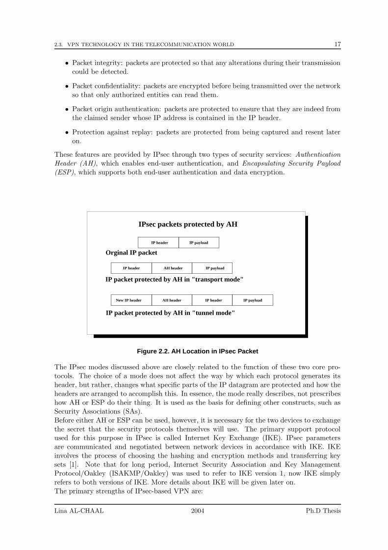
2.3. VPN TECHNOLOGY IN THE TELECOMMUNICATION WORLD 17
• Packet integrity: packets are protected so that any alterations during their transmissioncould be detected.
• Packet confidentiality: packets are encrypted before being transmitted over the networkso that only authorized entities can read them.
• Packet origin authentication: packets are protected to ensure that they are indeed fromthe claimed sender whose IP address is contained in the IP header.
• Protection against replay: packets are protected from being captured and resent lateron.
These features are provided by IPsec through two types of security services: AuthenticationHeader (AH), which enables end-user authentication, and Encapsulating Security Payload(ESP), which supports both end-user authentication and data encryption.
IPsec packets protected by AH
IP payload
IP payload
IP header
IP header AH header
IP payloadIP headerAH headerNew IP header
IP packet protected by AH in "tunnel mode"
IP packet protected by AH in "transport mode"
Orginal IP packet
Figure 2.2. AH Location in IPsec Packet
The IPsec modes discussed above are closely related to the function of these two core pro-tocols. The choice of a mode does not affect the way by which each protocol generates itsheader, but rather, changes what specific parts of the IP datagram are protected and how theheaders are arranged to accomplish this. In essence, the mode really describes, not prescribeshow AH or ESP do their thing. It is used as the basis for defining other constructs, such asSecurity Associations (SAs).Before either AH or ESP can be used, however, it is necessary for the two devices to exchangethe secret that the security protocols themselves will use. The primary support protocolused for this purpose in IPsec is called Internet Key Exchange (IKE). IPsec parametersare communicated and negotiated between network devices in accordance with IKE. IKEinvolves the process of choosing the hashing and encryption methods and transferring keysets [1]. Note that for long period, Internet Security Association and Key ManagementProtocol/Oakley (ISAKMP/Oakley) was used to refer to IKE version 1, now IKE simplyrefers to both versions of IKE. More details about IKE will be given later on.The primary strengths of IPsec-based VPN are:
Lina AL-CHAAL 2004 Ph.D Thesis
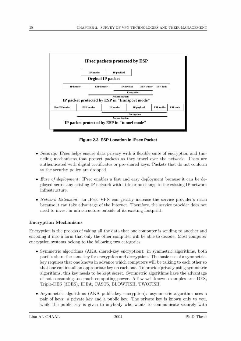
18 CHAPTER 2. SURVEY OF VPN TECHNOLOGIES AND THEIR MANAGEMENT
IP payloadIP headerNew IP header ESP header ESP trailer ESP auth
IP payloadIP header ESP header ESP trailer ESP auth
IP payloadIP header
IPsec packets protected by ESP
Encryption
IP packet protected by ESP in "transport mode"Authentication
Encryption
Authentication
IP packet protected by ESP in "tunnel mode"
Orginal IP packet
Figure 2.3. ESP Location in IPsec Packet
• Security : IPsec helps ensure data privacy with a flexible suite of encryption and tun-neling mechanisms that protect packets as they travel over the network. Users areauthenticated with digital certificates or pre-shared keys. Packets that do not conformto the security policy are dropped.
• Ease of deployment : IPsec enables a fast and easy deployment because it can be de-ployed across any existing IP network with little or no change to the existing IP networkinfrastructure.
• Network Extension: an IPsec VPN can greatly increase the service provider’s reachbecause it can take advantage of the Internet. Therefore, the service provider does notneed to invest in infrastructure outside of its existing footprint.
Encryption Mechanisms
Encryption is the process of taking all the data that one computer is sending to another andencoding it into a form that only the other computer will be able to decode. Most computerencryption systems belong to the following two categories:
• Symmetric algorithms (AKA shared-key encryption): in symmetric algorithms, bothparties share the same key for encryption and decryption. The basic use of a symmetric-key requires that one knows in advance which computers will be talking to each other sothat one can install an appropriate key on each one. To provide privacy using symmetricalgorithms, this key needs to be kept secret. Symmetric algorithms have the advantageof not consuming too much computing power. A few well-known examples are: DES,Triple-DES (3DES), IDEA, CAST5, BLOWFISH, TWOFISH.
• Asymmetric algorithms (AKA public-key encryption): asymmetric algorithm uses apair of keys: a private key and a public key. The private key is known only to you,while the public key is given to anybody who wants to communicate securely with
Lina AL-CHAAL 2004 Ph.D Thesis
2.3. VPN TECHNOLOGY IN THE TELECOMMUNICATION WORLD 19
you. Most encryption algorithms use a public key to encrypt data. If the senderwants to send an encrypted message to the receiver, the sender would use the receiver’spublic key to encrypt the data. When the receiver gets the encrypted message, thereceiver would use his or her private key to decrypt the message. The private key can’tbe reconstructed from the public key. The idea of asymmetric algorithms was firstpublished 1976 by Diffie and Hellmann. As the private key does not have to be shared,the risk of getting known is much smaller. Every user only needs to keep one secret keyand a collection of public keys that only need to be protected against being changed.While with symmetric keys, every pair of users would need to have an own shared secretkey. Well-known asymmetric algorithms are RSA, DSA, ELGAMAL.
Asymmetric algorithms seem to be ideally suited for real-world use. However, asymmetricalgorithms are much slower than symmetric ones. Therefore, in many applications, a com-bination of both is being used. The asymmetric keys are used for authentication and afterthis has been successfully done, one or more symmetric keys are generated and exchangedusing the asymmetric encryption. For instance, the sending computer can encrypt the docu-ment with a symmetric key, and then encrypt the symmetric key with the public key of thereceiving computer. The receiving computer then uses its private key to decode the symmet-ric key, and then uses the symmetric key to decode the document. The sending computerinsures that his message will be only seen by the computer who only owns the private key,without requiring that a secret key be exchanged beforehand. This way the advantages ofboth algorithms can be used. Typical examples are the RSA/IDEA combination of PGP2 orthe DSA/BLOWFISH used by GnuPG.
Internet Key Exchange IKE
IKE provides a secure method of exchanging keys and negotiating protocols and encryptionalgorithms to use. The information negotiated IKE is stored in a Security Association(SA).The SA is like a contract laying out the rules of a connection for the duration of the SA.It describes how two or more entities will use security services to communicate securely.An SA is assigned a 32-bit number that, when used in conjunction with the destination IPaddress, uniquely identifies the SA. This number is called the Security Parameters Indexor SPI. Briefly IKE: (1) creates the first secure and authenticated channel between twocommunicating entities (IKE SA). (2) creates and manages child SAs (IPSEC SA).
To tie this all together, let’s look at an example. User A wants to send data to User B.User A’s router (router A) has a security policy applied with a rule that says all traffic toUser B needs to be encrypted. User B’s router (router B) will be the other end of an IPsectunnel. Router A checks to see if an IPsec SA exists between itself and router B. If no SAexists, router A requests an IPsec SA from IKE. If an IKE SA exists, an IPsec SA is issued.If an IKE SA does not exist, one has to be negotiated first, with the routers exchanginginformation signed by a third-party CA that both routers trust. Once the IKE SA is agreedupon by the routers, an IPsec SA can be issued, and secure, encrypted communications canbegin. This process is transparent to both User A and User B.
To clarify the things, let’s go through the steps for setting up an IPsec connection. Basically,the steps are as follows: Set up an IKE SA. Agree upon the terms of communication andencryption algorithm. Create an IPsec SA. Start sending data. Once the IPsec client ona IPsec peer gets any interesting traffic to treat, it checks if any secure channel is alreadyestablished to the traffic destination. If not the IPsec client starts negotiating an IKE phase1 exchange. The main purpose of IKE Phase 1 is to authenticate the IPsec peers and to set
Lina AL-CHAAL 2004 Ph.D Thesis
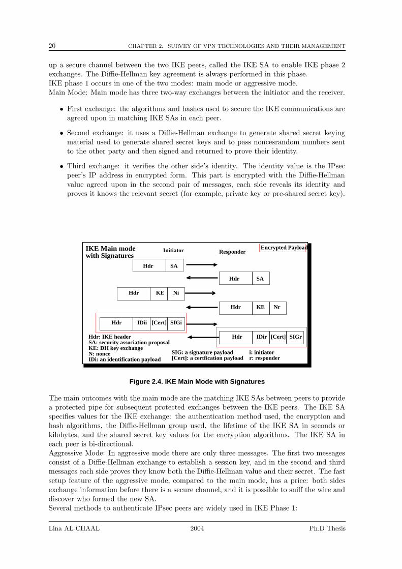
20 CHAPTER 2. SURVEY OF VPN TECHNOLOGIES AND THEIR MANAGEMENT
up a secure channel between the two IKE peers, called the IKE SA to enable IKE phase 2exchanges. The Diffie-Hellman key agreement is always performed in this phase.IKE phase 1 occurs in one of the two modes: main mode or aggressive mode.Main Mode: Main mode has three two-way exchanges between the initiator and the receiver.
• First exchange: the algorithms and hashes used to secure the IKE communications areagreed upon in matching IKE SAs in each peer.
• Second exchange: it uses a Diffie-Hellman exchange to generate shared secret keyingmaterial used to generate shared secret keys and to pass noncesrandom numbers sentto the other party and then signed and returned to prove their identity.
• Third exchange: it verifies the other side’s identity. The identity value is the IPsecpeer’s IP address in encrypted form. This part is encrypted with the Diffie-Hellmanvalue agreed upon in the second pair of messages, each side reveals its identity andproves it knows the relevant secret (for example, private key or pre-shared secret key).
Hdr [Cert]IDii SIGi
Hdr KE
SAHdr
Hdr [Cert] SIGrIDir
Hdr KE Nr
SAHdr
Hdr: IKE headerSA: security association proposalKE: DH key exchange
Ni
N: nonceIDi: an identification payload
Initiator ResponderIKE Main modewith Signatures
r: responderSIG: a signature payload[Cert]: a certfication payload
i: initiator
Encrypted Payload
Figure 2.4. IKE Main Mode with Signatures
The main outcomes with the main mode are the matching IKE SAs between peers to providea protected pipe for subsequent protected exchanges between the IKE peers. The IKE SAspecifies values for the IKE exchange: the authentication method used, the encryption andhash algorithms, the Diffie-Hellman group used, the lifetime of the IKE SA in seconds orkilobytes, and the shared secret key values for the encryption algorithms. The IKE SA ineach peer is bi-directional.Aggressive Mode: In aggressive mode there are only three messages. The first two messagesconsist of a Diffie-Hellman exchange to establish a session key, and in the second and thirdmessages each side proves they know both the Diffie-Hellman value and their secret. The fastsetup feature of the aggressive mode, compared to the main mode, has a price: both sidesexchange information before there is a secure channel, and it is possible to sniff the wire anddiscover who formed the new SA.Several methods to authenticate IPsec peers are widely used in IKE Phase 1:
Lina AL-CHAAL 2004 Ph.D Thesis
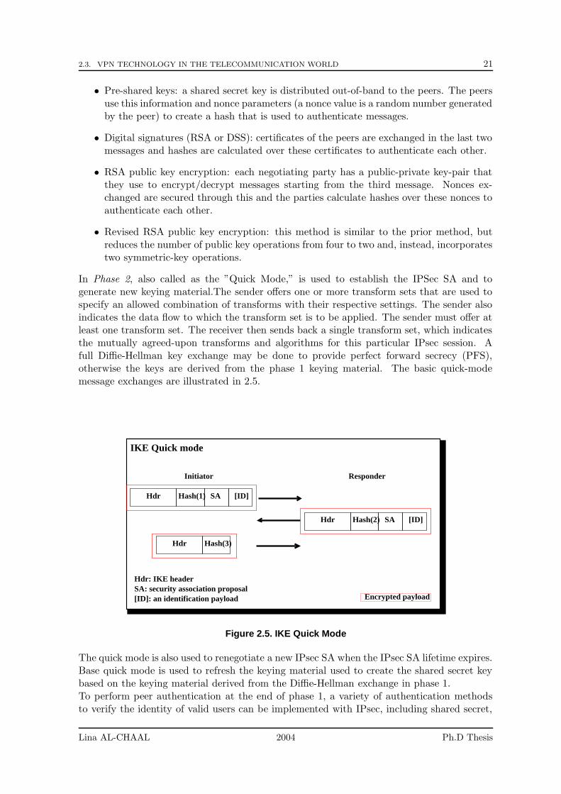
2.3. VPN TECHNOLOGY IN THE TELECOMMUNICATION WORLD 21
• Pre-shared keys: a shared secret key is distributed out-of-band to the peers. The peersuse this information and nonce parameters (a nonce value is a random number generatedby the peer) to create a hash that is used to authenticate messages.
• Digital signatures (RSA or DSS): certificates of the peers are exchanged in the last twomessages and hashes are calculated over these certificates to authenticate each other.
• RSA public key encryption: each negotiating party has a public-private key-pair thatthey use to encrypt/decrypt messages starting from the third message. Nonces ex-changed are secured through this and the parties calculate hashes over these nonces toauthenticate each other.
• Revised RSA public key encryption: this method is similar to the prior method, butreduces the number of public key operations from four to two and, instead, incorporatestwo symmetric-key operations.
In Phase 2, also called as the ”Quick Mode,” is used to establish the IPSec SA and togenerate new keying material.The sender offers one or more transform sets that are used tospecify an allowed combination of transforms with their respective settings. The sender alsoindicates the data flow to which the transform set is to be applied. The sender must offer atleast one transform set. The receiver then sends back a single transform set, which indicatesthe mutually agreed-upon transforms and algorithms for this particular IPsec session. Afull Diffie-Hellman key exchange may be done to provide perfect forward secrecy (PFS),otherwise the keys are derived from the phase 1 keying material. The basic quick-modemessage exchanges are illustrated in 2.5.
Hdr Hash(1) SA [ID]
Encrypted payload
IKE Quick mode
Initiator Responder
Hdr
Hdr SA [ID]Hash(2)
SA: security association proposal[ID]: an identification payload
Hdr: IKE header
Hash(3)
Figure 2.5. IKE Quick Mode
The quick mode is also used to renegotiate a new IPsec SA when the IPsec SA lifetime expires.Base quick mode is used to refresh the keying material used to create the shared secret keybased on the keying material derived from the Diffie-Hellman exchange in phase 1.To perform peer authentication at the end of phase 1, a variety of authentication methodsto verify the identity of valid users can be implemented with IPsec, including shared secret,
Lina AL-CHAAL 2004 Ph.D Thesis
22 CHAPTER 2. SURVEY OF VPN TECHNOLOGIES AND THEIR MANAGEMENT
token cards, and digital certificates. For a large extranet implementation, the easiest methodis Public Key Infrastructure (PKI) using digital certificates.
Certificate Authorities and Digital Certificates
The key exchange can get quite complicated and the distribution of keys in a public keyscheme requires some trust. If the infrastructure is untrusted and control is questionable(such as on the Internet), distribution of keys is troublesome.
In fact, several mechanisms exist to verify whether the public key that the sender gave thereceiver actually belongs to the sender and was not obtained elsewhere.
Before investigating the Certificate Authority (CA) which is the most powerful insurancemechanism used to ensure the legitimacy of public keys, let’s review the following definitions:
• Electronic Signatures are data attached to other data for authentication purposes.
• Digital Signatures are electronic signatures linked to the signed data in a way thattampering is noticed and that the sender can be identified unequivocally. To create adigital signature, a transmitter creates a hash of the message and then uses an exclu-sively transmitter-owned private key to encrypt the hash. This is the digital signatureand it is attached to the real message. The private key has a matching public key thatthe receiver can use to verify the signature. The receiver uses the same hash functionto create a hash of the real message, and then takes the public key to the transmitter,decrypts the digital signature, and compares hashes. A trustworthy institution (i.e., aTrust Center or a Certificate Authority) assigns this pair of keys to a particular person.
• Digital Certificate is simply a collection of information to which a digital signature isattached. This information contains:
– Information of the entity (person, company, or so on) whose certificate it is. Thisentity is referred to as the certificate subject, or owner. These information includethe following attributes (or a subset): the entity’s name, organizational unit, or-ganization, city or locality, state or province, and country code.
– The owner’s public key.
– The digital signature of the CA or the issuer. This is used to vouch for the factthat the enclosed public key is the actual public key of the owner.
– Information for the CA or the issuer.
The standard digital certificate format is defined in the X.509 specification.
VeriSign, Entrust, and Netscape are examples of companies that are providing digital cer-tificates. A client registers with a certificate authority; after the CA verifies the customer’scredentials, a certificate is issued. A CA performs the following main functions:
1. It issues a pair of keys for a customer guaranteeing the uniqueness of the pair.
2. It certifies a customer’s public key.
3. It publishes a customer’s certificate.
4. It Issues Certificate Revocation Lists (CRLs).
Lina AL-CHAAL 2004 Ph.D Thesis

2.3. VPN TECHNOLOGY IN THE TELECOMMUNICATION WORLD 23
The CA acts as the agent of trust in the key management system the Public Key Infras-tructure (PKI). The PKI uses to secure exchange of digital signatures, encrypted documents,authentication and authorization of many communication partners in open networks. A PKIcan be used to manage IKE’s authentication keys, but IKE does not specify its interactionwith a PKI. In addition to the CA, the PKI has three other parts: The Registration Au-thority (RA) which is responsible for recording and verifying all information the CA needs,The directory service which publishes certificates and a CRL or make an on-line certificateavailable and finally a special service the Timestamping that confirms the receipt of digitaldocuments at a specific point in time.
2.3.4 SSL VPN Tunneling Mechanism
Secure Sockets Layer (SSL) VPNs rely on a commonly used protocol for managing the securityof data transmissions on the Internet. SSL VPNs use a program layer located between theInternet’s Hypertext Transfer Protocol (HTTP) and TCP protocols for communication [71][12].
SSL VPNs have many benefits:
• They are easy to deploy and easy to maintain.
• They need fewer firewalls changes since SSL firewalls are generally kept open.
• SSL VPNs are the ideal solution for corporations whose employees are often on the go,since they can be extended to reach remote accesses.
• SSL support is included with most web browsers (Mozilla, Netscape, IE), as well aswith most web server products.
• SSL VPNs deliver user-level authentication, ensuring that only authorized users haveaccess to the specific resources as allowed by the security policy in use. SSL uses thepublic-and-private key encryption system from RSA, which also includes the use of adigital certificate.
The essential limit of SSL VPN is that it provides access only to web applications, while itfails to address access services to other client/server applications.We can distinguish three types of SSL VPN technologies;
• Application layer proxies: this is the simplest form of SSL VPNs because they relyon the SSL functionality used by existing applications. Because of this, applicationlayer proxies have the least application support. Generally, they only support Emailand Web-based traffic. To use email, your administrator would configure the SSLfunctionality in your email client and proxy all email traffic via the gateway. One ofthe advantages of application layer proxies is that they do not have to get a specialprogram or support, and operate with nearly all operating systems and web browsers.
• Protocol redirector : the protocol redirector approach is more flexible than the applica-tion layer proxies, but it requires a kind of program or support. Protocol redirectorswork by downloading a mini support from the gateway, which installs locally and redi-rects traffic. For instance, if a connection is made from an application that does notuse SSL, the connection is captured below the IP layer and encapsulated within anSSL tunnel. Once the traffic reaches the SSL gateway, it is decrypted and then proxiedto the original destination. This would appear to be an ideal mechanism, because all
Lina AL-CHAAL 2004 Ph.D Thesis
24 CHAPTER 2. SURVEY OF VPN TECHNOLOGIES AND THEIR MANAGEMENT
normal applications work with minimal intervention for the user. The reality though isslightly different. The only realistic way the support can capture the traffic on the waythrough the IP stack is to redirect traffic based on name resolution to a local resource.Once the port redirector is enabled, the name of a remote site will be forced to connectto localhost through the use of a host file. This means the mini support must have theability to write changes to the hosts file, which in a hardened corporate desktop maynot always be possible. Also, in most implementations some administrative permissionis required on the local desktop to install the mini support. The main advantage of theprotocol redirection system is that it can support any application that works over fixedTCP or UDP ports (and in some implementations, applications using dynamic portsmay be supported, like MS Outlook).
• Remote control VPN : this category is sometimes merged with the first category, ”application-layer VPN”, but we prefer to distinguish them. Remote control VPNs are the mostflexible form of SSL based VPN, but they also have the highest overhead. They workby enhancing a remote control protocol like Windows Terminal Services, and by addingSSL VPN functionality and Web Browser support. This means that any applicationcan be added to the SSL VPN by adding the application to the remote control desktop.As a stand-alone application, this has serious limitations, because applications thatreside on the local desktop cannot be used directly. This is why most remote controlVPNs are partnered with other SSL VPN technologies. On the positive side though,they can offer features like the ability to read and update a document held centrallywithout ever having to download the entire document. When traveling and using VPNover low speed connections, or when the connection quality is poor this may be very ad-vantageous (because connections are restarted without loosing any work). The centralelement of a remote control VPN is the application-layer proxy, typically provided in theform of a dedicated VPN appliance. The proxy offers a single point of administrationwhile acting as a sentinel to the private network behind the firewall. A remote controlVPN acts as an intermediary between remote client requests and server-based applica-tions. It terminates incoming connections from remote users at the application layer,processes the data and then translates the data to the appropriate backend applicationprotocol, like:
– Remote Desktop Protocol (RDP) for Windows applications residing on WindowsTerminal Servers
– X.11 over SSH for UNIX or Linux applications
– 3270 over Telnet for mainframe and AS/400 applications
– HTTP/HTTPS for web servers.
During this termination gap, the VPN appliance analyzes application information, ap-plies security policy and serves as a gatekeeper between the Internet and the privatenetwork. A remote control VPN runs client and server versions of an application on asingle server, eliminating the need for a client on the remote PC.
For example, for Windows applications, a remote user launches a browser and entersthe URL of the remote control VPN appliance. SSL is used to encrypt all data from theuser’s browser to the remote control VPN. SSL provides strong security, and most Webbrowsers incorporate it. The remote control VPN enforces policy during the terminationgap by polling external authentication and policy servers, such as Active Directory orLightweight Directory Access Protocol, to certify user identities and authorize specific
Lina AL-CHAAL 2004 Ph.D Thesis
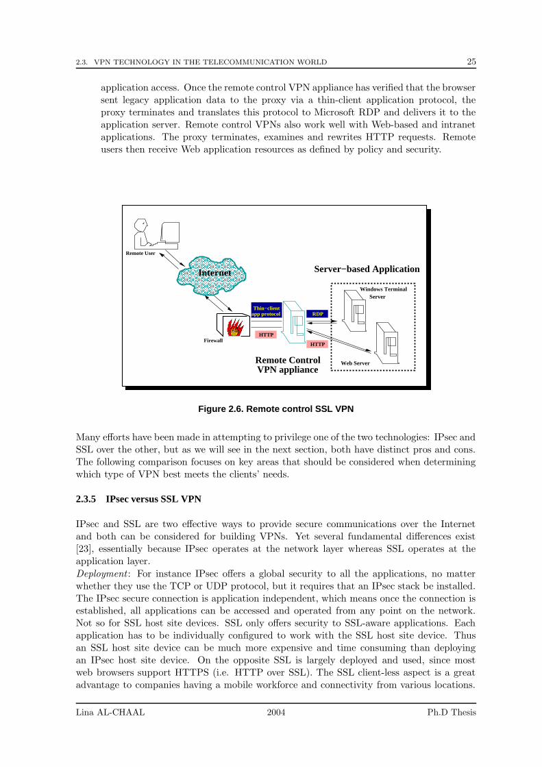
2.3. VPN TECHNOLOGY IN THE TELECOMMUNICATION WORLD 25
application access. Once the remote control VPN appliance has verified that the browsersent legacy application data to the proxy via a thin-client application protocol, theproxy terminates and translates this protocol to Microsoft RDP and delivers it to theapplication server. Remote control VPNs also work well with Web-based and intranetapplications. The proxy terminates, examines and rewrites HTTP requests. Remoteusers then receive Web application resources as defined by policy and security.
������������������������������������������
������������������������������������������
���������������
���������������
�����������������������������������������������������������������������������������������������������������������������������������������������������������������������������������������������������������������������������������������������������������������������������������������������������������
�����������������������������������������������������������������������������������������������������������������������������������������������������������������������������������������������������������������������������������������������������������������������������������������������������������
Remote User
Internet
Thin−clientapp protocol
HTTP
HTTP
RDP
Remote ControlVPN appliance
Windows TerminalServer
Web Server
Server−based Application
Firewall
Figure 2.6. Remote control SSL VPN
Many efforts have been made in attempting to privilege one of the two technologies: IPsec andSSL over the other, but as we will see in the next section, both have distinct pros and cons.The following comparison focuses on key areas that should be considered when determiningwhich type of VPN best meets the clients’ needs.
2.3.5 IPsec versus SSL VPN
IPsec and SSL are two effective ways to provide secure communications over the Internetand both can be considered for building VPNs. Yet several fundamental differences exist[23], essentially because IPsec operates at the network layer whereas SSL operates at theapplication layer.
Deployment : For instance IPsec offers a global security to all the applications, no matterwhether they use the TCP or UDP protocol, but it requires that an IPsec stack be installed.The IPsec secure connection is application independent, which means once the connection isestablished, all applications can be accessed and operated from any point on the network.Not so for SSL host site devices. SSL only offers security to SSL-aware applications. Eachapplication has to be individually configured to work with the SSL host site device. Thusan SSL host site device can be much more expensive and time consuming than deployingan IPsec host site device. On the opposite SSL is largely deployed and used, since mostweb browsers support HTTPS (i.e. HTTP over SSL). The SSL client-less aspect is a greatadvantage to companies having a mobile workforce and connectivity from various locations.
Lina AL-CHAAL 2004 Ph.D Thesis
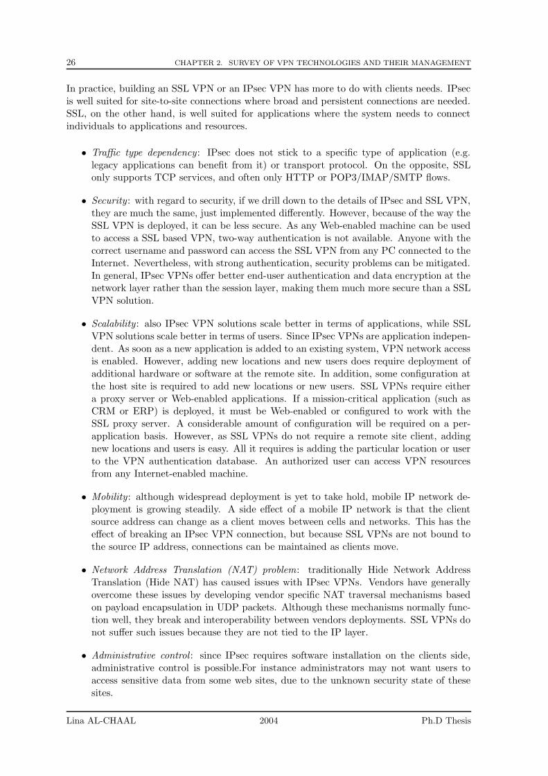
26 CHAPTER 2. SURVEY OF VPN TECHNOLOGIES AND THEIR MANAGEMENT
In practice, building an SSL VPN or an IPsec VPN has more to do with clients needs. IPsecis well suited for site-to-site connections where broad and persistent connections are needed.SSL, on the other hand, is well suited for applications where the system needs to connectindividuals to applications and resources.
• Traffic type dependency : IPsec does not stick to a specific type of application (e.g.legacy applications can benefit from it) or transport protocol. On the opposite, SSLonly supports TCP services, and often only HTTP or POP3/IMAP/SMTP flows.
• Security : with regard to security, if we drill down to the details of IPsec and SSL VPN,they are much the same, just implemented differently. However, because of the way theSSL VPN is deployed, it can be less secure. As any Web-enabled machine can be usedto access a SSL based VPN, two-way authentication is not available. Anyone with thecorrect username and password can access the SSL VPN from any PC connected to theInternet. Nevertheless, with strong authentication, security problems can be mitigated.In general, IPsec VPNs offer better end-user authentication and data encryption at thenetwork layer rather than the session layer, making them much more secure than a SSLVPN solution.
• Scalability : also IPsec VPN solutions scale better in terms of applications, while SSLVPN solutions scale better in terms of users. Since IPsec VPNs are application indepen-dent. As soon as a new application is added to an existing system, VPN network accessis enabled. However, adding new locations and new users does require deployment ofadditional hardware or software at the remote site. In addition, some configuration atthe host site is required to add new locations or new users. SSL VPNs require eithera proxy server or Web-enabled applications. If a mission-critical application (such asCRM or ERP) is deployed, it must be Web-enabled or configured to work with theSSL proxy server. A considerable amount of configuration will be required on a per-application basis. However, as SSL VPNs do not require a remote site client, addingnew locations and users is easy. All it requires is adding the particular location or userto the VPN authentication database. An authorized user can access VPN resourcesfrom any Internet-enabled machine.
• Mobility : although widespread deployment is yet to take hold, mobile IP network de-ployment is growing steadily. A side effect of a mobile IP network is that the clientsource address can change as a client moves between cells and networks. This has theeffect of breaking an IPsec VPN connection, but because SSL VPNs are not bound tothe source IP address, connections can be maintained as clients move.
• Network Address Translation (NAT) problem: traditionally Hide Network AddressTranslation (Hide NAT) has caused issues with IPsec VPNs. Vendors have generallyovercome these issues by developing vendor specific NAT traversal mechanisms basedon payload encapsulation in UDP packets. Although these mechanisms normally func-tion well, they break and interoperability between vendors deployments. SSL VPNs donot suffer such issues because they are not tied to the IP layer.
• Administrative control : since IPsec requires software installation on the clients side,administrative control is possible.For instance administrators may not want users toaccess sensitive data from some web sites, due to the unknown security state of thesesites.
Lina AL-CHAAL 2004 Ph.D Thesis
2.3. VPN TECHNOLOGY IN THE TELECOMMUNICATION WORLD 27
• Header overheads and performances: SSL VPNs offer some performance advantagesover IPsec VPNs when considering the header overhead. If we ignore the setup opera-tions, the header overhead of IPsec on a packet is between 50 and 57 bytes (includingthe new IP header, the ESP header and the trailers), representing a 10% increase fora 500 byte packet. On the opposite, SSL VPNs add only 5 bytes of data to eachpacket, just a 1% increase with 500 byte packets. Of course, the setup operations can-not be ignored, but these are roughly similar in size for IPsec and SSL connections.Also, because SSL VPNs work at a higher layer, they suffer much less from the packetfragmentation issues normally associated with IPsec VPNs. Finally, SSL has built incompression mechanisms, not IPsec.
Neither technology is the perfect solution, it depends on the type of access required by clientsas well as other criteria, such as performance, manageability, or ease of integration[11]. Inspite of their differences, both technologies can:
• determine if an information needs to be encrypted before going through the Internet,
• negotiate encryption keys, including authentication of each side,
• encrypt data and send it to the destination, and
• check data integrity to determine if data has been tampered while in transit.
Therefore both technologies can be used in a VPN environment and we consider both IPsecand SSL based VPNs in our VPN web service architecture proposal.
2.3.6 Other Tunneling Protocols
Since we are only interested in the two tunneling protocols discussed above, we do not detailthe other possibilities, but only give a quick glance on them.
• GRE: the Generic Routing Encapsulation protocol (GRE), described in RFC1701, al-lows an arbitrary network protocol A to be transmitted over any arbitrary networkprotocol B, by encapsulating the packets of A within GRE packets, which in turn arecontained within packets of B.
• PPTP: the Point to Point Tunneling Protocol (PPTP) consists of two communicationchannels between the client and server:
– a control channel where link-management information is sent. This is in fact astandard TCP connection to port 1723 (server).
– a data channel over which (possibly encrypted) private network traffic is carried.This data channel uses a dedicated IP protocol number, 47, reserved to GRE.
Currently PPTP is the most common VPN connection method in a Windows environ-ment. Microsoft’s implementation of PPTP uses the Point-to-Point Protocol (PPP)to initially encapsulate the data, then encrypts this with Microsoft’s Point-to-PointEncryption (MPPE).
Authentication is provided by Windows’ built in dial-up authentication protocols; MS-CHAP, MS-CHAP v2 (Microsoft Challenge Handshake Authentication Protocol) andEAP (Extensible Authentication Protocol). These protocols provide a means of authen-ticating both the client and the VPN server by means of a user name and password,
Lina AL-CHAAL 2004 Ph.D Thesis
28 CHAPTER 2. SURVEY OF VPN TECHNOLOGIES AND THEIR MANAGEMENT
IPheader
Data linkheader
Data linktrailer
headerIP
headerData link
headerGRE PPP
headerPPP
payload
EncryptedData link
trailer
header messageTCP
PPTP data packet
PPTP control frame
PPTP control and data frames
PPTPcontrol
Figure 2.7. PPTP control and data frames
in the case of MS-CHAP, or a computer certificate or smart card in the case of EAP.Once data is encrypted, it is encapsulated again, this time inside a GRE packet, whichprovides the information necessary to transmit PPP information over the Internet. Wenow have the original data encrypted and enclosed within a PPP data packet, thenfurther encapsulated within a GRE packet for transmission across the Internet. PPTPuses the separate, unencrypted control channel to carry the commands used to open,close and maintain the connection.
• L2TP: this new VPN technology, Layer 2 Tunneling Protocol (L2TP), combines someof the features of Microsoft’s PPTP with Cisco’s L2F. In the Windows implementation,L2TP wraps the whole thing up in Microsoft’s version of the IPsec encryption andauthentication protocols.
IPsec is used both to encrypt both the control and the data packets via the exchangeof a security certificate or a pre-shared key. Standard PPP authentication (MS-CHAP,EAP) is still used to validate the user with a user name and password combination.Using IPsec authentication provides an extra level of security by assuring that themachines at both ends of the VPN are known and trusted. In theory L2TP could beused without IPsec, but in practice it is not very feasible since it uses no other form ofencryption.
L2TP/IPsec differs considerably from PPTP. L2TP VPNs do not use a separate, unen-crypted control channel to send control information as PPTP does. Instead of that, thecontrol information needed to start, maintain and close a VPN tunnel is sent throughthe same port, like data, using L2TP control data instead of the PPP encapsulateddata.
Data is first encapsulated in a PPP packet similarly to the former method, and a PPPheader added. An L2TP header containing the necessary information to convey the datathrough the Internet is next, followed by a UDP header. UDP, part of the TCP/IPsuite of protocols, is the protocol L2TP VPNs use to transmit and receive data through
Lina AL-CHAAL 2004 Ph.D Thesis
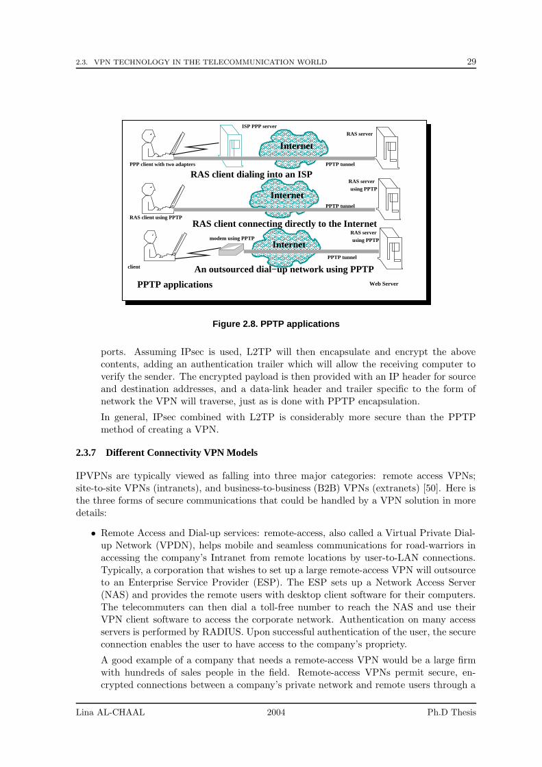
2.3. VPN TECHNOLOGY IN THE TELECOMMUNICATION WORLD 29
�����������������������������������������������������������������������������������������������������������������������������������������������������������������������������������������������������������������������������������������������������������������������������������������������������������
�����������������������������������������������������������������������������������������������������������������������������������������������������������������������������������������������������������������������������������������������������������������������������������������������������������
Internet
����������������������������������������������������������������������������������������������������������������������������������������������������������������������������������������������������������������������������������������������������������������������������������������������������������������������������������
����������������������������������������������������������������������������������������������������������������������������������������������������������������������������������������������������������������������������������������������������������������������������������������������������������������������������������
Internet
�������������������������������������������������������������������������������������������������������������������������������������������������������������������������������������������������������������������������������������������������������������������������������������������������������������������������������������
�����������������������������������������������������������������������������������������������������������������������������������������������������������������������������������������������������������������������������������������������������������������������������������������������������������
Internet
Web Server
RAS client connecting directly to the Internet
An outsourced dial−up network using PPTP
RAS client dialing into an ISP
RAS client using PPTP
PPP client with two adapters
client
ISP PPP server
modem using PPTP
PPTP applications
using PPTPRAS server
using PPTPRAS server
RAS server
PPTP tunnel
PPTP tunnel
PPTP tunnel
Figure 2.8. PPTP applications
ports. Assuming IPsec is used, L2TP will then encapsulate and encrypt the abovecontents, adding an authentication trailer which will allow the receiving computer toverify the sender. The encrypted payload is then provided with an IP header for sourceand destination addresses, and a data-link header and trailer specific to the form ofnetwork the VPN will traverse, just as is done with PPTP encapsulation.
In general, IPsec combined with L2TP is considerably more secure than the PPTPmethod of creating a VPN.
2.3.7 Different Connectivity VPN Models
IPVPNs are typically viewed as falling into three major categories: remote access VPNs;site-to-site VPNs (intranets), and business-to-business (B2B) VPNs (extranets) [50]. Here isthe three forms of secure communications that could be handled by a VPN solution in moredetails:
• Remote Access and Dial-up services: remote-access, also called a Virtual Private Dial-up Network (VPDN), helps mobile and seamless communications for road-warriors inaccessing the company’s Intranet from remote locations by user-to-LAN connections.Typically, a corporation that wishes to set up a large remote-access VPN will outsourceto an Enterprise Service Provider (ESP). The ESP sets up a Network Access Server(NAS) and provides the remote users with desktop client software for their computers.The telecommuters can then dial a toll-free number to reach the NAS and use theirVPN client software to access the corporate network. Authentication on many accessservers is performed by RADIUS. Upon successful authentication of the user, the secureconnection enables the user to have access to the company’s propriety.
A good example of a company that needs a remote-access VPN would be a large firmwith hundreds of sales people in the field. Remote-access VPNs permit secure, en-crypted connections between a company’s private network and remote users through a
Lina AL-CHAAL 2004 Ph.D Thesis
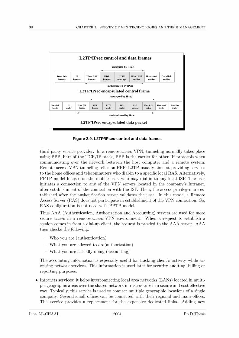
30 CHAPTER 2. SURVEY OF VPN TECHNOLOGIES AND THEIR MANAGEMENT
IPheader
IPsec ESPheader
Data linktrailer
IPsec authtariler
IPheader
Data linkheader
Data linktrailer
IPsec authtrailer
L2TPheader
IPsec ESPheader
UDPheader
PPPheader
PPPpayload
IPsec ESPtrailer
Data linkheader
UDPheader
L2TPmessage
IPsec ESPtrailer
L2TP/IPsec control and data frames
encrypted by IPsec
L2TP/IPsec encapsulated data packet
L2TP/IPsec encapsulated control frame
authenticated by IPsec
authenticated by IPsec
encrypted by IPsec
Figure 2.9. L2TP/IPsec control and data frames
third-party service provider. In a remote-access VPN, tunneling normally takes placeusing PPP. Part of the TCP/IP stack, PPP is the carrier for other IP protocols whencommunicating over the network between the host computer and a remote system.Remote-access VPN tunneling relies on PPP. L2TP usually aims at providing servicesto the home offices and telecommuters who dial-in to a specific local RAS. Alternatively,PPTP model focuses on the mobile user, who may dial-in to any local ISP. The userinitiates a connection to any of the VPN servers located in the company’s Intranet,after establishment of the connection with the ISP. Then, the access privileges are es-tablished after the authentication server validates the user. In this model a RemoteAccess Server (RAS) does not participate in establishment of the VPN connection. So,RAS configuration is not need with PPTP model.
Thus AAA (Authentication, Authorization and Accounting) servers are used for moresecure access in a remote-access VPN environment. When a request to establish asession comes in from a dial-up client, the request is proxied to the AAA server. AAAthen checks the following:
– Who you are (authentication)
– What you are allowed to do (authorization)
– What you are actually doing (accounting)
The accounting information is especially useful for tracking client’s activity while ac-cessing network services. This information is used later for security auditing, billing orreporting purposes.
• Intranets services: it helps interconnecting local area networks (LANs) located in multi-ple geographic areas over the shared network infrastructure in a secure and cost effectiveway. Typically, this service is used to connect multiple geographic locations of a singlecompany. Several small offices can be connected with their regional and main offices.This service provides a replacement for the expensive dedicated links. Adding new
Lina AL-CHAAL 2004 Ph.D Thesis
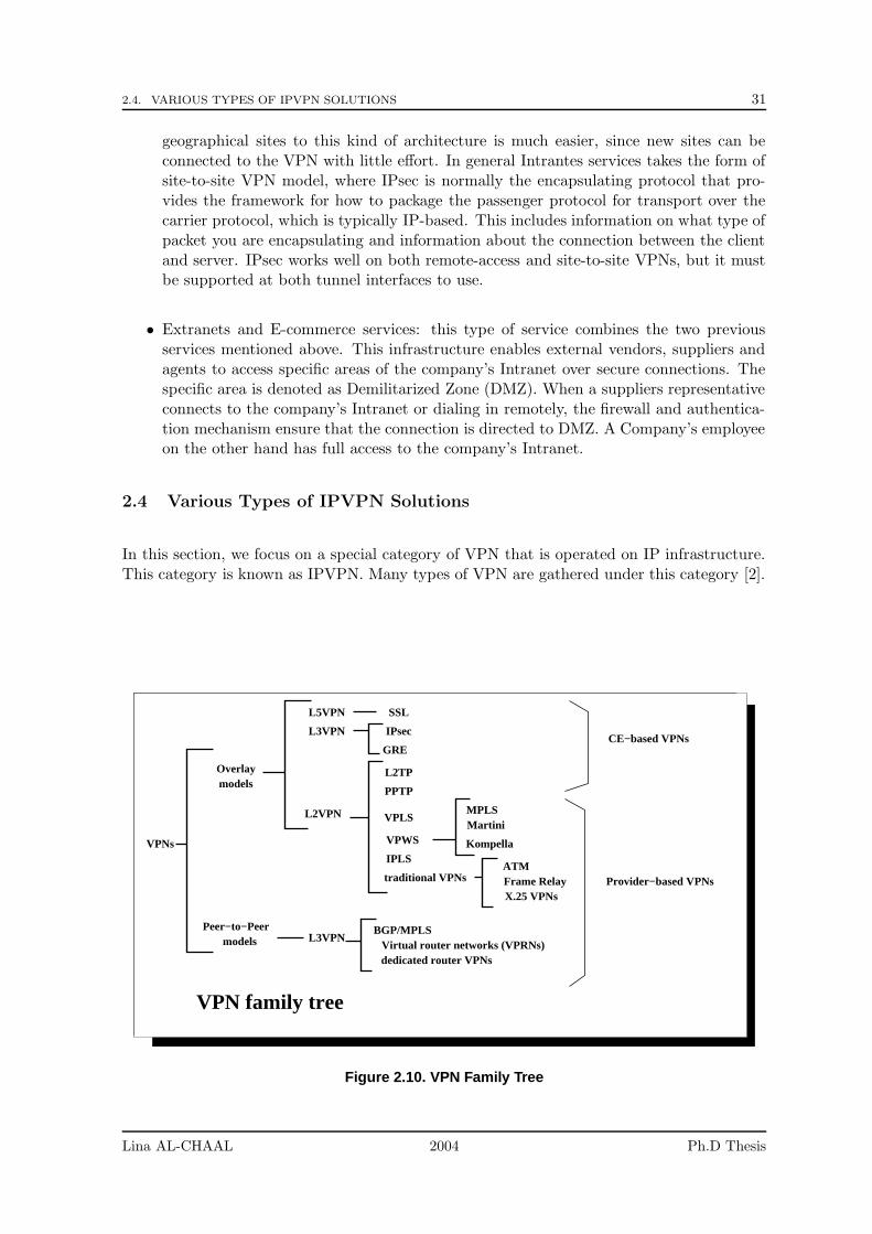
2.4. VARIOUS TYPES OF IPVPN SOLUTIONS 31
geographical sites to this kind of architecture is much easier, since new sites can beconnected to the VPN with little effort. In general Intrantes services takes the form ofsite-to-site VPN model, where IPsec is normally the encapsulating protocol that pro-vides the framework for how to package the passenger protocol for transport over thecarrier protocol, which is typically IP-based. This includes information on what type ofpacket you are encapsulating and information about the connection between the clientand server. IPsec works well on both remote-access and site-to-site VPNs, but it mustbe supported at both tunnel interfaces to use.
• Extranets and E-commerce services: this type of service combines the two previousservices mentioned above. This infrastructure enables external vendors, suppliers andagents to access specific areas of the company’s Intranet over secure connections. Thespecific area is denoted as Demilitarized Zone (DMZ). When a suppliers representativeconnects to the company’s Intranet or dialing in remotely, the firewall and authentica-tion mechanism ensure that the connection is directed to DMZ. A Company’s employeeon the other hand has full access to the company’s Intranet.
2.4 Various Types of IPVPN Solutions
In this section, we focus on a special category of VPN that is operated on IP infrastructure.This category is known as IPVPN. Many types of VPN are gathered under this category [2].
VPNs
dedicated router VPNsVirtual router networks (VPRNs)
BGP/MPLS
ATMFrame RelayX.25 VPNs
VPN family tree
Provider−based VPNs
modelsPeer−to−Peer
L3VPN
models
L2VPN
CE−based VPNs
Overlay
L3VPN IPsec
L5VPN SSL
traditional VPNs
IPLS
VPWS Kompella
MartiniMPLS
VPLS
GRE
PPTP
L2TP
Figure 2.10. VPN Family Tree
Lina AL-CHAAL 2004 Ph.D Thesis
32 CHAPTER 2. SURVEY OF VPN TECHNOLOGIES AND THEIR MANAGEMENT
2.4.1 IPVPN definition
With the overwhelming success of the Internet during last decade, the landscape of telecom-munications has changed radically and the IP protocol has been pervasively deployed incorporate networks. For this reason, business companies made attention of creating secure,private corporate networks using the shared infrastructure of the Internet [27]. Eventuallysharing network resources by using the Internet is definitely more cost effective than usingdedicated facilities. Further, the Internet can be accessed from virtually anywhere in theworld, with operations and administration supplied by the local Internet Service Provider.
IP-based VPNs (IPVPNs) can be defined as a VPN implementation that uses public or sharedIP network resources to emulate the characteristics of an IP-based private network. Theyhave shown potential to become the foundation for a wide range of corporate network services.An increasing number of service providers offer value-added applications and services on theirIPVPN transport networks to generate new revenue and gain competitive advantage.
Different types of ISPs offer different VPN solutions [45], according to the customer needs.Customers of VPN services use shared facilities and equipment, which are managed, engi-neered and operated by a public network operator, either totally or partly.
2.4.2 General Classifications of IPVPN Types
Two general types of IPVPNs exist: Customer Equipment CE-based VPNs, and Provider-based VPNs (AKA Network-based VPNs).
• CE-based VPNs: In a CE-based VPN, knowledge of the customer network is limited tothe Customer Premise Equipment. In this type, VPN access is placed at the customerequipment which provides end-to-end security. Provisioning and management of theVPN is up to the customer network administration, typically by manual configurationof the tunnels between customer equipments, without significant upgrades to the serviceprovider’s network. However, it is common for a service provider to be responsiblefor managing and provisioning the Customer Edge equipment, in order to reduce themanagement requirements of the customer. The tunnels between CE equipments maybe implemented as simple link layer connections such as ATM or Frame Relay, orby means of various encapsulation formats such as GRE, IP-in-IP, IPsec, L2TP, orMulti-Protocol Label Switching (MPLS). Routing in the customer network views thetunnels as simple point-to-point links. Briefly, an CE-based VPN can be defined as anIPVPN that initiates tunneling and encryption at the edge of the customer’s networkfor dedicated locations and on the remote user’s PC for remote access users. Thechallenge with this approach is a problem of scalability when large-scale VPNs shouldbe managed because of their distributed nature. More details in CE-based VPNs insection 2.4.3 and chapter 3.
• Provider-based VPNs: Provider-based VPNs and all related configuration, operationand control are provided by equipments of the service provider’s network. Usuallythese types of VPNs are built on edge devices that are located at the service provider’sPoint of Presence (POP). Customer network is supported by tunnels, which are set upbetween pairs of edge routers. The tunnels may make use of various encapsulations tosend traffic over the Service Provider network. Examples of tunnel encapsulations areGRE, IPsec, IP-in-IP and MPLS. There are two basic types of Provider-based VPNs:Layer 2-based VPN (L2VPN) and Layer 3-based VPN (L3VPN), discussed later. Thechallenge with this approach is that it requires provider’s POPs to be updated to meet
Lina AL-CHAAL 2004 Ph.D Thesis
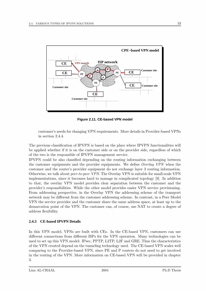
2.4. VARIOUS TYPES OF IPVPN SOLUTIONS 33
���������������������������������������������������������������������������������������������������������������������������������������������������������������������������������������������������������������������������������������������������������������������������������������������������������������������������������������������������������������������������������������������������������������������������������������������������������������������������������������������������������������������������������������������������������������������������������������������������������������������������������������������������������������������������������������������������������������������������������������������������������������������������������������������������������
���������������������������������������������������������������������������������������������������������������������������������������������������������������������������������������������������������������������������������������������������������������������������������������������������������������������������������������������������������������������������������������������������������������������������������������������������������������������������������������������������������������������������������������������������������������������������������������������������������������������������������������������������������������������������������������������������������������������������������������������������������������������������������������������������������
P
PP
P
CE
CE
CE
Customer site Customer site
Customer site
CE
CE ISP network
Customer site
CPE−based VPN model
VPN tunnels
PE
PE
PE
Figure 2.11. CE-based VPN model
customer’s needs for changing VPN requirements. More details in Provider-based VPNsin section 2.4.4.
The previous classification of IPVPN is based on the place where IPVPN functionalities willbe applied whether if it is on the customer side or on the provider side, regardless of whichof the two is the responsible of IPVPN management service.
IPVPN could be also classified depending on the routing information exchanging betweenthe customer equipments and the provider equipments. We define Overlay VPN when thecustomer and the router’s provider equipment do not exchange layer 3 routing information.Otherwise, we talk about peer-to-peer VPN. The Overlay VPN is suitable for small-scale VPNimplementations, since it becomes hard to manage in complicated topology [9]. In additionto that, the overlay VPN model provides clear separation between the customer and theprovider’s responsibilities. While the other model provides easier VPN service provisioning.From addressing perspective, in the Overlay VPN the addressing scheme of the transportnetwork may be different from the customer addressing scheme. In contrast, in a Peer ModelVPN the service provider and the customer share the same address space, at least up to thedemarcation point of the VPN. The customer can, of course, use NAT to create a degree ofaddress flexibility.
2.4.3 CE-based IPVPN Details
In this VPN model, VPNs are built with CEs. In the CE-based VPN, customers can usedifferent connections from different ISPs for the VPN operation. Many technologies can beused to set up this VPN model: IPsec, PPTP, L2TP, L2F and GRE. Thus the characteristicsof the VPN created depend on the tunneling technology used. The CE-based VPN scales wellcomparing to the Provider-based VPN, since PE and P routers do not need to get involvedin the routing of the VPN. More information on CE-based VPN will be provided in chapter3.
Lina AL-CHAAL 2004 Ph.D Thesis
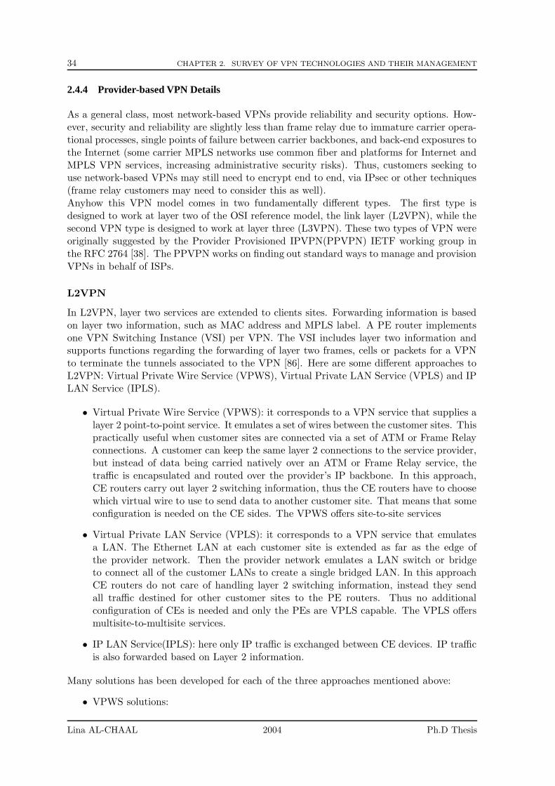
34 CHAPTER 2. SURVEY OF VPN TECHNOLOGIES AND THEIR MANAGEMENT
2.4.4 Provider-based VPN Details
As a general class, most network-based VPNs provide reliability and security options. How-ever, security and reliability are slightly less than frame relay due to immature carrier opera-tional processes, single points of failure between carrier backbones, and back-end exposures tothe Internet (some carrier MPLS networks use common fiber and platforms for Internet andMPLS VPN services, increasing administrative security risks). Thus, customers seeking touse network-based VPNs may still need to encrypt end to end, via IPsec or other techniques(frame relay customers may need to consider this as well).Anyhow this VPN model comes in two fundamentally different types. The first type isdesigned to work at layer two of the OSI reference model, the link layer (L2VPN), while thesecond VPN type is designed to work at layer three (L3VPN). These two types of VPN wereoriginally suggested by the Provider Provisioned IPVPN(PPVPN) IETF working group inthe RFC 2764 [38]. The PPVPN works on finding out standard ways to manage and provisionVPNs in behalf of ISPs.
L2VPN
In L2VPN, layer two services are extended to clients sites. Forwarding information is basedon layer two information, such as MAC address and MPLS label. A PE router implementsone VPN Switching Instance (VSI) per VPN. The VSI includes layer two information andsupports functions regarding the forwarding of layer two frames, cells or packets for a VPNto terminate the tunnels associated to the VPN [86]. Here are some different approaches toL2VPN: Virtual Private Wire Service (VPWS), Virtual Private LAN Service (VPLS) and IPLAN Service (IPLS).
• Virtual Private Wire Service (VPWS): it corresponds to a VPN service that supplies alayer 2 point-to-point service. It emulates a set of wires between the customer sites. Thispractically useful when customer sites are connected via a set of ATM or Frame Relayconnections. A customer can keep the same layer 2 connections to the service provider,but instead of data being carried natively over an ATM or Frame Relay service, thetraffic is encapsulated and routed over the provider’s IP backbone. In this approach,CE routers carry out layer 2 switching information, thus the CE routers have to choosewhich virtual wire to use to send data to another customer site. That means that someconfiguration is needed on the CE sides. The VPWS offers site-to-site services
• Virtual Private LAN Service (VPLS): it corresponds to a VPN service that emulatesa LAN. The Ethernet LAN at each customer site is extended as far as the edge ofthe provider network. Then the provider network emulates a LAN switch or bridgeto connect all of the customer LANs to create a single bridged LAN. In this approachCE routers do not care of handling layer 2 switching information, instead they sendall traffic destined for other customer sites to the PE routers. Thus no additionalconfiguration of CEs is needed and only the PEs are VPLS capable. The VPLS offersmultisite-to-multisite services.
• IP LAN Service(IPLS): here only IP traffic is exchanged between CE devices. IP trafficis also forwarded based on Layer 2 information.
Many solutions has been developed for each of the three approaches mentioned above:
• VPWS solutions:
Lina AL-CHAAL 2004 Ph.D Thesis
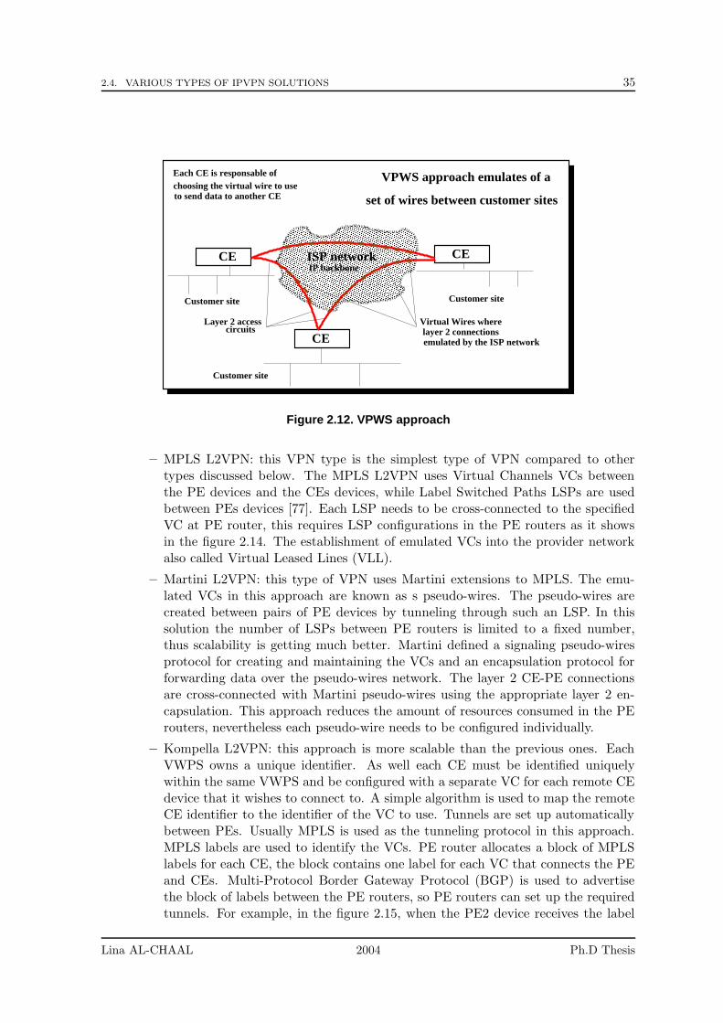
2.4. VARIOUS TYPES OF IPVPN SOLUTIONS 35
���������������������������������������������������������������������������������������������������������������������������������������������������������������������������������������������������������������������������������������������������������������������������������������������������������������������������������������������������������������������������������������������������������������������������������������������������������������������������������������������������������������������������������������������������������������������������������������������������������������������������������������������������������������������������������������������������������������������������������������������������������������������������������������������������������
���������������������������������������������������������������������������������������������������������������������������������������������������������������������������������������������������������������������������������������������������������������������������������������������������������������������������������������������������������������������������������������������������������������������������������������������������������������������������������������������������������������������������������������������������������������������������������������������������������������������������������������������������������������������������������������������������������������������������������������������������������������
VPWS approach emulates of a
set of wires between customer sites
CE
CE CE
Customer site
ISP network
Customer site
IP backbone
Each CE is responsable ofchoosing the virtual wire to useto send data to another CE
circuitsVirtual Wires where
emulated by the ISP networklayer 2 connections
Layer 2 access
Customer site
Figure 2.12. VPWS approach
– MPLS L2VPN: this VPN type is the simplest type of VPN compared to othertypes discussed below. The MPLS L2VPN uses Virtual Channels VCs betweenthe PE devices and the CEs devices, while Label Switched Paths LSPs are usedbetween PEs devices [77]. Each LSP needs to be cross-connected to the specifiedVC at PE router, this requires LSP configurations in the PE routers as it showsin the figure 2.14. The establishment of emulated VCs into the provider networkalso called Virtual Leased Lines (VLL).
– Martini L2VPN: this type of VPN uses Martini extensions to MPLS. The emu-lated VCs in this approach are known as s pseudo-wires. The pseudo-wires arecreated between pairs of PE devices by tunneling through such an LSP. In thissolution the number of LSPs between PE routers is limited to a fixed number,thus scalability is getting much better. Martini defined a signaling pseudo-wiresprotocol for creating and maintaining the VCs and an encapsulation protocol forforwarding data over the pseudo-wires network. The layer 2 CE-PE connectionsare cross-connected with Martini pseudo-wires using the appropriate layer 2 en-capsulation. This approach reduces the amount of resources consumed in the PErouters, nevertheless each pseudo-wire needs to be configured individually.
– Kompella L2VPN: this approach is more scalable than the previous ones. EachVWPS owns a unique identifier. As well each CE must be identified uniquelywithin the same VWPS and be configured with a separate VC for each remote CEdevice that it wishes to connect to. A simple algorithm is used to map the remoteCE identifier to the identifier of the VC to use. Tunnels are set up automaticallybetween PEs. Usually MPLS is used as the tunneling protocol in this approach.MPLS labels are used to identify the VCs. PE router allocates a block of MPLSlabels for each CE, the block contains one label for each VC that connects the PEand CEs. Multi-Protocol Border Gateway Protocol (BGP) is used to advertisethe block of labels between the PE routers, so PE routers can set up the requiredtunnels. For example, in the figure 2.15, when the PE2 device receives the label
Lina AL-CHAAL 2004 Ph.D Thesis
36 CHAPTER 2. SURVEY OF VPN TECHNOLOGIES AND THEIR MANAGEMENT
���������������������������������������������������������������������������������������������������������������������������������������������������������������������������������������������������������������������������������������������������������������������������������������������������������������������������������������������������������������������������������������������������������������������������������������������������������������������������������������������������������������������������������������������������������������������������������������������������������������������������������������������������������������������������������������������������������������������������������������������������������������������������������������������������������
���������������������������������������������������������������������������������������������������������������������������������������������������������������������������������������������������������������������������������������������������������������������������������������������������������������������������������������������������������������������������������������������������������������������������������������������������������������������������������������������������������������������������������������������������������������������������������������������������������������������������������������������������������������������������������������������������������������������������������������������������������������������������������������������������������
CE
VPLS approach emulates of a
LAN bridge/switch between customer sites
CE
Customer site
CE
Customer site
Customer site
ISP network
Layer 2 connections
CEs are simply send traffic to the PE routers
Figure 2.13. VPLS approach
block from PE1, it knows that the labels are allocated for sending data to CE1.There is one label for each remote CE to send data to the CE1. PE2 ignores alllabels destined to other CE devices and takes care only of the label L12, whereit signifies the label allocated to VC2 for CE1. Now CE2 is able to send data toCE1. To do so, CE2 sends data over VC1 to PE2. As soon as PE2 gets the data,it knows that they should be tunneled to PE1 with the label L12 since they werereceived over VC1. When PE1 receives the data with the label L12, the label isremoved and the data is sent over VC2 to CE1.
• VPLS solutions: the VPLS is based on a full mesh of Martini pseudo-wires set up be-tween the PE routers that are participating to a specific VPLS. Like Ethernet switches,PE devices learn MAC addresses of carried packets to successfully forward data fromone CE to another. In this type of VPN, when a PE router participates to a VPLS,it uses BGP as auto-discovery mechanism to learn about VPLS membership, and setsup Martini pseudo-mires with other PEs of the same VPLS. This type of VPN doesplace a significant burden on the PE devices, since those later should be learn aboutall MAC addresses of the attached VPLSs, should be able to forward VPLS instancesand should be also responsible of tunnel management and VPLS configuration.
• IPLS solutions: by snooping IP and ARP frames, each PE device learns automaticallyabout the local CE devices. Using also the BGP auto-discovery mechanism, the PEdevice learns about remote PE devices in the same IPLS. For each locally CE device,a PE sets up Martini pseudo-wire to each remote PE device in the same IPLS. Whenthe PE device receives data on this pseudo-wire, it forwards data straightly to theCE device without even looking at the IP address. Otherwise, when a pseudo-wire issignaled to a remote PE device, the IP address and the MAC address of the remote CEis included, thus each PE device could build up a table of all IP addresses and MACaddresses of all remote CE devices.
Lina AL-CHAAL 2004 Ph.D Thesis
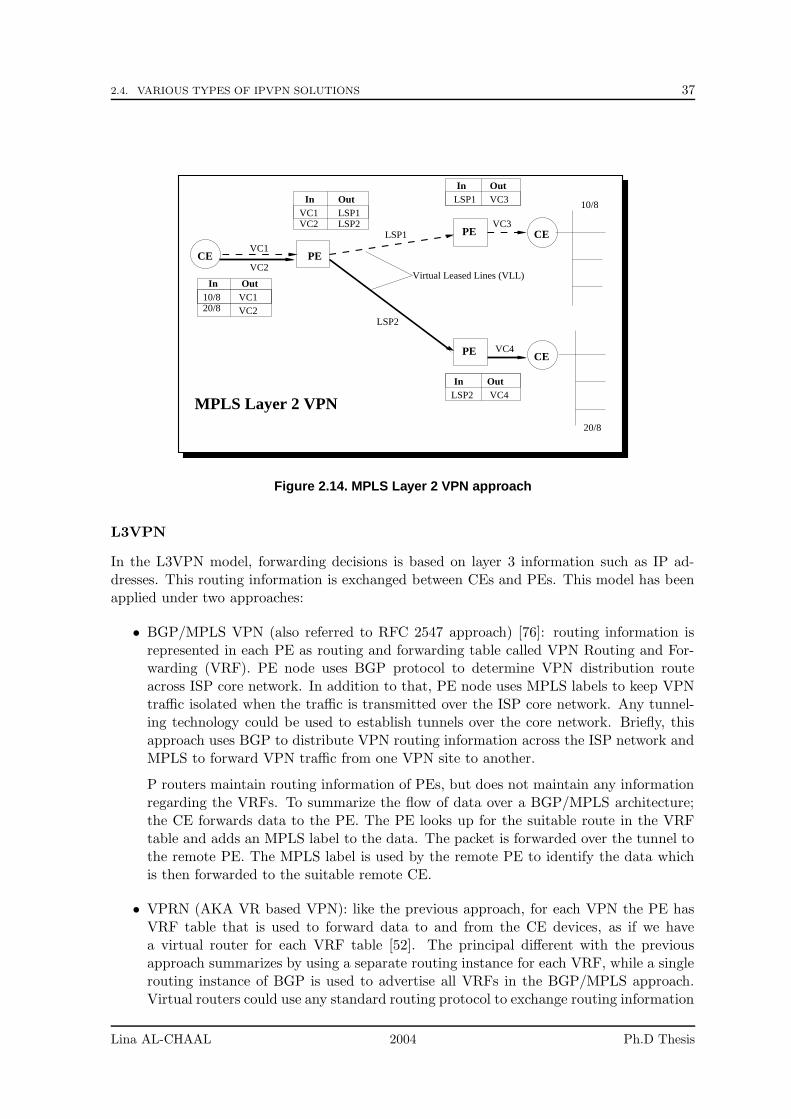
2.4. VARIOUS TYPES OF IPVPN SOLUTIONS 37
CE
CE
CE
PE
OutIn10/820/8
VC1VC2
PE
20/8
PE
10/8In OutVC1VC2
LSP1LSP2
VC1
VC2
In Out
LSP1
LSP1
LSP2
In OutLSP2
VC3
VC3
VC4
VC4
MPLS Layer 2 VPN
Virtual Leased Lines (VLL)
Figure 2.14. MPLS Layer 2 VPN approach
L3VPN
In the L3VPN model, forwarding decisions is based on layer 3 information such as IP ad-dresses. This routing information is exchanged between CEs and PEs. This model has beenapplied under two approaches:
• BGP/MPLS VPN (also referred to RFC 2547 approach) [76]: routing information isrepresented in each PE as routing and forwarding table called VPN Routing and For-warding (VRF). PE node uses BGP protocol to determine VPN distribution routeacross ISP core network. In addition to that, PE node uses MPLS labels to keep VPNtraffic isolated when the traffic is transmitted over the ISP core network. Any tunnel-ing technology could be used to establish tunnels over the core network. Briefly, thisapproach uses BGP to distribute VPN routing information across the ISP network andMPLS to forward VPN traffic from one VPN site to another.
P routers maintain routing information of PEs, but does not maintain any informationregarding the VRFs. To summarize the flow of data over a BGP/MPLS architecture;the CE forwards data to the PE. The PE looks up for the suitable route in the VRFtable and adds an MPLS label to the data. The packet is forwarded over the tunnel tothe remote PE. The MPLS label is used by the remote PE to identify the data whichis then forwarded to the suitable remote CE.
• VPRN (AKA VR based VPN): like the previous approach, for each VPN the PE hasVRF table that is used to forward data to and from the CE devices, as if we havea virtual router for each VRF table [52]. The principal different with the previousapproach summarizes by using a separate routing instance for each VRF, while a singlerouting instance of BGP is used to advertise all VRFs in the BGP/MPLS approach.Virtual routers could use any standard routing protocol to exchange routing information
Lina AL-CHAAL 2004 Ph.D Thesis
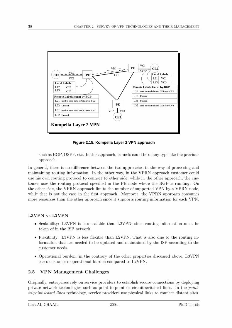
38 CHAPTER 2. SURVEY OF VPN TECHNOLOGIES AND THEIR MANAGEMENT
L23
L31
L32
L21
Unused
used to send data to CE3 over CV3
Unused
used to send data to CE2 over CV2
Remote Labels learnt by BGP
CE3
PE
PE
VC2
VC3
VC1L12
Local LabelsL12 VC2L13 VC3
Kompella Layer 2 VPN
Local LabelsL21 VC1
VC3L23
VC3CE1
CE2
L21
VC2 VC1
PEL31
L32
Remote Labels learnt by BGPL12
L13
Unused
Unused
used to send data to CE1 over CV1
used to send data to CE3 over CV3
Figure 2.15. Kompella Layer 2 VPN approach
such as BGP, OSPF, etc. In this approach, tunnels could be of any type like the previousapproach.
In general, there is no difference between the two approaches in the way of processing andmaintaining routing information. In the other way, in the VPRN approach customer coulduse his own routing protocol to connect to other side, while in the other approach, the cus-tomer uses the routing protocol specified in the PE node where the BGP is running. Onthe other side, the VPRN approach limits the number of supported VPN by a VPRN node,while that is not the case in the first approach. Moreover, the VPRN approach consumesmore resources than the other approach since it supports routing information for each VPN.
L3VPN vs L2VPN
• Scalability: L3VPN is less scalable than L2VPN, since routing information must betaken of in the ISP network.
• Flexibility: L3VPN is less flexible than L2VPN. That is also due to the routing in-formation that are needed to be updated and maintained by the ISP according to thecustomer needs.
• Operational burden: in the contrary of the other properties discussed above, L3VPNeases customer’s operational burden compared to L2VPN.
2.5 VPN Management Challenges
Originally, enterprises rely on service providers to establish secure connections by deployingprivate network technologies such as point-to-point or circuit-switched lines. In the point-to-point leased lines technology, service providers use physical links to connect distant sites.
Lina AL-CHAAL 2004 Ph.D Thesis
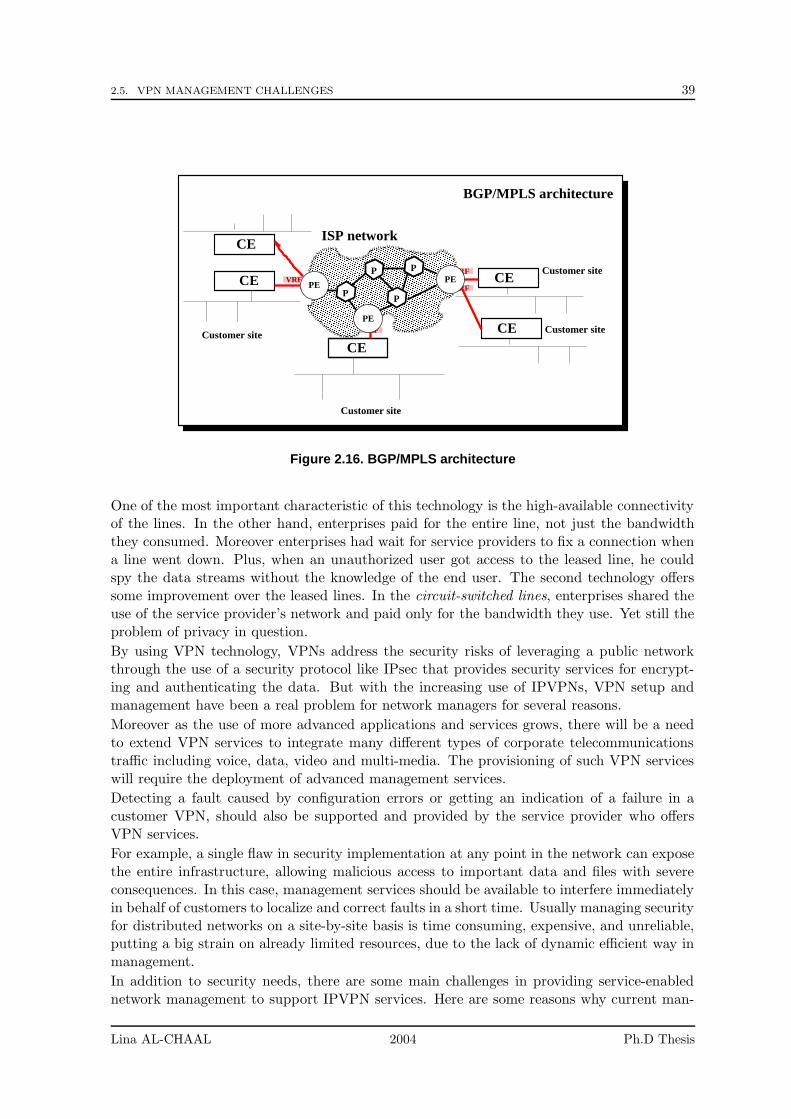
2.5. VPN MANAGEMENT CHALLENGES 39
���������������������������������������������������������������������������������������������������������������������������������������������������������������������������������������������������������������������������������������������������������������������������������������������������������������������������������������������������������������������������������������������������������������������������������������������������������������������������������������������������������������������������������������������������������������������������������������������������������������������������������������������������������������������������������������������������������������������������������������������������������������������������������������������������������
���������������������������������������������������������������������������������������������������������������������������������������������������������������������������������������������������������������������������������������������������������������������������������������������������������������������������������������������������������������������������������������������������������������������������������������������������������������������������������������������������������������������������������������������������������������������������������������������������������������������������������������������������������������������������������������������������������������������������������������������������������������������������������������������������������
CE
P
PP
P
CEVRF
VRF
VRF
VRFCE
Customer site
Customer site
Customer site
Customer site
CE
BGP/MPLS architecture
CEISP network
PE
PE
PE
Figure 2.16. BGP/MPLS architecture
One of the most important characteristic of this technology is the high-available connectivityof the lines. In the other hand, enterprises paid for the entire line, not just the bandwidththey consumed. Moreover enterprises had wait for service providers to fix a connection whena line went down. Plus, when an unauthorized user got access to the leased line, he couldspy the data streams without the knowledge of the end user. The second technology offerssome improvement over the leased lines. In the circuit-switched lines, enterprises shared theuse of the service provider’s network and paid only for the bandwidth they use. Yet still theproblem of privacy in question.
By using VPN technology, VPNs address the security risks of leveraging a public networkthrough the use of a security protocol like IPsec that provides security services for encrypt-ing and authenticating the data. But with the increasing use of IPVPNs, VPN setup andmanagement have been a real problem for network managers for several reasons.
Moreover as the use of more advanced applications and services grows, there will be a needto extend VPN services to integrate many different types of corporate telecommunicationstraffic including voice, data, video and multi-media. The provisioning of such VPN serviceswill require the deployment of advanced management services.
Detecting a fault caused by configuration errors or getting an indication of a failure in acustomer VPN, should also be supported and provided by the service provider who offersVPN services.
For example, a single flaw in security implementation at any point in the network can exposethe entire infrastructure, allowing malicious access to important data and files with severeconsequences. In this case, management services should be available to interfere immediatelyin behalf of customers to localize and correct faults in a short time. Usually managing securityfor distributed networks on a site-by-site basis is time consuming, expensive, and unreliable,putting a big strain on already limited resources, due to the lack of dynamic efficient way inmanagement.
In addition to security needs, there are some main challenges in providing service-enablednetwork management to support IPVPN services. Here are some reasons why current man-
Lina AL-CHAAL 2004 Ph.D Thesis
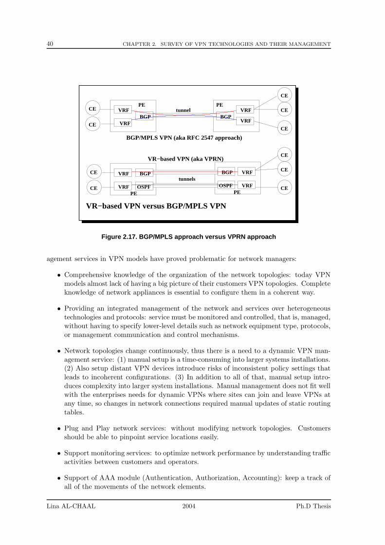
40 CHAPTER 2. SURVEY OF VPN TECHNOLOGIES AND THEIR MANAGEMENT
OSPF OSPF
BGP BGP
BGP BGP
CE
CE
CE
CE
CE
CE
CE
CE
CE
CE
VRF
VRF
VRF
VRF
VRF
VRF
VRF
VRFPE PE
PEPE
VR−based VPN versus BGP/MPLS VPN
tunnels
tunnel
BGP/MPLS VPN (aka RFC 2547 approach)
VR−based VPN (aka VPRN)
Figure 2.17. BGP/MPLS approach versus VPRN approach
agement services in VPN models have proved problematic for network managers:
• Comprehensive knowledge of the organization of the network topologies: today VPNmodels almost lack of having a big picture of their customers VPN topologies. Completeknowledge of network appliances is essential to configure them in a coherent way.
• Providing an integrated management of the network and services over heterogeneoustechnologies and protocols: service must be monitored and controlled, that is, managed,without having to specify lower-level details such as network equipment type, protocols,or management communication and control mechanisms.
• Network topologies change continuously, thus there is a need to a dynamic VPN man-agement service: (1) manual setup is a time-consuming into larger systems installations.(2) Also setup distant VPN devices introduce risks of inconsistent policy settings thatleads to incoherent configurations. (3) In addition to all of that, manual setup intro-duces complexity into larger system installations. Manual management does not fit wellwith the enterprises needs for dynamic VPNs where sites can join and leave VPNs atany time, so changes in network connections required manual updates of static routingtables.
• Plug and Play network services: without modifying network topologies. Customersshould be able to pinpoint service locations easily.
• Support monitoring services: to optimize network performance by understanding trafficactivities between customers and operators.
• Support of AAA module (Authentication, Authorization, Accounting): keep a track ofall of the movements of the network elements.
Lina AL-CHAAL 2004 Ph.D Thesis
2.6. PARTIAL CONCLUSIONS 41
• Secure negotiation between customers and operators: security issue is a critical andimportant point into any management service.
• Coherent deployment of security policies: these policies should contain informationrelated to security issues and firewall rules.
Currently, proprietary and individual methods are often used to offer VPN manage services.
2.6 Partial Conclusions
IPVPN evolutions has been led by several working groups and big organizations like theIETF and the ITU. Yet, there are several fields, which have not been addressed so far, orpartially discussed. Management solutions and requirements are still need to be developedand implemented to cover customer business needs and outsource customer managementhassles. So far, we have given an overview of the current VPN models, describing their char-acteristics and applications. Then we analyzed current VPN models regarding managementrequirements and their actual challenges. In the following chapter, we presents a VPN modeloffering management services in a flexible and dynamic way.
Lina AL-CHAAL 2004 Ph.D Thesis

42 CHAPTER 2. SURVEY OF VPN TECHNOLOGIES AND THEIR MANAGEMENT
Lina AL-CHAAL 2004 Ph.D Thesis
Chapter 3
Our Dynamic CE-based VPNApproach
Contents
3.1 Introduction . . . . . . . . . . . . . . . . . . . . . . . . . . . . . . . 43
3.2 Architecture . . . . . . . . . . . . . . . . . . . . . . . . . . . . . . . 44
3.2.1 Classification of our Approach . . . . . . . . . . . . . . . . . . . . . 44
3.2.2 General Description . . . . . . . . . . . . . . . . . . . . . . . . . . . 45
3.2.3 Technical Details . . . . . . . . . . . . . . . . . . . . . . . . . . . . . 48
3.3 Dynamic Management versus Manual Management . . . . . . . . 50
3.4 Implementation Details . . . . . . . . . . . . . . . . . . . . . . . . . 52
3.4.1 The SMS Architecture . . . . . . . . . . . . . . . . . . . . . . . . . . 52
3.4.2 The SES Architecture . . . . . . . . . . . . . . . . . . . . . . . . . . 52
3.5 Features of our Approach: a Summary . . . . . . . . . . . . . . . 54
In this chapter, we introduce our dynamic CE-based VPN approach, its characteristics aswell as its dynamic management features.
3.1 Introduction
In a well-managed VPN approach, the following features should be covered: provisioning,monitoring, accounting, security and maintenance.For the rest of this document, we are going to use the term ”VPN site” to refer either toa ”Road Warrior” connected to the office from home or from a hotel, or a fixed personalcomputer at home, or a remote complex network like shows in figure 11.1. Each VPN sitehas at least one CE device. We refer to the owner of a VPN site as a ”VPN client” or a”VPN customer”.In this chapter, we presents our dynamic CE-based VPN approach. We will see how thisapproach nicely covers the previous features, while keeping a simple architecture.The remainder of this chapter is organized as follows: section 3.2 presents our VPN approachin details, giving an overview of its components and its characteristics; the section 3.3 focuseson the benefits we get by applying our approach and how the dynamism in this approach playsa significant role from the management’s viewpoint. Finally, we provide some implementationdetails in section 3.4 and summarize in section 3.5.
43
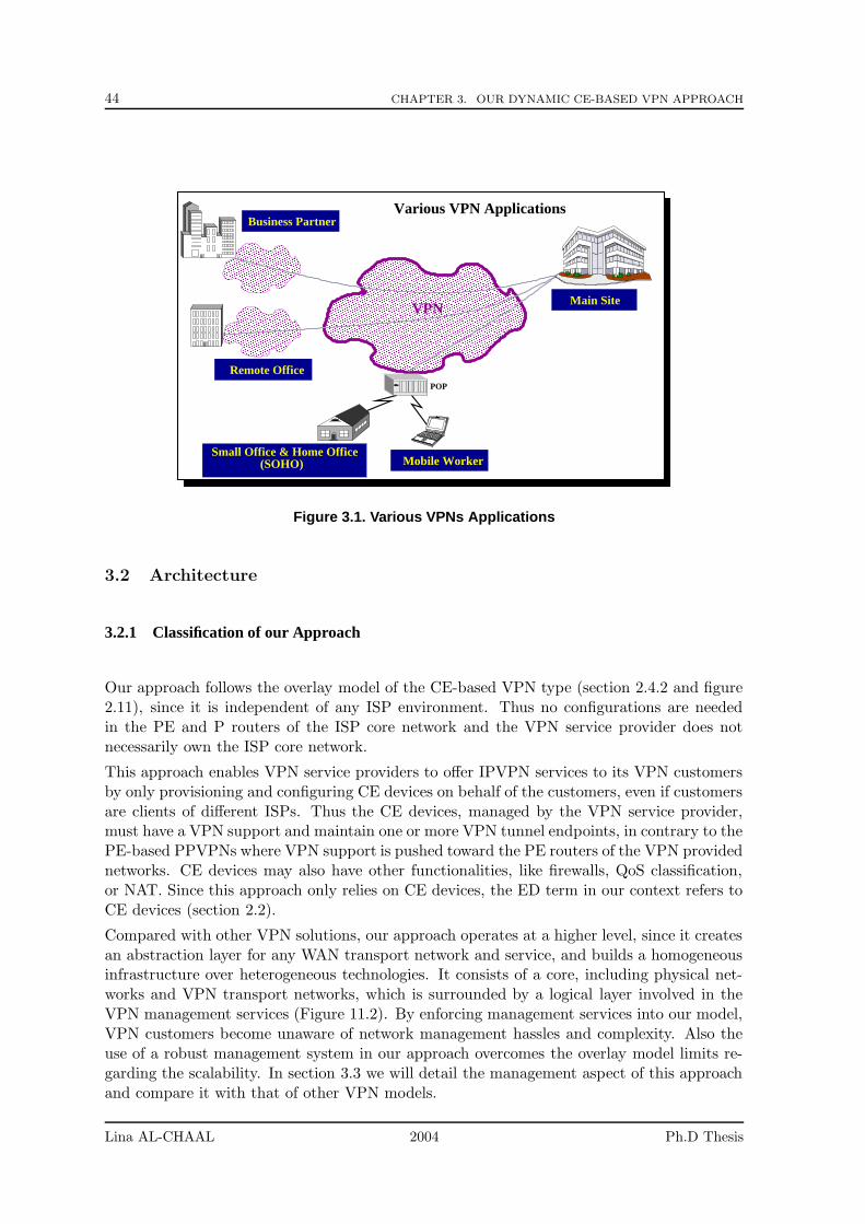
44 CHAPTER 3. OUR DYNAMIC CE-BASED VPN APPROACH
������������������������������������������������������������������������������������������������������������������������������������������������������������������������������������������������������������������������������������������������������������������������������������������������������������������������������������������������������������������������������������������������������������������������������������������������������������������������������������������������������������������������������������������������������������������������������������������������������������������������������������������������������������������������������������������������������������������������������������������������������������������������������������������������������������������������������������������������������������������������������������������������������������������������������������������������������������������������������������������������������������������������
������������������������������������������������������������������������������������������������������������������������������������������������������������������������������������������������������������������������������������������������������������������������������������������������������������������������������������������������������������������������������������������������������������������������������������������������������������������������������������������������������������������������������������������������������������������������������������������������������������������������������������������������������������������������������������������������������������������������������������������������������������������������������������������������������������������������������������������������������������������������������������������������������������������������������������������������������������������������������������������������������������������������
���������������������������������������������������������������������������������������������������������������������������������������������������������������������
���������������������������������������������������������������������������������������������������������������������������������������������������������������������
���������������������������������������������������������������������������������������������������������������������������������������������������������������������
��������������������������������������������������������������������������������������������������������������������������������������������������������������������� Main Site
Business Partner
Remote OfficePOP
Mobile Worker
VPN
Small Office & Home Office(SOHO)
Various VPN Applications
Figure 3.1. Various VPNs Applications
3.2 Architecture
3.2.1 Classification of our Approach
Our approach follows the overlay model of the CE-based VPN type (section 2.4.2 and figure2.11), since it is independent of any ISP environment. Thus no configurations are neededin the PE and P routers of the ISP core network and the VPN service provider does notnecessarily own the ISP core network.
This approach enables VPN service providers to offer IPVPN services to its VPN customersby only provisioning and configuring CE devices on behalf of the customers, even if customersare clients of different ISPs. Thus the CE devices, managed by the VPN service provider,must have a VPN support and maintain one or more VPN tunnel endpoints, in contrary to thePE-based PPVPNs where VPN support is pushed toward the PE routers of the VPN providednetworks. CE devices may also have other functionalities, like firewalls, QoS classification,or NAT. Since this approach only relies on CE devices, the ED term in our context refers toCE devices (section 2.2).
Compared with other VPN solutions, our approach operates at a higher level, since it createsan abstraction layer for any WAN transport network and service, and builds a homogeneousinfrastructure over heterogeneous technologies. It consists of a core, including physical net-works and VPN transport networks, which is surrounded by a logical layer involved in theVPN management services (Figure 11.2). By enforcing management services into our model,VPN customers become unaware of network management hassles and complexity. Also theuse of a robust management system in our approach overcomes the overlay model limits re-garding the scalability. In section 3.3 we will detail the management aspect of this approachand compare it with that of other VPN models.
Lina AL-CHAAL 2004 Ph.D Thesis
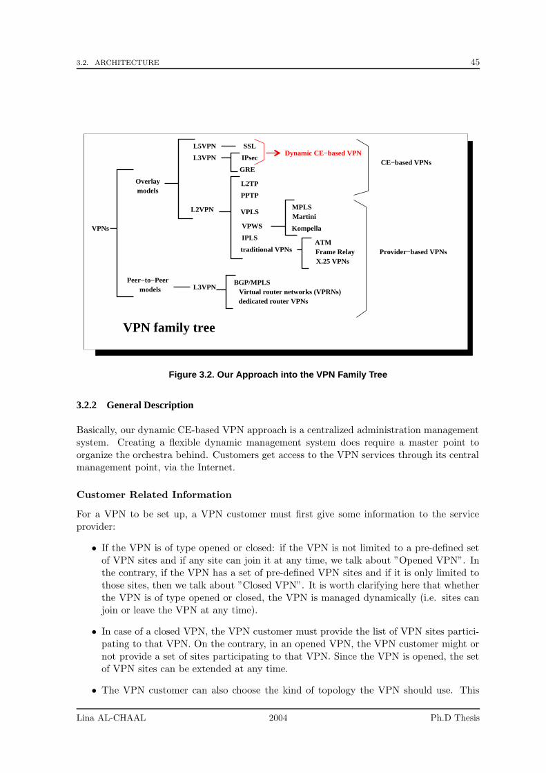
3.2. ARCHITECTURE 45
VPNs
dedicated router VPNsVirtual router networks (VPRNs)
BGP/MPLS
ATMFrame RelayX.25 VPNs
VPN family tree
Provider−based VPNs
modelsPeer−to−Peer
L3VPN
models
L2VPN
CE−based VPNs
Overlay
L3VPN IPsec
L5VPN SSL
traditional VPNs
IPLS
VPWS Kompella
MartiniMPLS
VPLS
Dynamic CE−based VPN
GRE
PPTP
L2TP
Figure 3.2. Our Approach into the VPN Family Tree
3.2.2 General Description
Basically, our dynamic CE-based VPN approach is a centralized administration managementsystem. Creating a flexible dynamic management system does require a master point toorganize the orchestra behind. Customers get access to the VPN services through its centralmanagement point, via the Internet.
Customer Related Information
For a VPN to be set up, a VPN customer must first give some information to the serviceprovider:
• If the VPN is of type opened or closed: if the VPN is not limited to a pre-defined setof VPN sites and if any site can join it at any time, we talk about ”Opened VPN”. Inthe contrary, if the VPN has a set of pre-defined VPN sites and if it is only limited tothose sites, then we talk about ”Closed VPN”. It is worth clarifying here that whetherthe VPN is of type opened or closed, the VPN is managed dynamically (i.e. sites canjoin or leave the VPN at any time).
• In case of a closed VPN, the VPN customer must provide the list of VPN sites partici-pating to that VPN. On the contrary, in an opened VPN, the VPN customer might ornot provide a set of sites participating to that VPN. Since the VPN is opened, the setof VPN sites can be extended at any time.
• The VPN customer can also choose the kind of topology the VPN should use. This
Lina AL-CHAAL 2004 Ph.D Thesis
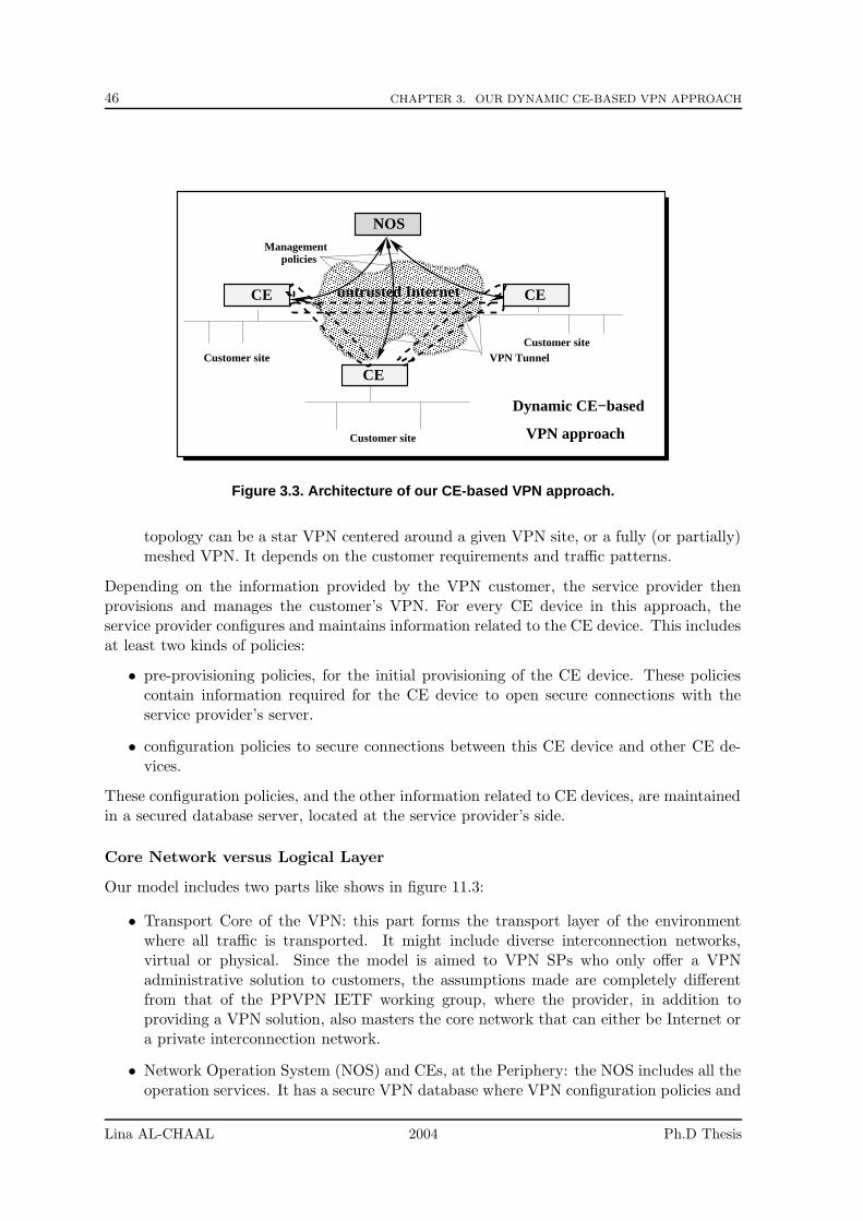
46 CHAPTER 3. OUR DYNAMIC CE-BASED VPN APPROACH
���������������������������������������������������������������������������������������������������������������������������������������������������������������������������������������������������������������������������������������������������������������������������������������������������������������������������������������������������������������������������������������������������������������������������������������������������������������������������������������������������������������������������������������������������������������������������������������������������������������������������������������������������������������������������������������������������������������������������������������������������������������������������������������������������������
���������������������������������������������������������������������������������������������������������������������������������������������������������������������������������������������������������������������������������������������������������������������������������������������������������������������������������������������������������������������������������������������������������������������������������������������������������������������������������������������������������������������������������������������������������������������������������������������������������������������������������������������������������������������������������������������������������������������������������������������������������������
Dynamic CE−based
VPN approach
policies
CE
Customer site
Customer site
Customer siteVPN Tunnel
NOS
CE
CE
Management
untrusted Internet
Figure 3.3. Architecture of our CE-based VPN approach.
topology can be a star VPN centered around a given VPN site, or a fully (or partially)meshed VPN. It depends on the customer requirements and traffic patterns.
Depending on the information provided by the VPN customer, the service provider thenprovisions and manages the customer’s VPN. For every CE device in this approach, theservice provider configures and maintains information related to the CE device. This includesat least two kinds of policies:
• pre-provisioning policies, for the initial provisioning of the CE device. These policiescontain information required for the CE device to open secure connections with theservice provider’s server.
• configuration policies to secure connections between this CE device and other CE de-vices.
These configuration policies, and the other information related to CE devices, are maintainedin a secured database server, located at the service provider’s side.
Core Network versus Logical Layer
Our model includes two parts like shows in figure 11.3:
• Transport Core of the VPN: this part forms the transport layer of the environmentwhere all traffic is transported. It might include diverse interconnection networks,virtual or physical. Since the model is aimed to VPN SPs who only offer a VPNadministrative solution to customers, the assumptions made are completely differentfrom that of the PPVPN IETF working group, where the provider, in addition toproviding a VPN solution, also masters the core network that can either be Internet ora private interconnection network.
• Network Operation System (NOS) and CEs, at the Periphery: the NOS includes all theoperation services. It has a secure VPN database where VPN configuration policies and
Lina AL-CHAAL 2004 Ph.D Thesis
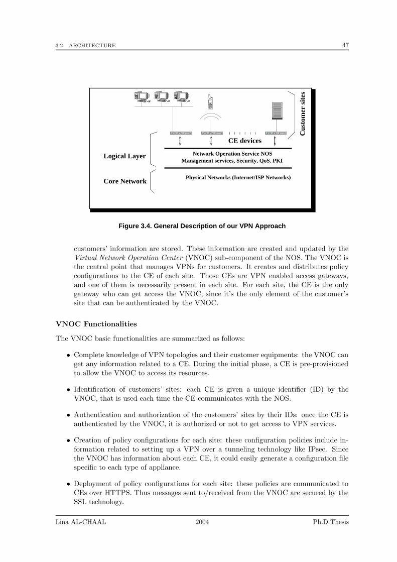
3.2. ARCHITECTURE 47
Core Network
Network Operation Service NOSManagement services, Security, QoS, PKI
Logical Layer
Cus
tom
er s
ites
Physical Networks (Internet/ISP Networks)
CE devices
��������
��������
������������
Figure 3.4. General Description of our VPN Approach
customers’ information are stored. These information are created and updated by theVirtual Network Operation Center (VNOC) sub-component of the NOS. The VNOC isthe central point that manages VPNs for customers. It creates and distributes policyconfigurations to the CE of each site. Those CEs are VPN enabled access gateways,and one of them is necessarily present in each site. For each site, the CE is the onlygateway who can get access the VNOC, since it’s the only element of the customer’ssite that can be authenticated by the VNOC.
VNOC Functionalities
The VNOC basic functionalities are summarized as follows:
• Complete knowledge of VPN topologies and their customer equipments: the VNOC canget any information related to a CE. During the initial phase, a CE is pre-provisionedto allow the VNOC to access its resources.
• Identification of customers’ sites: each CE is given a unique identifier (ID) by theVNOC, that is used each time the CE communicates with the NOS.
• Authentication and authorization of the customers’ sites by their IDs: once the CE isauthenticated by the VNOC, it is authorized or not to get access to VPN services.
• Creation of policy configurations for each site: these configuration policies include in-formation related to setting up a VPN over a tunneling technology like IPsec. Sincethe VNOC has information about each CE, it could easily generate a configuration filespecific to each type of appliance.
• Deployment of policy configurations for each site: these policies are communicated toCEs over HTTPS. Thus messages sent to/received from the VNOC are secured by theSSL technology.
Lina AL-CHAAL 2004 Ph.D Thesis
48 CHAPTER 3. OUR DYNAMIC CE-BASED VPN APPROACH
• Monitoring of VPNs and CEs: the VNOC keeps track of each VPN status and CEactivities.
CE/VNOC Messages
The CE/VNOC dialog is based on XML messages sent over HTTPS. A special API has beendefined and developed to handle several requests between a CE device and the VNOC. EachCE can issue requests to the VNOC to join, leave or query a VPN. For instance, in case ofa “join request”, if the site is authorized, the VNOC sends back the VPN configuration tothe CE of the site and updates the configuration policies of the other CEs concerned by thisVPN and interested in establishing VPN tunnels with that device.
At the beginning, the API was limited only to three basic functions for managing VPNs:
• JoinVPN message: the CE device sends this message to the VNOC when the CE devicewants to join a VPN whose identification is specified.
• LeaveVPN message: the CE device sends this message along with VPN’s identificationto the VNOC when the CE device wants to leave the VPN.
• QueryVPN message: the CE device sends this message along with the VPN’s identifi-cation to the VNOC who returns information about all CE devices belonging to thisVPN.
Security Protocols
IPsec is the security protocol chosen in our VPN approach to secure site-to-site communi-cations (i.e. communications among CE devices), while sites-to-VNOC and VNOC-to-sitescommunications are secured by SSL connections.
A PKI system can also be a fundamental component of the NOS. With a PKI, the NOScan issue X.509-compliant digital certificates, create key pairs and manage these keys andcertificates in behalf of the VPN customers.
Later, in chapter 6, we will define another component, the Management Operation Point(MOP), to refer to the combination of the VNOC and a UDDI repository.
3.2.3 Technical Details
Initial Phase: Initialization of CE Devices
Each CE device must be pre-provisioned with some key information related to the NOS (likethe VNOC address or the CA server address if it exists). This information then enables theCE device to contact the NOS, be identified, and obtain further configuration policies.
In our context, pre-provisioning is done by using a simple web console. A VPN customeruses this console to begin the initialization of its CE device. Thanks to this minimal infor-mation, the CE device then asks the NOS to further configure it, and the NOS pushes allthe required configuration policies to the CE device. In particular the CE device is given aunique identifier, generated dynamically by the NOS, that will be used in all communicationsbetween the CE and the NOS.
Once this phase is over, the CE device is now able to contact the NOS and ask for VPNservices.
Lina AL-CHAAL 2004 Ph.D Thesis
3.2. ARCHITECTURE 49
Configuration of CE devices
A CE device that wants to join a specific VPN sends a JoinVPN message to the VNOC. TheVNOC verifies the legibility of the CE device to participate to that VPN and triggers thesuitable action, either by refusing the CE device request or by sending back the configurationpolicies required to secure connections with other CE devices in that VPN. These configu-ration policies depend on the information obtained by the VNOC from the VPN customer(e.g. the VPN star versus mesh topology, the opened/closed VPN type, and if it is closedthe identifications of CE devices that belong to it). The configuration policies are updatedby the VNOC each time there is a new modification related to the CE status or the VPNsto which it takes part.
Once a CE device has obtained the configuration policies for a specific VPN, it can handle thetraffic destined to the other CE devices of that VPN. So this traffic can be either discardedor processed according to a suitable SA, as discussed in the following section.
Negotiation of IPsec Parameters
The configuration policies obtained previously contain security policies. These security poli-cies indicate in particular if the traffic destined to a peer CE device must be encrypted byIPsec or not. If yes, then the IPsec parameters must be negotiated thanks to IKE (sec-tion 2.3.3).
In fact, each time the IPsec module of the CE device receives some traffic to forward, itchecks if any secure channel is already established to the destination. If not the IPsec clientstarts negotiating an IKE phase 1 exchange. As already explained, the main purpose of IKEphase 1 is to authenticate the IPsec peers and to set up a secure channel between the peers,in order to enable IKE phase 2 exchanges later on.
In our approach, the authentication between two CE devices during the IKE negotiation relieson the use of digital signatures (let us remind that the NOS has sent the necessary informationto CE devices during the initial phase). This information contains digital certificates of theCE devices that include the CEs’public keys (issued by a local CA server located at the NOSor by a third party CA server such as VeriSgin), and a digital signature from the CA.
The CA may generate a public key and a private key (a key pair) or the VPN customerapplying for a certificate may have to generate their own key pair and send a signed requestcontaining their public key to the CA for validation. The VPN customer applying for acertificate may prefer to generate their own key pair so as to ensure that the private keynever leaves their control and as a result is less likely to be available to anyone else.
IKE phase 2 can now start. Its main goal is to negotiate IPsec SAs and generate the requiredkey material for IPsec.
Exchanging Data Between Two CE Devices
After establishing IPsec SAs, an IPsec tunnel can be activated between both CE devicesand traffic exchanged. As explained in section 2.3.3, two modes exist for IPsec: transportmode and tunnel mode. In our case, IPsec is used in tunnel mode. So the CE device mustfirst analyze the private IP packets arriving from its attached local site and select/setup anappropriate SA with the appropriate destination CE device. IPsec then authenticates andencrypts the private IP packets according to the rules described in the SA, encapsulates thepacket in an IPsec header and re-encapsulates the whole in a new IP header. This newheader uses the local CE’s non-private address as the source address, and the remote CE’snon-private address as the destination address. This IPsec tunnel remains activated and
Lina AL-CHAAL 2004 Ph.D Thesis
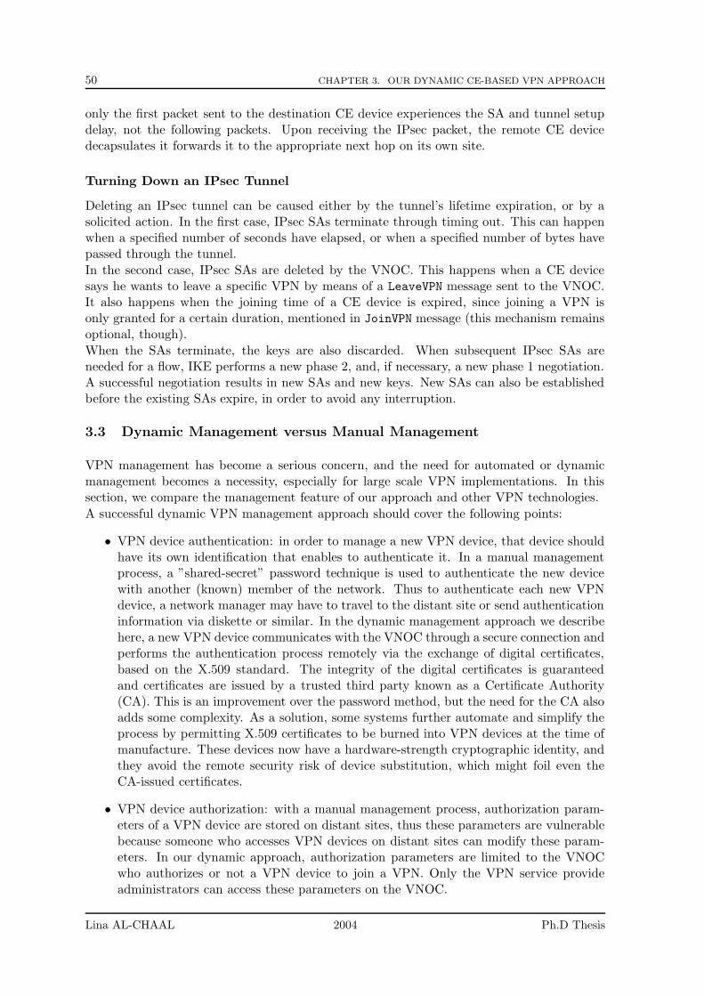
50 CHAPTER 3. OUR DYNAMIC CE-BASED VPN APPROACH
only the first packet sent to the destination CE device experiences the SA and tunnel setupdelay, not the following packets. Upon receiving the IPsec packet, the remote CE devicedecapsulates it forwards it to the appropriate next hop on its own site.
Turning Down an IPsec Tunnel
Deleting an IPsec tunnel can be caused either by the tunnel’s lifetime expiration, or by asolicited action. In the first case, IPsec SAs terminate through timing out. This can happenwhen a specified number of seconds have elapsed, or when a specified number of bytes havepassed through the tunnel.
In the second case, IPsec SAs are deleted by the VNOC. This happens when a CE devicesays he wants to leave a specific VPN by means of a LeaveVPN message sent to the VNOC.It also happens when the joining time of a CE device is expired, since joining a VPN isonly granted for a certain duration, mentioned in JoinVPN message (this mechanism remainsoptional, though).
When the SAs terminate, the keys are also discarded. When subsequent IPsec SAs areneeded for a flow, IKE performs a new phase 2, and, if necessary, a new phase 1 negotiation.A successful negotiation results in new SAs and new keys. New SAs can also be establishedbefore the existing SAs expire, in order to avoid any interruption.
3.3 Dynamic Management versus Manual Management
VPN management has become a serious concern, and the need for automated or dynamicmanagement becomes a necessity, especially for large scale VPN implementations. In thissection, we compare the management feature of our approach and other VPN technologies.
A successful dynamic VPN management approach should cover the following points:
• VPN device authentication: in order to manage a new VPN device, that device shouldhave its own identification that enables to authenticate it. In a manual managementprocess, a ”shared-secret” password technique is used to authenticate the new devicewith another (known) member of the network. Thus to authenticate each new VPNdevice, a network manager may have to travel to the distant site or send authenticationinformation via diskette or similar. In the dynamic management approach we describehere, a new VPN device communicates with the VNOC through a secure connection andperforms the authentication process remotely via the exchange of digital certificates,based on the X.509 standard. The integrity of the digital certificates is guaranteedand certificates are issued by a trusted third party known as a Certificate Authority(CA). This is an improvement over the password method, but the need for the CA alsoadds some complexity. As a solution, some systems further automate and simplify theprocess by permitting X.509 certificates to be burned into VPN devices at the time ofmanufacture. These devices now have a hardware-strength cryptographic identity, andthey avoid the remote security risk of device substitution, which might foil even theCA-issued certificates.
• VPN device authorization: with a manual management process, authorization param-eters of a VPN device are stored on distant sites, thus these parameters are vulnerablebecause someone who accesses VPN devices on distant sites can modify these param-eters. In our dynamic approach, authorization parameters are limited to the VNOCwho authorizes or not a VPN device to join a VPN. Only the VPN service provideadministrators can access these parameters on the VNOC.
Lina AL-CHAAL 2004 Ph.D Thesis
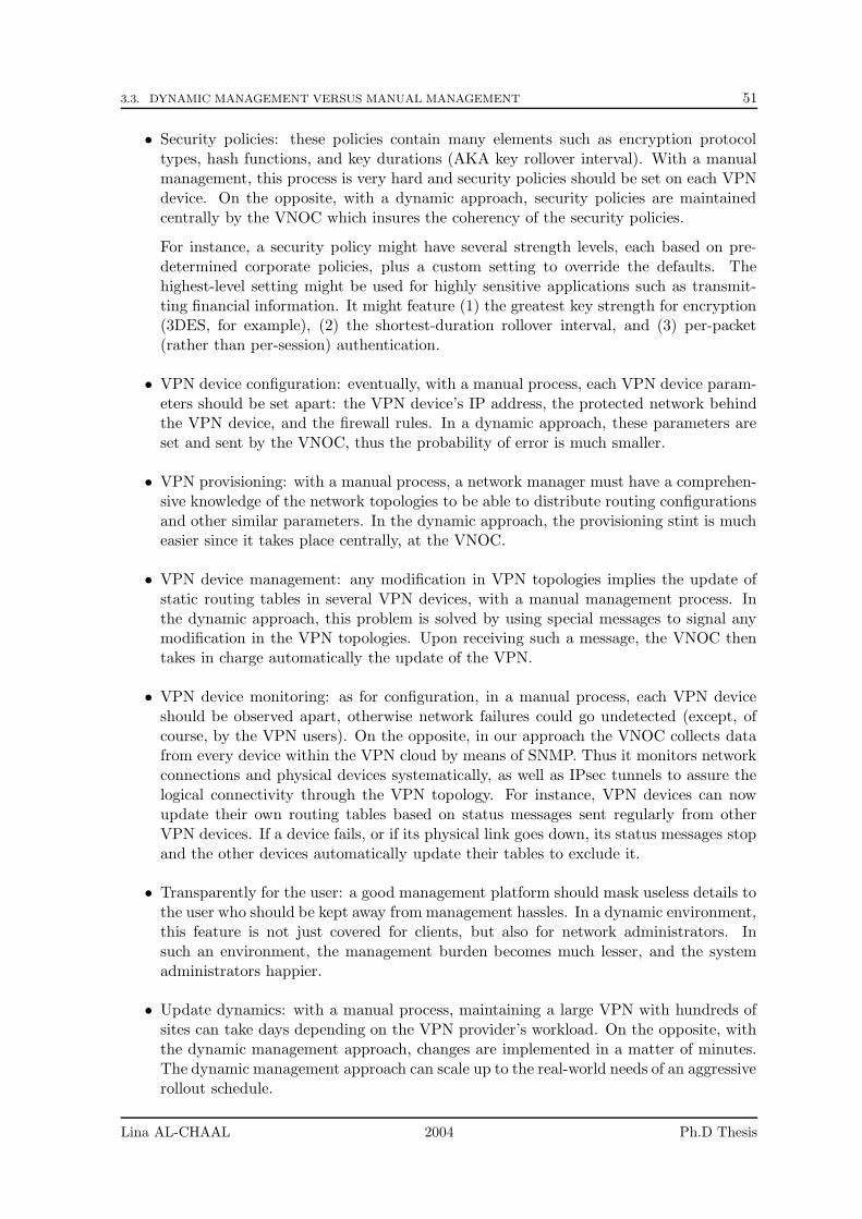
3.3. DYNAMIC MANAGEMENT VERSUS MANUAL MANAGEMENT 51
• Security policies: these policies contain many elements such as encryption protocoltypes, hash functions, and key durations (AKA key rollover interval). With a manualmanagement, this process is very hard and security policies should be set on each VPNdevice. On the opposite, with a dynamic approach, security policies are maintainedcentrally by the VNOC which insures the coherency of the security policies.
For instance, a security policy might have several strength levels, each based on pre-determined corporate policies, plus a custom setting to override the defaults. Thehighest-level setting might be used for highly sensitive applications such as transmit-ting financial information. It might feature (1) the greatest key strength for encryption(3DES, for example), (2) the shortest-duration rollover interval, and (3) per-packet(rather than per-session) authentication.
• VPN device configuration: eventually, with a manual process, each VPN device param-eters should be set apart: the VPN device’s IP address, the protected network behindthe VPN device, and the firewall rules. In a dynamic approach, these parameters areset and sent by the VNOC, thus the probability of error is much smaller.
• VPN provisioning: with a manual process, a network manager must have a comprehen-sive knowledge of the network topologies to be able to distribute routing configurationsand other similar parameters. In the dynamic approach, the provisioning stint is mucheasier since it takes place centrally, at the VNOC.
• VPN device management: any modification in VPN topologies implies the update ofstatic routing tables in several VPN devices, with a manual management process. Inthe dynamic approach, this problem is solved by using special messages to signal anymodification in the VPN topologies. Upon receiving such a message, the VNOC thentakes in charge automatically the update of the VPN.
• VPN device monitoring: as for configuration, in a manual process, each VPN deviceshould be observed apart, otherwise network failures could go undetected (except, ofcourse, by the VPN users). On the opposite, in our approach the VNOC collects datafrom every device within the VPN cloud by means of SNMP. Thus it monitors networkconnections and physical devices systematically, as well as IPsec tunnels to assure thelogical connectivity through the VPN topology. For instance, VPN devices can nowupdate their own routing tables based on status messages sent regularly from otherVPN devices. If a device fails, or if its physical link goes down, its status messages stopand the other devices automatically update their tables to exclude it.
• Transparently for the user: a good management platform should mask useless details tothe user who should be kept away from management hassles. In a dynamic environment,this feature is not just covered for clients, but also for network administrators. Insuch an environment, the management burden becomes much lesser, and the systemadministrators happier.
• Update dynamics: with a manual process, maintaining a large VPN with hundreds ofsites can take days depending on the VPN provider’s workload. On the opposite, withthe dynamic management approach, changes are implemented in a matter of minutes.The dynamic management approach can scale up to the real-world needs of an aggressiverollout schedule.
Lina AL-CHAAL 2004 Ph.D Thesis

52 CHAPTER 3. OUR DYNAMIC CE-BASED VPN APPROACH
3.4 Implementation Details
In this section we give an overview of the technical components that form the NOS.
The VNOC Architecture is subdivided into two technical areas which, by extension, arealso called architectures: the System of Exploitation Services (SES), and the System ofManagement Service (SMS) (figure 11.4). The relationships between the VNOC componentsand the other NOS components is also shown in this figure.
SMSSES
APIGUI
Configurations policies management console
Web based policy XML events
CE device
The Technical Components of the NOS
CA server
The N
OS
The VNOC
Action code
Action code
Policy Handler
Policy HandlerEvent
Notification
Policyrepository
Figure 3.5. Technical Components of the NOS
3.4.1 The SMS Architecture
Essentially, the SMS has four different roles:
• It takes in charge the integration with the CE devices.
• It generates configuration policies related to the information it gets from the SES com-ponent and the information stored in the database server.
• It offers an SSH service to secure communications with CE devices.
• It also offers a DNS service to manage domains’ names.
The SMS is a multi-threaded server. Services in this server are programmed in C language.
3.4.2 The SES Architecture
The SES is the principal interface of the NOS, since CE devices and the web console used inthe initial phase exchange data with the NOS through the SES. The SES has two essentialparts:
Lina AL-CHAAL 2004 Ph.D Thesis
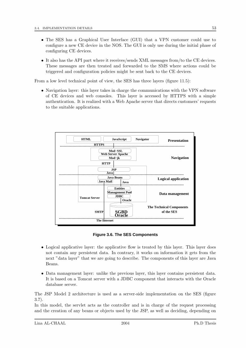
3.4. IMPLEMENTATION DETAILS 53
• The SES has a Graphical User Interface (GUI) that a VPN customer could use toconfigure a new CE device in the NOS. The GUI is only use during the initial phase ofconfiguring CE devices.
• It also has the API part where it receives/sends XML messages from/to the CE devices.These messages are then treated and forwarded to the SMS where actions could betriggered and configuration policies might be sent back to the CE devices.
From a low level technical point of view, the SES has three layers (figure 11.5):
• Navigation layer: this layer takes in charge the communications with the VPN softwareof CE devices and web consoles. This layer is accessed by HTTPS with a simpleauthentication. It is realized with a Web Apache server that directs customers’ requeststo the suitable applications.
NavigatorHTML JavaScript
Mod−SSL
Mod−jkWeb Server Apache
JSP
Java BeansJava Mail
The Internet
Presentation
Logical application
Navigation
Data managementManagement PoolEntities
JDBCTomcat Server
The Technical Components of the SES
HTTPS
HTTP
Java
Java
Oracle
SMTPOracleSGBD
Figure 3.6. The SES Components
• Logical applicative layer: the applicative flow is treated by this layer. This layer doesnot contain any persistent data. In contrary, it works on information it gets from thenext ”data layer” that we are going to describe. The components of this layer are JavaBeans.
• Data management layer: unlike the previous layer, this layer contains persistent data.It is based on a Tomcat server with a JDBC component that interacts with the Oracledatabase server.
The JSP Model 2 architecture is used as a server-side implementation on the SES (figure3.7).In this model, the servlet acts as the controller and is in charge of the request processingand the creation of any beans or objects used by the JSP, as well as deciding, depending on
Lina AL-CHAAL 2004 Ph.D Thesis
54 CHAPTER 3. OUR DYNAMIC CE-BASED VPN APPROACH
View JSP
Request
Reply
Forward
Client
Instantiate
Use
ModelJavaBean
Controller/Dispatcher Servlet
JSP Model 2 in the SES
BaseData
Figure 3.7. JSP Model 2 in the SES
the customer’s actions, which JSP page to forward the request to. The Java Bean object iscreated regarding the parameters sent through the URL or the customer’s request. There isno processing logic within the JSP page itself. The JSP is simply responsible for retrievingany objects or beans that may have been previously created by the servlet, and extractingthe dynamic content from that servlet for insertion within static templates.Customers are authenticated by the validation of login/passwords in the customers’ requests.The Tomcat server takes in charge this authentication service with the help of the JDBCdriver.
3.5 Features of our Approach: a Summary
To summarize, our approach has several distinctive features:
• ISP Independence: this service is provided by a VPN service provider independent ofany ISP. This is a major asset since it does not create any ISP dependency ( ISPscan change almost transparently) and enables VPN creations between sites connectedthrough different ISPs to the Internet. This is a major asset over other VPN solutionsprovided by ISPs that heavily rely on their own routing infrastructure.
• Simple centralized approach: the presence of a centralized VNOC greatly simplifies theconfiguration, management and possibly billing aspects.
• Relying on well-known building blocks: security is always done on a point-to-pointbasis, using well known security protocols like IPsec (site-site) and SSL (site-VNOC).
• Fully dynamic approach: each CE device sends dynamic requests to the VNOC tojoin/leave a VPN. Those dynamic requests are done on behalf of clients depending ontheir own needs.
• Many topologies are possible for site-to-site communications: if we assume by defaultthat a star topology, centered on the service provider, is created, this is not compulsoryand other schemes are possible for other communication scenarios. For instance [3]introduces the Routed VPN (or VPRN) concept whereby CEs can route packets betweenvarious VPN branches.
• Well-managed system: this approach offers an access mechanism to authenticate andauthorize users before they can benefit from the VPN service. It also provides a provi-sioning tool for the subscription, management, monitoring and billing processes.
Lina AL-CHAAL 2004 Ph.D Thesis
3.5. FEATURES OF OUR APPROACH: A SUMMARY 55
Since VPN configuration and topology are highly dependent upon a customer’s orga-nization, the CE device provisioning must address a broad range of customer specificrequirements. To ensure that these devices and protocols are provisioned consistentlyand correctly, web technologies like the XML language are the best candidate to defineconfiguration policies in a standard way (this will be discussed in chapter 6). In thisway, all customers information are defined in standard language and stored into a datainformation repository (e.g. LDAP) within the NOS. When a customer’s informationis needed, in order to be applied to a CE, the VNOC translates this information intoCE specific configurations.
In the next part of this thesis, we analyze the benefits of this approach into several domains.We first show how we can use it to offer group communication services over the Internet ina secure and cost-effective environment. We also show how easily we can secure and manageweb services due to our approach. Finally we describe how we can extend this approachto achieve load balancing at the customer’s side when the number of VPNs handled by thecustomer’s CE device is increased.
Lina AL-CHAAL 2004 Ph.D Thesis

56 CHAPTER 3. OUR DYNAMIC CE-BASED VPN APPROACH
Lina AL-CHAAL 2004 Ph.D Thesis
Part II
Some Contributions for theCE-based VPN Approach
57

Chapter 4
Basic Group CommunicationServices
Contents
4.1 Background . . . . . . . . . . . . . . . . . . . . . . . . . . . . . . . . 60
4.1.1 Limitations of IETF Solutions for Supporting Multicast over VPNs . 60
4.1.2 Our Approach for Secure Group Communications . . . . . . . . . . . 61
4.2 Our Approach: IVGMP Architecture . . . . . . . . . . . . . . . . 63
4.2.1 The Virtual Router Concept . . . . . . . . . . . . . . . . . . . . . . 63
4.2.2 IVGMP Detailed Description . . . . . . . . . . . . . . . . . . . . . . 63
4.2.3 IVGMP Critical Appraisal . . . . . . . . . . . . . . . . . . . . . . . . 65
4.3 Implementation Aspects . . . . . . . . . . . . . . . . . . . . . . . . 66
4.4 Partial Conclusions . . . . . . . . . . . . . . . . . . . . . . . . . . . 67
As the Internet grows, communication needs evolve and customers ask for more and morenetwork services. The programmable network approach is one possible solution to quicklyadapt existing infrastructures to new requirements. At the same time, group communicationis unavoidable when dealing with collaborative work and bulk data distribution applications.Although the deployment of native multicast routing is well behind expectation [29], theimportant activity around application level multicasting proves there is an important need[17]. But two aspects, that often lack, are the security of communications and the dynamicmanagement of group communication members.
In this chapter:
• We show how programmable networking can be exploited within a VPN environmentto offer a secure group communication service across the Internet. In particular, webuild a group communication service on top of a fully secure IPVPN environment withthe help of our CE-based VPN approach.
• We show how our approach offloads security, management and administration hasslesfrom the multicast members.
• And we propose a new simple Internet VPN Group Management Protocol, IVGMP, asan alternative to traditional multicast routing protocols. We detail our proposal, theIVGMP protocol and we give some insight on its implementation.
59
60 CHAPTER 4. BASIC GROUP COMMUNICATION SERVICES
4.1 Background
4.1.1 Limitations of IETF Solutions for Supporting Multicast over VPNs
Two categories of related works are worth mentioning here:
Multicast study over VPNs
Our work also departs from that carried out in the PPVPN IETF working group where theVPN Service Provider, in addition to providing a VPN solution, also masters the core networkand is an ISP. In general, group communication solutions developed by PPVPN providerscan easily and efficiently take advantage of their own provider equipments (e.g. IP routersor MPLS-enabled infrastructure) to offer multicast-capable VPNs [70]. In our case the twoentities, the VPN SP and the ISP, are different entities. It avoids ISP dependencies andenables to set up a VPN across sites connected to the Internet via different ISPs, withoutrequiring preliminary ISP agreements and mutual confidence.Also many efforts have been done recently in the L3VPN working group in order for IPmulticast traffic within L3VPNs, in particular within BGP/MPLS IPVPNs, to travel from oneVPN site to another [75]. All current work specify protocols to enable multicast traffic throughthe service providers’ core networks and allow providers to interconnect customers mutlicastdomains [8]. All proposals assume that the service provider network already supports nativeIP multicast forwarding [55]. Otherwise no solution is provided to enable multicast over sucha VPN. Few implementations (e.g. Cisco and Juniper) are commercially available today toprovide multicast in the providers core networks.The draft [75] extends RFC 2547 VPN functionality to support multicast data transport.The key features of this approach are as follows:
• A multicast domain is a set of VPN Routing and Forwarding tables (VRFs) located onthe PE devices and associated with interfaces that can send multicast traffic to eachother. A VRF can belong to more than one multicast domain.
• Each multicast domain is associated with an otherwise unused multicast group addressfrom the address space of the service provider network.
• A service provider network instance of PIM-SM runs on each PE router. These PErouters join the service provider multicast groups corresponding to the multicast do-mains to which they are connected.
In this approach there is a multicast tree for each multicast domain within the service providernetwork. This multicast tree is referred to as the multicast tunnel for the domain. Customermulticast data is transmitted across the service provider network, after being encapsulatedwithin a packet whose outer destination address is the per-domain multicast group address(since the inner packet will have a customer site specific multicast group address). Thisencapsulation could use MPLS tunnels or GRE.Each PE router runs a per-VRF instance of PIM-SM that communicates with the CE device.This PIM-SM instance treats the multicast tunnel as a multidrop interface that reachesall of the other PE routers that are associated with this domain. If a single VRF is inseveral multicast domains, then PIM-SM requires additional information to make the choiceof which multicast tunnel to use for which customer space multicast groups. This informationis provided by an out-of-band mechanism. Note that from the point of view of the CE devices,there is no change to PIM-SM or packet forwarding mechanism.
Lina AL-CHAAL 2004 Ph.D Thesis
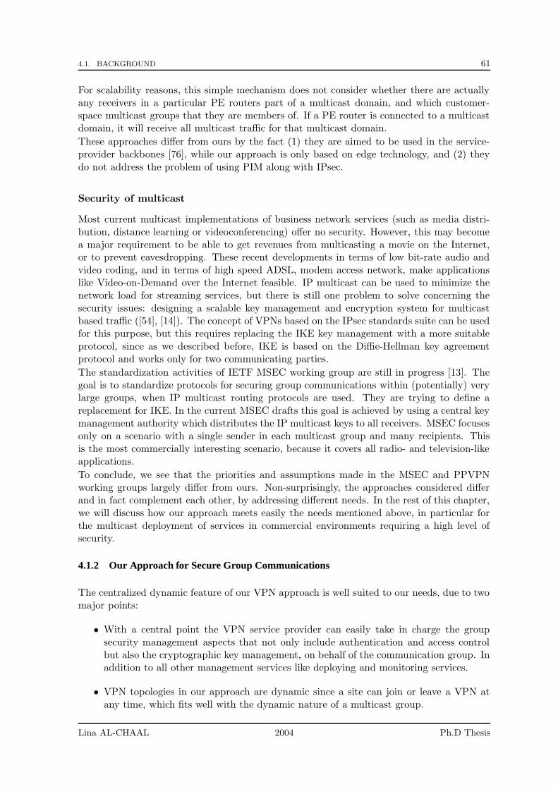
4.1. BACKGROUND 61
For scalability reasons, this simple mechanism does not consider whether there are actuallyany receivers in a particular PE routers part of a multicast domain, and which customer-space multicast groups that they are members of. If a PE router is connected to a multicastdomain, it will receive all multicast traffic for that multicast domain.
These approaches differ from ours by the fact (1) they are aimed to be used in the service-provider backbones [76], while our approach is only based on edge technology, and (2) theydo not address the problem of using PIM along with IPsec.
Security of multicast
Most current multicast implementations of business network services (such as media distri-bution, distance learning or videoconferencing) offer no security. However, this may becomea major requirement to be able to get revenues from multicasting a movie on the Internet,or to prevent eavesdropping. These recent developments in terms of low bit-rate audio andvideo coding, and in terms of high speed ADSL, modem access network, make applicationslike Video-on-Demand over the Internet feasible. IP multicast can be used to minimize thenetwork load for streaming services, but there is still one problem to solve concerning thesecurity issues: designing a scalable key management and encryption system for multicastbased traffic ([54], [14]). The concept of VPNs based on the IPsec standards suite can be usedfor this purpose, but this requires replacing the IKE key management with a more suitableprotocol, since as we described before, IKE is based on the Diffie-Hellman key agreementprotocol and works only for two communicating parties.
The standardization activities of IETF MSEC working group are still in progress [13]. Thegoal is to standardize protocols for securing group communications within (potentially) verylarge groups, when IP multicast routing protocols are used. They are trying to define areplacement for IKE. In the current MSEC drafts this goal is achieved by using a central keymanagement authority which distributes the IP multicast keys to all receivers. MSEC focusesonly on a scenario with a single sender in each multicast group and many recipients. Thisis the most commercially interesting scenario, because it covers all radio- and television-likeapplications.
To conclude, we see that the priorities and assumptions made in the MSEC and PPVPNworking groups largely differ from ours. Non-surprisingly, the approaches considered differand in fact complement each other, by addressing different needs. In the rest of this chapter,we will discuss how our approach meets easily the needs mentioned above, in particular forthe multicast deployment of services in commercial environments requiring a high level ofsecurity.
4.1.2 Our Approach for Secure Group Communications
The centralized dynamic feature of our VPN approach is well suited to our needs, due to twomajor points:
• With a central point the VPN service provider can easily take in charge the groupsecurity management aspects that not only include authentication and access controlbut also the cryptographic key management, on behalf of the communication group. Inaddition to all other management services like deploying and monitoring services.
• VPN topologies in our approach are dynamic since a site can join or leave a VPN atany time, which fits well with the dynamic nature of a multicast group.
Lina AL-CHAAL 2004 Ph.D Thesis
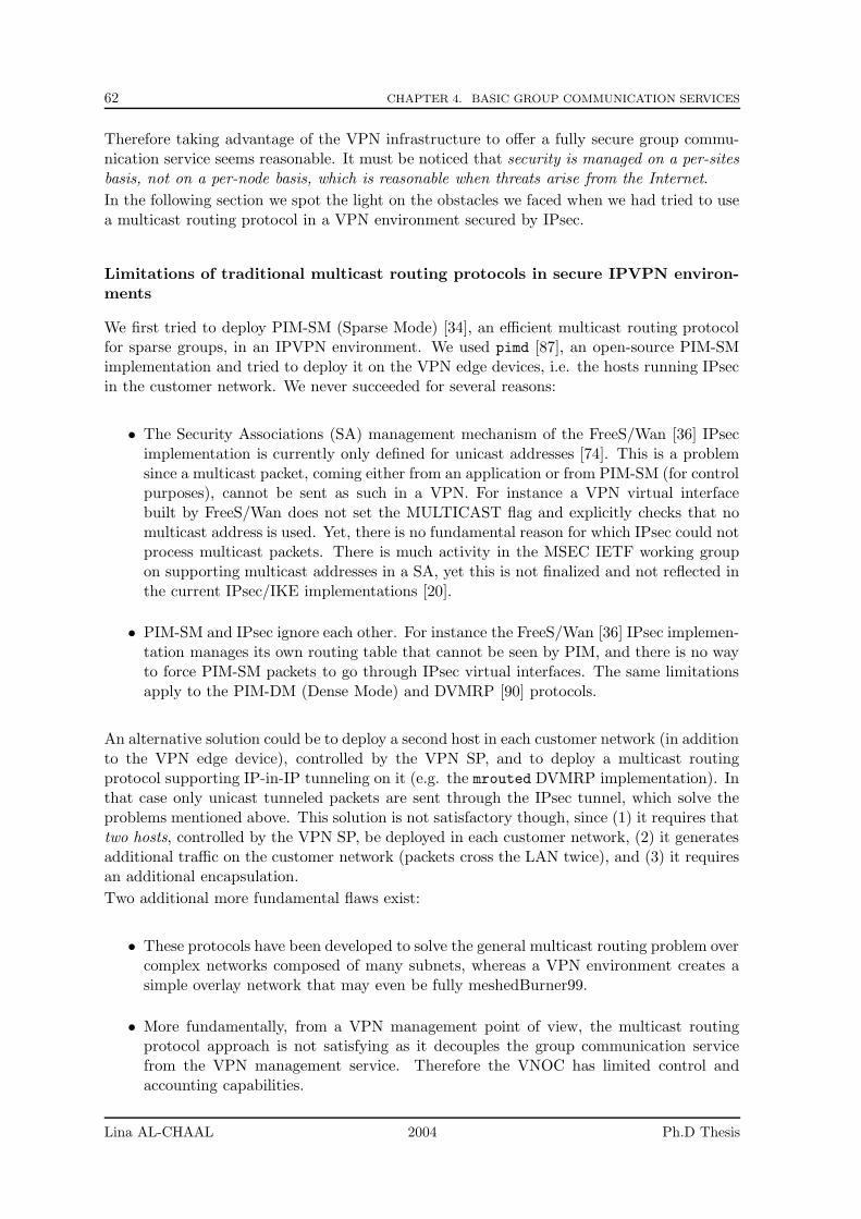
62 CHAPTER 4. BASIC GROUP COMMUNICATION SERVICES
Therefore taking advantage of the VPN infrastructure to offer a fully secure group commu-nication service seems reasonable. It must be noticed that security is managed on a per-sitesbasis, not on a per-node basis, which is reasonable when threats arise from the Internet.
In the following section we spot the light on the obstacles we faced when we had tried to usea multicast routing protocol in a VPN environment secured by IPsec.
Limitations of traditional multicast routing protocols in secure IPVPN environ-ments
We first tried to deploy PIM-SM (Sparse Mode) [34], an efficient multicast routing protocolfor sparse groups, in an IPVPN environment. We used pimd [87], an open-source PIM-SMimplementation and tried to deploy it on the VPN edge devices, i.e. the hosts running IPsecin the customer network. We never succeeded for several reasons:
• The Security Associations (SA) management mechanism of the FreeS/Wan [36] IPsecimplementation is currently only defined for unicast addresses [74]. This is a problemsince a multicast packet, coming either from an application or from PIM-SM (for controlpurposes), cannot be sent as such in a VPN. For instance a VPN virtual interfacebuilt by FreeS/Wan does not set the MULTICAST flag and explicitly checks that nomulticast address is used. Yet, there is no fundamental reason for which IPsec could notprocess multicast packets. There is much activity in the MSEC IETF working groupon supporting multicast addresses in a SA, yet this is not finalized and not reflected inthe current IPsec/IKE implementations [20].
• PIM-SM and IPsec ignore each other. For instance the FreeS/Wan [36] IPsec implemen-tation manages its own routing table that cannot be seen by PIM, and there is no wayto force PIM-SM packets to go through IPsec virtual interfaces. The same limitationsapply to the PIM-DM (Dense Mode) and DVMRP [90] protocols.
An alternative solution could be to deploy a second host in each customer network (in additionto the VPN edge device), controlled by the VPN SP, and to deploy a multicast routingprotocol supporting IP-in-IP tunneling on it (e.g. the mrouted DVMRP implementation). Inthat case only unicast tunneled packets are sent through the IPsec tunnel, which solve theproblems mentioned above. This solution is not satisfactory though, since (1) it requires thattwo hosts, controlled by the VPN SP, be deployed in each customer network, (2) it generatesadditional traffic on the customer network (packets cross the LAN twice), and (3) it requiresan additional encapsulation.
Two additional more fundamental flaws exist:
• These protocols have been developed to solve the general multicast routing problem overcomplex networks composed of many subnets, whereas a VPN environment creates asimple overlay network that may even be fully meshedBurner99.
• More fundamentally, from a VPN management point of view, the multicast routingprotocol approach is not satisfying as it decouples the group communication servicefrom the VPN management service. Therefore the VNOC has limited control andaccounting capabilities.
Lina AL-CHAAL 2004 Ph.D Thesis
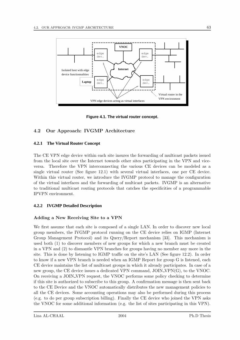
4.2. OUR APPROACH: IVGMP ARCHITECTURE 63
edgedev.
edgedev.
edgedev.
edgedev.
VPN environment
VNOC
Internet
Laptop
Virtual router in the
device functionnalities
Isolated host with edge
VPN edge devices acting as virtual interfaces
Figure 4.1. The virtual router concept.
4.2 Our Approach: IVGMP Architecture
4.2.1 The Virtual Router Concept
The CE VPN edge device within each site insures the forwarding of multicast packets issuedfrom the local site over the Internet towards other sites participating in the VPN and vice-versa. Therefore the VPN interconnecting the various CE devices can be modeled as asingle virtual router (See figure 12.1) with several virtual interfaces, one per CE device.Within this virtual router, we introduce the IVGMP protocol to manage the configurationof the virtual interfaces and the forwarding of multicast packets. IVGMP is an alternativeto traditional multicast routing protocols that catches the specificities of a programmableIPVPN environment.
4.2.2 IVGMP Detailed Description
Adding a New Receiving Site to a VPN
We first assume that each site is composed of a single LAN. In order to discover new localgroup members, the IVGMP protocol running on the CE device relies on IGMP (InternetGroup Management Protocol) and its Query/Report mechanism [33]. This mechanism isused both (1) to discover members of new groups for which a new branch must be createdin a VPN and (2) to dismantle VPN branches for groups having no member any more in thesite. This is done by listening to IGMP traffic on the site’s LAN (See figure 12.2). In orderto know if a new VPN branch is needed when an IGMP Report for group G is listened, eachCE device maintains the list of multicast groups in which it already participates. In case of anew group, the CE device issues a dedicated VPN command, JOIN VPN(G), to the VNOC.On receiving a JOIN VPN request, the VNOC performs some policy checking to determineif this site is authorized to subscribe to this group. A confirmation message is then sent backto the CE Device and the VNOC automatically distributes the new management policies toall the CE devices. Some accounting operations may also be performed during this process(e.g. to do per group subscription billing). Finally the CE device who joined the VPN asksthe VNOC for some additional information (e.g. the list of sites participating in this VPN).
Lina AL-CHAAL 2004 Ph.D Thesis
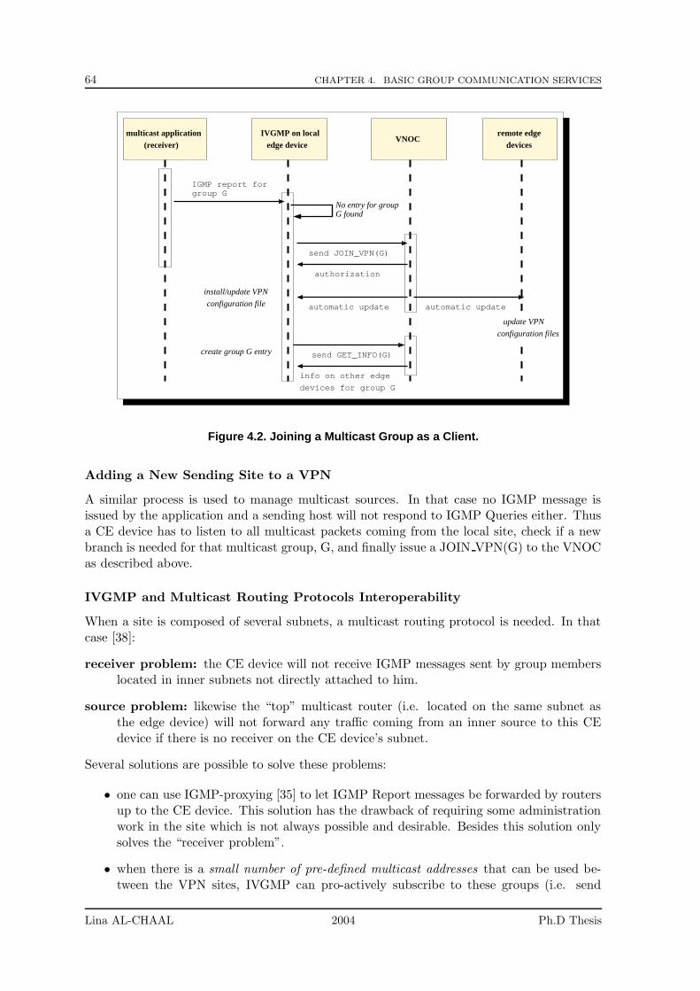
64 CHAPTER 4. BASIC GROUP COMMUNICATION SERVICES
devices for group G
info on other edge
No entry for groupG found
IVGMP on localedge device
VNOCdevices
remote edgemulticast application(receiver)
authorization
send JOIN_VPN(G)
automatic update
send GET_INFO(G)
configuration file
install/update VPN
create group G entry
group GIGMP report for
automatic update
configuration files
update VPN
Figure 4.2. Joining a Multicast Group as a Client.
Adding a New Sending Site to a VPN
A similar process is used to manage multicast sources. In that case no IGMP message isissued by the application and a sending host will not respond to IGMP Queries either. Thusa CE device has to listen to all multicast packets coming from the local site, check if a newbranch is needed for that multicast group, G, and finally issue a JOIN VPN(G) to the VNOCas described above.
IVGMP and Multicast Routing Protocols Interoperability
When a site is composed of several subnets, a multicast routing protocol is needed. In thatcase [38]:
receiver problem: the CE device will not receive IGMP messages sent by group memberslocated in inner subnets not directly attached to him.
source problem: likewise the “top” multicast router (i.e. located on the same subnet asthe edge device) will not forward any traffic coming from an inner source to this CEdevice if there is no receiver on the CE device’s subnet.
Several solutions are possible to solve these problems:
• one can use IGMP-proxying [35] to let IGMP Report messages be forwarded by routersup to the CE device. This solution has the drawback of requiring some administrationwork in the site which is not always possible and desirable. Besides this solution onlysolves the “receiver problem”.
• when there is a small number of pre-defined multicast addresses that can be used be-tween the VPN sites, IVGMP can pro-actively subscribe to these groups (i.e. send
Lina AL-CHAAL 2004 Ph.D Thesis
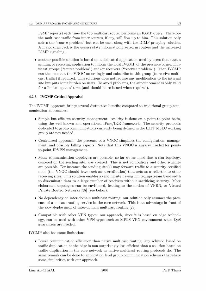
4.2. OUR APPROACH: IVGMP ARCHITECTURE 65
IGMP reports) each time the top multicast router performs an IGMP query. Thereforethe multicast traffic from inner sources, if any, will flow up to him. This solution onlysolves the “source problem” but can be used along with the IGMP-proxying solution.A major drawback is the useless state information created in routers and the increasedIGMP signaling.
• another possible solution is based on a dedicated application used by users that start asending or receiving application to inform the local IVGMP of the presence of new mul-ticast groups (“source problem”) and/or receivers (“receiver problem”). Then IVGMPcan then contact the VNOC accordingly and subscribe to this group (to receive multi-cast traffic) if required. This solutions does not require any modification to the internalsite but puts some burden on users. To avoid problems, the announcement is only validfor a limited span of time (and should be re-issued when required).
4.2.3 IVGMP Critical Appraisal
The IVGMP approach brings several distinctive benefits compared to traditional group com-munication approaches:
• Simple but efficient security management: security is done on a point-to-point basis,using the well known and operational IPsec/IKE framework. The security protocolsdedicated to group communications currently being defined in the IETF MSEC workinggroup are not needed.
• Centralized approach: the presence of a VNOC simplifies the configuration, manage-ment, and possibly billing aspects. Note that this VNOC is anyway needed for point-to-point IPVPN management.
• Many communication topologies are possible: so far we assumed that a star topology,centered on the sending site, was created. This is not compulsory and other schemesare possible. For instance the sending site(s) may forward traffic to a security certifiednode (the VNOC should have such an accreditation) that acts as a reflector to otherreceiving sites. This solution enables a sending site having limited upstream bandwidthto disseminate data to a large number of receivers without sacrificing security. Moreelaborated topologies can be envisioned, leading to the notion of VPRN, or VirtualPrivate Routed Networks [38] (see below).
• No dependency on inter-domain multicast routing: our solution only assumes the pres-ence of a unicast routing service in the core network. This is an advantage in front ofthe slow deployment of inter-domain multicast routing [29].
• Compatible with other VPN types: our approach, since it is based on edge technol-ogy, can be used with other VPN types such as MPLS VPN environment when QoSguarantees are needed.
IVGMP also has some limitations:
• Lower communication efficiency than native multicast routing: any solution based ontraffic duplication at the edge is non-surprisingly less efficient than a solution based ontraffic duplication in the core network as native multicast routing protocols do. Thesame remark can be done to application level group communication schemes that sharesome similarities with our approach.
Lina AL-CHAAL 2004 Ph.D Thesis
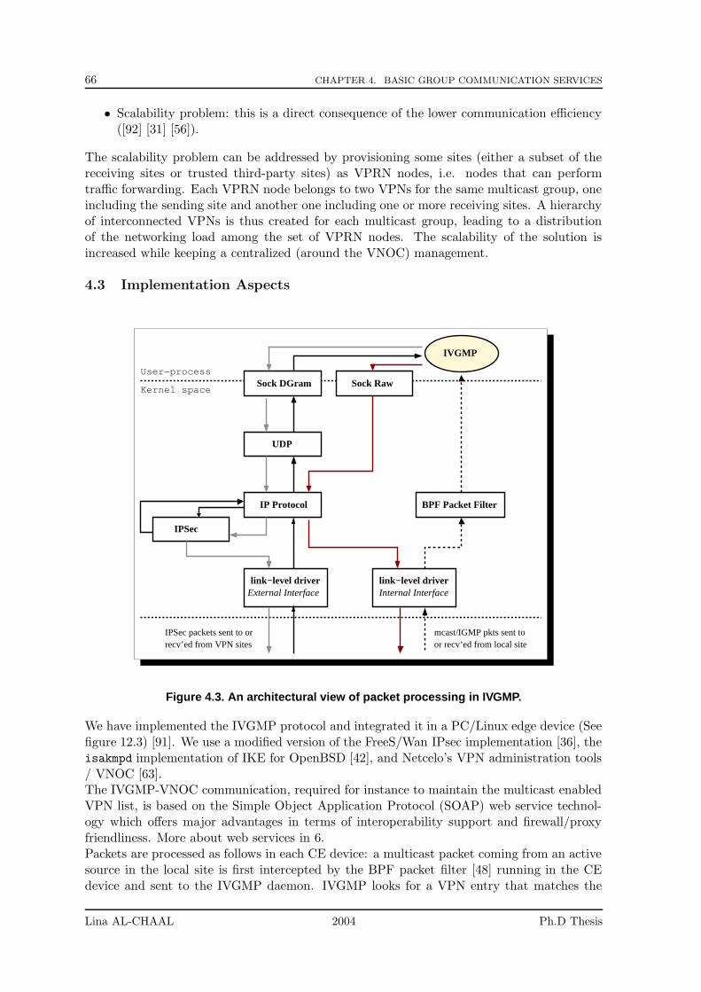
66 CHAPTER 4. BASIC GROUP COMMUNICATION SERVICES
• Scalability problem: this is a direct consequence of the lower communication efficiency([92] [31] [56]).
The scalability problem can be addressed by provisioning some sites (either a subset of thereceiving sites or trusted third-party sites) as VPRN nodes, i.e. nodes that can performtraffic forwarding. Each VPRN node belongs to two VPNs for the same multicast group, oneincluding the sending site and another one including one or more receiving sites. A hierarchyof interconnected VPNs is thus created for each multicast group, leading to a distributionof the networking load among the set of VPRN nodes. The scalability of the solution isincreased while keeping a centralized (around the VNOC) management.
4.3 Implementation Aspects
link−level driverExternal Interface
IP Protocol
UDP
Sock DGram
IPSec
Sock Raw
BPF Packet Filter
link−level driverInternal Interface
mcast/IGMP pkts sent toor recv’ed from local site
IPSec packets sent to orrecv’ed from VPN sites
Kernel space
User−process
IVGMP
Figure 4.3. An architectural view of packet processing in IVGMP.
We have implemented the IVGMP protocol and integrated it in a PC/Linux edge device (Seefigure 12.3) [91]. We use a modified version of the FreeS/Wan IPsec implementation [36], theisakmpd implementation of IKE for OpenBSD [42], and Netcelo’s VPN administration tools/ VNOC [63].The IVGMP-VNOC communication, required for instance to maintain the multicast enabledVPN list, is based on the Simple Object Application Protocol (SOAP) web service technol-ogy which offers major advantages in terms of interoperability support and firewall/proxyfriendliness. More about web services in 6.Packets are processed as follows in each CE device: a multicast packet coming from an activesource in the local site is first intercepted by the BPF packet filter [48] running in the CEdevice and sent to the IVGMP daemon. IVGMP looks for a VPN entry that matches the
Lina AL-CHAAL 2004 Ph.D Thesis
4.4. PARTIAL CONCLUSIONS 67
destination multicast address to decide whether or not the packet should be sent to the othersites. If an entry is found, a copy of the packet is encapsulated in a unicast UDP/IP datagramfor each remote site (we use a UDP encapsulation in the current prototype for simplicity),given to IPsec and sent through a tunnel to the remote CE device. In the other direction apacket coming from a remote VPN site is successively processed by IPsec, IP, UDP, and thenIVGMP. This latter finally injects the original multicast packet in the local site through araw socket.This implementation enabled us to validate the IVGMP concept. Some values were measuredrelated to the API used in the CE-VNOC communications 6. However other performance as-pects and possible optimizations are left for future work, we focus essentially on architecturalaspects.
4.4 Partial Conclusions
The approach discussed in this chapter fuses miscellaneous sparse technologies like IPVPNs,web services (SOAP), programmable networks, in the same melting pot to get out with asimple flexible way to offer fully secure group communication services over the Internet [5].We have described IVGMP, a new solution for offering a group communication service basedon the programmable IPVPN technology. The nature of this solution ensures its robustness,flexibility and full security. This solution departs from the traditional approach since itbrings a group communication service on top of a fully secure infrastructure rather than thecontrary.Finally, our approach shares some similarities with the Centralized Multicast (CM) approach[51]. In CM, the data forwarding and control functions are kept separated, and the controlpart is centralized in distinct control elements. The control elements are arranged in a two-level hierarchy within autonomous systems and are used to set up multicast trees. In ourapproach too, the control part is centralized in the VNOC. The major difference yet it thatCM does not address security.
Lina AL-CHAAL 2004 Ph.D Thesis

68 CHAPTER 4. BASIC GROUP COMMUNICATION SERVICES
Lina AL-CHAAL 2004 Ph.D Thesis
Chapter 5
Using Application Level Multicastfor Improved GroupCommunication Efficiency: theVPRN Concept
Contents
5.1 Background . . . . . . . . . . . . . . . . . . . . . . . . . . . . . . . . 70
5.1.1 Limitations of our CE-based VPN approach . . . . . . . . . . . . . . 70
5.1.2 The Benefits of the VPRN and Overlay Multicast Solutions . . . . . 71
5.2 Our Approach: The IVGMP/HBM Architecture . . . . . . . . . 72
5.2.1 General Architecture . . . . . . . . . . . . . . . . . . . . . . . . . . . 72
5.2.2 Detailed Description . . . . . . . . . . . . . . . . . . . . . . . . . . . 74
5.3 Performance Evaluations . . . . . . . . . . . . . . . . . . . . . . . . 75
5.3.1 Experimental Conditions . . . . . . . . . . . . . . . . . . . . . . . . 75
5.3.2 Metrics Considered . . . . . . . . . . . . . . . . . . . . . . . . . . . . 75
5.3.3 Results and Discussion . . . . . . . . . . . . . . . . . . . . . . . . . . 76
5.4 Partial Conclusions . . . . . . . . . . . . . . . . . . . . . . . . . . . 76
This chapter is a follow-up of the previous work on group communications in a VPN envi-ronment 4 and on application-level multicast.
In this chapter we show how to extend and optimize our approach discussed in the previouschapter, to offer full secure but efficient group communication service between several sites.This extension is based on two notions: the concept of Virtual Private Routed Network(VPRN) and an innovative application-level multicast protocol called Host-Based Multicast(HBM).
As we will discuss later the solution in this chapter is a step forward to overcome scalabilityissue regarding our previous solution in 4.
The rest of this chapter is organized as follows: section 5.1.2 gives a quick background anddetails both the concept of VPRN and the HBM overlay multicast proposal; section 5.2discusses the merge of the IVGMP and HBM protocols in order to create a multicast-enabled
69
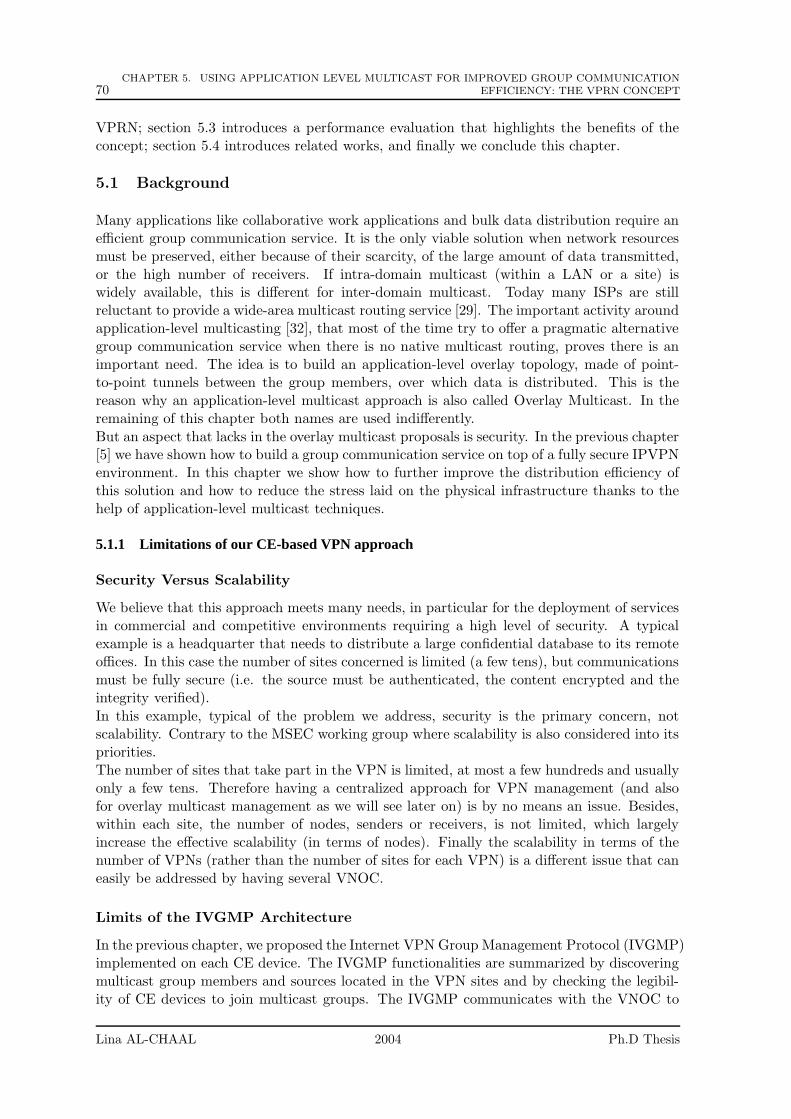
70CHAPTER 5. USING APPLICATION LEVEL MULTICAST FOR IMPROVED GROUP COMMUNICATION
EFFICIENCY: THE VPRN CONCEPT
VPRN; section 5.3 introduces a performance evaluation that highlights the benefits of theconcept; section 5.4 introduces related works, and finally we conclude this chapter.
5.1 Background
Many applications like collaborative work applications and bulk data distribution require anefficient group communication service. It is the only viable solution when network resourcesmust be preserved, either because of their scarcity, of the large amount of data transmitted,or the high number of receivers. If intra-domain multicast (within a LAN or a site) iswidely available, this is different for inter-domain multicast. Today many ISPs are stillreluctant to provide a wide-area multicast routing service [29]. The important activity aroundapplication-level multicasting [32], that most of the time try to offer a pragmatic alternativegroup communication service when there is no native multicast routing, proves there is animportant need. The idea is to build an application-level overlay topology, made of point-to-point tunnels between the group members, over which data is distributed. This is thereason why an application-level multicast approach is also called Overlay Multicast. In theremaining of this chapter both names are used indifferently.
But an aspect that lacks in the overlay multicast proposals is security. In the previous chapter[5] we have shown how to build a group communication service on top of a fully secure IPVPNenvironment. In this chapter we show how to further improve the distribution efficiency ofthis solution and how to reduce the stress laid on the physical infrastructure thanks to thehelp of application-level multicast techniques.
5.1.1 Limitations of our CE-based VPN approach
Security Versus Scalability
We believe that this approach meets many needs, in particular for the deployment of servicesin commercial and competitive environments requiring a high level of security. A typicalexample is a headquarter that needs to distribute a large confidential database to its remoteoffices. In this case the number of sites concerned is limited (a few tens), but communicationsmust be fully secure (i.e. the source must be authenticated, the content encrypted and theintegrity verified).
In this example, typical of the problem we address, security is the primary concern, notscalability. Contrary to the MSEC working group where scalability is also considered into itspriorities.The number of sites that take part in the VPN is limited, at most a few hundreds and usuallyonly a few tens. Therefore having a centralized approach for VPN management (and alsofor overlay multicast management as we will see later on) is by no means an issue. Besides,within each site, the number of nodes, senders or receivers, is not limited, which largelyincrease the effective scalability (in terms of nodes). Finally the scalability in terms of thenumber of VPNs (rather than the number of sites for each VPN) is a different issue that caneasily be addressed by having several VNOC.
Limits of the IVGMP Architecture
In the previous chapter, we proposed the Internet VPN Group Management Protocol (IVGMP)implemented on each CE device. The IVGMP functionalities are summarized by discoveringmulticast group members and sources located in the VPN sites and by checking the legibil-ity of CE devices to join multicast groups. The IVGMP communicates with the VNOC to
Lina AL-CHAAL 2004 Ph.D Thesis
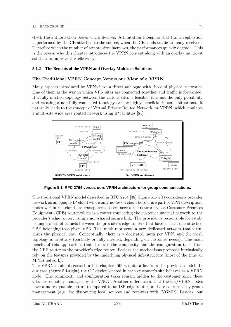
5.1. BACKGROUND 71
check the authorization issues of CE devices. A limitation though is that traffic replicationis performed by the CE attached to the source, when the CE sends traffic to many receivers.Therefore when the number of remote sites increases, the performances quickly degrade. Thisis the reason why this chapter introduces the VPRN concept along with an overlay multicastsolution to improve this efficiency.
5.1.2 The Benefits of the VPRN and Overlay Multicast Solutions
The Traditional VPRN Concept Versus our View of a VPRN
Many aspects introduced by VPNs have a direct analogue with those of physical networks.One of them is the way in which VPN sites are connected together and traffic is forwarded.If a fully meshed topology between the various sites is feasible, it is not the only possibilityand creating a non-fully connected topology can be highly beneficial in some situations. Itnaturally leads to the concept of Virtual Private Routed Network, or VPRN, which emulatesa multi-site wide area routed network using IP facilities [81].
ISP edgerouter
ISP edgerouter
ISP edgerouter
CPE
CPE
CPE
clientsite
ED/ivgmp
source
ED/ivgmp
sourceclient site
VNOC/RP
ED/ivgmp
sourceclient site
Unsecure Internetbackbone
ISP backboneIP tunnelIP tunnel
IP tunnel
client site
secure link
secure link
client site
VPN service provider
RFC2764 VPRN architecture Our VPRN architecture
client site
IPSec tunnel
IPSec tunnel
Figure 5.1. RFC 2764 versus ours VPRN architecture for group communications.
The traditional VPRN model described in RFC 2764 [38] (figure 5.1-left) considers a providernetwork as an opaque IP cloud where only nodes on cloud border are part of VPN description;nodes within the cloud are transparent. Users access the network via a Customer PremisesEquipment (CPE) router,which is a router connecting the customer internal network to theprovider’s edge router, using a non-shared secure link. The provider is responsible for estab-lishing a mesh of tunnels between the provider’s edge routers that have at least one attachedCPE belonging to a given VPN. This mesh represents a new dedicated network that virtu-alizes the physical one. Conceptually, there is a dedicated mesh per VPN, and the meshtopology is arbitrary (partially or fully meshed, depending on customer needs). The mainbenefit of this approach is that it moves the complexity and the configuration tasks fromthe CPE router to the provider’s edge router. Besides the mechanisms proposed intrinsicallyrely on the features provided by the underlying physical infrastructure (most of the time anMPLS network).The VPRN model discussed in this chapter differs quite a lot from the previous model. Inour case (figure 5.1-right) the CE device located in each customer’s site behaves as a VPRNnode. The complexity and configuration tasks remain hidden to the customer since theseCEs are remotely managed by the VNOC. Another difference is that the CE/VPRN nodeshave a more dynamic nature (compared to an ISP edge router) and are concerned by groupmanagement (e.g. by discovering local sources and receivers with IVGMP). Besides, our
Lina AL-CHAAL 2004 Ph.D Thesis
72CHAPTER 5. USING APPLICATION LEVEL MULTICAST FOR IMPROVED GROUP COMMUNICATION
EFFICIENCY: THE VPRN CONCEPT
VPRN architecture is built on top of a generic IP network, without making any assumptionon the underlying physical infrastructure. Likewise it does not need any ISP agreement whensites are connected through different ISPs, which is a big asset.
The Overlay Multicast Concept and the HBM Protocol
The usual Overlay Multicast goal is to offer an alternative to the lack of deployment of inter-domain multicast routing. Many protocols, largely different in their approach, have beendefined, but they all share some similarities that distinguish them from traditional multicastrouting [32]:
• A forwarding node in the overlay topology can be either a end-host (i.e. running theapplication), a dedicated server within a site, or a border router.
• With an overlay topology, the underlying physical topology is completely hidden. Adirected (or often undirected) virtual graph is created between all the nodes, and metricmeasurements taken between these nodes (or a subset).
• In traditional multicast, the membership knowledge is distributed in the multicastrouters. With an overlay multicast, group members are known either by a Rendez-vous Point (or RP), by the source, by everybody, or is distributed among members(e.g. for increased scalability).
• The overlay topology is potentially under complete control. In particular the topologycreation process is often optimized using the distance metrics collected between thenodes.
In [73] the Host-Based Multicast (HBM) protocol is defined. This protocol automaticallycreates a virtual overlay topology between the various group members, using point-to-pointUDP tunnels between them. Everything is under the control of a Rendez-vous Point, or RP.This RP knows the members, their features, and the communication costs between them. Heis responsible of the topology calculation and its dissemination among group members.The data distribution efficiency highly depends on the quality of the distribution tree. This isaddressed by the periodic node-to-node (in our case site-to-site) measurements performed byHBM nodes and that are communicated to the RP. This latter then create the distributiontopology, using the available metrics. If existing solvers can easily create an optimal topology,in practice the metric database only gives a partial, more or less outdated, view of thenetworking conditions. Yet we assume that the resulting topology is reasonably good. Bydefault, a shared shortest-path tree is created, but other topologies are possible, for instancea per-source tree when the application is known to be single-source.
5.2 Our Approach: The IVGMP/HBM Architecture
We have described so far the various concepts and protocols. In this section we describe howthey nicely fit with one another.
5.2.1 General Architecture
The VPN approach considered so far is centralized around the VNOC. Thanks to the IVGMPprotocol running on each CE device, the VNOC is also responsible of collecting and distribut-ing configuration policies and membership information (in terms of sites) for each multicast
Lina AL-CHAAL 2004 Ph.D Thesis
5.2. OUR APPROACH: THE IVGMP/HBM ARCHITECTURE 73
group. The HBM protocol also assumes the presence of a central RP which collects mem-bership and distance information, and performs topology creation. Therefore it is natural tomerge the various features and add a RP functionality to the VNOC (figure 5.2).
VNOC / RPVNOC
Internet(non secure)
Internet(non secure)
source source
ED/ivgmp
ED/ivgmp
ED/ivgmp
ED/ivgmp
ED/ivgmp
ED/ivgmp
ED/ivgmp
ED/ivgmp
VPRN forwarding node
VPN service provider VPN service provider
Multicast−enabled non−routed VPN case Multicast−enabled VPRN case
unicast VPN tunnel
sending site sending site
unicast VPN tunnel
recv. site 3
recv. site 2
recv. site 1 recv. site 1
recv. site 3
recv. site 2
Figure 5.2. The non-routed versus VPRN approaches for group communications in a VPNenvironment.
Improved Scalability
Each VPN site can now act as a VPRN node and can forward traffic to its neighbors in thetopology. Doing so reduces the fan-out of the site where the source settles, and because itremoves a hot spot in the network, the scalability (in terms of number of sites) is significantlyimproved.
Dynamic Aspects
The group membership dynamic triggers both VPN updates (e.g. by removing tunnels set-up to/from sites that no longer participate in the group) and VPRN/distribution topologyupdates (e.g. to avoid forwarding traffic to the site that left the group). There is a risk oftopology partitioning (and of packet losses) when a forwarding site leaves the group, untilthe topology is updated. Yet, and this is a major difference with the Overlay Multicastgeneral case, nodes considered here are well administered routers (the CE), instead of endhosts that are far less stable. Therefore the CE departures are almost always negotiated, andappropriate measures can easily be taken.
CE-to-VNOC/RP Security
Our architecture gives security the priority over other services. If site-to-site security isaddressed by IPsec, site-to-VNOC (or RP since the VNOC acts as a RP too) communicationsmust also be secure. To that goal, each CE device establishes a secure communication channelwith the VNOC based on SSL and certificates. The CE and the VNOC first authenticate oneanother, and the establish a secure SSL connection. Remote configuration and other controloperations can then take place, using the SOAP approach [16].
The VNOC must be able to deploy all the IPsec features and ensure that key exchange canbe handled properly on the VPN CEs. In order to enable secure communications betweentwo CE devices, the VNOC supports a framework for automatic key management, IKE [44].
Lina AL-CHAAL 2004 Ph.D Thesis
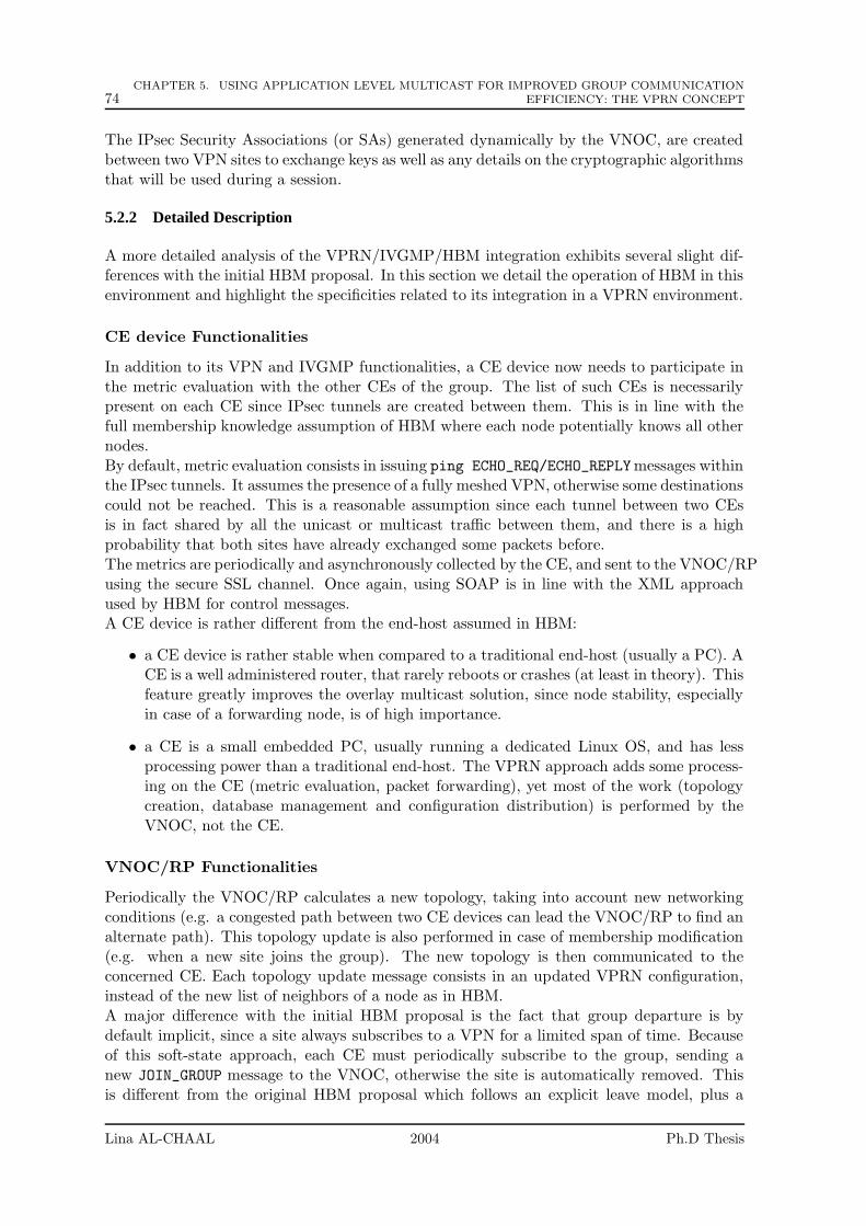
74CHAPTER 5. USING APPLICATION LEVEL MULTICAST FOR IMPROVED GROUP COMMUNICATION
EFFICIENCY: THE VPRN CONCEPT
The IPsec Security Associations (or SAs) generated dynamically by the VNOC, are createdbetween two VPN sites to exchange keys as well as any details on the cryptographic algorithmsthat will be used during a session.
5.2.2 Detailed Description
A more detailed analysis of the VPRN/IVGMP/HBM integration exhibits several slight dif-ferences with the initial HBM proposal. In this section we detail the operation of HBM in thisenvironment and highlight the specificities related to its integration in a VPRN environment.
CE device Functionalities
In addition to its VPN and IVGMP functionalities, a CE device now needs to participate inthe metric evaluation with the other CEs of the group. The list of such CEs is necessarilypresent on each CE since IPsec tunnels are created between them. This is in line with thefull membership knowledge assumption of HBM where each node potentially knows all othernodes.By default, metric evaluation consists in issuing ping ECHO_REQ/ECHO_REPLYmessages withinthe IPsec tunnels. It assumes the presence of a fully meshed VPN, otherwise some destinationscould not be reached. This is a reasonable assumption since each tunnel between two CEsis in fact shared by all the unicast or multicast traffic between them, and there is a highprobability that both sites have already exchanged some packets before.The metrics are periodically and asynchronously collected by the CE, and sent to the VNOC/RPusing the secure SSL channel. Once again, using SOAP is in line with the XML approachused by HBM for control messages.A CE device is rather different from the end-host assumed in HBM:
• a CE device is rather stable when compared to a traditional end-host (usually a PC). ACE is a well administered router, that rarely reboots or crashes (at least in theory). Thisfeature greatly improves the overlay multicast solution, since node stability, especiallyin case of a forwarding node, is of high importance.
• a CE is a small embedded PC, usually running a dedicated Linux OS, and has lessprocessing power than a traditional end-host. The VPRN approach adds some process-ing on the CE (metric evaluation, packet forwarding), yet most of the work (topologycreation, database management and configuration distribution) is performed by theVNOC, not the CE.
VNOC/RP Functionalities
Periodically the VNOC/RP calculates a new topology, taking into account new networkingconditions (e.g. a congested path between two CE devices can lead the VNOC/RP to find analternate path). This topology update is also performed in case of membership modification(e.g. when a new site joins the group). The new topology is then communicated to theconcerned CE. Each topology update message consists in an updated VPRN configuration,instead of the new list of neighbors of a node as in HBM.A major difference with the initial HBM proposal is the fact that group departure is bydefault implicit, since a site always subscribes to a VPN for a limited span of time. Becauseof this soft-state approach, each CE must periodically subscribe to the group, sending anew JOIN_GROUP message to the VNOC, otherwise the site is automatically removed. Thisis different from the original HBM proposal which follows an explicit leave model, plus a
Lina AL-CHAAL 2004 Ph.D Thesis
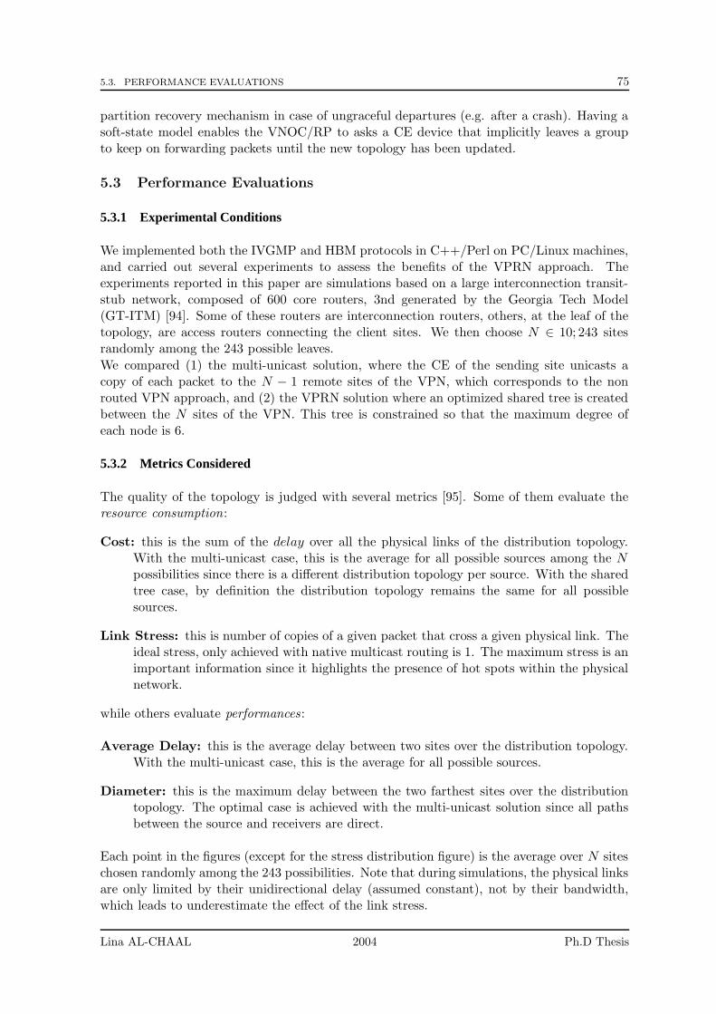
5.3. PERFORMANCE EVALUATIONS 75
partition recovery mechanism in case of ungraceful departures (e.g. after a crash). Having asoft-state model enables the VNOC/RP to asks a CE device that implicitly leaves a groupto keep on forwarding packets until the new topology has been updated.
5.3 Performance Evaluations
5.3.1 Experimental Conditions
We implemented both the IVGMP and HBM protocols in C++/Perl on PC/Linux machines,and carried out several experiments to assess the benefits of the VPRN approach. Theexperiments reported in this paper are simulations based on a large interconnection transit-stub network, composed of 600 core routers, 3nd generated by the Georgia Tech Model(GT-ITM) [94]. Some of these routers are interconnection routers, others, at the leaf of thetopology, are access routers connecting the client sites. We then choose N ∈ 10; 243 sitesrandomly among the 243 possible leaves.
We compared (1) the multi-unicast solution, where the CE of the sending site unicasts acopy of each packet to the N − 1 remote sites of the VPN, which corresponds to the nonrouted VPN approach, and (2) the VPRN solution where an optimized shared tree is createdbetween the N sites of the VPN. This tree is constrained so that the maximum degree ofeach node is 6.
5.3.2 Metrics Considered
The quality of the topology is judged with several metrics [95]. Some of them evaluate theresource consumption:
Cost: this is the sum of the delay over all the physical links of the distribution topology.With the multi-unicast case, this is the average for all possible sources among the N
possibilities since there is a different distribution topology per source. With the sharedtree case, by definition the distribution topology remains the same for all possiblesources.
Link Stress: this is number of copies of a given packet that cross a given physical link. Theideal stress, only achieved with native multicast routing is 1. The maximum stress is animportant information since it highlights the presence of hot spots within the physicalnetwork.
while others evaluate performances:
Average Delay: this is the average delay between two sites over the distribution topology.With the multi-unicast case, this is the average for all possible sources.
Diameter: this is the maximum delay between the two farthest sites over the distributiontopology. The optimal case is achieved with the multi-unicast solution since all pathsbetween the source and receivers are direct.
Each point in the figures (except for the stress distribution figure) is the average over N siteschosen randomly among the 243 possibilities. Note that during simulations, the physical linksare only limited by their unidirectional delay (assumed constant), not by their bandwidth,which leads to underestimate the effect of the link stress.
Lina AL-CHAAL 2004 Ph.D Thesis
76CHAPTER 5. USING APPLICATION LEVEL MULTICAST FOR IMPROVED GROUP COMMUNICATION
EFFICIENCY: THE VPRN CONCEPT
0
10000
20000
30000
40000
50000
60000
70000
80000
50 100 150 200 250
Cos
t(m
s)
Number of Members
Multi-unicast CostTree cost
(a) Cost
0
200
400
600
800
1000
50 100 150 200 250
Del
ay (
ms)
Number of Members
Multi-unicast DelayTree Delay
(b) Average Delay
0
500
1000
1500
2000
2500
50 100 150 200 250
Top
olog
y D
iam
eter
(m
s)
Number of Members
Multi-unicast DiameterTree Diameter
(c) Diameter
0
0.5
1
1.5
2
2.5
3
3.5
4
50 100 150 200 250
Cos
t, D
elay
, and
Dia
met
er R
atio
s
Number of Members
Cost RatioDelay Ratio
Diameter Ratio
(d) shared tree
multi unicastRatios
Figure 5.3. Multi-unicast versus constrained shared tree comparison
5.3.3 Results and Discussion
Figures 5.3 (a)-(d) and 5.4 (a)-(d) compare performance metrics (average delay and diam-eter) and resource consumption metrics (cost and link stress) with the multi-unicast andconstrained shared tree topologies. Figure 5.4 (c) is a zoom that emphasizes the tail distri-bution, but that does not show that most links have a stress at most equal to 5, and 325links a stress equal to 1.
The multi-unicast topology is quickly limited by the fan-out of the sending site (equal toN − 1) which creates a high stress on the first few links. This is visible on figures 5.4-(a)(look at the maximum stress) and (d) (stress distribution, showing a tail distribution atx = N − 1). Consequently, the multi-unicast approach is definitely not a reasonable solutionwhen there are more than a few tens sites (especially as these tests underestimates the effectsof the link stress).
On the opposite the constrained tree, by construction, limits this maximum stress (at most 6neighbors in these experiments), no matter what is the number of sites, N . The price to payis a higher maximum delay/diameter of the topology, but experiments show that the stretchfactor when compared to the unicast case remains inferior to 3.5 which is fairly reasonable.
Note that in case of a single source application, the distribution topology can be optimizedusing a per-source tree. This is made possible by the total control over the topology at theVNOC/RP. The only difficulty is inform the VNOC of this application specific feature.
5.4 Partial Conclusions
In this paper we only considered degree-bounded shared tree overlay topologies. Other overlaytopologies are possible. For instance [82] discusses several algorithms/heuristics to optimizeboth the topology diameter and bandwidth usage at the overlay nodes.
Lina AL-CHAAL 2004 Ph.D Thesis
5.4. PARTIAL CONCLUSIONS 77
0
50
100
150
200
250
50 100 150 200 250
Str
ess
Number of Members
Min/Average/Max Link Stress
(a) Multi-unicast min/aver/max LinkStress
0
1
2
3
4
5
6
7
8
9
50 100 150 200 250
Str
ess
Number of Members
Min/Average/Max link stress
(b) Shared Tree min/aver/max LinkStress
0
1
2
3
4
5
6
7
8
9
0 20 40 60 80 100 120 140 160 180 200
Num
ber
of p
hysi
cal l
inks
Stress
Link Stress Distribution
(c) Multi-unicast link stress distributionwith N = 200 sites (ZOOM)
0
50
100
150
200
250
300
350
400
1 2 3 4 5 6
Num
ber
of p
hysi
cal l
inks
Stress
Link Stress Distribution
(d) Shared tree link stress distributionwith N = 200 sites
Figure 5.4. Multi-unicast versus constrained shared tree link stress comparison.
[75] describes a solution to offer a multicast service over MPLS/BGP VPNs, using PIMwithin the VPN and customer routers at different sites. This solution differs from ours bythe fact (1) it is aimed to be used in the service-provider backbones specified in [15], whileour approach is based on edge technology, and (2) it does not address the problem of usingPIM along with IPsec.
As mentioned before, a PPVPN can easily and efficiently offer a group communication service.[70] describes, at a high level, how the VPN can exploit either a multicast routing service inthe provider’s network, or an MPLS-enabled infrastructure.
Finally, our approach shares some similarities with the Centralized Multicast (CM) approach[51]. In CM, the data forwarding and control functions are kept separated, and the controlpart is centralized in distinct control elements. The control elements are arranged in a two-level hierarchy within autonomous systems and are used to set up multicast trees. In ourapproach too, the control part is centralized in the VNOC. The major difference yet it thatCM does not address security.
In this chapter we show how to build a fully secure and efficient group communication servicebetween several sites. It details both the underlying motivations and the architecture pro-posed. It is a follow-up of work we performed on offering a group communication service inan IPsec IPVPN environment [5] and on the HBM application-level multicast protocol [73].We show that these proposals, that both follow a centralized approach, naturally fit with one-another and lead to the concept of Virtual Private Routed Network, of VPRN. This conceptenables us to largely improve distribution efficiency, in particular by reducing the stress laidon the physical infrastructure, over the multi-unicast approach used so far to distribute pack-ets between the sites. It is worth noting that centralized overlay multicast approaches, oftencriticized, find a perfect field of application in VPN environments, and the security benefitsbrought by the whole architecture largely compensate any possible scalability limitation.
Lina AL-CHAAL 2004 Ph.D Thesis

78CHAPTER 5. USING APPLICATION LEVEL MULTICAST FOR IMPROVED GROUP COMMUNICATION
EFFICIENCY: THE VPRN CONCEPT
Finally IVGMP and HBM have both been implemented and simulations carried out to quan-tify the gains made possible by the VPRN approach.
Lina AL-CHAAL 2004 Ph.D Thesis
Chapter 6
Managing and Securing WebServices with VPNs
Contents
6.1 Background . . . . . . . . . . . . . . . . . . . . . . . . . . . . . . . . 79
6.1.1 Requirements for Standard Technologies in our VPN Approach . . . 80
6.1.2 Web Services Evolution and Challenges . . . . . . . . . . . . . . . . 80
6.2 Our Approach: VPN Web Services Architecture . . . . . . . . . 84
6.2.1 Introduction to the VPN Web Service Architecture . . . . . . . . . . 84
6.2.2 VPN Web Service Phases . . . . . . . . . . . . . . . . . . . . . . . . 85
6.3 Implementation and Evaluation of a VPN Web Service Platform 88
6.4 Partial Conclusions . . . . . . . . . . . . . . . . . . . . . . . . . . . 90
Web Services constitute a set of technologies that many believe will change the web communi-cation landscape within the next few years. They offer standardized and easy communicationsfor distributed systems over the Internet. However their dynamic and distributed nature re-quires a well-managed system, and pending security issues prevent their widespread adoption.Meanwhile there is a big rage toward the use of VPNs to secure communications in a cost-effective environment like the Internet. In this chapter we explain how to merge these twotechnologies in a new powerful hybrid model that: (1) enables an easy management of webservices, (2) provides web services security thanks to the use of dynamic and programmableVPNs, and (3) remains simple and fully integrated. The proposed solution provides an easyand fast way to accomplish a well-manged secure web service over the Internet rather than acomplex sophisticated architecture.
This chapter is organized as follows: in section 6.1 we discuss web services and highlight thepending management and security issues; we detail our proposal in section 13.2 and discusssome design and performance aspects in section 13.3; finally we conclude.
6.1 Background
There is clearly a mutual need between the web service and the VPN technologies. Theproposed model fuses several security technologies, IPsec and SSL, and the web servicestechnology into the same melting pot.
79

80 CHAPTER 6. MANAGING AND SECURING WEB SERVICES WITH VPNS
The resulting hybrid model: (1) enables an easy management of web services, (2) providesweb services security thanks to the use of dynamic and programmable VPNs, and (3) remainssimple and fully integrated.
6.1.1 Requirements for Standard Technologies in our VPN Approach
The control operations between the VNOC and an ED rely on several XML control messagessent over HTTPS. Obviously, the use of a specific XML language between the VNOC and anED creates an interoperability problem, since each ED must know this language to be able totake part in site-to-site VPNs. Therefore the use of the VPN technology for managed a webservice seems to be a good candidate, since it provides a way to access VNOC services in acompletely independent manner using a standard language like SOAP. Creating a VPN webservice will create a way to query, invoke and communicate with the VNOC services withouthaving to care about the VNOC specifications.
6.1.2 Web Services Evolution and Challenges
The WWW is more and more used for application-to-application communications [25]. Webservices are a new breed of web applications. They are self-contained, self-describing, modularapplications that can be published, located and invoked across the Web [59]. Web servicesperform functions which can be anything from simple requests to complex business processes.Once a web service is deployed, other applications (and other web services) can discoverand invoke this service. Actually, a web service is a veneer for access services in othermiddleware platforms. Web services provide a standard means of interoperability betweendifferent applications, running on a variety of platforms and frameworks. One of their strengthis the use of standard web technologies [64] (e.g. XML, SOAP, WSDL, UDDI), as will beexplained latter on.However other issues like the security and dynamic management of web service architecturesare still under discussion. We now introduce web services and focus on the limitations ofcurrent solutions.
Web Service Architecture
A web service architecture is also referred to ”Service Oriented Architecture”, since the serviceis aimed to fulfill a specific client needs [89]. A typical web service consists of three elements:
• a Service Requester (the client), who requests the execution of a web service,
• a Service Discovery Agency, who typically operates as a repository where a serviceprovider publishes its services, and
• a Service Provider (later referred to as a web service platform), who provides a set ofservices.
In a typical scenario, a service provider first describes a web service and publishes it to aservice discovery agency. A service requester retrieves the web service description from servicediscovery agency, and invokes the web service implementation from the service provider. Therole of the service discovery agency becomes more important when a service requester mayask multiple services supplied by different service providers.The use of standard technologies was the main factor of the web service success [65]. Amongthem is the use of the XML language. XML provides a metalanguage in which you can write
Lina AL-CHAAL 2004 Ph.D Thesis
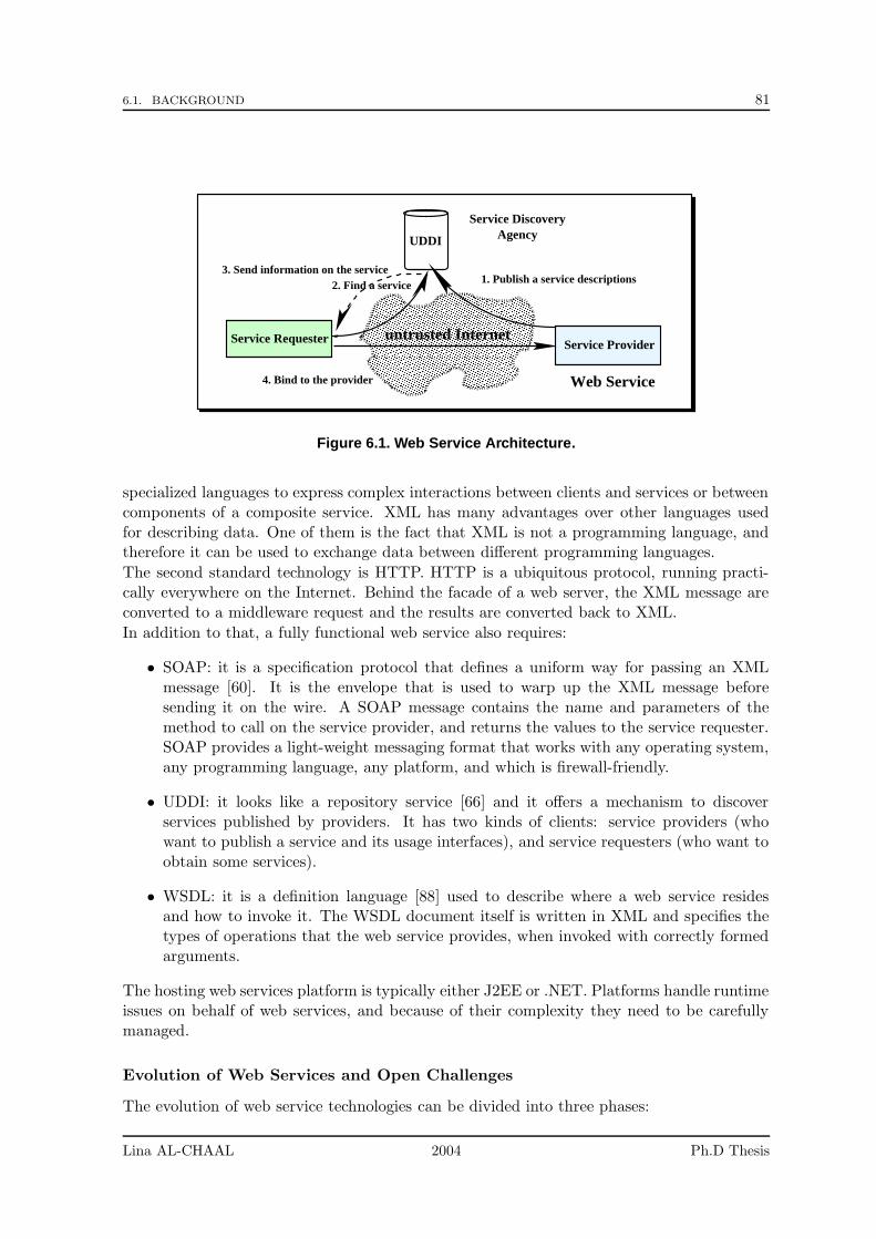
6.1. BACKGROUND 81
��������������������������������������������������������������������������������������������������������������������������������������������������������������������������������������������������������������������������������������������������������������������������������������������������������������������������������������������������������������������������������������������������������������������������������������������������������������������������������������������������������������������������������������������������������������������������������������������������������������������������������������������������������������������������������������������������������������������������������������������������������������������
��������������������������������������������������������������������������������������������������������������������������������������������������������������������������������������������������������������������������������������������������������������������������������������������������������������������������������������������������������������������������������������������������������������������������������������������������������������������������������������������������������������������������������������������������������������������������������������������������������������������������������������������������������������������������������������������������������������������������������������������������������������������
UDDI Agency
Service Requester
1. Publish a service descriptions
untrusted Internet
4. Bind to the provider
2. Find a service3. Send information on the service
Service Discovery
Web Service
Service Provider
Figure 6.1. Web Service Architecture.
specialized languages to express complex interactions between clients and services or betweencomponents of a composite service. XML has many advantages over other languages usedfor describing data. One of them is the fact that XML is not a programming language, andtherefore it can be used to exchange data between different programming languages.
The second standard technology is HTTP. HTTP is a ubiquitous protocol, running practi-cally everywhere on the Internet. Behind the facade of a web server, the XML message areconverted to a middleware request and the results are converted back to XML.
In addition to that, a fully functional web service also requires:
• SOAP: it is a specification protocol that defines a uniform way for passing an XMLmessage [60]. It is the envelope that is used to warp up the XML message beforesending it on the wire. A SOAP message contains the name and parameters of themethod to call on the service provider, and returns the values to the service requester.SOAP provides a light-weight messaging format that works with any operating system,any programming language, any platform, and which is firewall-friendly.
• UDDI: it looks like a repository service [66] and it offers a mechanism to discoverservices published by providers. It has two kinds of clients: service providers (whowant to publish a service and its usage interfaces), and service requesters (who want toobtain some services).
• WSDL: it is a definition language [88] used to describe where a web service residesand how to invoke it. The WSDL document itself is written in XML and specifies thetypes of operations that the web service provides, when invoked with correctly formedarguments.
The hosting web services platform is typically either J2EE or .NET. Platforms handle runtimeissues on behalf of web services, and because of their complexity they need to be carefullymanaged.
Evolution of Web Services and Open Challenges
The evolution of web service technologies can be divided into three phases:
Lina AL-CHAAL 2004 Ph.D Thesis
82 CHAPTER 6. MANAGING AND SECURING WEB SERVICES WITH VPNS
• The first phase concerned the basic standards: XML, SOAP, UDDI and WSDL. Thanksto the efforts of such standardization groups as W3C and WS-I (Web Service Interop-erability Organization), these standards are now rather mature.
• The second phase addresses the security and reliability issues. This phase is still inan intermediary stage, despite the big efforts of several working groups such as OASIS(Organization for the Advancement of Structured Information Standards), WS-I andothers. For instance WS-I is working on critical web services specifications like XMLDigital Signature, XML Encryption, HTTP-R, SAML (Security Assertion Markup Lan-guage), and XACML (eXtensible Access Control Markup Language).
• The third phase addresses the provisioning, monitoring and system management. Thisphase is really in the very early stages of discussion, even if it is of utmost practicalimportance.
Since the functional requirements are essentially covered, challenges have moved to the man-agement and security aspects.
Management Challenges:
A successful approach to web service management requires a set of flexible, inter-operablesecurity primitives that, through policy and configuration, enable a variety of secure solutions,in addition to a set of policies for deploying, operating and monitoring web services. In thiswork we concentrate on the external management operations (i.e. the management operationsbetween a web service platform and the client environments) rather than on the internal ones.External management operations include:
• client identification: clients are given a unique identity when placed under manage-ment control. Without these identities, monitoring all instances of the web serviceenvironment would be complex.
• client authentication and authorization: the goal is to authenticate clients and givethem the right or not to invoke services from a web service platform.
• monitoring operations: the goal can be to determine whether a web service instance isworking correctly, to get the list of clients currently hosted on the web service platform,the list of web service instances currently responding or not, or the average dispatchtime for messages sent between web service instances.
• configuration deployment: configuration policies must be deployed in order to securecommunications between a client and a web service platform. By having enough in-formation about clients, generating suitable configuration policies that conform to theclients environments is much easier.
Yet the current web services standards do not handle all above issues. A significant limitationis the management of authorization and security events, as well as the explicit capabilities ofmonitoring, configuring and identifying.
Security Challenges:
Most of the current efforts concern security issues. Many languages are created for thispurpose (but are not yet finished). One of these languages, known as Web Services SecurityLanguage (WS-Security), defines SOAP extensions that can be used to provide integrity andconfidentiality [47]. Other languages use XML extensions for these purposes:
Lina AL-CHAAL 2004 Ph.D Thesis
6.1. BACKGROUND 83
• XML Signature [39] describes how to digitally sign an XML document and providesintegrity, signature assurance, and non-repudiation for web data.
• XML Encryption [40] describes how to encrypt an XML document and represents theencrypted content of XML data and the information that enables a recipient to decryptit.
• XML Key Management Specification (XKMS) [41] describes an XML-based protocolfor delegated trust and specifies protocols for distributing and registering public keys(used in conjunction with XML Signature).
• XACML [68] provides a specification for policies to access XML documents, based onobjects (elements to be accessed in the XML document), subject (the user), action(read, write, create, delete)
• SAML [67] describes authentication, attributes, and authorization decision
• Service Provisioning Markup Language (SPML) [69] uses for exchanging user, resource,and service provisioning information
These standards do not address the larger problem of how to secure a web service, but howto secure XML data, no matter whether it is part of a web service or not. Moreover they donot address the issue of transport protocol security, although transport is an integral pieceof end-to-end secure messaging required.Other technologies are used for establishing secure connections over HTTP like SSL and TLS[28]. Basically transport security for web service messaging consists in using SOAP overHTTP/SSL or TLS.Using IPsec is another way to secure web service messages. It provides peer authentication,confidentiality and integrity of IP packets. However fundamental differences exist betweenSSL/TLS and IPsec as explained in section 11.2.1.No matter whether the security technology is for point-to-point or end-to-end communica-tions, a high level of security management is required to prevent conflicts between web serviceinstances and to deploy security policies without any interoperability problem. Additionally,these policies should be generated in a dynamic way, without any human intervention, eachtime a client requests a web service.
Related Works in Security and Management Services
Security remains an important barrier to customer adoption of web services, and in spiteof many efforts, no single standard for security exists. Many documents and drafts havebeen written in this domain, yet the vast majority remains highly theoretical, as opposed topractical, real-world implementations.The WS-Security document, which is now developed in the OASIS standards body, shouldbe published for public comments and is expected to be completed within a few months. TheWS-I (Web Services Interoperability) organization was formed recently and to promote openstandards for web services interoperability across platforms, applications, and programminglanguages, and it will come up with security specifications, in particular WS-Security. Yetmost standards require some time before they are truly useful from an interoperability pointof view, and web services security standards are no exception.As for management issues, no serious efforts have been done, and most of them are propri-etary approaches from major application developers and providers. Lately a new OASIS WebServices Distributed Management (WSDM) Technical Committee was created as a way to
Lina AL-CHAAL 2004 Ph.D Thesis
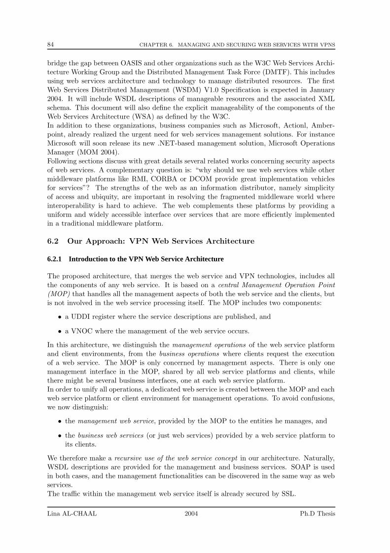
84 CHAPTER 6. MANAGING AND SECURING WEB SERVICES WITH VPNS
bridge the gap between OASIS and other organizations such as the W3C Web Services Archi-tecture Working Group and the Distributed Management Task Force (DMTF). This includesusing web services architecture and technology to manage distributed resources. The firstWeb Services Distributed Management (WSDM) V1.0 Specification is expected in January2004. It will include WSDL descriptions of manageable resources and the associated XMLschema. This document will also define the explicit manageability of the components of theWeb Services Architecture (WSA) as defined by the W3C.In addition to these organizations, business companies such as Microsoft, Actionl, Amber-point, already realized the urgent need for web services management solutions. For instanceMicrosoft will soon release its new .NET-based management solution, Microsoft OperationsManager (MOM 2004).Following sections discuss with great details several related works concerning security aspectsof web services. A complementary question is: “why should we use web services while othermiddleware platforms like RMI, CORBA or DCOM provide great implementation vehiclesfor services”? The strengths of the web as an information distributor, namely simplicityof access and ubiquity, are important in resolving the fragmented middleware world whereinteroperability is hard to achieve. The web complements these platforms by providing auniform and widely accessible interface over services that are more efficiently implementedin a traditional middleware platform.
6.2 Our Approach: VPN Web Services Architecture
6.2.1 Introduction to the VPN Web Service Architecture
The proposed architecture, that merges the web service and VPN technologies, includes allthe components of any web service. It is based on a central Management Operation Point(MOP) that handles all the management aspects of both the web service and the clients, butis not involved in the web service processing itself. The MOP includes two components:
• a UDDI register where the service descriptions are published, and
• a VNOC where the management of the web service occurs.
In this architecture, we distinguish the management operations of the web service platformand client environments, from the business operations where clients request the executionof a web service. The MOP is only concerned by management aspects. There is only onemanagement interface in the MOP, shared by all web service platforms and clients, whilethere might be several business interfaces, one at each web service platform.In order to unify all operations, a dedicated web service is created between the MOP and eachweb service platform or client environment for management operations. To avoid confusions,we now distinguish:
• the management web service, provided by the MOP to the entities he manages, and
• the business web services (or just web services) provided by a web service platform toits clients.
We therefore make a recursive use of the web service concept in our architecture. Naturally,WSDL descriptions are provided for the management and business services. SOAP is usedin both cases, and the management functionalities can be discovered in the same way as webservices.The traffic within the management web service itself is already secured by SSL.
Lina AL-CHAAL 2004 Ph.D Thesis
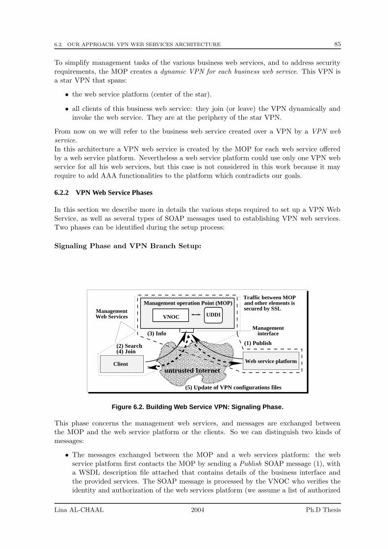
6.2. OUR APPROACH: VPN WEB SERVICES ARCHITECTURE 85
To simplify management tasks of the various business web services, and to address securityrequirements, the MOP creates a dynamic VPN for each business web service. This VPN isa star VPN that spans:
• the web service platform (center of the star).
• all clients of this business web service: they join (or leave) the VPN dynamically andinvoke the web service. They are at the periphery of the star VPN.
From now on we will refer to the business web service created over a VPN by a VPN webservice.In this architecture a VPN web service is created by the MOP for each web service offeredby a web service platform. Nevertheless a web service platform could use only one VPN webservice for all his web services, but this case is not considered in this work because it mayrequire to add AAA functionalities to the platform which contradicts our goals.
6.2.2 VPN Web Service Phases
In this section we describe more in details the various steps required to set up a VPN WebService, as well as several types of SOAP messages used to establishing VPN web services.Two phases can be identified during the setup process:
Signaling Phase and VPN Branch Setup:
���������������������������������������������������������������������������������������������������������������������������������������������������������������������������������������������������������������������������������������������������������������������������������������������������������������������������������������������������������������������������������������������������������������������������������������������������������������������������������������������������������������������������������������������������������������������������������������������������������������������������������������������������������������������������������������������������������������������������������������������������������������������������������������������������������
���������������������������������������������������������������������������������������������������������������������������������������������������������������������������������������������������������������������������������������������������������������������������������������������������������������������������������������������������������������������������������������������������������������������������������������������������������������������������������������������������������������������������������������������������������������������������������������������������������������������������������������������������������������������������������������������������������������������������������������������������������������������������������������������������������
Managementinterface
UDDIManagementWeb Services
Traffic between MOPand other elements issecured by SSL
untrusted InternetWeb service platformClient
Management operation Point (MOP)
VNOC
(2) Search (1) Publish
(3) Info
(4) Join
(5) Update of VPN configurations files
Figure 6.2. Building Web Service VPN: Signaling Phase.
This phase concerns the management web services, and messages are exchanged betweenthe MOP and the web service platform or the clients. So we can distinguish two kinds ofmessages:
• The messages exchanged between the MOP and a web services platform: the webservice platform first contacts the MOP by sending a Publish SOAP message (1), witha WSDL description file attached that contains details of the business interface andthe provided services. The SOAP message is processed by the VNOC who verifies theidentity and authorization of the web services platform (we assume a list of authorized
Lina AL-CHAAL 2004 Ph.D Thesis
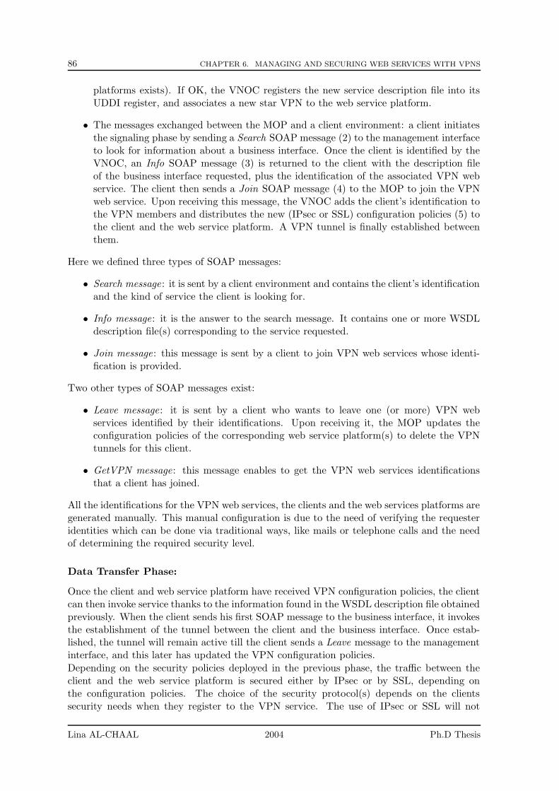
86 CHAPTER 6. MANAGING AND SECURING WEB SERVICES WITH VPNS
platforms exists). If OK, the VNOC registers the new service description file into itsUDDI register, and associates a new star VPN to the web service platform.
• The messages exchanged between the MOP and a client environment: a client initiatesthe signaling phase by sending a Search SOAP message (2) to the management interfaceto look for information about a business interface. Once the client is identified by theVNOC, an Info SOAP message (3) is returned to the client with the description fileof the business interface requested, plus the identification of the associated VPN webservice. The client then sends a Join SOAP message (4) to the MOP to join the VPNweb service. Upon receiving this message, the VNOC adds the client’s identification tothe VPN members and distributes the new (IPsec or SSL) configuration policies (5) tothe client and the web service platform. A VPN tunnel is finally established betweenthem.
Here we defined three types of SOAP messages:
• Search message: it is sent by a client environment and contains the client’s identificationand the kind of service the client is looking for.
• Info message: it is the answer to the search message. It contains one or more WSDLdescription file(s) corresponding to the service requested.
• Join message: this message is sent by a client to join VPN web services whose identi-fication is provided.
Two other types of SOAP messages exist:
• Leave message: it is sent by a client who wants to leave one (or more) VPN webservices identified by their identifications. Upon receiving it, the MOP updates theconfiguration policies of the corresponding web service platform(s) to delete the VPNtunnels for this client.
• GetVPN message: this message enables to get the VPN web services identificationsthat a client has joined.
All the identifications for the VPN web services, the clients and the web services platforms aregenerated manually. This manual configuration is due to the need of verifying the requesteridentities which can be done via traditional ways, like mails or telephone calls and the needof determining the required security level.
Data Transfer Phase:
Once the client and web service platform have received VPN configuration policies, the clientcan then invoke service thanks to the information found in the WSDL description file obtainedpreviously. When the client sends his first SOAP message to the business interface, it invokesthe establishment of the tunnel between the client and the business interface. Once estab-lished, the tunnel will remain active till the client sends a Leave message to the managementinterface, and this later has updated the VPN configuration policies.
Depending on the security policies deployed in the previous phase, the traffic between theclient and the web service platform is secured either by IPsec or by SSL, depending onthe configuration policies. The choice of the security protocol(s) depends on the clientssecurity needs when they register to the VPN service. The use of IPsec or SSL will not
Lina AL-CHAAL 2004 Ph.D Thesis
6.2. OUR APPROACH: VPN WEB SERVICES ARCHITECTURE 87
��������������������������������������������������������������������������������������������������������������������������������������������������������������������������������������������������������������������������������������������������������������������������������������������������������������������������������������������������������������������������������������������������������������������������������������������������������������������������������������������������������������������������������������������������������������������������������������������������������������������������������������������������������������������������������������������������������������������������������������������������������������������
����������������������������������������������������������������������������������������������������������������������������������������������������������������������������������������������������������������������������������������������������������������������������������������������������������������������������������������������������������������������������������������������������������������������������������������������������������������������������������������������������������������������������������������������������������������������������������������������������������������������������������������������������������������������������������������������������������������������������Secure tunnel
of the VPN Web Service
UDDI
web service platform, is securedby VPN tunnel
Traffic between a client and a
untrusted Internet
Management operation Point (MOP)
VNOC
Web Service Platform
Business Interface
Client
Figure 6.3. Building Web Service VPN: Data Transfer Phase.
prevent the use of other technologies such as XML signature or SAML to secure point-to-point communications, but they add another level of security.
Another benefit is that a VPN web service contains only authorized members who are inter-ested in invoking its services. Thus a web service platform does not care about the authen-tication and access control of clients any more. These security aspects are performed by theVNOC on behalf of the web services platforms.
Example
Here is a small scenario of how this could function in whole:
First of all, a web service platform gets its identification from the management point as wellas a VPN’s identification of the star VPN that is centered around the web service platform.When a web service platform is ready to publish its services to the UDDI of the managementpoint, it sends a Publish message that includes a WSDL description file and its identification.The VNOC arranges the WSDL into the UDDI register, after receiving the message via themanagement interface.
After publishing services description files, a client could get a file description from the man-agement point. Again the client should get its own identification to be able to contact themanagement interface. Once the client gets its identification, it could send aSearch messageasking for a special service. The VNOC sends back an Info message including WSDL descrip-tion files according to the service requested by the client and the VPN identifications of thecorresponding services. The client now is freely to ask to join a VPN web service. As soonas the management point gets a Join message from the client, it sends back configurationpolicies to establish VPN tunnel between the client and the matching web service platform.
Now the VPN web service contains the web service platform and that client. Platform’sservices could be invoked by simple Invoke messages issuing by the client. The messages be-tween the web service platform and the client are completely exchanged via the secure tunnel.Moreover, since the client has been already authenticated by the management point duringthe previous phases, the web service platform does no more care of the client identificationhassles. Sure this does not prevent the use of another security point-to-point level.
Lina AL-CHAAL 2004 Ph.D Thesis
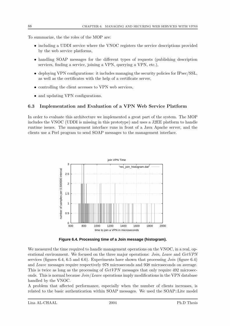
88 CHAPTER 6. MANAGING AND SECURING WEB SERVICES WITH VPNS
To summarize, the the roles of the MOP are:
• including a UDDI service where the VNOC registers the service descriptions providedby the web service platforms,
• handling SOAP messages for the different types of requests (publishing descriptionservices, finding a service, joining a VPN, querying a VPN, etc.),
• deploying VPN configurations: it includes managing the security policies for IPsec/SSL,as well as the certificates with the help of a certificate server,
• controlling the client accesses to VPN web services,
• and updating VPN configurations.
6.3 Implementation and Evaluation of a VPN Web Service Platform
In order to evaluate this architecture we implemented a great part of the system. The MOPincludes the VNOC (UDDI is missing in this prototype) and uses a J2EE platform to handleruntime issues. The management interface runs in front of a Java Apache server, and theclients use a Perl program to send SOAP messages to the management interface.
0
0.5
1
1.5
2
2.5
3
600 800 1000 1200 1400 1600 1800 2000
num
ber
of s
ampl
es p
er 0
.500
000
inte
rval
time to join a VPN in microseconds
join VPN Time
"res_join_histogram.dat"
Figure 6.4. Processing time of a Join message (histogram).
We measured the time required to handle management operations on the VNOC, in a real, op-erational environment. We focused on the three major operations: Join, Leave and GetVPNservices (figures 6.4, 6.5 and 6.6). Experiments have shown that processing Join (figure 6.4)and Leave messages require respectively 978 microseconds and 938 microseconds on average.This is twice as long as the processing of GetVPN messages that only require 492 microsec-onds. This is normal because Join/Leave operations imply modifications in the VPN databasehandled by the VNOC.A problem that affected performance, especially when the number of clients increases, isrelated to the basic authentication within SOAP messages. We used the SOAP::Lite model
Lina AL-CHAAL 2004 Ph.D Thesis
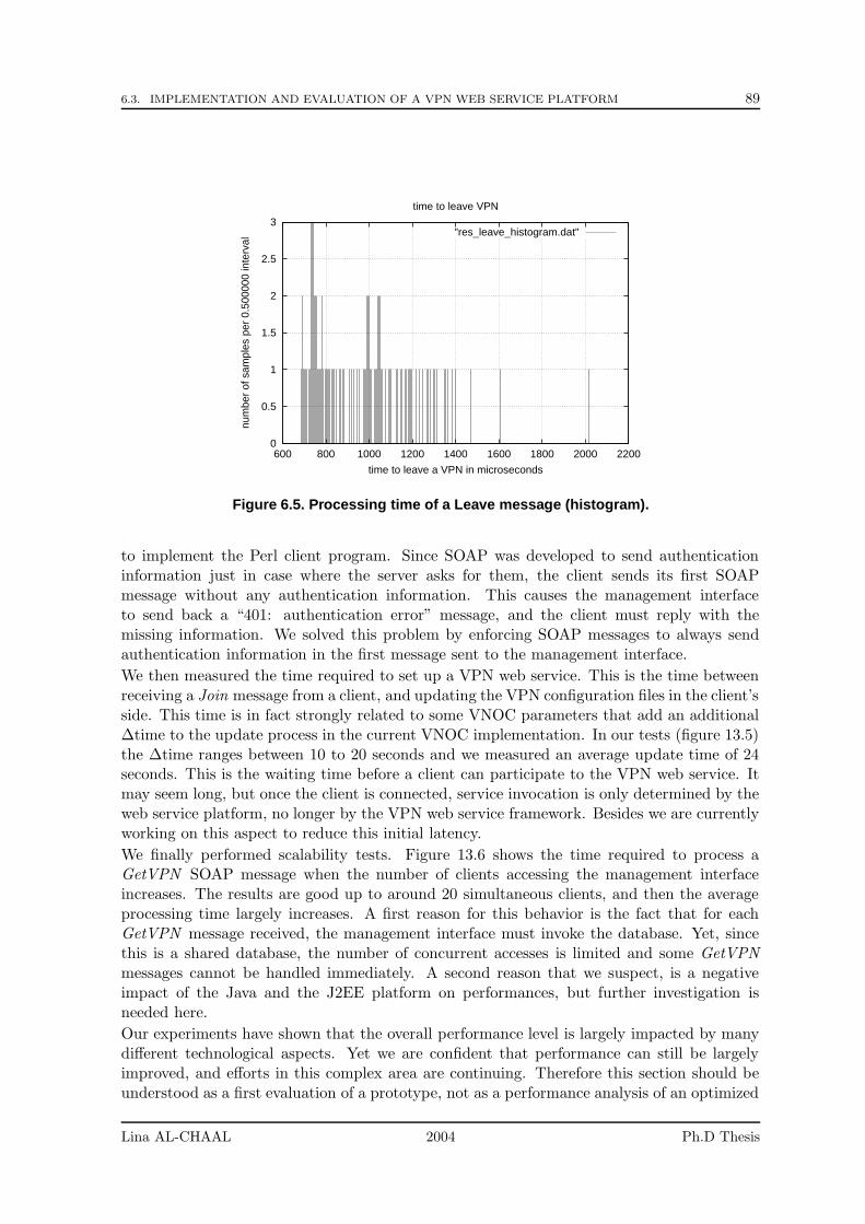
6.3. IMPLEMENTATION AND EVALUATION OF A VPN WEB SERVICE PLATFORM 89
0
0.5
1
1.5
2
2.5
3
600 800 1000 1200 1400 1600 1800 2000 2200
num
ber
of s
ampl
es p
er 0
.500
000
inte
rval
time to leave a VPN in microseconds
time to leave VPN
"res_leave_histogram.dat"
Figure 6.5. Processing time of a Leave message (histogram).
to implement the Perl client program. Since SOAP was developed to send authenticationinformation just in case where the server asks for them, the client sends its first SOAPmessage without any authentication information. This causes the management interfaceto send back a “401: authentication error” message, and the client must reply with themissing information. We solved this problem by enforcing SOAP messages to always sendauthentication information in the first message sent to the management interface.
We then measured the time required to set up a VPN web service. This is the time betweenreceiving a Join message from a client, and updating the VPN configuration files in the client’sside. This time is in fact strongly related to some VNOC parameters that add an additional∆time to the update process in the current VNOC implementation. In our tests (figure 13.5)the ∆time ranges between 10 to 20 seconds and we measured an average update time of 24seconds. This is the waiting time before a client can participate to the VPN web service. Itmay seem long, but once the client is connected, service invocation is only determined by theweb service platform, no longer by the VPN web service framework. Besides we are currentlyworking on this aspect to reduce this initial latency.
We finally performed scalability tests. Figure 13.6 shows the time required to process aGetVPN SOAP message when the number of clients accessing the management interfaceincreases. The results are good up to around 20 simultaneous clients, and then the averageprocessing time largely increases. A first reason for this behavior is the fact that for eachGetVPN message received, the management interface must invoke the database. Yet, sincethis is a shared database, the number of concurrent accesses is limited and some GetVPNmessages cannot be handled immediately. A second reason that we suspect, is a negativeimpact of the Java and the J2EE platform on performances, but further investigation isneeded here.
Our experiments have shown that the overall performance level is largely impacted by manydifferent technological aspects. Yet we are confident that performance can still be largelyimproved, and efforts in this complex area are continuing. Therefore this section should beunderstood as a first evaluation of a prototype, not as a performance analysis of an optimized
Lina AL-CHAAL 2004 Ph.D Thesis
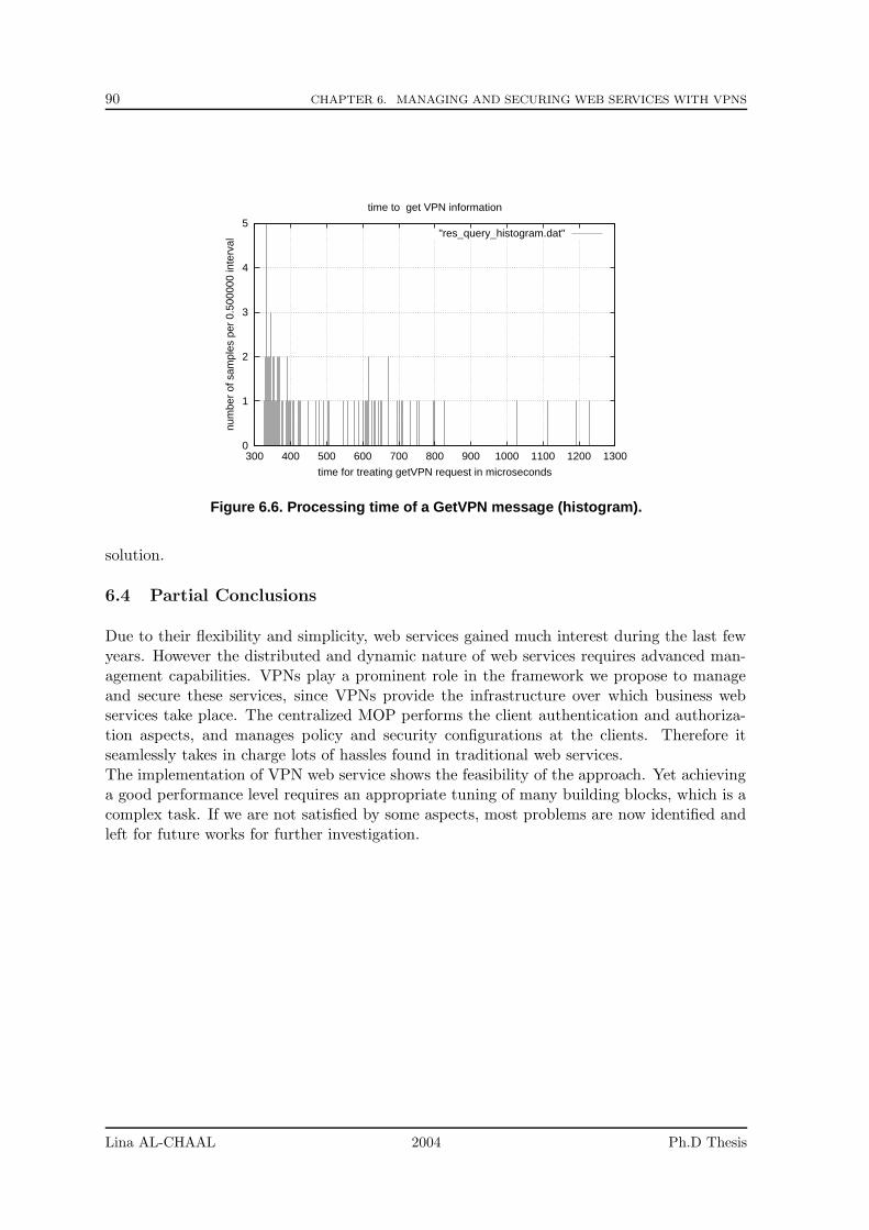
90 CHAPTER 6. MANAGING AND SECURING WEB SERVICES WITH VPNS
0
1
2
3
4
5
300 400 500 600 700 800 900 1000 1100 1200 1300
num
ber
of s
ampl
es p
er 0
.500
000
inte
rval
time for treating getVPN request in microseconds
time to get VPN information
"res_query_histogram.dat"
Figure 6.6. Processing time of a GetVPN message (histogram).
solution.
6.4 Partial Conclusions
Due to their flexibility and simplicity, web services gained much interest during the last fewyears. However the distributed and dynamic nature of web services requires advanced man-agement capabilities. VPNs play a prominent role in the framework we propose to manageand secure these services, since VPNs provide the infrastructure over which business webservices take place. The centralized MOP performs the client authentication and authoriza-tion aspects, and manages policy and security configurations at the clients. Therefore itseamlessly takes in charge lots of hassles found in traditional web services.The implementation of VPN web service shows the feasibility of the approach. Yet achievinga good performance level requires an appropriate tuning of many building blocks, which is acomplex task. If we are not satisfied by some aspects, most problems are now identified andleft for future works for further investigation.
Lina AL-CHAAL 2004 Ph.D Thesis
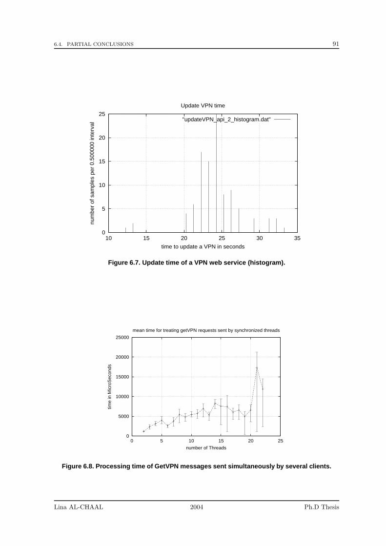
6.4. PARTIAL CONCLUSIONS 91
0
5
10
15
20
25
10 15 20 25 30 35
num
ber
of s
ampl
es p
er 0
.500
000
inte
rval
time to update a VPN in seconds
Update VPN time
"updateVPN_api_2_histogram.dat"
Figure 6.7. Update time of a VPN web service (histogram).
0
5000
10000
15000
20000
25000
0 5 10 15 20 25
time
in M
icro
Sec
onds
number of Threads
mean time for treating getVPN requests sent by synchronized threads
Figure 6.8. Processing time of GetVPN messages sent simultaneously by several clients.
Lina AL-CHAAL 2004 Ph.D Thesis

92 CHAPTER 6. MANAGING AND SECURING WEB SERVICES WITH VPNS
Lina AL-CHAAL 2004 Ph.D Thesis
Chapter 7
Adding Load Balancing for HigherAvailability/Performance
Contents
7.1 Background . . . . . . . . . . . . . . . . . . . . . . . . . . . . . . . . 93
7.2 Definitions . . . . . . . . . . . . . . . . . . . . . . . . . . . . . . . . . 94
7.3 Our First Approach: Load Balancing and High Availability Ar-chitecture . . . . . . . . . . . . . . . . . . . . . . . . . . . . . . . . . 95
7.3.1 Agent Routing Tables . . . . . . . . . . . . . . . . . . . . . . . . . . 97
7.3.2 Scenario . . . . . . . . . . . . . . . . . . . . . . . . . . . . . . . . . . 97
7.3.3 Implementation Aspects . . . . . . . . . . . . . . . . . . . . . . . . . 99
7.4 Redundancy versus Memory Overhead . . . . . . . . . . . . . . . 99
7.5 Our Second Approach: Load Balancing and High PerformanceArchitecture . . . . . . . . . . . . . . . . . . . . . . . . . . . . . . . 101
7.5.1 Hubs or Switches . . . . . . . . . . . . . . . . . . . . . . . . . . . . . 101
7.5.2 Router Example to Better Understand . . . . . . . . . . . . . . . . . 101
7.5.3 VPN Gateway Cluster . . . . . . . . . . . . . . . . . . . . . . . . . . 103
7.6 Partial Conclusions . . . . . . . . . . . . . . . . . . . . . . . . . . . 105
Since our VPN approach is categorized under the CE-based VPNs, the CE devices are theonly vulnerable elements in this model and requirements for configuration managements areunique for CE devices. There are two important points to take into consideration whenmanaging such model: Firstly, it is highly desirable to detect CE device failures rapidly andto enable that the site experiencing the failure continues to operate smoothly.Secondly, whenthe number of communications increases for a given VPN site, it becomes a necessity to finda suitable solution to low the charge on the CE device attached to that VPN site.In this chapter, we show two possible approaches to achieve both a high level of availabilityand performance, and load balancing with our CE-based model.
7.1 Background
Many mechanisms reply to the demand for high availability in VPN environments. Thesemechanisms are based on dynamic routing protocols to detect a case of failure among VPN
93
94CHAPTER 7. ADDING LOAD BALANCING TO OUR VPN APPROACH FOR HIGHER AVAILABILITY OR
HIGHER PERFORMANCE
routers. It is worth mentioning that the main goal behind developing such protocols was todetect VPN routers failure that might occur in the ISP core networks and react rapidly toinsure the best delivery service for clients.
With a dynamic routing mechanism routers must communicate using a routing protocol.The routing daemon, on each router, adds and deletes information into the routing tables asroutes change over time. It also adds routing policies choosing which routes to insert into thekernel’s routing table. In case of multiple routes to the same destination, the daemon chooseswhich route is the best. In the other side, if a link has gone down, the daemon deletes routesconnected to that link, and finds alternatives if they exist.
Dynamic routing protocols are categorized as Interior Gateway Protocols (IGPs) and ExteriorGateway Protocols (EGPs). IGPs are used within an autonomous system, in other words,within a single controlling entity, whereas EGPs are used between autonomous systems. Forinstance, Open Shortest Path First (OSPF) is an IGP that collects and advertises informationabout its neighboring routers. OSPF uses multicasting to reduce the load on systems notparticipating in OSPF routing. In a VPN environment, OSPF uses GRE tunnels to simulatethe private lines over the Internet, and then secures the GRE tunnels using IPSec (probablytransport mode). IPsec could not be used immediately to tunnel OSPF, because routerinterfaces at tunnel endpoints will, in general, not belong to the same subnet, so OSPF willnot work. Moreover IPsec could not tunnel multicast traffic as we discussed before in section4.
The Dynamic Multipoint VPN (DMVPN) proposal is a new IGP developed by Cisco. Itallows users to better scale large and small IPSec VPNs by combining GRE tunnels, IPSecencryption, and Next Hop Resolution Protocol (NHRP).
The Border Gateway Protocol (BGP) is an EGP. BGP is commonly used within and betweenISPs. It enables groups of routers to share routing information so that efficient routes can beestablished.
The Hot Standby Router Protocol (HSRP), is a Cisco protocol that is designed to be usedover multi-access, multicast or broadcast capable LANs (e.g., Ethernet). In particular, theprotocol protects against the failure of the first hop router when the source host cannot learnthe IP address of the first hop router dynamically.
The first approach that we are going to discuss in section 7.3 differs radically from the mech-anisms discussed above since it is based on the dynamic nature of our VPN approach. Thebenefit we get of our approach is that is easy to implement, uses minimal network overheadand consumes minimal memory resources compared to the other protocols mentioned above.On the opposite, the second approach is quite similar in its architecture to these mechanisms.
7.2 Definitions
Before discussing our approaches, we start by introducing the basic terms and concepts usedin the proposed architectures and then provide overviews of the two architectures.
Cluster Concept
A cluster consists of one or more nodes, co-operating to provide certain services by hostingsome resources on one of the cluster nodes. The most common cluster resource is an IPaddress, often combined with an application resource (e.g. database, web server). A useraccesses a cluster service as if it was provided by one single node, and has no way of knowingwhich of the nodes in the cluster is currently hosting the service.
Lina AL-CHAAL 2004 Ph.D Thesis
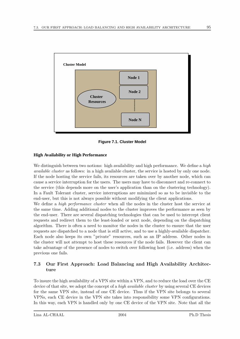
7.3. OUR FIRST APPROACH: LOAD BALANCING AND HIGH AVAILABILITY ARCHITECTURE 95
Cluster Model
Node 1
Node N
Node 2
ResourcesCluster
Figure 7.1. Cluster Model
High Availability or High Performance
We distinguish between two notions: high availability and high performance. We define a highavailable cluster as follows: in a high available cluster, the service is hosted by only one node.If the node hosting the service fails, its resources are taken over by another node, which cancause a service interruption for the users. The users may have to disconnect and re-connect tothe service (this depends more on the user’s application than on the clustering technology).In a Fault Tolerant cluster, service interruptions are minimized so as to be invisible to theend-user, but this is not always possible without modifying the client applications.We define a high performance cluster when all the nodes in the cluster host the service atthe same time. Adding additional nodes to the cluster improves the performance as seen bythe end-user. There are several dispatching technologies that can be used to intercept clientrequests and redirect them to the least-loaded or next node, depending on the dispatchingalgorithm. There is often a need to monitor the nodes in the cluster to ensure that the userrequests are dispatched to a node that is still active, and to use a highly-available dispatcher.Each node also keeps its own ”private” resources, such as an IP address. Other nodes inthe cluster will not attempt to host these resources if the node fails. However the client cantake advantage of the presence of nodes to switch over following host (i.e. address) when theprevious one fails.
7.3 Our First Approach: Load Balancing and High Availability Architec-ture
To insure the high availability of a VPN site within a VPN, and to reduce the load over the CEdevice of that site, we adopt the concept of a high available cluster by using several CE devicesfor the same VPN site, instead of one CE device. Thus if the VPN site belongs to severalVPNs, each CE device in the VPN site takes into responsibility some VPN configurations.In this way, each VPN is handled only by one CE device of the VPN site. Note that all the
Lina AL-CHAAL 2004 Ph.D Thesis
96CHAPTER 7. ADDING LOAD BALANCING TO OUR VPN APPROACH FOR HIGHER AVAILABILITY OR
HIGHER PERFORMANCE
tunnels of a given VPN are necessarily handled by the same CE device of a site. This featureis insured by the VNOC which has a global overview of all VPN sites and the VPNs to whichthey belong.
For each VPN site, we suppose the presence of a VPN agent located behind several CEdevices in the same VPN site. This agent has several functionalities:
• It observes and monitors the CE devices of the VPN site where the agent is located.
• It takes in charge the communications with the VNOC on behalf of the CE devices.
• It sends corrective actions to the VNOC.
As soon as the agent detects that there is a CE device goes down in the local VPN site,it chooses another CE device which works good, and transfers all jobs from the inoperativeCE to the second one. This procedure necessities a kind of interaction with the VNOC, inaddition to new actions that we developed for this purpose with the help of the web service,here are some of them
• DisableSite: this action is used to take off a CE device from a set of VPNs to which itbelongs.
• EnableSite: this action is the reverse action of the previous one. It is used to set a CEdevice as active.
• JoinVPNasBackup: the agent sends this type of request to the VNOC with at least twoparameters; the inoperative CE device and the other CE device that the agent chose toreplace the first one. When the VNOC gets the request, it joins the active CE deviceto all VPNs where the inoperative CE device belongs. But at same time, the VNOCindicates by flag that the new CE device is just joining those VPNs as a backup. Inthat way, once the inoperative device comes back alive, it gets back its jobs.
• SwitchSite: this action is used to switch the role between two CE devices. Thus VPNjobs will be transferred from one CE device to the other. In other way, the VNOC willupdate VPN configurations files on both devices.
• GetSiteBackup: it is used to get information about the backup devices for a specificCE device.
The agent uses a set of the previous actions to ask the VNOC to transfer the jobs from theinoperative CE to another CE device that works correctly. The VNOC treats the agent’srequests and updates information of all VPNs to which the inoperative CE belongs. TheVNOC starts by updating its own database then sending new VPN configurations to alldamaged CE devices to insure perfect VPN functionalities with the VPN site where thefailure occurred. Actually while transferring VPN functionalities from the inoperative CEdevice to the active one, the VNOC sets a flag to indicate that the active CE device is justa backup till the inoperative device gets back working again.
Once the agent detects that the inoperative device gets back working, the previous procedureis repeated. The VNOC gets back all VPN functionalities from the backup device to thatdevice and updates VPN configurations on other VPN sites.
Lina AL-CHAAL 2004 Ph.D Thesis
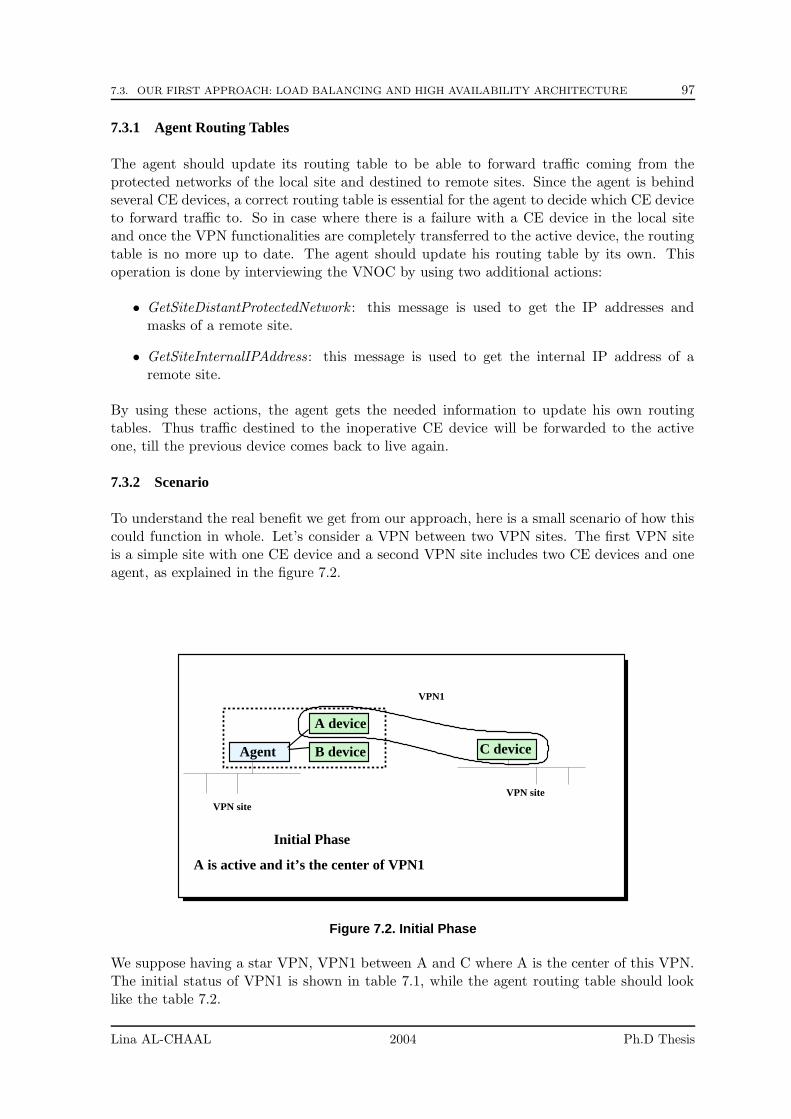
7.3. OUR FIRST APPROACH: LOAD BALANCING AND HIGH AVAILABILITY ARCHITECTURE 97
7.3.1 Agent Routing Tables
The agent should update its routing table to be able to forward traffic coming from theprotected networks of the local site and destined to remote sites. Since the agent is behindseveral CE devices, a correct routing table is essential for the agent to decide which CE deviceto forward traffic to. So in case where there is a failure with a CE device in the local siteand once the VPN functionalities are completely transferred to the active device, the routingtable is no more up to date. The agent should update his routing table by its own. Thisoperation is done by interviewing the VNOC by using two additional actions:
• GetSiteDistantProtectedNetwork : this message is used to get the IP addresses andmasks of a remote site.
• GetSiteInternalIPAddress: this message is used to get the internal IP address of aremote site.
By using these actions, the agent gets the needed information to update his own routingtables. Thus traffic destined to the inoperative CE device will be forwarded to the activeone, till the previous device comes back to live again.
7.3.2 Scenario
To understand the real benefit we get from our approach, here is a small scenario of how thiscould function in whole. Let’s consider a VPN between two VPN sites. The first VPN siteis a simple site with one CE device and a second VPN site includes two CE devices and oneagent, as explained in the figure 7.2.
Initial Phase
A is active and it’s the center of VPN1
VPN siteVPN site
A device
B device C deviceAgent
VPN1
Figure 7.2. Initial Phase
We suppose having a star VPN, VPN1 between A and C where A is the center of this VPN.The initial status of VPN1 is shown in table 7.1, while the agent routing table should looklike the table 7.2.
Lina AL-CHAAL 2004 Ph.D Thesis
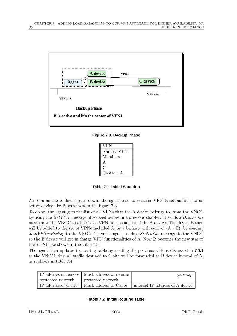
98CHAPTER 7. ADDING LOAD BALANCING TO OUR VPN APPROACH FOR HIGHER AVAILABILITY OR
HIGHER PERFORMANCE
Backup Phase
B is active and it’s the center of VPN1
VPN siteVPN site
A device
B device C deviceAgent
VPN1
Figure 7.3. Backup Phase
VPN
Name : VPN1Members :ACCenter : A
Table 7.1. Initial Situation
As soon as the A device goes down, the agent tries to transfer VPN functionalities to anactive device like B, as shown in the figure 7.3.
To do so, the agent gets the list of all VPNs that the A device belongs to, from the VNOCby using the GetVPN message, discussed before in a previous chapter. It sends a DisableSitemessage to the VNOC to disactivate VPN functionalities of the A device. The device B thenwill be added to the set of VPNs included A, as a backup with symbol (A - B), by sendingJoinVPNasBackup to the VNOC. Then the agent sends a SwitchSite message to the VNOCso the B device will get in charge VPN functionalities of A. Now B becomes the new star ofthe VPN1 like shows in the table 7.3.
The agent then updates its routing table by sending the previous actions discussed in 7.3.1to the VNOC, thus all traffic destined to C site will be forwarded to B device instead of A,as it shows in table 7.4.
IP address of remote Mask address of remote gatewayprotected network protected network
IP address of C site Mask address of C site internal IP address of A device
Table 7.2. Initial Routing Table
Lina AL-CHAAL 2004 Ph.D Thesis
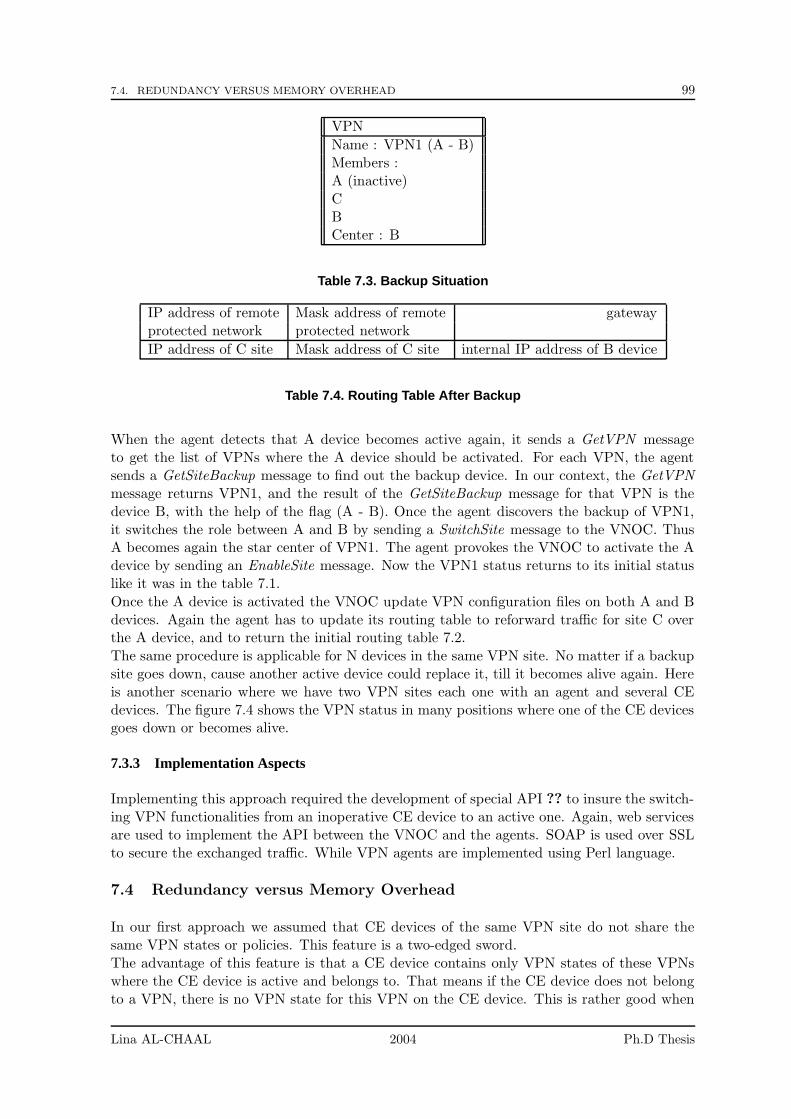
7.4. REDUNDANCY VERSUS MEMORY OVERHEAD 99
VPN
Name : VPN1 (A - B)Members :A (inactive)CBCenter : B
Table 7.3. Backup Situation
IP address of remote Mask address of remote gatewayprotected network protected network
IP address of C site Mask address of C site internal IP address of B device
Table 7.4. Routing Table After Backup
When the agent detects that A device becomes active again, it sends a GetVPN messageto get the list of VPNs where the A device should be activated. For each VPN, the agentsends a GetSiteBackup message to find out the backup device. In our context, the GetVPNmessage returns VPN1, and the result of the GetSiteBackup message for that VPN is thedevice B, with the help of the flag (A - B). Once the agent discovers the backup of VPN1,it switches the role between A and B by sending a SwitchSite message to the VNOC. ThusA becomes again the star center of VPN1. The agent provokes the VNOC to activate the Adevice by sending an EnableSite message. Now the VPN1 status returns to its initial statuslike it was in the table 7.1.
Once the A device is activated the VNOC update VPN configuration files on both A and Bdevices. Again the agent has to update its routing table to reforward traffic for site C overthe A device, and to return the initial routing table 7.2.
The same procedure is applicable for N devices in the same VPN site. No matter if a backupsite goes down, cause another active device could replace it, till it becomes alive again. Hereis another scenario where we have two VPN sites each one with an agent and several CEdevices. The figure 7.4 shows the VPN status in many positions where one of the CE devicesgoes down or becomes alive.
7.3.3 Implementation Aspects
Implementing this approach required the development of special API ?? to insure the switch-ing VPN functionalities from an inoperative CE device to an active one. Again, web servicesare used to implement the API between the VNOC and the agents. SOAP is used over SSLto secure the exchanged traffic. While VPN agents are implemented using Perl language.
7.4 Redundancy versus Memory Overhead
In our first approach we assumed that CE devices of the same VPN site do not share thesame VPN states or policies. This feature is a two-edged sword.The advantage of this feature is that a CE device contains only VPN states of these VPNswhere the CE device is active and belongs to. That means if the CE device does not belongto a VPN, there is no VPN state for this VPN on the CE device. This is rather good when
Lina AL-CHAAL 2004 Ph.D Thesis
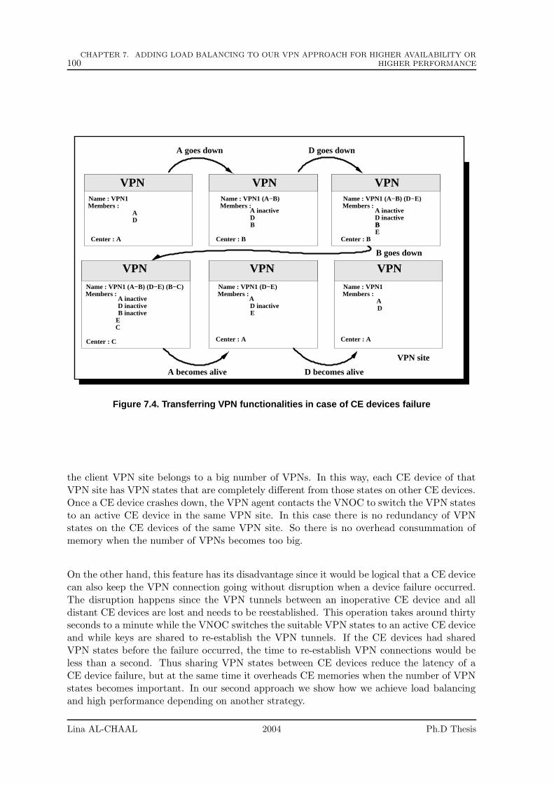
100CHAPTER 7. ADDING LOAD BALANCING TO OUR VPN APPROACH FOR HIGHER AVAILABILITY OR
HIGHER PERFORMANCE
VPN site
Name : VPN1
VPN VPN VPN
VPNVPNVPNName : VPN1 (A−B) (D−E) (B−C) Name : VPN1Name : VPN1 (D−E)
Name : VPN1 (A−B) (D−E)Name : VPN1 (A−B)Members : Members : Members :
Members : Members : Members :
AD
A inactive A inactive
BBE
D inactiveA inactive
B inactive
CE
D inactiveE
A D
Center : A
Center : A
Center : B Center : B
Center : C Center : A
DB
D inactive
A
A goes down
A becomes alive D becomes alive
B goes down
D goes down
Figure 7.4. Transferring VPN functionalities in case of CE devices failure
the client VPN site belongs to a big number of VPNs. In this way, each CE device of thatVPN site has VPN states that are completely different from those states on other CE devices.Once a CE device crashes down, the VPN agent contacts the VNOC to switch the VPN statesto an active CE device in the same VPN site. In this case there is no redundancy of VPNstates on the CE devices of the same VPN site. So there is no overhead consummation ofmemory when the number of VPNs becomes too big.
On the other hand, this feature has its disadvantage since it would be logical that a CE devicecan also keep the VPN connection going without disruption when a device failure occurred.The disruption happens since the VPN tunnels between an inoperative CE device and alldistant CE devices are lost and needs to be reestablished. This operation takes around thirtyseconds to a minute while the VNOC switches the suitable VPN states to an active CE deviceand while keys are shared to re-establish the VPN tunnels. If the CE devices had sharedVPN states before the failure occurred, the time to re-establish VPN connections would beless than a second. Thus sharing VPN states between CE devices reduce the latency of aCE device failure, but at the same time it overheads CE memories when the number of VPNstates becomes important. In our second approach we show how we achieve load balancingand high performance depending on another strategy.
Lina AL-CHAAL 2004 Ph.D Thesis
7.5. OUR SECOND APPROACH: LOAD BALANCING AND HIGH PERFORMANCE ARCHITECTURE 101
7.5 Our Second Approach: Load Balancing and High Performance Archi-tecture
In this approach we inherit the concept of a high performance cluster. One way of imple-menting a high performance cluster is to make each node in the cluster receive each packet,and then each node discards packets that it knows will be handled by another node in thecluster.Since the equipment using the cluster must not require modification, each node will receive allthe packets only if a broadcast or shared Ethernet-MAC address is used. Again, broadcastingall packets sent to the cluster to other hosts on the same LAN could cause interference, ashared MAC address is the most favorable solution.Several Linux hosts can share the same Ethernet-MAC address as long as neither tries toforward packets or sent ICMP ’destination unreachable’ messages. In general, if a hostreceives an IP packet destined for an IP address that is not local it will be forwarded ordropped. Equally the sender cannot distinguish between a node hosting or routing severalIP addresses and the shared MAC-address configuration. Thus an ARP request for any IPaddress on either node will return the shared MAC address, and any packet sent to this MACaddress will be received by all nodes but dropped on one.Additional tools are required to implement a high performance cluster. The cluster mustprovide one virtual service address, which must then be shared by all nodes in the cluster.A kernel module must be created that will filter traffic so that each node gets a fair share ofthe traffic (and thus the load).
7.5.1 Hubs or Switches
In the basic Ethernet architecture, all packets sent on the network are seen (and filtered) byeach node. This allows a network analyzer to see all the exchanges on the network. A networkbuild using Hubs works in the same way, and a network analyzer still works as expected.However in a network built with switches, not all packets are seen by all nodes. The switchtries to improve network performance (and security) by tracking the MAC addresses con-nected to each port of the switch. Thus once a switch has detected that a MAC address isconnected to one port, any packets sent to that MAC address will not be forecast to otherports. This is a frequent problem with network analyzers.When a shared MAC address is used with a switch, the switch gets confused. Very fewswitches expect this form of configuration. On occasion, the switch can crash, but in anycase the switch will filter on the MAC address, which prevents the cluster software formworking properly.
7.5.2 Router Example to Better Understand
To better understand our architecture, we prefer to start by a simple example of a routeracting as a firewall. Therefore, we quickly remember the basic concepts of firewalls.
Firewalls
Traditionally there are two types of firewall, proxy-based firewall or packet-filter firewall.The packet filter firewall is the most widely used, since it does not require any changes inthe network, the client applications or in the user’s behavior. A proxy-based firewall doesnot route any packets. Instead users must connect to the proxy on the firewall, and it isthen the proxy that connects to the outside world. A Packet Filter firewall behaves like a
Lina AL-CHAAL 2004 Ph.D Thesis
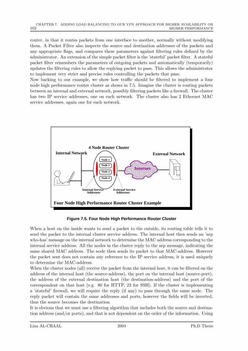
102CHAPTER 7. ADDING LOAD BALANCING TO OUR VPN APPROACH FOR HIGHER AVAILABILITY OR
HIGHER PERFORMANCE
router, in that it routes packets from one interface to another, normally without modifyingthem. A Packet Filter also inspects the source and destination addresses of the packets andany appropriate flags, and compares these parameters against filtering rules defined by theadministrator. An extension of the simple packet filter is the ’stateful’ packet filter. A statefulpacket filter remembers the parameters of outgoing packets and automatically (temporarily)updates the filtering rules to allow the replying packet to pass. This allows the administratorto implement very strict and precise rules controlling the packets that pass.Now backing to our example, we show how traffic should be filtered to implement a fournode high performance router cluster as shows in 7.5. Imagine the cluster is routing packetsbetween an internal and external network, possibly filtering packets like a firewall. The clusterhas two IP service addresses, one on each network. The cluster also has 2 Ethernet MACservice addresses, again one for each network.
����������������������������������������������������������������������������������������������������������������������������������������������������������������������������������������������������������������������������������������������������������������������������������������������������������������������������������
����������������������������������������������������������������������������������������������������������������������������������������������������������������������������������������������������������������������������������������������������������������������������������������������������������������������������������
AddressesInternal Service
AddressesExternal Service
Internet
Internal Network4 Node Router Cluster
External Network
Four Node High Performance Router Cluster Example
Node 1
Node 2
Node 3
Node 4
Figure 7.5. Four Node High Performance Router Cluster
When a host on the inside wants to send a packet to the outside, its routing table tells it tosend the packet to the internal cluster service address. The internal host then sends an ’arpwho-has’ message on the internal network to determine the MAC address corresponding to theinternal service address. All the nodes in the cluster reply to the arp message, indicating thesame shared MAC address. The node then sends its packet to that MAC-address. Howeverthe packet sent does not contain any reference to the IP service address, it is used uniquelyto determine the MAC-address.When the cluster nodes (all) receive the packet from the internal host, it can be filtered on theaddress of the internal host (the source-address), the port on the internal host (source-port),the address of the external destination host (the destination-address) and the port of thecorrespondent on that host (e.g. 80 for HTTP, 22 for SSH). If the cluster is implementinga ’stateful’ firewall, we will require the reply (if any) to pass through the same node. Thereply packet will contain the same addresses and ports, however the fields will be inverted,thus the source becomes the destination.It is obvious that we must use a filtering algorithm that includes both the source and destina-tion address (and/or ports), and that is not dependent on the order of the information. Using
Lina AL-CHAAL 2004 Ph.D Thesis
7.5. OUR SECOND APPROACH: LOAD BALANCING AND HIGH PERFORMANCE ARCHITECTURE 103
both port and IP address information provides a more even distribution of the load over thecluster, however port information only exists for UDP and TCP communications. Thereforewe use a hashing function that takes the source and destination address and produces anumber between 1 and 4.
Each node in the cluster is configured to accept packets that produce a particular hash-value,thus one node will accept to process the packet from the internal node and passes it on tothe normal packet-handling routines, where it may again be filtered to verify that it complieswith any firewall configuration. The firewall software may additionally store the addressinformation from the packet, to create a state table to help filter returning packets.
If the packet passes the firewall filtering it will be transmitted on the external interface.When a reply is generated, all the nodes in the cluster will again receive it. The same hashalgorithm will be applied and the same node will accept the packet, allowing the packet tobe processed by the routing and firewall software. If it again passes the firewall filters, it willbe transmitted on the internal network.
If one of the nodes in the cluster fails, another node must take over its role. This means thatthe replacement node must accept two hash-values. If 3 nodes fail, the remaining node mustaccept all hash-values. Thus the hash values are the real cluster resources, and the clustermust act so that all the hash values are (almost) continuously ”active”.
If only 3 nodes are active in a cluster, then with a hash-value from 1 to 4, one node musttake half the cluster load. However if a larger range of hash-values is used, say 0 to 31, thenthe load can be more evenly divided between the remaining nodes in the cluster. This can beautomated by broadcasting the hash-values active on each node, and performing a takeoverof a hash-value if a node detects that it is not already active.
In this scenario, no packets are ever sent or received with the IP service addresses. Eachnode must be accessible using alternative host-based IP addresses.
7.5.3 VPN Gateway Cluster
In this section, we show how the architecture outlined in the previous section would besufficient to provide a high performance VPN Gateway and how does a VPN Gateway differsfrom a normal router.
The figure 7.6 shows a road warrior connecting to an internal mail server to download mail,while an internal client connects to the Internet.
Tunnel Initiated by the Road Warrior
The road warrior first establishes an IPSEC tunnel with the cluster, and then uses thistunnel to send packets into the internal network. The IPSEC tunnel is established betweenthe external cluster service address and the Internet address of the PC, called the ’peerendpoint address’. The road warrior typically connects to the Internet via a dial-up Internetconnection, and so the peer endpoint address is probably assigned dynamically by whateverISP used. The peer endpoint address is always a routable public IP address, as opposed toprivate, non-routable address often used for a small company’s internal network.
Once the tunnel is set up, the road warrior uses an internal IP address, assigned by thenetwork administrator of the internal network. Thus when the mail server receives a packet,the source address can be verified to belong to the internal network in general, and theroad-warrior user specifically.
The implementation of a shared MAC-address High Performance cluster in this scenario iscomplex. The tunnel endpoint is hosted by one of the cluster nodes. This node can be chosen
Lina AL-CHAAL 2004 Ph.D Thesis

104CHAPTER 7. ADDING LOAD BALANCING TO OUR VPN APPROACH FOR HIGHER AVAILABILITY OR
HIGHER PERFORMANCE
�����������������������������������������������������������������������������������������������������������������������������������������������������������������������������������������������������������������������������������������������������������������������������������������������������������
�����������������������������������������������������������������������������������������������������������������������������������������������������������������������������������������������������������������������������������������������������������������������������������������������������������
AddressesInternal Service
AddressesExternal Service
Internet
VPN Gateway Cluster
Internal Network
Mail Server
Internal Client
Road Warrior
Web Server
High Performance VPN Gateway Cluster
IPsec tunnelNode 1
Node 2
Node N
Figure 7.6. A High Performance VPN Gateway Cluster
by generating a hash-value from the source address, which is the peer endpoint address, ofthe packets sent from the road-warrior to the cluster service IP address. Packets recoveredfrom the tunnel can be sent from the node hosting the endpoint without any problem.
However reply packets, which can only be handled by the tunnel hosting the endpoint, willprobably not generate a hash-value corresponding to the node hosting the tunnel endpoint.To get the same hash-value, the hashing function should be applied on the destination addressof the tunnel endpoint, that is usually different from the destination address of the repliedpackets and is not specified in the replied packets. Actually a tunnel does not necessarilycorrespond to one isolated IP address as in the road warrior example. In reality, a tunnelcorresponds to a subnet, thus making any attempt at generating a hash-value from packetsto be forwarded over a tunnel very difficult.
The destination address on these reply packets must match the subnet definition correspond-ing to the tunnel, and the tunnel corresponds to a peer tunnel endpoint address. Thus whenthe tunnel is established, an additional input filter could be activated with the subnet def-inition. When a packet is received by the internal network that matches that subnet, it isaccepted on the node hosting the tunnel since it has the additional filter definition. Howeverthe other nodes in the cluster do not have the additional filter and apply the normal hash-value filter. One other node could also accept the packet, based on its hash-value, howeveradditional filters could prevent these packets from being accepted on any node not hostingthe tunnel endpoint.
Tunnel Initiated by the VPN Gateway Cluster
In addition the inverse scenario must be considered, where it is the VPN Gateway Clusterthat initiates the tunnel. The tunnel is initiated as required to send a packet received fromthe internal network. However the parameters of the tunnel, which include the peer addressand the subnet definition, are known when the VPN software is activated. Thus a tablecan be generated statically, containing the subnet definition and the hash-value that would
Lina AL-CHAAL 2004 Ph.D Thesis
7.6. PARTIAL CONCLUSIONS 105
be generated if a packet was received from that peer. Thus when a packet is received onthe internal interface that corresponds to a subnet listed in this table, the filter can use thehash-value listed in the table instead of generating a hash-value from the addresses in thepacket. This allows all the nodes except one to drop the packet.For any packet received on the external interface with a destination address that wouldnormally be routed to the internal network, the normal hash-value algorithm can be applied.Similarly any packet received on the internal interface that would be sent to the externalnetwork can also be treated in the same manner. In fact, any packet received on any non-IPSEC interface, and that would be forwarded to any non-IPSEC interface, can be treatedusing the basic hash-value mechanism.
7.6 Partial Conclusions
Most often dynamic routing protocols can take up to a minute to learn about a devicefailure. Our first approach, however, does not need to rely on dynamic routing to recoverfrom a connection failure. It gets benefit of the dynamic feature of our VPN approach andthe redundancy at the physical level by using several CE devices on the same VPN site.VPN agents in our approach constantly monitor CE devices, so a device failure is rapidlyidentified and fail over can be accomplished in a few seconds. However a redundancy atthe logical VPN layer could be added to like in our second approach, by sharing the sameVPN states among CE devices of the same VPN site to minimize that down time, althoughmemory overhead becomes more noticeable 7.4. But the benefits we get by applying oursecond proposal become more important when the MOP handles lots of VPN sites, since theVPN gateway in this model handles by itself the load balancing without interfering with theMOP. However, a mix of the two strategies could come up with better solution.
Lina AL-CHAAL 2004 Ph.D Thesis

106CHAPTER 7. ADDING LOAD BALANCING TO OUR VPN APPROACH FOR HIGHER AVAILABILITY OR
HIGHER PERFORMANCE
Lina AL-CHAAL 2004 Ph.D Thesis

Part III
Discussion, Conclusions, and FutureWork
107

Chapter 8
Discussion, Conclusions and FutureWorks
Contents
8.1 General Discussion . . . . . . . . . . . . . . . . . . . . . . . . . . . 110
8.1.1 Security . . . . . . . . . . . . . . . . . . . . . . . . . . . . . . . . . . 110
8.1.2 Scalability . . . . . . . . . . . . . . . . . . . . . . . . . . . . . . . . . 111
8.1.3 Robustness . . . . . . . . . . . . . . . . . . . . . . . . . . . . . . . . 111
8.1.4 Performance . . . . . . . . . . . . . . . . . . . . . . . . . . . . . . . 112
8.1.5 Relationship with Active and Programmable Networks . . . . . . . . 113
8.1.6 Other Related Works . . . . . . . . . . . . . . . . . . . . . . . . . . . 113
8.2 Another field of application: NAT and its Challenges . . . . . . 113
8.2.1 Discussion . . . . . . . . . . . . . . . . . . . . . . . . . . . . . . . . . 113
8.2.2 Contributions and Future Works . . . . . . . . . . . . . . . . . . . . 114
8.3 Another field of application: Introducing Dynamic FirewallsManagement to our CE-based VPN Model . . . . . . . . . . . . . 115
8.3.1 Improving Filtering in our VPN Model . . . . . . . . . . . . . . . . . 115
8.3.2 Needs for Dynamic Firewall Management . . . . . . . . . . . . . . . 116
8.4 Another field of application: Security and VoIP . . . . . . . . . 117
8.4.1 Discussion . . . . . . . . . . . . . . . . . . . . . . . . . . . . . . . . . 117
8.4.2 Contributions and Future Works . . . . . . . . . . . . . . . . . . . . 117
We have so far introduced and analyzed our CE-based VPN proposal for offering dynamic,secure and well-managed services in an easy and transparent way for customers. We alsoapplied and implemented our proposal in various domains. In this chapter, we concludethe dissertation by revisiting the lessons learned from this work and presenting direction forfuture researches in this area. We discuss several key points that were raised and classifythem in decreasing order of importance from our point of view. For each of them, we identifyour contributions and, when applicable, future works.
109
110 CHAPTER 8. DISCUSSION, CONCLUSIONS AND FUTURE WORKS
8.1 General Discussion
In this dissertation, we have presented the CE-based VPN model that shifts the VPN supportfrom ISP core networks to customer equipments CE devices. Our proposal builds an overlaynetwork over physical access and interconnection networks, and offers an abstraction levelbetween the information system (e.g. customers) and physical networks (e.g. ISP networks),creating a complete independence between them. This overlay network is built over theInternet by using IPsec tunnels. To configure and maintain these tunnels in a large scaleenvironment, a central management point called the NOS has been developed for this purpose.The NOS creates secure SSH management tunnels to VPN gateways in order to provision,configure and manage them dynamically. This dynamic feature saves the need for manualinterventions, and simplifies the management of VPN topologies.
We achieved many benefits when applying our VPN proposal in two vast domains: theGroup Communication Services and the Web Services. In Group Communication Services,we focused on many challenges that are usually neglected in the group communication servicesproposals like security of multicast. We showed how our approach could effectively solve thesechallenges and significantly reduce time consuming tasks when building group topologies.
In Web Services, we showed that our model is suited to web services business needs andleverages many of web services deployment limitations. A key point is that new services canbe added quickly without making any change to the implementation of the existing interfaces.
We now discuss several key aspects:
8.1.1 Security
Discussion
A well-secure VPN model always requires a well-managed system. In general, security is nota single technology but an integration of several technologies combined with managementpolicy that provides protection balanced with acceptable risks. How to control security fromthe management perspective, is the most important task of any VPN model. Careful networkdesign and configuration is required. Three key points to achieve this security:
1. The security policies should be generated on behalf of customers, without their knowl-edge or involvement.
2. The update of security policies on VPN gateways, should also be achieved with areasonable small delay.
3. The ability to create coherent security policies is a major step towards establishing areliable VPN.
Contributions and Future Works
The dynamic and centralized feature of our model solves the above problems by deploying thesuitable configuration files to VPN gateways and insuring the update of these files regardingthe VPN topologies. Using the NOS as a central point that collects information on customers,makes security issues easier to handle than in the general case of communications where manyadditional hard problems must be solved. Integrating a dynamic access capability into theNOS highly facilitates security management, since the NOS is informed rapidly when thereis any VPN topology changement. Thus it can update configuration files on the concerned
Lina AL-CHAAL 2004 Ph.D Thesis
8.1. GENERAL DISCUSSION 111
VPN gateway, insuring the establishment and the availability of tunnels. It is worth notingthat centralized overlay approaches, often criticized, find a perfect field of application in VPNenvironments, and have many security benefits.
8.1.2 Scalability
Discussion
Many VPN proposals target a high scalability, which is required for instance with large peer-to-peer applications. This scalability is usually achieved with a hierarchical overlay topology.Scalability in our approach is not an explicit target in. Consequently our approach, asdiscussed in this thesis, is specifically designed to handle a small number of VPNs.However, three different levels of scalability are considered in our approach:
1. Scalability in terms of the number of tunnels required by a VPN on a given CE device.The number of tunnels required for a VPN increases as the number of VPN sitesincreases, with the (default) meshed or star VPN topologies.
2. Scalability in terms of the number of VPNs managed by a CE device.
3. Scalability in terms of the number of VPN customers managed by the NOS. Indeed,the amount of data stored on the NOS and the processing load when a high number ofclients try to access the NOS may exceed the ability of a single point to manage all theVPNs. The more services the NOS provides, the more scalability problem it has.
Contributions and Future Works
Through this thesis, we discussed the scalability of our VPN proposal, even if we do notregard it as a key requirement. We explained how the scalability can be improved by:
• Building a hierarchical VPN topology: in chapter 5, we showed how to apply thissolution thanks to the concept of Virtual Private Routed Network, of VPRN. We alsoshowed how this solution largely improved distribution efficiency with the help of anapplication-level multicast scheme, HBM.
• Applying the concept of load-balancing on CE devices: by using several CE deviceson the same VPN site, a VPN load is shared between them. This solution is effective,since applying cryptographic security mechanisms on a CE device are memory and CPUdemanding tasks.
We have addressed the two kinds of scalability in terms of VPN gateways overhead. Butother aspects must be considered, and in particular the NOS load and the number of VPNsmanaged by the NOS. To that purpose, future works will consider the possibility of havingmultiple NOSs, one primary NOS and one or more secondary NOSs (not for backup) thatwill manage different VPNs. The primary NOS is responsible of VPN topology creation. Thefirst contact with a VPN site is via the primary NOS, and then the primary NOS directs thenew site to the ’closest’ secondary NOS.
8.1.3 Robustness
Discussion
Fault-tolerance and redundancy are critical factors for providing high-availability connec-tivity, which must continue to operate not only during the planned network upgrades andchanges, but also when connections fail unexpectedly due to component failures or attacks.
Lina AL-CHAAL 2004 Ph.D Thesis
112 CHAPTER 8. DISCUSSION, CONCLUSIONS AND FUTURE WORKS
If our VPN model offers a way to alleviate management problems, it also creates otherinstability problems. For instance, a VPN model based on CE devices (usually PCs orworkstations) is intrinsically less robust than one based on provider core networks wherededicated and well administered routers are used. There is a high risk, as the number oftunnels, handled by a VPN gateway, increases, that the topologies be partitioned after theVPN gateway failure. Of course, it depends on which distribution topology (e.g. tree orring) is used. For instance, a VPN gateway failure is a major issue if this VPN gateway isthe center of a VPN topology. Robustness requires that VPN gateway failures be rapidlydiscovered and the reparation be rapidly done.
Contributions and Future Works
Our CE-based model has a major advantage over provider-based models, since it does notrely on a specific connection network or a specific ISP network. For instance, in our model,the packets sent by a VPN gateway, might not follow the same path to reach the remote VPNgateway. Thus, when a failure occurs in the connection network itself, some packets may belost, during the unstability period only, before an alternate route is discovered. This is notthe case if the VPN is attached to a specific path with PPVPN model.VPN gateways are not the only points of failure, the NOS is also vulnerable to failures. Inpractice, one or more secondary backup NOSs, located outside of the VPN service provider’snetwork and periodically synchronized with the central NOS, are used for high reliabilitypurposes.In Chapter 7, we addressed the robustness aspect by using a fast detection and repair mech-anism for VPN gateway failures. An agent located behind the CE devices of a VPN siteis responsible of detecting a CE failure. Upon detecting a failure, restoration schemes thatinclude switching to active VPN gateways, are rapidly sent by the NOS. The dynamic featureof our model plays an important role for repairing such a problem. We also distinguishedbetween two notions: high availability and high performance, and we proposed two kinds ofarchitectures, one for each perspective. The cluster architecture based on a high-performancenotion, introduces some redundancy, which as a side effect, also improves its availability.
8.1.4 Performance
Discussion
Although creating an automatic VPN topology is more effective for creating good data de-livery topologies, many aspects will affect performance in our model:
• Signaling overhead: the automatic creation and update of VPN topologies has negativeeffects on performance, since topologies must reflect the dynamic networking conditionsand the data flow generated dynamically between the VPN gateways and the NOS adda significant overhead (section 13.3).
• Low Internet performance: Heavy-use applications may not be able to maintain ad-equate throughput on a VPN over the Internet. If the performance of the Internetbecomes unsupportable, one possible alternative is to use a provider-based VPN thatuses private backbones instead of the public Internet infrastructure.
Contributions and Future Works
Performance has not been deeply studied in this thesis. Yet we have introduced the ideaof dynamic topology adaptation at the NOS, and we improved our model performance by
Lina AL-CHAAL 2004 Ph.D Thesis
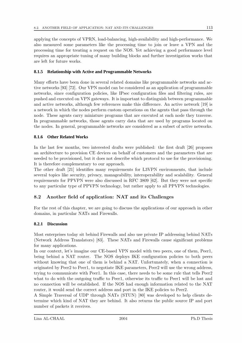
8.2. ANOTHER FIELD OF APPLICATION: NAT AND ITS CHALLENGES 113
applying the concepts of VPRN, load-balancing, high-availability and high-performance. Wealso measured some parameters like the processing time to join or leave a VPN and theprocessing time for treating a request on the NOS. Yet achieving a good performance levelrequires an appropriate tuning of many building blocks and further investigation works thatare left for future works.
8.1.5 Relationship with Active and Programmable Networks
Many efforts have been done in several related domains like programmable networks and ac-tive networks [93] [72]. Our VPN model can be considered as an application of programmablenetworks, since configuration policies, like IPsec configuration files and filtering rules, arepushed and executed on VPN gateways. It is important to distinguish between programmableand active networks, although few references make this difference. An active network [19] isa network in which the nodes perform custom operations on the agents that pass through thenode. These agents carry miniature programs that are executed at each node they traverse.In programmable networks, those agents carry data that are used by programs located onthe nodes. In general, programmable networks are considered as a subset of active networks.
8.1.6 Other Related Works
In the last few months, two interested drafts were published: the first draft [26] proposesan architecture to provision CE devices on behalf of customers and the parameters that areneeded to be provisioned, but it does not describe which protocol to use for the provisioning.It is therefore complementary to our approach.The other draft [21] identifies many requirements for L3VPN environments, that includeseveral topics like security, privacy, manageability, interoperability and scalability. Generalrequirements for PPVPN were also discussed in RFC 3809 [62]. But they were not specificto any particular type of PPVPN technology, but rather apply to all PPVPN technologies.
8.2 Another field of application: NAT and its Challenges
For the rest of this chapter, we are going to discuss the applications of our approach in otherdomains, in particular NATs and Firewalls.
8.2.1 Discussion
Most enterprises today sit behind Firewalls and also use private IP addressing behind NATs(Network Address Translators) [83]. These NATs and Firewalls cause significant problemsfor many applications.In our context, let’s imagine our CE-based VPN model with two peers, one of them, Peer1,being behind a NAT router. The NOS deploys IKE configuration policies to both peerswithout knowing that one of them is behind a NAT. Unfortunately, when a connection isoriginated by Peer2 to Peer1, to negotiate IKE parameters, Peer2 will use the wrong address,trying to communicate with Peer1. In this case, there needs to be some rule that tells Peer2what to do with the outgoing traffic to Peer1, otherwise its traffic to Peer1 will be lost andno connection will be established. If the NOS had enough information related to the NATrouter, it would send the correct address and port in the IKE policies to Peer2.A Simple Traversal of UDP through NATs (STUN) [80] was developed to help clients de-termine which kind of NAT they are behind. It also returns the public source IP and portnumber of packets it receives.
Lina AL-CHAAL 2004 Ph.D Thesis
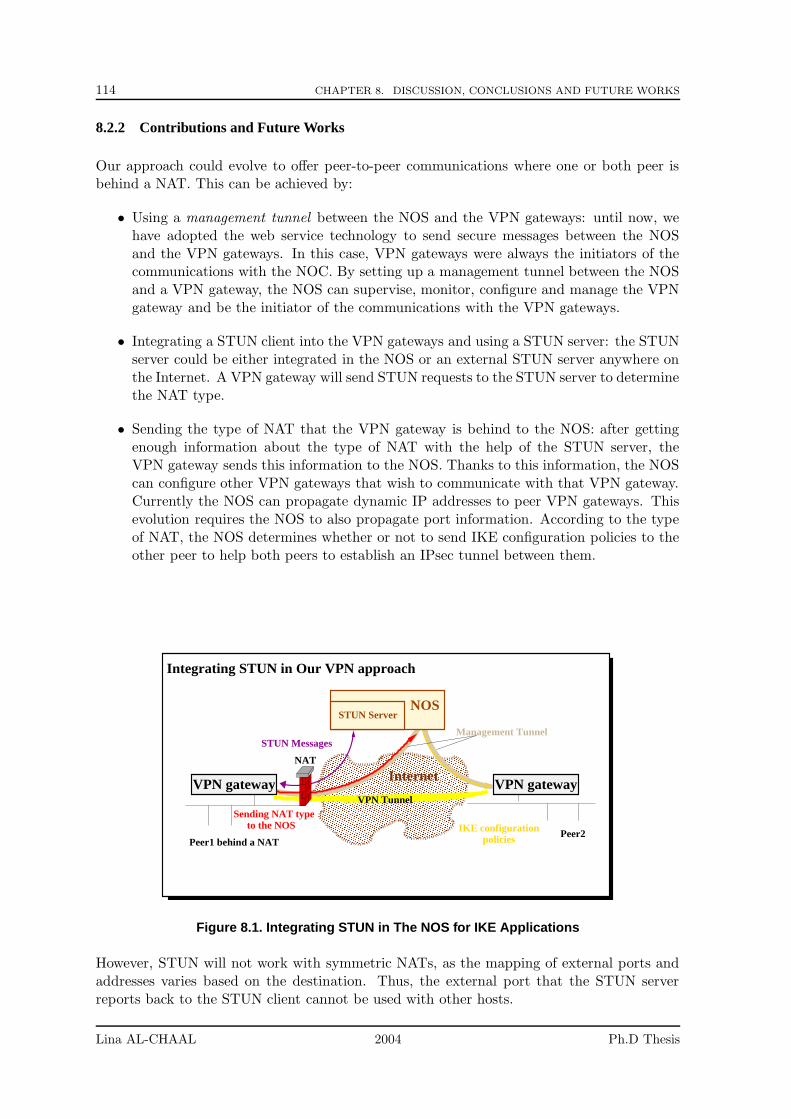
114 CHAPTER 8. DISCUSSION, CONCLUSIONS AND FUTURE WORKS
8.2.2 Contributions and Future Works
Our approach could evolve to offer peer-to-peer communications where one or both peer isbehind a NAT. This can be achieved by:
• Using a management tunnel between the NOS and the VPN gateways: until now, wehave adopted the web service technology to send secure messages between the NOSand the VPN gateways. In this case, VPN gateways were always the initiators of thecommunications with the NOC. By setting up a management tunnel between the NOSand a VPN gateway, the NOS can supervise, monitor, configure and manage the VPNgateway and be the initiator of the communications with the VPN gateways.
• Integrating a STUN client into the VPN gateways and using a STUN server: the STUNserver could be either integrated in the NOS or an external STUN server anywhere onthe Internet. A VPN gateway will send STUN requests to the STUN server to determinethe NAT type.
• Sending the type of NAT that the VPN gateway is behind to the NOS: after gettingenough information about the type of NAT with the help of the STUN server, theVPN gateway sends this information to the NOS. Thanks to this information, the NOScan configure other VPN gateways that wish to communicate with that VPN gateway.Currently the NOS can propagate dynamic IP addresses to peer VPN gateways. Thisevolution requires the NOS to also propagate port information. According to the typeof NAT, the NOS determines whether or not to send IKE configuration policies to theother peer to help both peers to establish an IPsec tunnel between them.
����������������������������������������������������������������������������������������������������������������������������������������������������������������������������������������������������������������������������������������������������������������������������������������������������������������������������������������������������������������������������������������������������������������������������������������������������������������������������������������������������������������������������������������������������������������������������������������������������������������������������������������������������������������������������������������������������������������������������������������������������������������������������������������������������������������������������������������������
����������������������������������������������������������������������������������������������������������������������������������������������������������������������������������������������������������������������������������������������������������������������������������������������������������������������������������������������������������������������������������������������������������������������������������������������������������������������������������������������������������������������������������������������������������������������������������������������������������������������������������������������������������������������������������������������������������������������������������������������������������������������������������������������������������������������������������������������
VPN gateway
NOS
Integrating STUN in Our VPN approach
Management Tunnel
NAT
STUN Messages
to the NOS
VPN gateway
Sending NAT type
policiesIKE configuration
VPN Tunnel
Internet
Peer1 behind a NATPeer2
STUN Server
Figure 8.1. Integrating STUN in The NOS for IKE Applications
However, STUN will not work with symmetric NATs, as the mapping of external ports andaddresses varies based on the destination. Thus, the external port that the STUN serverreports back to the STUN client cannot be used with other hosts.
Lina AL-CHAAL 2004 Ph.D Thesis
8.3. ANOTHER FIELD OF APPLICATION: INTRODUCING DYNAMIC FIREWALLS MANAGEMENT TOOUR CE-BASED VPN MODEL 115
The issue of NAT Traversal is a major problem for the widespread deployment of manyservices like VoIP (more information in Annex 9). Yet, our approach could be a simple wayto deal with this dilemma, and a more detailed investigation could prove insightful results.
8.3 Another field of application: Introducing Dynamic Firewalls Manage-ment to our CE-based VPN Model
Threats on the Internet are increasing at a staggering rate, which means that network man-agement poses many new challenges. One popular tool for accomplishing this task is firewalls.There are two points that we would like to address here: (1) the security improvements ofour VPN model and (2) the general need for a dynamic firewall management system.
8.3.1 Improving Filtering in our VPN Model
Discussion:
Our CE-based VPN model lacks to control the services accessible over the IPsec infrastruc-ture. So far, a tunnel created dynamically by an application in our model, was also availablefor use by any other clients on the same network. When we established a secure tunnel be-tween two VPN sites, we opened the possibility to all machines in the VPN sites to access anyservice turned over these sites. The resulting security is only suited to intranet environments,where all of the sites participating in the VPN belong to the same administrative domainand are trusted.
Contributions and Future Works:
We easily solve this problem by adding a detailed firewall configuration to the VPN gateway.
This solution yields a high robustness, does not incur VPN configuration duplications, andis simple to implement. Packet filtering techniques include stateful packet filtering, whichallows incoming connections to be treated differently from outgoing connections, which isnot possible when configuring an IPsec tunnel. Therefore we chose to allow applications toindicate their service addresses when dynamically creating or joining a VPN. This serviceaddress is then used to generate packet filter rules that are configured on the VPN gateways,as shown in the figure 8.2.
More precisely, a VPN gateway receives requests from the VPN site clients to get the right ofusing a service over the VPN. Once the VPN gateway gets sufficient information, it sends amessage to the NOS asking it to generate the appropriate packet filtering rule for that serviceor application. This message contains the following information: the type of protocol usedby the service, the IP address of the client who asks for the service, the port number of theservice, the identification of the VPN where the firewall rules will be applied and the serviceduration time.
The IP address of the service as well as the identification of the VPN are mandatory param-eters in that message. As soon as the NOS receives the VPN gateway request for enablingthat service, it verifies the access rights of the VPN gateway for that service and the localusers who may access the services offered by this VPN. If the verification is positive, the NOSsends back packet filtering rules to enable that service for the requested VPN.
Thus if the application is trusted, it can be assumed that it will not be unduly lax in pro-viding appropriate information for the services offered and the participation addresses. Inconsequence the IPsec tunnels configured between sites will not be accessible to untrustedelements on any site.
Lina AL-CHAAL 2004 Ph.D Thesis
116 CHAPTER 8. DISCUSSION, CONCLUSIONS AND FUTURE WORKS
���������������������������������������������������������������������������������������������������������������������������������������������������������������������������������������������������������������������������������������������������������������������������������������������������������������������������������������������������������������������������������������������������������������������������������������������������������������������������������������������������������������������������������������������������������������������������������������������������������������������������������������������������������������������������������������������������������������������������������������������������������������������������������������������������������
���������������������������������������������������������������������������������������������������������������������������������������������������������������������������������������������������������������������������������������������������������������������������������������������������������������������������������������������������������������������������������������������������������������������������������������������������������������������������������������������������������������������������������������������������������������������������������������������������������������������������������������������������������������������������������������������������������������������������������������������������������������������������������������������������������
VPN gateway VPN gatewayuntrusted Internet
NOS
Firewall Dynamic Management
VPN Tunnel
Host A Host B
Accept from Src A to Dest B
Filter Rule RequestPacket filteringrules
Accept from Src B to Dest A
��������������������
��������������������
Figure 8.2. Applying Dynamic Management for Firewalls in our VPN Model
Our dynamic VPN management model can be used to develop many types of distributedapplications in an extranet environment. Dynamic VPN creation, when associated with dy-namic packet filtering management, allows applications behind the VPN gateway to securelycommunicate with partner applications on other sites, while preventing unplanned accessbetween other applications on the same sites.
8.3.2 Needs for Dynamic Firewall Management
Discussion:Changing firewalls rules on a big distributed system is a big chore. Because firewalls arerules-based, configuration and manageability are important features, and designing a systemthat scales well in a large distributed environment is still a challenge [24]. A survey of thedefinition and the different types of firewalls can be found in annex [22]. Here are some keypoints that must be considered when managing firewalls:
• Detecting misconfigurations: any firewall misconfiguration can result in the networkbeing vulnerable to attacks. With the vast number of configuration settings, errorscan easily creep into the system. Configuration errors can become even more prevalentwhen multiple administrators make changes to the firewall settings. A well-managedsolution should compare the firewall configuration file with identified security policiesto ensure that the firewall configuration is correct.
• Deploying coherent configuration rules: large enterprises will have numerous firewalls todeploy, and will likely want to implement similar policies in many locations. Consistentand coherent firewall rules will be important for insuring a good functionality of thefirewalls.
• Providing monitoring: in large network environments, using multiple applications tomonitor network activity can delay the problem resolution. A fast identification of fire-wall issues is needed.
Lina AL-CHAAL 2004 Ph.D Thesis
8.4. ANOTHER FIELD OF APPLICATION: SECURITY AND VOIP 117
Contributions and Future Works:
Our VPN model can address the above challenges, and a central management system seemsto be the best candidate for the following reasons:
• Gathering all firewall-related events, alerts, and other activities into one central locationmakes monitoring tasks much easier. It avoids having the look at numerous eventlogs to identify when attacks are underway, or when configurations are out of date.Additionally, the integrity of this information is easier to guaranty if everything isstored in a secure central repository.
• By using a central management point for firewalls, rule deployment and threats orconfiguration errors can be automated. For example, if the firewall cannot start upproperly due to network problems, a notification message can be sent to the centralpoint.
• Deploying firewall rules is done by a single secure entity, which avoids rule coherencyproblems.
8.4 Another field of application: Security and VoIP
8.4.1 Discussion
IP networks are now used to handle an increasing number of voice calls [84]. Yet, the darkside of the convergence of voice and IP networking is that it is a good melting pot for attacksand threats, not only to customers but also to operators.
Until now, VoIP security has not been particularly addressed, but as VoIP usage becomeswidespread, enterprises and home users will become subject to the same security risks thathave affected data networks. This is largely due to the fact that next-generation voice net-works are IP based and all IP protocols for sending voice traffic contain flaws [79].
Security is a critical feature for deploying VoIP services [61], since it requires the availabilityof administration and management systems to support customers distributed throughout thenetwork, eliminate single points of failure, ensure the highest degree of service availabilityand deploy coherent secure policies.
Moreover, service providers must find an acceptable method for sending VoIP traffic throughfirewalls, which can inhibit and even block VoIP packets due to their inherent security func-tions. NATs also create similar problems [78]. Another significant challenge is the testing ofVoIP services in a highly distributed and diverse environment.
The above challenges are configuration problems, that requires a well-managed system toovercome.
8.4.2 Contributions and Future Works
VoIP seems to be a good field of application of our VPN model. By adopting a media proxyserver into the NOS, or by interacting with the proxy servers that help to route SIP requests,the NOS will be able to get information about two end-hosts that intend to communicateusing VoIP. The NOS can get this information (1) by identifying end-hosts initiating SIPsessions, during the authentication phase (2) and by having information regarding the VPNthat the end-hosts belong to. Using this information the NOS can react rapidly to deploy thesuitable VPN configuration policies, as well as other services like generating firewall and NATrules on behalf of the end-hosts (as discussed in sections 8.3,8.2). As soon as the policies are
Lina AL-CHAAL 2004 Ph.D Thesis
118 CHAPTER 8. DISCUSSION, CONCLUSIONS AND FUTURE WORKS
deployed, the end-hosts can establish a VPN tunnel between them and send voice packetsover it. Briefly, we believe that the use of our VPN model cuts costs and simplifies thenetwork management requirements for the deployment of VoIP services.
Lina AL-CHAAL 2004 Ph.D Thesis
Chapter 9
Annex
Contents
9.1 Firewalls . . . . . . . . . . . . . . . . . . . . . . . . . . . . . . . . . . 119
9.2 NATs . . . . . . . . . . . . . . . . . . . . . . . . . . . . . . . . . . . . 121
9.3 NATs and VoIP . . . . . . . . . . . . . . . . . . . . . . . . . . . . . 122
9.1 Firewalls
In general, a network firewall is some dedicated hardware or software that prevents unau-thorized access from the outside network to internal individual hosts (personal firewall) orgroups of hosts. Some firewalls also blocks the outgoing flows from unauthorized programsin the protected domain.
Firewalls typically adopt one or more of the following methods:
• Packet Filtering : this type of firewalls inspects each packet going through the firewall(packet filtering is usually hardware implemented) and accepts or reject packets basedon a configured set of access policy. It is done at the network layer (layer three) orthe transport layer (layer four) of the OSI reference model. Packet filtering rules orfilters can be configured to allow or deny traffic based on one or more of the followingvariables: Source or Destination IP address, Protocol type (TCP/UDP) and Source orDestination port.
Most network routers implement some sort of packet filtering, its cheap and fast butdifficult to configure for heightened levels of security. This is because packet filterslook at source and destination IP addresses, ports and protocols but not at content orpurpose of the packets (e.g. it does not does not know that the packet is an outgoingOutlook email). Packet filtering firewalls are prone to different kinds of attacks: the IPspoofing, ICMP tunneling and buffer overruns.
• Stateful Packet Inspection (SPI): instead of inspecting each data packet independently,SPI filtering looks at certain characteristics of flow of data packets and compares againstits sets of configured rules. This allows more intelligent decisions but usually requiresuser intervention from within the firewall software and anyway is more costly in termsof resources needed since a state is maintained for each flow. A connection table tracks
119
120 CHAPTER 9. ANNEX
individual flows, enabling policy checks that extend across series of packets. For exam-ple, TCP ACK packets not preceded by a TCP SYN packet with a correct sequencenumber can be blocked. The SPI firewall examines packets from the network layer tothe application layer of the OSI model. SPI rules or filters can be configured to allow ordeny traffic based on one or more of the following variables: Source or Destination IPaddress, Protocol type (TCP/UDP), Source or Destination port and Connection state.
When a packet passes through the firewall, it is examined and fed into a dynamic statetable where it is stored. The packet is compared to rules and filters then it is evaluatedusing the state table to know if it is already part from a valid and established connection.Thus the connection state is derived from gathered information from previous packets.
• Application Level Proxy Server : with a pure application proxy, no traffic at all goesthrough the firewall. Instead, the application proxy behaves like a server to clientson the trusted network and like a client to servers outside the trusted network. Thusan application proxy is an intermediary application that secures the data traffic goingin and out of a system from a particular application (e.g. MS Outlook ). When anapplication needs to send data to the Internet, the proxy server performs the connectionand pass/fails the transaction based on earlier user configuration.
Application proxy firewalls permit as much granularity as anyone could desire. Forexample, lists of specific URLs can be blocked from certain subnets, or FTP clientscan be restricted from PUTs, but permitted to execute GETs. Added advantages ofApplication-layer operation include the ability to require strong authentication beforeconnecting and the ability to create detailed logs of security events.
The most significant weakness of application level proxy is that either the client softwareis modified or the user is instructed to follow special setup procedures in order to makecall to the actual server through the proxy server.
• Transparent Proxy Server : this solution is motivated by the desire to force clients touse the proxy, whether they want or not, or because we want them to use the proxywithout their knowledge, or because we do not want to update the settings of hundredsof applications. With this kind of proxy, a client thinks that he is talking to the originserver when he sends a request to the server. Actually the client’s request is interceptedby the proxy who takes the broker’s role between the client and the server. With thismodel, the server itself knows that a proxy is involved in the middle since it receives therequest with proxy IP address, not with the client IP address. The big disadvantageof this approach is to teach the transparent proxy how to redirect connections to thesuitable servers.
• Adaptive Proxies (A.K.A. dynamic proxies): combining the merits of both applicationgateways/proxies and packet filtering, adaptive proxies work by inspecting the firstpart of a connection at the application layer to make allow or deny decisions. Thensubsequent packets are inspected at the network layer and allowed or denied at thatlayer. Like stateful packet inspection, adaptive proxies examine packets and then feedthe information into dynamic state tables where the information is stored. The datain the table is then used to evaluate subsequent packets from the same connection. Ifpackets are considered part of a new connection, they are passed back up to the appli-cation layer and inspected there. In this way, it is always the adaptive proxy, workingat the application layer, that inspects and makes allow or deny decisions for each newconnection. Only after the adaptive proxy on the application layer has approved thesession, does it pass to the less secure but faster packet filter on the network layer.
Lina AL-CHAAL 2004 Ph.D Thesis
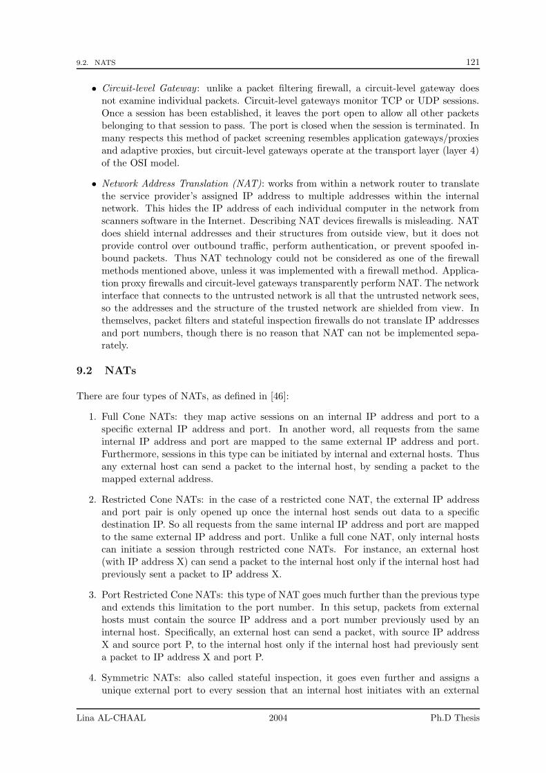
9.2. NATS 121
• Circuit-level Gateway : unlike a packet filtering firewall, a circuit-level gateway doesnot examine individual packets. Circuit-level gateways monitor TCP or UDP sessions.Once a session has been established, it leaves the port open to allow all other packetsbelonging to that session to pass. The port is closed when the session is terminated. Inmany respects this method of packet screening resembles application gateways/proxiesand adaptive proxies, but circuit-level gateways operate at the transport layer (layer 4)of the OSI model.
• Network Address Translation (NAT): works from within a network router to translatethe service provider’s assigned IP address to multiple addresses within the internalnetwork. This hides the IP address of each individual computer in the network fromscanners software in the Internet. Describing NAT devices firewalls is misleading. NATdoes shield internal addresses and their structures from outside view, but it does notprovide control over outbound traffic, perform authentication, or prevent spoofed in-bound packets. Thus NAT technology could not be considered as one of the firewallmethods mentioned above, unless it was implemented with a firewall method. Applica-tion proxy firewalls and circuit-level gateways transparently perform NAT. The networkinterface that connects to the untrusted network is all that the untrusted network sees,so the addresses and the structure of the trusted network are shielded from view. Inthemselves, packet filters and stateful inspection firewalls do not translate IP addressesand port numbers, though there is no reason that NAT can not be implemented sepa-rately.
9.2 NATs
There are four types of NATs, as defined in [46]:
1. Full Cone NATs: they map active sessions on an internal IP address and port to aspecific external IP address and port. In another word, all requests from the sameinternal IP address and port are mapped to the same external IP address and port.Furthermore, sessions in this type can be initiated by internal and external hosts. Thusany external host can send a packet to the internal host, by sending a packet to themapped external address.
2. Restricted Cone NATs: in the case of a restricted cone NAT, the external IP addressand port pair is only opened up once the internal host sends out data to a specificdestination IP. So all requests from the same internal IP address and port are mappedto the same external IP address and port. Unlike a full cone NAT, only internal hostscan initiate a session through restricted cone NATs. For instance, an external host(with IP address X) can send a packet to the internal host only if the internal host hadpreviously sent a packet to IP address X.
3. Port Restricted Cone NATs: this type of NAT goes much further than the previous typeand extends this limitation to the port number. In this setup, packets from externalhosts must contain the source IP address and a port number previously used by aninternal host. Specifically, an external host can send a packet, with source IP addressX and source port P, to the internal host only if the internal host had previously senta packet to IP address X and port P.
4. Symmetric NATs: also called stateful inspection, it goes even further and assigns aunique external port to every session that an internal host initiates with an external
Lina AL-CHAAL 2004 Ph.D Thesis
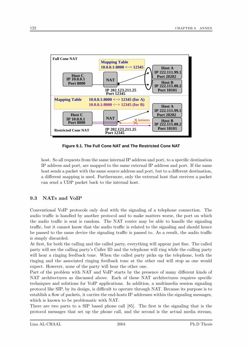
122 CHAPTER 9. ANNEX
Mapping Table10.0.0.1:8000 <−> 12345
Host AIP 222.111.99.1
Port 20202
Host BIP 222.111.88.2
Port 10101
NAT
Restricted Cone NAT
Port 8000IP 10.0.0.1
Host C
IP 202.123.211.25Port 12345
B intiates
Mapping Table 10.0.0.1:8000 <−> 12345 (for A)10.0.0.1:8000 <−> 12345 (for B)
Host AIP 222.111.99.1
Port 20202
Host BIP 222.111.88.2
Port 10101
Port 8000IP 10.0.0.1
Host CNAT
Full Cone NAT
IP 202.123.211.25Port 12345
Figure 9.1. The Full Cone NAT and The Restricted Cone NAT
host. So all requests from the same internal IP address and port, to a specific destinationIP address and port, are mapped to the same external IP address and port. If the samehost sends a packet with the same source address and port, but to a different destination,a different mapping is used. Furthermore, only the external host that receives a packetcan send a UDP packet back to the internal host.
9.3 NATs and VoIP
Conventional VoIP protocols only deal with the signaling of a telephone connection. Theaudio traffic is handled by another protocol and to make matters worse, the port on whichthe audio traffic is sent is random. The NAT router may be able to handle the signalingtraffic, but it cannot know that the audio traffic is related to the signaling and should hencebe passed to the same device the signaling traffic is passed to. As a result, the audio trafficis simply discarded.
At first, for both the calling and the called party, everything will appear just fine. The calledparty will see the calling party’s Caller ID and the telephone will ring while the calling partywill hear a ringing feedback tone. When the called party picks up the telephone, both theringing and the associated ringing feedback tone at the other end will stop as one wouldexpect. However, none of the party will hear the other one.
Part of the problem with NAT and VoIP starts by the presence of many different kinds ofNAT architectures as discussed above. Each of these NAT architectures requires specifictechniques and solutions for VoIP applications. In addition, a multimedia session signalingprotocol like SIP, by its design, is difficult to operate through NAT. Because its purpose is toestablish a flow of packets, it carries the end-hosts IP addresses within the signaling messages,which is known to be problematic with NAT.
There are two parts to a SIP based phone call [85]. The first is the signaling that is theprotocol messages that set up the phone call, and the second is the actual media stream,
Lina AL-CHAAL 2004 Ph.D Thesis
9.3. NATS AND VOIP 123
Host AIP 222.111.99.1
Port 20202
Host BIP 222.111.88.2
Port 10101
Port 8000IP 10.0.0.1
Host CNAT
IP 202.123.211.25Port 12345
Port 8000IP 10.0.0.1
Host CNAT
Port Restricted Cone NAT Mapping Table 10.0.0.1:8000 <−> 12345 (for A : 20202 )
Host AIP 222.111.99.1
Port 20202Port 30303
10.0.0.1:8000 <−> 12345 (for A : 30303 )
Symmetric NAT
Mapping Table 10.0.0.1:8000 <−> 12345 (for A 20202)
Port 12345
IP 202.123.211.25Port 45678
10.0.0.1:8000 <−> 45678 (for B 10101)
Figure 9.2. The Port Restricted Cone NAT and The Symmetric NAT
Real-Time Transport Protocol (RTP) packets that travel directly between the end devices.The real problem is in the second part. In the case of RTP, the SIP message body containsthe information that the endpoints need in order to communicate directly with each other.The end point clients fill in that information according to what they know about themselves.A client sitting behind a NAT knows only its internal IP address and port number, and thatis what it includes in the Session Description Protocol (SDP) [43] body of the outgoing SIPmessage. When the destination endpoint wants to start sending packets to the originatingendpoint, it will use the received SDP information containing the internal IP address andport number of the originating endpoint, and since this internal IP address is non routable,packets cannot reach the host.To solve this problem the client must find the NAT mapped public IP address and port numberand include this information into the SDP message instead of its internal information.To determine its external IP:port, the client asks a server, usually called NAT Probe, sittingoutside the NAT on the public Internet, how it sees the source of a packet coming from him.STUN protocol was develop for setting up such kind of server. With the help of this protocol,a STUN client sends test messages to a STUN server on the Internet. From the STUN server’sreplies, the client learns the type of NAT used, as well as the outbound address and portassociated with the client.
Lina AL-CHAAL 2004 Ph.D Thesis

124 CHAPTER 9. ANNEX
Lina AL-CHAAL 2004 Ph.D Thesis

Part IV
Resume en francais
125

Resume etendu francais
Avertissement : ce resume vise a permettre a un lecteur de comprendre l’essentiel dutravail effectue dans cette these. En revanche il ne couvre pas la totalite du travail. Ainsi ilne comporte qu’une introduction au domaine, la presentation de notre proposition, l’etudede deux aspects qui nous ont semble important, et une discussion synthetique finale.Pour tous les autres aspects, a savoir l’etat de l’art du domaine et les autres contributions denotre approche, le lecteur est invite a se referer a la version anglaise de ce document.
127

128
Lina AL-CHAAL 2004 Ph.D Thesis
Chapter 10
Introduction
Contents
10.1 Contexte du travail . . . . . . . . . . . . . . . . . . . . . . . . . . . 129
10.1.1 Les Points Cles d’un Systeme VPN Bien Administre . . . . . . . . . 129
10.1.2 L’Architecture Conceptuelle . . . . . . . . . . . . . . . . . . . . . . . 131
10.2 Buts de ce travail et organisation du document . . . . . . . . . . 132
10.1 Contexte du travail
Le contexte des etudes est celui de l’evolution vers des reseaux multi-services et en particuliercelui de l’evolution de l’Internet. Nous pouvons dire que l’Internet est rentre dans sa deuxiemegeneration avec l’introduction du Web et l’ouverture commerciale du reseau. Cela a engendreune explosion du trafic et du nombre d’utilisateurs et de reseaux, ce qui a engendre desevolutions technologiques pour le rendre scalable. Cette deuxieme generation a egalementvu naıtre l’usage de l’Internet en temps de que reseau d’infrastructure pour l’interconnexionde sites distants d’entreprise. L’Internet offre une infrastructure suffisamment performanteet etendue pour que les entreprises saisissent cette opportunite. Les reseaux prives virtuelsIP, connus sous le nom (IP Virtual Private Networks) IPVPNs se sont fortement developpes.Les VPNs sont sources d’economies car ils remplacent des lignes louees et des appels longuedistance. Ils presentent d’autres avantages comme la possibilite d’integrer au reseau privedes sites qui ne pouvaient l’etre jusqu’alors et ils permettent d’etendre les applications del’intranet en utilisant l’infrastructure Internet a moindre cout.
10.1.1 Les Points Cles d’un Systeme VPN Bien Administre
Trois points de cles pour reussir l’administration d’un VPN, sont: la securite, l’administrationet le dynamisme. Le deploiement de reseaux prives sur des infrastructures partagees voirepubliques comme Internet necessite des precautions imperatives pour proteger les systemesconnectes a l’infrastructure partagees et les echanges qui vont prendre place sur cette in-frastructure. Les solutions retenues s’appuient sur plusieurs protocoles de securite, tel queL2TP, PPTP ou encore IPsec. IPsec, une suite de protocoles de securite definie par l’IETF(RFC2401-RFC2412), est le protocole utilise dans notre approche grace a ces avantages surles autres protocoles.
129
130 CHAPTER 10. INTRODUCTION
D’autre part, l’etude d’une solution VPN necessite une bonne maıtrise de l’architecture dureseau a modifier ou a construire. L’administration est un element cle au deploiment desVPNs et tout particulierement tout ce qu’il concernce les services de groupes de communica-tions. La mise en place d’une solution bien administree est reliee avec les points suivants:
• Politique: le systeme d’administration doit avoir le pouvoir de convertir les politiquesde configuration a des regles appliquees sur les passerelles VPNs. La securite etl’attenuation des attaques sont aussi basees sur les politiques.
• Configuration: l’approvisionnement et la configuration des equipements VPN doiventetre faits dans une maniere automate et appliques sur les passerelles VPNs.
• Deploiement rentable: dans un systeme administre, il faut avoir un mechanism pourenvoyer, deployer et mettre-a-jour les fichiers de configuration.
• Connaisance des topologies VPNs: plusieurs types de topologies doivent etre supportes.On distingue les VPN mailles et les VPN en etoile qui correspondent respectivementa des topologies de liaisons virtuelles entre sites soit de type n vers m ( reseau maille)soit de type n vers 1 (reseau en etoile).
• Reajustement rapide: agilite et une forte reactivite aux changements dans les topolo-gies VPNs doivent declencher le mis-a-jour des fichiers de configuration sur certainespasserelles VPNs.
• Surveillance: l’environment securise doit etre mise sous controle et sous surveillance.Une automatisation de la supervision et de l’administration des equipements VPN pardes actions a distance sur les equipements VPN installes sur les sites des utilisateursfinals.
En generale, l’administration est avant tout une problematique de connectivite reseau, etd’infrastructure IP. Certains problemes specifiques lies a la technologie utilisee compliquentla mise en oeuvre, par example, la diffusion des fichiers de configuration IPsec bien conherentsentre les differents equipements VPN distribues sur l’Internet.En meme temps, l’Internet entre aujourdhui dans sa troisieme generation, celle qui verra lamise en oeuvre effective de la convergence avec les Telecom (fixes et mobiles) et l’audiovisuel,la generalisation de la mobilite et l’offre de modeles de service reseau evolues. Ces evolutionsqui ont provoque la naıssance de nouvelles applications, citons notamment la generalisationdu ’peer-to-peer’, les jeux distribues, la distribution de contenu multimedia et en particulierla video a la demande. Le deploiment de ces applications, ou le trafic quelles generent devientmajoritaire, requiert en particulier une gestion du trafic plus dynamique se basant sur unemesure permanente de l’evolution de l’etat du reseau.De maniere generale, l’evolution vers l’Internet multi-services et les VPNs requierent laconception d’une nouvelle architecture de reseaux qui prend en charge l’administration dy-namique et la securite du trafic circules sur l’Internet. Cela a constitue les principales moti-vations de nos travaux de recherche.On s’est interesse en particulier a divers domaines couvrant les services de groupes de com-munication et les services Web.Dans le domaine d’une groupe de communication, on s’est interesse a la distribution dutrafic multicast vers les differents clients distribues sur l’Internet. Le multicast IP a eteun sujet chaud de recherche et developpement pendant de nombreuses annees. Malgre celail reste nombre de points ouverts qui rendent son deploiement difficile tel que la securite.D’autre part, une groupe de communicattion qui se compose de differents membres agissant
Lina AL-CHAAL 2004 Ph.D Thesis
10.1. CONTEXTE DU TRAVAIL 131
a differentes echelles de temps, a besoin d’une conception optimale pour traiter ces differentsmembres et leurs interactions de maniere dynamique et unifiee. La conception de notreapproache pour les groupes de communication, a ete notre premier domaine de travail.
Deuxieme domaine aborde etait dans le domaine des services web. Les services web prennentleurs origines dans l’informatique distribuee et dans l’avenement du Web (en particulier lecommerce electronique sur l’Internet). Ils offrent des services applicatifs publies, localises etexecutes sur l’Internet, et accessibles via des protocoles standardises du web par des entitesdistantes (applications ou utilisateurs finaux). Neanmoins des obstacles majeurs a l’adoptiondes services web restent, a savoir la securite et surtout l’administration dynamique des servicesweb.
10.1.2 L’Architecture Conceptuelle
Le modele conceptuel d’architecture de notre approche est un modele services multi niveauxbase sur plusieurs concepts et modeles:
Les Reseaux Intelligents Distribues (Distributed Intelligent Network), DIN:
Le modele DIN fournit un environnement flexible et facile a faire evoluer ([57] , [58]). Cemodele est basee sur la fourniture d’un reseau logique unique qui fournit aux equipementstele-administres installes sur les sites en reseau ou personnels des clients, un ensemble deservices administres.
Ce modele inclut trois composants:
• Reseau Logique: pour les communications entre les differents entites. Ce reseau est unreseau de recouvrement qui se compose sur plusierus reseaux d’interconnection et quifournit un ensemble de services d’administration aux clients, comme la configuration,la surveillance, la qualite de service et le telephone sur IP.
• Reseaux Physiques: ces reseaux sont l’ensemble des reseaux d’interconnection et telecommunicationsqui sont utilises par le reseau logique pour envoyer et recevoir des informations.
• Systeme d’Information: inclus les portables des sites personnels et les passerelles dessites reseaux. Ces equipements sont utilises pour approcher les services d’informationaux clients.
Dans notre cas du service VPN administre un modele DIN est utilise sur l’Internet commedes reseaux physiques, et qui est adapte aux sites VPN et aux element du reseau qui sont desequipements VPN et qui correspondent au systeme d’information. Le reseau logique dansce cas, prend en charge les relations avec les clients et gere leurs services dans une mainereindependante des reseaux physiques utilises.
Tunnel Broker, TB: Un Tunnel Broker [30] est l’equivalent d’un FAI virtuel, qui fournitun service de connexions IP a des utilisateurs. En appliquant le concept du ’Tunnel Broker’dans notre approche, les composants du modele sont:
• Le ’Tunnel Broker’ qui administre les equipements VPN par envoi d’informations deconfiguration.
• Le ’Tunnel Client’ qui est un equipement VPN de site utilisateur qui initialise unedemande de tunnel.
Lina AL-CHAAL 2004 Ph.D Thesis
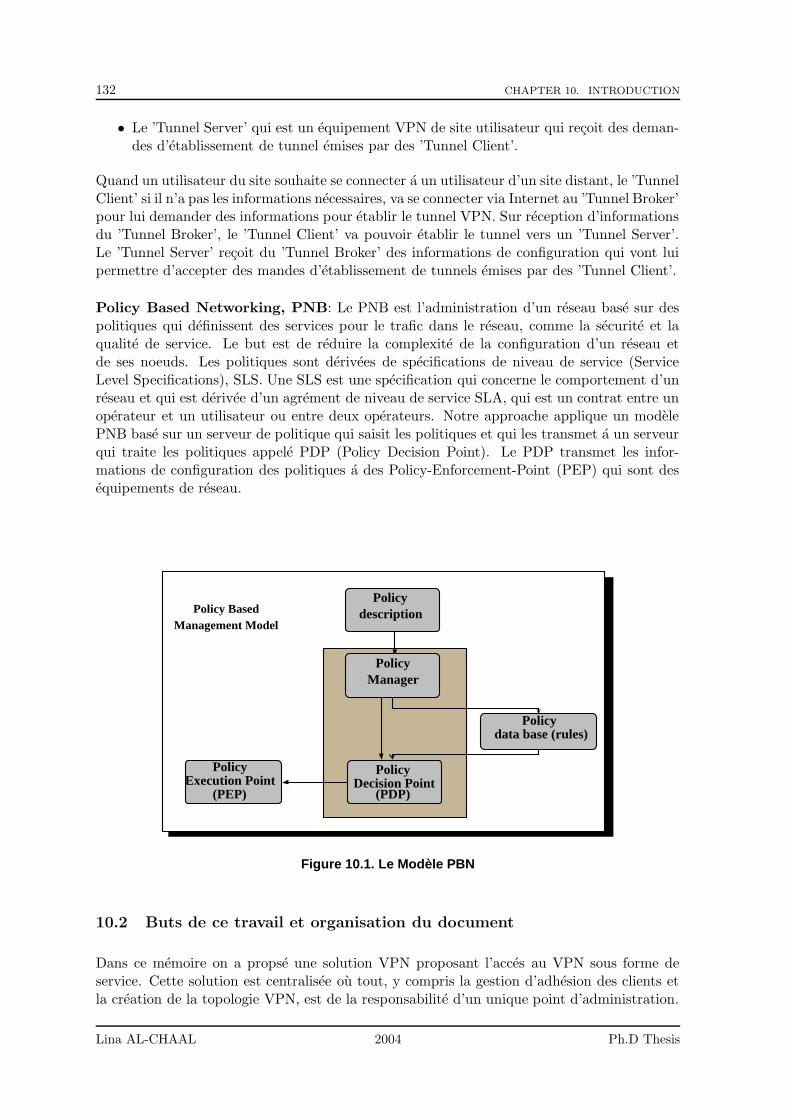
132 CHAPTER 10. INTRODUCTION
• Le ’Tunnel Server’ qui est un equipement VPN de site utilisateur qui recoit des deman-des d’etablissement de tunnel emises par des ’Tunnel Client’.
Quand un utilisateur du site souhaite se connecter a un utilisateur d’un site distant, le ’TunnelClient’ si il n’a pas les informations necessaires, va se connecter via Internet au ’Tunnel Broker’pour lui demander des informations pour etablir le tunnel VPN. Sur reception d’informationsdu ’Tunnel Broker’, le ’Tunnel Client’ va pouvoir etablir le tunnel vers un ’Tunnel Server’.Le ’Tunnel Server’ recoit du ’Tunnel Broker’ des informations de configuration qui vont luipermettre d’accepter des mandes d’etablissement de tunnels emises par des ’Tunnel Client’.
Policy Based Networking, PNB: Le PNB est l’administration d’un reseau base sur despolitiques qui definissent des services pour le trafic dans le reseau, comme la securite et laqualite de service. Le but est de reduire la complexite de la configuration d’un reseau etde ses noeuds. Les politiques sont derivees de specifications de niveau de service (ServiceLevel Specifications), SLS. Une SLS est une specification qui concerne le comportement d’unreseau et qui est derivee d’un agrement de niveau de service SLA, qui est un contrat entre unoperateur et un utilisateur ou entre deux operateurs. Notre approache applique un modelePNB base sur un serveur de politique qui saisit les politiques et qui les transmet a un serveurqui traite les politiques appele PDP (Policy Decision Point). Le PDP transmet les infor-mations de configuration des politiques a des Policy-Enforcement-Point (PEP) qui sont desequipements de reseau.
Policy
Policy
Policy
Policy
Policy
description
Manager
data base (rules)
Decision PointExecution Point(PEP) (PDP)
Management ModelPolicy Based
Figure 10.1. Le Modele PBN
10.2 Buts de ce travail et organisation du document
Dans ce memoire on a propse une solution VPN proposant l’acces au VPN sous forme deservice. Cette solution est centralisee ou tout, y compris la gestion d’adhesion des clients etla creation de la topologie VPN, est de la responsabilite d’un unique point d’administration.
Lina AL-CHAAL 2004 Ph.D Thesis
10.2. BUTS DE CE TRAVAIL ET ORGANISATION DU DOCUMENT 133
Cette solution explique comment construire un reseau VPN en integrant les sites, les postesisoles et les nomades, a l’aide du fonctionnement dynamique de cette approche.Dans cette these, nous presentons une proposition pour etablir un service alternatif de commu-nication de groupe qui deplace le support de multipoint depuis les routeurs vers les extremites.Nous proposons un protocole, appele IVGMP (Internet Virtual Group Management Proto-col) fonctionne au niveau applicatif et fournit un service efficace de distribution multipoint dedonnees sur les VPNs. Avec cette approche, on offre un service de communication de groupea tous les hotes, meme ceux situes dans un site qui n’a pas acces, pour une quelconque raison,au routage multicast natif. En plus, le trafic du groupe sera diffuse en toute securite a traversles tunnels VPNs.Nous presentons aussi la contribution de notre approche dans le domaine des services web quipermet de deployer et surveiller les services web dans une maniere flexible et inter-operable.Nous montrons comment notre approche offre a notre avis suffisamment de souplesse pourpermettre d’administrer les politiques de securite entre les differents elements du service web,tout en evitant les conflits d’interoperabilite. De plus la solution est dynamique et permetde generer les politiques de configurations sans intervention humaine.Les travaux presentes ont donne lieu aux articles ([5], [3], [7], [4], [6]).
Lina AL-CHAAL 2004 Ph.D Thesis

134 CHAPTER 10. INTRODUCTION
Lina AL-CHAAL 2004 Ph.D Thesis
Chapter 11
Notre Approche: CE-based VPNModele
Contents
11.1 Le Principe de Notre Approche . . . . . . . . . . . . . . . . . . . . 135
11.2 Description de Notre Approche . . . . . . . . . . . . . . . . . . . . 136
11.2.1 Utilisation de SSL et IPSec . . . . . . . . . . . . . . . . . . . . . . . 137
11.2.2 Le Reseaux de Base et la Couche Logique . . . . . . . . . . . . . . . 138
11.2.3 Les Messages CE/VNOC . . . . . . . . . . . . . . . . . . . . . . . . 139
11.3 Details d’Implementation . . . . . . . . . . . . . . . . . . . . . . . . 139
11.3.1 L’Architecture SMS . . . . . . . . . . . . . . . . . . . . . . . . . . . 139
11.3.2 L’Architecture SES . . . . . . . . . . . . . . . . . . . . . . . . . . . . 140
Les reseaux VPN Internet sont utilises dans plusieurs types d’applications : Intranet etendus,Extranet, Acces distants.L’utilisation du reseau public Internet comme reseau de transport IP sous jacent rend attractifles IPVPN par:
• des couts de communication tres bas,
• des points d’acces au reseau Internet partout dans le monde, fixes et mobiles,
• et la disponibilite d’acces a Internet a haut debit (ADSL, GPRS).
Dans la suite du document, on va utiliser le terme ’Site VPN’ pour faire referencer au reseaulocal, une branche d’entreprise, un reseau partenaire, ou meme un utilisateur (cas des tra-vailleurs nomades ou a domicile).
11.1 Le Principe de Notre Approche
Le principe de notre approche est de gerer automatiquement la configuration d’equipementsVPN qui ont la charge de gerer des tunnels VPN dans une maniere dynamique et completementetransparente pour les clients. Ces tunnels sont etablis entre les equipements VPN. Ils sontutilises pour transporter les paquets echanges entre des machines d’utilisateurs finals. Les tun-nels empruntent le reseau Internet et assurent une securite robuste des echanges de donnees:authentification forte des equipements VPN source et destination, integrite et confidentialitedes donnees echangees.
135
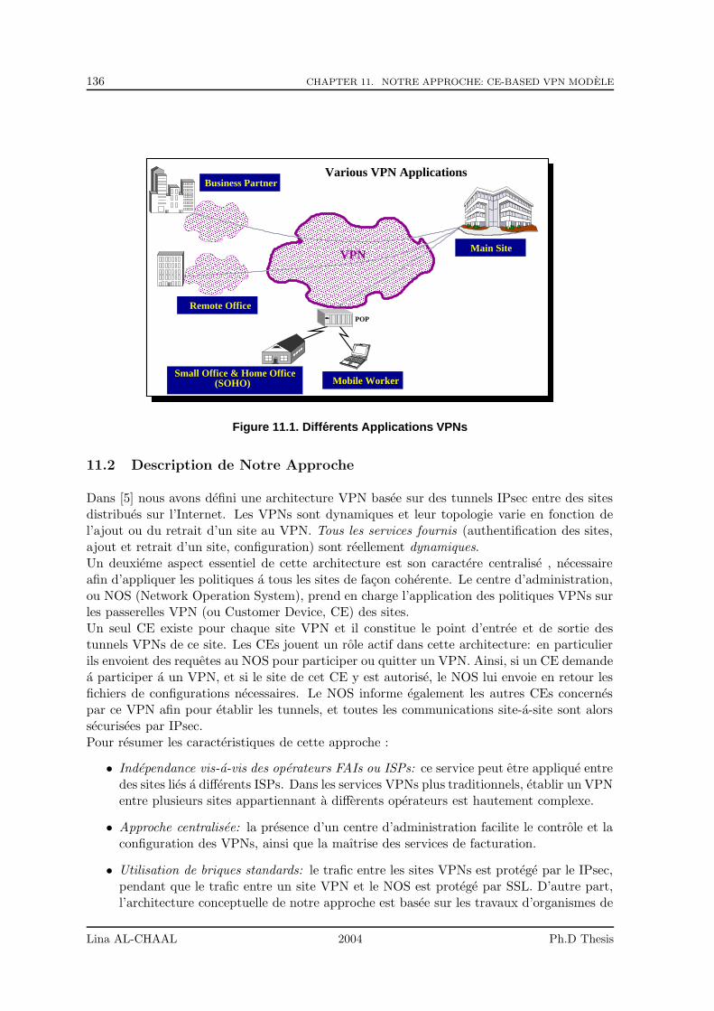
136 CHAPTER 11. NOTRE APPROCHE: CE-BASED VPN MODELE
������������������������������������������������������������������������������������������������������������������������������������������������������������������������������������������������������������������������������������������������������������������������������������������������������������������������������������������������������������������������������������������������������������������������������������������������������������������������������������������������������������������������������������������������������������������������������������������������������������������������������������������������������������������������������������������������������������������������������������������������������������������������������������������������������������������������������������������������������������������������������������������������������������������������������������������������������������������������������������������������������������������������
������������������������������������������������������������������������������������������������������������������������������������������������������������������������������������������������������������������������������������������������������������������������������������������������������������������������������������������������������������������������������������������������������������������������������������������������������������������������������������������������������������������������������������������������������������������������������������������������������������������������������������������������������������������������������������������������������������������������������������������������������������������������������������������������������������������������������������������������������������������������������������������������������������������������������������������������������������������������������������������������������������������������
���������������������������������������������������������������������������������������������������������������������������������������������������������������������
���������������������������������������������������������������������������������������������������������������������������������������������������������������������
���������������������������������������������������������������������������������������������������������������������������������������������������������������������
��������������������������������������������������������������������������������������������������������������������������������������������������������������������� Main Site
Business Partner
Remote OfficePOP
Mobile Worker
VPN
Small Office & Home Office(SOHO)
Various VPN Applications
Figure 11.1. Differents Applications VPNs
11.2 Description de Notre Approche
Dans [5] nous avons defini une architecture VPN basee sur des tunnels IPsec entre des sitesdistribues sur l’Internet. Les VPNs sont dynamiques et leur topologie varie en fonction del’ajout ou du retrait d’un site au VPN. Tous les services fournis (authentification des sites,ajout et retrait d’un site, configuration) sont reellement dynamiques.Un deuxieme aspect essentiel de cette architecture est son caractere centralise , necessaireafin d’appliquer les politiques a tous les sites de facon coherente. Le centre d’administration,ou NOS (Network Operation System), prend en charge l’application des politiques VPNs surles passerelles VPN (ou Customer Device, CE) des sites.Un seul CE existe pour chaque site VPN et il constitue le point d’entree et de sortie destunnels VPNs de ce site. Les CEs jouent un role actif dans cette architecture: en particulierils envoient des requetes au NOS pour participer ou quitter un VPN. Ainsi, si un CE demandea participer a un VPN, et si le site de cet CE y est autorise, le NOS lui envoie en retour lesfichiers de configurations necessaires. Le NOS informe egalement les autres CEs concernespar ce VPN afin pour etablir les tunnels, et toutes les communications site-a-site sont alorssecurisees par IPsec.Pour resumer les caracteristiques de cette approche :
• Independance vis-a-vis des operateurs FAIs ou ISPs: ce service peut etre applique entredes sites lies a differents ISPs. Dans les services VPNs plus traditionnels, etablir un VPNentre plusieurs sites appartiennant a differents operateurs est hautement complexe.
• Approche centralisee: la presence d’un centre d’administration facilite le controle et laconfiguration des VPNs, ainsi que la maıtrise des services de facturation.
• Utilisation de briques standards: le trafic entre les sites VPNs est protege par le IPsec,pendant que le trafic entre un site VPN et le NOS est protege par SSL. D’autre part,l’architecture conceptuelle de notre approche est basee sur les travaux d’organismes de
Lina AL-CHAAL 2004 Ph.D Thesis
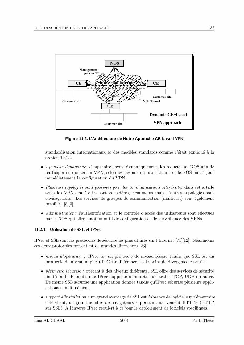
11.2. DESCRIPTION DE NOTRE APPROCHE 137
���������������������������������������������������������������������������������������������������������������������������������������������������������������������������������������������������������������������������������������������������������������������������������������������������������������������������������������������������������������������������������������������������������������������������������������������������������������������������������������������������������������������������������������������������������������������������������������������������������������������������������������������������������������������������������������������������������������������������������������������������������������������������������������������������������
���������������������������������������������������������������������������������������������������������������������������������������������������������������������������������������������������������������������������������������������������������������������������������������������������������������������������������������������������������������������������������������������������������������������������������������������������������������������������������������������������������������������������������������������������������������������������������������������������������������������������������������������������������������������������������������������������������������������������������������������������������������
Dynamic CE−based
VPN approach
policies
CE
Customer site
Customer site
Customer siteVPN Tunnel
NOS
CE
CE
Management
untrusted Internet
Figure 11.2. L’Architecture de Notre Approche CE-based VPN
standardisation internationaux et des modeles standards comme c’etait explique a lasection 10.1.2.
• Approche dynamique: chaque site envoie dynamiquement des requetes au NOS afin departiciper ou quitter un VPN, selon les besoins des utilisateurs, et le NOS met a jourimmediatement la configuration du VPN.
• Plusieurs topologies sont possibles pour les communications site-a-site: dans cet articleseuls les VPNs en etoiles sont consideres, neanmoins mais d’autres topologies sontenvisageables. Les services de groupes de communication (multicast) sont egalementpossibles [5][3].
• Administration: l’authentification et le controle d’acces des utilisateurs sont effectuespar le NOS qui offre aussi un outil de configuration et de surveillance des VPNs.
11.2.1 Utilisation de SSL et IPSec
IPsec et SSL sont les protocoles de securite les plus utilises sur l’Internet [71][12]. Neanmoinsces deux protocoles presentent de grandes differences [23]:
• niveau d’operation : IPsec est un protocole de niveau reseau tandis que SSL est unprotocole de niveau applicatif. Cette difference est le point de divergence essentiel.
• perimetre securise : operant a des niveaux differents, SSL offre des services de securitelimites a TCP tandis que IPsec supporte n’importe quel trafic, TCP, UDP ou autre.De meme SSL securise une application donnee tandis qu’IPsec securise plusieurs appli-cations simultanement.
• support d’installation : un grand avantage de SSL est l’absence de logiciel supplementairecote client, un grand nombre de navigateurs supportant nativement HTTPS (HTTPsur SSL). A l’inverse IPsec requiert a ce jour le deploiement de logiciels specifiques.
Lina AL-CHAAL 2004 Ph.D Thesis
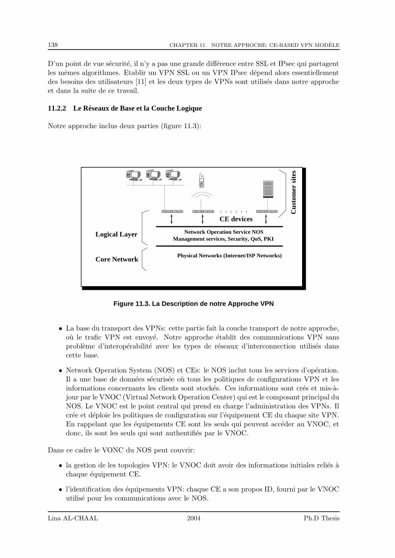
138 CHAPTER 11. NOTRE APPROCHE: CE-BASED VPN MODELE
D’un point de vue securite, il n’y a pas une grande difference entre SSL et IPsec qui partagentles memes algorithmes. Etablir un VPN SSL ou un VPN IPsec depend alors essentiellementdes besoins des utilisateurs [11] et les deux types de VPNs sont utilises dans notre approcheet dans la suite de ce travail.
11.2.2 Le Reseaux de Base et la Couche Logique
Notre approche inclus deux parties (figure 11.3):
Core Network
Network Operation Service NOSManagement services, Security, QoS, PKI
Logical Layer
Cus
tom
er s
ites
Physical Networks (Internet/ISP Networks)
CE devices
��������
��������
������������
Figure 11.3. La Description de notre Approche VPN
• La base du transport des VPNs: cette partie fait la couche transport de notre approche,ou le trafic VPN est envoye. Notre approche etablit des communications VPN sansprobleme d’interoperabilite avec les types de reseaux d’interconnection utilises danscette base.
• Network Operation System (NOS) et CEs: le NOS inclut tous les services d’operation.Il a une base de donnees securisee ou tous les politiques de configurations VPN et lesinformations concernants les clients sont stockes. Ces informations sont cres et mis-a-jour par le VNOC (Virtual Network Operation Center) qui est le composant principal duNOS. Le VNOC est le point central qui prend en charge l’administration des VPNs. Ilcree et deploie les politiques de configuration sur l’equipement CE du chaque site VPN.En rappelant que les equipements CE sont les seuls qui peuvent acceder au VNOC, etdonc, ils sont les seuls qui sont authentifies par le VNOC.
Dans ce cadre le VONC du NOS peut couvrir:
• la gestion de les topologies VPN: le VNOC doit avoir des informations initiales relies achaque equipement CE.
• l’identification des equipements VPN: chaque CE a son propos ID, fourni par le VNOCutilise pour les communications avec le NOS.
Lina AL-CHAAL 2004 Ph.D Thesis
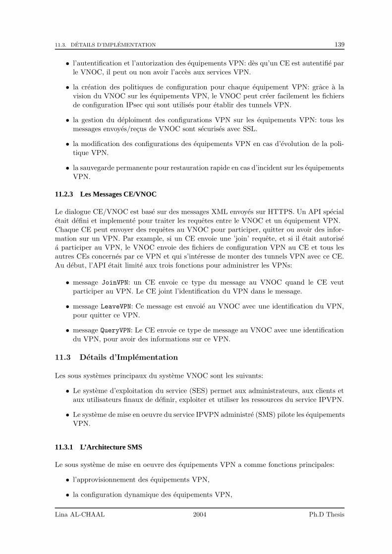
11.3. DETAILS D’IMPLEMENTATION 139
• l’autentification et l’autorization des equipements VPN: des qu’un CE est autentifie parle VNOC, il peut ou non avoir l’acces aux services VPN.
• la creation des politiques de configuration pour chaque equipement VPN: grace a lavision du VNOC sur les equipements VPN, le VNOC peut creer facilement les fichiersde configuration IPsec qui sont utilises pour etablir des tunnels VPN.
• la gestion du deploiment des configurations VPN sur les equipements VPN: tous lesmessages envoyes/recus de VNOC sont securises avec SSL.
• la modification des configurations des equipements VPN en cas d’evolution de la poli-tique VPN.
• la sauvegarde permanente pour restauration rapide en cas d’incident sur les equipementsVPN.
11.2.3 Les Messages CE/VNOC
Le dialogue CE/VNOC est base sur des messages XML envoyes sur HTTPS. Un API specialetait defini et implemente pour traiter les requetes entre le VNOC et un equipement VPN.Chaque CE peut envoyer des requetes au VNOC pour participer, quitter ou avoir des infor-mation sur un VPN. Par example, si un CE envoie une ’join’ requete, et si il etait autorisea participer au VPN, le VNOC envoie des fichiers de configuration VPN au CE et tous lesautres CEs concernes par ce VPN et qui s’interesse de monter des tunnels VPN avec ce CE.Au debut, l’API etait limite aux trois fonctions pour administrer les VPNs:
• message JoinVPN: un CE envoie ce type du message au VNOC quand le CE veutparticiper au VPN. Le CE joint l’identification du VPN dans le message.
• message LeaveVPN: Ce message est envoie au VNOC avec une identification du VPN,pour quitter ce VPN.
• message QueryVPN: Le CE envoie ce type de message au VNOC avec une identificationdu VPN, pour avoir des informations sur ce VPN.
11.3 Details d’Implementation
Les sous systemes principaux du systeme VNOC sont les suivants:
• Le systeme d’exploitation du service (SES) permet aux administrateurs, aux clients etaux utilisateurs finaux de definir, exploiter et utiliser les ressources du service IPVPN.
• Le systeme de mise en oeuvre du service IPVPN administre (SMS) pilote les equipementsVPN.
11.3.1 L’Architecture SMS
Le sous systeme de mise en oeuvre des equipements VPN a comme fonctions principales:
• l’approvisionnement des equipements VPN,
• la configuration dynamique des equipements VPN,
Lina AL-CHAAL 2004 Ph.D Thesis
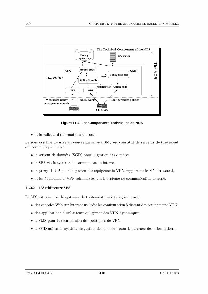
140 CHAPTER 11. NOTRE APPROCHE: CE-BASED VPN MODELE
SMSSES
APIGUI
Configurations policies management console
Web based policy XML events
CE device
The Technical Components of the NOS
CA serverT
he NO
S
The VNOC
Action code
Action code
Policy Handler
Policy HandlerEvent
Notification
Policyrepository
Figure 11.4. Les Composants Techniques de NOS
• et la collecte d’informations d’usage.
Le sous systeme de mise en oeuvre du service SMS est constitue de serveurs de traitementqui communiquent avec:
• le serveur de donnees (SGD) pour la gestion des donnees,
• le SES via le systeme de communication interne,
• le proxy IP-UP pour la gestion des equipements VPN supportant le NAT traversal,
• et les equipements VPN administres via le systeme de communication externe.
11.3.2 L’Architecture SES
Le SES est compose de systemes de traitement qui interagissent avec:
• des consoles Web sur Internet utilisees les configuration a distant des equipements VPN,
• des applications d’utilisateurs qui gerent des VPN dynamiques,
• le SMS pour la transmission des politiques de VPN,
• le SGD qui est le systeme de gestion des donnees, pour le stockage des informations.
Lina AL-CHAAL 2004 Ph.D Thesis
11.3. DETAILS D’IMPLEMENTATION 141
NavigatorHTML JavaScript
Mod−SSL
Mod−jkWeb Server Apache
JSP
Java BeansJava Mail
The Internet
Presentation
Logical application
Navigation
Data managementManagement PoolEntities
JDBCTomcat Server
The Technical Components of the SES
HTTPS
HTTP
Java
Java
Oracle
SMTPOracleSGBD
Figure 11.5. Les Composants de SES
Lina AL-CHAAL 2004 Ph.D Thesis

142 CHAPTER 11. NOTRE APPROCHE: CE-BASED VPN MODELE
Lina AL-CHAAL 2004 Ph.D Thesis
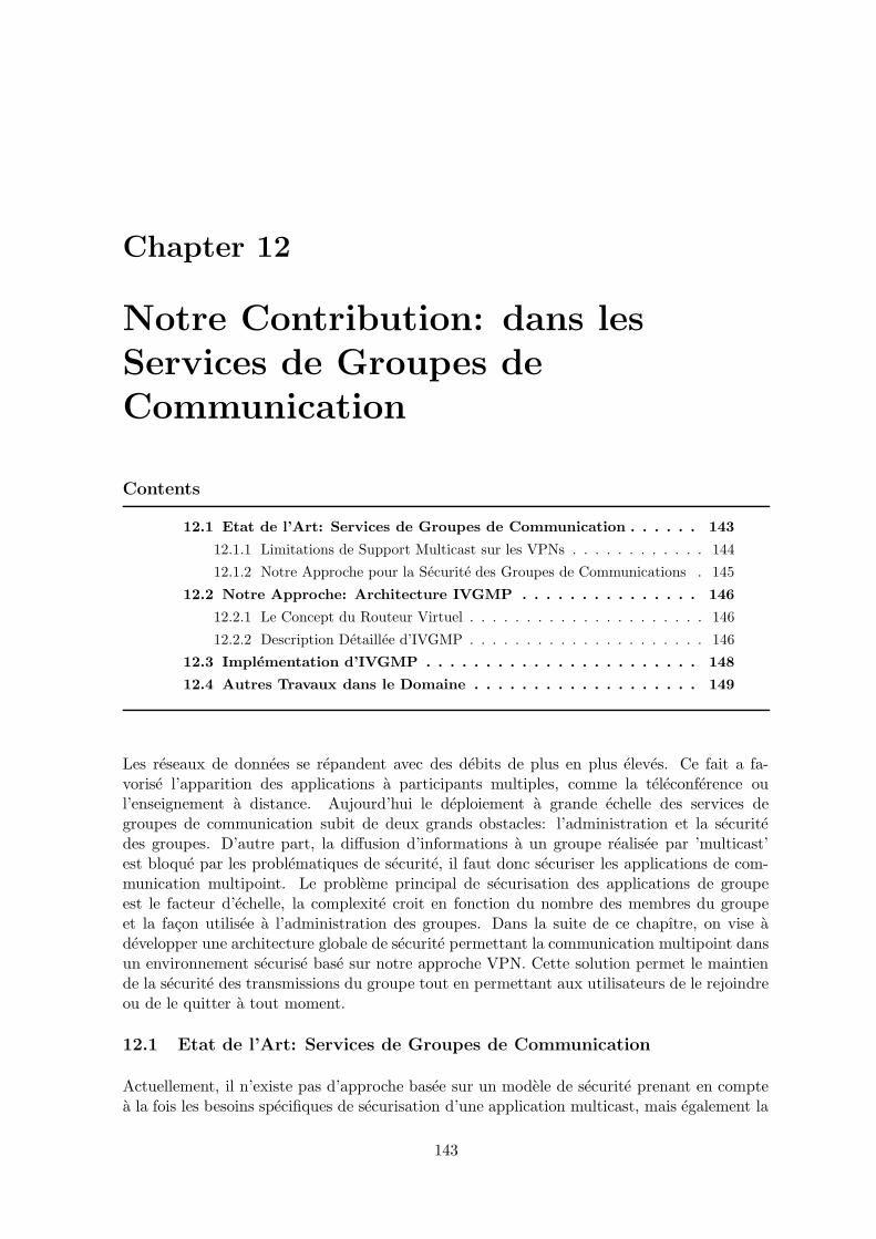
Chapter 12
Notre Contribution: dans lesServices de Groupes deCommunication
Contents
12.1 Etat de l’Art: Services de Groupes de Communication . . . . . . 143
12.1.1 Limitations de Support Multicast sur les VPNs . . . . . . . . . . . . 144
12.1.2 Notre Approche pour la Securite des Groupes de Communications . 145
12.2 Notre Approche: Architecture IVGMP . . . . . . . . . . . . . . . 146
12.2.1 Le Concept du Routeur Virtuel . . . . . . . . . . . . . . . . . . . . . 146
12.2.2 Description Detaillee d’IVGMP . . . . . . . . . . . . . . . . . . . . . 146
12.3 Implementation d’IVGMP . . . . . . . . . . . . . . . . . . . . . . . 148
12.4 Autres Travaux dans le Domaine . . . . . . . . . . . . . . . . . . . 149
Les reseaux de donnees se repandent avec des debits de plus en plus eleves. Ce fait a fa-vorise l’apparition des applications a participants multiples, comme la teleconference oul’enseignement a distance. Aujourd’hui le deploiement a grande echelle des services degroupes de communication subit de deux grands obstacles: l’administration et la securitedes groupes. D’autre part, la diffusion d’informations a un groupe realisee par ’multicast’est bloque par les problematiques de securite, il faut donc securiser les applications de com-munication multipoint. Le probleme principal de securisation des applications de groupeest le facteur d’echelle, la complexite croit en fonction du nombre des membres du groupeet la facon utilisee a l’administration des groupes. Dans la suite de ce chapıtre, on vise adevelopper une architecture globale de securite permettant la communication multipoint dansun environnement securise base sur notre approche VPN. Cette solution permet le maintiende la securite des transmissions du groupe tout en permettant aux utilisateurs de le rejoindreou de le quitter a tout moment.
12.1 Etat de l’Art: Services de Groupes de Communication
Actuellement, il n’existe pas d’approche basee sur un modele de securite prenant en comptea la fois les besoins specifiques de securisation d’une application multicast, mais egalement la
143
144 CHAPTER 12. NOTRE CONTRIBUTION: DANS LES SERVICES DE GROUPES DE COMMUNICATION
connaissance de l’environnement (le reseau, ses services, ses capacites en matiere de securite).Le facteur d’echelle joue aussi sur la complexite et la dynamisite des solutions a apporter.De plus, la securisation des echanges multicast doit rester la plus transparente possible pourl’utilisateur. Et le dysfonctionnement d’un equipement d’un membre de groupe, ne doit nientraıner l’arret du reseau, ni mettre en peril sa securite. La definition et la conception d’unearchitecture et des protocoles associes pour atteindre ces objectifs constituent l’objet de notreapproche.
12.1.1 Limitations de Support Multicast sur les VPNs
On classifie deux domaines importants:
Multicast sur VPNs
Les solutions developees par des fournisseurs PPVPN pour le deploiement du multicast, pour-ront beneificier d’avoir la maıtrise des reseaux d’interconnection pour ouffrir des equipementsVPN capable a gerer du trafic multicast ([70], [75]). La plupart du travail actuel dans cedomaine, est concentre a founir le service multicast pour des reseaux prives d’interconnection,administres par des operateurs ([8], [55]).
Par example, le draft [75], supporte le transport du trafic multicast, est base sur les car-acteristiques suivantes:
• un domaine multicast est un ensemble de tables de routage (VRFs), disponibles surles equipements PE des operateurs et associes aux interfaces qui supportent le traficmulticast. Un tableau VRF peut appartient a un ou plusieurs domaines multicast.
• chaque domaine multicast est associe a une nouvelle adresse multicast, appartienne ala plage d’adressage du reseau operateur.
• le protocole PIM-SM est execute sur chaque routeur PE. Les routeurs PE participentaux differents groupes multicast selon les domaines de multicast ou ils sont attaches.
Cette approche cree une arbre de diffusion multicast pour chaque domaine multicast du reseauoperateur. Le traffic multicast des clients est transmit par le reseau operateur, encapsule dansun paquet en utilisant une adresse destination de groupe multicast. L’encapsultaion est faitedans des tunnels MPLS ou GRE. Par contre, une instance VRF de PIM-SM est executee surchaque routeur PE et qui communique avec un equipement CE et assure l’acheminement dutraffic multicast pour un ou plusieurs domaines multicast.
Pour des raisons de scalabilite, cette approche ne prend pas en consideration si des recepteurssont actuellement presents derrieres les routeurs PE et si ils sont toujours interessants derecevoir du traffic multicast concernant leurs domaines multicast. Dans ce cas la, chaquerouteur PE attache au domaine multicast, va recevoir du traffic multicast destine a ce groupe,meme si il y a aucun recepteur qui s’insteresse a ce traffic au moment de la transmission dutraffic multicast.
Ces approches sont differentes de la notre pour deux raisons principales (1) l’effet que cesapproches sont destinees a l’utilistaion dans des reseaux operateurs [76], pendant que la notreest basee sur la technologie aux extremites (2) ces approaches n’addressent pas le problemed’utiliser IPsec sur PIM.
Lina AL-CHAAL 2004 Ph.D Thesis
12.2. NOTRE APPROCHE: ARCHITECTURE IVGMP 145
Securite du Multicast
L’etat de l’art de la securite multicast garantit l’acces restreint a des donnees diffusees, par leprincipe du chiffrement avec une cle secrete qui est partagee entre les membres du groupe derecepteurs autorises. Cette approche pose un probleme dans le cas de scenarios de distributionde contenus a des groupes dabonnes diffuses sur l’Internet, puisque elle necessite un schemade controle d’acces depend de la fiabilite de chacun des membres du groupe et une methodedu chiffrement pour le trafic multicast ([54], [14]). Les reseaux prives virtuels VPNs basessur le standard IPsec font des bons environements pour la distribution des donnees multicast,mais cela requiert de remplacer le protocole de gestion des cles IKE par un autre protocolequi prend en charge la diffusion d’une cle partagee pour un groupe multicast. Les activites destandardisation du groupe IETF MSEC sont en cours de developpement [13]. Ces activitessont faites pour trouver un replacement du protocole IKE dans les cas des applications ou ona un expediteur pour chaque groupe multicast. Pour conclure, les priorites de notre approchesont differentes de celles des groupes MSEC et PPVPN. Dans les paragraphes suivants ondecrit notre simple approche pour ouffrir un service du deploiment du trafic multicast securise.
12.1.2 Notre Approche pour la Securite des Groupes de Communications
Notre solution est simple et independent de la position de chaque recepteur. Elle consisteraita utiliser notre approche basee sur les reseaux prives virtuels VPNs pour securiser le traficmulticast.
Notre approche concilie le besoin de securite et la gestion d’acces des membres du groupsen impliquant les operations de securite dans le VNOC entre la source et les recepteurs afind’assurer que les donnees arrivent chez les abonnes en etant protegees par des cles. La sourceeffectue un seul chiffrement pour un site VPN quel que soit le nombre de recepteurs dansle site distant. La securite est aussi garantie par IPsec. Ce principe est applique dans unearchitecture a trois plans: la gestion des cles, la gestion des abonnes et la distribution desdonnees.
Le caractere dynamic et centralise de notre approche atteint deux points principaux pourfaire le but de nos besoins:
• Avec un point centralise l’operateur du service VPN peut facilement prendre en chargeles aspects administratives pour la securite d’un groupe de communication. Ceux-ciincluent et n’est pas restreint aux services suivants: le service d’authentification, lecontrole d’acces, l’administration des cles de cryptages, le service du deploiement et leservice de surveillance.
• Les topologies VPNs dans notre approche sont dynamiques, puisque un site VPN peutjoindre ou quitter un VPN a tout moment. Ce qui convient bien a la dynamicite desgroupes multicast.
Pour ses raisons precedentes, notre approche VPN semble a fournir une puisante infras-tructure pour securiser les services de groupes de communication. En particulier, pour lesservices de communication qui sont menaces par des dangers lies aux environements, commel’Internet.
Lina AL-CHAAL 2004 Ph.D Thesis
146 CHAPTER 12. NOTRE CONTRIBUTION: DANS LES SERVICES DE GROUPES DE COMMUNICATION
edgedev.
edgedev.
edgedev.
edgedev.
VPN environment
VNOC
Internet
Laptop
Virtual router in the
device functionnalities
Isolated host with edge
VPN edge devices acting as virtual interfaces
Figure 12.1. Le concept du routeur virtuel.
12.2 Notre Approche: Architecture IVGMP
12.2.1 Le Concept du Routeur Virtuel
Le support VPN dans chaque equipement CE d’un site VPN assure le cheminement dupackets multicast du site local jusqu’aux sites distants qui participent au meme VPN, atravers l’Internet. L’interconnection VPN de plusieurs equipements CE fait le modele d’unseul routeur virtuel (Voir la figure 12.1) avec plusieurs interfaces virtuels, un pour chaqueequipement CE. On introduit le protocole IVGMP dans ce routeur virtuel pour administrer laconfigurations des interfaces virtuels et pour permettre la transmission des packets multicast.IVGMP est un protocole alternatif de ceux du routage multicast, dans un environement IPVPN.
12.2.2 Description Detaillee d’IVGMP
L’Ajout d’un Nouveau Recepteur dans un Site VPN
D’abord, on assume que chaque site VPN est compose par un seul LAN. Le protocole IVGMP,situe sur chaque equipement CE, a l’objet de trouver les nouveaux membres d’un groupemulicast dans le site local attache au CE. Il utilise le mecanisme du IGMP (Internet GroupManagement Protocol) [33] et ses propres messages Query/Report pour decouvrir les nou-veaux clients. Le protocole IVGMP ecoute le trafic IGMP dans le site local pour savoir si ily a des nouveaux clients qui ont l’attention de joindre un groupe multicast, ou pas (Voir lafigure 12.2). Dans le premier cas, IVGMP fait le necessaire pour etablir une nouvelle brancheVPN pour acceder au reste du groupe, si le site local n’appartient pas a ce groupe. IVGMPenvoie une requete JOIN VPN au VNOC pour participer au groupe. Le VNOC recoit larequete, verifie le droit du site pour joindre le groupe et envoie une lettre de confirmation ausite. Le VNOC deploie des nouveaux politiques de configuration sur le site local et sur lesautres sites participes au meme groupe. Si le IVGMP decouvert que aucun client s’interesseau groupe multicast, le IVGMP demonte la branche VPN avec le reste des sites participenta ce groupe, si la branche existe deja.
Lina AL-CHAAL 2004 Ph.D Thesis
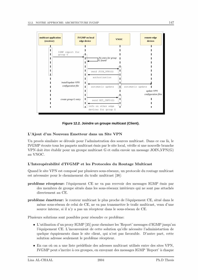
12.2. NOTRE APPROCHE: ARCHITECTURE IVGMP 147
devices for group G
info on other edge
No entry for groupG found
IVGMP on localedge device
VNOCdevices
remote edgemulticast application(receiver)
authorization
send JOIN_VPN(G)
automatic update
send GET_INFO(G)
configuration file
install/update VPN
create group G entry
group GIGMP report for
automatic update
configuration files
update VPN
Figure 12.2. Joindre un groupe multicast (Client).
L’Ajout d’un Nouveau Emetteur dans un Site VPN
Un proces similaire se deroule pour l’adminstration des sources multicast. Dans ce cas la, leIVGMP ecoute tous les paquets multicast emis par le site local, verifie si une nouvelle brancheVPN doit etre etablir pour un groupe multicast G et enfin envoie un message JOIN VPN(G)au VNOC.
L’Interoperabilite d’IVGMP et les Protocoles du Routage Multicast
Quand le site VPN est compose par plusieurs sous-reseaux, un protocole du routage multicastest necessaire pour le cheminement du trafic multicast [38]:
probleme recepteur: l’equipement CE ne va pas recevoir des messages IGMP emis pardes membres de groupe situes dans les sous-reseaux interieurs qui ne sont pas attachesdirectement au CE.
probleme emetteur: le routeur multicast le plus proche de l’equipement CE, situe dans lememe sous-reseau de celui de CE, ne va pas transmettre le trafic multicast, venu d’unesource interne, si il n’y a pas un recepteur dans le sous-reseau de CE.
Plusieurs solutions sont possibles pour resoudre ce probleme:
• L’utilisation d’un proxy IGMP [35] pour cheminer les ’Report’ messages d’IGMP jusqu’aul’equipement CE. L’inconvenient de cette solution qu’elle necessite l’administartion dequelque equpiements dans le site client, qui n’est pas favorable. D’autre part, cettesolution adresse seulement le probleme recepteur.
• En cas ou on a une liste predefinie des adresses multicast utilises entre des sites VPN,IVGMP peut s’incrire a ces groupes, en envoyant des messages IGMP ’Report’ a chaque
Lina AL-CHAAL 2004 Ph.D Thesis

148 CHAPTER 12. NOTRE CONTRIBUTION: DANS LES SERVICES DE GROUPES DE COMMUNICATION
fois qu’un routeur multicast envoie un IGMP ’Query’. Dans ce cas, le trafic multicast en-voye par des sources internes, sera transmettre jusqu’a l’equipement CE. L’inconvenientde cette solution est d’avoir plein du traffic de signalement d’IGMP.
• Une autre solution est basee sur des applications dediees, utilisees par les clients et quiinforment l’IVGMP de la presence d’une source multicast ou des nouveaux clients pourdes groupes multicast. L’IVGMP peut donc contacter le VNOC et inscrire le site localau groupe multicast. Cette solution met un peu de charge sur les clients, mais evitedes modifications dans le site local.
12.3 Implementation d’IVGMP
link−level driverExternal Interface
IP Protocol
UDP
Sock DGram
IPSec
Sock Raw
BPF Packet Filter
link−level driverInternal Interface
mcast/IGMP pkts sent toor recv’ed from local site
IPSec packets sent to orrecv’ed from VPN sites
Kernel space
User−process
IVGMP
Figure 12.3. Vue architecturale du traitement des paquets IVGMP.
On a implemente le protocole IVGMP dans des equipements PC/Linux (voir la figure 12.3).On a utilise une version modifie de FreeS/Wan IPsec, l’implementation IKE pour OpenBSD[42], et les utils d’administration de Netcelo (le VNOC) [63].Les communications IVGMP-VNOC utilisees pour maintenir la liste des VPNs pour le fonc-tionnement du service multicast, sont basees sur le protocole SOAP ’Simple Object Applica-tion Protocol’ des services web. Ceci offre egalement lavantage dune grande souplesse pourfaire face aux problemes actuels d’interoperabilite relatifs aux pare-feux/ proxies 6.Voici les demarches du traitements des paquets multicast sur chaque equipement CE: Unpaquet multicast, venu d’une source active dans le site local, est intercepte par la filtreBPP [48] tournee sur l’equipement CE et envoye au demon IVGMP. IVGMP cherche uneentree VPN qui correspond a l’addresse multicast de destination pour verifier si le paquetdoit etre transmis aux autres sites distants. Si une entree est trouvee, une copie du paquet
Lina AL-CHAAL 2004 Ph.D Thesis
12.4. AUTRES TRAVAUX DANS LE DOMAINE 149
sera encapsulee dans un segment UDP/IP pour chaque sites distants et puis delivree auIPsec qu’il l’envoie sur le tunnel convenable. Dans l’autre sens, les paquets recus par lessites distants sont traites par IPsec, IP, UDP et puis IVGMP. Ce dernier injecte l’orginal dupaquet multicast sur le site local a travers les raw sockets.
12.4 Autres Travaux dans le Domaine
L’approche discutee dans ce chapıtre, adopte plusieurs technologies comme l’utilisation desreseaux VPNs sur IP, le service web (SOAP) et les reseaux programmables pour offrir une so-lution simple et flexible pour securiser les services de groupes de communication sur l’Internet[5]. En meme temps, notre approche a des points de similarites avec l’approche CM ’Central-ized Multicast’ [51]. Dans l’approche CM, le trafic des donnees est separe de celui du controleet la partie du controle est centralisee dans plusieurs noeuds distribues. La difference majureentre cette approche et la notre, est la securite, puisque le CM n’addresse pas la securite dutrafic des donnees.
Lina AL-CHAAL 2004 Ph.D Thesis

150 CHAPTER 12. NOTRE CONTRIBUTION: DANS LES SERVICES DE GROUPES DE COMMUNICATION
Lina AL-CHAAL 2004 Ph.D Thesis
Chapter 13
Notre Contribution: dans lesServices Web
Contents
13.1 Etat de l’Art: Services Web . . . . . . . . . . . . . . . . . . . . . . 151
13.1.1 Architecture d’un Service Web . . . . . . . . . . . . . . . . . . . . . 151
13.1.2 Evolution des Services Web et Challenges Associes . . . . . . . . . . 152
13.2 Notre Approche: Services Web VPN . . . . . . . . . . . . . . . . 154
13.2.1 Architecture . . . . . . . . . . . . . . . . . . . . . . . . . . . . . . . 154
13.2.2 Les Deux Phase d’Etablissement d’un Service Web VPN . . . . . . . 155
13.3 Implementation et Evaluation des Services Web VPN . . . . . . 156
13.4 Autres Travaux dans le Domaine . . . . . . . . . . . . . . . . . . . 158
Les services web prennent leurs origines dans l’informatique distribuee et dans l’avenementdu Web (en particulier le commerce electronique sur l’Internet). Ils offrent des services appli-catifs publies, localises et executes sur l’Internet, et accessibles via des protocoles standardisesdu web par des entites distantes (applications ou utilisateurs finaux) [59]. L’adoption de stan-dards comme XML, SOAP, WSDL et UDDI a largement contribue au succes car cela resout leprobleme d’interoperabilite entre les differentes plates-formes [64]. Neanmoins des obstaclesmajeurs a l’adoption des services web restent, a savoir la securite et surtout l’administrationdynamique des services web. Dans ce chapitre, on va discuter les differents obstacles desservices web actuels, et nous proposons un modele hybride qui fusionne les services VPNsdans un architecture des services web. La suite de ce chapiter est organise ainsi : la sec-tion 13.1 discute les problemes d’administration et de securisation des services web; nousintroduisons notre proposition au sein de la section 13.2, puis rendons compte d’une premiereevaluation du systeme en section 13.3. Finalement nous presentons des travaux associes puisnous concluons.
13.1 Etat de l’Art: Services Web
13.1.1 Architecture d’un Service Web
Un service web typique comporte trois elements (figure 13.1):
151
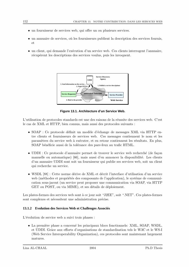
152 CHAPTER 13. NOTRE CONTRIBUTION: DANS LES SERVICES WEB
• un fournisseur de services web, qui offre un ou plusieurs services.
• un annuaire de services, ou les fournisseurs publient la description des services fournis,et
• un client, qui demande l’execution d’un service web. Ces clients interrogent l’annuaire,recuperent les descriptions des services voulus, puis les invoquent.
����������������������������������������������������������������������������������������������������������������������������������������������������������������������������������������������������������������������������������������������������������������������������������������������������������������������������������������������������������������������������������������������������������������������������������������������������������������������������������������������������������������������������������������������������������������������������������������������������������������������������������������������������������������������������������������������������������������������������������������������������������������������������������������������������������������������������������������������
��������������������������������������������������������������������������������������������������������������������������������������������������������������������������������������������������������������������������������������������������������������������������������������������������������������������������������������������������������������������������������������������������������������������������������������������������������������������������������������������������������������������������������������������������������������������������������������������������������������������������������������������������������������������������������������������������������������������������������������������������������������������������������������������������
UDDI Agency
Service Requester
1. Publish a service descriptions
untrusted Internet
4. Bind to the provider
2. Find a service3. Send information on the service
Service Discovery
Web Service
Service Provider
Figure 13.1. Architecture d’un Service Web.
L’utilisation de protocoles standards est une des raisons de la reussite des services web. C’estle cas de XML et HTTP, bien connus, mais aussi des protocoles suivants :
• SOAP : Ce protocole definit un modele d’echange de messages XML via HTTP en-tre clients et fournisseurs de services web. Ces messages contiennent le nom et lesparametres du service web a executer, et en retour contiennent les resultats. En plus,SOAP beneficie aussi de la tolerance des pare-feux au trafic HTML.
• UDDI : Ce protocole d’annuaire permet de trouver le service web recherche (de faconmanuelle ou automatique) [66], mais aussi d’en annoncer la disponibilite. Les clientsd’un annuaire UDDI sont soit un fournisseur qui publie ses services web, soit un clientqui recherche un service.
• WSDL [88] : Cette norme derive de XML et decrit l’interface d’utilisation d’un serviceweb (methodes et proprietes des composants de l’application), le systeme de communi-cation sous-jacent (un service peut proposer une communication via SOAP, via HTTPGET ou POST, ou via MIME), et ses details de deploiement.
Les plates-formes des services web sont a ce jour soit “J2EE”, soit “.NET”. Ces plates-formessont complexes et necessitent une administration precise.
13.1.2 Evolution des Services Web et Challenges Associes
L’evolution de service web a suivi trois phases :
• La premiere phase a concerne les principaux blocs fonctionnels: XML, SOAP, WSDL,et UDDI. Grace aux efforts d’organisations de standardisation tels le W3C et le WS-I(Web Service Interoperability Organization), ces protocoles sont maintenant largementmatures.
Lina AL-CHAAL 2004 Ph.D Thesis
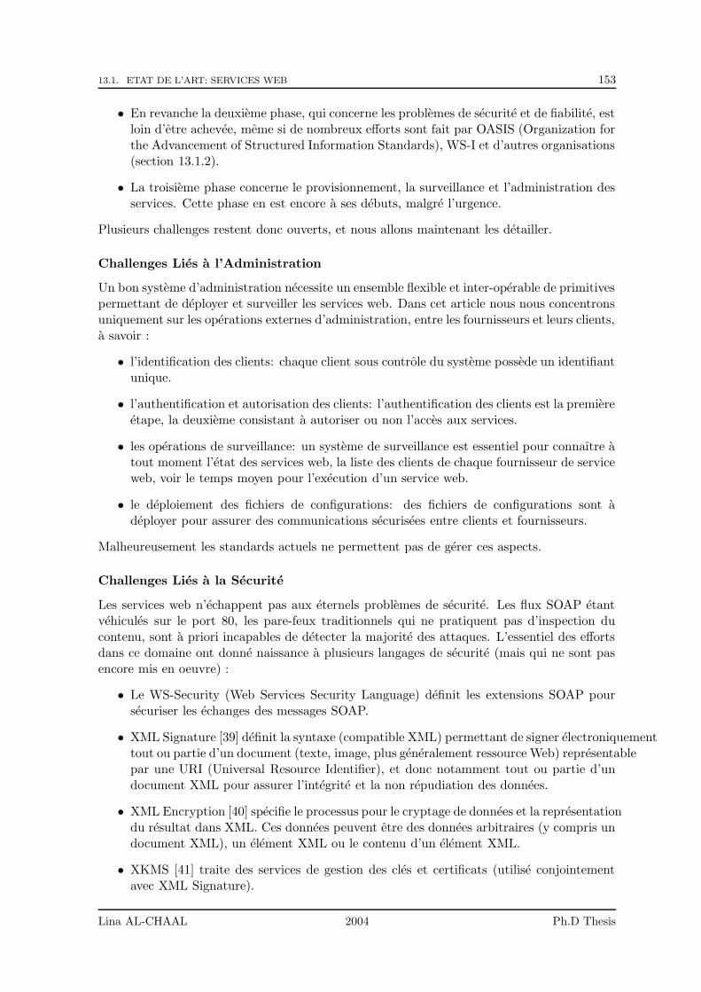
13.1. ETAT DE L’ART: SERVICES WEB 153
• En revanche la deuxieme phase, qui concerne les problemes de securite et de fiabilite, estloin d’etre achevee, meme si de nombreux efforts sont fait par OASIS (Organization forthe Advancement of Structured Information Standards), WS-I et d’autres organisations(section 13.1.2).
• La troisieme phase concerne le provisionnement, la surveillance et l’administration desservices. Cette phase en est encore a ses debuts, malgre l’urgence.
Plusieurs challenges restent donc ouverts, et nous allons maintenant les detailler.
Challenges Lies a l’Administration
Un bon systeme d’administration necessite un ensemble flexible et inter-operable de primitivespermettant de deployer et surveiller les services web. Dans cet article nous nous concentronsuniquement sur les operations externes d’administration, entre les fournisseurs et leurs clients,a savoir :
• l’identification des clients: chaque client sous controle du systeme possede un identifiantunique.
• l’authentification et autorisation des clients: l’authentification des clients est la premiereetape, la deuxieme consistant a autoriser ou non l’acces aux services.
• les operations de surveillance: un systeme de surveillance est essentiel pour connaıtre atout moment l’etat des services web, la liste des clients de chaque fournisseur de serviceweb, voir le temps moyen pour l’execution d’un service web.
• le deploiement des fichiers de configurations: des fichiers de configurations sont adeployer pour assurer des communications securisees entre clients et fournisseurs.
Malheureusement les standards actuels ne permettent pas de gerer ces aspects.
Challenges Lies a la Securite
Les services web n’echappent pas aux eternels problemes de securite. Les flux SOAP etantvehicules sur le port 80, les pare-feux traditionnels qui ne pratiquent pas d’inspection ducontenu, sont a priori incapables de detecter la majorite des attaques. L’essentiel des effortsdans ce domaine ont donne naissance a plusieurs langages de securite (mais qui ne sont pasencore mis en oeuvre) :
• Le WS-Security (Web Services Security Language) definit les extensions SOAP poursecuriser les echanges des messages SOAP.
• XML Signature [39] definit la syntaxe (compatible XML) permettant de signer electroniquementtout ou partie d’un document (texte, image, plus generalement ressource Web) representablepar une URI (Universal Resource Identifier), et donc notamment tout ou partie d’undocument XML pour assurer l’integrite et la non repudiation des donnees.
• XML Encryption [40] specifie le processus pour le cryptage de donnees et la representationdu resultat dans XML. Ces donnees peuvent etre des donnees arbitraires (y compris undocument XML), un element XML ou le contenu d’un element XML.
• XKMS [41] traite des services de gestion des cles et certificats (utilise conjointementavec XML Signature).
Lina AL-CHAAL 2004 Ph.D Thesis

154 CHAPTER 13. NOTRE CONTRIBUTION: DANS LES SERVICES WEB
• XACML [68] specifie les politiques utilisees pour acceder aux documents XML selonleur contenu, le sujet et l’action (lire, ecrire, creer, effacer).
• SAML [67] est un dialecte XML pour exprimer des informations d’authentification surdes systemes securises et pour definir des droits utilisateurs generiques.
• SPML [69] vise a normaliser le mode d’invocation et d’administration d’une plate-formede provisionnement.
Tous ces standards ont pour but de securiser les donnees XML, mais ils ne visent pas asecuriser ni le service web lui-meme, ni le trafic du service web. Aussi le trafic SOAP doit-il etre transporte sur HTTP/SSL ou TLS (Transport Layer Security) pour une securite debout-en-bout [28]. IPSec [49] permet lui aussi de securiser les messages web dans un serviceweb, avec une approche ici point-a-point.
Mais aucune de ces solutions n’offre a notre avis suffisamment de souplesse pour permettred’administrer les politiques de securite entre les differents elements du service web, tout enevitant les conflits d’interoperabilite. De plus la solution doit etre dynamique et permettrede generer les politiques de configurations sans intervention humaine.
13.2 Notre Approche: Services Web VPN
13.2.1 Architecture
Notre architecture est basee sur l’integration des services VPN et services web. On yretrouve en particulier tous les composants d’un service web ordinaire. Le MOP, le cen-tre d’administration centralise, prend en charge les fonctions d’administration des servicesweb. Cependant le MOP n’intervient pas dans les processus des services web eux-memes. LeMOP contient deux elements :
• un annuaire UDDI, qui contient les descriptions des services web, et
• un VNOC qui assure les operations d’administration.
Notre architecture cree un service web specifique aux operations d’administration. On peutdonc distinguer:
• les services web ’commerciaux’ (ou business web services), fournis par les fournisseursdes services web a leurs clients, et
• le service web d’administration (ou management web service), fourni par le MOP achaque element des services web commerciaux.
Il s’agit donc d’une application recursive (!) de la notion de service web. Nous trouveronsdonc a la fois un fichier WSDL pour decrire les services d’administration fournis par l’interfaced’administration, et un fichier WSDL pour decrire les services web commerciaux. A chaquefois SOAP est utilise pour les echanges de messages.
Afin de simplifier les operations administratives liees aux services web commerciaux, ainsi queles problemes de securite, le service web d’administration adopte la technologie VPN. Ainsi leMOP cree dynamiquement un VPN pour chaque service web commercial, chaque VPN ayantune topologie en etoile et contenant:
• un fournisseur de services web: ce fournisseur est le centre du VPN,
Lina AL-CHAAL 2004 Ph.D Thesis
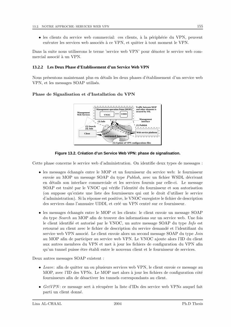
13.2. NOTRE APPROCHE: SERVICES WEB VPN 155
• les clients du service web commercial: ces clients, a la peripherie du VPN, peuventexecuter les services web associes a ce VPN, et quitter a tout moment le VPN.
Dans la suite nous utiliserons le terme ’service web VPN’ pour denoter le service web com-mercial associe a un VPN.
13.2.2 Les Deux Phase d’Etablissement d’un Service Web VPN
Nous presentons maintenant plus en details les deux phases d’etablissement d’un service webVPN, et les messages SOAP utilises.
Phase de Signalisation et d’Installation du VPN
��������������������������������������������������������������������������������������������������������������������������������������������������������������������������������������������������������������������������������������������������������������������������������������������������������������������������������������������������������������������������������������������������������������������������������������������������������������������������������������������������������������������������������������������������������������������������������������������������������������������������������������������������������������������������������������������������������������������������������������������������������������������
��������������������������������������������������������������������������������������������������������������������������������������������������������������������������������������������������������������������������������������������������������������������������������������������������������������������������������������������������������������������������������������������������������������������������������������������������������������������������������������������������������������������������������������������������������������������������������������������������������������������������������������������������������������������������������������������������������������������������������������������������������������������
Managementinterface
UDDIManagementWeb Services
Traffic between MOPand other elements issecured by SSL
untrusted InternetWeb service platformClient
Management operation Point (MOP)
VNOC
(2) Search (1) Publish
(3) Info
(4) Join
(5) Update of VPN configurations files
Figure 13.2. Creation d’un Service Web VPN: phase de signalisation.
Cette phase concerne le service web d’administration. On identifie deux types de messages :
• les messages echanges entre le MOP et un fournisseur du service web: le fournisseurenvoie au MOP un message SOAP du type Publish, avec un fichier WSDL decrivanten details son interface commerciale et les services fournis par celle-ci. Le messageSOAP est traite par le VNOC qui verifie l’identite du fournisseur et son autorisation(on suppose qu’existe une liste des fournisseurs qui ont le droit d’utiliser le serviced’administration). Si la reponse est positive, le VNOC enregistre le fichier de descriptiondes services dans l’annuaire UDDI, et cree un VPN centre sur ce fournisseur.
• les messages echanges entre le MOP et les clients: le client envoie un message SOAPdu type Search au MOP afin de trouver des informations sur un service web. Une foisle client identifie et autorise par le VNOC, un autre message SOAP du type Info estretourne au client avec le fichier de description du service demande et l’identifiant duservice web VPN associe. Le client envoie alors un second message SOAP du type Joinau MOP afin de participer au service web VPN. Le VNOC ajoute alors l’ID du clientaux autres membres du VPN et met a jour les fichiers de configuration du VPN afinqu’un tunnel puisse etre etabli entre le nouveau client et le fournisseur de services.
Deux autres messages SOAP existent :
• Leave: afin de quitter un ou plusieurs services web VPN, le client envoie ce message auMOP, avec l’ID des VPNs. Le MOP met alors a jour les fichiers de configuration cotefournisseurs afin de desactiver les tunnels correspondants au client.
• GetVPN : ce message sert a recuperer la liste d’IDs des service web VPNs auquel faitparti un client donne.
Lina AL-CHAAL 2004 Ph.D Thesis
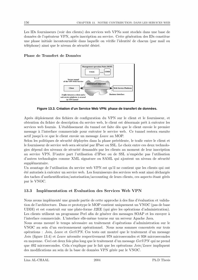
156 CHAPTER 13. NOTRE CONTRIBUTION: DANS LES SERVICES WEB
Les IDs fournisseurs (voir des clients) des services web VPNs sont stockes dans une base dedonnees de l’operateur VPN, apres inscription au service. Cette generation des IDs constitueune phase initiale incontournable dans laquelle on verifie l’identite de chacun (par mail outelephone) ainsi que le niveau de securite desire.
Phase de Transfert de Donnees
����������������������������������������������������������������������������������������������������������������������������������������������������������������������������������������������������������������������������������������������������������������������������������������������������������������������������������������������������������������������������������������������������������������������������������������������������������������������������������������������������������������������������������������������������������������������������������������������������������������������������������������������������������������������������������������������������������������������������������������������������������������������������������������������������������������������������������������������
����������������������������������������������������������������������������������������������������������������������������������������������������������������������������������������������������������������������������������������������������������������������������������������������������������������������������������������������������������������������������������������������������������������������������������������������������������������������������������������������������������������������������������������������������������������������������������������������������������������������������������������������������������������������������������������������������������������������������������������������������������������������������������������������������������������������������������������������Secure tunnel
of the VPN Web Service
UDDI
web service platform, is securedby VPN tunnel
Traffic between a client and a
untrusted Internet
Management operation Point (MOP)
VNOC
Web Service Platform
Business Interface
Client
Figure 13.3. Creation d’un Service Web VPN: phase de transfert de donnees.
Apres deploiement des fichiers de configuration du VPN sur le client et le fournisseur, etobtention du fichier de description du service web, le client est desormais pret a executer lesservices web fournis. L’etablissement du tunnel est faite des que le client envoie le premiermessage a l’interface commerciale pour executer le service web. Ce tunnel restera ensuiteactif jusqu’a ce que le client envoie un message Leave au MOP.
Selon les politiques de securite deployees dans la phase precedente, le trafic entre le client etle fournisseur de service web sera securise par IPsec ou SSL. Le choix entre ces deux technolo-gies depend des niveaux de securite demandes par les clients au moment de leur inscriptionau service VPN. D’autre part l’utilisation d’IPsec ou de SSL n’empeche pas l’utilisationd’autres technologies comme XML signature ou SAML qui ajoutent un niveau de securitesupplementaire.
Un avantage de l’utilisation du service web VPN est qu’il ne contient que les clients qui ontete autorises a executer un service web. Les fournisseurs des services web sont ainsi dechargesdes taches d’authentification/autorisation/accounting de leurs clients, ces aspects etant gerespar le VNOC.
13.3 Implementation et Evaluation des Services Web VPN
Nous avons implemente une grande partie de cette approche a des fins d’evaluation et valida-tion de l’architecture. Dans ce prototype le MOP contient uniquement un VNOC (pas de baseUDDI) et est construit sur une plate-forme J2EE (qui gere les operations d’administration).Les clients utilisent un programme Perl afin de generer des messages SOAP et les envoyer al’interface commerciale. L’interface elle-meme tourne sur un serveur Apache Java.
Nous avons mesure le temps necessaire au traitement d’operations d’administration sur leVNOC au sein d’un environnement operationnel. Nous nous sommes concentres sur troisoperations : Join, Leave et GetVPN. Ces tests ont montre que le traitement d’un messageJoin (figure 13.4) et Leave necessite respectivement 978 microsecondes et 938 microsecondesen moyenne. Ceci est deux fois plus long que le traitement d’un message GetVPN qui ne prendque 492 microsecondes. Cela s’explique par le fait que les operations Join/Leave impliquentdes modifications au sein de la base de donnees VPN geree par le VNOC.
Lina AL-CHAAL 2004 Ph.D Thesis
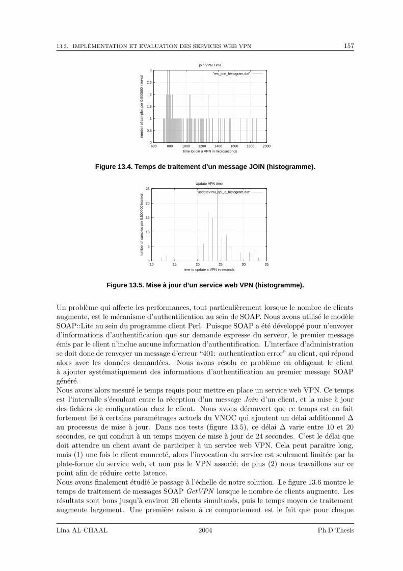
13.3. IMPLEMENTATION ET EVALUATION DES SERVICES WEB VPN 157
0
0.5
1
1.5
2
2.5
3
600 800 1000 1200 1400 1600 1800 2000nu
mbe
r of
sam
ples
per
0.5
0000
0 in
terv
al
time to join a VPN in microseconds
join VPN Time
"res_join_histogram.dat"
Figure 13.4. Temps de traitement d’un message JOIN (histogramme).
0
5
10
15
20
25
10 15 20 25 30 35
num
ber
of s
ampl
es p
er 0
.500
000
inte
rval
time to update a VPN in seconds
Update VPN time
"updateVPN_api_2_histogram.dat"
Figure 13.5. Mise a jour d’un service web VPN (histogramme).
Un probleme qui affecte les performances, tout particulierement lorsque le nombre de clientsaugmente, est le mecanisme d’authentification au sein de SOAP. Nous avons utilise le modeleSOAP::Lite au sein du programme client Perl. Puisque SOAP a ete developpe pour n’envoyerd’informations d’authentification que sur demande expresse du serveur, le premier messageemis par le client n’inclue aucune information d’authentification. L’interface d’administrationse doit donc de renvoyer un message d’erreur “401: authentication error” au client, qui repondalors avec les donnees demandees. Nous avons resolu ce probleme en obligeant le clienta ajouter systematiquement des informations d’authentification au premier message SOAPgenere.Nous avons alors mesure le temps requis pour mettre en place un service web VPN. Ce tempsest l’intervalle s’ecoulant entre la reception d’un message Join d’un client, et la mise a jourdes fichiers de configuration chez le client. Nous avons decouvert que ce temps est en faitfortement lie a certains parametrages actuels du VNOC qui ajoutent un delai additionnel ∆au processus de mise a jour. Dans nos tests (figure 13.5), ce delai ∆ varie entre 10 et 20secondes, ce qui conduit a un temps moyen de mise a jour de 24 secondes. C’est le delai quedoit attendre un client avant de participer a un service web VPN. Cela peut paraıtre long,mais (1) une fois le client connecte, alors l’invocation du service est seulement limitee par laplate-forme du service web, et non pas le VPN associe; de plus (2) nous travaillons sur cepoint afin de reduire cette latence.Nous avons finalement etudie le passage a l’echelle de notre solution. Le figure 13.6 montre letemps de traitement de messages SOAP GetVPN lorsque le nombre de clients augmente. Lesresultats sont bons jusqu’a environ 20 clients simultanes, puis le temps moyen de traitementaugmente largement. Une premiere raison a ce comportement est le fait que pour chaque
Lina AL-CHAAL 2004 Ph.D Thesis
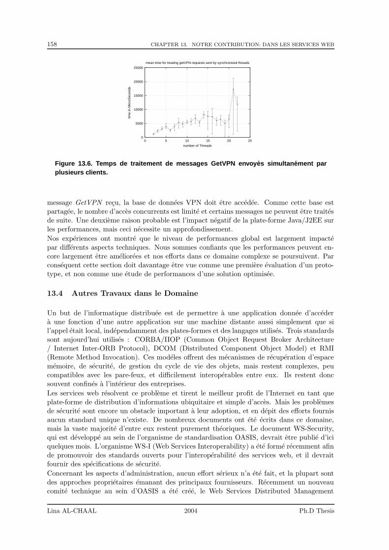
158 CHAPTER 13. NOTRE CONTRIBUTION: DANS LES SERVICES WEB
0
5000
10000
15000
20000
25000
0 5 10 15 20 25
time
in M
icro
Sec
onds
number of Threads
mean time for treating getVPN requests sent by synchronized threads
Figure 13.6. Temps de traitement de messages GetVPN envoyes simultanement parplusieurs clients.
message GetVPN recu, la base de donnees VPN doit etre accedee. Comme cette base estpartagee, le nombre d’acces concurrents est limite et certains messages ne peuvent etre traitesde suite. Une deuxieme raison probable est l’impact negatif de la plate-forme Java/J2EE surles performances, mais ceci necessite un approfondissement.
Nos experiences ont montre que le niveau de performances global est largement impactepar differents aspects techniques. Nous sommes confiants que les performances peuvent en-core largement etre ameliorees et nos efforts dans ce domaine complexe se poursuivent. Parconsequent cette section doit davantage etre vue comme une premiere evaluation d’un proto-type, et non comme une etude de performances d’une solution optimisee.
13.4 Autres Travaux dans le Domaine
Un but de l’informatique distribuee est de permettre a une application donnee d’accedera une fonction d’une autre application sur une machine distante aussi simplement que sil’appel etait local, independamment des plates-formes et des langages utilises. Trois standardssont aujourd’hui utilises : CORBA/IIOP (Common Object Request Broker Architecture/ Internet Inter-ORB Protocol), DCOM (Distributed Component Object Model) et RMI(Remote Method Invocation). Ces modeles offrent des mecanismes de recuperation d’espacememoire, de securite, de gestion du cycle de vie des objets, mais restent complexes, peucompatibles avec les pare-feux, et difficilement interoperables entre eux. Ils restent doncsouvent confines a l’interieur des entreprises.
Les services web resolvent ce probleme et tirent le meilleur profit de l’Internet en tant queplate-forme de distribution d’informations ubiquitaire et simple d’acces. Mais les problemesde securite sont encore un obstacle important a leur adoption, et en depit des efforts fournisaucun standard unique n’existe. De nombreux documents ont ete ecrits dans ce domaine,mais la vaste majorite d’entre eux restent purement theoriques. Le document WS-Security,qui est developpe au sein de l’organisme de standardisation OASIS, devrait etre publie d’iciquelques mois. L’organisme WS-I (Web Services Interoperability) a ete forme recemment afinde promouvoir des standards ouverts pour l’interoperabilite des services web, et il devraitfournir des specifications de securite.
Concernant les aspects d’administration, aucun effort serieux n’a ete fait, et la plupart sontdes approches proprietaires emanant des principaux fournisseurs. Recemment un nouveaucomite technique au sein d’OASIS a ete cree, le Web Services Distributed Management
Lina AL-CHAAL 2004 Ph.D Thesis
13.4. AUTRES TRAVAUX DANS LE DOMAINE 159
(WSDM) Technical Committe, afin de faire le lien entre OASIS et d’autres organismes destandardisation tels le W3C Web Services Architecture Working Group et le DistributedManagement Task Force (DMTF). Ceci inclue l’utilisation des technologies service web afind’administrer des ressources distribuees. La premiere specification Web Services DistributedManagement (WSDM) V1.0 est attendue debut 2004.Outre ces organismes, plusieurs compagnies telles Microsoft, Actionl, Amberpoint, ont dors etdeja compris l’urgence des besoins en matiere de solutions d’administration. Ainsi Microsoftdoit livrer sa nouvelle solution d’administration pour .Net, Microsoft Operations ManagerMOM 2004, en ete 2004.Enfin les precedentes sections ayant dors et deja discute avec force de details plusieurs travauxlies a la securite des services web, nous ne les reprendrons pas ici.
Lina AL-CHAAL 2004 Ph.D Thesis

160 CHAPTER 13. NOTRE CONTRIBUTION: DANS LES SERVICES WEB
Lina AL-CHAAL 2004 Ph.D Thesis
Bibliography
[1] Cisco Secure VPN Client Solutions Guide, 2002. Cisco Systems Inc., Number: OL-0259-02.
[2] Guidelines on IPVPN Deployment: models, architecture and technologies, April 2002.Eurescom Project Report.
[3] L. Alchaal, V. Roca, A. El-Sayed, and M. Habert. A vprn solution for fully secure andefficient group communications. July 2003. 8th IEEE Symposium on Computers andCommunications (ISCC’03), Kemer - Antalya, Turkey.
[4] L. Alchaal, V. Roca, A. El-Sayed, and M. Habert. A VPRN Solution for Fully Secure andEfficient Group Communications. INRIA, Rhone Alpes, April 2003. Research Reportnumber RR-4799.
[5] L. Alchaal, V. Roca, and M. Habert. Offering a multicast delivery service in a pro-grammable secure ip vpn environment. October 2002. Fourth International Workshopon Networked Group Communication (NGC’02), Boston, USA.
[6] L. Alchaal, V. Roca, and M. Habert. De l’utilisation des vpns pour l’administration etla securite des services web. June 2004. 3eme Conference sur la Securite et ArchitecturesReseaux - SAR 2004, La Londe, Cote d’Azur, France.
[7] L. Alchaal, V. Roca, and M. Habert. Managing and securing web services with vpns.July 2004. the second IEEE International Conference on Web Services - ICWS 2004,San Diego, California, USA.
[8] K. C. Almeroth. The evolution of multicast: From the mbone to interdomain multicastto internet2 deployment. January 2000. IEEE Network.
[9] D. G. Andersen, H. Balakrishnan, F. Kaashoek, and R. Morris. Resilient overlay net-works. October 2001. Proc. 18th ACM SOSP, Banff, Canada.
[10] L. Andersson and T. Madsen. PPVPN terminology. PPVPN Working Group, September2003. draft-andersson-ppvpn-terminology-04.txt, work in progress.
[11] Array Networks Inc. SSL VPN vs IPSec VPN, January 2003. white paper.
[12] J. Barrett. A Response to the Feature on IPv6 vs SSL. Root Prompt Org., June 2000.http://rootprompt.org.
[13] M. Baugher, R. Canetti, L. Dondeti, and F. Lindholm. MSEC Group Key ManagementArchitecture, June 2004. Work in Progress, <draft-ietf-msec-gkmarch-08.txt>.
161
162 BIBLIOGRAPHY
[14] M. Baughter, R. Canetti, T. Hardjono, and B. Weis. IP Multicast issues with IPsec,June 2003. work in progress, <draft-ietf-msec-ipsec-multicast-issues-01.txt>.
[15] U. Blumenthal and B. Wijnen. User-based security model (usm) for version 3 of the sim-ple network management protocol (snmpv3). April 1999. IETF Request for Comments,RFC 2574.
[16] D. Box, D. Ehnebuske, G. Kakivaya, A. Layman, N. Mendelsohn, H. F. Nielsen,S. Thatte, and D. Winer. Simple Object Access Protocol (SOAP) 1.1, May 2000. W3CNote. http://www.w3.org/TR/SOAP/.
[17] I. Brown, J. Crowcroft, M. Handley, and B. Cain. Internet multicast tomorrow. Decem-ber 2002. The Internet Protocol Journal (IPJ), vol 5 no 4.
[18] M. Burner and R. Stadler. Virtual active networks- safe and flexible environments forcustomer-managed services. October 1999. Tenth IFIP/IEEE International Workshopon Distributed Systems Operations and Management (DSOM’99), Switzerland.
[19] K. Calvert. Architectural Framework for Active Networks, July 1999. Active Networksworking group.
[20] R. Canetti, P.C. Cheng, D. Pendarakis, J. Rao, P. Rohatgi, and D. Saha. An IPSec-basedHost Architecture for Secure Internet Multicast, February 2000. Network and DistributedSystem Security Symposium (NDSS00), San Diego, USA.
[21] M. Carugi and D. McDysan. Service requirements for Layer 3 Virtual Private Net-works. L3VPN Working Group, July 2004. draft-ietf-l3vpn-requirements-02.txt, work inprogress.
[22] B. Chapman and E. Zwicky. Building Internet Firewalls. O’Reilly Edition, ISBN 1-56592-124-0, 1995.
[23] Check Point Software Technologies Ltd. IPSec Versus Clientless VPNs for RemoteAccess, September 2002. white paper, http://www.checkpoint.com.
[24] B. Cheswick and S. Bellovin. Firewalls and Internet Security. Wesley Edition, ISBN0-201-63357-4, 1994.
[25] J. Clabby. What are Web Services. Inc. InformIT Division, September 2002.http://www.informit.com.
[26] J. De Clercq, O. Paridaens, A. Krywaniuk, and C. Wang. An Architecture for ProviderProvisioned CE-based Virtual Private Networks using IPsec. L3VPN Working Group,February 2004. draft-ietf-l3vpn-ce-based-02.txt, work in progress.
[27] R. Cohen. On the establishment of an access vpn in broadband access networks. February2003. IEEE Communications Magazine.
[28] T. Dierks and C. Allen. The TLS Protocol Version 1.0, January 1999. IETF Requestfor Comments, RFC 2246.
[29] C. Diot, B. Levine, B. Lyles, H. Kassem, and D. Balensiefen. Deployment issues for theip multicast service and architecture. IEEE Network, pages 78–88, January 2000.
Lina AL-CHAAL 2004 Ph.D Thesis
BIBLIOGRAPHY 163
[30] A. Durand, P. Fasano, I. Guardini, and D. Lento. IPv6 Tunnel Broker, January 2001.IETF Request for Comments, RFC 3053.
[31] A. Elsayed and V. Roca. Improving the scalability of an application level multicastprotocol. 10th International Conference on Telecommunications (ICT’2003), February2003.
[32] A. Elsayed, V. Roca, and L. Mathy. A survey of proposals for an alternative group com-munication service. IEEE Network, special issue on Multicasting: an enabling technology,January 2003.
[33] B. Fenner. Internet Group Management Protocol, Version 2, November 1997. IETFRequest for Comments, RFC 2236.
[34] B. Fenner, M. Handley, H. Holbrook, and I. Kouvelas. Protocol Independent Multicast- Sparse Mode (PIM-SM): Protocol Specification (Revised), November 2001. IETF PIMworking group, work in progress,<draft-ietf-pim-sm-v2-new-04.txt>.
[35] B. Fenner, H. He, B. Haberman, and H. Sandick. IGMP-based Multicast Forwarding(IGMP Proxying), November 2001. Work in Progress, <draft-ietf-magma-igmp-proxy-00.txt>.
[36] FreeS/Wan org. FreeS/Wan project home page: an open-source implementation ofIPSEC and IKE for Linux. http://www.xs4all.nl/ freeswan/.
[37] B. Gleeson. Uses of IPsec with Provider Provisioned VPNs. PPVPN Working Group,August 2001. draft-gleeson-ipsec-ppvpn-00.txt, work in progress.
[38] B. Gleeson, A. Lin, J. Heinanen, G. Armitage, and A. Malis. A Framework for IP basedVirtual Private Networks, February 2000. IETF Request for Comments, RFC 2764.
[39] S. Gokul. XML Digital Signatures. Inc. InformIT Division, August 2002.http://www.informit.com.
[40] S. Gokul. XML Encryption. Inc. InformIT Division, August 2002.http://www.informit.com.
[41] S. Gokul. XML Key Management (XKMS). Inc. InformIT Division, September 2002.http://www.informit.com.
[42] N. Hallqvist and A. Keromytis. Implementing internet key exchange, ike. In UsenixAnnual Technical Conference, June 2000.
[43] M. Handley and V. Jacobson. SDP: session description protocol, April 1999. IETFRequest for Comments, RFC 2327.
[44] D. Harkins and D.Carrel. The internet key exchange (ike). In IETF Request for Com-ments, RFC 2409,, November 1998.
[45] J. Harrison. VPN Technologies - a comparison. Data Connection Ltd., February 2003.http://www.dataconnection.com.
[46] C. Hitema. Short Term NAT Requirements for UDP Based Peer-to-Peer Applications,February 2001. IETF Draft, work in progress.
Lina AL-CHAAL 2004 Ph.D Thesis
164 BIBLIOGRAPHY
[47] L. Houston. SOAP Security Issues. Sun com., December 2001.http://sunonedev.sun.com/building.
[48] V. Jacobson and S. McCanne. A bsd packet filter: A new architecture for user-levelpacket capture. In Usenix Winter Conference, San Diego, California, pages 259–269,January 1993.
[49] S. Kent and R. Atkinson. Security Architecture for the Internet Protocol, November1998. IETF Request for Comments, RFC 2401.
[50] Z. Kerraval. The Evolution of Virtual Private Networks, October 2002. white paper,Yankee Group.
[51] S. Keshav and S. Paul. Centralized muticast. In 7th Int. Conference on Network Protocols(ICNP’99), Toronto, Canada, October 1999.
[52] P. Knight, H. Ould-Brahim, and B. Gleeson. Network based IP VPN Architecture usingVirtual Routers. L3VPN Working Group, April 2004. draft-gleeson-ipsec-ppvpn-00.txt,work in progress.
[53] D. Kosiur. Building and Managing Virtual Private Networks. John Wiley & Sons Inc.,ISBN 0-471-29526-4, 1998.
[54] P. S. Kruus and J. P. Macker. Techniques and issues in multicast security multicastsecurity. MILCOM 98, October 1998.
[55] V. Kumar. MBone: Interactive Multimedia on the Internet. New Riders Publishing,ISBN 1-56205-397-3, 1996.
[56] M. Lerner and K. Elsayed. Topics in internet technology: Scalability and policy for theservices-enabled internet. May 2002. IEEE Communications Magazine.
[57] N. Lippis. The Distributed Intelligent Network Architecture, October 2003. Lippis ReportVol 12.
[58] N. Lippis. Distributed Intelligent Networking Part 2: Network Services, October 2003.Lippis Report Vol 13.
[59] V. Machiraju, A. Sahai, and A. van Moorsel. Web service management network: Anoverlay network for federated service management. August 2002. IEEE/IFIP IM 2003,Colorado Springs, USA.
[60] N. Mitra. SOAP Version 1.2 Part 0: Primer. W3C Working Group, December 2002.work in progress.
[61] D. NAG and S. Scoggins. Security In Carrier VoIP Applications, April 2004. whitepaper.
[62] A. Nagarajan. Generic Requirements for Provider Provisioned Virtual Private Networks(PPVPN), June 2004. IETF Request for Comments, RFC 3809.
[63] Netcelo S.A. http://www.netcelo.com.
[64] E. Newcomer. Understanding Web Services: XML, WSDL, SOAP, and UDDI. AddisonWesley Professional, ISBN 0-201-75081-3, 2002.
Lina AL-CHAAL 2004 Ph.D Thesis
BIBLIOGRAPHY 165
[65] A. Nghiem. The Basic Web Services Stack. Inc. InformIT Division, February 2003.http://www.informit.com.
[66] OASIS Standard. UDDI Spec Technical Committee Specification Version 3.0, July 2002.
[67] OASIS Standard. Assertions and Protocol for the OASIS Security Assertion MarkupLanguage (SAML) v1.1, September 2003.
[68] OASIS Standard. eXtensible Access Control Markup Language (XACML) version 1.0,February 2003.
[69] OASIS Standard. Service Provisioning Markup Language (SPML) Version 1.0, June2003.
[70] D. Ooms and J. De Clercq. Overview of Multicast in VPNs, February 2002. work inprogress, <draft-ooms-ppvpn-mcast-overview-00.txt>.
[71] A. Patrick. SSL VPNs: The next hot mantra. Network Computing company, February2003. http://www.nc-india.com/features/.
[72] K. Psounis. Active networks: Applications, security, safety, and architectures. 1999.IEEE Communications Surveys.
[73] V. Roca and A. Elsayed. A host-based multicast (hbm) solution for group communi-cations. July 2001. The First IEEE International Conference on Networking (ICN01),Colmar, France, pages 610619.
[74] A. Rodriguez, J. Gatrell, J. Karas, and R. Peschke. TCP/IP Tutorial and TechnicalOverview, 2001. IBM corp. Document Number GG24-3376-06.
[75] E. Rosen, Y. Cai, D. Tapan, I. Wijnands, Y. Rekhter, and D. Farinacci. Multicast inMPLS/BGP VPNs, February 2002. work in progress, < draft− rosen− vpn−mcast−
03.txt >.
[76] E. Rosen and Y. Rekhter. BGP/MPLS VPNs, March 1999. IETF Request for Comments,RFC 2547.
[77] E. Rosen, A. Viswanathan, and R. Callon. Multi-protocol Label Switching Architecture,January 2001. IETF Request for Comments, RFC 3031.
[78] J. Rosenberg. Interactive Connectivity Establishment (ICE): A Methodology for NetworkAddress Translator (NAT) Traversal for Multimedia Session Establishment Protocols.MMUSIC Working Group, February 2004. draft-ietf-mmusic-ice-01, work in progress.
[79] J. Rosenberg, H. Schulzrinne, G. Camarillo, A. Johnston, J. Peterson, R. Sparks, M. Han-dley, and E. Schooler. SIP: Session Initiation Protocol, June 2002. IETF Request forComments, RFC 3261.
[80] J. Rosenberg, J. Weinberger, C. Huitema, and R. Mahy. STUN - Simple Traversal ofUser Datagram Protocol (UDP) Through Network Address Translators (NATs), March2003. IETF Request for Comments, RFC 3489.
[81] R. Scandariato and P. Lago. Dynamic VPRN Provisioning: an Information Model andArchitecture, June 2000. Politecnico Technical Report DAI-SE-2000-06-14.
Lina AL-CHAAL 2004 Ph.D Thesis
166 BIBLIOGRAPHY
[82] Sherlia Y. Shi and Jonathan S. Turner. Routing in overlay multicast networks. InProceedings of IEEE INFOCOM’02, June 2002.
[83] P. Srisuresh and M. Holdrege. IP Network Address Translator (NAT) Terminology andConsiderations, August 1999. IETF Request for Comments, RFC 2663.
[84] P. Srisuresh, J. Kuthan, J. Rosenberg, A. Molitor, and A. Rayhan. Middlebox commu-nication architecture and framework, August 2002. IETF Request for Comments, RFC3303.
[85] B. Sterman and D. Schwartz. NAT Traversal in SIP. IEC Annual Review of Communi-cations, Vol. 56, ISBN 1-931695-22-9, November 2003.
[86] W. Townsley, A. Valencia, A. Rubens, G. Pall, G. Zorn, and B. Palter. Layer TwoTunneling Protocol ’L2TP’, August 1999. IETF Request for Comments, RFC 2661.
[87] University of South California. PIM-SM implementation home page, University of SouthCalifornia. http://netweb.usc.edu/pim/pimd/.
[88] W3C Standard. Web Services Definition Language (WSDL)1.1, March 2001.
[89] W3C Working Group. Web Services Architecture, November 2002. work in progress.
[90] D. Waitzman, C. Partridge, and S. Deering. Distance Vector Multicast Routing Protocol,November 1988. RFC 1075, BBN STC, Stanford University.
[91] G. R. Wright and W. R. Stevens. TCP/IP illustrated: the implementation, vol. 2.Addison-Wesley, ISBN 0-201-63354-X, 1995.
[92] L. Wuu and H. Chen. A scalable framework for secure group communication. Proceedingsof the First International Conference on Networking-Part 2, 225-238, July 2001.
[93] S. Yadav, S. Bakshi, D. Putzolu, and R. Yavatkar. The phoenix framework: A practicalarchitecture for programmable networks. 1999. Intel Journal.
[94] E. Zegura, K. Calvert, and S. Bhattacharjee. How to model an internetwork. In Pro-ceedings of IEEE INFOCOM’96, March 1996.
[95] Beichuan Zhang, Sugih Jamin, and Lixia Zhang. Host multicast: a framework for deliv-ering multicast to end users. IEEE INFOCOM’02, New York, USA, June 2002.
Lina AL-CHAAL 2004 Ph.D Thesis