Embed Size (px)
Citation preview
© 2015-2016 Cisco and/or its affiliates. All rights reserv ed. This document is Cisco Public Inf ormation. Page 1 of 32
White Paper
Virtual Extensible LAN (VXLAN) Best Practices
White Paper
January 2016
© 2015-2016 Cisco and/or its affiliates. All rights reserv ed. This document is Cisco Public Inf ormation. Page 2 of 32
Contents
Introduction ................................................................................................................................................................................. 3
VXLAN Overview ........................................................................................................................................................................ 3 VXLAN Encapsulation and Packet Format ......................................................................................................................... 3 VXLAN Tunnel Endpoint ........................................................................................................................................................ 4 VXLAN Packet Forwarding Flow .......................................................................................................................................... 5
VXLAN Implementation on Cisco Nexus Switches........................................................................................................... 6 Layer 2 Mechanisms for Broadcast, Unknown Unicast, and Multicast Traffic .............................................................. 6 Remote VTEP Discovery and Tenant Address Learning ................................................................................................. 7
VXLAN Hardware and Software Support ............................................................................................................................. 8
Sample Underlay Configuration ............................................................................................................................................. 8
Configuring a Layer 2 VXLAN Gateway on a Cisco Nexus 5600................................................................................... 9
Configuring a Layer 3 VXLAN Gateway on a Cisco Nexus 5600................................................................................... 9
Cisco Nexus 5600 VXLAN Scale ..........................................................................................................................................10
Cisco Nexus 5600 Deployment Scenarios ........................................................................................................................10 Cisco Nexus 5600 as a Layer 2 VXLAN Gateway...........................................................................................................10 Cisco Nexus 5600 as a Layer 3 VXLAN Gateway...........................................................................................................11 Hypervisor-Originated VXLAN ............................................................................................................................................11 Underlay Requirements for VXLAN ...................................................................................................................................12
VXLAN Designs ........................................................................................................................................................................12 Centralized Gateway with Inter-VXLAN Routing in the Core/Aggregation ..................................................................12
Single and Dual Attached Physical Machines to Hardware VTEPs ........................................................................13 Single and Dual Attached Virtual Machines to Hardware VTEPs ............................................................................13 Single and Dual Attached Physical Machines to FEX ...............................................................................................13 Single and Dual Attached Virtual Machines to FEX...................................................................................................14
Single Attached Hypervisor-Originated VXLAN to FEX..................................................................................................15 Hypervisor-Originated VXLAN with no VTEPs on Physical Switches ..........................................................................15 Bud-Node VTEP....................................................................................................................................................................16 VXLAN and Virtual PortChannel (vPC) .............................................................................................................................16
Monitoring VXLAN ...................................................................................................................................................................18 Host MAC Address Management..................................................................................................................................18 Host IP Address Monitoring ...........................................................................................................................................19 Monitoring VNIs and VTEPs ..........................................................................................................................................19
Conclusion .................................................................................................................................................................................20
For More Information ..............................................................................................................................................................20
Appendix A: Layer 2 VXLAN Gateway Configuration on Cisco Nexus 5600 ...........................................................21
Appendix B: Centralized Layer 3 VXLAN Gateway Configuration on Nexus 5600.................................................26
© 2015-2016 Cisco and/or its affiliates. All rights reserv ed. This document is Cisco Public Inf ormation. Page 3 of 32
Introduction
Virtual Extensible LAN (VXLAN) is an encapsulation method to extend layer 2 traffic over a layer 3 or IP -based
network. VXLAN relies on multicast in the network core. It utilizes flood and learn for MAC learning and Address
Resolution Protocol (ARP) resolution. This document covers common for deployments, designs, and best practices
for VXLAN on the Cisco Nexus® Family of products.
VXLAN Overview
As its name indicates, VXLAN is designed to provide the same Ethernet layer 2 network services as a virtual LAN
(VLAN) does today, but with greater extensibility and flexibility. Compared to VLAN, VXLAN offers the following
benefits:
● Flexible placement of multitenant segments throughout the data center. It provides a solution to exte nd
layer 2 segments over the underlying shared network infrastructure so that tenant workload can be placed
across physical pods in the data center.
● Higher scalability to address more layer 2 segments. VLANs use a 12-bit VLAN ID to address layer 2
segments, which results in limiting scalability of only 4094 VLANs. VXLAN uses a 24-bit segment ID known
as the VXLAN network identifier (VNID), which enables up to 16 million VXLAN segments to coexist in the
same administrative domain.
● Better utilization of available network paths in the underlying infrastructure. VLAN uses the Spanning Tree
Protocol (STP) for loop prevention, which results in use of less than half of the network links in a network
since redundant paths are blocked. In contrast, VXLAN packets are transferred through the underlying
network based on its layer 3 header and can take complete advantage of layer 3 routing, equal -cost
multipath (ECMP) routing, and link aggregation protocols to use all available paths.
VXLAN Encapsulation and Packet Format
VXLAN is a layer 2 overlay scheme over a layer 3 network. It uses MAC Address -in-User Datagram Protocol
(MAC-in-UDP) encapsulation to provide a means to extend layer 2 segments across the data center network.
VXLAN is a solution to support a flexible, large-scale multitenant environment over a shared common physical
infrastructure. The transport protocol over the physical data center network is IP plus User Datagram Protocol
(UDP).
VXLAN defines a MAC-in-UDP encapsulation scheme where the original layer 2 frame has a VXLAN header added
and is then placed in a UDP-IP packet. With this MAC-in-UDP encapsulation, VXLAN tunnels a layer 2 network
over a layer 3 network. The VXLAN packet format is shown in Figure 1.
© 2015-2016 Cisco and/or its affiliates. All rights reserv ed. This document is Cisco Public Inf ormation. Page 4 of 32
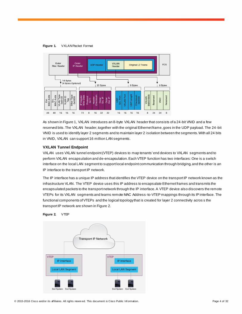
Figure 1. VXLAN Packet Format
As shown in Figure 1, VXLAN introduces an 8-byte VXLAN header that consists of a 24-bit VNID and a few
reserved bits. The VXLAN header, together with the original Ethernet frame, goes in the UDP payload. The 24 -bit
VNID is used to identify layer 2 segments and to maintain layer 2 isolation between the segments. With all 24 bits
in VNID, VXLAN can support 16 million LAN segments.
VXLAN Tunnel Endpoint
VXLAN uses VXLAN tunnel endpoint (VTEP) devices to map tenants' end devices to VXLAN segments and to
perform VXLAN encapsulation and de-encapsulation. Each VTEP function has two interfaces: One is a switch
interface on the local LAN segment to support local endpoint communication through bridging, and the other is an
IP interface to the transport IP network.
The IP interface has a unique IP address that identifies the VTEP device on the transport IP network known as the
infrastructure VLAN. The VTEP device uses this IP address to encapsulate Ethernet frames and transmits the
encapsulated packets to the transport network through the IP interface. A VTEP device also discovers the remote
VTEPs for its VXLAN segments and learns remote MAC Address -to-VTEP mappings through its IP interface. The
functional components of VTEPs and the logical topology that is created for layer 2 connectivity acros s the
transport IP network are shown in Figure 2.
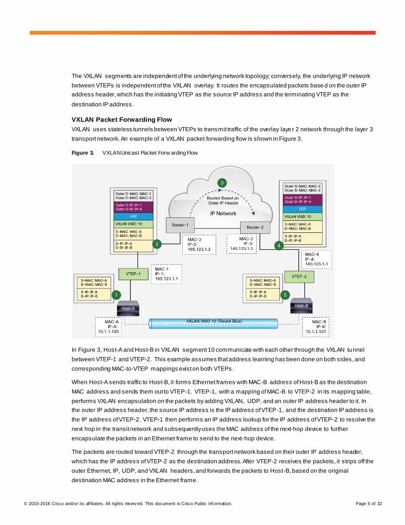
Figure 2. VTEP
© 2015-2016 Cisco and/or its affiliates. All rights reserv ed. This document is Cisco Public Inf ormation. Page 5 of 32
The VXLAN segments are independent of the underlying network topology; conversely, the underlying IP network
between VTEPs is independent of the VXLAN overlay. It routes the encapsulated packets base d on the outer IP
address header, which has the initiating VTEP as the source IP address and the terminating VTEP as the
destination IP address.
VXLAN Packet Forwarding Flow
VXLAN uses stateless tunnels between VTEPs to transmit traffic of the overlay layer 2 network through the layer 3
transport network. An example of a VXLAN packet forwarding flow is shown in Figure 3.
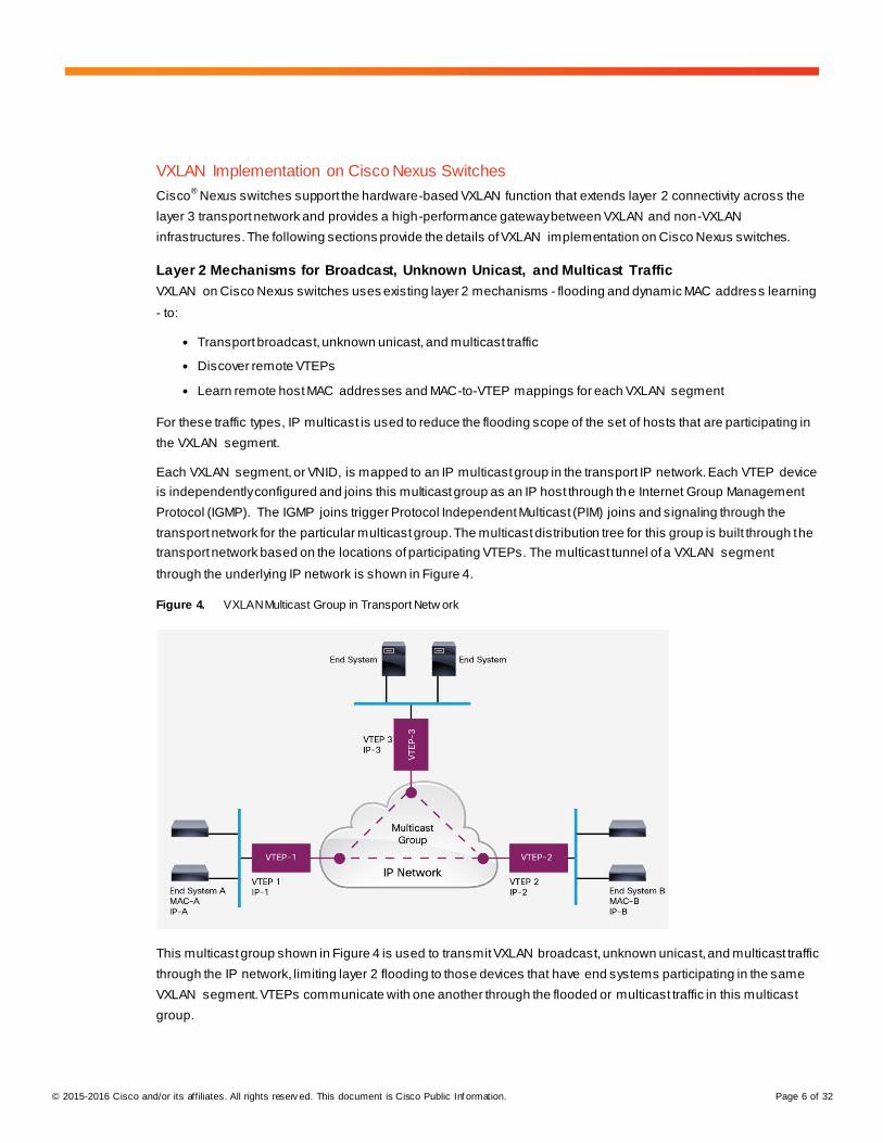
Figure 3. VXLAN Unicast Packet Forw arding Flow
In Figure 3, Host-A and Host-B in VXLAN segment 10 communicate with each other through the VXLAN tunnel
between VTEP-1 and VTEP-2. This example assumes that address learning has been done on both sides, and
corresponding MAC-to-VTEP mappings exist on both VTEPs.
When Host-A sends traffic to Host-B, it forms Ethernet frames with MAC-B address of Host-B as the destination
MAC address and sends them out to VTEP-1. VTEP-1, with a mapping of MAC-B to VTEP-2 in its mapping table,
performs VXLAN encapsulation on the packets by adding VXLAN, UDP, and an outer IP address header to it. In
the outer IP address header, the source IP address is the IP address of VTEP-1, and the destination IP address is
the IP address of VTEP-2. VTEP-1 then performs an IP address lookup for the IP address of VTEP-2 to resolve the
next hop in the transit network and subsequently uses the MAC address of the next-hop device to further
encapsulate the packets in an Ethernet frame to send to the next-hop device.
The packets are routed toward VTEP-2 through the transport network based on their outer IP address header,
which has the IP address of VTEP-2 as the destination address. After VTEP-2 receives the packets, it strips off the
outer Ethernet, IP, UDP, and VXLAN headers, and forwards the packets to Host-B, based on the original
destination MAC address in the Ethernet frame.
© 2015-2016 Cisco and/or its affiliates. All rights reserv ed. This document is Cisco Public Inf ormation. Page 6 of 32
VXLAN Implementation on Cisco Nexus Switches
Cisco® Nexus switches support the hardware-based VXLAN function that extends layer 2 connectivity across the
layer 3 transport network and provides a high-performance gateway between VXLAN and non-VXLAN
infrastructures. The following sections provide the details of VXLAN implementation on Cisco Nexus switches.
Layer 2 Mechanisms for Broadcast, Unknown Unicast, and Multicast Traffic
VXLAN on Cisco Nexus switches uses existing layer 2 mechanisms - flooding and dynamic MAC address learning
- to:
● Transport broadcast, unknown unicast, and multicast traffic
● Discover remote VTEPs
● Learn remote host MAC addresses and MAC-to-VTEP mappings for each VXLAN segment
For these traffic types, IP multicast is used to reduce the flooding scope of the set of hosts that are participating in
the VXLAN segment.
Each VXLAN segment, or VNID, is mapped to an IP multicast group in the transport IP network. Each VTEP device
is independently configured and joins this multicast group as an IP host through the Internet Group Management
Protocol (IGMP). The IGMP joins trigger Protocol Independent Multicast (PIM) joins and signaling through the
transport network for the particular multicast group. The multicast distribution tree for this group is built through the
transport network based on the locations of participating VTEPs. The multicast tunnel of a VXLAN segment
through the underlying IP network is shown in Figure 4.
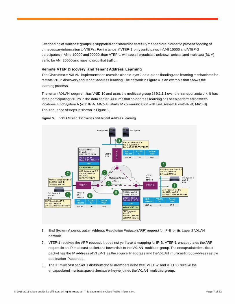
Figure 4. VXLAN Multicast Group in Transport Netw ork
This multicast group shown in Figure 4 is used to transmit VXLAN broadcast, unknown unicast, and multicast traffic
through the IP network, limiting layer 2 flooding to those devices that have end systems participating in the same
VXLAN segment. VTEPs communicate with one another through the flooded or multicast traffic in this multicast
group.
© 2015-2016 Cisco and/or its affiliates. All rights reserv ed. This document is Cisco Public Inf ormation. Page 7 of 32
Overloading of multicast groups is supported and should be carefully mapped out in order to prevent flooding of
unnecessary information to VTEPs. For instance, if VTEP-1 only participates in VNI 10000 and VTEP-2
participates in VNIs 10000 and 20000, than VTEP-1 will see all broadcast, unknown unicast and multicast (BUM)
traffic for VNI 20000 and have to drop that traffic.
Remote VTEP Discovery and Tenant Address Learning
The Cisco Nexus VXLAN implementation uses the classic layer 2 data-plane flooding and learning mechanisms for
remote VTEP discovery and tenant address learning. The network in Figure 4 is an example that shows the
learning process.
The tenant VXLAN segment has VNID 10 and uses the multicast group 239.1.1.1 over the transport network. It has
three participating VTEPs in the data center. Assume that no address learning has been performed between
locations. End System A (with IP-A, MAC-A) starts IP communication with End System B (with IP-B, MAC-B).
The sequence of steps is shown in Figure 5.
Figure 5. VXLAN Peer Discoveries and Tenant Address Learning
1. End System A sends out an Address Resolution Protocol (ARP) request for IP-B on its Layer 2 VXLAN
network.
2. VTEP-1 receives the ARP request. It does not yet have a mapping for IP-B. VTEP-1 encapsulates the ARP
request in an IP multicast packet and forwards it to the VXLAN multicast group. The encapsulated multicast
packet has the IP address of VTEP-1 as the source IP address and the VXLAN multicast group address as the
destination IP address.
3. The IP multicast packet is distributed to all members in the tree. VTEP-2 and VTEP-3 receive the
encapsulated multicast packet because they've joined the VXLAN multicast group.
© 2015-2016 Cisco and/or its affiliates. All rights reserv ed. This document is Cisco Public Inf ormation. Page 8 of 32
They de-encapsulate the packet and check its VNID in the VXLAN header. If it matches their configured
VXLAN segment VNID, they forward the ARP request to their local VXLAN network. They also learn the IP
address of VTEP-1 from the outer IP address header and inspect the packet to learn the MAC address of End
System A, placing this mapping in the local table.
4. End System B receives the ARP request forwarded by VTEP-2. It responds with its own MAC address
(MAC-B), and learns the IP-A-to-MAC-A mapping.
5. VTEP-2 receives the ARP reply of End System B that has MAC-A as the destination MAC address. It now
knows about MAC-A-to-IP-1 mapping. It can use the unicast tunnel to forward the ARP reply back to VTEP-1.
In the encapsulated unicast packet, the source IP address is IP-2 and the destination IP address is IP-1.
The ARP reply is encapsulated in the UDP payload.
6. VTEP-1 receives the encapsulated ARP reply from VTEP-2. It de-encapsulates and forwards the ARP reply to
End System A. It also learns the IP address of VTEP-2 from the outer IP address header and inspects the
original packet to learn MAC-B-to-IP-2 mapping.
7. Subsequent IP packets between End Systems A and B are unicast forwarded, based on the mapping
information on VTEP-1 and VTEP-2, using the VXLAN tunnel between them.
8. VTEP-1 can optionally perform proxy ARPs for subsequent ARP requests for IP-B to reduce the flooding over
the transport network.
VXLAN Hardware and Software Support
Cisco Nexus switches can support VXLAN as long as the right hardware, software, and licenses are used.
What is needed to support VXLAN on Cisco Nexus switches:
● Cisco Nexus 5600 Series Switches
◦ Software - Cisco NX-OS 7.1(0)N1(1) or later
◦ License - LAN Enterprise Services (Requires LAN Base)
Sample Underlay Configuration
The following sample underlay configuration is used as the base configuration on which we build the Layer 2 and
Layer 3 VXLAN Gateways on.
feature ospf
feature pim
ip pim rp-address 23.23.23.23 group-list 224.1.1.0/24 bidir RP is on another device in
the network
vlan 100
interface Ethernet1/48 South facing port to host
switchport mode trunk
interface Ethernet1/1 North facing port to IP Core
no switchport
mtu 9216
ip address 40.40.40.2/24
ip router ospf 1 area 0.0.0.0
© 2015-2016 Cisco and/or its affiliates. All rights reserv ed. This document is Cisco Public Inf ormation. Page 9 of 32
ip pim sparse-mode
router ospf 1
Configuring a Layer 2 VXLAN Gateway on a Cisco Nexus 5600
Complete these steps to configure VXLAN on the Cisco Nexus 5600:
1. Before configuring VXLAN-specific commands, the underlay must be configured. An example configuration is
included in the “Sample Underlay Configuration” Section.
2. Enable VXLAN features
feature nv overlay
feature vn-segment-vlan-based
3. Map VXLAN VNIs to VLANs
vlan 100
vn-segment 8500
4. Create a loopback to be used as the source for the VTEP
interface loopback1
ip address 10.3.3.3/32
ip router ospf 1 area 0.0.0.0
ip pim sparse-mode
5. Create the network virtualization endpoint (nve). This is your encapsulation and decapsulation point.
interface nve1
no shutdown
source-interface loopback1
member vni 8500 mcast-group 224.1.1.5
Configuring a Layer 3 VXLAN Gateway on a Cisco Nexus 5600
Complete these steps to configure VXLAN on the Cisco Nexus 5600:
1. Before configuring VXLAN-specific commands, the underlay must be configured. An example configuration is
included in the “Sample Underlay Configuration” Section.
2. Enable VXLAN features
feature nv overlay
feature vn-segment-vlan-based
feature interface-vlan
3. Map VXLAN VNIs to VLANs
vlan 100
vn-segment 8500
4. Create a loopback to be used as the source for the VTEP
interface loopback1
ip address 10.3.3.3/32
ip router ospf 1 area 0.0.0.0
ip pim sparse-mode
© 2015-2016 Cisco and/or its affiliates. All rights reserv ed. This document is Cisco Public Inf ormation. Page 10 of 32
5. Create the network virtualization endpoint (nve). This is your encapsulation and decapsulation point.
interface nve1
no shutdown
source-interface loopback1
member vni 8500 mcast-group 224.1.1.5
6. Create your Layer 3 SVI
interface Vlan100
no shutdown
ip address 100.1.100.1/24
ip router ospf 1 area 0.0.0.0
Cisco Nexus 5600 VXLAN Scale
For the 7.1(0)N1(1) release of NX-OS, the supported scale numbers are as follows:
Local VTEPs 1
VTEPs 1000
Host VTEPs 128
VNIs 650
DGroups 200
● Local VTEPs are the hardware based VTEPs on the Nexus 5600 Series Switches
● VTEPs refers to the number of remote VTEPs supported within the VXLAN Fabric
● Host VTEPs refers to the software based VTEPs on the hypervisor
● VNIs are the Segments in a VXLAN fabric
● DGroups (Destination Groups) are the multicast groups used for VXLAN traffic
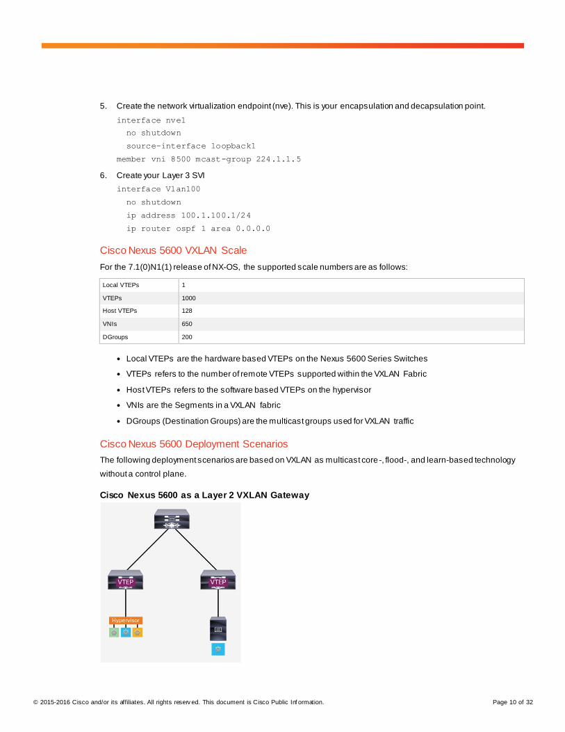
Cisco Nexus 5600 Deployment Scenarios
The following deployment scenarios are based on VXLAN as multicast core-, flood-, and learn-based technology
without a control plane.
Cisco Nexus 5600 as a Layer 2 VXLAN Gateway
© 2015-2016 Cisco and/or its affiliates. All rights reserv ed. This document is Cisco Public Inf ormation. Page 11 of 32
The Cisco Nexus 5600 can act as a VXLAN VTEP, providing both encapsulation and de -capsulation of classical
Ethernet and VXLAN packets. In this scenario a trunk port is connected from a virtualized host through a virtual
switch and adds dot1q tags to the classical Ethernet frames. The Cisco Nexus 5600 then takes the tagged frames
and if the dot1q tag matches a configured VLAN to VNI mapping, encapsulates it with a VXLAN header.
Since a physical switch is being used for VXLAN encapsulation, traffic between virtual and physical hosts is now
supported, something not possible on a virtual switch.
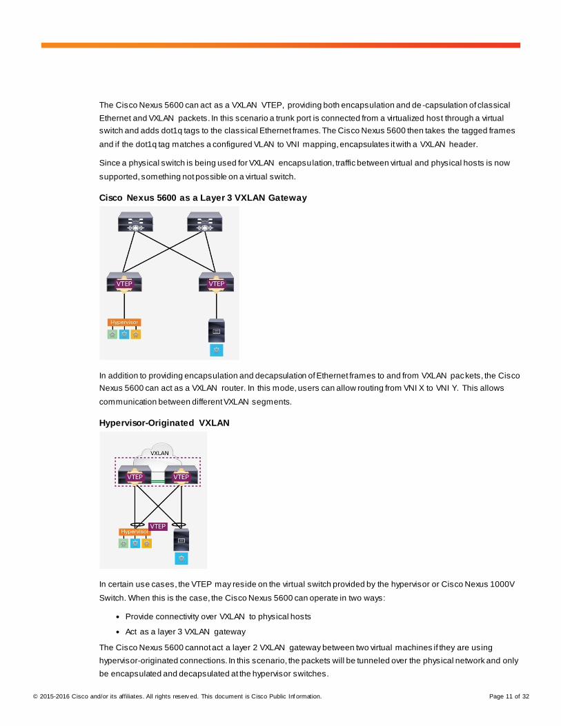
Cisco Nexus 5600 as a Layer 3 VXLAN Gateway
In addition to providing encapsulation and decapsulation of Ethernet frames to and from VXLAN packets, the Cisco
Nexus 5600 can act as a VXLAN router. In this mode, users can allow routing from VNI X to VNI Y. This allows
communication between different VXLAN segments.
Hypervisor-Originated VXLAN
In certain use cases, the VTEP may reside on the virtual switch provided by the hypervisor or Cisco Nexus 1000V
Switch. When this is the case, the Cisco Nexus 5600 can operate in two ways:
● Provide connectivity over VXLAN to physical hosts
● Act as a layer 3 VXLAN gateway
The Cisco Nexus 5600 cannot act a layer 2 VXLAN gateway between two virtual machines if they are using
hypervisor-originated connections. In this scenario, the packets will be tunneled over the physical network and only
be encapsulated and decapsulated at the hypervisor switches.
© 2015-2016 Cisco and/or its affiliates. All rights reserv ed. This document is Cisco Public Inf ormation. Page 12 of 32
Underlay Requirements for VXLAN
The Cisco Nexus 5600 and any other switches participating in the VXLAN fabric with a 5600 switch have to meet
the following requirements in the underlay for the overlay to function properly:
● Layer 3 routing must be configured (Open Shortest Path First [OSPF], Enhanced Interior Gateway Routing
Protocol [EIGRP], Static Routing, etc.)
● PIM-BiDir Multicast (PIM-ASM is not supported for VXLAN)
● Encapsulation and decapsulation points must be layer 3-routed ports
● Layer 3-facing ports need to add at least 50 bytes to the MTU or servers MTU reduced by 50 bytes
VXLAN Designs
Following are some recommended design examples that illustrate how to deploy a VXLAN fabric with Cisco Nexus
switches.
Centralized Gateway with Inter-VXLAN Routing in the Core/Aggregation
In this topology the leaf switches provide only layer 2 gateway VXLAN functionality and allow the spine/aggregation
layer to provide the VXLAN routing capability. There are no VTEPs configured on the hypervisor -based switches. It
is important to note that all default gateways reside on the core/aggregation switches, as distribution of gateways at
the leaf layer cannot work without a control plane protocol.
Additionally, it is important to note that any traffic with the appropriate 802.1q tag into the leaf layer will be VXLAN-
encapsulated. Cisco NX-OS Software also provides the MAC address of the host in both the leaf and
core/aggregation layer in this topology, and will show the MAC as learned over the network virtualization endpoint
(NVE) interface in the core/aggregation layer.
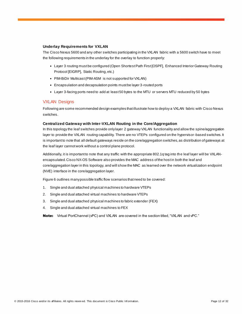
Figure 6 outlines many possible traffic flow scenarios that need to be covered:
1. Single and dual attached physical machines to hardware VTEPs
2. Single and dual attached virtual machines to hardware VTEPs
3. Single and dual attached physical machines to fabric extender (FEX)
4. Single and dual attached virtual machines to FEX
Note: Virtual PortChannel (vPC) and VXLAN are covered in the section titled, “VXLAN and vPC.”
© 2015-2016 Cisco and/or its affiliates. All rights reserv ed. This document is Cisco Public Inf ormation. Page 13 of 32
Figure 6. Traff ic Flow Scenarios
Single and Dual Attached Physical Machines to Hardware VTEPs
This is one of the most straightforward topologies that can be utilized in a VXLAN fabric. In this scenario, the
physical machines are directly connected to a single or pair of Cisco Nexus 5600 switches performing VXLAN layer
2 encapsulation and decapsulation. When dual connecting, a traditional vPC is configured on the Cisco Nexus
5600 with the peer-link between the two physical switches.
● A classical Ethernet frame is forwarded from the physical machine to the Cisco Nexus 5600 Switch
● The frame is then encapsulated based on the VLAN-to-VNI mapping configured
Single and Dual Attached Virtual Machines to Hardware VTEPs
Connecting virtual machines into a VXLAN fabric is very common as it helps put any segment anywhere in the
network, instead of limiting it based on physical pods. This scenario works exactly like the previous one except that
a virtual switch will be instead connecting to the Cisco Nexus 5600. In this scenario, the following packet flow
occurs:
● A classic Ethernet frame is forwarded from the virtual machine through the hypervisor switch
● The frame reaches the Cisco Nexus 5600 and is encapsulated based on the VLAN-to-VNI mapping
configured
When using in a virtual environment, it is necessary that the hypervisor switch adds the 802.1q tag to the traffic
before forwarding out of the physical ports. In this scenario, VXLAN is not running on the hypervisor switch.
Single and Dual Attached Physical Machines to FEX
To help manage the networking aspect of many machines in only a few central areas ( the parent switches) a FEX
can be utilized when there is a VXLAN Fabric. The FEX devices do not perform any VXLAN functionality and
cannot read any VXLAN encapsulated traffic. Instead the FEX transmits only classical Ethernet frames to the
parent switch where any VTEP discovery, MAC learning, encapsulation or decapsulation are to occur.
© 2015-2016 Cisco and/or its affiliates. All rights reserv ed. This document is Cisco Public Inf ormation. Page 14 of 32
It is important to remember that there is no connection between two FEX switches when vPC is being utilized, but
any peer-links are on the parent switches.
Single and Dual Attached Virtual Machines to FEX
As long as the hypervisor is still utilizing classical Ethernet you can single attach or dual attach FEX switches to
help aggregate the traffic into the hardware VTEP. When using a FEX, only classical Ethernet frames are
transmitted to and from the FEX. We still rely on the Cisco Nexus 5600 to do any VXLAN encapsulation and
decapsulation. The traffic flow will be the same as the previous scenario, but will have to flow through the virtual
switch hosted by the hypervisor to reach the FEX. Single and Dual Attached (Distributed Gateway) Hypervisor-
Originated VXLAN to the Top of Rack (ToR)
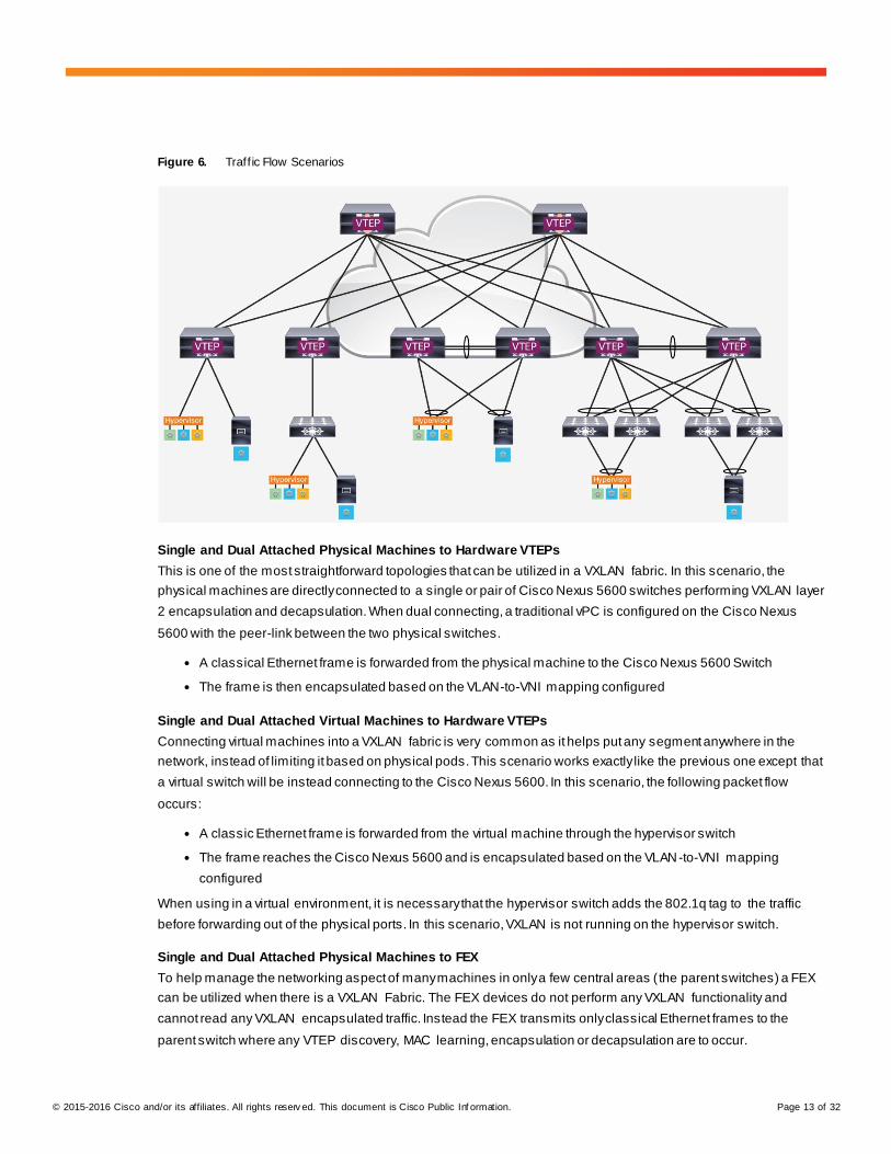
In some existing VXLAN deployments, the hypervisor switch may be performing VXLAN functions (Figure 7). In
those scenarios it is important to follow best practices. Two verified topologies that can be utilized include:
● Single attached hypervisor-originated VXLAN with layer 3 VXLAN routing at the ToR
● Distributed Gateway (dual attached) hypervisor-originated VXLAN with layer 3 VXLAN routing at the ToR
Figure 7. Topologies
In these two topologies, the hypervisor switch will do layer 2 VXLAN bridging of the frames coming to and from the
virtual machines. After that, one of two scenarios can occur:
● If the destination is a physical device, the Cisco Nexus 5600 will decapsulate the traffic if in the same
segment or it will route and then decapsulate if in a different segment.
● If the destination is another virtual machine in a separate segment, the Cisco Nexus 5600 will VXLAN -route
that traffic.
Additionally, if the destination is another virtual machine in the same segment, the traffic will simply be forwarded
over the Cisco Nexus 5600 to the destination hypervisor as if it were any other IP-based traffic.
© 2015-2016 Cisco and/or its affiliates. All rights reserv ed. This document is Cisco Public Inf ormation. Page 15 of 32
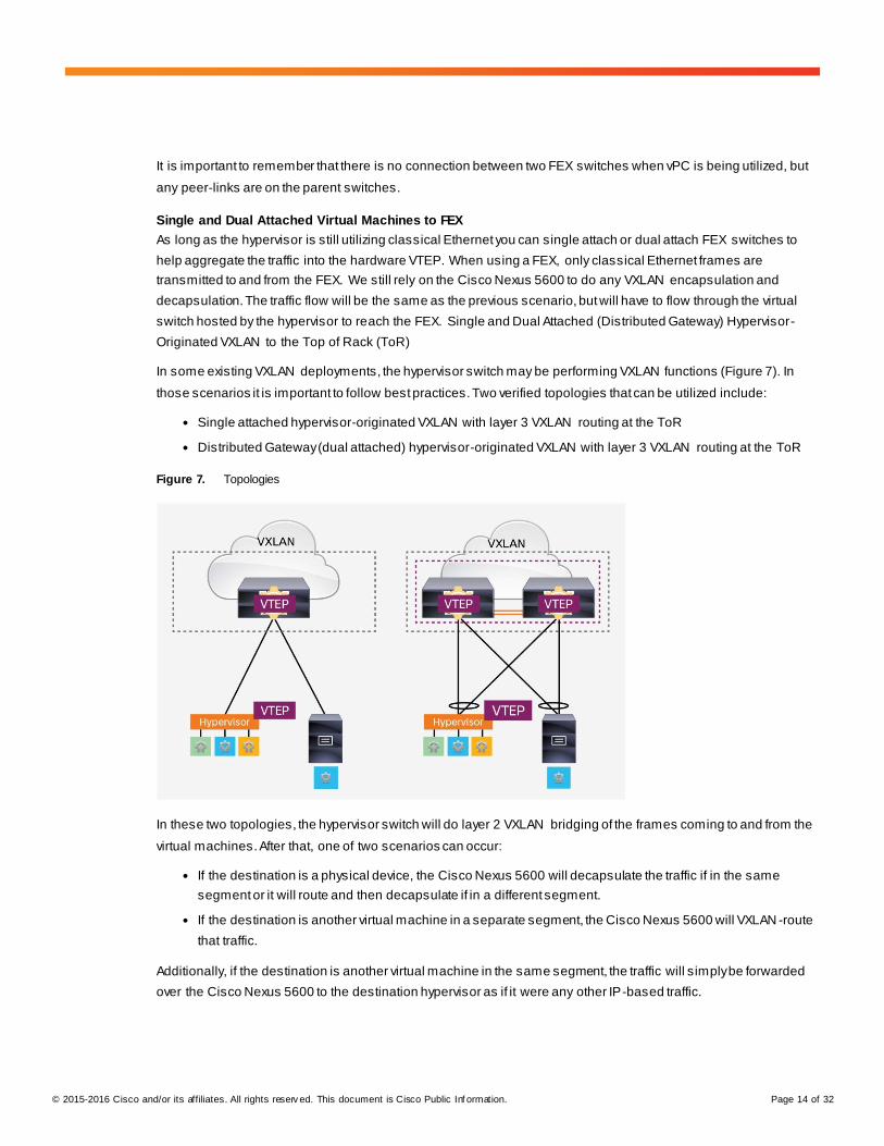
Single Attached Hypervisor-Originated VXLAN to FEX
When utilizing a hypervisor-originated VXLAN packet with a FEX, it is important that both the hypervisor switch and
FEX are only single attached (Figure 8). Dual attaching the FEX and the Cisco Nexus 5600 in this scenario is not
supported.
Figure 8. Single Attached Hypervisor Switch and FEX
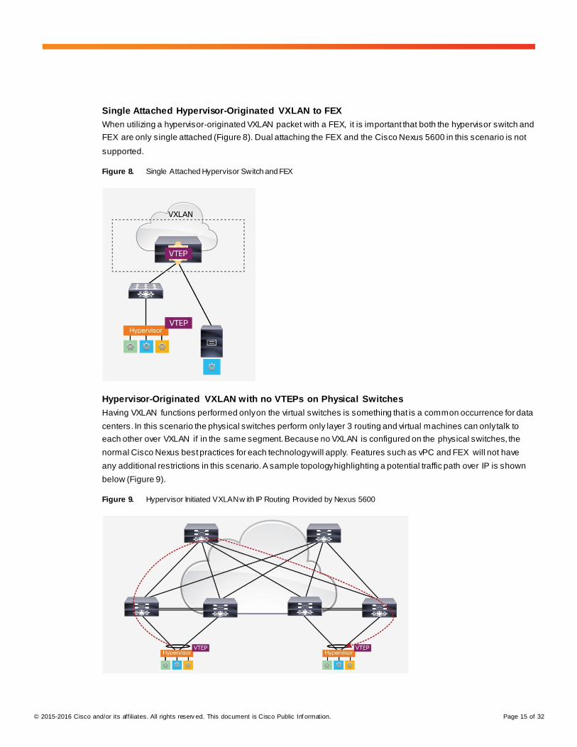
Hypervisor-Originated VXLAN with no VTEPs on Physical Switches
Having VXLAN functions performed only on the virtual switches is something that is a common occurrence for data
centers. In this scenario the physical switches perform only layer 3 routing and virtual machines can only talk to
each other over VXLAN if in the same segment. Because no VXLAN is configured on the physical switches, the
normal Cisco Nexus best practices for each technology will apply. Features such as vPC and FEX will not have
any additional restrictions in this scenario. A sample topology highlighting a potential traffic path over IP is shown
below (Figure 9).
Figure 9. Hypervisor Initiated VXLAN w ith IP Routing Provided by Nexus 5600
© 2015-2016 Cisco and/or its affiliates. All rights reserv ed. This document is Cisco Public Inf ormation. Page 16 of 32
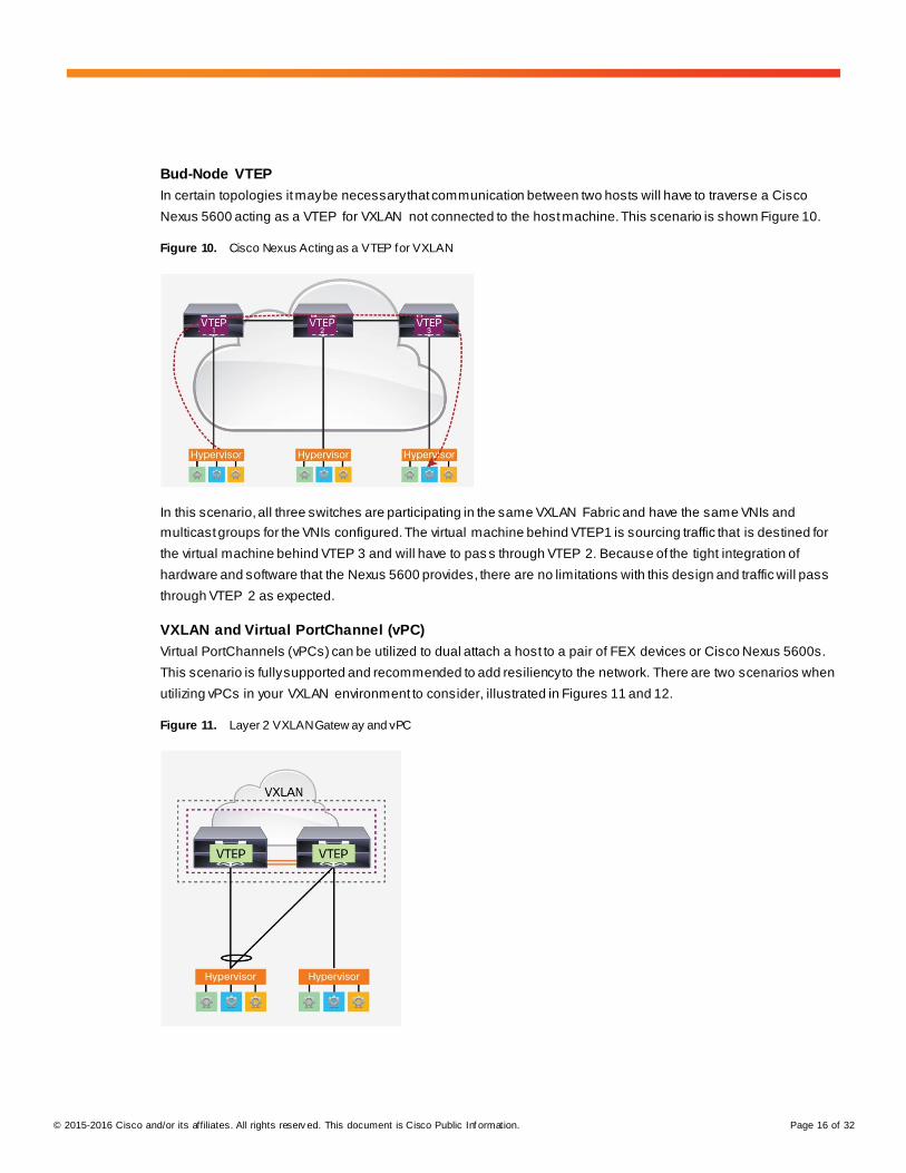
Bud-Node VTEP
In certain topologies it may be necessary that communication between two hosts will have to traverse a Cisco
Nexus 5600 acting as a VTEP for VXLAN not connected to the host machine. This scenario is shown Figure 10.
Figure 10. Cisco Nexus Acting as a VTEP for VXLAN
In this scenario, all three switches are participating in the same VXLAN Fabric and have the same VNIs and
multicast groups for the VNIs configured. The virtual machine behind VTEP1 is sourcing traffic that is destined for
the virtual machine behind VTEP 3 and will have to pas s through VTEP 2. Because of the tight integration of
hardware and software that the Nexus 5600 provides, there are no limitations with this design and traffic will pass
through VTEP 2 as expected.
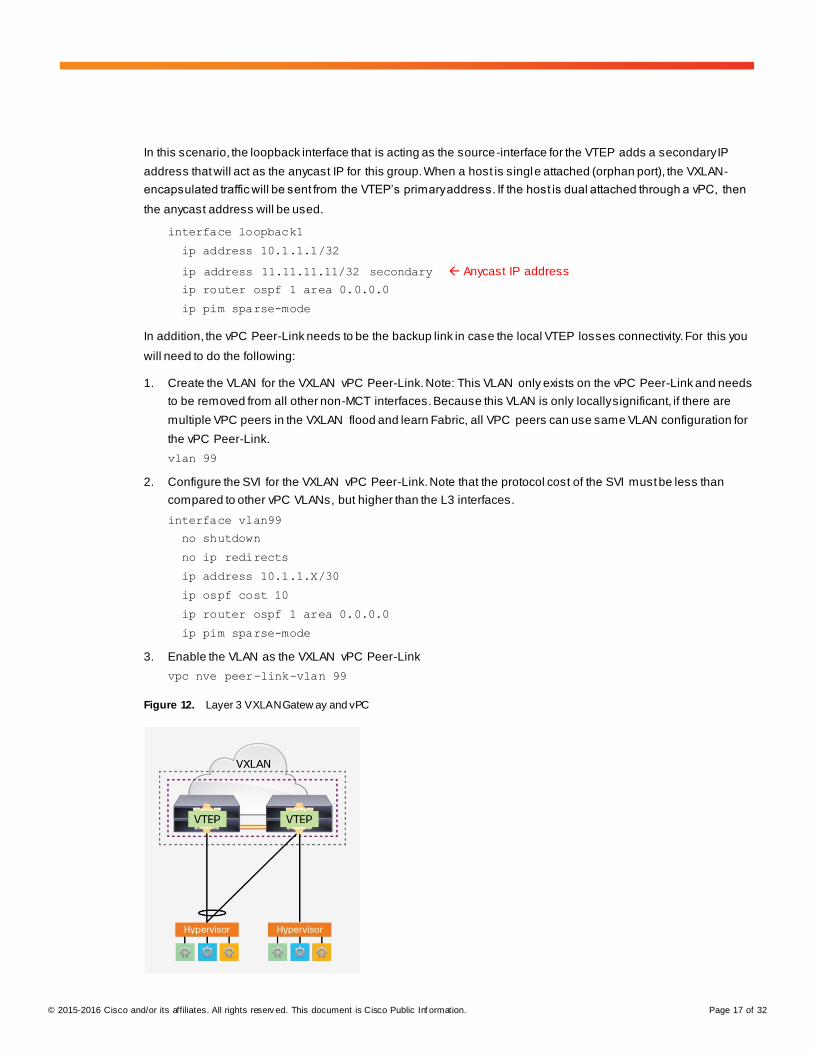
VXLAN and Virtual PortChannel (vPC)
Virtual PortChannels (vPCs) can be utilized to dual attach a host to a pair of FEX devices or Cisco Nexus 5600s.
This scenario is fully supported and recommended to add resiliency to the network. There are two scenarios when
utilizing vPCs in your VXLAN environment to consider, illustrated in Figures 11 and 12.
Figure 11. Layer 2 VXLAN Gatew ay and vPC
© 2015-2016 Cisco and/or its affiliates. All rights reserv ed. This document is Cisco Public Inf ormation. Page 17 of 32
In this scenario, the loopback interface that is acting as the source-interface for the VTEP adds a secondary IP
address that will act as the anycast IP for this group. When a host is single attached (orphan port), the VXLAN-
encapsulated traffic will be sent from the VTEP’s primary address. If the host is dual attached through a vPC, then
the anycast address will be used.
interface loopback1
ip address 10.1.1.1/32
ip address 11.11.11.11/32 secondary Anycast IP address
ip router ospf 1 area 0.0.0.0
ip pim sparse-mode
In addition, the vPC Peer-Link needs to be the backup link in case the local VTEP losses connectivity. For this you
will need to do the following:
1. Create the VLAN for the VXLAN vPC Peer-Link. Note: This VLAN only exists on the vPC Peer-Link and needs
to be removed from all other non-MCT interfaces. Because this VLAN is only locally significant, if there are
multiple VPC peers in the VXLAN flood and learn Fabric, all VPC peers can use same VLAN configuration for
the vPC Peer-Link.
vlan 99
2. Configure the SVI for the VXLAN vPC Peer-Link. Note that the protocol cost of the SVI must be less than
compared to other vPC VLANs, but higher than the L3 interfaces.
interface vlan99
no shutdown
no ip redirects
ip address 10.1.1.X/30
ip ospf cost 10
ip router ospf 1 area 0.0.0.0
ip pim sparse-mode
3. Enable the VLAN as the VXLAN vPC Peer-Link
vpc nve peer-link-vlan 99
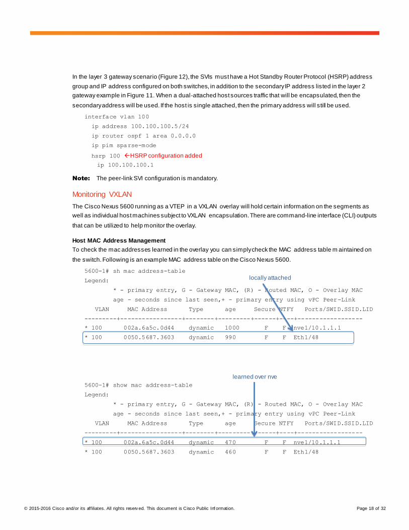
Figure 12. Layer 3 VXLAN Gatew ay and vPC
© 2015-2016 Cisco and/or its affiliates. All rights reserv ed. This document is Cisco Public Inf ormation. Page 18 of 32
In the layer 3 gateway scenario (Figure 12), the SVIs must have a Hot Standby Router Protocol (HSRP) address
group and IP address configured on both switches, in addition to the secondary IP address listed in the layer 2
gateway example in Figure 11. When a dual-attached host sources traffic that will be encapsulated, then the
secondary address will be used. If the host is single attached, then the primary address will still be used.
interface vlan 100
ip address 100.100.100.5/24
ip router ospf 1 area 0.0.0.0
ip pim sparse-mode
hsrp 100 HSRP configuration added
ip 100.100.100.1
Note: The peer-link SVI configuration is mandatory.
Monitoring VXLAN
The Cisco Nexus 5600 running as a VTEP in a VXLAN overlay will hold certain information on the segments as
well as individual host machines subject to VXLAN encapsulation. There are command-line interface (CLI) outputs
that can be utilized to help monitor the overlay.
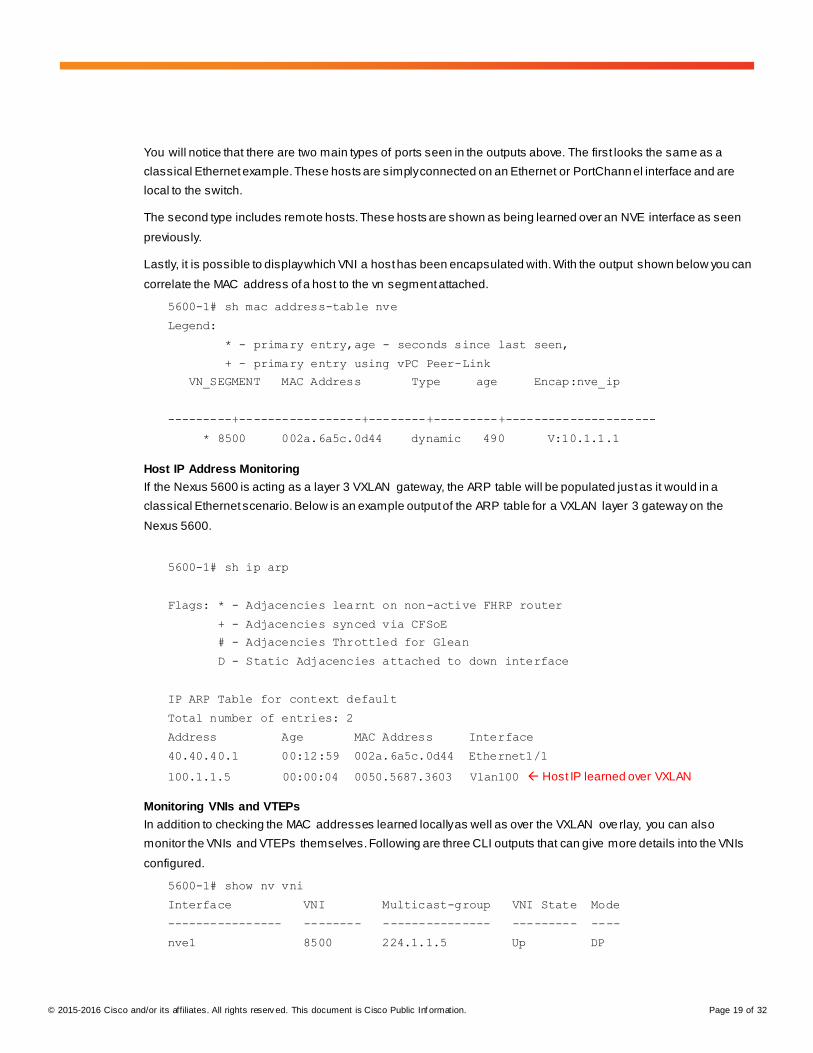
Host MAC Address Management
To check the mac addresses learned in the overlay you can simply check the MAC address table m aintained on
the switch. Following is an example MAC address table on the Cisco Nexus 5600.
5600-1# sh mac address-table
Legend:
* - primary entry, G - Gateway MAC, (R) - Routed MAC, O - Overlay MAC
age - seconds since last seen,+ - primary entry using vPC Peer-Link
VLAN MAC Address Type age Secure NTFY Ports/SWID.SSID.LID
---------+-----------------+--------+---------+------+----+------------------
* 100 002a.6a5c.0d44 dynamic 1000 F F nve1/10.1.1.1
* 100 0050.5687.3603 dynamic 990 F F Eth1/48
5600-1# show mac address-table
Legend:
* - primary entry, G - Gateway MAC, (R) - Routed MAC, O - Overlay MAC
age - seconds since last seen,+ - primary entry using vPC Peer-Link
VLAN MAC Address Type age Secure NTFY Ports/SWID.SSID.LID
---------+-----------------+--------+---------+------+----+------------------
* 100 002a.6a5c.0d44 dynamic 470 F F nve1/10.1.1.1
* 100 0050.5687.3603 dynamic 460 F F Eth1/48
locally attached
learned over nve
© 2015-2016 Cisco and/or its affiliates. All rights reserv ed. This document is Cisco Public Inf ormation. Page 19 of 32
You will notice that there are two main types of ports seen in the outputs above. The first looks the same as a
classical Ethernet example. These hosts are simply connected on an Ethernet or PortChannel interface and are
local to the switch.
The second type includes remote hosts. These hosts are shown as being learned over an NVE interface as seen
previously.
Lastly, it is possible to display which VNI a host has been encapsulated with. With the output shown below you can
correlate the MAC address of a host to the vn segment attached.
5600-1# sh mac address-table nve
Legend:
* - primary entry,age - seconds since last seen,
+ - primary entry using vPC Peer-Link
VN_SEGMENT MAC Address Type age Encap:nve_ip
---------+-----------------+--------+---------+---------------------
* 8500 002a.6a5c.0d44 dynamic 490 V:10.1.1.1
Host IP Address Monitoring
If the Nexus 5600 is acting as a layer 3 VXLAN gateway, the ARP table will be populated just as it would in a
classical Ethernet scenario. Below is an example output of the ARP table for a VXLAN layer 3 gateway on the
Nexus 5600.
5600-1# sh ip arp
Flags: * - Adjacencies learnt on non-active FHRP router
+ - Adjacencies synced via CFSoE
# - Adjacencies Throttled for Glean
D - Static Adjacencies attached to down interface
IP ARP Table for context default
Total number of entries: 2
Address Age MAC Address Interface
40.40.40.1 00:12:59 002a.6a5c.0d44 Ethernet1/1
100.1.1.5 00:00:04 0050.5687.3603 Vlan100 Host IP learned over VXLAN
Monitoring VNIs and VTEPs
In addition to checking the MAC addresses learned locally as well as over the VXLAN ove rlay, you can also
monitor the VNIs and VTEPs themselves. Following are three CLI outputs that can give more details into the VNIs
configured.
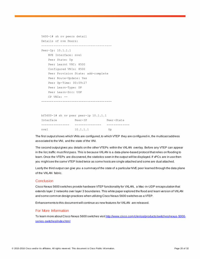
5600-1# show nv vni
Interface VNI Multicast-group VNI State Mode
---------------- -------- --------------- --------- ----
nve1 8500 224.1.1.5 Up DP
© 2015-2016 Cisco and/or its affiliates. All rights reserv ed. This document is Cisco Public Inf ormation. Page 20 of 32
5600-1# sh nv peers detail
Details of nve Peers:
----------------------------------------
Peer-Ip: 10.1.1.1
NVE Interface: nve1
Peer State: Up
Peer Learnt VNI: 8500
Configured VNIs: 8500
Peer Provision State: add-complete
Peer Route-Update: Yes
Peer Up-Time: 00:09:27
Peer Learn-Type: DP
Peer Learn-Src: UDP
CP VNIs: --
----------------------------------------
bf5600-1# sh nv peer peer-ip 10.1.1.1
Interface Peer-IP Peer-State
---------------- --------------- -------------
nve1 10.1.1.1 Up
The first output shows which VNIs are configured, to which VTEP they are configured in, the multicast address
associated to the VNI, and the state of the VNI.
The second output gives you details on the other VTEPs within the VXLAN overlay. Before any VTEP can appear
in the list, traffic must first pass. This is because VXLAN is a data-plane-based protocol that relies on flooding to
learn. Once the VTEPs are discovered, the statistics seen in the output will be displayed. If vPCs are in use then
you might see the same VTEP listed twice as some hosts are single attached and some are dual attached.
Lastly the third output can give you a summary of the state of a particular NVE peer learned through the data plane
of the VXLAN fabric.
Conclusion
Cisco Nexus 5600 switches provide hardware VTEP functionality for VXLAN, a Mac-in-UDP encapsulation that
extends layer 2 networks over layer 3 boundaries. This white paper explored the flood and learn version of VXLAN
and some common design practices when utilizing Cisco Nexus 5600 switches as a VTEP.
Enhancements to this document will continue as new features for VXLAN are released.
For More Information
To learn more about Cisco Nexus 5600 switches visit http://www.cisco.com/c/en/us/products/switches/nexus-5000-
series-switches/index.html
© 2015-2016 Cisco and/or its affiliates. All rights reserv ed. This document is Cisco Public Inf ormation. Page 21 of 32
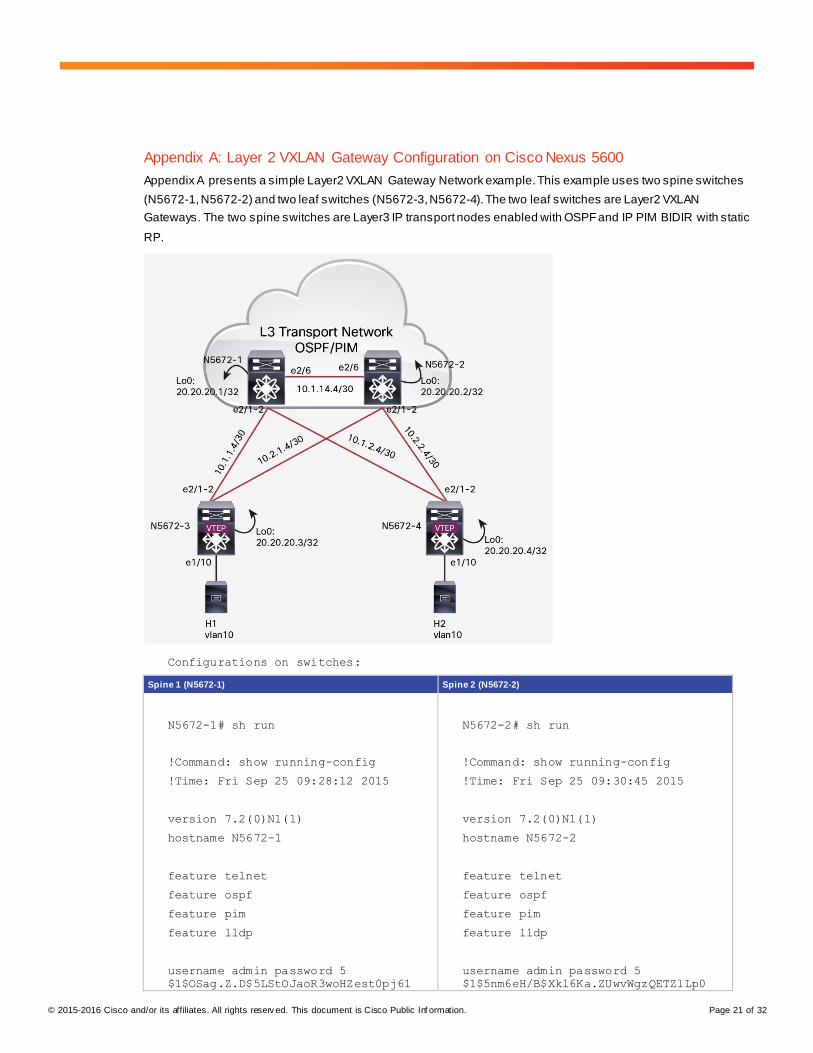
Appendix A: Layer 2 VXLAN Gateway Configuration on Cisco Nexus 5600
Appendix A presents a simple Layer2 VXLAN Gateway Network example. This example uses two spine switches
(N5672-1, N5672-2) and two leaf switches (N5672-3, N5672-4). The two leaf switches are Layer2 VXLAN
Gateways. The two spine switches are Layer3 IP transport nodes enabled with OSPF and IP PIM BIDIR with static
RP.
Configurations on switches:
Spine 1 (N5672-1) Spine 2 (N5672-2)
N5672-1# sh run
!Command: show running-config
!Time: Fri Sep 25 09:28:12 2015
version 7.2(0)N1(1)
hostname N5672-1
feature telnet
feature ospf
feature pim
feature lldp
username admin password 5
$1$OSag.Z.D$5LStOJaoR3woHZest0pj61
N5672-2# sh run
!Command: show running-config
!Time: Fri Sep 25 09:30:45 2015
version 7.2(0)N1(1)
hostname N5672-2
feature telnet
feature ospf
feature pim
feature lldp
username admin password 5
$1$5nm6eH/B$Xkl6Ka.ZUwvWgzQETZlLp0
© 2015-2016 Cisco and/or its affiliates. All rights reserv ed. This document is Cisco Public Inf ormation. Page 22 of 32
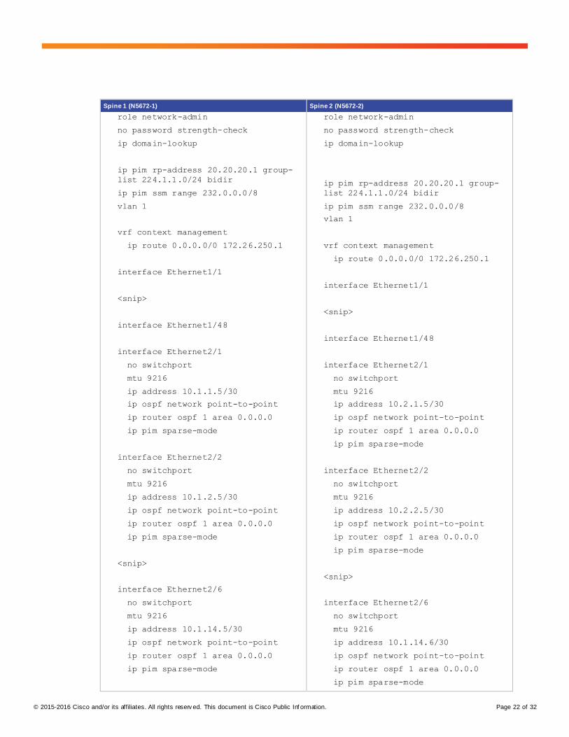
Spine 1 (N5672-1) Spine 2 (N5672-2)
role network-admin
no password strength-check
ip domain-lookup
ip pim rp-address 20.20.20.1 group-
list 224.1.1.0/24 bidir
ip pim ssm range 232.0.0.0/8
vlan 1
vrf context management
ip route 0.0.0.0/0 172.26.250.1
interface Ethernet1/1
<snip>
interface Ethernet1/48
interface Ethernet2/1
no switchport
mtu 9216
ip address 10.1.1.5/30
ip ospf network point-to-point
ip router ospf 1 area 0.0.0.0
ip pim sparse-mode
interface Ethernet2/2
no switchport
mtu 9216
ip address 10.1.2.5/30
ip ospf network point-to-point
ip router ospf 1 area 0.0.0.0
ip pim sparse-mode
<snip>
interface Ethernet2/6
no switchport
mtu 9216
ip address 10.1.14.5/30
ip ospf network point-to-point
ip router ospf 1 area 0.0.0.0
ip pim sparse-mode
role network-admin
no password strength-check
ip domain-lookup
ip pim rp-address 20.20.20.1 group-
list 224.1.1.0/24 bidir
ip pim ssm range 232.0.0.0/8
vlan 1
vrf context management
ip route 0.0.0.0/0 172.26.250.1
interface Ethernet1/1
<snip>
interface Ethernet1/48
interface Ethernet2/1
no switchport
mtu 9216
ip address 10.2.1.5/30
ip ospf network point-to-point
ip router ospf 1 area 0.0.0.0
ip pim sparse-mode
interface Ethernet2/2
no switchport
mtu 9216
ip address 10.2.2.5/30
ip ospf network point-to-point
ip router ospf 1 area 0.0.0.0
ip pim sparse-mode
<snip>
interface Ethernet2/6
no switchport
mtu 9216
ip address 10.1.14.6/30
ip ospf network point-to-point
ip router ospf 1 area 0.0.0.0
ip pim sparse-mode
© 2015-2016 Cisco and/or its affiliates. All rights reserv ed. This document is Cisco Public Inf ormation. Page 23 of 32
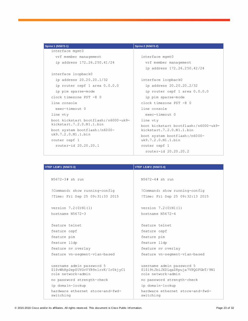
Spine 1 (N5672-1) Spine 2 (N5672-2)
interface mgmt0
vrf member management
ip address 172.26.250.41/24
interface loopback0
ip address 20.20.20.1/32
ip router ospf 1 area 0.0.0.0
ip pim sparse-mode
clock timezone PST -8 0
line console
exec-timeout 0
line vty
boot kickstart bootflash:/n6000-uk9-
kickstart.7.2.0.N1.1.bin
boot system bootflash:/n6000-
uk9.7.2.0.N1.1.bin
router ospf 1
router-id 20.20.20.1
interface mgmt0
vrf member management
ip address 172.26.250.42/24
interface loopback0
ip address 20.20.20.2/32
ip router ospf 1 area 0.0.0.0
ip pim sparse-mode
clock timezone PST -8 0
line console
exec-timeout 0
line vty
boot kickstart bootflash:/n6000-uk9-
kickstart.7.2.0.N1.1.bin
boot system bootflash:/n6000-
uk9.7.2.0.N1.1.bin
router ospf 1
router-id 20.20.20.2
VTEP LEAF1 (N5672-3) VTEP LEAF2 (N5672-4)
N5672-3# sh run
!Command: show running-config
!Time: Fri Sep 25 09:31:33 2015
version 7.2(0)N1(1)
hostname N5672-3
feature telnet
feature ospf
feature pim
feature lldp
feature nv overlay
feature vn-segment-vlan-based
username admin password 5
$1$vWhHp2ep$UYGvVYR9nlrrK/Ir0kjyC1
role network-admin
no password strength-check
ip domain-lookup
hardware ethernet store-and-fwd-
switching
N5672-4# sh run
!Command: show running-config
!Time: Fri Sep 25 09:32:13 2015
version 7.2(0)N1(1)
hostname N5672-4
feature telnet
feature ospf
feature pim
feature lldp
feature nv overlay
feature vn-segment-vlan-based
username admin password 5
$1$l9tJbiJX$LqaZ8puja7VPQGFGbT/9N1
role network-admin
no password strength-check
ip domain-lookup
hardware ethernet store-and-fwd-
switching
© 2015-2016 Cisco and/or its affiliates. All rights reserv ed. This document is Cisco Public Inf ormation. Page 24 of 32
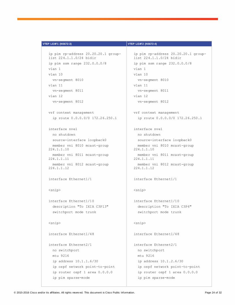
VTEP LEAF1 (N5672-3) VTEP LEAF2 (N5672-4)
ip pim rp-address 20.20.20.1 group-
list 224.1.1.0/24 bidir
ip pim ssm range 232.0.0.0/8
vlan 1
vlan 10
vn-segment 8010
vlan 11
vn-segment 8011
vlan 12
vn-segment 8012
vrf context management
ip route 0.0.0.0/0 172.26.250.1
interface nve1
no shutdown
source-interface loopback0
member vni 8010 mcast-group
224.1.1.10
member vni 8011 mcast-group
224.1.1.11
member vni 8012 mcast-group
224.1.1.12
interface Ethernet1/1
<snip>
interface Ethernet1/10
description "To IXIA C3P13"
switchport mode trunk
<snip>
interface Ethernet1/48
interface Ethernet2/1
no switchport
mtu 9216
ip address 10.1.1.6/30
ip ospf network point-to-point
ip router ospf 1 area 0.0.0.0
ip pim sparse-mode
ip pim rp-address 20.20.20.1 group-
list 224.1.1.0/24 bidir
ip pim ssm range 232.0.0.0/8
vlan 1
vlan 10
vn-segment 8010
vlan 11
vn-segment 8011
vlan 12
vn-segment 8012
vrf context management
ip route 0.0.0.0/0 172.26.250.1
interface nve1
no shutdown
source-interface loopback0
member vni 8010 mcast-group
224.1.1.10
member vni 8011 mcast-group
224.1.1.11
member vni 8012 mcast-group
224.1.1.12
interface Ethernet1/1
<snip>
interface Ethernet1/10
description "To IXIA C3P6"
switchport mode trunk
<snip>
interface Ethernet1/48
interface Ethernet2/1
no switchport
mtu 9216
ip address 10.1.2.6/30
ip ospf network point-to-point
ip router ospf 1 area 0.0.0.0
ip pim sparse-mode
© 2015-2016 Cisco and/or its affiliates. All rights reserv ed. This document is Cisco Public Inf ormation. Page 25 of 32
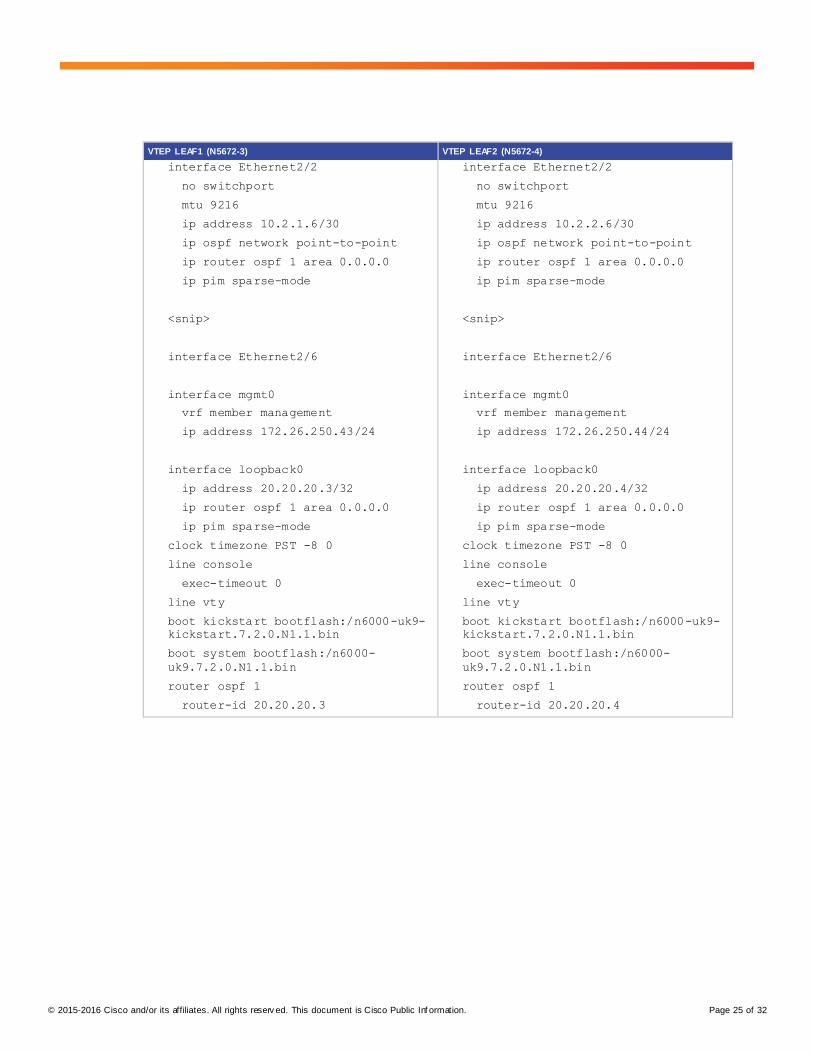
VTEP LEAF1 (N5672-3) VTEP LEAF2 (N5672-4)
interface Ethernet2/2
no switchport
mtu 9216
ip address 10.2.1.6/30
ip ospf network point-to-point
ip router ospf 1 area 0.0.0.0
ip pim sparse-mode
<snip>
interface Ethernet2/6
interface mgmt0
vrf member management
ip address 172.26.250.43/24
interface loopback0
ip address 20.20.20.3/32
ip router ospf 1 area 0.0.0.0
ip pim sparse-mode
clock timezone PST -8 0
line console
exec-timeout 0
line vty
boot kickstart bootflash:/n6000-uk9-
kickstart.7.2.0.N1.1.bin
boot system bootflash:/n6000-
uk9.7.2.0.N1.1.bin
router ospf 1
router-id 20.20.20.3
interface Ethernet2/2
no switchport
mtu 9216
ip address 10.2.2.6/30
ip ospf network point-to-point
ip router ospf 1 area 0.0.0.0
ip pim sparse-mode
<snip>
interface Ethernet2/6
interface mgmt0
vrf member management
ip address 172.26.250.44/24
interface loopback0
ip address 20.20.20.4/32
ip router ospf 1 area 0.0.0.0
ip pim sparse-mode
clock timezone PST -8 0
line console
exec-timeout 0
line vty
boot kickstart bootflash:/n6000-uk9-
kickstart.7.2.0.N1.1.bin
boot system bootflash:/n6000-
uk9.7.2.0.N1.1.bin
router ospf 1
router-id 20.20.20.4
© 2015-2016 Cisco and/or its affiliates. All rights reserv ed. This document is Cisco Public Inf ormation. Page 26 of 32
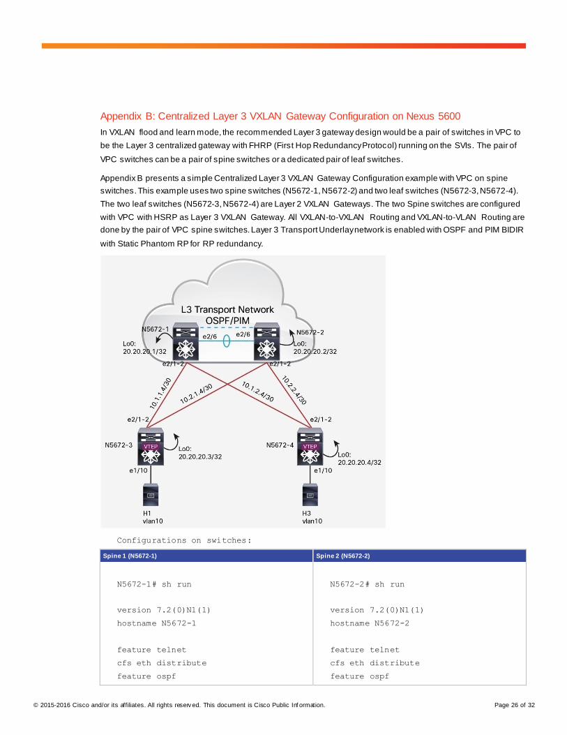
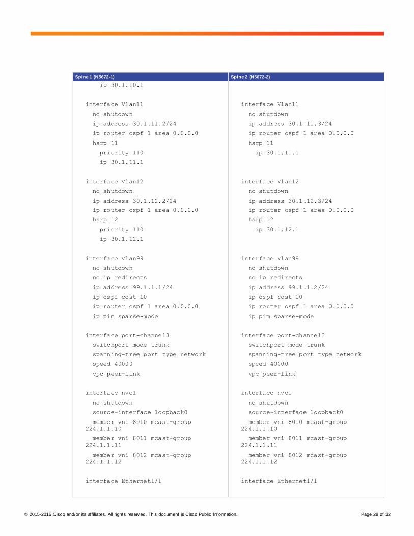
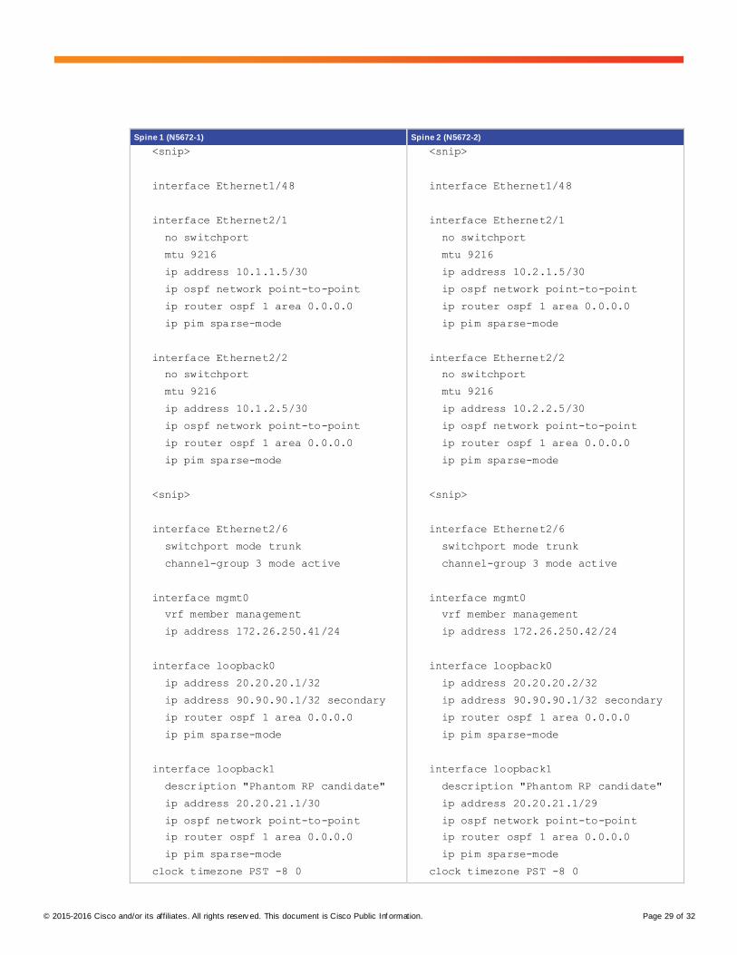
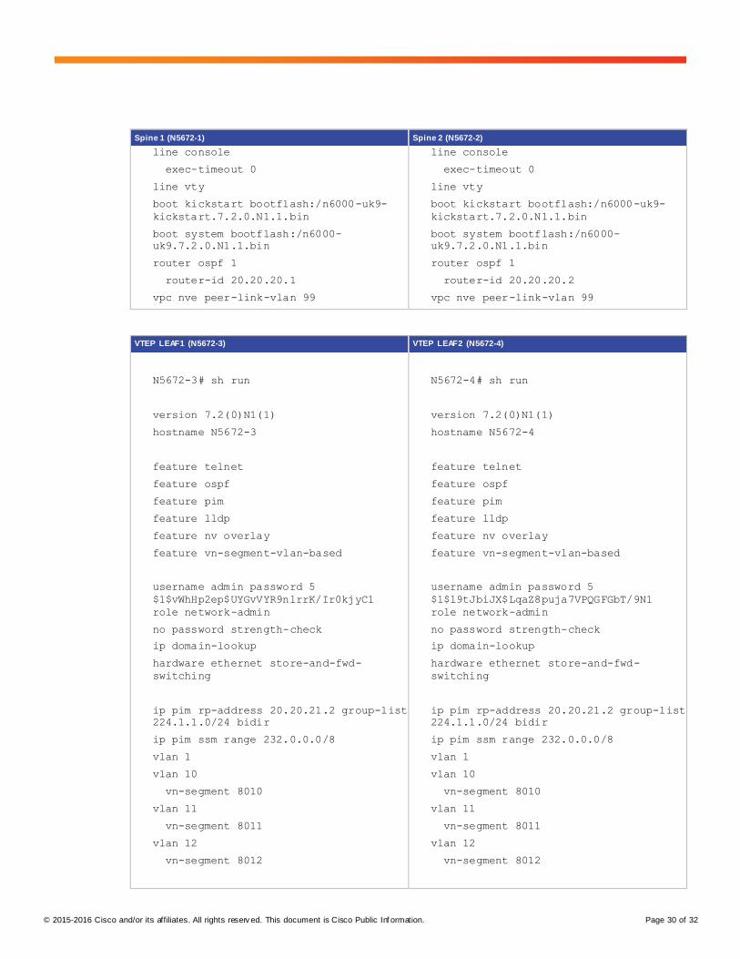
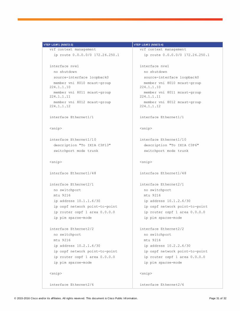
Appendix B: Centralized Layer 3 VXLAN Gateway Configuration on Nexus 5600
In VXLAN flood and learn mode, the recommended Layer 3 gateway design would be a pair of switches in VPC to
be the Layer 3 centralized gateway with FHRP (First Hop Redundancy Protocol) running on the SVIs. The pair of
VPC switches can be a pair of spine switches or a dedicated pair of leaf switches.
Appendix B presents a simple Centralized Layer 3 VXLAN Gateway Configuration example with VPC on spine
switches. This example uses two spine switches (N5672-1, N5672-2) and two leaf switches (N5672-3, N5672-4).
The two leaf switches (N5672-3, N5672-4) are Layer 2 VXLAN Gateways. The two Spine switches are configured
with VPC with HSRP as Layer 3 VXLAN Gateway. All VXLAN-to-VXLAN Routing and VXLAN-to-VLAN Routing are
done by the pair of VPC spine switches. Layer 3 Transport Underlay network is enabled with OSPF and PIM BIDIR
with Static Phantom RP for RP redundancy.
Configurations on switches:
Spine 1 (N5672-1) Spine 2 (N5672-2)
N5672-1# sh run
version 7.2(0)N1(1)
hostname N5672-1
feature telnet
cfs eth distribute
feature ospf
N5672-2# sh run
version 7.2(0)N1(1)
hostname N5672-2
feature telnet
cfs eth distribute
feature ospf
© 2015-2016 Cisco and/or its affiliates. All rights reserv ed. This document is Cisco Public Inf ormation. Page 27 of 32
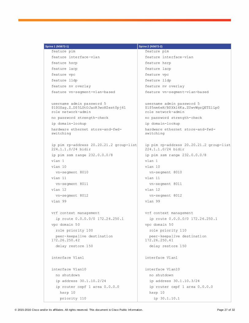
Spine 1 (N5672-1) Spine 2 (N5672-2)
feature pim
feature interface-vlan
feature hsrp
feature lacp
feature vpc
feature lldp
feature nv overlay
feature vn-segment-vlan-based
username admin password 5
$1$OSag.Z.D$5LStOJaoR3woHZest0pj61
role network-admin
no password strength-check
ip domain-lookup
hardware ethernet store-and-fwd-
switching
ip pim rp-address 20.20.21.2 group-list
224.1.1.0/24 bidir
ip pim ssm range 232.0.0.0/8
vlan 1
vlan 10
vn-segment 8010
vlan 11
vn-segment 8011
vlan 12
vn-segment 8012
vlan 99
vrf context management
ip route 0.0.0.0/0 172.26.250.1
vpc domain 50
role priority 100
peer-keepalive destination
172.26.250.42
delay restore 150
interface Vlan1
interface Vlan10
no shutdown
ip address 30.1.10.2/24
ip router ospf 1 area 0.0.0.0
hsrp 10
priority 110
feature pim
feature interface-vlan
feature hsrp
feature lacp
feature vpc
feature lldp
feature nv overlay
feature vn-segment-vlan-based
username admin password 5
$1$5nm6eH/B$Xkl6Ka.ZUwvWgzQETZlLp0
role network-admin
no password strength-check
ip domain-lookup
hardware ethernet store-and-fwd-
switching
ip pim rp-address 20.20.21.2 group-list
224.1.1.0/24 bidir
ip pim ssm range 232.0.0.0/8
vlan 1
vlan 10
vn-segment 8010
vlan 11
vn-segment 8011
vlan 12
vn-segment 8012
vlan 99
vrf context management
ip route 0.0.0.0/0 172.26.250.1
vpc domain 50
role priority 110
peer-keepalive destination
172.26.250.41
delay restore 150
interface Vlan1
interface Vlan10
no shutdown
ip address 30.1.10.3/24
ip router ospf 1 area 0.0.0.0
hsrp 10
ip 30.1.10.1
© 2015-2016 Cisco and/or its affiliates. All rights reserv ed. This document is Cisco Public Inf ormation. Page 28 of 32
Spine 1 (N5672-1) Spine 2 (N5672-2)
ip 30.1.10.1
interface Vlan11
no shutdown
ip address 30.1.11.2/24
ip router ospf 1 area 0.0.0.0
hsrp 11
priority 110
ip 30.1.11.1
interface Vlan12
no shutdown
ip address 30.1.12.2/24
ip router ospf 1 area 0.0.0.0
hsrp 12
priority 110
ip 30.1.12.1
interface Vlan99
no shutdown
no ip redirects
ip address 99.1.1.1/24
ip ospf cost 10
ip router ospf 1 area 0.0.0.0
ip pim sparse-mode
interface port-channel3
switchport mode trunk
spanning-tree port type network
speed 40000
vpc peer-link
interface nve1
no shutdown
source-interface loopback0
member vni 8010 mcast-group
224.1.1.10
member vni 8011 mcast-group
224.1.1.11
member vni 8012 mcast-group
224.1.1.12
interface Ethernet1/1
interface Vlan11
no shutdown
ip address 30.1.11.3/24
ip router ospf 1 area 0.0.0.0
hsrp 11
ip 30.1.11.1
interface Vlan12
no shutdown
ip address 30.1.12.3/24
ip router ospf 1 area 0.0.0.0
hsrp 12
ip 30.1.12.1
interface Vlan99
no shutdown
no ip redirects
ip address 99.1.1.2/24
ip ospf cost 10
ip router ospf 1 area 0.0.0.0
ip pim sparse-mode
interface port-channel3
switchport mode trunk
spanning-tree port type network
speed 40000
vpc peer-link
interface nve1
no shutdown
source-interface loopback0
member vni 8010 mcast-group
224.1.1.10
member vni 8011 mcast-group
224.1.1.11
member vni 8012 mcast-group
224.1.1.12
interface Ethernet1/1
© 2015-2016 Cisco and/or its affiliates. All rights reserv ed. This document is Cisco Public Inf ormation. Page 29 of 32
Spine 1 (N5672-1) Spine 2 (N5672-2)
<snip>
interface Ethernet1/48
interface Ethernet2/1
no switchport
mtu 9216
ip address 10.1.1.5/30
ip ospf network point-to-point
ip router ospf 1 area 0.0.0.0
ip pim sparse-mode
interface Ethernet2/2
no switchport
mtu 9216
ip address 10.1.2.5/30
ip ospf network point-to-point
ip router ospf 1 area 0.0.0.0
ip pim sparse-mode
<snip>
interface Ethernet2/6
switchport mode trunk
channel-group 3 mode active
interface mgmt0
vrf member management
ip address 172.26.250.41/24
interface loopback0
ip address 20.20.20.1/32
ip address 90.90.90.1/32 secondary
ip router ospf 1 area 0.0.0.0
ip pim sparse-mode
interface loopback1
description "Phantom RP candidate"
ip address 20.20.21.1/30
ip ospf network point-to-point
ip router ospf 1 area 0.0.0.0
ip pim sparse-mode
clock timezone PST -8 0
<snip>
interface Ethernet1/48
interface Ethernet2/1
no switchport
mtu 9216
ip address 10.2.1.5/30
ip ospf network point-to-point
ip router ospf 1 area 0.0.0.0
ip pim sparse-mode
interface Ethernet2/2
no switchport
mtu 9216
ip address 10.2.2.5/30
ip ospf network point-to-point
ip router ospf 1 area 0.0.0.0
ip pim sparse-mode
<snip>
interface Ethernet2/6
switchport mode trunk
channel-group 3 mode active
interface mgmt0
vrf member management
ip address 172.26.250.42/24
interface loopback0
ip address 20.20.20.2/32
ip address 90.90.90.1/32 secondary
ip router ospf 1 area 0.0.0.0
ip pim sparse-mode
interface loopback1
description "Phantom RP candidate"
ip address 20.20.21.1/29
ip ospf network point-to-point
ip router ospf 1 area 0.0.0.0
ip pim sparse-mode
clock timezone PST -8 0
© 2015-2016 Cisco and/or its affiliates. All rights reserv ed. This document is Cisco Public Inf ormation. Page 30 of 32
Spine 1 (N5672-1) Spine 2 (N5672-2)
line console
exec-timeout 0
line vty
boot kickstart bootflash:/n6000-uk9-
kickstart.7.2.0.N1.1.bin
boot system bootflash:/n6000-
uk9.7.2.0.N1.1.bin
router ospf 1
router-id 20.20.20.1
vpc nve peer-link-vlan 99
line console
exec-timeout 0
line vty
boot kickstart bootflash:/n6000-uk9-
kickstart.7.2.0.N1.1.bin
boot system bootflash:/n6000-
uk9.7.2.0.N1.1.bin
router ospf 1
router-id 20.20.20.2
vpc nve peer-link-vlan 99
VTEP LEAF1 (N5672-3) VTEP LEAF2 (N5672-4)
N5672-3# sh run
version 7.2(0)N1(1)
hostname N5672-3
feature telnet
feature ospf
feature pim
feature lldp
feature nv overlay
feature vn-segment-vlan-based
username admin password 5
$1$vWhHp2ep$UYGvVYR9nlrrK/Ir0kjyC1
role network-admin
no password strength-check
ip domain-lookup
hardware ethernet store-and-fwd-
switching
ip pim rp-address 20.20.21.2 group-list
224.1.1.0/24 bidir
ip pim ssm range 232.0.0.0/8
vlan 1
vlan 10
vn-segment 8010
vlan 11
vn-segment 8011
vlan 12
vn-segment 8012
N5672-4# sh run
version 7.2(0)N1(1)
hostname N5672-4
feature telnet
feature ospf
feature pim
feature lldp
feature nv overlay
feature vn-segment-vlan-based
username admin password 5
$1$l9tJbiJX$LqaZ8puja7VPQGFGbT/9N1
role network-admin
no password strength-check
ip domain-lookup
hardware ethernet store-and-fwd-
switching
ip pim rp-address 20.20.21.2 group-list
224.1.1.0/24 bidir
ip pim ssm range 232.0.0.0/8
vlan 1
vlan 10
vn-segment 8010
vlan 11
vn-segment 8011
vlan 12
vn-segment 8012
© 2015-2016 Cisco and/or its affiliates. All rights reserv ed. This document is Cisco Public Inf ormation. Page 31 of 32
VTEP LEAF1 (N5672-3) VTEP LEAF2 (N5672-4)
vrf context management
ip route 0.0.0.0/0 172.26.250.1
interface nve1
no shutdown
source-interface loopback0
member vni 8010 mcast-group
224.1.1.10
member vni 8011 mcast-group
224.1.1.11
member vni 8012 mcast-group
224.1.1.12
interface Ethernet1/1
<snip>
interface Ethernet1/10
description "To IXIA C3P13"
switchport mode trunk
<snip>
interface Ethernet1/48
interface Ethernet2/1
no switchport
mtu 9216
ip address 10.1.1.6/30
ip ospf network point-to-point
ip router ospf 1 area 0.0.0.0
ip pim sparse-mode
interface Ethernet2/2
no switchport
mtu 9216
ip address 10.2.1.6/30
ip ospf network point-to-point
ip router ospf 1 area 0.0.0.0
ip pim sparse-mode
<snip>
interface Ethernet2/6
vrf context management
ip route 0.0.0.0/0 172.26.250.1
interface nve1
no shutdown
source-interface loopback0
member vni 8010 mcast-group
224.1.1.10
member vni 8011 mcast-group
224.1.1.11
member vni 8012 mcast-group
224.1.1.12
interface Ethernet1/1
<snip>
interface Ethernet1/10
description "To IXIA C3P6"
switchport mode trunk
<snip>
interface Ethernet1/48
interface Ethernet2/1
no switchport
mtu 9216
ip address 10.1.2.6/30
ip ospf network point-to-point
ip router ospf 1 area 0.0.0.0
ip pim sparse-mode
interface Ethernet2/2
no switchport
mtu 9216
ip address 10.2.2.6/30
ip ospf network point-to-point
ip router ospf 1 area 0.0.0.0
ip pim sparse-mode
<snip>
interface Ethernet2/6
© 2015-2016 Cisco and/or its affiliates. All rights reserv ed. This document is Cisco Public Inf ormation. Page 32 of 32
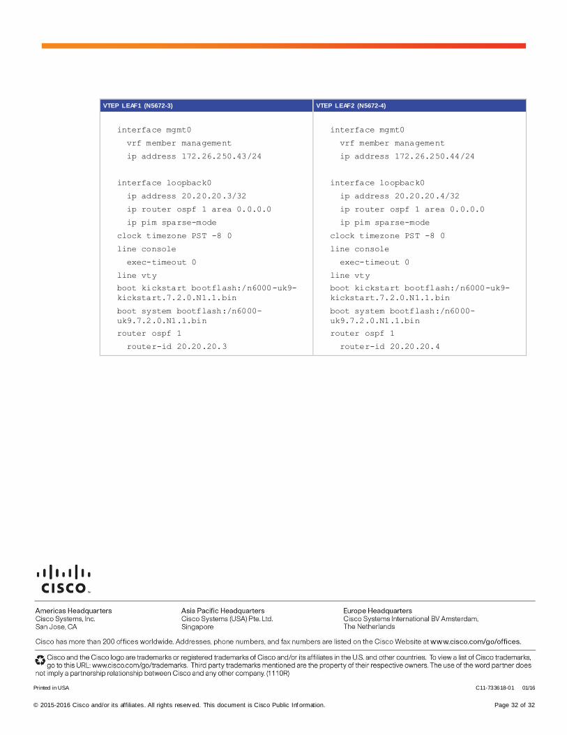
VTEP LEAF1 (N5672-3) VTEP LEAF2 (N5672-4)
interface mgmt0
vrf member management
ip address 172.26.250.43/24
interface loopback0
ip address 20.20.20.3/32
ip router ospf 1 area 0.0.0.0
ip pim sparse-mode
clock timezone PST -8 0
line console
exec-timeout 0
line vty
boot kickstart bootflash:/n6000-uk9-
kickstart.7.2.0.N1.1.bin
boot system bootflash:/n6000-
uk9.7.2.0.N1.1.bin
router ospf 1
router-id 20.20.20.3
interface mgmt0
vrf member management
ip address 172.26.250.44/24
interface loopback0
ip address 20.20.20.4/32
ip router ospf 1 area 0.0.0.0
ip pim sparse-mode
clock timezone PST -8 0
line console
exec-timeout 0
line vty
boot kickstart bootflash:/n6000-uk9-
kickstart.7.2.0.N1.1.bin
boot system bootflash:/n6000-
uk9.7.2.0.N1.1.bin
router ospf 1
router-id 20.20.20.4
Printed in USA C11-733618-01 01/16