Embed Size (px)
Citation preview
Virtual Environment for Testing Software-Defined NetworkingSolutions for Scientific Workflows
Qiang Liu, Nageswara S. V. Rao, Satyabrata SenComputational Sciences and Engineering Division
Oak Ridge National LaboratoryOak Ridge, TN, USA
{liuq1,raons,sens}@ornl.gov
Bradley W. Settlemyer, Hsing-Bung ChenHigh Performance Computing Division
Los Alamos National LaboratoryLos Alamos, NM, USA{bws,hbchen}@lanl.gov
Joshua M. Boley, Rajkumar KettimuthuMathematics and Computer Science Division
Argonne National LaboratoryArgonne, IL, USA
{jboley,kettimut}@anl.gov
Dimitrios KatramatosComputational Science InitiativeBrookhaven National Laboratory
Upton, NY, [email protected]
ABSTRACTRecent developments in software-defined infrastructures promisethat scientific workflows utilizing supercomputers, instruments,and storage systems will be dynamically composed and orches-trated using software at unprecedented speed and scale in the nearfuture. Testing of the underlying networking software, particu-larly during initial exploratory stages, remains a challenge dueto potential disruptions, and resource allocation and coordinationneeded over the multi-domain physical infrastructure. To overcomethese challenges, we develop the Virtual Science Network Envi-ronment (VSNE) that emulates the multi-site host, storage, andnetwork infrastructure using Virtual Machines (VMs), wherein theproduction and nascent software can be tested. Within each VM,which represents a site, the hosts and local-area networks are em-ulated using Mininet, and the Software-Defined Network (SDN)controllers and service daemon codes are natively run to supportdynamic provisioning of network connections. Additionally, Lustrefilesystem support at the sites and an emulation of the long-haulnetwork using Mininet, are provided using separate VMs. As casestudies, we describe Lustre file transfers using XDD, Red5 streamingservice demonstration, and an emulated experiment with remotemonitoring and steering modules, all supported over dynamicallyconfigured connections using SDN controllers.
CCS CONCEPTS• Networks→ Network services; Network experimentation;
KEYWORDSSoftware-defined infrastructure, software-defined networking, vir-tual science network environment, scientific workflows.
Permission to make digital or hard copies of all or part of this work for personal orclassroom use is granted without fee provided that copies are not made or distributedfor profit or commercial advantage and that copies bear this notice and the full citationon the first page. Copyrights for components of this work owned by others than ACMmust be honored. Abstracting with credit is permitted. To copy otherwise, or republish,to post on servers or to redistribute to lists, requires prior specific permission and/or afee. Request permissions from [email protected]’18, June 11, 2018, Tempe, AZ, USA© 2018 Association for Computing Machinery.ACM ISBN 978-1-4503-5862-0/18/06. . . $15.00https://doi.org/10.1145/3217197.3217202
ACM Reference Format:Qiang Liu, Nageswara S. V. Rao, Satyabrata Sen, Bradley W. Settlemyer,Hsing-Bung Chen, Joshua M. Boley, Rajkumar Kettimuthu, and DimitriosKatramatos. 2018. Virtual Environment for Testing Software-Defined Net-working Solutions for Scientific Workflows. In AI-Science’18: AutonomousInfrastructure for Science, June 11, 2018, Tempe, AZ, USA. ACM, New York,NY, USA, 8 pages. https://doi.org/10.1145/3217197.3217202
1 INTRODUCTIONScientific workflows are supported by an infrastructure of scien-tific instruments, supercomputers, storage systems, and customvisualization facilities [1] that are located at geographically dis-persed sites and are connected over high-performance networks.To accomplish extreme-scale science by utilizing such an infras-tructure, scientific workflows often require large data transfers andremote monitoring, streaming, and steering operations. These tasksin turn require dedicated high-capacity, low-latency, and low-jitternetwork connections during specified periods. Such connectionsare typically composed of both site Local-Area Network (LAN)segments and Wide-Area Network (WAN) connections over a dedi-cated high-capacity network infrastructure for data flows, as wellas a persistent shared network among these sites for control traffic.Currently, the dedicated connections are provisioned manually bysite and WAN operators, with typical lead times of days or longer.However, recent developments in Software-Defined Infrastructure(SDI) promise advanced capabilities such that end-systems and net-work paths can be composed and orchestrated entirely by softwareat unprecedented speed and scale. In particular, Software-DefinedNetworking (SDN) technologies [9, 25] enable automatic provision-ing of these dedicated connections with much faster setup times,for example, within a few seconds.
The development of networking software modules for scientificworkflows and an assessment of their impacts often require installa-tion and evaluation of untested technologies. Performing these tasksover production-grade physical infrastructure remains extremelychallenging, since it requires substantial resource allocations andoften labor-intensive coordinations among site and network oper-ations teams. For early functionality tests and proof-of-principledemonstrations, such expenses are not justified, particularly, if the
infrastructure is taken away from normal production use. Addition-ally, SDN codes in the early developmental stages can be disruptivesince they can degrade the network, and in extreme cases, can floodor even crash significant portions of it. To overcome these chal-lenges, we develop the Virtual Science Network Environment (VSNE)that emulates the host, storage, and network infrastructure of mul-tiple sites using Virtual Machines (VMs). A site is represented by aVM, wherein the hosts and LANs are emulated using Mininet, andSDN controllers and site service daemons are executed natively tosupport dynamic provisioning of network connections. In addition,Lustre filesystems are supported at these sites using a server VM,and the long-haul network connections are emulated using Minineton WAN VM. Applications such as file transfer, streaming, andexperiment steering, can be installed on VMs and made availableto all emulated site hosts.
Thus, without the expensive physical infrastructure, VSNE canbe run on a workstation to develop and test various software com-ponents. In collaborative projects, VSNE can be replicated at allparticipating sites so that their respective solutions can be inde-pendently developed and tested, and uploaded to other sites. Uponmaturity, these codes can be rolled into production physical in-frastructure. Therefore, VSNE provides several advantages: (i) itenables early testing of workflow components, such as SDN scriptsand applications, which could be potentially disruptive; (ii) it doesnot require the expenses of multi-site collaboration and physicalresources; and (iii) solutions can be independently and concurrentlydeveloped before or while the physical infrastructure is being built.In particular, the VSNE described in this paper emulates the infras-tructure that is currently being built to span four Department ofEnergy (DOE) national laboratories, namely, Argonne National Lab-oratory (ANL), Brookhaven National Laboratory (BNL), Los AlamosNational Laboratory (LANL), and Oak Ridge National Laboratory(ORNL).
In addition to developing VSNE, we also present SDN codes toset up dedicated connections among the sites using a network ofsite-service daemons that are connected over the shared network.These daemons utilize custom scripts and northbound controllerinterfaces to coordinate the setup and teardown of dedicated net-work links. Once a connection request is received from the users, asite daemon translates and communicates subsequent requests toother site- and WAN-daemons, which are in turn translated intocommands for setting up the site network elements. We have con-sidered SDN solutions using custom dpctl scripts and open-sourcecontrollers including OpenDaylight (ODL) [14], Floodlight [7], andONOS [15] in our previous study [19, 20] and investigated the TCPtransport dynamics with these controllers.
We describe three scientific use cases using VSNE with dedi-cated connections provisioned using the above-mentioned SDNsolutions. First, we illustrate Lustre file transfers using XDD [24]over dynamically provisioned connections. Second, we demonstratethe use of Red5 framework [21] for data-streaming applications,which shows its applicability to scientific workflows. Third, wepresent an emulated experiment in which remote monitoring andparameter steering capabilities are demonstrated. These use casesillustrate that such workflows are compatible with dynamicallySDN-provisioned network paths, so that further development anddetailed performance testing can be carried out, possibly, over the
physical infrastructure. In addition to establishing the utility ofVSNE for functionality tests, these tests also reveal some limita-tions in accurately emulating the network transport dynamics.
The organization of this paper is as follows. In Section 2, we pro-vide two examples of scientific workflows to motivate the neededSDN capabilities. In Section 3, we describe VSNE in detail, includingits capabilities, a site-service daemon framework that connects theelements together, and its implementation using VMs and Mininet.In Section 4, we present the use cases of XDD file transfers, Red5streaming framework, and remote instrument monitoring and steer-ing. The paper concludes in Section 5.
2 SCIENCE SCENARIOSScientific workflows are realized by composing and automatingcomplex scientific applications to enable collaborations among re-searchers in many disciplines, such as biology, astronomy, environ-mental science, materials science, nuclear science, among others [1].By using flexible high-level abstraction languages, these workflowscan mask the complexity of execution infrastructure, and allow sci-entists to execute simulations on remote systems, retrieve data froman instrument or database, process the data, and run data analysistools, while automating data movement between various stages ofthe workflow processing [5]. We present below a brief overviewof two representative categories of scientific workflows, and dis-cuss the challenges associated with state-of-the-art networking andservices.
2.1 Scientific Workflow DriversA. Workflows for Near-Real-Time Computations: Data generatedat an instrument system, during or after the experiments, are of-ten transported to a remote supercomputer site for near-real-timeanalysis and computation. For example, in cosmology, the rawdata generated by the Palomar Transient Factory (PTF) [10] surveyare processed by a near-real-time computational code at a remotenational laboratory to identify optical transients within minutesof images being taken. Similarly, in material science, to facilitatenear-real-time analysis of organic photovoltaics (OPV) using x-rayscattering, Lawrence Berkeley National Laboratory (LBNL) Ad-vanced Light Source (ALS) data need to be moved to ORNL becausecurrently only Titan has the computational capability to run therequired analysis tool HipGISAXS [2].
B. Workflows for Dynamic Monitoring and Control: Data gener-ated from a running computation and/or an instrument often needto be dynamically monitored at local or remote facilities to under-stand whether the simulation/experiment is functioning properly.Analysis and control of these intermediate datasets are critical todrive the next simulation/experiment configurations at various sci-ence facilities [1], including ALS, Spallation Neutron Source (SNS),Large Synoptic Survey Telescope (LSST), and others.
2.2 State-of-the-Art Approaches andChallenges
Both workflows mentioned above require data movement, stream-ing, and control operations to be supported over wide-area net-works, in particular, by on-demand/advance-reserved dedicated
connections with high bandwidth and low jitter. Currently, custom-designed science network connections are typically composed andconfigured by teams of experts. For example, LAN andWAN connec-tions are set up by network engineers, and dedicated I/O resourcesand host systems are configured by systems administrators. Multi-ple valuable resources are often over-provisioned to meet the peaktransient needs. Thus, although highly desired, many promisingcapabilities, including on-demand computation/instrument moni-toring, interactive steering, etc., are not implemented. In the future,the hosts, storage, and networks are expected to become increas-ingly sophisticated, and the number of possible combinations ofparameters to be optimized for a complex scientific workflow willincrease exponentially, and will be beyond the limits of manualoperations. Recent developments in SDN and related technolo-gies [9, 11] hold an enormous promise in developing fast automaticprovisioning of the underlying network paths. However, the testingof new components of workflows, such as XDD optimized for Lus-tre and custom Red5 streaming apps for science, requires multi-sitenetworked infrastructure, and our VM-based VSNE provides analternative development environment for them.
Moreover, it is to be noted that the network flows associatedwith science applications represent a different set of challengesfrom the data center and cloud environments, where the currentSDN technologies are being developed. The predominant feature ofscientific workflows is that they are small in numbers originatingfrom known sites, and they involve dedicated, precision flows overmulti-domain wide/local/storage area networks; these features aresupported in our VSNE using VMs and Mininet. In contrast toother VM-based projects, such as OpenGENI [16] for networkedOpenStack components, Chameleon [4] for cloud infrastructure,Jetstream [8] incorporating both, ViNO orchestration service [3]for creating network topologies, and DOT [22] for low cost andscalable network emulation, our VSNE is specifically tailored toscience environments by using Mininet to emulate site hosts andnetworks, with additional support for Lustre filesystem and a suiteof controllers, as described in the next section.
3 VIRTUAL SCIENCE NETWORKENVIRONMENT
In this section, we provide a detailed description of the virtual sci-ence network environment (VSNE), including its functionality andimplementation. Particularly, we highlight its capability to emulatethe network and storage infrastructure in real-world scientific work-flow applications. The site-service daemon framework is shownto facilitate persistent control-plane connections. Virtual machineconfigurations, Mininet network topologies, and the interconnectedsite service daemon framework are presented for a four-site VSNE.
3.1 VSNE CapabilitiesOur VSNE enables early testing of SDN solutions (some of which arepotentially disruptive) before or while the physical infrastructureis being built. In particular, a number of virtual site hosts, switches,and network links are created on a virtual machine (VM) wherecustom applications and filesystems are also installed and madeavailable to every virtual site host, since the latter can inherit theexecution environment from the site VM where it resides. Our
default WAN
site daemon 1
controller 1
switch switch
site network 1
site daemon 2
controller 2
switch switch
site network 2
site daemon n
controller n
switch switch
site network n
dedicated WAN
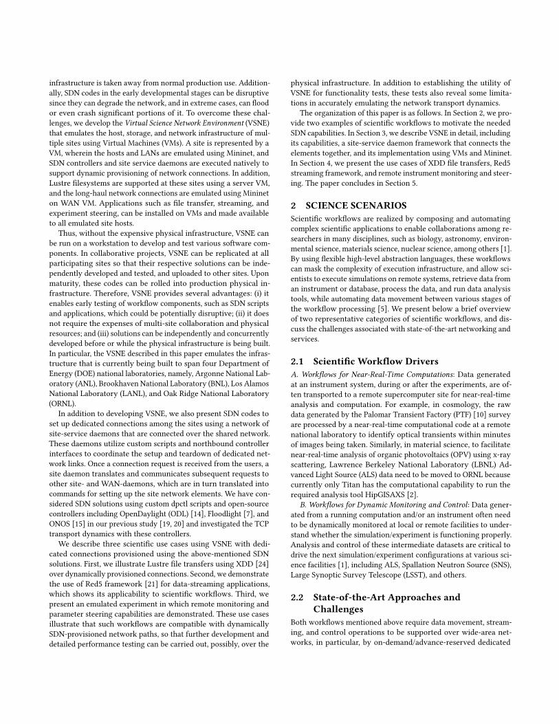
Figure 1: Framework of interconnected site daemons
functionality testing examples to be presented in Section 4 arerun from the perspective of a site host. For storage, we supportthe Lustre filesystem [12] on the site hosts by utilizing a Lustreserver on a dedicated VM. Site hosts run Lustre clients to mountthe filesystem and utilize assigned sub-directories for individualsites. The Lustre VM is connected to site VMs over an internalnetwork which represents the site storage network. Each site VMcontains hosts and LANs emulated using Mininet, and the site VMsare interconnected using a WAN VM. SDN controllers and servicedaemons support dynamic provisioning of network connections,whose details are discussed below.
3.2 Site Service Daemon FrameworkIn our SDN solution, a set of site-service daemons provide connectiv-ity among the sites over the default IP network. These site-servicedaemons maintain persistent connectivity among themselves andalso with the local site-controllers, switches, and users, as shown inFigure 1. The local site-service daemon receives connection requests(setup/teardown) from local users, automated workflow agents, orremote site-service daemons. In response, it invokes custom scriptsto set up or tear down connections within the site, and generatesspecifications for WAN and remote site connections, and communi-cates them to WAN and remote site-service daemons. We show anillustration of two-site path setup in Figure 2. While the SDN con-trollers communicate with switches to install, query, and delete flowentries on their southbound interfaces, the site-service daemonstalk with SDN controllers via the northbound interface. Examplesof using these service daemons are shown in Section 4.
3.3 Virtual Machine ConfigurationsWe use a total of six VMs, four of which represent the sites, namely,ANL, BNL, LANL and ORNL, and a fifth VM emulates the dedi-cated ESnet [6] WAN connections among these sites, as shown inFigure 3. An additional VM provides the Lustre filesystem to bemounted onto all four sites1. The VMs run under the VirtualBox 5.1environment on a Linux host with RHEL 7.2 kernel. For each siteVM, three interfaces are enabled – Network Address Translation(NAT) interface and two internal interfaces. The host OS re-routs
1Realistically each site would have its own Lustre filesystem; however, use of a singleLustre VM to be mounted to the site VMs can reduce the total number of VMs runningin VirtualBox.
persistent network
site daemon
controller
switch switch
site daemon
controller
switch switch end
system end
system
dynamic data-path over high-performance
network infrastructure
Figure 2: Illustration of path establishment between twosites
ANL-VM BNL-VM
LANL-VM ORNL-VM
WAN-VM
LustreVM
Lustre
Lustre
Lustre
Lustre
Figure 3: Site connections
S1
h1 h2
S2 daemon
controller
mininet VM
data-plane
control-plane
To WAN
Figure 4: Site VM configuration
and re-sends all the data sent from the guest VM via the NAT inter-face, the control-plane communications among all the sites usingthe site daemon codes are executed via one internal interface, andthe dedicated data-plane connection among the site VMs and WANVM is implemented via the other internal interface.
3.4 Network EmulationWe use Mininet [13] to create custom parameterized topologies onsite and WAN VMs using Python code. Figure 4 illustrates the con-figuration on any of the four site VMs. We create two virtual hostsh1 and h2 that are connected to a virtual switch s2; then, another
daemon controller
mininet
WAN-VM
data-plane control-plane
ANL border
ORNL border
LANL border
BNL border
to ANL VM
to LANL VM
to BNL VM
to ORNL VM
to daemons
Figure 5: WAN VM configuration
“gateway” switch s1 serves to link s2 and the outside world. Both s1and s2 are Open vSwitches whose flows can be dynamically orches-trated as needed; these switches represent the deployed OpenFlowhardware switches, and in particular, they support both dpctl andopen-source controllers so that VSNE codes can be transferred tophysical networks. Also shown as components on the site VM inFigure 4 are an SDN controller and a site-service daemon, wherethe latter is used for communications of control-plane messageswith other sites.
On the WAN VM, four Open vSwitches are created in Mininetthat emulate the physical circuits – for example, similar to those inOSCARS [17] – required to access the long-haul links among thesites. Figure 5 illustrates both the data-plane connections amongthe switches and to the outside world, and the control-plane connec-tions involving the controller and/or the WAN daemon. In addition,we incorporate the actual long-haul link latency between physicalsites in the Mininet environment, by imposing various delay param-eters, between the “border router” site-pairs in the Python script.For instance, the one-way latency between ANL and ORNL is setto be 6 ms. A simple rate control mechanism is also implementedin the same script where the maximum link-bandwidth is set to be20 Mbps.
3.5 Path Request via Science User WebInterface
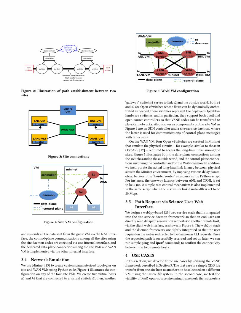
We design a web2py-based [23] web service stack that is integratedinto the site-service daemon framework so that an end user candirectly send datapath reservation requests (to another remote host)via the client web interface, as shown in Figure 6. The web2py stackand the daemon framework are tightly integrated so that the userrequest on theweb is redirected to the daemon as CLI requests. Oncethe requested path is successfully reserved and set up later, we canrun simple ping and iperf commands to confirm the connectivitybetween the two remote hosts.
4 USE CASESIn this section, we develop three use cases by utilizing the VSNEframework described in Section 3. The first case is a simple XDD filetransfer from one site host to another site host located on a differentVM, using the Lustre filesystem. In the second case, we test theviability of Red5 open-source streaming framework that supports a
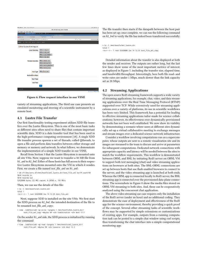
Figure 6: Flow request interface in our VSNE
variety of streaming applications. The third use case presents anemulated monitoring and steering of a scientific instrument by aremote host.
4.1 Lustre File TransferOur first functionality testing experiment utilizes XDD file trans-fers over the Lustre filesystem. This is one of the most basic tasksas different sites often need to share files that contain importantscientific data. XDD is a data transfer tool that has been used inthe high-performance computing environment [18]. A single XDDfile transfer process spawns a set of threads, called Qthreads, toopen a file and perform data transfers between either storage andmemory or memory and network. In what follows, we demonstratethe implementation of a simple XDD transfer in our VSNE.
Recall from Section 3 that the Lustre filesystem is mounted ontoall site VMs. Now, suppose we want to transfer a 50 MB file fromh1_anl toh2_bnl . Either of these hosts has full access to their respec-tive Lustre filesystems mounted onto the VM in which it resides.First, we create a file named test_file_anl on h1_anl :> dd if=/dev/zero of=/mnt/knotfs/anl_lustre_dir/test_file_anl bs=1M count=50
50+0 records in
50+0 records out
52428800 bytes (52 MB) copied, 0.28589 s, 183 MB/s
Then, we can see the details of this file:> ls -l /mnt/knotfs/anl_lustre_dir
total 1
-rw-r--r-- 1 root 52428800 Jun 14 12:29 test_file_anl
Next, suppose XDD is installed on the site VMs. We first startthe XDD process on h2_bnl , the intended destination of the file tobe renamed test_file_anl_copy:> time ./xdd/bin/xdd -op write -targets 1 /mnt/knotfs/bnl_lustre_dir/
test_file_anl_copy -mbytes 50 -e2e isdestination -e2e dest 12.2
On the senderh1_anl side, the XDD process is initialized by runningthe command> time ./xdd/bin/xdd -op read -targets 1 /mnt/knotfs/anl_lustre_dir/
test_file_anl -mbytes 50 -e2e issource -e2e dest 12.2
The file-transfer then starts if the datapath between the host pairhas been set up; once complete, we can run the following commandon h2_bnl to verify the file has indeed been transferred successfully:
> ls -l /mnt/knotfs/bnl_lustre_dir
total 1
-rw-r--r-- 1 root 52428800 Jun 14 12:33 test_file_anl_copy
Detailed information about the transfer is also displayed at boththe sender and receiver. The outputs are rather long, but the lastfew lines show some of the most important metrics of interest,as displayed in Figure 7, including the transfer size, elapsed time,and bandwidth/throughput. Interestingly, here both file read- andwrite-rates are under 1 Mbps, much slower than the link capacityset as 20 Mbps.
4.2 Streaming ApplicationsThe open source Red5 streaming framework supports a wide varietyof streaming applications, for example, chat, video, and data stream-ing applications over the Real Time Messaging Protocol (RTMP)supported over TCP. While extensively used for streaming appli-cations over a variety of platforms, its use in scientific workflowshas been very limited. This framework has a potential for leadingto effective streaming applications tailor-made for science collab-orations; however, its effectiveness over dynamically provisionednetworks has not been well established. We now show its viabilityby demonstrating a scenario where users at different sites dynami-cally set-up a virtual collaborative meeting to exchange messagesand stream images over a dedicated science network infrastructure.
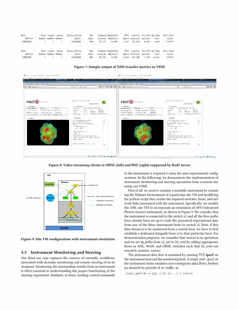
Consider a workflow involving computations run on a supercom-puter, whose outputs are sent to a remote visualization site and itsimages are streamed to the team to discuss and arrive at parametersfor subsequent computations. Dedicated network connections withappropriate capacity and latency will be needed between the sites tomatch the workflow requirements. This workflow is demonstratedbetween ORNL and BNL by initiating Red5 server on ORNL VMto support both text messaging (chat) and video streaming applica-tions on browsers at both sites. The BNL-ORNL connections areset up between hosts that use flash-enabled browsers to connect tothe server, and the video streaming app is launched at both ends.Whereas the ORNL app is connected locally to Red5 server, the BNLstreaming app is connected over the provisioned data-plane connec-tions. The screenshots in Figure 8 show the media files stored onORNL VM streaming to both sites. And, these can be cooperativelyanalyzed using the concurrent chat application.
The above video streaming use case requires only the installationof the Red5 server (under an hour) and no additional coding. Theydemonstrate the ease of deployment and effectiveness of the Red5app for the science environment, thereby providing a quick proofof the concept. Several other streaming tasks of scientific work-flows may be supported by simple extensions or customizationsof existing apps. For example, outputs from a running computa-tion task can be posted to a simple chat window using curl scripts,thus transforming the chat interface into a simple computationalmonitoring app.
What Pass Target Queue Bytes_Xfered Ops Elapsed Bandwidth IOPS Latency Pct_CPU Op_Type Xfer_Size
UNITS>> Number Number Number Bytes #ops seconds MBytes/s Ops/s millisec percent text bytes
COMBINED 1 1 1 52428800 400 55.319 0.948 7.231 138.298 0.542 read 131072
What Pass Target Queue Bytes_Xfered Ops Elapsed Bandwidth IOPS Latency Pct_CPU Op_Type Xfer_Size
UNITS>> Number Number Number Bytes #ops seconds MBytes/s Ops/s millisec percent text bytes
COMBINED 1 1 1 52428800 400 58.552 0.895 6.832 146.380 1.349 write 131072
Figure 7: Sample output of XDD transfer metrics in VSNE
Figure 8: Video streaming clients at ORNL (left) and BNL (right) supported by Red5 server
Figure 9: Site VM configuration with instrument emulation
4.3 Instrument Monitoring and SteeringOur third use case captures the essence of scientific workflowsassociated with dynamic monitoring and remote steering of an in-strument. Monitoring the intermediate results from an instrumentis often essential to understanding the proper functioning of therunning experiment. Similarly, at times, sending control commands
to the instrument is required to steer the next experimental config-urations. In the following, we demonstrate the implementation ofinstrument monitoring and steering operations from a remote siteusing our VSNE.
First of all, we need to emulate a scientific instrument by extend-ing the Mininet environment of a particular site VM and modifyingthe python script that creates the required switches, hosts, and net-work links associated with the instrument. Specifically, we modifythe ANL site VM to incorporate an emulation of APS (AdvancedPhoton Source) instrument, as shown in Figure 9. We consider thatthe instrument is connected to the switch s2, and all the flow-pathshave already been set up to route the generated experimental datafrom any of the three instrument hosts to switch s2. Now, if thisdata stream is to be monitored from a remote host, we have to firstestablish a dedicated datapath from s2 to that particular host. Fordemonstration purposes, we consider that instru1 is in operation,and we set up paths from s2_anl to h2_ornl by adding appropriateflows in ANL, WAN, and ORNL switches such that h2_ornl canremotely monitor instru1.
The instrument data flow is emulated by running TCP iperf onthe instrument host and themonitoring host. A script, instr_iperf, onthe instrument hosts emulates non-contiguous data flows, broken(as desired) by periods of no traffic, as./instr_iperf.sh -c [ip] -i [i1 i2 ...] -t [intrv]
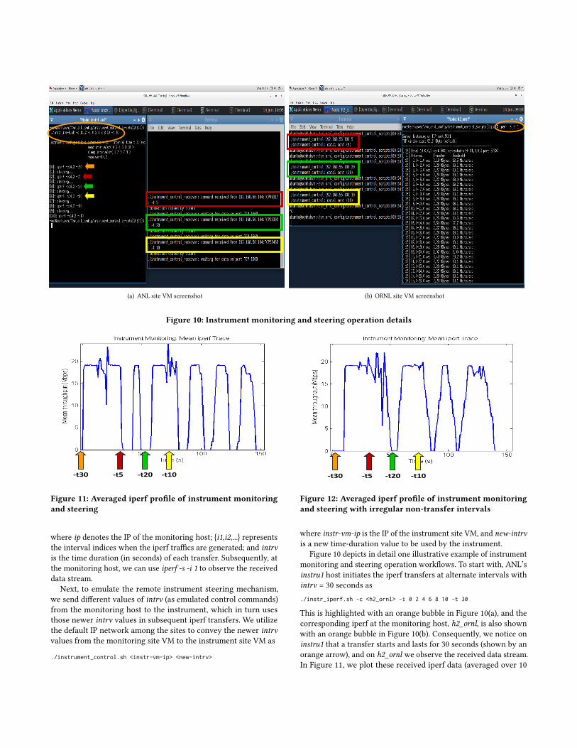
(a) ANL site VM screenshot (b) ORNL site VM screenshot
Figure 10: Instrument monitoring and steering operation details
-t30 -t5 -t20 -t10
Figure 11: Averaged iperf profile of instrument monitoringand steering
where ip denotes the IP of the monitoring host; {i1,i2,...} representsthe interval indices when the iperf traffics are generated; and intrvis the time duration (in seconds) of each transfer. Subsequently, atthe monitoring host, we can use iperf -s -i 1 to observe the receiveddata stream.
Next, to emulate the remote instrument steering mechanism,we send different values of intrv (as emulated control commands)from the monitoring host to the instrument, which in turn usesthose newer intrv values in subsequent iperf transfers. We utilizethe default IP network among the sites to convey the newer intrvvalues from the monitoring site VM to the instrument site VM as
./instrument_control.sh <instr-vm-ip> <new-intrv>
-t30 -t5 -t20 -t10
Figure 12: Averaged iperf profile of instrument monitoringand steering with irregular non-transfer intervals
where instr-vm-ip is the IP of the instrument site VM, and new-intrvis a new time-duration value to be used by the instrument.
Figure 10 depicts in detail one illustrative example of instrumentmonitoring and steering operation workflows. To start with, ANL’sinstru1 host initiates the iperf transfers at alternate intervals withintrv = 30 seconds as./instr_iperf.sh -c <h2_ornl> -i 0 2 4 6 8 10 -t 30
This is highlighted with an orange bubble in Figure 10(a), and thecorresponding iperf at the monitoring host, h2_ornl, is also shownwith an orange bubble in Figure 10(b). Consequently, we notice oninstru1 that a transfer starts and lasts for 30 seconds (shown by anorange arrow), and on h2_ornl we observe the received data stream.In Figure 11, we plot these received iperf data (averaged over 10
repetitive runs) as a function of time, and an orange arrow with-t30 indicates the specified time duration value.
While this first iperf transfer is ongoing, the monitoring hostdecides to send a control command to the instrument site for chang-ing the time-duration value to 5 seconds. This is communicatedfrom the ORNL site VM as./instrument_control.sh <ANL-site-vm-ip> 5
This is marked by a red box in Figure 10(b), and the correspondingacknowledgment at the ANL site VM is also marked by a red boxin Figure 10(a). In Figure 11, we use a red arrow to mark the timeinstance of this new control command with -t5. As a consequence,in the next transfer interval, instru1 starts a new iperf transfer thatlasts only 5 seconds, which is evident from a thinner profile of iperftransfer in Figure 11.
We continue this monitoring and steering procedure by sendingtwo more control commands for modifying the time-duration pa-rameter to 20 and 10 seconds, which are respectively indicated bygreen and yellow boxes/arrows in Figures 10 and 11. Subsequentiperf transfers from instru1 show that these steering parametersare correctly received and used (see green and yellow arrows inFigure 10(a)). The averaged iperf trace in Figure 11 also confirmsthe proper use of the most-recent time-duration parameter in thefollowing iperf transfers. As no further change is made to the time-duration value after -t10, each of the last three iperf transfers con-tinues for about 10 seconds (see Figures 10(a) and 11).
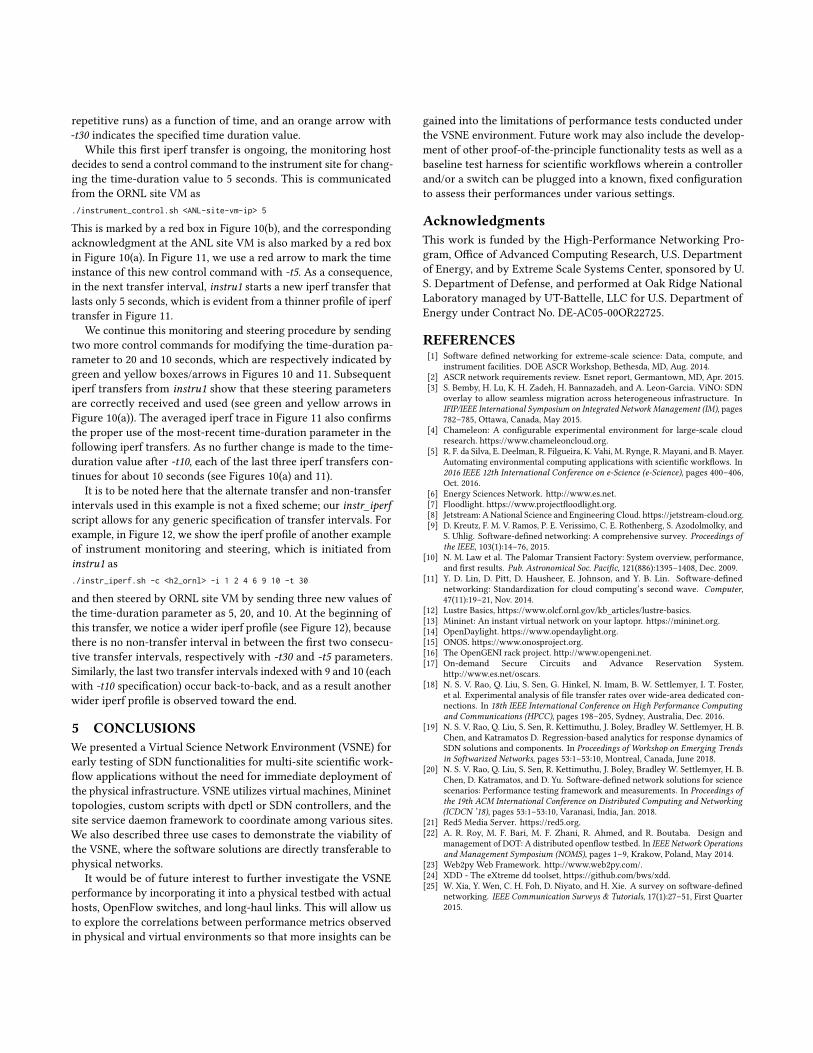
It is to be noted here that the alternate transfer and non-transferintervals used in this example is not a fixed scheme; our instr_iperfscript allows for any generic specification of transfer intervals. Forexample, in Figure 12, we show the iperf profile of another exampleof instrument monitoring and steering, which is initiated frominstru1 as./instr_iperf.sh -c <h2_ornl> -i 1 2 4 6 9 10 -t 30
and then steered by ORNL site VM by sending three new values ofthe time-duration parameter as 5, 20, and 10. At the beginning ofthis transfer, we notice a wider iperf profile (see Figure 12), becausethere is no non-transfer interval in between the first two consecu-tive transfer intervals, respectively with -t30 and -t5 parameters.Similarly, the last two transfer intervals indexed with 9 and 10 (eachwith -t10 specification) occur back-to-back, and as a result anotherwider iperf profile is observed toward the end.
5 CONCLUSIONSWe presented a Virtual Science Network Environment (VSNE) forearly testing of SDN functionalities for multi-site scientific work-flow applications without the need for immediate deployment ofthe physical infrastructure. VSNE utilizes virtual machines, Mininettopologies, custom scripts with dpctl or SDN controllers, and thesite service daemon framework to coordinate among various sites.We also described three use cases to demonstrate the viability ofthe VSNE, where the software solutions are directly transferable tophysical networks.
It would be of future interest to further investigate the VSNEperformance by incorporating it into a physical testbed with actualhosts, OpenFlow switches, and long-haul links. This will allow usto explore the correlations between performance metrics observedin physical and virtual environments so that more insights can be
gained into the limitations of performance tests conducted underthe VSNE environment. Future work may also include the develop-ment of other proof-of-the-principle functionality tests as well as abaseline test harness for scientific workflows wherein a controllerand/or a switch can be plugged into a known, fixed configurationto assess their performances under various settings.
AcknowledgmentsThis work is funded by the High-Performance Networking Pro-gram, Office of Advanced Computing Research, U.S. Departmentof Energy, and by Extreme Scale Systems Center, sponsored by U.S. Department of Defense, and performed at Oak Ridge NationalLaboratory managed by UT-Battelle, LLC for U.S. Department ofEnergy under Contract No. DE-AC05-00OR22725.
REFERENCES[1] Software defined networking for extreme-scale science: Data, compute, and
instrument facilities. DOE ASCR Workshop, Bethesda, MD, Aug. 2014.[2] ASCR network requirements review. Esnet report, Germantown, MD, Apr. 2015.[3] S. Bemby, H. Lu, K. H. Zadeh, H. Bannazadeh, and A. Leon-Garcia. ViNO: SDN
overlay to allow seamless migration across heterogeneous infrastructure. InIFIP/IEEE International Symposium on Integrated Network Management (IM), pages782–785, Ottawa, Canada, May 2015.
[4] Chameleon: A configurable experimental environment for large-scale cloudresearch. https://www.chameleoncloud.org.
[5] R. F. da Silva, E. Deelman, R. Filgueira, K. Vahi, M. Rynge, R. Mayani, and B. Mayer.Automating environmental computing applications with scientific workflows. In2016 IEEE 12th International Conference on e-Science (e-Science), pages 400–406,Oct. 2016.
[6] Energy Sciences Network. http://www.es.net.[7] Floodlight. https://www.projectfloodlight.org.[8] Jetstream: A National Science and Engineering Cloud. https://jetstream-cloud.org.[9] D. Kreutz, F. M. V. Ramos, P. E. Verissimo, C. E. Rothenberg, S. Azodolmolky, and
S. Uhlig. Software-defined networking: A comprehensive survey. Proceedings ofthe IEEE, 103(1):14–76, 2015.
[10] N. M. Law et al. The Palomar Transient Factory: System overview, performance,and first results. Pub. Astronomical Soc. Pacific, 121(886):1395–1408, Dec. 2009.
[11] Y. D. Lin, D. Pitt, D. Hausheer, E. Johnson, and Y. B. Lin. Software-definednetworking: Standardization for cloud computing’s second wave. Computer,47(11):19–21, Nov. 2014.
[12] Lustre Basics, https://www.olcf.ornl.gov/kb_articles/lustre-basics.[13] Mininet: An instant virtual network on your laptopr. https://mininet.org.[14] OpenDaylight. https://www.opendaylight.org.[15] ONOS. https://www.onosproject.org.[16] The OpenGENI rack project. http://www.opengeni.net.[17] On-demand Secure Circuits and Advance Reservation System.
http://www.es.net/oscars.[18] N. S. V. Rao, Q. Liu, S. Sen, G. Hinkel, N. Imam, B. W. Settlemyer, I. T. Foster,
et al. Experimental analysis of file transfer rates over wide-area dedicated con-nections. In 18th IEEE International Conference on High Performance Computingand Communications (HPCC), pages 198–205, Sydney, Australia, Dec. 2016.
[19] N. S. V. Rao, Q. Liu, S. Sen, R. Kettimuthu, J. Boley, Bradley W. Settlemyer, H. B.Chen, and Katramatos D. Regression-based analytics for response dynamics ofSDN solutions and components. In Proceedings of Workshop on Emerging Trendsin Softwarized Networks, pages 53:1–53:10, Montreal, Canada, June 2018.
[20] N. S. V. Rao, Q. Liu, S. Sen, R. Kettimuthu, J. Boley, Bradley W. Settlemyer, H. B.Chen, D. Katramatos, and D. Yu. Software-defined network solutions for sciencescenarios: Performance testing framework and measurements. In Proceedings ofthe 19th ACM International Conference on Distributed Computing and Networking(ICDCN ’18), pages 53:1–53:10, Varanasi, India, Jan. 2018.
[21] Red5 Media Server. https://red5.org.[22] A. R. Roy, M. F. Bari, M. F. Zhani, R. Ahmed, and R. Boutaba. Design and
management of DOT: A distributed openflow testbed. In IEEE Network Operationsand Management Symposium (NOMS), pages 1–9, Krakow, Poland, May 2014.
[23] Web2py Web Framework. http://www.web2py.com/.[24] XDD - The eXtreme dd toolset, https://github.com/bws/xdd.[25] W. Xia, Y. Wen, C. H. Foh, D. Niyato, and H. Xie. A survey on software-defined
networking. IEEE Communication Surveys & Tutorials, 17(1):27–51, First Quarter2015.