Embed Size (px)
Citation preview
Virtual Engineering for Rapid Product Development
PETRU BERCE, RĂZVAN PĂCURAR, NICOLAE BÂLC
Department of Manufacturing Engineering
Technical University of Cluj-Napoca
B-dul Muncii no.103-105, 400641, Cluj-Napoca
ROMANIA
Abstract: - The paper presents a complete case study focused on studying the accuracy of a part, starting from
the CAD model, to the finite part made by injection molding. The researches has been developed by National
Center of Rapid Prototyping from Technical University of Cluj-Napoca (TUC-N) and Plastor SA company
from Oradea, focused on the manufacturing of the active elements for injection molding tools by selective
laser sintering technology, using a metallic dedicated powder, Laserform St-100. There were revealed the
peculiarities and complexity of this technology, which involve CAD aspects and different issues regarding the
part manufacturing accuracy, correlated with the shrinkage phenomena that appears on the tools in post
processing stage in the oven. A theoretical model of the Selective Laser Sintering (SLS) contractions has been
developed. This research has been the first one in Romania, trying to implement and to test the use of rapid
tooling for injection molding. Experimental obtained results are also presented in the paper.
Key-Words: - Rapid Prototyping, Rapid Tooling, Rapid Product Development, Selective Laser Sintering,
Injection Molding, Finite Element Analysis
1 Introduction Automation of control code generation for the
desired requirements is an emerging research aspect
of Rapid Prototyping. Diane et al [1] classify RP
process parameters into nuisance, constant and
control parameters. Nuisance parameters include age
of the laser, beam position accuracy, humidity and
temperature, which are not controlled in the
experimental analysis, but may have some effect on
a part. Constant parameters normally include beam
diameter, laser focus, material properties, etc. The
control parameters will affect the output of the
process and are controllable in a run. These include
layer thickness, hatch space, scan pattern, part
orientation, shrinkage of the material, etc. Diane et
al [1] concluded that layer thickness, hatch space,
part orientation and depth of cure are the most vital
among the control parameters. Zhou and Hersovici
[2] established that layer thickness and the position
on the built plane are control factors of accuracy.
They employed Taguchi method to find the
functional relationships between different
combinations of control factors and part quality for
standard surface features. However, extrapolation of
these results to complex RP part surfaces is very
difficult. Thomson and Crawford [3] chose build-
time, surface finish and part strength for
manufacturing requirements and developed
numerical methods to quantify the requirements
with respect to the part orientation for the Selective
Laser Sintering process. A genetic algorithm has
been developed by Woodzaik et al [4] to
automatically place multiple parts in a workspace to
reduce build-time, and thereby, increase efficiency.
The parts are enclosed in rectangular boxes and are
rotated 90˚ about the z-axis to aid part packing,
without considering the surface accuracy and the
support structure requirements. Ablani and Bagchi
[5] developed a software system to find preferred
orientations. It rotates a part in increments about the
designer-supplied axes and slices the part to evaluate
the errors due to the stair-step effect. Due to the
complexity involved, most research work has been
focused on the optimization of a single required
parameter.
The research started within Technical University of
Cluj-Napoca and Plastor SA company from Oradea
[6] has proved the complexity of manufacturing
process by using SLS technology, to produce the
active elements for injection molding. There are
many important aspects that need to be taken into
account when speaking about accuracy of the SLS
parts. CAD compensation factors should be
estimated and used, in order to get a good
correlation between the accuracy of plastic
prototype and the injected plastic part, using molds
manufactured by SLS technology. This research is
the first one in Romania trying to estimate and
WSEAS International Conference on ENGINEERING MECHANICS, STRUCTURES, ENGINEERING GEOLOGY (EMESEG '08), Heraklion, Crete Island, Greece, July 22-24, 2008
ISBN: 978-960-6766-88-6 195 ISSN 1790-2769
correlate CAD model accuracy with the shrinkages
that occurs either, in the manufacturing process of
the plastic prototype parts on Sinterstation 2000
equipment, or especially during metal parts post-
process of the active elements, in the oven.
2 Virtual Engineering for Rapid
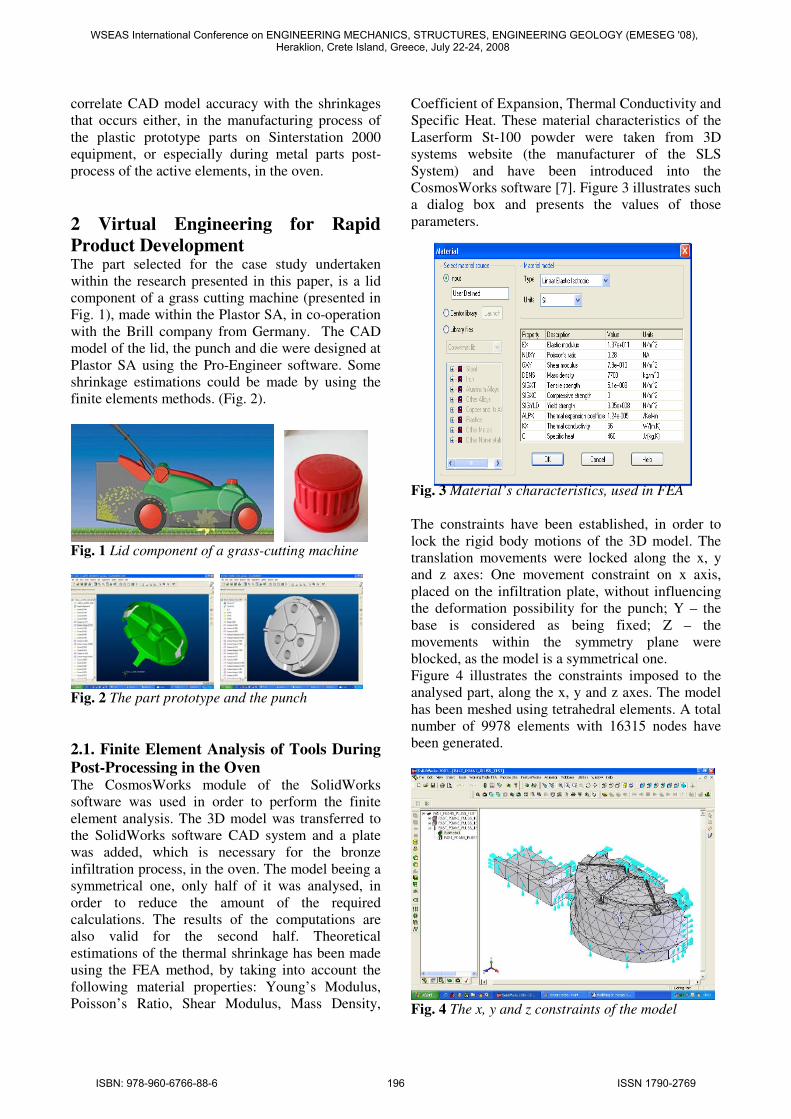
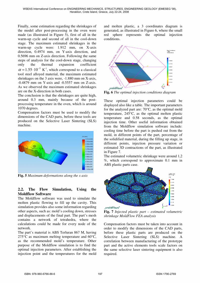
Product Development The part selected for the case study undertaken
within the research presented in this paper, is a lid
component of a grass cutting machine (presented in
Fig. 1), made within the Plastor SA, in co-operation
with the Brill company from Germany. The CAD
model of the lid, the punch and die were designed at
Plastor SA using the Pro-Engineer software. Some
shrinkage estimations could be made by using the
finite elements methods. (Fig. 2).
Fig. 1 Lid component of a grass-cutting machine
Fig. 2 The part prototype and the punch
2.1. Finite Element Analysis of Tools During
Post-Processing in the Oven The CosmosWorks module of the SolidWorks
software was used in order to perform the finite
element analysis. The 3D model was transferred to
the SolidWorks software CAD system and a plate
was added, which is necessary for the bronze
infiltration process, in the oven. The model beeing a
symmetrical one, only half of it was analysed, in
order to reduce the amount of the required
calculations. The results of the computations are
also valid for the second half. Theoretical
estimations of the thermal shrinkage has been made
using the FEA method, by taking into account the
following material properties: Young’s Modulus,
Poisson’s Ratio, Shear Modulus, Mass Density,
Coefficient of Expansion, Thermal Conductivity and
Specific Heat. These material characteristics of the
Laserform St-100 powder were taken from 3D
systems website (the manufacturer of the SLS
System) and have been introduced into the
CosmosWorks software [7]. Figure 3 illustrates such
a dialog box and presents the values of those
parameters.
Fig. 3 Material’s characteristics, used in FEA
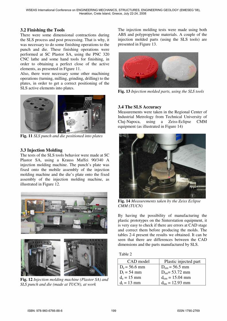
The constraints have been established, in order to
lock the rigid body motions of the 3D model. The
translation movements were locked along the x, y
and z axes: One movement constraint on x axis,
placed on the infiltration plate, without influencing
the deformation possibility for the punch; Y – the
base is considered as being fixed; Z – the
movements within the symmetry plane were
blocked, as the model is a symmetrical one.
Figure 4 illustrates the constraints imposed to the
analysed part, along the x, y and z axes. The model
has been meshed using tetrahedral elements. A total
number of 9978 elements with 16315 nodes have
been generated.
Fig. 4 The x, y and z constraints of the model
WSEAS International Conference on ENGINEERING MECHANICS, STRUCTURES, ENGINEERING GEOLOGY (EMESEG '08), Heraklion, Crete Island, Greece, July 22-24, 2008
ISBN: 978-960-6766-88-6 196 ISSN 1790-2769
Finally, some estimation regarding the shrinkages of
the model after post-processing in the oven were
made (as illustrated in Figure 5), first of all in the
warm-up cycle and second of all in the cool-down
stage. The maximum estimated shrinkages in the
warm-up cycle were: 1.912 mm, on X-axis
direction, 0.4974 mm, on Y-axis direction, and
0.5696 mm on Z-axis direction. Following the same
steps of analysis for the cool-down stage, changing
only the thermal expansion coefficient 51055.1 −
⋅=α K-1
, which correspond to a classical
tool steel alloyed material, the maximum estimated
shrinkages on the 3 axis were, -1.880 mm on X-axis,
-0.4879 mm on Y-axis and -0.5557 mm on Z-axis.
As we observed the maximum estimated shrinkages
are on the X-direction in both cases.
The conclusion is that the shrinkages are quite high,
around 0.3 mm, mainly because of the post-
processing temperature in the oven, which is around
1070 degrees.
Compensation factors must be used to modify the
dimensions of the CAD parts, before these tools are
produced on the Selective Laser Sintering (SLS)
machine.
Fig. 5 Maximum deformations along the x axis
2.2. The Flow Simulation, Using the
Moldflow Software The Moldflow software was used to simulate the
molten plastic flowing to fill up the cavity. This
simulation provides also some information regarding
other aspects, such as: mold’s cooling down, stresses
and displacements of the final part. The part’s mesh
contains a network of tetrahedra, where the
calculations could be made for every node of the
network.
The part’s material is ABS Terluran 867 M, having
275°C as maximum melting temperature and 60°C,
as the recommended mold’s temperature. Other
purpose of the Moldflow simulation is to find the
optimal injection parameters. After establishing the
injection point and the temperatures for the mold
and molten plastic, a 3 coordinates diagram is
generated, as illustrated in Figure 6, where the small
red sphere represents the optimal injection
conditions.
Fig. 6 The optimal injection conditions diagram
These optimal injection parameters could be
displayed also like a table. The important parameters
for the analyzed part are: 70°C, as the optimal mold
temperature, 245°C, as the optimal molten plastic
temperature and 0.58 seconds, as the optimal
injection time. Other useful information obtained
from the Moldflow simulation software include:
cooling time before the part is pushed out from the
mold, in different points of the part, percentage of
the solidified material, during the filling up stage, in
different points, injection pressure variation or
estimated 3D contractions of the part, as illustrated
in Figure 7.
The estimated volumetric shrinkage were around 1,2
%, which correspond to approximate 0.1 mm in
ABS plastic parts case.
Fig. 7 Injected plastic part – estimated volumetric
shrinkage MoldFlow FEA analysis
Compensation factors must be taken into account in
order to modify the dimensions of the CAD parts,
before these plastic parts are produced on the
Selective Laser Sintering (SLS) machine. A
correlation between manufacturing of the prototype
part and the active elements tools scale factors on
the same selective laser sintering equipment is also
required.
WSEAS International Conference on ENGINEERING MECHANICS, STRUCTURES, ENGINEERING GEOLOGY (EMESEG '08), Heraklion, Crete Island, Greece, July 22-24, 2008
ISBN: 978-960-6766-88-6 197 ISSN 1790-2769
3 Experimental Research As we can observe from the schematic diagram
presented in Figure 8, when speaking about
manufacturing the prototype and the active elements
(punch and die) on the same equipment,
Sinterstation 2000, it is very important to have a
good correlation between manufacturing processes,
in order to have a good result in the final level, when
the plastic parts are manufactured by injection
molding [8].
Fig. 8 The correlation between manufacturing
processes (schematic diagram)
3.1 Part Prototype and Tool Manufacturing
by Selective Laser Sintering (SLS) The virtual models of the parts were transferred to
the rapid prototyping machine, via the *.STL files. It
was possible to manufacture on the same machine,
both the part prototype from plastic (Duraform
polyamide) and the active elements punch and die
from a dedicated metallic powder (Laserform St-
100). All these experiments were carried out at the
Technical University of Cluj-Napoca (TUCN),
within the National Center of Rapid Prototyping,
using the Sinterstation 2000 equipment (Figure 9).
Fig. 9 Sinterstation 2000 machine – Technical
University of Cluj-Napoca
The compensation factors were used within the
manufacturing process, in order to get the same
values, both at the prototype part made on the SLS
machine and at the injected part made by injection
molding, using the active tools made on the SLS
machine as well.
The most important technological parameters used
for manufacturing the part prototype and the tools
on the SLS equipment are presented in Table 1.
Table 1
It is important to mention the fact that if for rapid
prototype made by Duraform Polyamide on the SLS
machine a post-processing stage is not necessary,
while speaking about tools manufacturing, in this
case, after manufacturing on the machine, a post-
process stage is needed in the oven. (Figure 10)
While post processing in the oven, the tools went
through the following steps:
- Melting (burning out) the polymer (at 450°C -
650°C), which was surrounding the metal grains
- Get fully sintered metal parts, while increasing the
temperature to about 700°C
- Infiltrating with bronze, at about 1050°C - 1070°C
- Cooling down the parts (natural / slow cooling).
The applied scale factors for the tools are taking into
account the shrinkages that occur mainly during the
post-processing stage, in the oven.
Fig. 10 SLS post processing in the oven, TUCN
Parameter Plastic
prototype part
(Duraform
Polyamide)
Punch and
die
(Laserform
St-100)
Scale factors X=1.03180,
Y=1.03309,
Z=1.01800
X=1.02054,
Y=1.02144,
Z=1.00950
Fill laser
power
5 W 28W
Slicer fill scan
spacing
0.15 mm 0.08 mm
Powder layer
thickness
0.1 mm 0.08 mm
Manufacturing
temperature
183˚C 98˚C
WSEAS International Conference on ENGINEERING MECHANICS, STRUCTURES, ENGINEERING GEOLOGY (EMESEG '08), Heraklion, Crete Island, Greece, July 22-24, 2008
ISBN: 978-960-6766-88-6 198 ISSN 1790-2769
3.2 Finishing the Tools There were some dimensional contractions during
the SLS process and post processing. That is why, it
was necessary to do some finishing operations to the
punch and die. These finishing operations were
performed at SC Plastor SA, using the PNC 320
CNC lathe and some hand tools for finishing, in
order to obtaining a perfect close of the active
elements, as presented in Figure 11.
Also, there were necessary some other machining
operations (turning, milling, grinding, drilling) to the
plates, in order to get a correct positioning of the
SLS active elements into plates.
Fig. 11 SLS punch and die positioned into plates
3.3 Injection Molding The tests of the SLS tools behavior were made at SC
Plastor SA, using a Krauss Maffei 90/340 A
injection molding machine. The punch’s plate was
fixed onto the mobile assembly of the injection
molding machine and the die’s plate onto the fixed
assembly of the injection molding machine, as
illustrated in Figure 12.
Fig. 12 Injection molding machine (Plastor SA) and
SLS punch and die (made at TUCN), at work
The injection molding tests were made using both
ABS and polypropylene materials. A couple of the
injection molded parts (using the SLS tools) are
presented in Figure 13.
Fig. 13 Injection molded parts, using the SLS tools
3.4 The SLS Accuracy
Measurements were taken in the Regional Center of
Industrial Metrology from Technical University of
Cluj-Napoca, using a Zeiss-Eclipse CMM
equipment (as illustrated in Figure 14)
Fig. 14 Measurements taken by the Zeiss Eclipse
CMM (TUCN)
By having the possibility of manufacturing the
plastic prototypes on the Sinterstation equipment, it
is very easy to check if there are errors at CAD stage
and correct them before producing the molds. The
tables 2-4 present the results we obtained. It can be
seen that there are differences between the CAD
dimensions and the parts manufactured by SLS.
Table 2
CAD model Plastic injected part
De = 56.6 mm
Di = 54 mm
de = 15 mm
di = 13 mm
Dem = 56.5 mm
Dim= 53.72 mm
dem = 15.04 mm
dim = 12.93 mm
WSEAS International Conference on ENGINEERING MECHANICS, STRUCTURES, ENGINEERING GEOLOGY (EMESEG '08), Heraklion, Crete Island, Greece, July 22-24, 2008
ISBN: 978-960-6766-88-6 199 ISSN 1790-2769
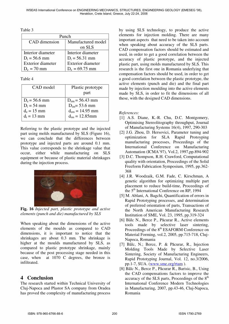
Table 3
Table 4
Referring to the plastic prototype and the injected
part using molds manufactured by SLS (Figure 16),
we can conclude that the differences between
prototype and injected parts are around 0.1 mm.
This value corresponds to the shrinkage value that
occur, either while manufacturing on SLS
equipment or because of plastic material shrinkages
during the injection process.
Fig. 16 Injected part, plastic prototype and active
elements (punch and die) manufactured by SLS
When speaking about the dimensions of the active
elements of the moulds as compared to CAD
dimensions, it is important to notice that the
shrinkages are about 0.3 mm. The shrinkage is
higher at the moulds manufactured by SLS, as
compared to plastic prototype shrinkage, mainly
because of the post processing stage needed in this
case, when at 1070 C degrees, the bronze is
infiltrated.
4 Conclusion The research started within Technical University of
Cluj-Napoca and Plastor SA company from Oradea
has proved the complexity of manufacturing process
by using SLS technology, to produce the active
elements for injection molding. There are many
important aspects that need to be taken into account
when speaking about accuracy of the SLS parts.
CAD compensation factors should be estimated and
used, in order to get a good correlation between the
accuracy of plastic prototype, and the injected
plastic part, using molds manufactured by SLS. This
research is the first one in Romania underlying that
compensation factors should be used, in order to get
a good correlation between the plastic prototype, the
active elements (punch and die) and the final part
made by injection moulding into the active elements
made by SLS, in order to fit the dimensions of all
these, with the designed CAD dimensions.
References:
[1] A.S. Diane, K.-R. Chu, D.C. Montgomery,
Optimising Stereolitography throughput, Journal
of Manufacturing Systems 16(4), 1997, 290-303
[2] J.G. Zhou, D. Hersovici, Parameter tuning and
optimization for SLA Rapid Protoyping
manufacturing processes, Proceedings of the
International Conference on Manufacturing
Automation (ICMA’97), Vol.2, 1997,pp.894-902
[3] D.C. Thompson, R.H. Crawford, Computational
quality with orientation, Proceedings of the Solid
Freeform Fabrication Symposium, 1995, pp.362-
368
[4] J.R. Woodzaik, G.M. Fade, C. Kirschman, A
genetic algorithm for optimizing multiple part
placement to reduce build-time, Proceedings of
the 5th International Conference on RP, 1994
[5] M. Ablani, A. Bagchi, Quantification of errors in
Rapid Prototyping processes, and determination
of preferred orientation of parts, Transactions of
the North American Manufacturing Research
Institution of SME, Vol. 23, 1995, pp.319-324
[6] Bâlc N., Berce P., Păcurar R., Active elements
tools made by selective laser sintering,
Proceedings of the 8th ESAFORM Conference on
Material Forming, vol.2, 2005, pp.715-718, Cluj-
Napoca, Romania
[7] Bâlc, N.; Berce, P. & Păcurar, R., Injection
Molding Tools Made by Selective Laser
Sintering, Society of Manufacturing Engineers,
Rapid Prototyping Journal, Vol. 12, no.3/2006,
pp.1-7, SUA. (www.sme.org/rtam ).
[8] Bâlc N., Berce P., Păcurar R., Barisic, B., Using
the CAD compensations factors to improve the
accuracy of the SLS parts, Proceedings of the 8th
International Conference Modern Technologies
in Manufacturing, 2007, pp.43-46, Cluj-Napoca,
Romania
Punch
CAD dimension Manufactured model
on SLS
Interior diameter
Di = 56.6 mm
Exterior diameter
De = 70 mm
Interior diameter
Di = 56.31 mm
Exterior diameter
De = 69.75 mm
CAD model Plastic prototype
part
De = 56.6 mm
Di = 54 mm
de = 15 mm
di = 13 mm
Dem = 56.43 mm
Dim= 53.6 mm
dem = 14.95 mm
dim = 12.85mm
WSEAS International Conference on ENGINEERING MECHANICS, STRUCTURES, ENGINEERING GEOLOGY (EMESEG '08), Heraklion, Crete Island, Greece, July 22-24, 2008
ISBN: 978-960-6766-88-6 200 ISSN 1790-2769