Embed Size (px)
Citation preview
Page 1
Virtual Connect CLI Network Management Guide with Nexus vPC Configuration
Feedback: [email protected]
Page 2
Revision History
Revision Number Date Changes
1.1 1/11/2012 First Edition
Page 3
• Introduction
• Network Hardware Topology and Virtual Connect Port Numbering
• Virtual Connect Terminology and CLI Summary Table
• Virtual Connect CLI Snapshots
• Troubleshooting Scenario 1: Track Down MAC Address
• Troubleshooting Scenario 2: Display VLAN MAC table
• Appendix #1: vPC Configuration: Nexus5000-1
• Appendix #2: vPC Configuration: Nexus5000-2
• Appendix #3: Configuration: Virtual Connect
• Reference Links
Table of Contents

Page 4
Introduction
Page 5
Introduction
• This guide is targeted to network administrators who want to manage Virtual Connect network part of configuration by CLI. It also demos how to configure Nexus vPC with Virtual Connect.
• Most of Virtual Connect management tasks can be categorized into two parts: Network and Server Profile. Some customers network team will handle VC network configuration while server team will handle VC Server Profile configuration. Others may choose to have server admins to own the configuration for the whole Virtual Connect module.
• Virtual Connect can be managed by GUI or CLI mode. Each mode offers full configuration functionality.
• Many network admins like to manage VC by CLI and this guide is to help them on this task. Network configuration can be done by GUI mode as well. Please refer to VC GUI user guide and other links at the end of this presentation for more GUI configuration information.
• This guide does not cover server profile part of CLI management as many server admins prefer VC GUI for server configuration. Please refer to VC CLI user guide link at the end of this presentation on CLI syntax to manage server profile.

Page 6
Network Hardware Topology and Virtual Connect Port Numbering
Page 7
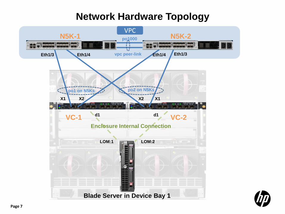
Network Hardware Topology
Eth1/3 Eth1/4 Eth1/3 Eth1/4
X1 X2 X2 X1
d1 d1
Blade Server in Device Bay 1
LOM:1 LOM:2
N5K-1 N5K-2 po1000
vpc peer-link
VC-1 VC-2
po1 on N5Ks po2 on N5Ks
VPC
Enclosure Internal Connection

Page 8
Virtual Connect FlexFabric Module Port Numbering
d1 d2 d3 d4 d5 d6 d7 d8 d9 d10 d11 d12 d13 d14 d15 d16
X1 X2 X3 X4 X5 X7 X6 X8
Bay 1
Bay 2
Bay 3
Bay 4
Bay 5
Bay 6
Bay 7
Bay 8
Bay 9
Bay 10
Bay 11
Bay 12
Bay 13
Bay 14
Bay 15
Bay 16
Enclosure Internal Connection
Note: • X1-X4: Besides 10G ethernet, these 4 ports can be configured as native Fibre Channel(Note: it’s FC, not
FCOE) on port-by-port basis to connect with SAN switches. Default port mode is ethernet. • X5-X8: Support 1G or 10G ethernet on port-by-port basis
Page 9
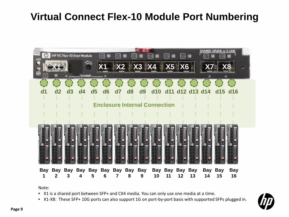
Virtual Connect Flex-10 Module Port Numbering
X1 X2 X3 X4 X5 X7 X6 X8
d1 d2 d3 d4 d5 d6 d7 d8 d9 d10 d11 d12 d13 d14 d15 d16
Bay 1
Bay 2
Bay 3
Bay 4
Bay 5
Bay 6
Bay 7
Bay 8
Bay 9
Bay 10
Bay 11
Bay 12
Bay 13
Bay 14
Bay 15
Bay 16
Enclosure Internal Connection
X1
Note: • X1 is a shared port between SFP+ and CX4 media. You can only use one media at a time. • X1-X8: These SFP+ 10G ports can also support 1G on port-by-port basis with supported SFPs plugged in.
Page 10
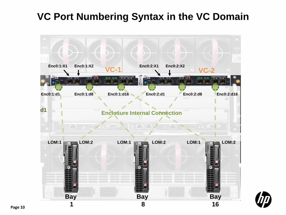
VC Port Numbering Syntax in the VC Domain
Enc0:1:X1
Enc0:1:d1 Enc0:2:d1
Bay 1
LOM:1 LOM:2
VC-1 VC-2
d1
Bay 8
Bay 16
Enc0:1:d8 Enc0:1:d16 Enc0:2:d8 Enc0:2:d16
Enc0:1:X2 Enc0:2:X1 Enc0:2:X2
LOM:1 LOM:2 LOM:1 LOM:2
Enclosure Internal Connection

Page 11
Virtual Connect Terminology and CLI Summary Table
Page 12
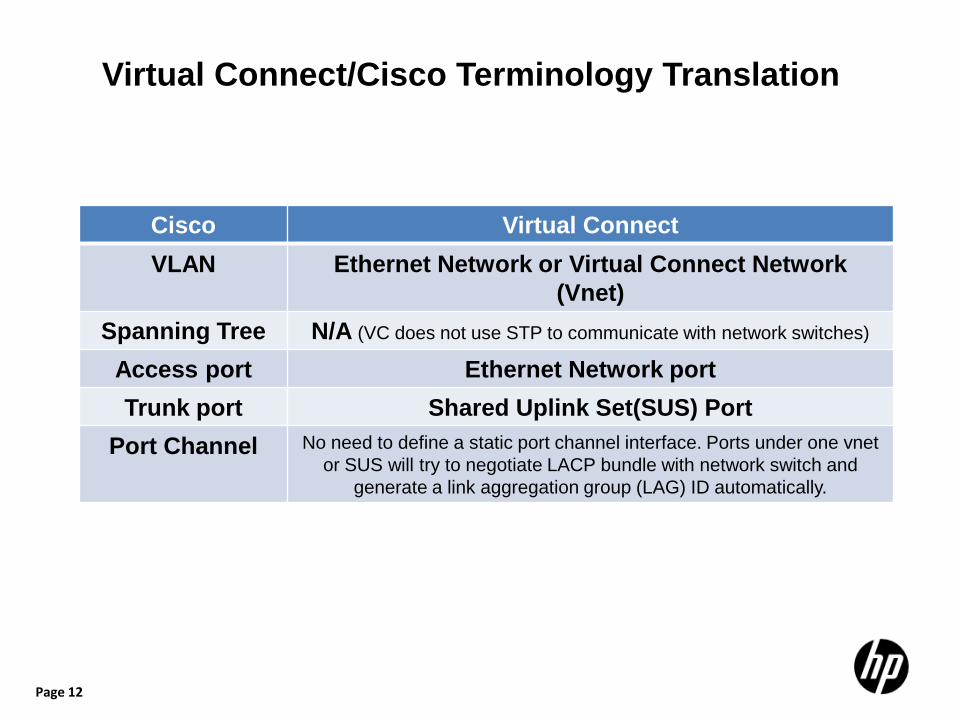
Virtual Connect/Cisco Terminology Translation
Cisco Virtual Connect VLAN Ethernet Network or Virtual Connect Network
(Vnet) Spanning Tree N/A (VC does not use STP to communicate with network switches)
Access port Ethernet Network port Trunk port Shared Uplink Set(SUS) Port
Port Channel No need to define a static port channel interface. Ports under one vnet or SUS will try to negotiate LACP bundle with network switch and
generate a link aggregation group (LAG) ID automatically.

Page 13
Virtual Connect/Cisco CLI Comparison Cisco Virtual Connect
System Information
Show version Show version
Show module Show interconnect Show device-bay
Show cdp neighbor N/A (VC doesn’t support CDP)
Show lldp neighbor Show lldp
Show interface brief Show uplinkport Show server-port
Show spanning-tree N/A (VC doesn’t use STP to communicate with network switches)
Show vlan Show network
• If ports are trunk ports Show int switchport Show int trunk
• If ports are access ports Show int switchport
• If ports are in LACP bundle Show port-channel summary Show port-channel database
• If ports are trunk ports Show uplinkset <uplinkset name>
• If ports are access ports Show network <ethernet network name>
• If ports are in LACP bundle Show network <ethernet network name> Show uplinkset Show uplinkset <uplinkset name> Show uplinkport <port number>
Configuration
• Configuring access port Vlan <number> Switchport mode access Switchport access vlan <number>
• Configuring trunk port Vlan <number> Switchport mode trunk Switchport trunk allowed vlan <number>
• Configuring port-channel Channel group <number> mode Int port-channel <number>
• Configuring upstream access port Add network <name> Add uplinkport <port> network=<name>
• Configuring upstream trunk port Add uplinkset <name> Add uplinkport <number> uplinkset=<name> Add network-range
• Configuring upstream port-channel No need to configure manually. Automatically negotiated
• Note: Downlink server ports mode are configured in Server Profile
Page 14
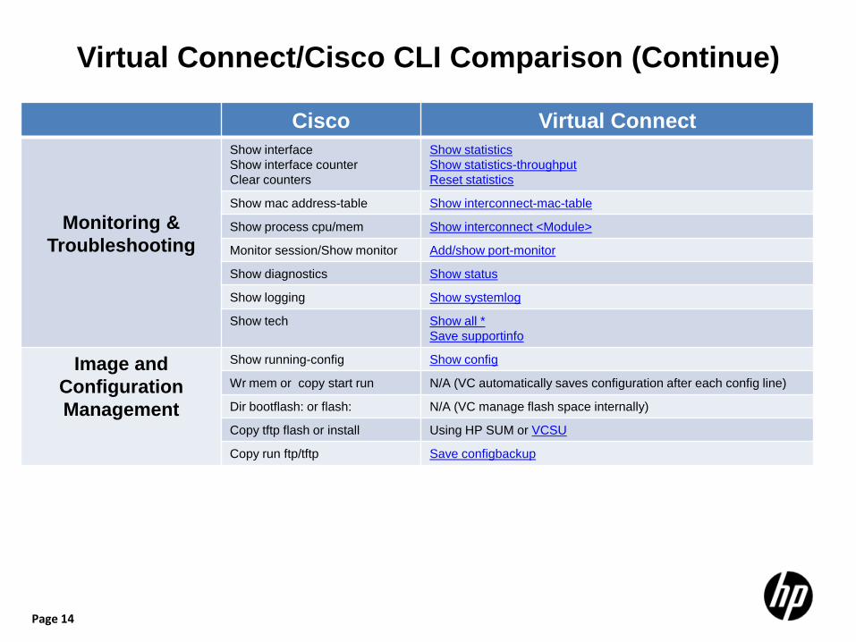
Virtual Connect/Cisco CLI Comparison (Continue)
Cisco Virtual Connect
Monitoring & Troubleshooting
Show interface Show interface counter Clear counters
Show statistics Show statistics-throughput Reset statistics
Show mac address-table Show interconnect-mac-table
Show process cpu/mem Show interconnect <Module>
Monitor session/Show monitor Add/show port-monitor
Show diagnostics Show status
Show logging Show systemlog
Show tech Show all * Save supportinfo
Image and Configuration Management
Show running-config Show config
Wr mem or copy start run N/A (VC automatically saves configuration after each config line)
Dir bootflash: or flash: N/A (VC manage flash space internally)
Copy tftp flash or install Using HP SUM or VCSU
Copy run ftp/tftp Save configbackup
Page 15
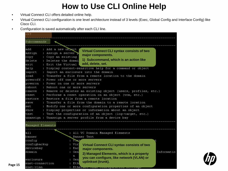
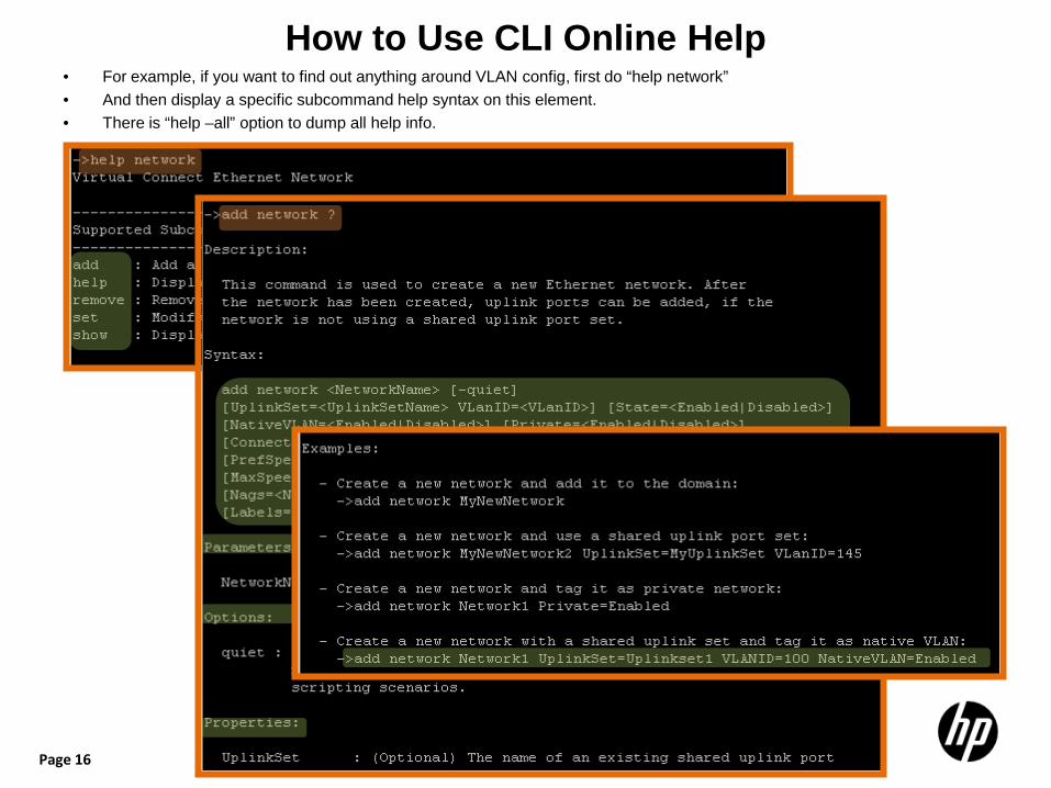
How to Use CLI Online Help • Virtual Connect CLI offers detailed online help. • Virtual Connect CLI configuration is one level architecture instead of 3 levels (Exec, Global Config and Interface Config) like
Cisco CLI. • Configuration is saved automatically after each CLI line.
15
Virtual Connect CLI syntax consists of two major components. 1) Subcommand, which is an action like add, delete, set.
Virtual Connect CLI syntax consists of two major components. 2) Managed Elements, which is a property you can configure, like network (VLAN) or uplinkset (trunk).
Page 16
How to Use CLI Online Help • For example, if you want to find out anything around VLAN config, first do “help network” • And then display a specific subcommand help syntax on this element. • There is “help –all” option to dump all help info.
16
Page 17
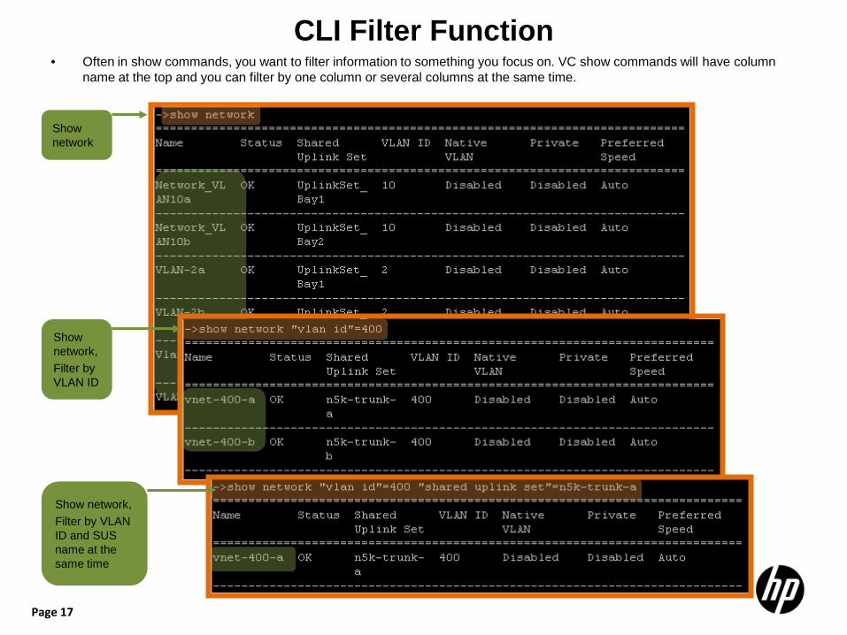
CLI Filter Function • Often in show commands, you want to filter information to something you focus on. VC show commands will have column
name at the top and you can filter by one column or several columns at the same time.
Show network
Show network, Filter by VLAN ID
Show network, Filter by VLAN ID and SUS name at the same time
Page 18
Virtual Connect CLI Snapshots

Page 19
Show Version (Cisco: show version)
VC 3.30 release
Page 20
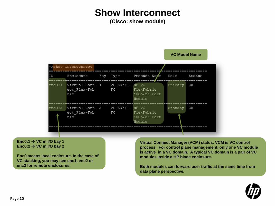
Show Interconnect (Cisco: show module)
VC Model Name
Virtual Connect Manager (VCM) status. VCM is VC control process. For control plane management, only one VC module is active in a VC domain. A typical VC domain is a pair of VC modules inside a HP blade enclosure. Both modules can forward user traffic at the same time from data plane perspective.
Enc0:1 VC in I/O bay 1 Enc0:2 VC in I/O bay 2 Enc0 means local enclosure. In the case of VC stacking, you may see enc1, enc2 or enc3 for remote enclosures.
Page 21
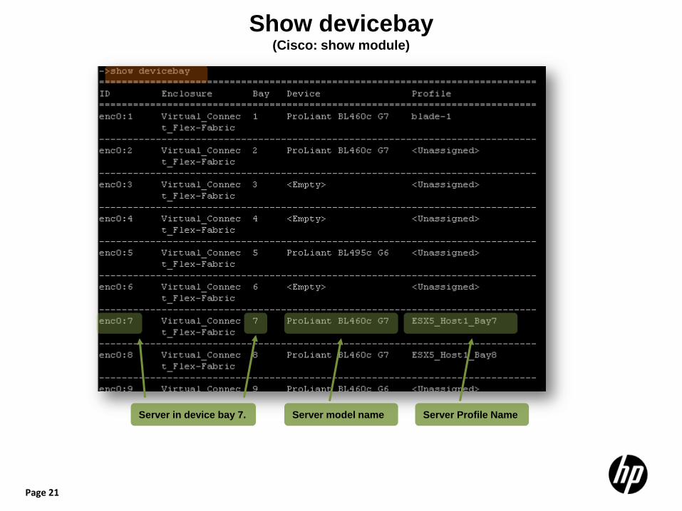
Show devicebay (Cisco: show module)
Server in device bay 7. Server model name Server Profile Name
Page 22
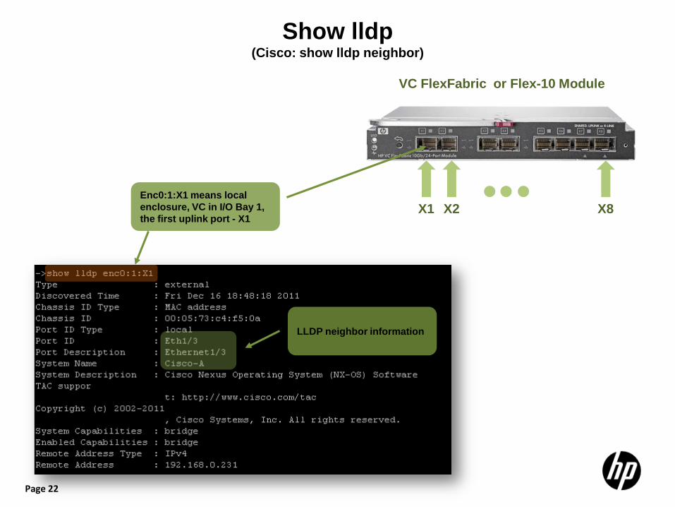
Show lldp (Cisco: show lldp neighbor)
X1 X2 X8
VC FlexFabric or Flex-10 Module
Enc0:1:X1 means local enclosure, VC in I/O Bay 1, the first uplink port - X1
LLDP neighbor information
Page 23
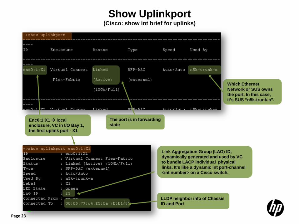
Show Uplinkport (Cisco: show int brief for uplinks)
Enc0:1:X1 local enclosure, VC in I/O Bay 1, the first uplink port - X1
The port is in forwarding state
Which Ethernet Network or SUS owns the port. In this case, it’s SUS “n5k-trunk-a”.
Link Aggregation Group (LAG) ID, dynamically generated and used by VC to bundle LACP individual physical links. It’s like a dynamic int port-channel <int number> on a Cisco switch.
LLDP neighbor info of Chassis ID and Port
Page 24
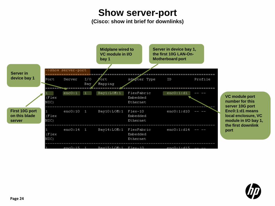
Show server-port (Cisco: show int brief for downlinks)
First 10G port on this blade server
Server in device bay 1
Server in device bay 1, the first 10G LAN-On-Motherboard port
Midplane wired to VC module in I/O bay 1
VC module port number for this server 10G port Enc0:1:d1 means local enclosure, VC module in I/O bay 1, the first downlink port
Page 25
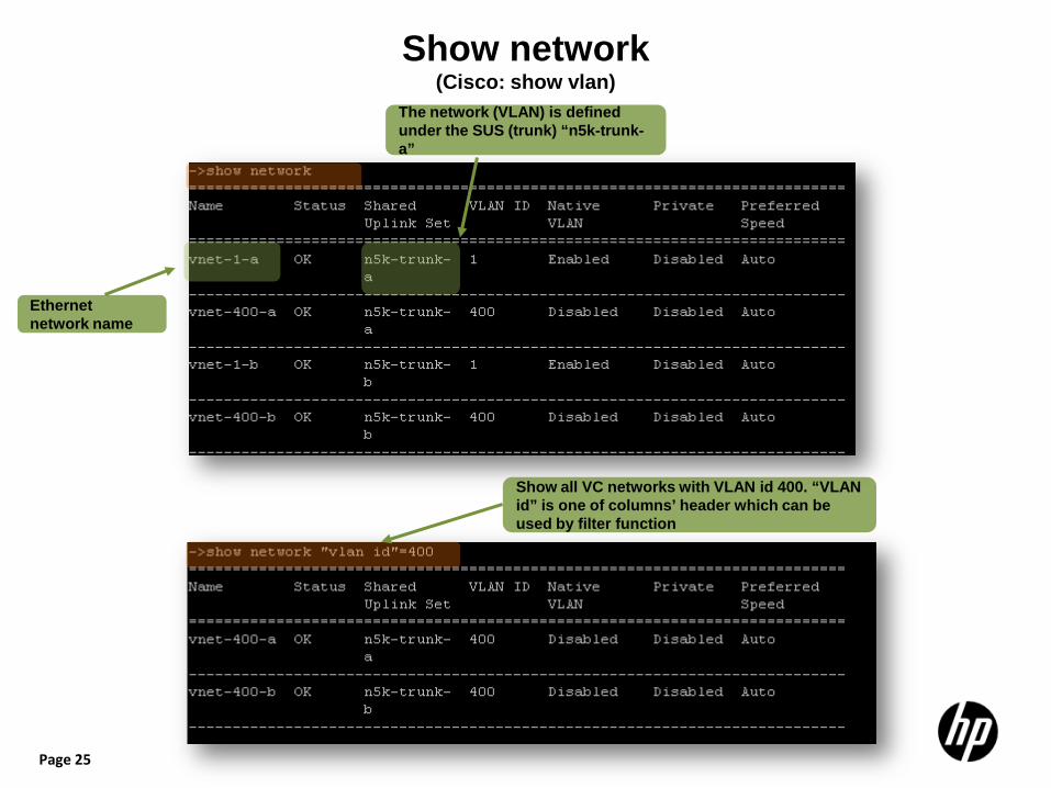
Show network (Cisco: show vlan)
Ethernet network name
The network (VLAN) is defined under the SUS (trunk) “n5k-trunk-a”
Show all VC networks with VLAN id 400. “VLAN id” is one of columns’ header which can be used by filter function
Page 26
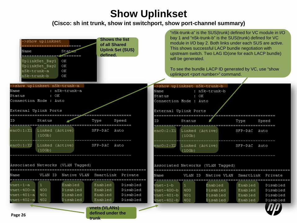
Show Uplinkset (Cisco: sh int trunk, show int switchport, show port-channel summary)
Shows the list of all Shared Uplink Set (SUS) defined.
“n5k-trunk-a” is the SUS(trunk) defined for VC module in I/O bay 1 and “n5k-trunk-b” is the SUS(trunk) defined for VC module in I/O bay 2. Both links under each SUS are active. This shows successful LACP bundle negotiation with upstream switch. Two LAG ID(one for each LACP bundle) will be generated. To see the bundle LACP ID generated by VC, use “show uplinkport <port number>” command.
vnets (VLANs) defined under the trunk
Page 27
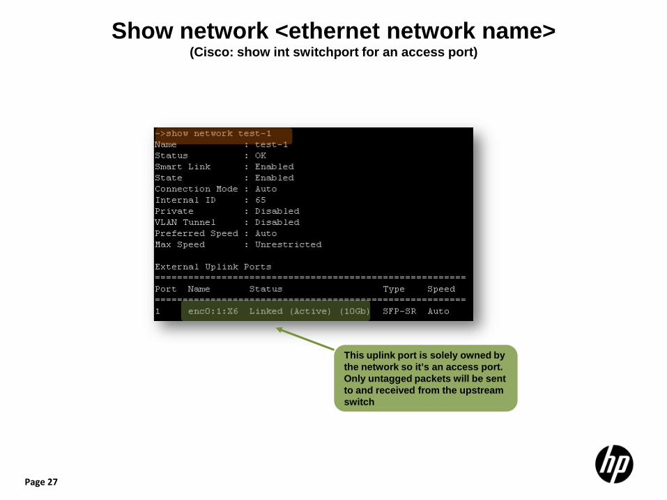
Show network <ethernet network name> (Cisco: show int switchport for an access port)
This uplink port is solely owned by the network so it’s an access port. Only untagged packets will be sent to and received from the upstream switch
Page 28
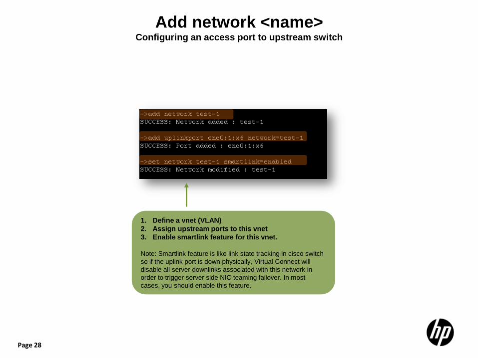
Add network <name> Configuring an access port to upstream switch
1. Define a vnet (VLAN) 2. Assign upstream ports to this vnet 3. Enable smartlink feature for this vnet.
Note: Smartlink feature is like link state tracking in cisco switch so if the uplink port is down physically, Virtual Connect will disable all server downlinks associated with this network in order to trigger server side NIC teaming failover. In most cases, you should enable this feature.
Page 29
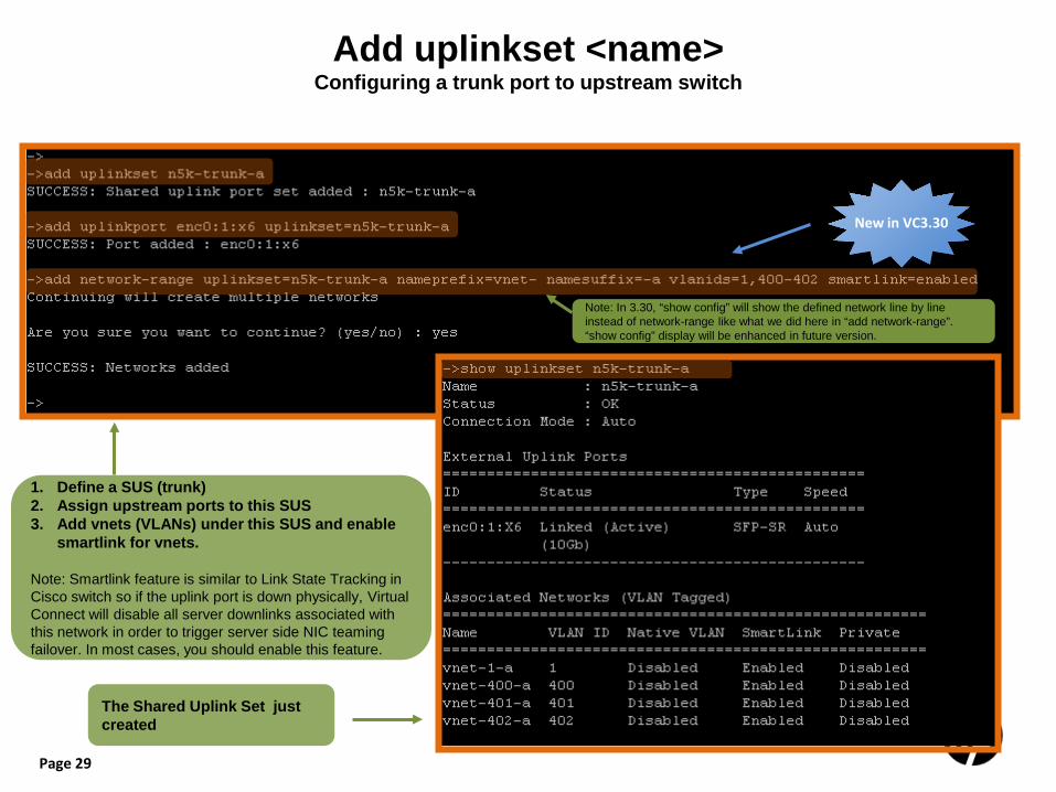
Add uplinkset <name> Configuring a trunk port to upstream switch
1. Define a SUS (trunk) 2. Assign upstream ports to this SUS 3. Add vnets (VLANs) under this SUS and enable
smartlink for vnets.
Note: Smartlink feature is similar to Link State Tracking in Cisco switch so if the uplink port is down physically, Virtual Connect will disable all server downlinks associated with this network in order to trigger server side NIC teaming failover. In most cases, you should enable this feature.
The Shared Uplink Set just created
New in VC3.30
Note: In 3.30, “show config” will show the defined network line by line instead of network-range like what we did here in “add network-range”. “show config” display will be enhanced in future version.
Page 30
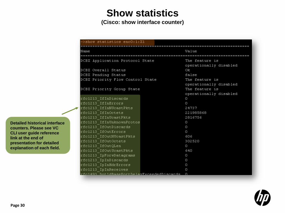
Show statistics (Cisco: show interface counter)
Detailed historical interface counters. Please see VC CLI user guide reference link at the end of presentation for detailed explanation of each field.
Page 31
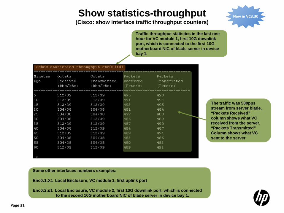
Show statistics-throughput (Cisco: show interface traffic throughput counters)
Some other interfaces numbers examples: Enc0:1:X1 Local Enclosure, VC module 1, first uplink port Enc0:2:d1 Local Enclosure, VC module 2, first 10G downlink port, which is connected
to the second 10G motherboard NIC of blade server in device bay 1.
Traffic throughput statistics in the last one hour for VC module 1, first 10G downlink port, which is connected to the first 10G motherboard NIC of blade server in device bay 1.
New in VC3.30
The traffic was 500pps stream from server blade. “Packets Received” column shows what VC received from the server, “Packets Transmitted” Column shows what VC sent to the server
Page 32
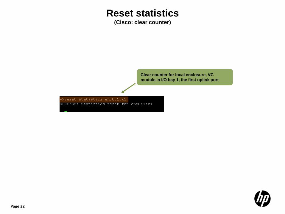
Reset statistics (Cisco: clear counter)
Clear counter for local enclosure, VC module in I/O bay 1, the first uplink port

Page 33
Show interconnect-mac-table (Cisco: show mac address-table)
New in VC3.30
Display VC-1 MAC table, enc0:1 means local enclosure VC module in I/O bay 1. Also filter by a mac address in “mac address” column
Display VC-2 MAC table
For detailed MAC address troubleshooting, please check section Troubleshooting Scenario 1: Track a MAC address inside Virtual Connect
Page 34
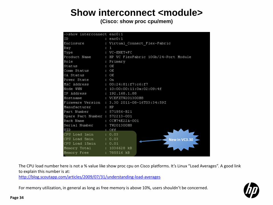
Show interconnect <module> (Cisco: show proc cpu/mem)
New in VC3.30
The CPU load number here is not a % value like show proc cpu on Cisco platforms. It’s Linux “Load Averages”. A good link to explain this number is at: http://blog.scoutapp.com/articles/2009/07/31/understanding-load-averages For memory utilization, in general as long as free memory is above 10%, users shouldn’t be concerned.
Page 35
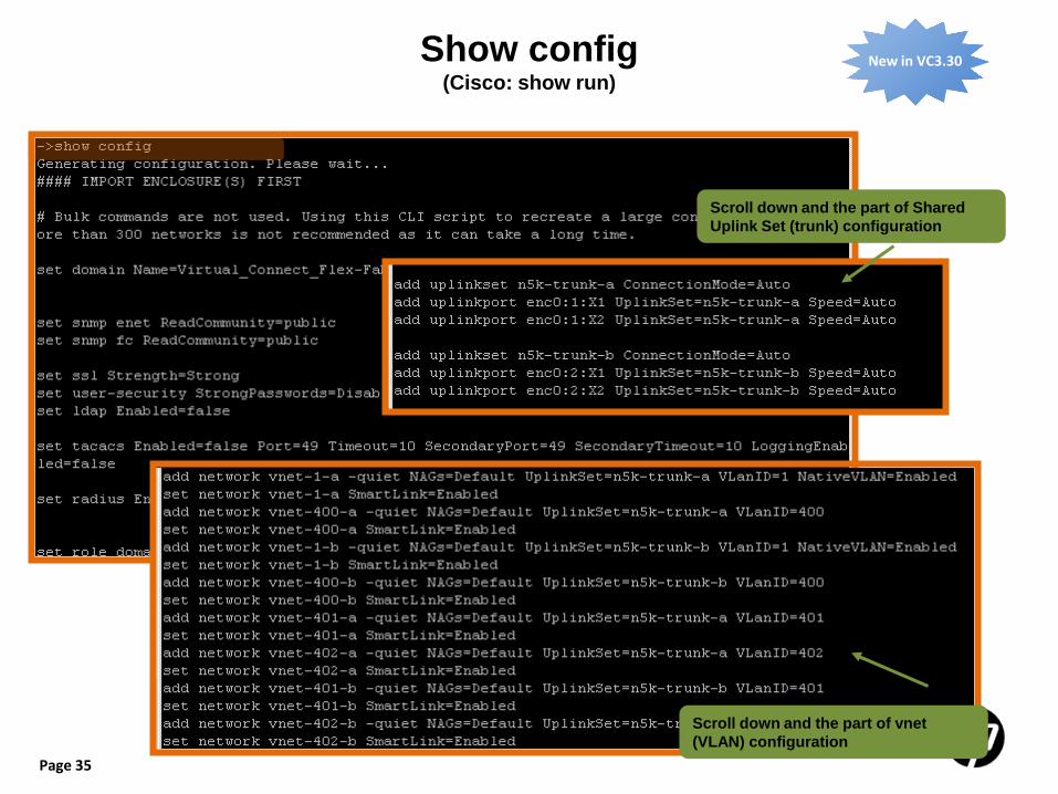
Show config (Cisco: show run)
New in VC3.30
Scroll down and the part of Shared Uplink Set (trunk) configuration
Scroll down and the part of vnet (VLAN) configuration
Page 36
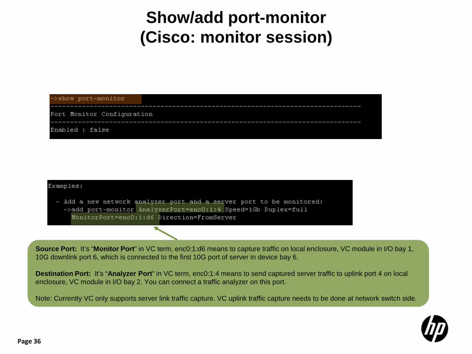
Show/add port-monitor (Cisco: monitor session)
Source Port: It’s “Monitor Port” in VC term, enc0:1:d6 means to capture traffic on local enclosure, VC module in I/O bay 1, 10G downlink port 6, which is connected to the first 10G port of server in device bay 6. Destination Port: It’s “Analyzer Port” in VC term, enc0:1:4 means to send captured server traffic to uplink port 4 on local enclosure, VC module in I/O bay 2. You can connect a traffic analyzer on this port. Note: Currently VC only supports server link traffic capture. VC uplink traffic capture needs to be done at network switch side.
Page 37
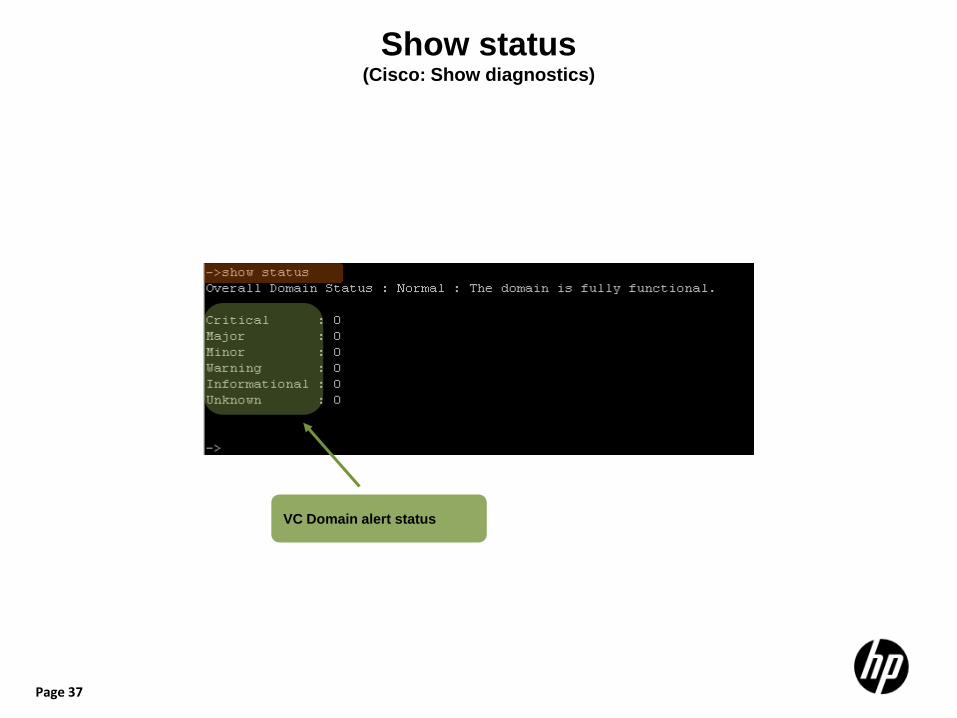
Show status (Cisco: Show diagnostics)
VC Domain alert status
Page 38
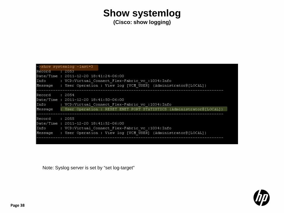
Show systemlog (Cisco: show logging)
Note: Syslog server is set by “set log-target”
Page 39
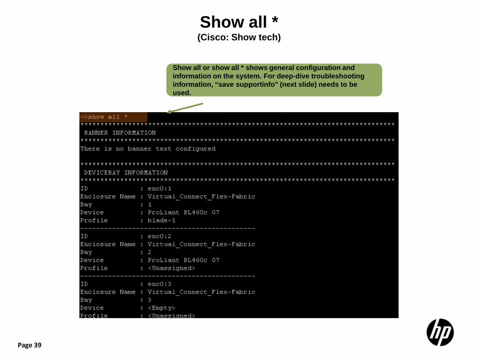
Show all * (Cisco: Show tech)
Show all or show all * shows general configuration and information on the system. For deep-dive troubleshooting information, “save supportinfo” (next slide) needs to be used.
Page 40
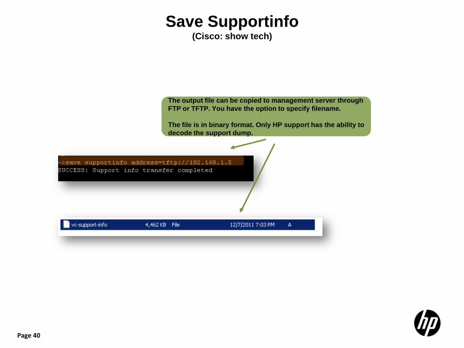
Save Supportinfo (Cisco: show tech)
The output file can be copied to management server through FTP or TFTP. You have the option to specify filename. The file is in binary format. Only HP support has the ability to decode the support dump.
Page 41
Virtual Connect Upgrade Using Virtual Connect Support Utility (VCSU)
41
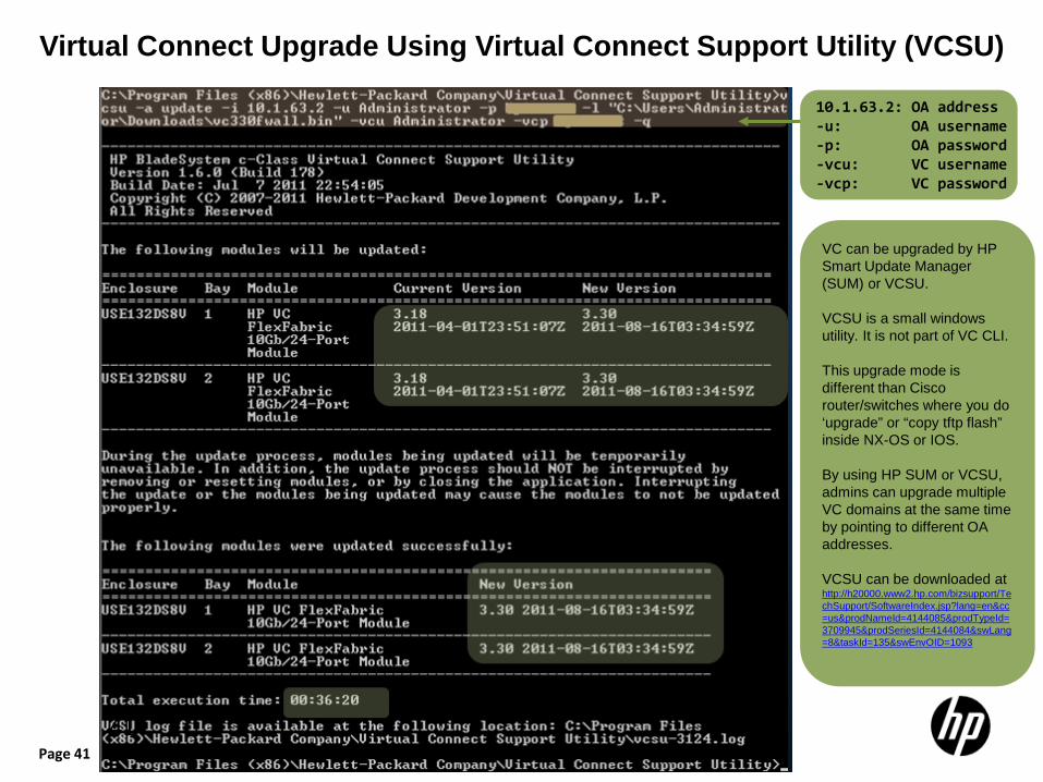
10.1.63.2: OA address -u: OA username -p: OA password -vcu: VC username -vcp: VC password
VC can be upgraded by HP Smart Update Manager (SUM) or VCSU. VCSU is a small windows utility. It is not part of VC CLI. This upgrade mode is different than Cisco router/switches where you do ‘upgrade” or “copy tftp flash” inside NX-OS or IOS. By using HP SUM or VCSU, admins can upgrade multiple VC domains at the same time by pointing to different OA addresses. VCSU can be downloaded at http://h20000.www2.hp.com/bizsupport/TechSupport/SoftwareIndex.jsp?lang=en&cc=us&prodNameId=4144085&prodTypeId=3709945&prodSeriesId=4144084&swLang=8&taskId=135&swEnvOID=1093

Page 42
Save configbackup
The exported config file is a binary file which you can load it back to the same enclosure to restore domain config. To see config in text format, please use “show config”. Please don’t load this binary file to other enclosures as a way to replicate configuration as the config binary file contains specific internal domain information.
Page 43
Troubleshooting Scenario 1:
Objective: Track down the path of MAC address 00:50:56:12:12:12 (a VM NIC address) and understand the logical topology related with it.
Page 44
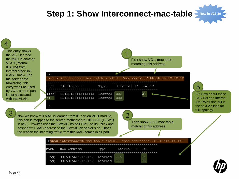
Step 1: Show Interconnect-mac-table New in VC3.30
Now we know this MAC is learned from d1 port on VC-1 module, this port is mapped to the server motherboard 10G NIC1 (LOM:1) in bay 1. Vswitch uses the FlexNIC inside LOM:1 as its uplink and hashed vm1 MAC address to the FlexNIC on server side. That’s the reason the incoming traffic from this MAC comes in d1 port
Then show VC-2 mac table matching this address
First show VC-1 mac table matching this address
But How about these LAG IDs and Internal IDs? We’ll find out in the next 2 slides for full topology
This entry shows the VC-1 learned the MAC in another VLAN (internal ID=235) from internal stack link (LAG ID=26). For the server data forwarding, this entry won’t be used by VC-1 as “d1” port is not associated with this VLAN.
1
2 3
4
5
Page 45
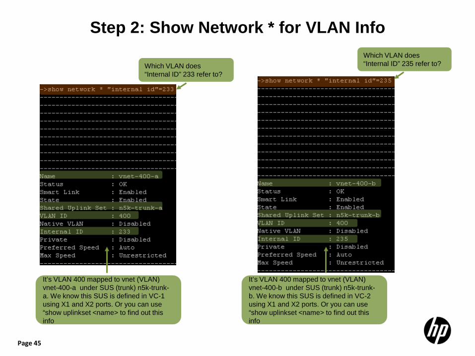
Step 2: Show Network * for VLAN Info
Which VLAN does “Internal ID” 233 refer to?
It’s VLAN 400 mapped to vnet (VLAN) vnet-400-a under SUS (trunk) n5k-trunk-a. We know this SUS is defined in VC-1 using X1 and X2 ports. Or you can use “show uplinkset <name> to find out this info
It’s VLAN 400 mapped to vnet (VLAN) vnet-400-b under SUS (trunk) n5k-trunk-b. We know this SUS is defined in VC-2 using X1 and X2 ports. Or you can use “show uplinkset <name> to find out this info
Which VLAN does “Internal ID” 235 refer to?
Page 46
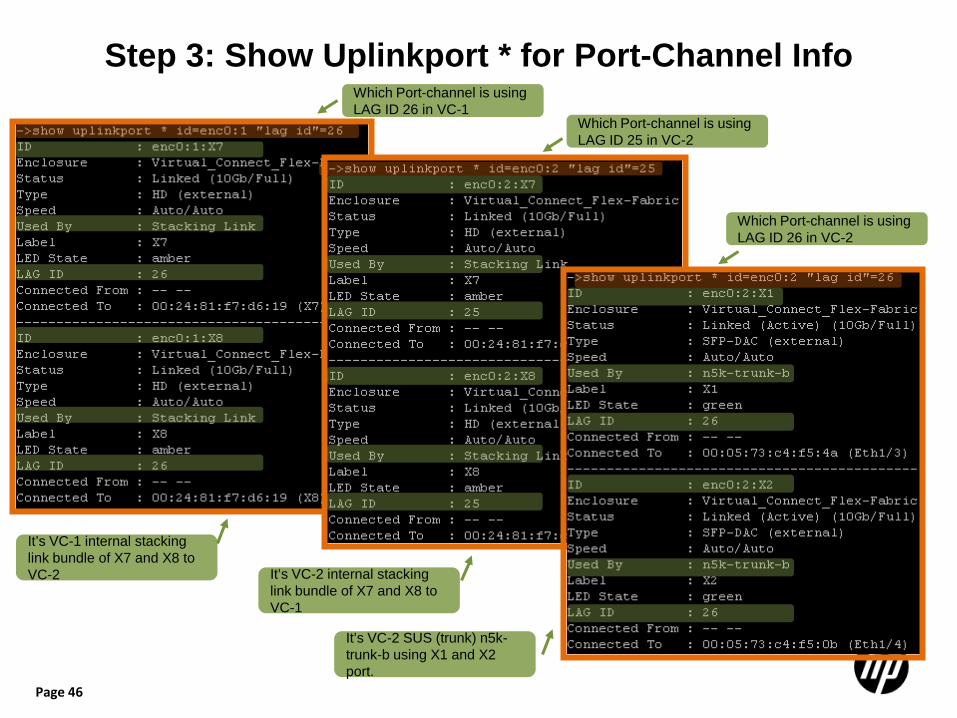
Step 3: Show Uplinkport * for Port-Channel Info
It’s VC-1 internal stacking link bundle of X7 and X8 to VC-2
Which Port-channel is using LAG ID 25 in VC-2
Which Port-channel is using LAG ID 26 in VC-2
It’s VC-2 internal stacking link bundle of X7 and X8 to VC-1
It’s VC-2 SUS (trunk) n5k-trunk-b using X1 and X2 port.
Which Port-channel is using LAG ID 26 in VC-1
Page 47
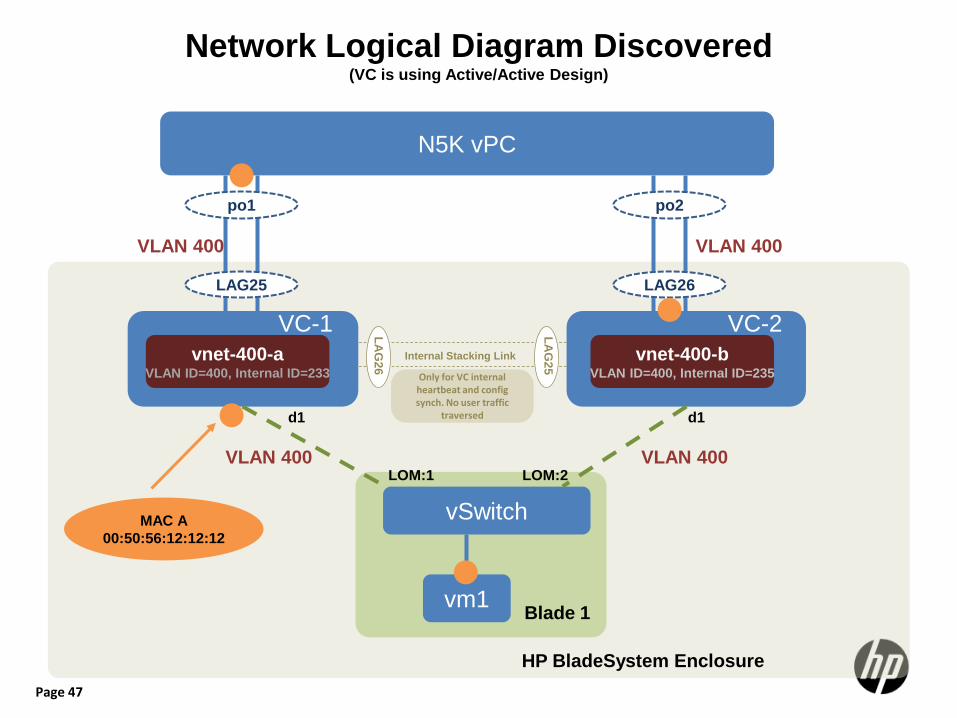
Only for VC internal heartbeat and config synch. No user traffic
traversed
Network Logical Diagram Discovered (VC is using Active/Active Design)
N5K vPC
vSwitch
vm1
LAG25
po1
LAG26
po2
d1
vnet-400-a VLAN ID=400, Internal ID=233
VLAN 400 VLAN 400
VLAN 400 VLAN 400
d1
VC-1 VC-2 vnet-400-b
VLAN ID=400, Internal ID=235
HP BladeSystem Enclosure
LAG
26
LAG
25
Blade 1
Internal Stacking Link
MAC A 00:50:56:12:12:12
LOM:1 LOM:2
Page 48
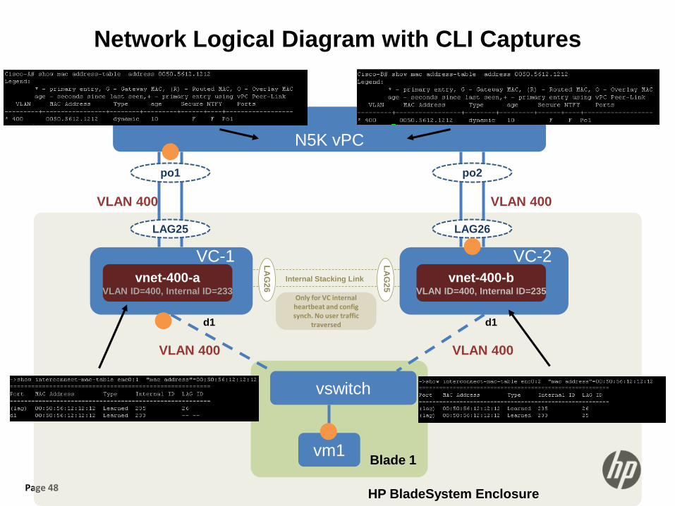
Network Logical Diagram with CLI Captures
N5K vPC
vswitch
vm1
LAG25
po1
LAG26
po2
d1
vnet-400-a VLAN ID=400, Internal ID=233
VLAN 400 VLAN 400
VLAN 400 VLAN 400
d1
VC-1 VC-2 vnet-400-b
VLAN ID=400, Internal ID=235
HP BladeSystem Enclosure
LAG
26
LAG
25
Blade 1
Internal Stacking Link
Only for VC internal heartbeat and config synch. No user traffic
traversed
Page 49
Troubleshooting Scenario 2:
Objective: Display VLAN 400 MAC address table in both VC modules
Page 50
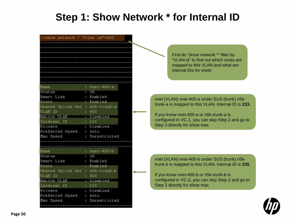
Step 1: Show Network * for Internal ID
First do “show network *” filter by “VLAN id” to find out which vnets are mapped to this VLAN and what are internal IDs for vnets
vnet (VLAN) vnet-400-a under SUS (trunk) n5k-trunk-a is mapped to this VLAN. Internal ID is 233. If you know vnet-400-a or n5k-trunk-a is configured in VC-1, you can skip Step 2 and go to Step 3 directly for show mac
vnet (VLAN) vnet-400-b under SUS (trunk) n5k-trunk-b is mapped to this VLAN. Internal ID is 235. If you know vnet-400-b or n5k-trunk-b is configured in VC-2, you can skip Step 2 and go to Step 3 directly for show mac
Page 51
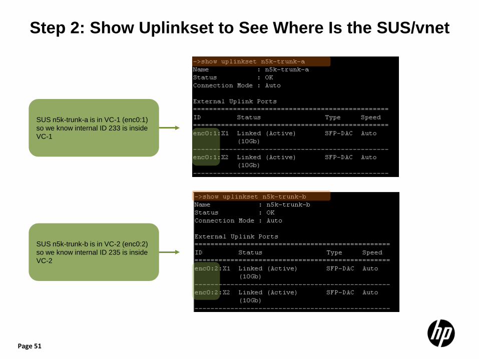
Step 2: Show Uplinkset to See Where Is the SUS/vnet
SUS n5k-trunk-a is in VC-1 (enc0:1) so we know internal ID 233 is inside VC-1
SUS n5k-trunk-b is in VC-2 (enc0:2) so we know internal ID 235 is inside VC-2
Page 52
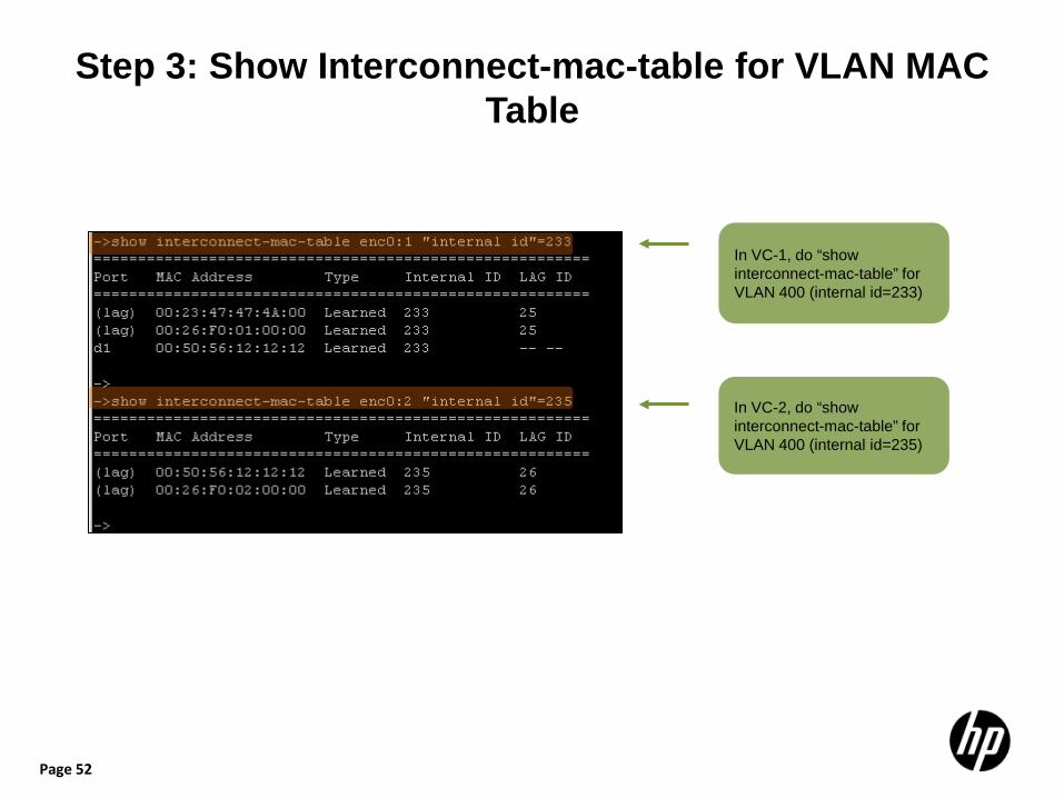
Step 3: Show Interconnect-mac-table for VLAN MAC Table
In VC-1, do “show interconnect-mac-table” for VLAN 400 (internal id=233)
In VC-2, do “show interconnect-mac-table” for VLAN 400 (internal id=235)

Page 53
Nexus5000-1 vPC Configuration and Show Information
Page 54
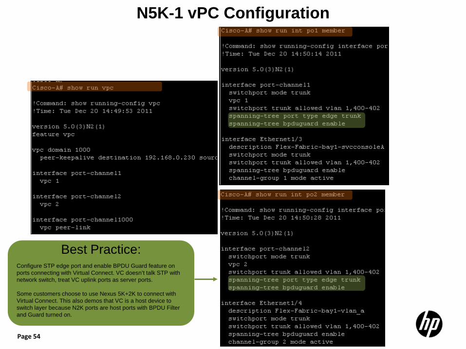
N5K-1 vPC Configuration
Best Practice: Configure STP edge port and enable BPDU Guard feature on ports connecting with Virtual Connect. VC doesn’t talk STP with network switch, treat VC uplink ports as server ports. Some customers choose to use Nexus 5K+2K to connect with Virtual Connect. This also demos that VC is a host device to switch layer because N2K ports are host ports with BPDU Filter and Guard turned on.
Page 55
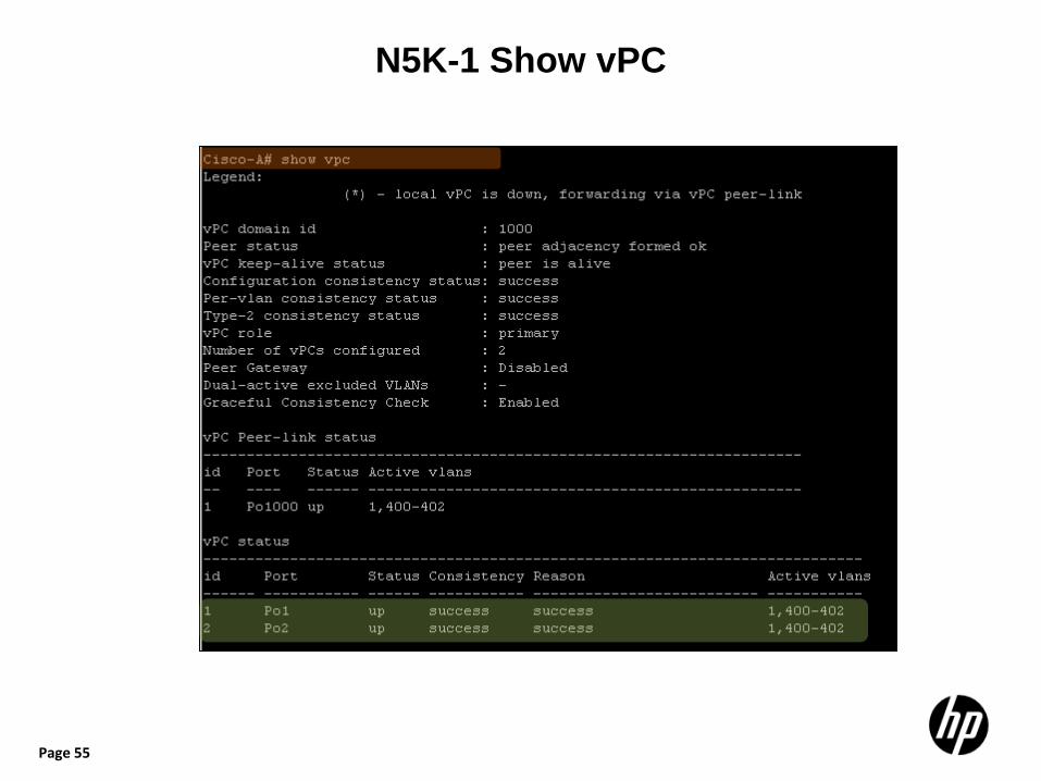
N5K-1 Show vPC
Page 56
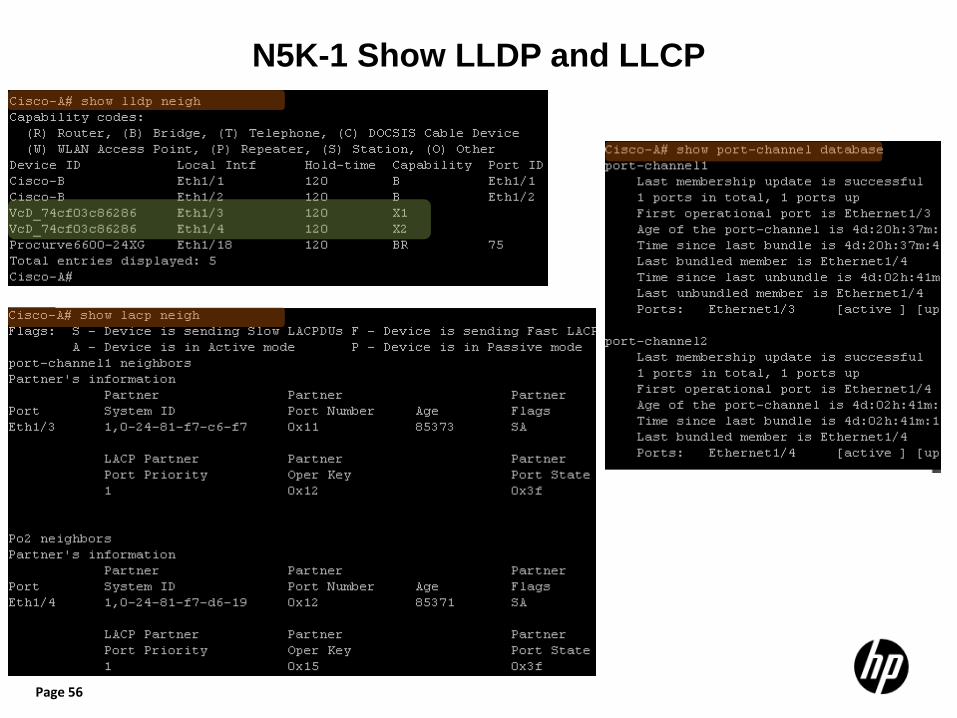
N5K-1 Show LLDP and LLCP
Page 57
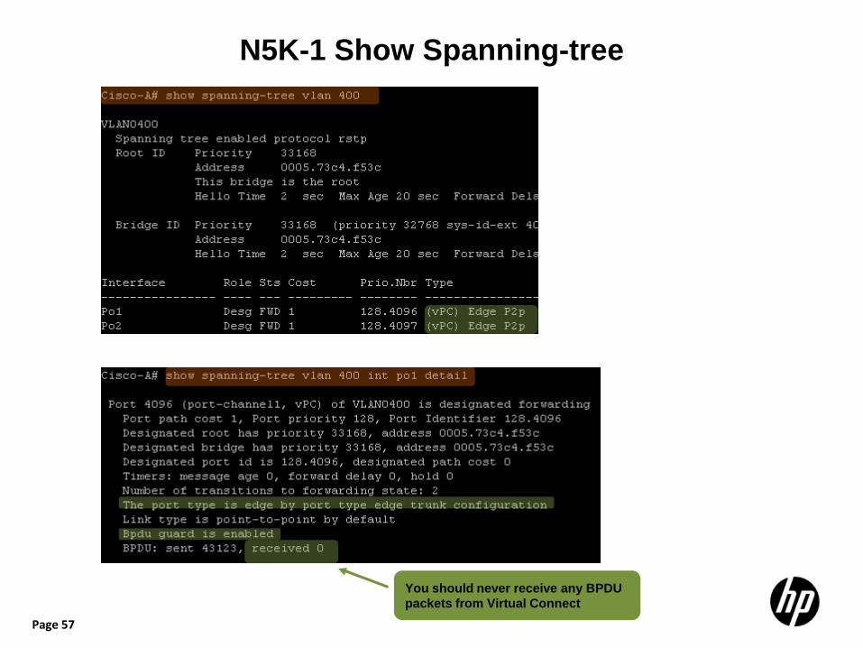
N5K-1 Show Spanning-tree
You should never receive any BPDU packets from Virtual Connect
Page 58
Nexus5000-2 vPC Configuration and Show Information
Page 59
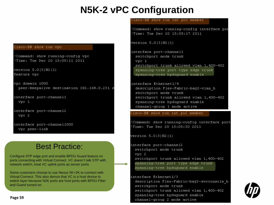
N5K-2 vPC Configuration
Best Practice: Configure STP edge port and enable BPDU Guard feature on ports connecting with Virtual Connect. VC doesn’t talk STP with network switch, treat VC uplink ports as server ports. Some customers choose to use Nexus 5K+2K to connect with Virtual Connect. This also demos that VC is a host device to switch layer because N2K ports are host ports with BPDU Filter and Guard turned on.
Page 60
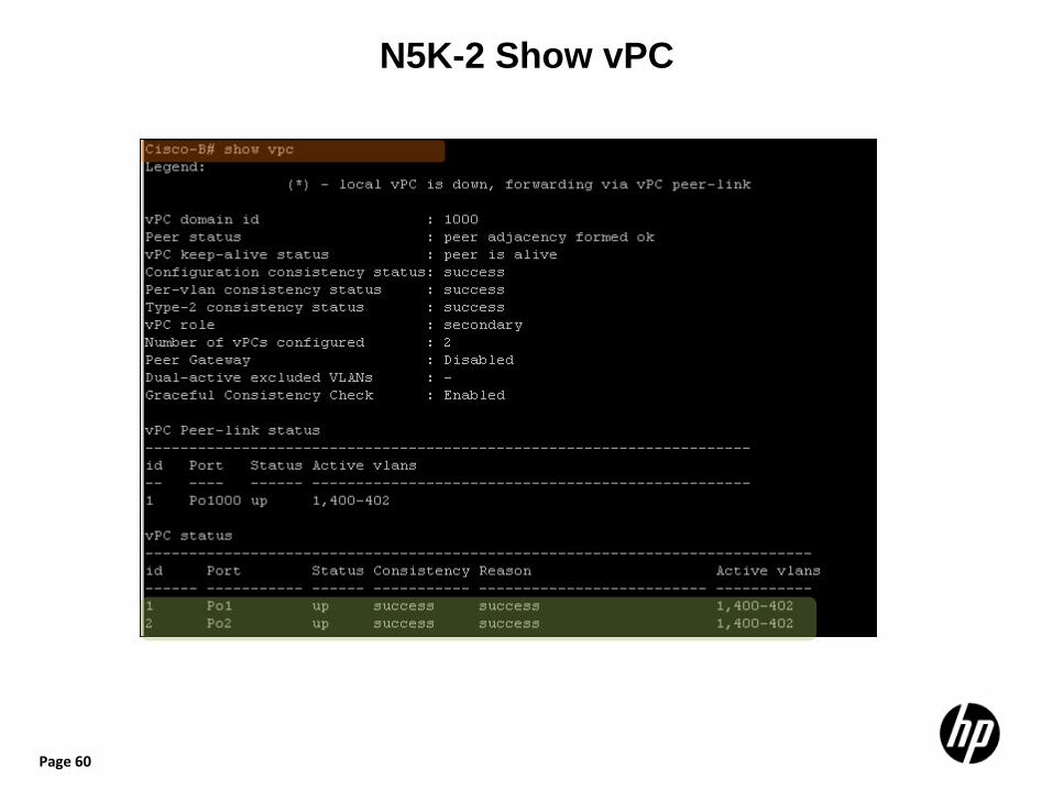
N5K-2 Show vPC

Page 61
N5K-2 Show LLDP and LLCP
Page 62
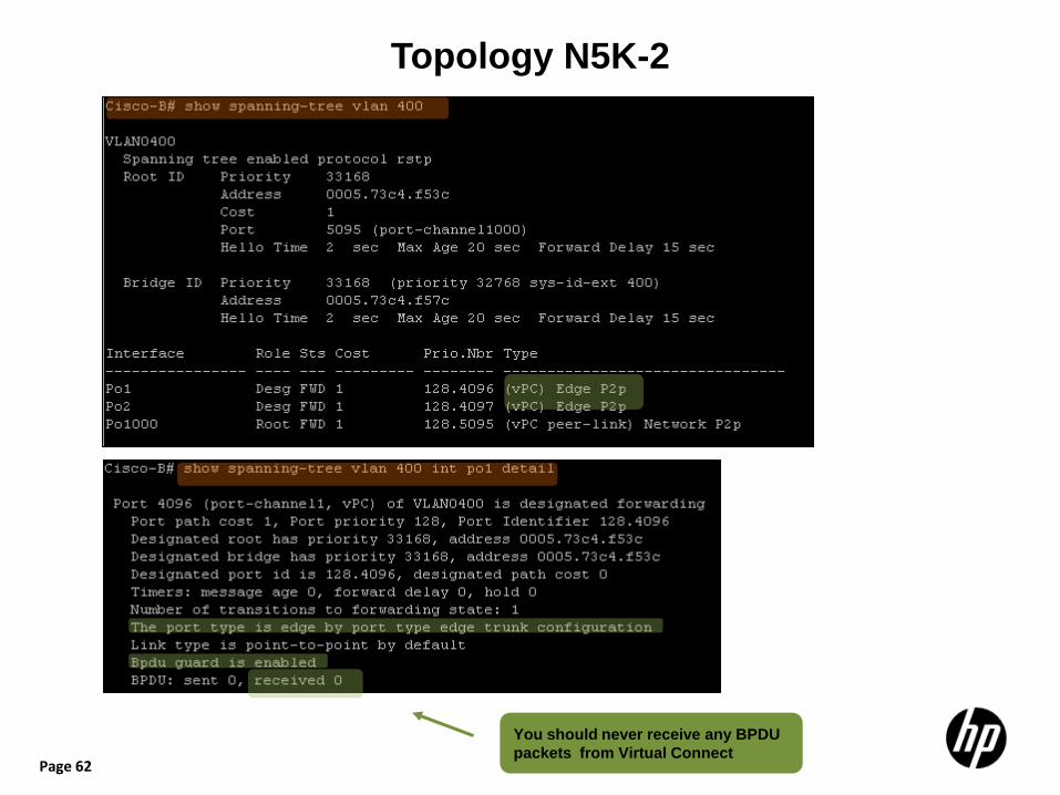
Topology N5K-2
You should never receive any BPDU packets from Virtual Connect
Page 63
Virtual Connect Configuration
Page 64
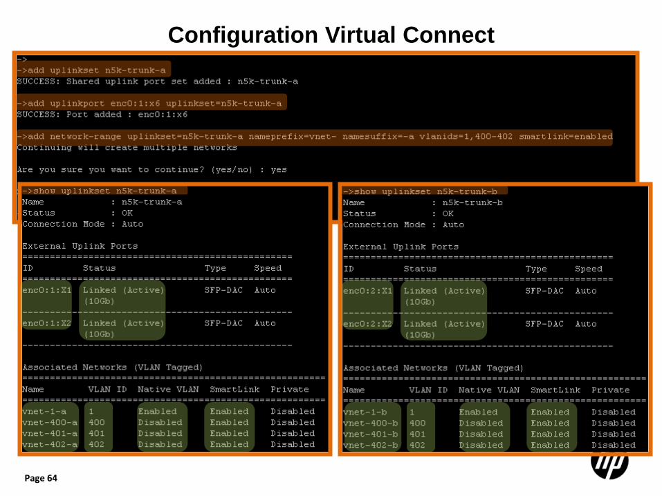
Configuration Virtual Connect
Page 65
References
Virtual Connect Release 3.30 CLI User Guide. http://bizsupport1.austin.hp.com/bc/docs/support/SupportManual/c02996642/c02996642.pdf
Virtual Connect Release 3.30 GUI User Guide http://bizsupport1.austin.hp.com/bc/docs/support/SupportManual/c02996013/c02996013.pdf
Virtual Connect for Cisco Network Administrators http://h20000.www2.hp.com/bc/docs/support/SupportManual/c01386629/c01386629.pdf
Virtual Connect FlexFabric Cookbook http://h20000.www2.hp.com/bc/docs/support/SupportManual/c02616817/c02616817.pdf Note: Virtual Connect configuration examples in GUI mode
Virtual Connect Ethernet Cookbook http://h20000.www2.hp.com/bc/docs/support/SupportManual/c01990371/c01990371.pdf
Virtual Connect and HP Networking Switch IRF Integration Guide http://bizsupport1.austin.hp.com/bc/docs/support/SupportManual/c02843088/c02843088.pdf Note: The same VC design and GUI configuration snapshots also apply to vPC/VSS design.