Embed Size (px)
Citation preview
Sara Costa Antunes
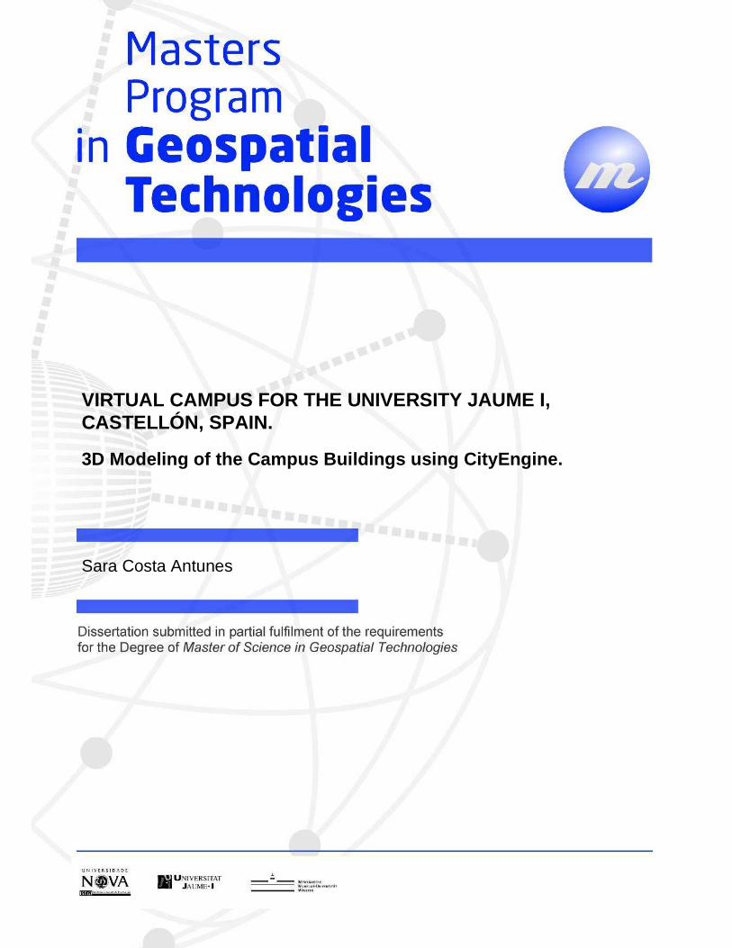
VIRTUAL CAMPUS FOR THE UNIVERSITY JAUME I, CASTELLÓN, SPAIN.
3D Modeling of the Campus Buildings using CityEngin e.

VIRTUAL CAMPUS FOR THE UNIVERSITY JAUME I, CASTELLÓ N, SPAIN. Modeling 3D campus buildings using CityEngine.
2013
Sara Costa Antunes

ii
VIRTUAL CAMPUS FOR THE UNIVERSITY JAUME I, CASTELLÓN, SPAIN.
3D Modeling of the Campus Buildings using CityEngine.
Dissertation supervised by
Michael Gould, PhD
Escuela Superior de Tecnologías y Ciencias Experimentales
University Jaume I, Castellón, Spain
Dissertion co-supervised by
Joaquín Huerta, PhD
Escuela Superior de Tecnologías y Ciencias Experimentales
University Jaume I, Castellón, Spain
Pedro Cabral, PhD
Instituto de Estatística e Gestão de Informação
Universidade Nova de Lisboa, Lisboa, Portugal
February 2013

iii
ACKNOWLEDGMENTS
I wish to thank, first and foremost, my supervisors, Professors Michael Gould,
Joaquín Huerta and Pedro Cabral for their support and most of all, for introducing me
this wonderful and exciting project – the ViscaUji Smart Campus.
I would like to thank others within the GeoTech Master Department of the University
Jaume I for their advice and guidance in the development of this project.
To my fellow Geospatial Technologies colleagues and to all my friends back home
that cared for me and always provided support and confidence throughout this Master
course.
Thank you to my parents who have been an authentic proof of eternal love and
support throughout my life.
Thank you Kristinn for your presence and constant support. It was a pleasure to
work with you.
Finally thank you to the Master Geotech consortium for giving me this
opportunity and life experience that I will never forget.
iv
VIRTUAL CAMPUS FOR THE UNIVERSITY JAUME I, CASTELLÓ N, SPAIN.
3D Modeling of the Campus Buildings using CityEngine.
ABSTRACT
The Virtual Smart Campus for the University of Jaume I – Visca Uji – is a project
that aims to transform the University of Jaume I (UJi) into a “Smart Campus”. Several
applications are part of the Smart Campus such as Uji Place Finder, Energy
Consumption, Routes, Resources Management, and Indoor Mapping. Part of this
project is the creation of the 3D model of the university buildings using Esri software —
City Engine.
This study analysed two 3D modeling approaches: procedural modeling language
(CGA Shape) and manual modeling. The first, Computer Generated Architecture (CGA)
shape is an extension of set grammars that have been applied in CG successfully over
the years. And the second, CityEngine offers a set of shape creation and editing tools
that allows a more intuitive and pragmatic 3D modeling technique. Both approaches
have advantages and disadvantages, overall creating a 3D model by using procedural
modelling language showed to be the more efficient and pragmatic method.

v
KEYWORDS
Smart Campus
Smart Cities
3D GIS
Geovisualization
Computer Generated Architecture
Procedural Modeling
CGA Shape Grammar
Texturing

vi
ACRONYMS
UJI University Jaume I VISCAUJI Virtual Smart Campus for the University Jaume I ESRI Environmental Systems Research Institute CAD Computer-aided design XML Extensible Markup Language GML Geographic Markup Language KML Keyhole Markup Language CGA Computer Generated Architecture CEJ CityEngine Scene File WebGL Web-based Graphics Language
vii
TABLE OF CONTENTS
1 INTRODUCTION ................................................................................................................... 1
1.1 Theoretical Framework ..................................................................................................... 3
1.1.1 From 2D to 3D GIS ................................................................................... 3 1.1.2 Online Geovisualization and Standards ...................................................... 5 1.1.3 CGA and 3D Real World Representations ................................................. 6
1.2 Motivations and Objectives ............................................................................................... 8
2 METHODOLOGY ................................................................................................................ 10
2.1 The Campus .................................................................................................................... 12
2.2 Software and Data ........................................................................................................... 13
2.3 Production Process .......................................................................................................... 17
2.4 Procedural Modeling ....................................................................................................... 18
2.4.1 ESTCE Building ...................................................................................... 21 2.4.2 The Students Residence Building ............................................................. 28 2.4.3 Ágora Buildings....................................................................................... 32 2.4.4 The Workshops Building ......................................................................... 34
2.5 Manual Modeling ............................................................................................................ 35
2.5.1 The Sports Building ................................................................................. 37 2.5.2 Paranimfo/Anditorium Building ............................................................... 38
2.6 Texturing the model ........................................................................................................ 39
2.6.1 Crop Image Tool ...................................................................................... 40 2.6.2 Static Texturing Tool ............................................................................... 41
2.7 Model Export and Integration .......................................................................................... 42
3 DISCUSSION ....................................................................................................................... 45
4 CONCLUSION ..................................................................................................................... 47
4.1 Future Work .................................................................................................................... 48
BIBLIOGRAPHIC REFERENCES ............................................................................................. 50
Annex 1: CGA Rule File for the ESTCE Building. ................................................................... 54
Annex 2: CGA Rule File for the Students Residence Building .................................................. 60
Annex 3: CGA rule file for the Workshops building ................................................................. 64
Annex 4: CGA rule file for the Ágora buildings ........................................................................ 67

viii
INDEX OF TABLES Table 1: CityEngine’s user analysis applied to this study……………………………45
ix
INDEX OF FIGURES
Figure 1: Flowchart of the methodology used in this study. 10 Figure 2: Campus area in CityEngine with the finalized 3D buildings. ........................ 12
Figure 3: Esri Local Government Information Model applied to ViscaUJi project
(Sanchis & Arnal & Molina & Sanchis & Díaz & Huerta & Gould, 2012). ........... 14 Figure 4: CityEngine ViscaUji File System. On the left image, the Scene view and on
the right image the Navigator view. ...................................................................... 15 Figure 5: View of the CGA rule file in the CGA rule editor window and on the right, the
schematic view of the rule. ................................................................................... 16 Figure 6: The Inspector Window for the Ágora CGA rule file. .................................... 17
Figure 7: The scope of a shape. The point P, together with the three axis X, Y, and Z and
a size S define a box in space that contains the shape (Muller & Parish& Haegler & Ulmer &Van Gool, 2006). .................................................................................... 19
Figure 8: CGA rule like shape tree. ............................................................................. 20 Figure 9: ESTCE building located on the southwest corner of the Campus. (Departament
de Matemàtiques. ESTCE. Universitat Jaume I, January 2013. http://www.deptmat.uji.es/). ................................................................................. 21
Figure 10: CityEngine Web Scene 3D Model of the ESTCE building. ......................... 21
Figure 11: Image on the left: Wireframe on shaded/textured view of the 3D building and
subdivision of the footprint. Image on the right: Back side of the building. ........... 22
Figure 12: On the right, the output of the “Comp.index”o peration. The left image shows
discontinued facade. ............................................................................................. 23 Figure 13: On the right, CityEngine Web Scene detailed view of ESTCE's South
Facade. On the left, a Split Operation along the Y axis on a basic facade design. .. 26
Figure 14: On the right, CityEngine Web Scene detailed view of ESTCE's South
Facade. The image on the left is the Split Operation along the X axis, in a basic facade design. ....................................................................................................... 27
Figure 15: On the left North West view of the Residence. (tuestudios.com. Residencia
Universitaria Campus – Castellón. January 2013. http://www.tusestudios.com/content/residencia-universitaria-campus-castellon-2). On the right image: South view of the Residence. (Jiménez, Olivia. oidocozina.blogspot.com.es. May2012.January2013. http://oidocozina.blogspot.com.es/2012/05/independencia-universitaria.html) ...... 28
x
Figure 16 : CityEngine Web Scane 3D model representation of the North West and South facades of the Student’s Residence Building. .............................................. 28
Figure 17: On the left image: CityEngine Web Scene view of the West facade 3D
Model. On the right, SideFacade Rule, split along the y axis on a basic facade design. .................................................................................................................. 30
Figure 18: Ground Floor rule on a basic facade design. ............................................... 30
Figure 19: CityEngine Web Scene model of the railings on the main entrance of the
Student’s Residence building. ............................................................................... 31 Figure 20: CityEngine Web Scene of the Ágora buildings. .......................................... 32
Figure 21: Discontinued facades in Ágora buildings in CityEngine.............................. 32
Figure 22: CityEngine Web Scene of the Agora West facade 3D model. ..................... 33
Figure 23: Basic facade design for the rules A, K and WindowFrame of the West facade
in the Agora buildings. .......................................................................................... 33 Figure 24: CityEngine Web Scene of the 3D Workshops building model..................... 34
Figure 25: Creating and Editing shapes manually toolbar in CityEngine (CityEngine
Help, 2011). .......................................................................................................... 35 Figure 26: Examples created on the fly to show the usage of the polygon shape
modeling tools in the ViscaUJi CityEngine scene. ................................................. 36
Figure 27: The image on the left is the CityEngine Web Scene of the 3D model of the
entrance facade of the Sports building. On the right, a photograph from the Sports building. (Arqa.com. Pabellón polideportivo de la Universidad Jaume I de Castellón. November 2004. January 2013. http://arqa.com/arquitectura/internacional/pabellon-polideportivo-de-la-universidad-jaume-i-de-castellon.html) ................................................................. 37
Figure 28: CityEngine Web Scene 3D Sports Building model. .................................... 37
Figure 29: On top a photograph of the Auditorium (Castellon Convention Bureau -
Turismo y negocios en Castellon. 2010. January 2013. http://www.castelloncongresos.com/web/index.php?option=com_onestabliments&task=listTipo&id=21&Itemid=33). And below, CityEngine Web Scene from the Auditorium building. ............................................................................................ 38
Figure 30: CityEngine’s Crop Image tool. On the left side a photograph as input and on
the right the result output. ..................................................................................... 40 Figure 31: Use of City Engine’s Shape Texturing Tool in the Auditorium Building. .... 41

xi
Figure 32: Autodesk 3D Studio Max university buildings. On the left, the Humanities Faculty and on the right, the Library. (Geotech, Uji Data) ..................................... 43
Figure 33: Autodesk 3D Studio Max university buildings: on the left image the
Technology & Experimental Sciences building and on the right the Economics Faculty. (Geotech, Uji Data) ................................................................................. 44

1
1 INTRODUCTION
The University Jaume I (Uji) is one of the major research institution located in the
Valencian Community, Spain. Created in 1991 is a public institution of higher education
and research which aims for the social, economic and cultural development of the city of
Castellón, in particular. UJi is a vibrant, competitive and enterprising university.
The development of a strategic plan and the formalization of their image and
communication policy, endorse UJi as an entity that is committed to quality and
transparent management, with a strong social commitment with its surroundings. The
UJi campus, a single and attractive campus allows closer relationships between the
different faculties and their students. Currently UJi has 31 degrees and diplomas courses
available to about 13, 500 students, with 1120 teachers and 640 administrative services
professionals.
In the last couple years, UJi decides to take an important step in their
technological and economical development – the Smart Uji project. Smart UJI means
Smart Campus. A Smart Campus has the goal to provide an interactive map and services
that allows people to visualize, locate and access information about the campus street
network, buildings, classrooms, departments, programs, offices, cafeterias, residence,
green spaces, and so forth. The concept of Smart Campus follows the same principles
than the known Smart Cities concept/policy: find “smart” solutions to provide
quantitative and qualitative improvement of life of the populations, whether to an urban
population or students in a campus.
Smart UJi intends to improve the resources and behaviour management in the
campus and, most of all, aims to produce spatial data and manage information to
optimize the use of all resources related to the campus. Being a university campus a
smaller enclosure than a city, this concept serves real testing ground for the
implementation of real Smart City.
For instance, the development of services and applications supported by a data
gathering platform that integrates real time information systems and intelligent energy
management systems will teach the user to learn how to interact with the building and
thus, the building learns how to interact with the user in a more energy efficient way.
2
At this point, ViscaUJi is a map-based view of interior and/or exterior assets on
the university campus that enables employees, students and visitors to locate an area of
interest and review information stored in the human resources and facilities management
database. In the future, will also allow employees and visitors to deliver a web-based
service request or booking spaces applications and integrate other existing services like
the monitoring of energy consumptions or solid wastes management. (GEOTEC,
Geospatial Technologies Research Group, 2012).
Among the applications for the monitoring and management of resources currently
the prototype incorporates a customer display, based on ESRI map templates, to
visualize and obtain information from all of the campus outdoor spaces (sidewalks,
parks, parking lots, bike routes). As well as specific elements such as trees, different
types of containers residues or spots reserved for bicycle parking.
With the finalization of this project the prototype will be updated into a 3D scene.
All the campus buildings, street network and all the outdoor spaces as well as, indoor
spaces will be displayed in a near future in 3D, hopefully.
Nowadays, more and more people are increasingly becoming familiar with 3D
visualization of the earth's surface, for instance Google Maps or/and Google Earth.
GIS applications such as ArcGIS are taking full advantage of these capabilities
and empowering their software with 3D tools.
Using 3D building models is extremely helpful, such models let designers,
architects, and managers virtually walk through a project to get a more intuitive
perspective on their work. They can also check a design’s validity by running computer
simulations of energy, lighting, acoustics, fire, and other characteristics and thereby
modify or adjust designs as needed before construction begins.
In brief, this thesis will focus on the procedure of the 3D creation of the first
university buildings using the new Esri software – CityEngine.
It is relevant to mention that the creation of Smart UJi and the 3D data in
CityEngine is quite new and unique. There is only other example that was created in the
same conditions as UJi, which is the Esri Campus in Redlands.
The following chapter reviews some relevant framework.
3
1.1 Theoretical Framework
1.1.1 From 2D to 3D GIS
Over the past 20 years, GIS has become a sophisticated system for maintaining
and analysing spatial and thematic information on spatial objects. From paper maps to
digital cartography, GIS has always been dynamic and in evolution. In the early 90's, the
introduction of 2.5D concept enabled GIS to take on other dimensions and enabled users
to get closer to the real world. The continuous improvements in GIS are allowing us to
visualize the world in a true 3D environment. GIS is no longer 2D, but is now becoming
3D.
3D City Models are digital representations of the Earth’s surface and related
objects belonging to urban areas. The most common use of 3D geovisualisation today is
within public planning, architecture, environmental monitoring and landscape planning.
For instance, museums focus on 3D information for presentations, using its unique
ability for landscape visualisation and for visualising temporal changes. Tourism plays
an increasing role, while the gaming industry keeps geovisualisation under surveillance.
(Nielsen, 2007)
The fact that we are now capable of building 3D City Models in a GIS
environment, is allowing users to overcome some limitations of 2D GIS, such as, noise
prediction models, water flood models, air pollution models, and so forth.
Many disciplines are evolving into 3D. When it comes to scientifically correct
visualisations, like in geovisualisation, the advantages are many. First of all,
Presentation: 3D models are natural and cognitively easier to interpret and are thus more
appropriate to communicate ideas and visions; 2) Exploration: the human vision is made
to quickly interpret a large amount of content or data in a scene. There are relations in a
scene which the human brain perceive, often without being conscious of it; 3)
Immersion: The user can be led through hardware interfaces to get the feeling of
immersion into the scene and thereby to have a strong sense of being in a physical
world. This has been used in adventure oriented models, as well as in product
development of for instance engines; 4) Documentation: Much geographical information
contains height information that are only handled as additional information in 2D; and
4
5) Simulations and dynamics: temporal simulations of 3D data can give new ways of
studying complex processes in nature and society. (Nielsen, 2007)
The improvement of 3D data collection techniques such as aerial and close range
photogrammetry, airborne or ground based laser scanning and GPS are an important
factor for the development of 3D modeling.
The development of laser-scanning has reached a level sufficient for providing
data for realistic 3D geovisualisation modelling, which today is the subject of various
terrain models and automatic object generation.
Among the large GIS companies, ESRI has developed a series of 3D applications,
the ArcGIS 3DAnalyst including ArcGlobe. ArcScene, MapInfo’s Vertical Mapper is
the competitive response to ArcGIS and another type of product is the CAD-related
programs (Nielsen, 2007).
In CAD models such as 3D Studio Max and SketchUp, 3D objects are represented
by vectors as points, lines and polygons in a coordinate system. The CAD models
representations have a high degree of precision and detail therefore they are more
suitable for a limited geographical area. Their use is very popular in architecture and
engineering projects, and not as much for geographical projects. CAD models aren't
very useful for storing associated attributes or topological information and thus are not
useful for analytical tasks.
Other new techniques that push 3D GIS developments are hardware
developments: processors, memory and disk space devices have become more efficient
in processing large data sets, especially graphics cards also used by gaming
industry.(Stoter & Zlatanova, 2003). The advancement in web technologies has greatly
contributed to the successful implementation of 3D City Models to support town
planning, environmental analysis, security and emergency management, as well as many
other applications. (Elwannas, 2011)
5
1.1.2 Online Geovisualization and Standards
Today, we live in an online world. Everything and everyone is online. The web
service has arrived and it is here to stay. Nowadays it is possible to image when asked
about where a certain place is located to go a bookshelf and open up your world atlas?
Most probably, you will use Google Maps.
Nowadays, geobrowsers such as Google maps, Google Earth, Bing maps among
others revolutionary the way we see the world their ever growing popularity is due to
easy access from the users and the ability to visualize large geographical areas. Online
map services allow the user to visualize, interact and search for spatial information,
using high quality aerial photographs.
Google Maps offers Street View that allows the user to visualize and explore
places and geographical areas around the world through 360-degree street-level
imagery. Bing Maps offers the Birds Eye view that allows the user to visualize the scene
from above, as if the user is a bird, gaining an elevated view from the object below.
In that sense, for many years, virtual globes were mostly seen as pleasant
visualisation tools, online applications that allow the user to visualize the world as it is.
However, in the last years virtual globes have been introducing 3D models. The
3D web scenes, especially of urban areas, have been developing in an impressive
rhythm. For instance Google Maps offers a free modeling tool to create 3D models of
any place on the globe (SketchUp Google, 2010). SketchUp is a basic, easy and intuitive
program for drawing objects (buildings) and applying textures in a very automatic and
practical way. Still, comparing 3D modeling tools and 3D software programs are out of
the scope of this thesis.
Behind the 3D web geovisualisation, there is a language that defines a set of
rules for encoding documents in a format that is both human-readable and machine. The
most known is XML (Extensible Markup Language). From the large number of XML
standards it is worth to mention the: Geographic Markup (GML) and the Keyhole
Markup Language (KML). GML is a grammar to express geographical features and
KML is a geographic notation and visualization within the web. CityGML and
GoogleEarth are the most known examples.
CityGML not only represents the shape and graphical appearance of 3D
buildings but specifically addresses the object semantics and the thematic properties,
6
taxonomies and aggregations. In the past city models often have been built as purely
graphical 3D models, new applications have information needs beyond visual
characteristics. Besides geometry, semantics and topology of the 3D objects have to be
taken into account in order to enable for thematic queries, analysis tasks, automatic
integration, validity checking, or spatial data mining.
CityGML is an open source modeling language for 3D City Models and a general
information model for the representation of 3D urban objects. Berlin is an example for
having an official 3D model that is based on the CityGML and uses it as the exchange
format between database, editor, and presentation systems.
1.1.3 CGA and 3D Real World Representations
Real world 3D representations such as the ones presented in this study
incorporate representations in a realistic way. The x, y, and z coordinates are mainly
used to show the real world dimensions, elevation and/or the dimensions, including
height of buildings or other objects. Additional details are suggested through photo
texturing of the facades while the details are not explicitly modelled in the underlying
geometric model.
There are variety of approaches based on different data sources and aiming
different resolution and accuracy. Accordingly to Stoter & Zlatanova, there are four
general approaches for creating 3D models:
- Bottom-up: using footprints (from existing 2D maps) and extrude the footprints
with a given height using laser scan data, surveying, GPS or photogrammetry data.
Consequently, this approach has the problem of the detail of roofs cannot be modelled.
This approach is known to be very fast and sufficient for applications that do not need
high accuracy or that don't need roofs, and many details;
- Top-down: using the roof obtained from aerial photographs, airborne laser scan
data and some height information from the ground. This approach on the other hand
emphasises the modeling of the roofs.
- detailed reconstructing of all details. The most common approach is to fit
predefined shapes to the 3D point clouds obtained from laser scan data or 3D edges
extracted from aerial photographs. The advantage of this approach is the full automation
7
and the major disadvantage is that it is very time-consuming since the algorithms used
are very complex. And the last approach is a combination of all of them.
There isn't a general approach, the choice of the method has to take in
consideration the type of project, the type of objects to model (if virtual or real), the data
sources available, as well, as the software and hardware definitions.
When modelling real objects, such as in this project, the details are what makes
the 3D construction/creation labour intensive. Thus, details be adjusted to the
requirements of the application and the time element.
Procedural modeling, based on CGA shape grammars, is a powerful method to
efficiently produce 3D building models. It offers a lightweight semantically meaningful
representation instead of huge mesh files. (Mathias & Martinovic & Weissenbergy &
Van Goo, 2011).
In architecture, shape grammars were successfully used for the construction and
analysis of architectural design. (Bao & Schwarz &Wonka, 2013). CGA Shape has a
standardized description with powerful shape operations while remaining readable to
humans and a commercial tool (CityEngine) exists for rendering 3D models from CGA
Shape rules. The CGA Shape grammar supports a very large number of different
operations and functions in its rules.(Mathias & Martinovic & Weissenbergy & Van
Goo, 2011).
Grammar-based architectural modeling has a long history. Briefly the most
important facts will be exposed.
In 1971, George Stiny in his article Shape Grammars and the Generative
Specification of Painting and Sculpture introduced the idea of shape grammars. In
reality, shape grammars are similar to phrase structure grammars introduced in the
discipline of linguistics. Where phrase structure grammars are defined over an alphabet
of symbols and generate one-dimensional strings of symbols, shape grammars are
defined over an alphabet of shapes and generate n-dimensional shapes. (Stiny & Gips,
1972).
In 2003, a breakthrough came with the introduction of split grammars in the
article “Instant Architecture” by Wonka & Wimmer & Sillion & Ribarsky.
Split grammars are a specialized type of set grammar operating on shapes. Its
suitability for the automatic modeling of buildings stems from the fact that restrictions
8
have been carefully chosen so as to strike a balance between the expressiveness of the
grammar, i.e., the number of different designs it permits, and its suitability for automatic
rule selection. Further development of this idea led to the introduction of CGA Shape, a
shape grammar designed for the procedural generation of large scale urban models.
(Wonka & Wimmer & Sillion & Ribarsky, 2003)
In 2008, Markus Lipp co-created a framework for interactive grammar editing
that lead to a more approachable procedural modeling. With his article, a real-time
interactive visual editing paradigm for shape grammars was introduced, allowing the
creation of rule bases from scratch without text file editing. Shape-grammar based
procedural techniques were successfully applied to the creation of architectural models.
However, those methods are text based, and may therefore be difficult to use for artists
with little computer science background. (Lipp & Wonka & Wimmer, 2008)
In summary, nowadays Shape Grammars are known for their efficiency and
practical methods of creating and modeling urban landscapes. CityEngine procedural
modeling language using shape grammars is a perfect example how the modeling
process of an urban area can be made in a fast and expeditious way.
1.2 Motivations and Objectives
This project main goal is to create 3D data buildings for visualization, model
interaction, and in further development, use the 3D data to perform simulations. As far
as possible, through a virtual scene created by computer generated graphics, the model
must match accurately with the real campus.
Viewing Geospatial data in 3D leads to new insights. We live in a 3D world…so
model and present your data in 3D! (Sengupta, 2011)
The Visca Uji project is a very ambitious and interesting project that surely will
bring more “visibility” to the University Jaume I at a national and international level.
This project is all about integration. Integration of different projects that joined together
will create Smart UJi. Different projects means, as well, different data sources, such as,
2D CAD files, 3D vector, Information Models, Publishing templates, UJI databases,
9
Satellite images, Aerial Photographs, Sensors and Crowdsourcing. This information is
georreferenced, organized and prepared for further integration and publication online.
At this point, the data is published online is: ArcgGis online, ArcGis Server and
ESRI topographic layer. Regarding the applications, so far the UJi Place Finder is
created and operational. This is a brief description about the current status of the
ViscaUJi. Further on the section “Data and Software”, the data structure will be better
explained, as well as, the main properties of CityEngine.
The results of this project will be 3D university buildings that will be used as a
shell to visualize and interact with other applications, for instance, indoor mapping
navigation and/or energy consumption. Additional benefits of using 3D models for
simulations, provides a better platform for generating realistic renderings of new
infrastructure, especially if a temporal context, such as solar or seasonal studies, is
required. 3D city models are also used for security applications such as landslide
prevention or flood simulation.
Using the base information from Uji (Uji database), it will be possible to produce
3D content with a distinctive conceptual design and modeling solution for the efficient
creation of 3D university buildings, streets and exterior spaces (such as trees, urban
furniture and so forth). In addition to the 3D models visualization and user interaction,
this project will produce data – 3D data. That hopefully will be displayed and used as
platform for other applications.
10
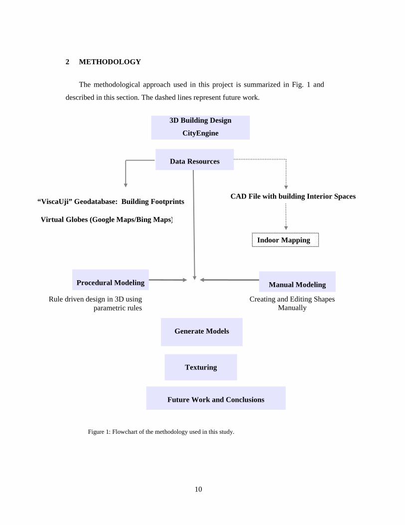
2 METHODOLOGY
The methodological approach used in this project is summarized in Fig. 1 and
described in this section. The dashed lines represent future work.
Figure 1: Flowchart of the methodology used in this study.
Procedural Modeling
Data Resources
Creating and Editing Shapes Manually
CAD File with building Interior Spaces
Rule driven design in 3D using parametric rules
Manual Modeling
3D Building Design
CityEngine
Texturing
Generate Models
Future Work and Conclusions
“ViscaUji” Geodatabase: Building Footprints
Virtual Globes (Google Maps/Bing Maps)
Indoor Mapping
11
The workflow for this project starts with the design of the 3D buildings in
CityEngine. From the moment CityEngine is installed, its learning process begins. It
is important to understand what CityEngine main strength is and what makes it
different. Many materials, tutorials and demos are available on the web and were
crucial for learning how to work with CityEngine.
The next step was the integration of the data resources available for this
project. In the Figure 1, virtual globes are mentioned not as data source, but as online
tools that allow a better perspective of a building. The use of Google Maps, Google
Earth and Bing Maps revealed to be very useful since it allowed the visualization of
the university buildings without having to travel to the campus every other day.
However, Google Maps and/or Google Earth don’t have access to all the streets in the
campus. The simple going around a building was in some cases impossible. On the
other hand, Bing Maps became a good resource, especially with the Bird's Eye view.
The elevated view of the buildings from above gave a good perspective that Google
Maps in some cases, couldn't. On section 2.2 the data resources will be explained with
more detail.
After importing and integrate the source data into CityEngine, the practical
creation of the 3D buildings begin. There are two main methods for the creation of 3D
data: manual modeling and procedural modeling. The main goal is to experiment both
methods, describe them and in the end, compare them. For the procedural modeling
method the university buildings ESTCE, Student's Residence, Workshops and Ágora
were created. And for the manual modeling the chosen buildings were the sports
pavilion and auditorium building. From section 2.3 till section 2.6, a detailed
description of the methods is presented, as well, the explanation of both procedures
applied for each building mentioned previously.
Texturing the model is the last process of the buildings 3D model creation and
consists of assigning digital or photograph textures to the buildings.
Finally, on the final sections of the document an analysis will be made
regarding the both methods, the performance of the software, its main advantages and
disadvantages, as well as, the main contribute of this study.

12
2.1 The Campus
The Uji Campus modeling process includes the design and drawing of the model
in 3D, visualization and adding realism to the made models by applying real facades.
Figure 2: Campus area in CityEngine with the finalized 3D buildings.
The Uji campus is a quite large and ample campus, for that reason and regarding
the deadline factor, is wasn’t possible to model all the buildings in 3D.
The buildings created in 3D were somehow randomly selected. Some reasons
such as, complexity of the building design, facades patterns, and the strategic
importance of the building in the campus were factors on my mind. The buildings
modelled in CityEngine were: the School for Technology and Experimental Sciences
(ESTCE); the Students Residence; the Ágora buildings; the Workshop building; the
Sports centre; and the Auditorium building.
Figure 2 illustrates a final version of the Uji campus in CityEngine.

13
2.2 Software and Data
Esri CityEngine is a 3D modeling software application developed by Esri R&D
Center Zurich (formerly Procedural Inc.). CityEngine was best known for their use of
procedural modeling approach in the creation of urban scenarios for video games and
movies. CityEngine creates urban environments from scratch, based on a hierarchical set
of comprehensible rules that can be extended depending on the user’s needs. (Muller &
Parish, 2001). This approach enables the efficient creation of detailed large-scale 3D
city models, in a less time-consuming period.
Esri CityEngine main advantage is the capability of modeling a complete urban
landscape using a comparatively small set of statistical and geographical input data.
Specifically for this project, the 2D campus building footprints were the only data
needed to simply apply an extrusion operation and apply the rules for the creation of the
3D buildings.
In my opinion, CityEngine is an attempt to unify three major areas:
GIS/Geography, Civil Engineering and Computer Graphics/Design. This means that,
CityEngine was created to combine GIS with computer generated architecture.
CityEngine allows the compilation, use, and manage of geographic information,
including shapefile and file Geodatabase format (ArcGis native formats). As well as,
performing many GIS tasks, such as: mapping, data compilation, analysis, Geodatabase
management, and geographic information sharing (Web/Online).
The ability to easily create 3D urban scenes based on existing GIS data is one of
the key strengths of CityEngine. The software allows you to create high-quality 3D
content using nothing more than a combination of 2D data, attributes, and procedurally
defined rules. This means that any GIS organization will be able to create visually
stunning 3D urban environments using the data they already have. (Muller & Parish,
2001)
The data used for the model creation was organised in a Geodatabase that follow
ESRI model known as Local Government Information Model, a schema-only layer
package containing the schema of the data it references. The content schema was
migrated into a geodatabase design
14
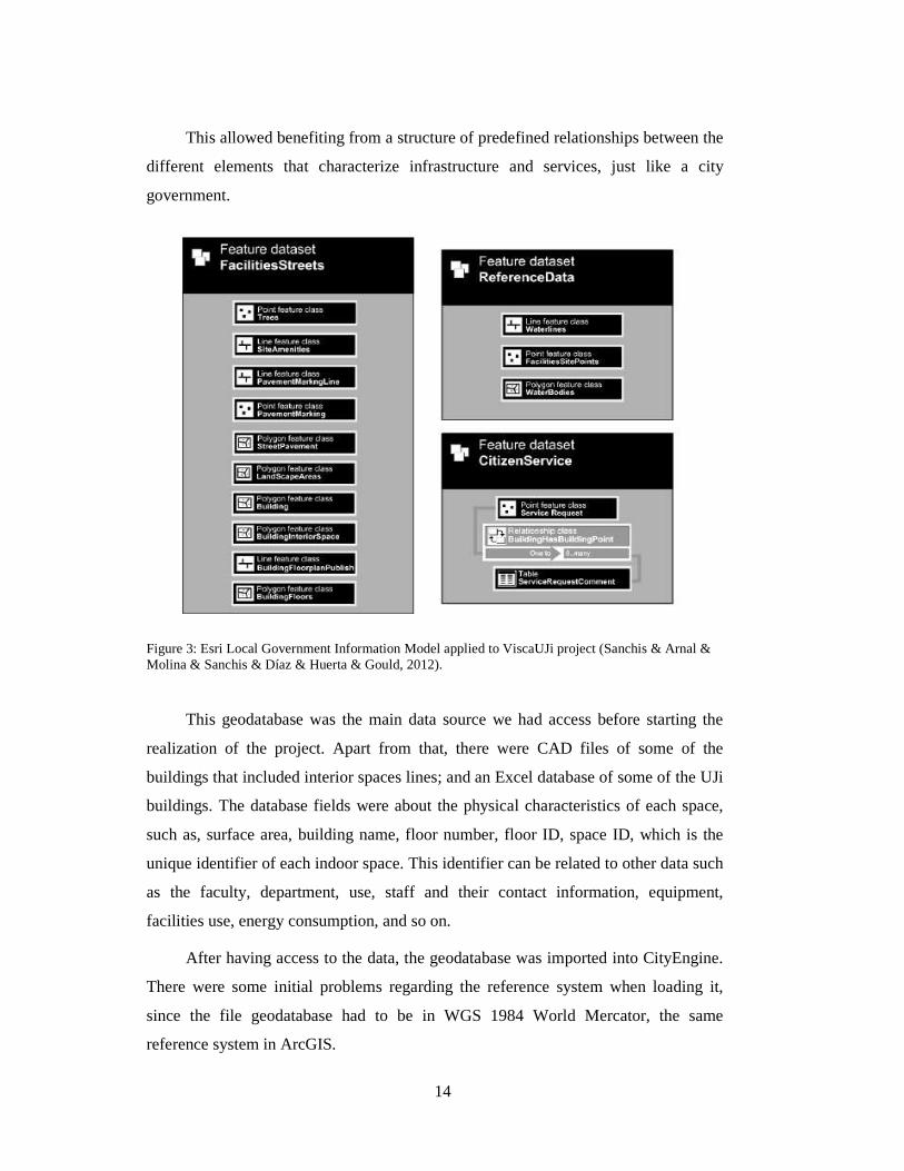
This allowed benefiting from a structure of predefined relationships between the
different elements that characterize infrastructure and services, just like a city
government.
Figure 3: Esri Local Government Information Model applied to ViscaUJi project (Sanchis & Arnal & Molina & Sanchis & Díaz & Huerta & Gould, 2012).
This geodatabase was the main data source we had access before starting the
realization of the project. Apart from that, there were CAD files of some of the
buildings that included interior spaces lines; and an Excel database of some of the UJi
buildings. The database fields were about the physical characteristics of each space,
such as, surface area, building name, floor number, floor ID, space ID, which is the
unique identifier of each indoor space. This identifier can be related to other data such
as the faculty, department, use, staff and their contact information, equipment,
facilities use, energy consumption, and so on.
After having access to the data, the geodatabase was imported into CityEngine.
There were some initial problems regarding the reference system when loading it,
since the file geodatabase had to be in WGS 1984 World Mercator, the same
reference system in ArcGIS.
15
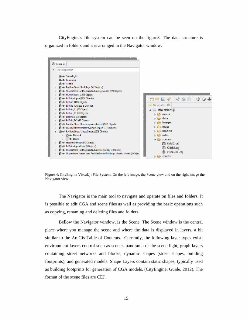
CityEngine's file system can be seen on the figure3. The data structure is
organized in folders and it is arranged in the Navigator window.
Figure 4: CityEngine ViscaUji File System. On the left image, the Scene view and on the right image the Navigator view.
The Navigator is the main tool to navigate and operate on files and folders. It
is possible to edit CGA and scene files as well as providing the basic operations such
as copying, renaming and deleting files and folders.
Bellow the Navigator window, is the Scene. The Scene window is the central
place where you manage the scene and where the data is displayed in layers, a bit
similar to the ArcGis Table of Contents. Currently, the following layer types exist:
environment layers control such as scene's panorama or the scene light; graph layers
containing street networks and blocks; dynamic shapes (street shapes, building
footprints), and generated models. Shape Layers contain static shapes, typically used
as building footprints for generation of CGA models. (CityEngine, Guide, 2012). The
format of the scene files are CEJ.
16
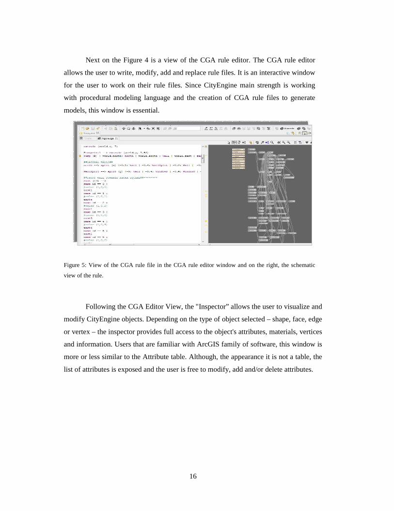
Next on the Figure 4 is a view of the CGA rule editor. The CGA rule editor
allows the user to write, modify, add and replace rule files. It is an interactive window
for the user to work on their rule files. Since CityEngine main strength is working
with procedural modeling language and the creation of CGA rule files to generate
models, this window is essential.
Figure 5: View of the CGA rule file in the CGA rule editor window and on the right, the schematic
view of the rule.
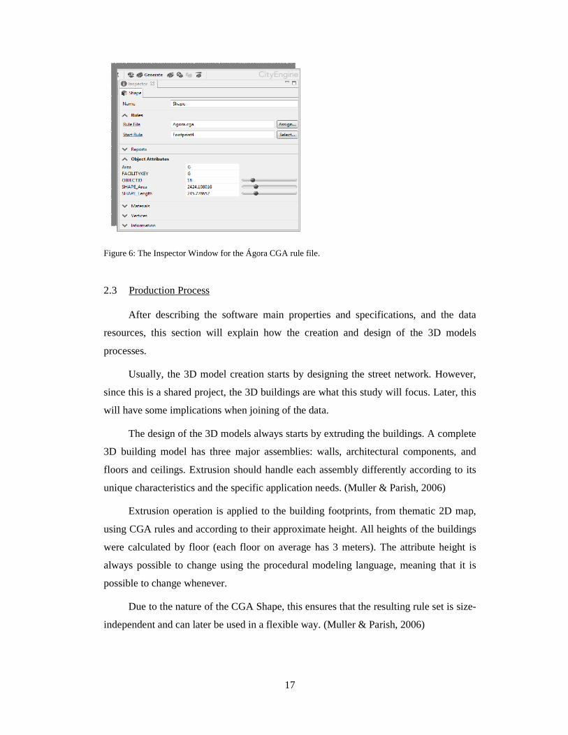
Following the CGA Editor View, the "Inspector” allows the user to visualize and
modify CityEngine objects. Depending on the type of object selected – shape, face, edge
or vertex – the inspector provides full access to the object's attributes, materials, vertices
and information. Users that are familiar with ArcGIS family of software, this window is
more or less similar to the Attribute table. Although, the appearance it is not a table, the
list of attributes is exposed and the user is free to modify, add and/or delete attributes.
17
Figure 6: The Inspector Window for the Ágora CGA rule file.
2.3 Production Process
After describing the software main properties and specifications, and the data
resources, this section will explain how the creation and design of the 3D models
processes.
Usually, the 3D model creation starts by designing the street network. However,
since this is a shared project, the 3D buildings are what this study will focus. Later, this
will have some implications when joining of the data.
The design of the 3D models always starts by extruding the buildings. A complete
3D building model has three major assemblies: walls, architectural components, and
floors and ceilings. Extrusion should handle each assembly differently according to its
unique characteristics and the specific application needs. (Muller & Parish, 2006)
Extrusion operation is applied to the building footprints, from thematic 2D map,
using CGA rules and according to their approximate height. All heights of the buildings
were calculated by floor (each floor on average has 3 meters). The attribute height is
always possible to change using the procedural modeling language, meaning that it is
possible to change whenever.
Due to the nature of the CGA Shape, this ensures that the resulting rule set is size-
independent and can later be used in a flexible way. (Muller & Parish, 2006)
18
Each building in Uji is complex and composed by different and multi geometries.
In some cases, the buildings have different types of textures or colours in their facades.
During my learning process of CityEngine, it was decided to apply a rule per
building. Somehow, this goes against the main “power” of this software, since City
Engine’s strength relies on generating city landscapes using one CGA rule file.
However, a single rule file was applied for each building, since each building at UJi is
unique, from an architectural perspective. CityEngine is use best for huge masses of
buildings which obey the same rules; it is not really the best tool to recreate individual
real world buildings. (Matthias Buehler, ESRI Senior)
2.4 Procedural Modeling
Procedural modeling language can simply be defined as a programming language
that uses algorithms/ rules – CGA shape grammar rules. CGA shape, a novel shape
grammar for the procedural modeling of CG architecture, produces building shells with
high visual quality and geometric detail. (Muller & Parish& Haegler & Ulmer &Van
Gool, 2006)
The CGA shape grammar is defined by four components: a finite set of shapes; a
finite set of attributes; a finite set of operations; and a finite set of production rules.
A shape consists of a symbol (string), geometry (geometric attributes) and
numeric attributes. Shapes are identified by symbols, usually a string.
Geometric attributes correspond to the scope, an oriented bounding box in space
(Figure 6). The most important geometric attributes are the position P, three orthogonal
vectors X, Y, and Z, describing a coordinate system, and a size vector S. These
attributes define an oriented bounding box in space called scope. (Muller & Parish&
Haegler & Ulmer &Van Gool, 2006)

19
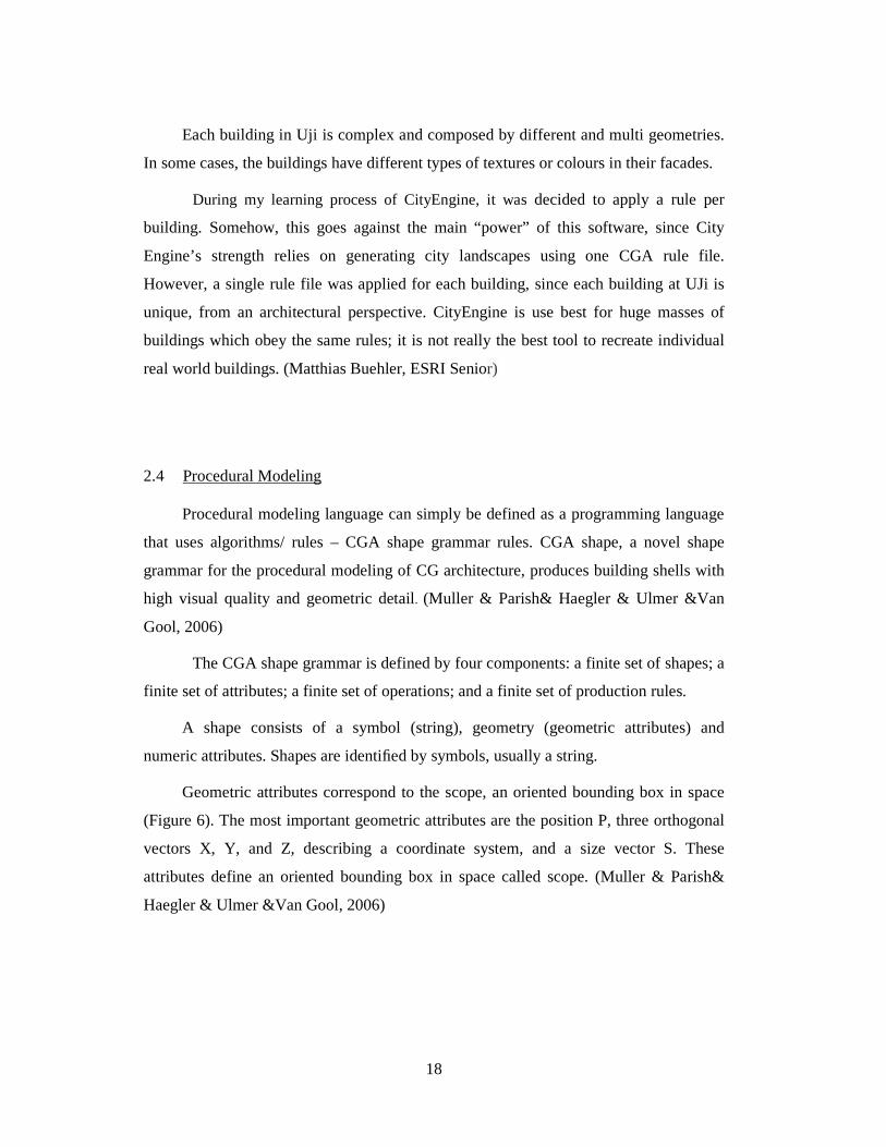
Figure 7: The scope of a shape. The point P, together with the three axis X, Y, and Z and a size S define a box in space that contains the shape (Muller & Parish& Haegler & Ulmer &Van Gool, 2006).
Shape Operations are a very important component in the shape grammar and there
are essentially four types. First, the Scope operations modify the scope of a given shape
and include translation, rotation, and resizing. The Split operations split the scope along
a given axis, with split sizes as attributes. The Repeat operations repeat a shape in a
given direction as long as there is enough space. In CGA Shape they are written as a
part of a split rule. For example, a window gets repeated over the whole length of a
floor. And lastly, the Component split operation splits 3D scopes into shapes of lesser
dimension, e.g. faces, edges, or vertices. (Mathias & Martinovic & Weissenbergy &
Van Goo, 2011).
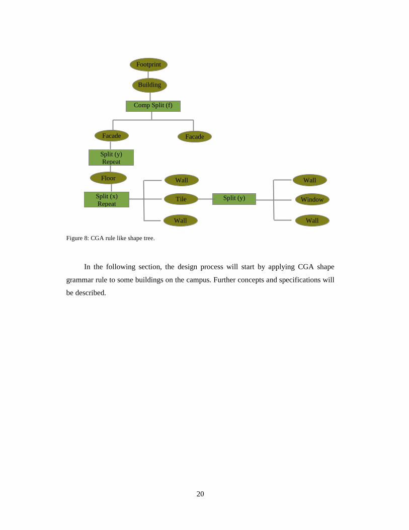
Shape grammar rules modify and replace shapes. Iteratively evolve and develops a
design by adding more and more details (wall, floors, windows, doors). The model
production usually starts from an initial shape, which is most commonly a building
footprint. This shape is gradually refined as rules are successively applied.
In summary, the example of the shape grammar is a tree-like structure. Its nodes
represent shapes, split, component split and repeat operations, capturing the structure of
the building. The process begins with the extraction of shape symbols, and their
classification as terminal or non-terminal shape symbols. In the next step, the rule set is
analyzed, creating the tree structure.
20
Figure 8: CGA rule like shape tree.
In the following section, the design process will start by applying CGA shape
grammar rule to some buildings on the campus. Further concepts and specifications will
be described.
Footprint
Building
Comp Split (f)
Facade
Split (y) Repeat
Floor
Split (x) Repeat
Facade
Wall
Wall
Tile Split (y)
Wall
Wall
Window
21
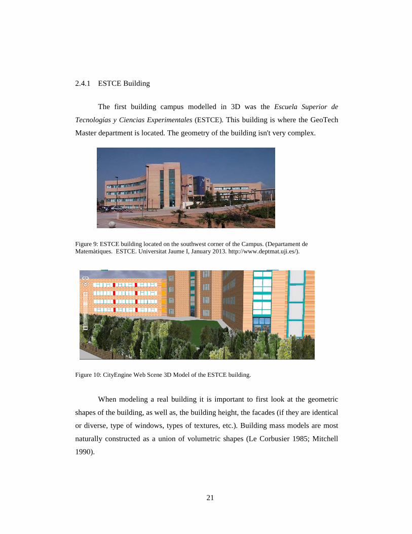
2.4.1 ESTCE Building
The first building campus modelled in 3D was the Escuela Superior de
Tecnologías y Ciencias Experimentales (ESTCE). This building is where the GeoTech
Master department is located. The geometry of the building isn't very complex.
Figure 9: ESTCE building located on the southwest corner of the Campus. (Departament de Matemàtiques. ESTCE. Universitat Jaume I, January 2013. http://www.deptmat.uji.es/).
Figure 10: CityEngine Web Scene 3D Model of the ESTCE building.
When modeling a real building it is important to first look at the geometric
shapes of the building, as well as, the building height, the facades (if they are identical
or diverse, type of windows, types of textures, etc.). Building mass models are most
naturally constructed as a union of volumetric shapes (Le Corbusier 1985; Mitchell
1990).
22
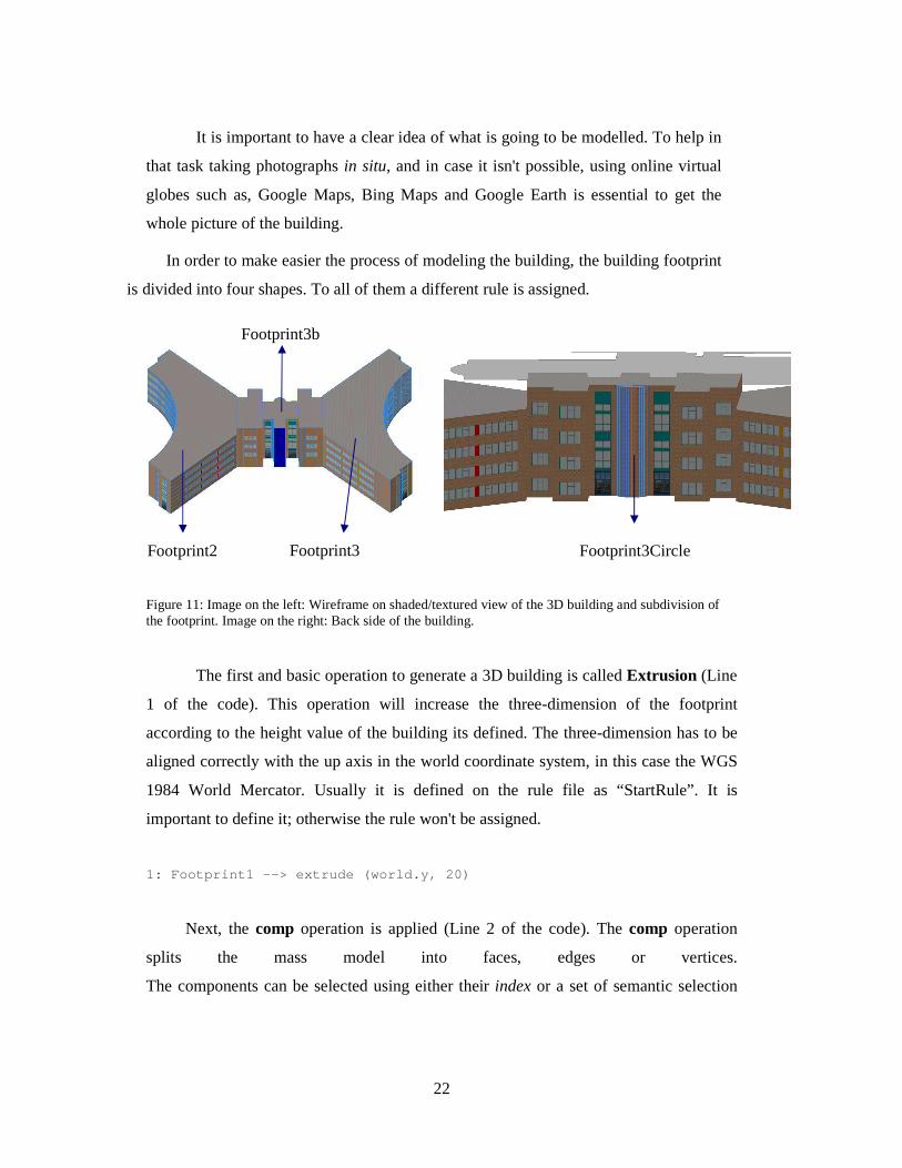
It is important to have a clear idea of what is going to be modelled. To help in
that task taking photographs in situ, and in case it isn't possible, using online virtual
globes such as, Google Maps, Bing Maps and Google Earth is essential to get the
whole picture of the building.
In order to make easier the process of modeling the building, the building footprint
is divided into four shapes. To all of them a different rule is assigned.
Figure 11: Image on the left: Wireframe on shaded/textured view of the 3D building and subdivision of the footprint. Image on the right: Back side of the building.
The first and basic operation to generate a 3D building is called Extrusion (Line
1 of the code). This operation will increase the three-dimension of the footprint
according to the height value of the building its defined. The three-dimension has to be
aligned correctly with the up axis in the world coordinate system, in this case the WGS
1984 World Mercator. Usually it is defined on the rule file as “StartRule”. It is
important to define it; otherwise the rule won't be assigned.
1: Footprint1 --> extrude (world.y, 20)
Next, the comp operation is applied (Line 2 of the code). The comp operation
splits the mass model into faces, edges or vertices.
The components can be selected using either their index or a set of semantic selection
Footprint3
Footprint3b
Footprint3Circle Footprint2
23
keywords. The selected components are transformed to a new shape and processed by a
sequence of shape operations.
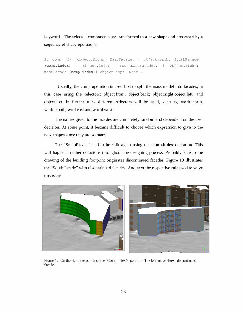
2: comp (f) {object.front: EastFacade. | object.bac k: SouthFacade
( comp.index) | object.left: SouthEastFacade1. | object.right:
WestFacade ( comp.index)| object.top: Roof }
Usually, the comp operation is used first to split the mass model into facades, in
this case using the selectors: object.front; object.back; object.right;object.left; and
object.top. In further rules different selectors will be used, such as, world.north,
world.south, worl.east and world.west.
The names given to the facades are completely random and dependent on the user
decision. At some point, it became difficult to choose which expression to give to the
new shapes since they are so many.
The “SouthFacade” had to be split again using the comp.index operation. This
will happen in other occasions throughout the designing process. Probably, due to the
drawing of the building footprint originates discontinued facades. Figure 10 illustrates
the “SouthFacade” with discontinued facades. And next the respective rule used to solve
this issue.
Figure 12: On the right, the output of the “Comp.index”o peration. The left image shows discontinued facade.

24
3: SouthFacade(id) --> 4: case id == 0 5: color (1,0,0) 6: SouthEastFacade1. 7: case id == 1 : 8: color (1,0,0) 9: texture 10: case id == 11 : 11: color (1,0,0) 12: Shape11. 13: case id == 12 : 14: color (1,0,0) 15: ShapeLateralWindow2. 16: case id == 13 : 17: color (1,0,0) 18: texture 19: else: 20: SouthFacadeComplete.
The comp.index is a zero-based index that assigns an index to each shape that
composes the facade. This operation allows the user to subdivide the facades in many
shapes as possible and work on them individually. The “color” operation was used to
identify the right facade while working on it.
Once the facades are correctly split, it is possible to apply textures whether is a
simple wall or a facade with floors and then windows. Either way, it is important to
specify in the code the correct path of the textures to be used. Usually, all the texture
files (jpg., png., etc.) are located on the folders images and/or assets. This location isn't
mandatory. In the CGA rule file, the textures are usually written in the beginning of the
code.
TEXTURES MainTexture = "assets/facades_uji/ladrillo_caravist a_det.png" WindowTexture = "assets/facades_uji/VENHO_TI.jpg" MidTileTextureRed = "assets/facades_uji/GRANATE MAT E.jpg" SideWindowTexture = "assets/facades_uji/VENHOC_TI_c ropped.jpg" LateralWindowTexture ="assets/facades_uji/VEN.jpg" UjiBlueTexture = "assets/facades_uji/MORADO UJI.jpg " GreenTileTex = "assets/facades_uji/VERDE UJI.jpg" DoorESTCE = "images/DoorESTCE.jpg"
Usually in the beginning of the design process, the textures for the wall, windows
and doors are the first rules to be created. This will be important since when applying
the rules for creating floors, windows and doors, the textures are already created. Below,
on lines 10 to 18 the rule for the wall texture and the window is created.
25
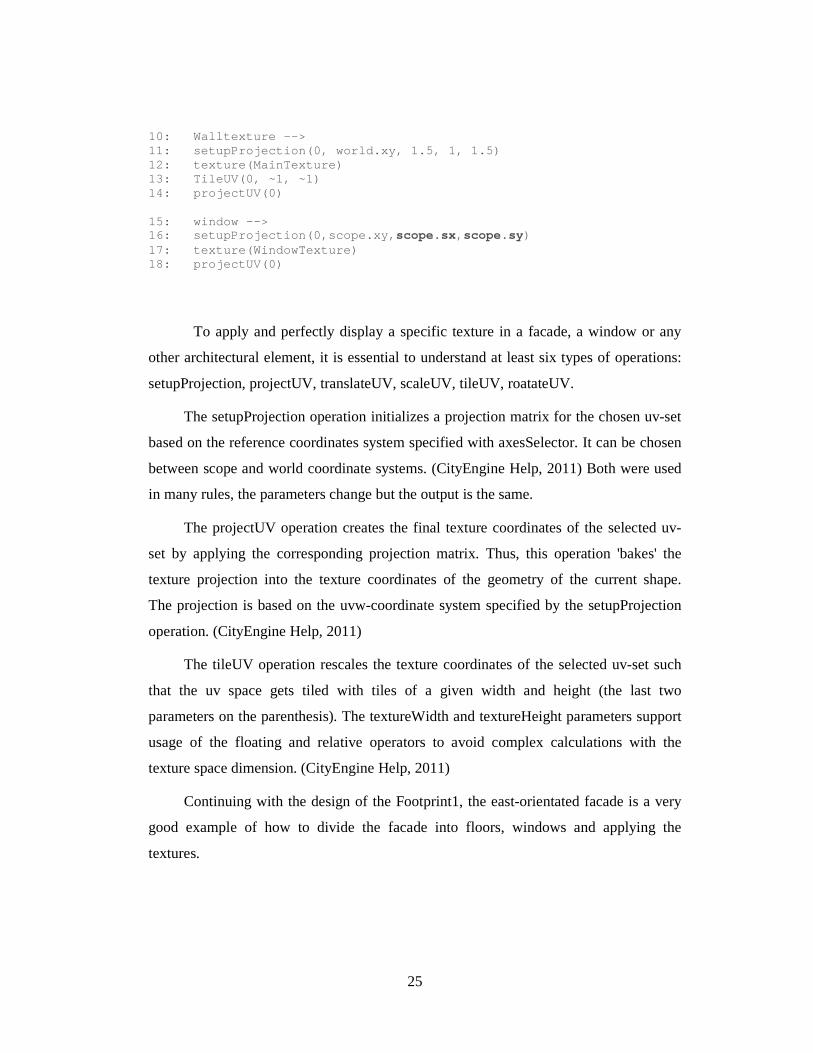
10: Walltexture --> 11: setupProjection(0, world.xy, 1.5, 1, 1.5) 12: texture(MainTexture) 13: TileUV(0, ~1, ~1) 14: projectUV(0) 15: window --> 16: setupProjection(0,scope.xy, scope.sx, scope.sy) 17: texture(WindowTexture) 18: projectUV(0)
To apply and perfectly display a specific texture in a facade, a window or any
other architectural element, it is essential to understand at least six types of operations:
setupProjection, projectUV, translateUV, scaleUV, tileUV, roatateUV.
The setupProjection operation initializes a projection matrix for the chosen uv-set
based on the reference coordinates system specified with axesSelector. It can be chosen
between scope and world coordinate systems. (CityEngine Help, 2011) Both were used
in many rules, the parameters change but the output is the same.
The projectUV operation creates the final texture coordinates of the selected uv-
set by applying the corresponding projection matrix. Thus, this operation 'bakes' the
texture projection into the texture coordinates of the geometry of the current shape.
The projection is based on the uvw-coordinate system specified by the setupProjection
operation. (CityEngine Help, 2011)
The tileUV operation rescales the texture coordinates of the selected uv-set such
that the uv space gets tiled with tiles of a given width and height (the last two
parameters on the parenthesis). The textureWidth and textureHeight parameters support
usage of the floating and relative operators to avoid complex calculations with the
texture space dimension. (CityEngine Help, 2011)
Continuing with the design of the Footprint1, the east-orientated facade is a very
good example of how to divide the facade into floors, windows and applying the
textures.
26
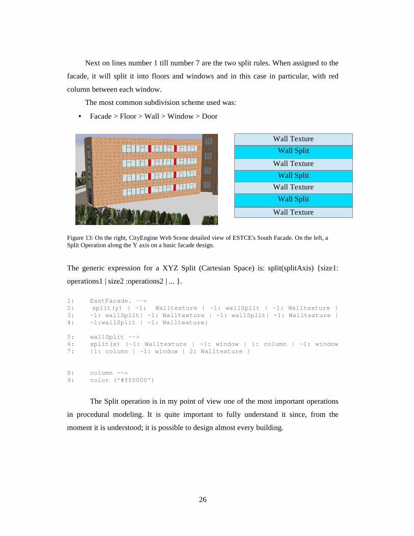
Next on lines number 1 till number 7 are the two split rules. When assigned to the
facade, it will split it into floors and windows and in this case in particular, with red
column between each window.
The most common subdivision scheme used was:
• Facade > Floor > Wall > Window > Door
Figure 13: On the right, CityEngine Web Scene detailed view of ESTCE's South Facade. On the left, a Split Operation along the Y axis on a basic facade design.
The generic expression for a XYZ Split (Cartesian Space) is: split(splitAxis) {size1:
operations1 | size2 :operations2 | ... }.
1: EastFacade. --> 2: split(y) { ~1: Walltexture | ~1: wallSplit | ~1: Walltexture | 3: ~1: wallSplit| ~1: Walltexture | ~1: wallSplit| ~1: Walltexture | 4: ~1:wallSplit | ~1: Walltexture} 5: wallSplit --> 6: split(x) {~1: Walltexture | ~1: window | 1: colu mn | ~1: window 7: |1: column | ~1: window | 2: Walltexture } 8: column --> 9: color ("#ff0000")
The Split operation is in my point of view one of the most important operations
in procedural modeling. It is quite important to fully understand it since, from the
moment it is understood; it is possible to design almost every building.
Wall Texture
Wall Split
Wall Texture
Wall Split
Wall Texture
Wall Split
Wall Texture
27
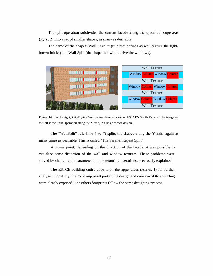
The split operation subdivides the current facade along the specified scope axis
(X, Y, Z) into a set of smaller shapes, as many as desirable.
The name of the shapes: Wall Texture (rule that defines as wall texture the light-
brown bricks) and Wall Split (the shape that will receive the windows).
Figure 14: On the right, CityEngine Web Scene detailed view of ESTCE's South Facade. The image on
the left is the Split Operation along the X axis, in a basic facade design.
The “WallSplit” rule (line 5 to 7) splits the shapes along the Y axis, again as
many times as desirable. This is called “The Parallel Repeat Split”.
At some point, depending on the direction of the facade, it was possible to
visualize some distortion of the wall and window textures. These problems were
solved by changing the parameters on the texturing operations, previously explained.
The ESTCE building entire code is on the appendices (Annex 1) for further
analysis. Hopefully, the most important part of the design and creation of this building
were clearly exposed. The others footprints follow the same designing process.
Wall Texture
Wall Texture
Wall Texture
Wall Texture
Window Column Window Column
Window Column Window Column
Window Column Window Column
28
2.4.2 The Students Residence Building
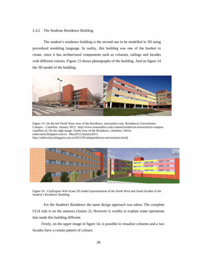
The student’s residence building is the second one to be modelled in 3D using
procedural modeling language. In reality, this building was one of the hardest to
create, since it has architectural components such as columns, railings and facades
with different colours. Figure 13 shows photographs of the building. And on figure 14
the 3D model of the building.
Figure 15: On the left North West view of the Residence. (tuestudios.com. Residencia Universitaria Campus – Castellón. January 2013. http://www.tusestudios.com/content/residencia-universitaria-campus-castellon-2). On the right image: South view of the Residence. (Jiménez, Olivia. oidocozina.blogspot.com.es. May2012.January2013. http://oidocozina.blogspot.com.es/2012/05/independencia-universitaria.html)
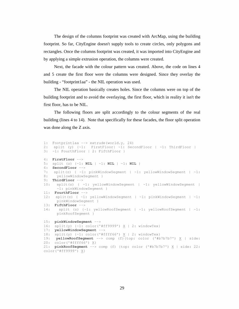
Figure 16 : CityEngine Web Scane 3D model representation of the North West and South facades of the Student’s Residence Building.
For the Student's Residence the same design approach was taken. The complete
CGA rule is on the annexes (Annex 2). However is worthy to explain some operations
that made this building different.
Firstly, on the upper image in figure 14, is possible to visualize columns and a two
facades have a certain pattern of colours.
29
The design of the columns footprint was created with ArcMap, using the building
footprint. So far, CityEngine doesn't supply tools to create circles, only polygons and
rectangles. Once the columns footprint was created, it was imported into CityEngine and
by applying a simple extrusion operation, the columns were created.
Next, the facade with the colour pattern was created. Above, the code on lines 4
and 5 create the first floor were the columns were designed. Since they overlay the
building - “footprint1aa” - the NIL operation was used.
The NIL operation basically creates holes. Since the columns were on top of the
building footprint and to avoid the overlaying, the first floor, which in reality it isn't the
first floor, has to be NIL.
The following floors are split accordingly to the colour segments of the real
building (lines 4 to 14). Note that specifically for these facades, the floor split operation
was done along the Z axis.
1: Footprint1aa --> extrude(world.y, 24) 2: split (y) {~1: FirstFloor| ~1: SecondFloor | ~ 1: ThirdFloor | 3: ~1: FourthFloor | 2: FifthFloor } 4: FirstFloor --> 5: split (z) {~1: NIL | ~1: NIL | ~1: NIL } 6: SecondFloor --> 7: split(z) { ~1: pinkWindowSegment | ~1: yellowWi ndowSegment | ~1: 8: yellowWindowSegment } 9: ThirdFloor --> 10: split(z) { ~1: yellowWindowSegment | ~1: yello wWindowSegment | ~1: pinkWindowSegment } 11: FourthFloor --> 12: split(z) { ~1: yellowWindowSegment | ~1: pinkW indowSegment | ~1: pinkWindowSegment } 13: FifthFloor --> 14: split (z) {~1: yellowRoofSegment | ~1: yellow RoofSegment | ~1: pinkRoofSegment } 15: pinkWindowSegment --> 16: split(y) {~1: color("#ff9999") X | 2: windowTex} 17: yellowWindowSegment --> 18: split(y) {~1: color("#ffff66") X | 2: windowTex} 19: yellowRoofSegment --> comp (f){top: color ("#b7b7b7") X | side: 20: color("#ffff66") X } 21: pinkRoofSegment --> comp (f) {top: color ("#b7b7b7") X | side: 22: color("#ff9999") X }
30
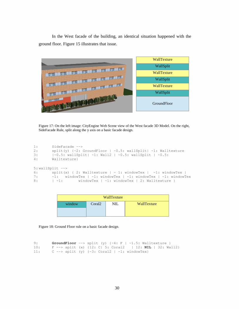
In the West facade of the building, an identical situation happened with the
ground floor. Figure 15 illustrates that issue.
Figure 17: On the left image: CityEngine Web Scene view of the West facade 3D Model. On the right, SideFacade Rule, split along the y axis on a basic facade design.
1: SideFacade --> 2: split(y) {~2: GroundFloor | ~0.5: wallSplit| ~1 : Walltexture 3: |~0.5: wallSplit| ~1: Wall2 | ~0.5: wallSplit | ~0.5: 4: Walltexture} 5: wallSplit --> 6: split(x) { 2: Walltexture | ~ 1: windowTex | ~ 1: windowTex | 7: ~1: windowTex | ~1: windowTex | ~1: windowTex | ~1: windowTex 8: | ~1: windowTex | ~1: windowTex | 2: Walltextu re }
Figure 18: Ground Floor rule on a basic facade design.
9: GroundFloor --> split (y) {~4: F | ~1.5: Walltexture } 10: F --> split (x) {12: C| 5: Coral2 | 12: NIL | 32: Wall2} 11: C --> split (y) {~3: Coral2 | ~1: windowTex}
GroundFloor
WallSplit
WallTexture
WallSplit
WallTexture
WallSplit
WallTexture
WallTexture
Coral2 NIL WallTexture window
31
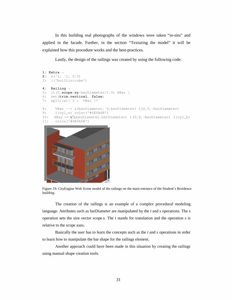
In this building real photographs of the windows were taken “in-situ” and
applied in the facade. Further, in the section “Texturing the model” it will be
explained how this procedure works and the best-practices.
Lastly, the design of the railings was created by using the following code:
1: Extra →
2: s('1, '1, 0.3) 3: i("builtin:cube") 4: Railing → 5: [t(0, scope.sy- barDiameter/1,0) HBar ] 6: set( trim.vertical, false) 7: split(x){ 3 : VBar }* 8: VBar --> s( barDiameter,'0, barDiameter) t(0,0,- barDiameter)
9: i( cyl_v) color("#6E6A6B") 10: HBar --> s('1,barDiameter, barDiameter) t(0,0,- barDiameter) i( cyl_h)
11: color("#6E6A6B")
Figure 19: CityEngine Web Scene model of the railings on the main entrance of the Student’s Residence building.
The creation of the railings is an example of a complex procedural modeling
language. Attributes such as barDiameter are manipulated by the t and s operations. The s
operation sets the size vector scope.s. The t stands for translation and the operation s is
relative to the scope axes.
Basically the user has to learn the concepts such as the t and s operations in order
to learn how to manipulate the bar shape for the railings element.
Another approach could have been made in this situation by creating the railings
using manual shape creation tools.
32
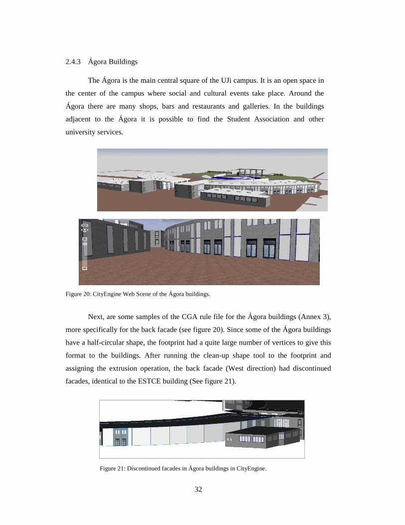
2.4.3 Ágora Buildings
The Ágora is the main central square of the UJi campus. It is an open space in
the center of the campus where social and cultural events take place. Around the
Ágora there are many shops, bars and restaurants and galleries. In the buildings
adjacent to the Ágora it is possible to find the Student Association and other
university services.
Figure 20: CityEngine Web Scene of the Ágora buildings.
Next, are some samples of the CGA rule file for the Ágora buildings (Annex 3),
more specifically for the back facade (see figure 20). Since some of the Ágora buildings
have a half-circular shape, the footprint had a quite large number of vertices to give this
format to the buildings. After running the clean-up shape tool to the footprint and
assigning the extrusion operation, the back facade (West direction) had discontinued
facades, identical to the ESTCE building (See figure 21).
Figure 21: Discontinued facades in Ágora buildings in CityEngine.
33
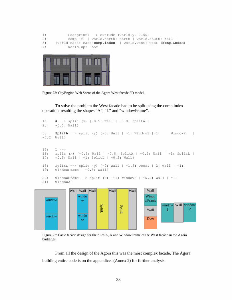
1: Footprint1 --> extrude (world.y, 7.50) 2: comp (f) { world.north: north | world.south: W all | 3: |world.east: east( comp.index) | world.west: west ( comp.index) | 4: world.up: Roof }
Figure 22: CityEngine Web Scene of the Agora West facade 3D model.
To solve the problem the West facade had to be split using the comp index operation, resulting the shapes “A”, “L” and “windowFrame”.
1: A --> split (x) {~0.5: Wall | ~0.8: SplitA | 2: ~0.5: Wall} 3: SplitA --> split (y) {~0: Wall | ~1: Window2 |~1: Window 2 | ~0.2: Wall} 15: L --> 16: split (x) {~0.3: Wall | ~0.8: SplitA | ~0.5: Wa ll | ~1: SplitL | 17: ~0.5: Wall | ~1: SplitL | ~0.2: Wall} 18: SplitL --> split (y) {~0: Wall | ~1.8: Door1 | 2: Wall | ~1: 19: WindowFrame | ~0.5: Wall} 20: WindowFrame --> split (x) {~1: Window2 | ~0.2: Wall | ~1: 21: Window2}
Figure 23: Basic facade design for the rules A, K and WindowFrame of the West facade in the Agora buildings.
From all the design of the Ágora this was the most complex facade. The Ágora
building entire code is on the appendices (Annex 2) for further analysis.
Door
Wall
WindowFrame
Wall
window2
Wall window2
Wall
window
window
Wall
S
plitL
Wall
S
plitL
Wall Wall
window
window
34
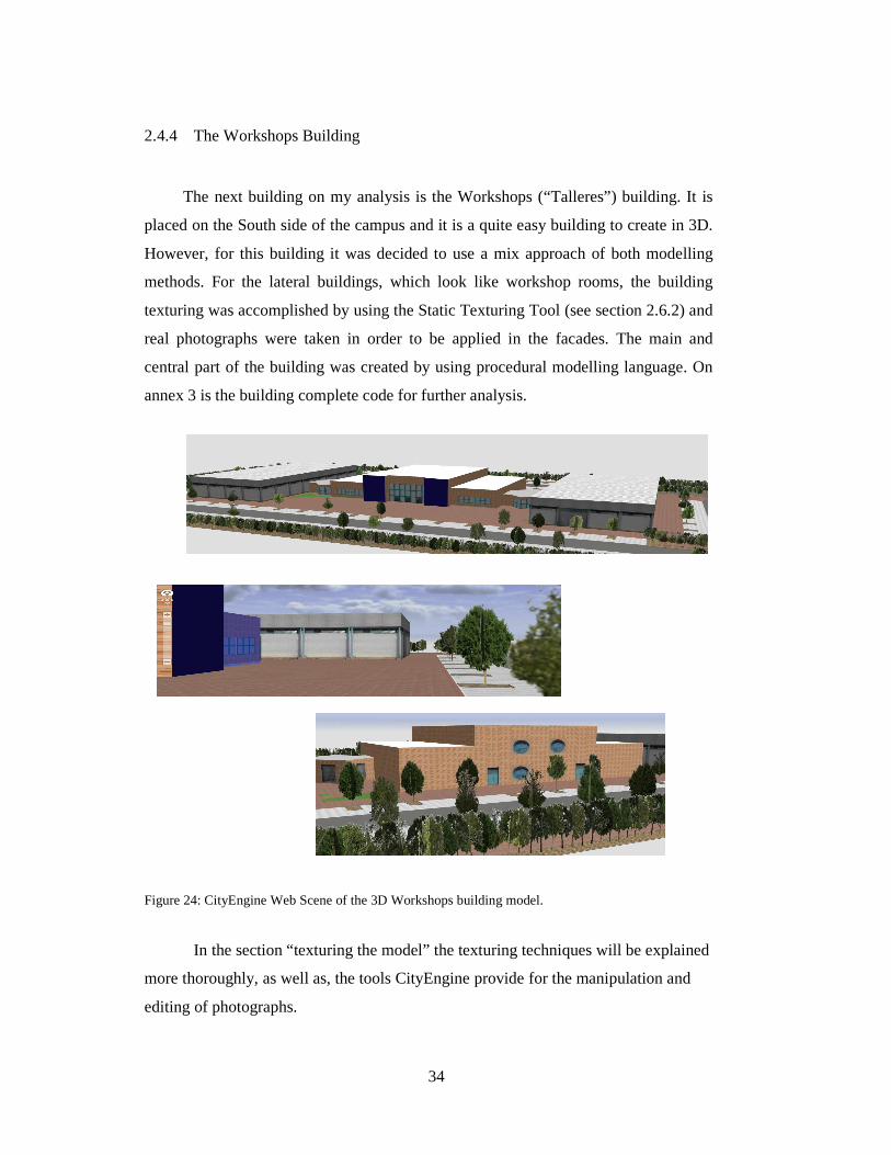
2.4.4 The Workshops Building
The next building on my analysis is the Workshops (“Talleres”) building. It is
placed on the South side of the campus and it is a quite easy building to create in 3D.
However, for this building it was decided to use a mix approach of both modelling
methods. For the lateral buildings, which look like workshop rooms, the building
texturing was accomplished by using the Static Texturing Tool (see section 2.6.2) and
real photographs were taken in order to be applied in the facades. The main and
central part of the building was created by using procedural modelling language. On
annex 3 is the building complete code for further analysis.
Figure 24: CityEngine Web Scene of the 3D Workshops building model.
In the section “texturing the model” the texturing techniques will be explained
more thoroughly, as well as, the tools CityEngine provide for the manipulation and
editing of photographs.
35
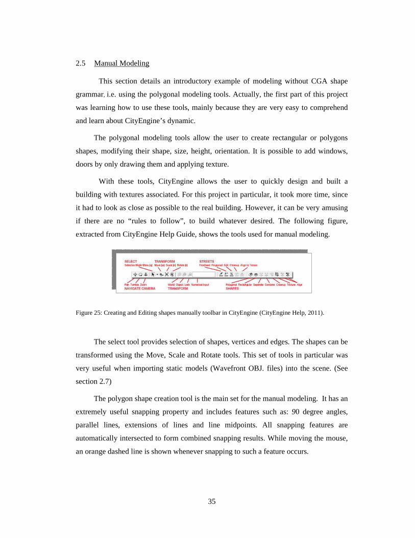
2.5 Manual Modeling
This section details an introductory example of modeling without CGA shape
grammar, i.e. using the polygonal modeling tools. Actually, the first part of this project
was learning how to use these tools, mainly because they are very easy to comprehend
and learn about CityEngine’s dynamic.
The polygonal modeling tools allow the user to create rectangular or polygons
shapes, modifying their shape, size, height, orientation. It is possible to add windows,
doors by only drawing them and applying texture.
With these tools, CityEngine allows the user to quickly design and built a
building with textures associated. For this project in particular, it took more time, since
it had to look as close as possible to the real building. However, it can be very amusing
if there are no “rules to follow”, to build whatever desired. The following figure,
extracted from CityEngine Help Guide, shows the tools used for manual modeling.
Figure 25: Creating and Editing shapes manually toolbar in CityEngine (CityEngine Help, 2011).
The select tool provides selection of shapes, vertices and edges. The shapes can be
transformed using the Move, Scale and Rotate tools. This set of tools in particular was
very useful when importing static models (Wavefront OBJ. files) into the scene. (See
section 2.7)
The polygon shape creation tool is the main set for the manual modeling. It has an
extremely useful snapping property and includes features such as: 90 degree angles,
parallel lines, extensions of lines and line midpoints. All snapping features are
automatically intersected to form combined snapping results. While moving the mouse,
an orange dashed line is shown whenever snapping to such a feature occurs.
36
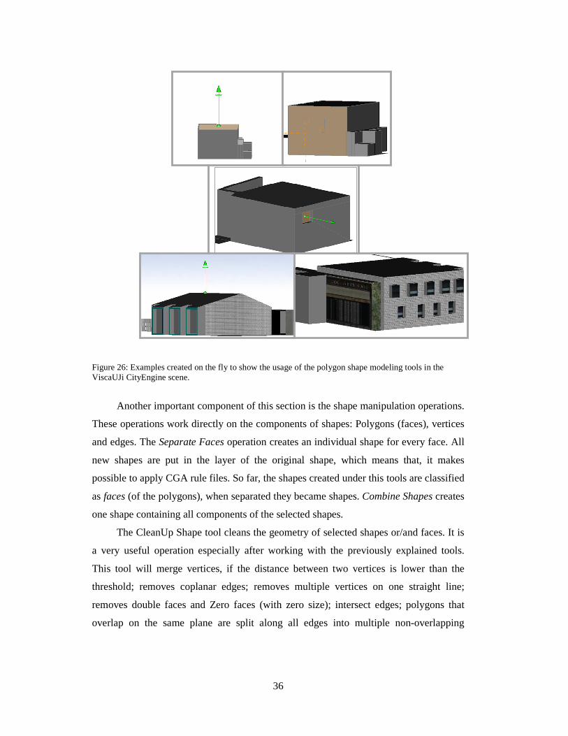
Figure 26: Examples created on the fly to show the usage of the polygon shape modeling tools in the ViscaUJi CityEngine scene.
Another important component of this section is the shape manipulation operations.
These operations work directly on the components of shapes: Polygons (faces), vertices
and edges. The Separate Faces operation creates an individual shape for every face. All
new shapes are put in the layer of the original shape, which means that, it makes
possible to apply CGA rule files. So far, the shapes created under this tools are classified
as faces (of the polygons), when separated they became shapes. Combine Shapes creates
one shape containing all components of the selected shapes.
The CleanUp Shape tool cleans the geometry of selected shapes or/and faces. It is
a very useful operation especially after working with the previously explained tools.
This tool will merge vertices, if the distance between two vertices is lower than the
threshold; removes coplanar edges; removes multiple vertices on one straight line;
removes double faces and Zero faces (with zero size); intersect edges; polygons that
overlap on the same plane are split along all edges into multiple non-overlapping

37
polygons; and it is distance and angle tolerance. It always best to perform a CleanUp
operation before applying textures.
The following section talks about two university buildings created exclusively
with the polygonal modeling tools.
2.5.1 The Sports Building
The University Jaume I offer many sports activities within the campus. Besides
having a sports pavilion, it offers outdoor areas, such as, football fields, tennis courts,
basketball courts, and many more.
Figure 27: The image on the left is the CityEngine Web Scene of the 3D model of the entrance facade of the Sports building. On the right, a photograph from the Sports building. (Arqa.com. Pabellón polideportivo de la Universidad Jaume I de Castellón. November 2004. January 2013. http://arqa.com/arquitectura/internacional/pabellon-polideportivo-de-la-universidad-jaume-i-de-castellon.html)
Figure 28: CityEngine Web Scene 3D Sports Building model.
The creation of the 3D building was exclusively by using the polygonal shape
creation tools and the static texturing tool for applying the textures. The building model is
not entirely accurate to what it looks like in reality. However, for the purpose of
demonstrating the abilities of such tools it is satisfactory and sufficient.
38
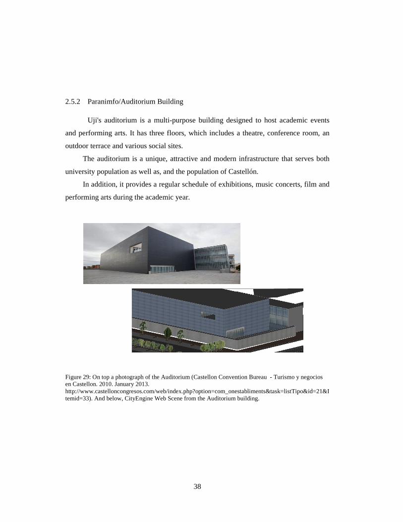
2.5.2 Paranimfo/Auditorium Building
Uji's auditorium is a multi-purpose building designed to host academic events
and performing arts. It has three floors, which includes a theatre, conference room, an
outdoor terrace and various social sites.
The auditorium is a unique, attractive and modern infrastructure that serves both
university population as well as, and the population of Castellón.
In addition, it provides a regular schedule of exhibitions, music concerts, film and
performing arts during the academic year.
Figure 29: On top a photograph of the Auditorium (Castellon Convention Bureau - Turismo y negocios en Castellon. 2010. January 2013. http://www.castelloncongresos.com/web/index.php?option=com_onestabliments&task=listTipo&id=21&Itemid=33). And below, CityEngine Web Scene from the Auditorium building.
39
2.6 Texturing the model
Texturing the buildings is the final part of the 3D model creation and design
process and is considered to be the most important technique in geovisualization in
order to make geographic data visible.
For this project, two types of textures were used: digital textures and
photographs. Digital textures were created previously to this study using Autodesk
3ds Max.
Textures for 3D models depend heavily upon the original photographs from
which they are derived. Such photographs should to be taken in a perspectiveless
manner. Perspectiveless means that the photograph taken has to be fully perpendicular
to the subject. For efficient modeling, textures should be perspectiveless when we
apply them to a model.
During this study, many photographs were taken of the university buildings.
This task it was sometimes difficult to achieve. Most of the building facades were
partially blocked by trees and cars, making harder the task of taking the photographs
as straight as possible. Mid morning sun and shadows were sometimes a problem.
Other inconvenient was the frequent reflection of people and other elements on the
photographs due to reflective glass windows and doors. A high degree of scene detail
and complexity can be achieved through the use of detailed textures on the buildings.
With CityEngine, pictures of actual buildings are projected onto the surfaces of the
building geometry. This method reproduces the most detailed facade.
A high-resolution, photo-realistic 3D environment allows university planners
to see how a proposed building would interact with the existing environment,
ensuring that the size, scale, and style of a proposed building are harmonious with the
existing built environment. (Esri Smart Facilities, 2011)

40
2.6.1 Crop Image Tool
The Crop Image Tool is one of City Engine’s tools was most used throughout
the project. This tool has the wonderful ability to allow to crop the photographs taken,
giving them the right depth and orientation. In earlier versions, the user had to be very
careful how to take the picture of a real facade. For instance, the user had to be aware of
certain rules such us taking it from the ground perspective otherwise the photograph and
thus, the facade would look distorted.
Overall, it is an effective tool for the preparation of facade textures from ground
based facade images; and the perspective correction are done in one step.
Figure 30: CityEngine’s Crop Image tool. On the left side a photograph as input and on the right the result output.
41
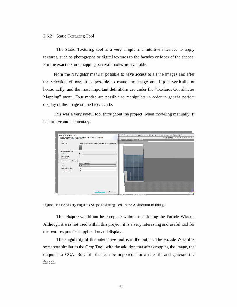
2.6.2 Static Texturing Tool
The Static Texturing tool is a very simple and intuitive interface to apply
textures, such as photographs or digital textures to the facades or faces of the shapes.
For the exact texture mapping, several modes are available.
From the Navigator menu it possible to have access to all the images and after
the selection of one, it is possible to rotate the image and flip it vertically or
horizontally, and the most important definitions are under the “Textures Coordinates
Mapping” menu. Four modes are possible to manipulate in order to get the perfect
display of the image on the face/facade.
This was a very useful tool throughout the project, when modeling manually. It
is intuitive and elementary.
Figure 31: Use of City Engine’s Shape Texturing Tool in the Auditorium Building.
This chapter would not be complete without mentioning the Facade Wizard.
Although it was not used within this project, it is a very interesting and useful tool for
the textures practical application and display.
The singularity of this interactive tool is in the output. The Facade Wizard is
somehow similar to the Crop Tool, with the addition that after cropping the image, the
output is a CGA. Rule file that can be imported into a rule file and generate the
facade.
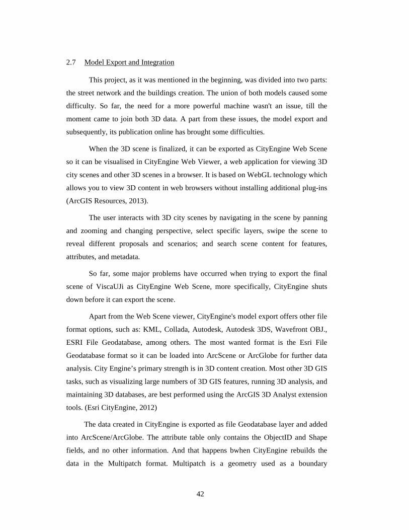
42
2.7 Model Export and Integration
This project, as it was mentioned in the beginning, was divided into two parts:
the street network and the buildings creation. The union of both models caused some
difficulty. So far, the need for a more powerful machine wasn't an issue, till the
moment came to join both 3D data. A part from these issues, the model export and
subsequently, its publication online has brought some difficulties.
When the 3D scene is finalized, it can be exported as CityEngine Web Scene
so it can be visualised in CityEngine Web Viewer, a web application for viewing 3D
city scenes and other 3D scenes in a browser. It is based on WebGL technology which
allows you to view 3D content in web browsers without installing additional plug-ins
(ArcGIS Resources, 2013).
The user interacts with 3D city scenes by navigating in the scene by panning
and zooming and changing perspective, select specific layers, swipe the scene to
reveal different proposals and scenarios; and search scene content for features,
attributes, and metadata.
So far, some major problems have occurred when trying to export the final
scene of ViscaUJi as CityEngine Web Scene, more specifically, CityEngine shuts
down before it can export the scene.
Apart from the Web Scene viewer, CityEngine's model export offers other file
format options, such as: KML, Collada, Autodesk, Autodesk 3DS, Wavefront OBJ.,
ESRI File Geodatabase, among others. The most wanted format is the Esri File
Geodatabase format so it can be loaded into ArcScene or ArcGlobe for further data
analysis. City Engine’s primary strength is in 3D content creation. Most other 3D GIS
tasks, such as visualizing large numbers of 3D GIS features, running 3D analysis, and
maintaining 3D databases, are best performed using the ArcGIS 3D Analyst extension
tools. (Esri CityEngine, 2012)
The data created in CityEngine is exported as file Geodatabase layer and added
into ArcScene/ArcGlobe. The attribute table only contains the ObjectID and Shape
fields, and no other information. And that happens bwhen CityEngine rebuilds the
data in the Multipatch format. Multipatch is a geometry used as a boundary
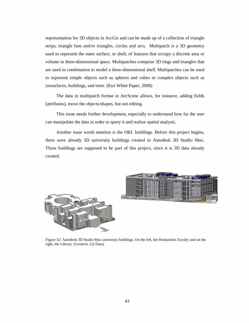
43
representation for 3D objects in ArcGis and can be made up of a collection of triangle
strips, triangle fans and/or triangles, circles and arcs. Multipatch is a 3D geometry
used to represent the outer surface, or shell, of features that occupy a discrete area or
volume in three-dimensional space. Multipatches comprise 3D rings and triangles that
are used in combination to model a three-dimensional shell. Multipatches can be used
to represent simple objects such as spheres and cubes or complex objects such as
isosurfaces, buildings, and trees. (Esri White Paper, 2008)
The data in multipatch format in ArcScene allows, for instance, adding fields
(attributes), move the objects/shapes, but not editing.
This issue needs further development, especially to understand how far the user
can manipulate the data in order to query it and realize spatial analysis.
Another issue worth mention is the OBJ. buildings. Before this project begins,
there were already 3D university buildings created in Autodesk 3D Studio Max.
These buildings are supposed to be part of this project, since it is 3D data already
created.
Figure 32: Autodesk 3D Studio Max university buildings. On the left, the Humanities Faculty and on the right, the Library. (Geotech, Uji Data)
44
Figure 33: Autodesk 3D Studio Max university buildings: on the left image the Technology & Experimental Sciences building and on the right the Economics Faculty. (Geotech, Uji Data)
The only possible file format that when imported into CitEngine had “less”
errors was Wavefront OBJ. Still, it presented major errors, for instance, missing
walls, overlaying walls with windows, and so forth.
The buildings on the figure 33 are the perfect example of the problems mentioned
above. To sum up, these buildings need a serious cleaning process and hopefully they
will be fit to integrate the final model.
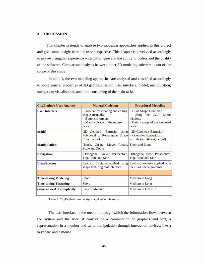
45
3 DISCUSSION
This chapter pretends to analyse two modeling approaches applied in this project
and give some insight from the user perspective. This chapter is developed accordingly
to my own singular experience with CityEngine and the ability to understand the quality
of the software. Comparison analysis between other 3D modeling software is out of the
scope of this study.
In table 1, the two modeling approaches are analysed and classified accordingly
to some general properties of 3D geovisualisation: user interface; model; manipulation;
navigation; visualisation; and time-consuming of the main tasks.
CityEngine's User Analysis Manual Modeling Procedural Modeling
User Interface - Toolbar for creating and editing shapes manually; - Buttons shortcuts; - Mainly Usage of the mouse device.
- CGA Shape Grammar; - Using the CGA Editor window; - Mainly usage of the keyboard device.
Model 2D Geometry Extrusion using Polygonal or Rectangular Shape Creation tool
- 2D Geometry Extrusion - Operation Extrusion: extrude (axisWorld, height)
Manipulation Track, Create, Move, Rotate, Scale and Zoom
Track and Zoom
Navigation Orthogonal view, Perspective, Top, Front and Side
Orthogonal view, Perspective, Top, Front and Side
Visualization Realistic Textures applied using shape texturing tool interface
Realistic textures applied with the CGA shape grammar
Time-taking Modeling Short Medium to Long
Time-taking Texturing Short Medium to Long
General level of complexity Easy to Medium Medium to Difficult
Table 1: CityEngine's user analysis applied to this study.
The user interface is the medium through which the information flows between
the system and the user; it consists of a combination of graphics and text, a
representation in a monitor and same manipulation through interaction devices, like a
keyboard and a mouse.

46
Interaction is a somewhat generic term comprising the process of a human
communicating with the computer. Interaction and navigation are thus not exactly
separable but for the following considerations interaction is defined to be the process of
interaction with the data and display aiming at gaining insight.
Navigation is an important part of 3D geovisualization as it allows the user to
overcome occlusion (e.g. making hidden objects visible through a change of the
viewpoint) or to look at the information from a different angle (a form of re-expression)
(Nielsen, 2007).
Firstly, regarding the use of procedural modeling language, it revealed to be
somehow easy to pick-up and efficient. All the 3D design and modeling is made through
the CGA shape grammar and using the CGA editor view in the program.
The main advantage over the manual modeling is the flexibility that gives to the
user. When creating a 3D model of a building, a street and/or street furniture, the user
can always go back and modify parameters in the rules. Likewise, the same CGA rule
can be assigned to many buildings, if in reality they have the same architectural style,
for instance, some CityEngine examples for the cities of Paris or New York.
Perhaps for a user with few programming skills it can be a bit alarming. Definitely
it can take a certain amount of time to understand how Computer Generated
Architecture works and the shape grammar. However, CityEngine can be considered as
user-friendly software, and when the user acquire the knowledge of procedural
language, there are many things to create and design. It is a new world! And the best of
it is that it is in 3D!
Finally, regarding the manual modelling, this method uses polygon shape
creation/editing tools and it’s known to be more intuitive and faster to comprehend.
Indeed, this method can be somewhat similar to other manual procedures used in other
3D softwares such as Google SketchUp.
The manual modeling main characteristic is the intuitive and simple set of tools
that the user can and should use. It's less time-consuming, the opposite of the other
method, it is faster and can generate beautiful 3D buildings, but not in a mass-
production way. So it is less time-consuming if the user is working on minor dimension
objects or working with details. To produce entire 3D urban cities manual modeling is
definitely out of question.
47
While working with the CityEngine's set of manual tools, in particular the main
disadvantages are: 1) there isn't a measuring tool, the only notion a user might have
while drawing a building is when using the polygon shape creation it has a counter that
is measuring while you are drawing; 2) there is no circle or arc creation tool, when
designing urban landscapes elements such as columns are important.
In general, the main advantage of the manual modeling approach is the fact that
isn't dynamic, as the procedural modeling language. For instance, after a 3D building is
finalized, the user needs to change the measures of the windows, with CGA shape
grammars that can easily be modified in the rule file and press to generate again. If
using manual tools the user will need to draw again the object.
In summary both methods have their strengths and weaknesses. Nevertheless,
procedural modeling language is the best within CityEngine environment to model 3D
models. In the majority of the cases, the optimal approach is to mix both methods, for
instance finishing details in a building using manual tools (in case the shape grammars
become too complex or impossible to reproduce such detail).
4 CONCLUSION
The University Jaume I have made a major investment with the project Smart
Campus. ViscaUJi not only models the existing built environment but also looks into the
future; it has allowed the university to centralize campus maps, plans, and planning
content. Further, it has improved data access for future development planning and
review. Using Esri products such as City Engine as the foundation for a 3D campus
designing helps a pioneer the usage of 3D GIS-based solutions.
The project outlined here and the resulting 3D university buildings will hopefully
be used as a resource for 3D visualizations and navigation, as well as, a source of data –
3D data. 3D visualization and navigation of 3D maps provide a powerful way to explore
the campus information by visualizing the data through different points of view.
From 2008 till nowadays, CityEngine has been growing and developing into 3D
GIS program. Nonetheless, CityEngine still has a long way to go.
48
So, where does CityEngine stands in GIS world? Undoubtedly CityEngine’s
main power is to rapidly build accurate and visually compelling city models. However,
that doesn’t make CityEngine GIS software, but an average 3D model creator/designer.
What makes CityEngine “GIS efficient” is allowing a GIS user to use its own GIS data.
The software allows to import and export attributed GIS data such as streets
network, buildings footprints, or 3D buildings using the Esri file geodatabase or
shapefile format. However, to perform further spatial analysis after working in
CityEngine the user will have to export it and add into ArcGis 3D analyst set of tools.
Regarding the practical experience of this study, working with CityEngine was
quite an exceptional and new experience. From the point of view of a Geographer,
understanding and working with procedural modeling language was very challenging.
In the beginning the learning process was somehow slow, but in the end, the
difficulties were overcame and now consider myself a competent user of CityEngine.
In conclusion, CityEngine is amazing 3D modelling software for geographers and
professionals who work daily in Urban Planning departments and need sophisticated and
reliable software to help planning and managing a city. Using software like CityEngine
in Smart Cities or Smart Campus projects is a step forward into progress and
development of the today’s urban reality.
4.1 Future Work
Further work on this topic should focus on the following:
• Integration with other Smart Campus projects. Usage and linkage of the 3D data
created in this project with the applications developed or to be developed in the
future.
• Finish the designing and creation of the remaining university buildings.
• Indoor Mapping using the available CAD files for the buildings at Uji.
Architectural drawings are essential to designing, narrating, and executing a
construction project. Most drawings take the form of floor plans, which portray
an orthographic top-down projection of each building level. Floor plans have
various levels of detail, including the rooms, hallways, stairs and architectural
49
components. CAD files manage to cover the building’s complete layout, which
is sufficient to build a model for most applications. (Yin & Wonka & Razdan,
2013)
• Creating a Query tool with 3D visualization: 3D city information modeling
exploration through 3D navigating and querying is particularly crucial since its
purpose is to extract the relevant information in the available data. (Fredericque
& Lapierr, 2010)
• In the end, while researching for the theoretical framework of this study, a
considerable amount of literature was found regarding the topic 3D
Geovisualisation. More specifically, a framework for evaluating the usefulness
and appropriateness of 3D geovisualization. It would be very interesting to make
a deeper and qualitative analysis of the work produced within this study to assess
the data quality produced. The analysis would take into account, for instance, the
concepts of evaluating usability and usefulness. Furthermore, a review of
different parameters to help the purpose-based definition of tasks for the
evaluation of usefulness. Generally, it would be interesting to look at non-
technical aspects of this study.
50
BIBLIOGRAPHIC REFERENCES
BACH, B., WILHELMER, D., PALENSKY, P. Smart buildings, smart cities and governing innovation in the new millennium. (Online) URL: http://www.researchgate.net/publication/224167657_Smart_buildings_smart_cities_and_governing_innovation_in_the_new_millennium (Access: Ocotober 2012)
BAO, F., SCHWARZ, M., WONKA, P. 2013. Procedural Facade Variations from a
Single Layout. (Online) URL: http://peterwonka.net/Publications/2012.TOG.Bao.FacadeVariations.pdf. (Access: January 2013)
CARAGLIU, A., DEL BO, C., NIJKAMP., P. Smart Cities in Europe. 3rd Central
European Conference in Regional Science – CERS, 2009. (Online) URL: http://www.cers.tuke.sk/cers2009/PDF/01_03_Nijkamp.pdf (Access: October 2012)
CHOURABI, H., GIL-GARCIA, J.R., PARDO, T.A., NAM, T., MELLOULI, S., Jochen Scholl, H., Walker, S., Nahon, K. Understanding Smart Cities: An Integrative Framework. 2012 45th Hawaii International Conference on System Sciences (Online) URL: http://www.ctg.albany.edu/publications/journals/hicss_2012_smartcities/hicss_2012_smartcities.pdf (Access: October 2012)
ELWANNAS, R. 3D GIS: It's a Brave new World. FIG Working Week 2011. Bridging the Gap between Cultures. Marrakech, Morocco, 18-22 May 2011. (Online) URL: http://www.gdmc.nl/3dcadastres/literature/3Dcad_2011_04.pdf (Access: January 2013)
ESRI. Smart Facilities.2011. 3D Edition (Online) URL: http://www.esri.com/library/newsletters/smart_facilities/smart-facilities-spring11.pdf (Access: October 2012)
ESRI White Paper. The Multipatch Geometry Type. December 2008. (Online) URL: http://www.esri.com/library/whitepapers/pdfs/multipatch-geometry-type.pdf (Access: February 2013)
FREDERICQUE, B., LAPIERR, A. 3D City GIS – A Major Step Towards Sustainable Infrastructure. 2010 (Online) URL: http://www.fig.net/pub/fig2010/papers/ts08b%5Cts08b_fredericque_lapierre_4703.pdf (Access September 2012)
51
FREDERICQUE, B., LAPIERR, A. The Benefits of a 3D City GIS for Sustaining City Infrastructure. (Online) URL: http://ftp2.bentley.com/dist/collateral/docs/press/the-benefits-of-a-3d-city-gis-for-sustaining-city-infrastructure_archtecture-update.pdf (Access: September 2012)
HARRISON, C., ABBOTT, DONNELLY, I. A. Theory of Smart Cities (Online)URL: http://journals.isss.org/index.php/proceedings55th/article/view/1703 (Access: September 2012)
LIPP, M., WONKA, P., WIMMER, M. 2008. Interactive Visual Editing of Grammars for Procedural Architecture. (Online) URL: http://peterwonka.net/Publications/2008.SG.Lipp.Interactive%20Visua%20Editing.pdf (Access: January 2013).
LAITON, A. Esri buys Procedural City Engine. (Online)
http://andrewlainton.wordpress.com/2011/07/20/esri-buys-procedural-city-engine/ Access: December 2012
MATHIAS, M., MARTINOVIC, A., WEISSENBERGY, J., VAN GOOL, L. 2011. Procedural 3D Building Reconstruction using Shape Grammars and Detectors. Computer Vision Laboratory. Zürich, Switzerland. (Online) URL: http://www.vision.ee.ethz.ch/publications/papers/proceedings/eth_biwi_00875.pdf. (Access: January 2013)
MULLER, P., PARISH, Y I H. Procedural Modeling for Cities. 2001. (Online) URL: http://graphics.ethz.ch/Downloads/Publications/Papers/2001/p_Par01.pdf (Access: October 2012)
MULLER, P., PARISH, HAEGLER, S., ULMER, A., VAN GOOL, L. Procedural Modeling of Buildings. 2006. (Online) URL: http://peterwonka.net./Publications/mueller.procedural%20modeling%20of%20buildings.SG2006.final-web.pdf (Access: January 2013)
NAGARAJAN, S., SUDALAIMUTHU, K. Web 3DS Business Models. 2012. (Online) URL: http://www.gisdevelopment.net/application/urban/overview/urbano047pf.htm (Access: September 2012)
52
NIELSEN, A., 2007. A Qualification of 3D Geovisualisation.PhD. Aalborg University. (Online) URL: http://vbn.aau.dk/ws/files/16918248/phdafhandling_Anette_20Nielsen.pdf. (Access: January 2013)
ROCHE, S., NABIAN, N., KLOECKL, K., and RATTI, C. Are ‘Smart Cities’ Smart Enough? (Online) URL: http://www.gsdi.org/gsdiconf/gsdi13/papers/182.pdf (Access: September 2012)
SANCHIS, A., ARNAL, A., MOLINA, W., SANCHIS, V., DÍAZ, L., HUERTA, J., GOULD, M. smartUJI: campus inteligente como IDE local. III Jornadas Ibéricas de las Infraestructuras de Datos Espaciales (JIIDE 2012). Madrid, October 2012. (Online) URL: http://www.ign.es/resources/jiide2012/jueves/tarde/Ecuador/6.viscaUJI.pdf (Access: January 2012)
SAMAD, A., HUSSEIN, S, M., KARNADI, M, S., BOHARI, S.N., SULDI, A, M., MAAROF, I. Web GIS Solution and 3D Visualization towards Sustainability of Georgetown as World Heritage Site. 2012 IEEE 8th International Colloquium on Signal Processing and its Applications. (Online) URL: www.asprg.net/cspa2012 (Access: October 2012)
SENGUPTA, S. 2011. GIS-based Smart Campus System using 3D Modeling (Online) URL: http://www.geospatialworldforum.org/2011/proceeding/pdf/Smita%20Sengupta.pdf (Access: October 2012)
Smart Cities Project. Creating Smarter Cities - Lessons from the Smart Cities Projects. 2011. (Online) URL: http://www.epractice.eu/en/library/5390006 (Access: October 2012)
STINY, G., GIPS, J. 1972. Shape Grammars and the Generative Specification of Painting ans Sculpture. (Online) URL: http://shapegrammar.org/ifip/ifip1.html (Access: January 2013)
STOTER, J., ZLATANOVA, S. 2003. 3D GIS, where are we standing? Section GIS technology, Delft University of Technology, The Netherlands. (Online) URL: http://libra.msra.cn/Publication/11431320/3d-gis-where-are-we-standing (Access: Januray 2013)
53
VAN MAREN, G., SHEPHARD, N., SCHUBIGER, S. 2012. Developing with Esri CityEngine (Online) URL: http://proceedings.esri.com/library/userconf/devsummit12/papers/developing_with_esri_cityengine.pdf (Access: October 2012)
WATSON, B., MULLER, P., WONKA, P., SEXTON, C., VERYOVKA, O., FULLER, F. 2008. Procedural Urban Modeling in Practice (Online) URL: http://peterwonka.net/Publications/2008.CG&A.Watson.Procedural%20Modeling%20Tutorial.pdf. Access: January 2013
WONKA, P., WIMMER, M., SILLION, F., RIBARSKY, W. 2003. “Instant Architecture”. (Online) URL: http://www.cg.tuwien.ac.at/research/vr/instantarchitecture/instant_architecture.pdf. (Access: January 2013)
YIN, X., WONKA, P., RAZDAN, A. Generating 3D Building Models from Architectural Drawings: a survey 2009 (Online) URL: http://peterwonka.net/Publications/2009.CGA.Yin.FloorplanExtrusionSurvey.IEEEDigitalLibrary.pdf. (Access: January 2013)
ZHOU L., SUN Jia-long, WEI-XIAO, Li., HE, B., WEI-WEI, C. The Study on the technique of the 3D GIS modeling based on the digital photogrammetry. (Online) URL: http://www.isprs.org/proceedings/XXXVII/congress/3b_pdf/118.pdf (Access: October 2012)
ArcGIS Resources, < http://resources.arcgis.com> (Visited: January 2013)
CityEngine Offical Documentation: CityEngine Help Guide, CityEngine Tutorials and Examples.
GEOTEC: Geospatial Technologies Research Group, http://www.geotec.uji.es
(Visited: December 2012 and January 2013)
H. KOLBE, T. CityGML Project, < http://www.citygml.org>, (Visited: January
2013)
University Jaume I, Castelló, < www.uji.es>, (Visited: January 2013)
YouTube, CityEngineTV, <http://www.youtube.com/user/cityenginetv> (Visited:
September/October 2012)
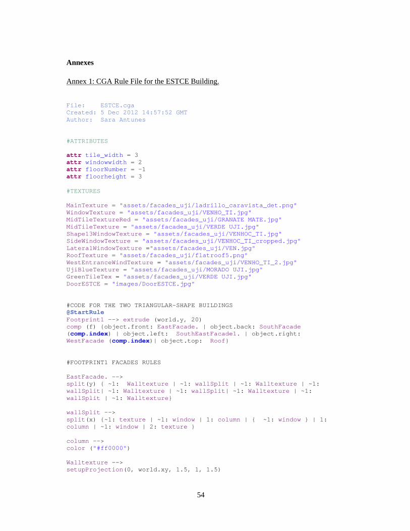
54
Annexes
Annex 1: CGA Rule File for the ESTCE Building.
File: ESTCE.cga Created: 5 Dec 2012 14:57:52 GMT Author: Sara Antunes #ATTRIBUTES attr tile_width = 3 attr windowwidth = 2 attr floorNumber = -1 attr floorheight = 3 #TEXTURES MainTexture = "assets/facades_uji/ladrillo_caravista_det.png" WindowTexture = "assets/facades_uji/VENHO_TI.jpg" MidTileTextureRed = "assets/facades_uji/GRANATE MATE.jpg" MidTileTexture = "assets/facades_uji/VERDE UJI.jpg" Shape13WindowTexture = "assets/facades_uji/VENHOC_TI.jpg" SideWindowTexture = "assets/facades_uji/VENHOC_TI_cropped.jpg" LateralWindowTexture = "assets/facades_uji/VEN.jpg" RoofTexture = "assets/facades_uji/flatroof5.png" WestEntranceWindTexture = "assets/facades_uji/VENHO_TI_2.jpg" UjiBlueTexture = "assets/facades_uji/MORADO UJI.jpg" GreenTileTex = "assets/facades_uji/VERDE UJI.jpg" DoorESTCE = "images/DoorESTCE.jpg" #CODE FOR THE TWO TRIANGULAR-SHAPE BUILDINGS @StartRule Footprint1 --> extrude (world.y, 20) comp (f) {object.front: EastFacade. | object.back: SouthFacade ( comp.index) | object.left: SouthEastFacade1. | object.right: WestFacade ( comp.index)| object.top: Roof } #FOOTPRINT1 FACADES RULES EastFacade. --> split (y) { ~1: Walltexture | ~1: wallSplit | ~1: Walltexture | ~1: wallSplit | ~1: Walltexture | ~1: wallSplit | ~1: Walltexture | ~1: wallSplit | ~1: Walltexture } wallSplit --> split (x) {~1: texture | ~1: window | 1: column | { ~1: window } | 1: column | ~1: window | 2: texture } column --> color ( "#ff0000" ) Walltexture --> setupProjection (0, world.xy, 1.5, 1, 1.5)
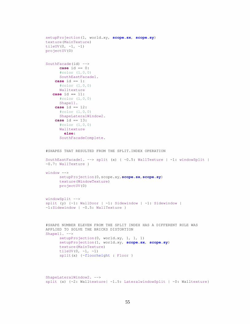
55
setupProjection (1, world.xy, scope.sx, scope.sy) texture ( MainTexture ) tileUV (0, ~1, ~1) projectUV (0) SouthFacade (id) --> case id == 0: #color (1,0,0) SouthEastFacade1. case id == 1: #color (1,0,0) Walltexture case id == 11: #color (1,0,0) Shape11. case id == 12: #color (1,0,0) ShapeLateralWindow2. case id == 13: #color (1,0,0) Walltexture else: SouthFacadeComplete. #SHAPES THAT RESULTED FROM THE SPLIT.INDEX OPERATIO N SouthEastFacade1. --> split (x) { ~0.5: WallTexture | ~1: windowSplit | ~0.7: WallTexture } window --> setupProjection (0,scope.xy, scope.sx, scope.sy) texture ( WindowTexture ) projectUV (0) windowSplit --> split (y) {~1: WallDoor | ~1: Sidewindow | ~1: Sidewindow | ~1: Sidewindow | ~0.5: WallTexture } #SHAPE NUMBER ELEVEN FROM THE SPLIT INDEX HAS A DIF FERENT RULE WAS APPLIED TO SOLVE THE BRICKS DISTORTION Shape11. --> setupProjection (0, world.xy, 1, 1, 1) setupProjection (1, world.xy, scope.sx, scope.sy) texture ( MainTexture ) tileUV (0, ~1, ~1) split (x) {~ floorheight : Floor } ShapeLateralWindow2. --> split (x) {~2: Wall texture | ~1.5: LateralwindowSplit | ~0: Wall texture }

56
LateralwindowSplit --> split (y) { ~1: Lateralwindow | ~1: Lateralwindow | ~1: Lateralwindow | ~1: Lateralwindow | ~1: Lateralwindow | ~0.5: Wall texture } SouthFacadeComplete. --> split (x) {~ floorheight: Floor } Floor --> split (y) {~1.5: Wall texture | {~5: Tile }* | ~1: Wall texture } Tile --> split (y) {0.5: Wall texture | ~1: window | 0.5: Wall texture } #LAST FACADE RULE WestFacade (id) --> case id == 0 : #color (1,0,1) EastFacadeInverse. case id == 1 : #color (1,0,1) ShapeLateralWindow1. else : #color (1,0,1) ShapeLateralWindow1. EastFacadeInverse. --> split (y) { ~1: texture | ~1: wallSplitInverse | ~1: texture | ~1: wallSplitInverse | ~1: texture | ~1: wallSplitInverse | ~1: texture | ~1: wallSplitInverse | ~1: texture } wallSplitInverse --> split (x) {~0.2: Wall texture | ~1: window | 1: columnYellow | { ~1: window } | 1: columnYellow | ~1: window | 10: Wall texture } columnYellow --> color ( "#ffb000" ) ShapeLateralWindow1. --> split (x) { ~0.5: Wall texture | ~1.5: LateralwindowSplit | ~2: Wall texture } #ROOF RULE COMMON FOR ALL THE FACADES Roof --> setupProjection (1, world.xy, scope.sx, scope.sy) texture ( RoofTexture ) tileUV (1, ~1, ~1) projectUV (0) #SECOND RULE FOR THE TRIANGULAR-SHAPE BUILDING Footprint2 --> extrude (world.y, 20) comp (f) {object.front: NorthEastFacade ( comp.index)| object.back: EastFacadeInverse. | object.left: NorthEastFacadeb ( comp.index) | object.right: EastFacade. | object.top: Roof }
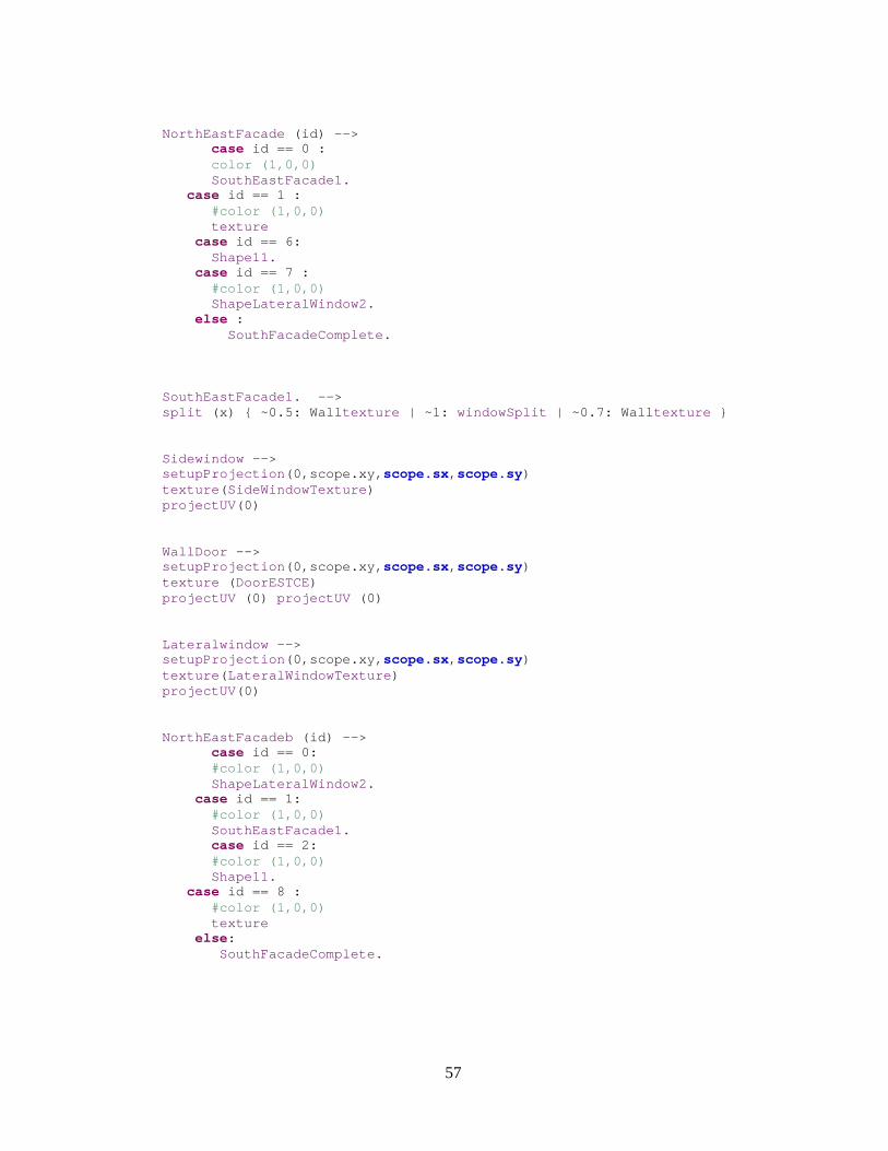
57
NorthEastFacade (id) --> case id == 0 : color (1,0,0) SouthEastFacade1. case id == 1 : #color (1,0,0) texture case id == 6: Shape11. case id == 7 : #color (1,0,0) ShapeLateralWindow2. else : SouthFacadeComplete. SouthEastFacade1. --> split (x) { ~0.5: Wall texture | ~1: windowSplit | ~0.7: Wall texture } Sidewindow --> setupProjection (0,scope.xy, scope.sx, scope.sy) texture ( SideWindowTexture ) projectUV (0) WallDoor --> setupProjection (0,scope.xy, scope.sx, scope.sy) texture ( DoorESTCE) projectUV (0) projectUV (0) Lateralwindow --> setupProjection (0,scope.xy, scope.sx, scope.sy) texture ( LateralWindowTexture ) projectUV (0) NorthEastFacadeb (id) --> case id == 0: #color (1,0,0) ShapeLateralWindow2. case id == 1: #color (1,0,0) SouthEastFacade1. case id == 2: #color (1,0,0) Shape11. case id == 8 : #color (1,0,0) texture else: SouthFacadeComplete.
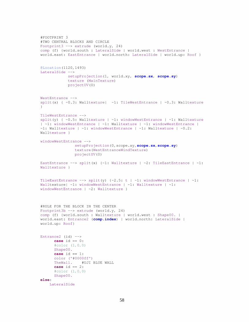
58
#FOOTPRINT 3 #TWO CENTRAL BLOCKS AND CIRCLE Footprint3 --> extrude (world.y, 24) comp (f) {world.south : LateralSide | world.west : WestEntrance | world.east: EastEntrance | world.north: LateralSide | world.up: Roof } @Location (1120,1493) LateralSide --> setupProjection (1, world.xy, scope.sx, scope.sy) texture ( MainTexture ) projectUV (0) WestEntrance --> split (x) { ~0.3: Wall texture | ~1: TileWestEntrance | ~0.3: Wall texture } TileWestEntrance --> split (y) { ~0.5: Wall texture | ~1: windowWestEntrance | ~1: Wall texture | ~1: windowWestEntrance | ~1: Wall texture | ~1: windowWestEntrance | ~1: Wall texture | ~1: windowWestEntrance | ~1: Wall texture | ~0.2: Wall texture } windowWestEntrance --> setupProjection (0,scope.xy, scope.sx, scope.sy) texture ( WestEntranceWindTexture ) projectUV (0) EastEntrance --> split (x) {~1: Walltexture | ~2: TileEastEntrance | ~1: Walltexture } TileEastEntrance --> split (y) {~2.5: t | ~1: windowWestEntrance | ~1: Wall texture| ~1: windowWestEntrance | ~1: Walltexture | ~1: windowWestEntrance | ~2: Walltexture } #RULE FOR THE BLOCK IN THE CENTER Footprint3b --> extrude (world.y, 24) comp (f) {world.south : Wall texture | world.west : Shape00. | world.east: Entrance2 ( comp.index) | world.north: LateralSide | world.up: Roof } Entrance2 (id) --> case id == 0: #color (1,0,0) Shape00. case id == 1: color ("#0000ff") TheWall. #UJI BLUE WALL case id == 2: #color (1,0,0) Shape00. else: LateralSide
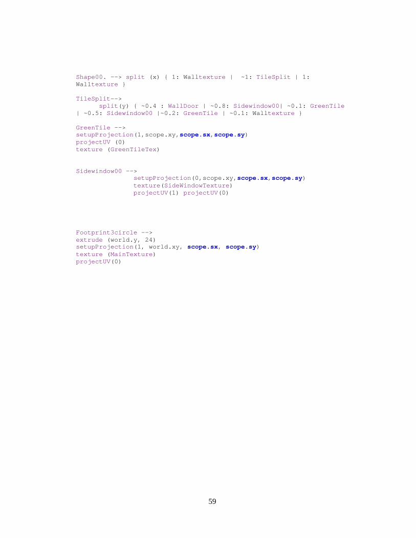
59
Shape00. --> split (x) { 1: Wall texture | ~1: TileSplit | 1: Wall texture } TileSplit --> split (y) { ~0.4 : WallDoor | ~0.8: Sidewindow00 | ~0.1: GreenTile | ~0.5: Sidewindow00 |~0.2: GreenTile | ~0.1: Wall texture } GreenTile --> setupProjection (1,scope.xy, scope.sx, scope.sy) projectUV (0) texture ( GreenTileTex ) Sidewindow00 --> setupProjection (0,scope.xy, scope.sx, scope.sy) texture ( SideWindowTexture ) projectUV (1) projectUV (0) Footprint3circle --> extrude (world.y, 24) setupProjection (1, world.xy, scope.sx, scope.sy) texture ( MainTexture ) projectUV (0)
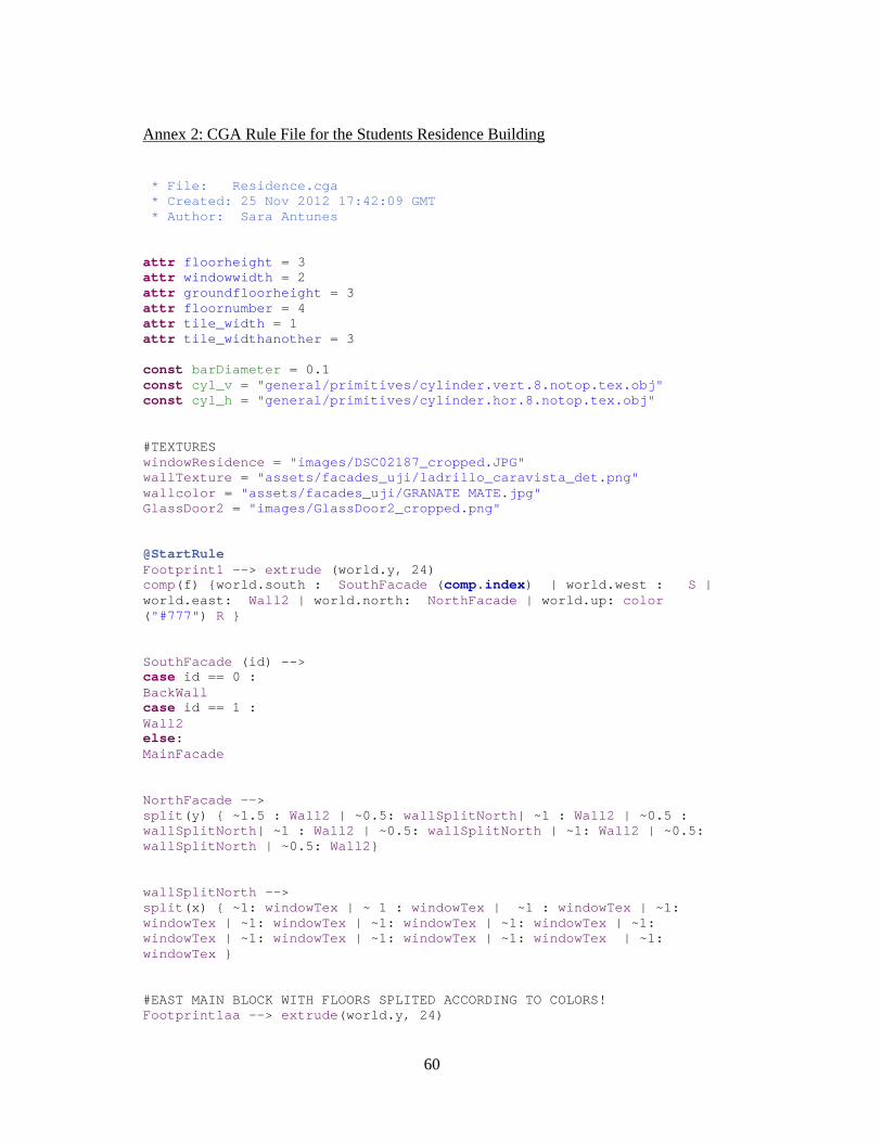
60
Annex 2: CGA Rule File for the Students Residence Building
* File: Residence.cga * Created: 25 Nov 2012 17:42:09 GMT * Author: Sara Antunes attr floorheight = 3 attr windowwidth = 2 attr groundfloorheight = 3 attr floornumber = 4 attr tile_width = 1 attr tile_widthanother = 3 const barDiameter = 0.1 const cyl_v = "general/primitives/cylinder.vert.8.notop.tex.obj" const cyl_h = "general/primitives/cylinder.hor.8.notop.tex.obj" #TEXTURES windowResidence = "images/DSC02187_cropped.JPG" wallTexture = "assets/facades_uji/ladrillo_caravista_det.png" wallcolor = "assets/facades_uji/GRANATE MATE.jpg" GlassDoor2 = "images/GlassDoor2_cropped.png" @StartRule Footprint1 --> extrude (world.y, 24) comp(f) {world.south : SouthFacade ( comp.index) | world.west : S | world.east: Wall2 | world.north: NorthFacade | world.up: color ( "#777" ) R } SouthFacade (id) --> case id == 0 : BackWall case id == 1 : Wall2 else: MainFacade NorthFacade --> split (y) { ~1.5 : Wall2 | ~0.5: wallSplitNorth | ~1 : Wall2 | ~0.5 : wallSplitNorth | ~1 : Wall2 | ~0.5: wallSplitNorth | ~1: Wall2 | ~0.5: wallSplitNorth | ~0.5: Wall2 } wallSplitNorth --> split (x) { ~1: windowTex | ~ 1 : windowTex | ~1 : windowTex | ~1: windowTex | ~1: windowTex | ~1: windowTex | ~1: windowTex | ~1: windowTex | ~1: windowTex | ~1: windowTex | ~1: windowTex | ~1: windowTex } #EAST MAIN BLOCK WITH FLOORS SPLITED ACCORDING TO C OLORS! Footprint1aa --> extrude (world.y, 24)
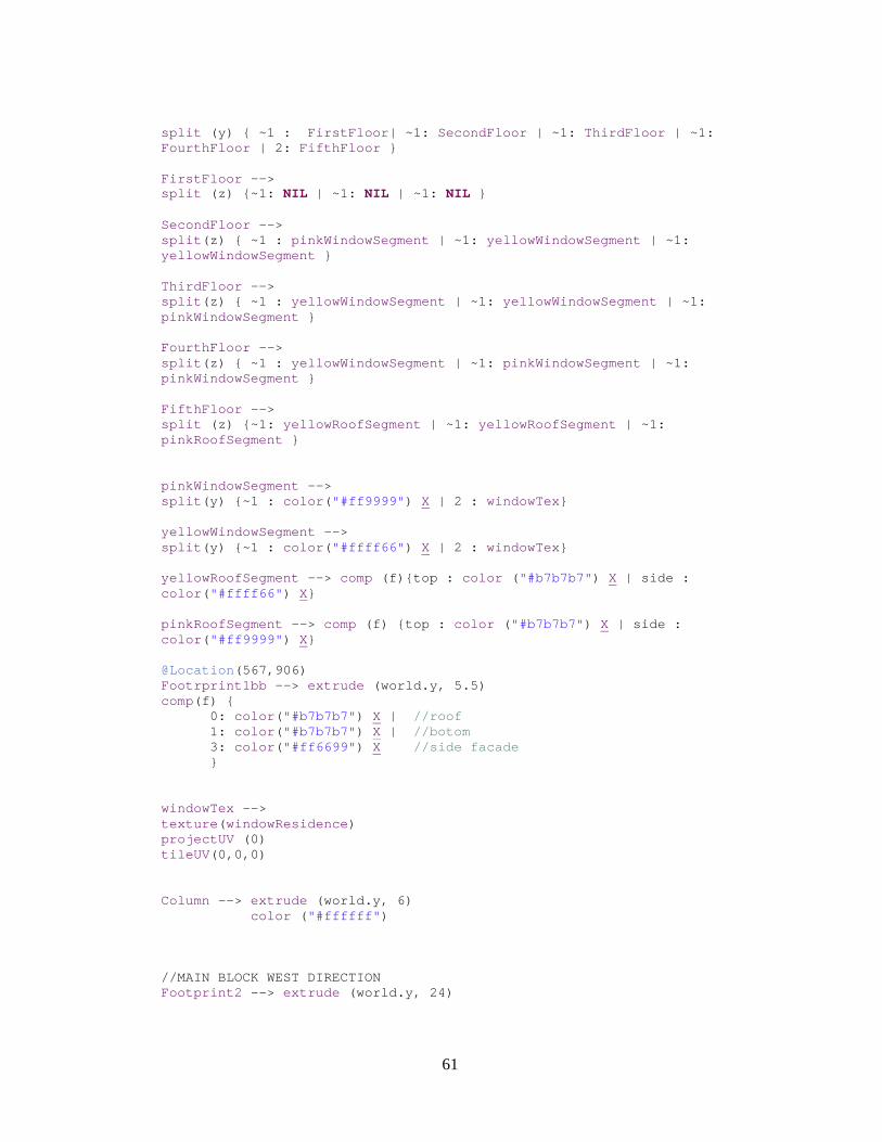
61
split (y) { ~1 : FirstFloor | ~1: SecondFloor | ~1: ThirdFloor | ~1: FourthFloor | 2: FifthFloor } FirstFloor --> split (z) {~1: NIL | ~1: NIL | ~1: NIL } SecondFloor --> split (z) { ~1 : pinkWindowSegment | ~1: yellowWindowSegment | ~1: yellowWindowSegment } ThirdFloor --> split (z) { ~1 : yellowWindowSegment | ~1: yellowWindowSegment | ~1: pinkWindowSegment } FourthFloor --> split (z) { ~1 : yellowWindowSegment | ~1: pinkWindowSegment | ~1: pinkWindowSegment } FifthFloor --> split (z) {~1: yellowRoofSegment | ~1: yellowRoofSegment | ~1: pinkRoofSegment } pinkWindowSegment --> split (y) {~1 : color ( "#ff9999" ) X | 2 : windowTex } yellowWindowSegment --> split (y) {~1 : color ( "#ffff66" ) X | 2 : windowTex } yellowRoofSegment --> comp (f){top : color ( "#b7b7b7" ) X | side : color ( "#ffff66" ) X} pinkRoofSegment --> comp (f) {top : color ( "#b7b7b7" ) X | side : color ( "#ff9999" ) X} @Location (567,906) Footrprint1bb --> extrude (world.y, 5.5) comp(f) { 0: color ( "#b7b7b7" ) X | //roof 1: color ( "#b7b7b7" ) X | //botom 3: color ( "#ff6699" ) X //side facade } windowTex --> texture ( windowResidence ) projectUV (0) tileUV (0,0,0) Column --> extrude (world.y, 6) color ( "#ffffff" ) //MAIN BLOCK WEST DIRECTION Footprint2 --> extrude (world.y, 24)
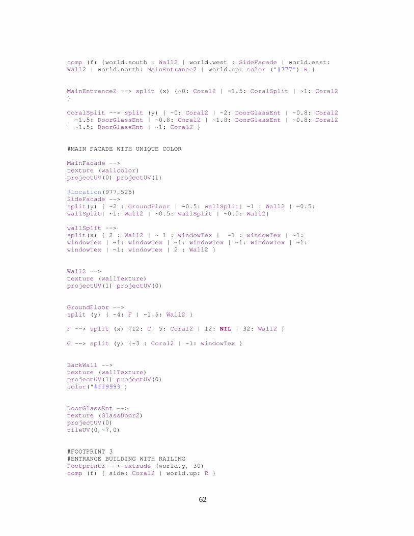
62
comp (f) {world.south : Wall2 | world.west : SideFacade | world.east: Wall2 | world.north: MainEntrance2 | world.up: color ( "#777" ) R } MainEntrance2 --> split (x) {~0: Coral2 | ~1.5: CoralSplit | ~1: Coral2 } CoralSplit --> split (y) { ~0: Coral2 | ~2: DoorGlassEnt | ~0.8: Coral2 | ~1.5: DoorGlassEnt | ~0.8: Coral2 | ~1.8: DoorGlassEnt | ~0.8: Coral2 | ~1.5: DoorGlassEnt | ~1: Coral2 } #MAIN FACADE WITH UNIQUE COLOR MainFacade --> texture ( wallcolor ) projectUV (0) projectUV (1) @Location (977,525) SideFacade --> split (y) { ~2 : GroundFloor | ~0.5: wallSplit | ~1 : Wall2 | ~0.5: wallSplit | ~1: Wall2 | ~0.5: wallSplit | ~0.5: Wall2 } wallSplit --> split (x) { 2 : Wall2 | ~ 1 : windowTex | ~1 : windowTex | ~1: windowTex | ~1: windowTex | ~1: windowTex | ~1: windowTex | ~1: windowTex | ~1: windowTex | 2 : Wall2 } Wall2 --> texture ( wallTexture ) projectUV (1) projectUV (0) GroundFloor --> split (y) { ~4: F | ~1.5: Wall2 } F --> split (x) {12: C| 5: Coral2 | 12: NIL | 32: Wall2 } C --> split (y) {~3 : Coral2 | ~1: windowTex } BackWall --> texture ( wallTexture ) projectUV (1) projectUV (0) color ( "#ff9999" ) DoorGlassEnt --> texture ( GlassDoor2 ) projectUV (0) tileUV (0,~7,0) #FOOTPRINT 3 #ENTRANCE BUILDING WITH RAILING Footprint3 --> extrude (world.y, 30) comp (f) { side: Coral2 | world.up: R }

63
Coral2 --> color ( "#E55B3C" ) MainEntrance --> extrude (world.y, 6.1) comp (f) {world.north: split (y) { ~1: Railing | ~1: NIL } | world.west: NIL | world.up: Extra } Extra --> s('1, '1, 0.3) i ( "builtin:cube" ) Railing --> [ t (0, scope.sy- barDiameter/1,0) HBar ] set ( trim.vertical, false) split (x){ 3 : VBar }* VBar --> s( barDiameter,'0, barDiameter) t (0,0,- barDiameter) i ( cyl_v) color ( "#6E6A6B" ) HBar --> s('1, barDiameter, barDiameter) t (0,0,- barDiameter) i ( cyl_h) color ( "#6E6A6B" ) @Location (1094,183) //SideFacade S--> setupProjection (0, world.xy, 1.5, 1, 1) setupProjection (2, world.xy, scope.sx, scope.sy) @Location (904,328) R --> setupProjection (1, world.xy, scope.sx, scope.sy) projectUV (0)
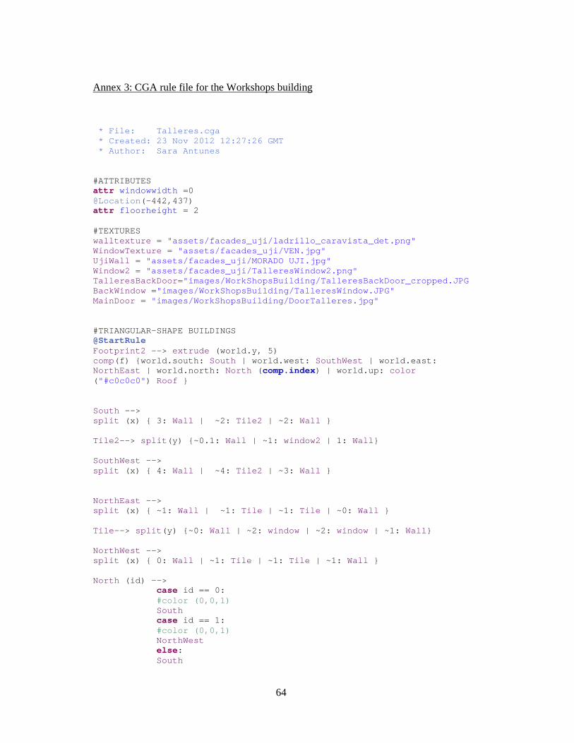
64
Annex 3: CGA rule file for the Workshops building
* File: Talleres.cga * Created: 23 Nov 2012 12:27:26 GMT * Author: Sara Antunes #ATTRIBUTES attr windowwidth =0 @Location (-442,437) attr floorheight = 2 #TEXTURES walltexture = "assets/facades_uji/ladrillo_caravista_det.png" WindowTexture = "assets/facades_uji/VEN.jpg" UjiWall = "assets/facades_uji/MORADO UJI.jpg" Window2 = "assets/facades_uji/TalleresWindow2.png" TalleresBackDoor ="images/WorkShopsBuilding/TalleresBackDoor_cropped. JPG BackWindow = "images/WorkShopsBuilding/TalleresWindow.JPG" MainDoor = "images/WorkShopsBuilding/DoorTalleres.jpg" #TRIANGULAR-SHAPE BUILDINGS @StartRule Footprint2 --> extrude (world.y, 5) comp(f) {world.south: South | world.west: SouthWest | world.east: NorthEast | world.north: North ( comp.index) | world.up: color ( "#c0c0c0" ) Roof } South --> split (x) { 3: Wall | ~2: Tile2 | ~2: Wall } Tile2 --> split (y) {~0.1: Wall | ~1: window2 | 1: Wall } SouthWest --> split (x) { 4: Wall | ~4: Tile2 | ~3: Wall } NorthEast --> split (x) { ~1: Wall | ~1: Tile | ~1: Tile | ~0: Wall } Tile --> split (y) {~0: Wall | ~2: window | ~2: window | ~1: Wall } NorthWest --> split (x) { 0: Wall | ~1: Tile | ~1: Tile | ~1: Wall } North (id) --> case id == 0: #color (0,0,1) South case id == 1: #color (0,0,1) NorthWest else: South
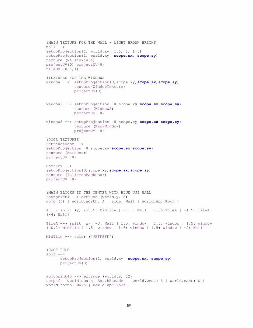
65
#MAIN TEXTURE FOR THE WALL – LIGHT BROWN BRICKS Wall --> setupProjection (1, world.xy, 1.5, 1, 1.5) setupProjection (1, world.xy, scope.sx, scope.sy) texture ( walltexture ) projectUV (0) projectUV (0) tileUV (0,1,1) #TEXTURES FOR THE WINDOWS window --> setupProjection (0,scope.xy, scope.sx, scope.sy) texture ( WindowTexture ) projectUV (0) window2 --> setupProjection (0,scope.xy, scope.sx, scope.sy) texture ( Window2) projectUV (0) window3 --> setupProjection (0,scope.xy, scope.sx, scope.sy) texture ( BackWindow ) projectUV (0) #DOOR TEXTURES EntranceDoor --> setupProjection (0,scope.xy, scope.sx, scope.sy) texture ( MainDoor ) projectUV (0) DoorTex --> setupProjection (0,scope.xy, scope.sx, scope.sy) texture ( TalleresBackDoor ) projectUV (0) #MAIN BLOCKS IN THE CENTER WITH BLUE UJI WALL Footprint4 --> extrude (world.y, 8) comp (f) { world.north: A | side: Wall | world.up: Roof } A --> split (y) {~0.5: MidTile | ~1.5: Wall | ~1.5: TileA | ~1.5: TileA |~4: Wall } TileA --> split (x) {~3: Wall | 1.5: window | 1.5: window | 1.5: window | 0.2: MidTile | 1.5: window | 1.5: window | 1.5: window | ~2: Wall } MidTile --> color ( "#FFFFFF" ) #ROOF RULE Roof --> setupProjection (1, world.xy, scope.sx, scope.sy) projectUV (0) Footprint4b --> extrude (world.y, 12) comp(f) {world.south: SouthFacade | world.west: S | world.east: S | world.north: Main | world.up: Roof }
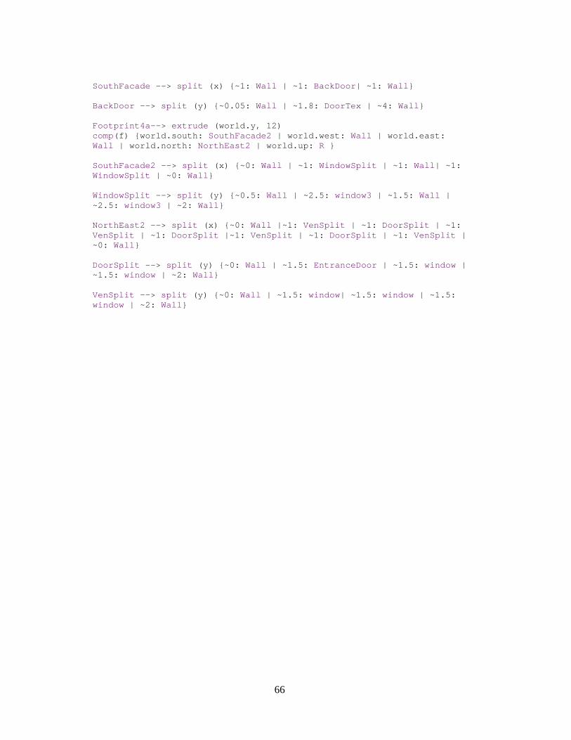
66
SouthFacade --> split (x) {~1: Wall | ~1: BackDoor | ~1: Wall } BackDoor --> split (y) {~0.05: Wall | ~1.8: DoorTex | ~4: Wall } Footprint4a --> extrude (world.y, 12) comp(f) {world.south: SouthFacade2 | world.west: Wall | world.east: Wall | world.north: NorthEast2 | world.up: R } SouthFacade2 --> split (x) {~0: Wall | ~1: WindowSplit | ~1: Wall | ~1: WindowSplit | ~0: Wall } WindowSplit --> split (y) {~0.5: Wall | ~2.5: window3 | ~1.5: Wall | ~2.5: window3 | ~2: Wall } NorthEast2 --> split (x) {~0: Wall |~1: VenSplit | ~1: DoorSplit | ~1: VenSplit | ~1: DoorSplit |~1: VenSplit | ~1: DoorSplit | ~1: VenSplit | ~0: Wall } DoorSplit --> split (y) {~0: Wall | ~1.5: EntranceDoor | ~1.5: window | ~1.5: window | ~2: Wall } VenSplit --> split (y) {~0: Wall | ~1.5: window | ~1.5: window | ~1.5: window | ~2: Wall }
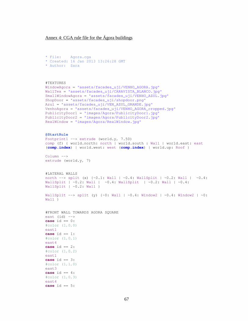
67
Annex 4: CGA rule file for the Ágora buildings
* File: Agora.cga * Created: 16 Jan 2013 13:26:28 GMT * Author: Sara #TEXTURES WindowAgora = "assets/facades_uji/VENHO_AGORA.jpg" WallTex = "assets/facades_uji/CARAVISTA_BLANCO.jpg" SmallWindowAgora = "assets/facades_uji/VENHO_AZUL.jpg" ShopDoor = "assets/facades_uji/shopdoor.png" Azul = "assets/facades_uji/VEN_AZUL_GRANDE.jpg" VenhoAgora = "assets/facades_uji/VENHO_AGORA_cropped.jpg" PublicityDoor1 = "images/Agora/PublicityDoor1.jpg" PublicityDoor2 = "images/Agora/PublicityDoor2.jpg" RealWindow = "images/Agora/RealWindow.jpg" @StartRule Footprint1 --> extrude (world.y, 7.50) comp (f) { world.north: north | world.south : Wall | world.east: east ( comp.index) | world.west: west ( comp.index) | world.up: Roof } Column --> extrude (world.y, 7) #LATERAL WALLS north --> split (x) {~0.1: Wall | ~0.4: WallSplit | ~0.2: Wall | ~0.4: WallSplit | ~0.2: Wall | ~0.4: WallSplit | ~0.2: Wall | ~0.4: WallSplit | ~0.2: Wall } WallSplit --> split (y) {~0: Wall | ~0.4: Window2 | ~0.4: Window2 | ~0: Wall } #FRONT WALL TOWARDS AGORA SQUARE east (id) --> case id == 0: #color (1,0,0) east1 case id == 1: #color (1,0,1) east4 case id == 2: #color (1,0,2) east1 case id == 3: #color (1,1,0) east3 case id == 4: #color (1,0,3) east4 case id == 5:
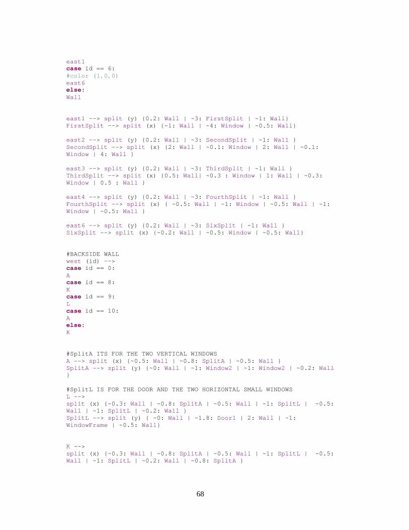
68
east1 case id == 6: #color (1,0,0) east6 else: Wall east1 --> split (y) {0.2: Wall | ~3: FirstSplit | ~1: Wall } FirstSplit --> split (x) {~1: Wall | ~4: Window | ~0.5: Wall } east2 --> split (y) {0.2: Wall | ~3: SecondSplit | ~1: Wall } SecondSplit --> split (x) {2: Wall | ~0.1: Window | 2: Wall | ~0.1: Window | 4: Wall } east3 --> split (y) {0.2: Wall | ~3: ThirdSplit | ~1: Wall } ThirdSplit --> split (x) {0.5: Wall | ~0.3 : Window | 1: Wall | ~0.3: Window | 0.5 : Wall } east4 --> split (y) {0.2: Wall | ~3: FourthSplit | ~1: Wall } FourthSplit --> split (x) { ~0.5: Wall | ~1: Window | ~0.5: Wall | ~1: Window | ~0.5: Wall } east6 --> split (y) {0.2: Wall | ~3: SixSplit | ~1: Wall } SixSplit --> split (x) {~0.2: Wall | ~0.5: Window | ~0.5: Wall } #BACKSIDE WALL west (id) --> case id == 0: A case id == 8: K case id == 9: L case id == 10: A else: K #SplitA ITS FOR THE TWO VERTICAL WINDOWS A --> split (x) {~0.5: Wall | ~0.8: SplitA | ~0.5: Wall } SplitA --> split (y) {~0: Wall | ~1: Window2 | ~1: Window2 | ~0.2: Wall } #SplitL IS FOR THE DOOR AND THE TWO HORIZONTAL SMAL L WINDOWS L --> split (x) {~0.3: Wall | ~0.8: SplitA | ~0.5: Wall | ~1: SplitL | ~0.5: Wall | ~1: SplitL | ~0.2: Wall } SplitL --> split (y) { ~0: Wall | ~1.8: Door1 | 2: Wall | ~1: WindowFrame | ~0.5: Wall } K --> split (x) {~0.3: Wall | ~0.8: SplitA | ~0.5: Wall | ~1: SplitL | ~0.5: Wall | ~1: SplitL | ~0.2: Wall | ~0.8: SplitA }
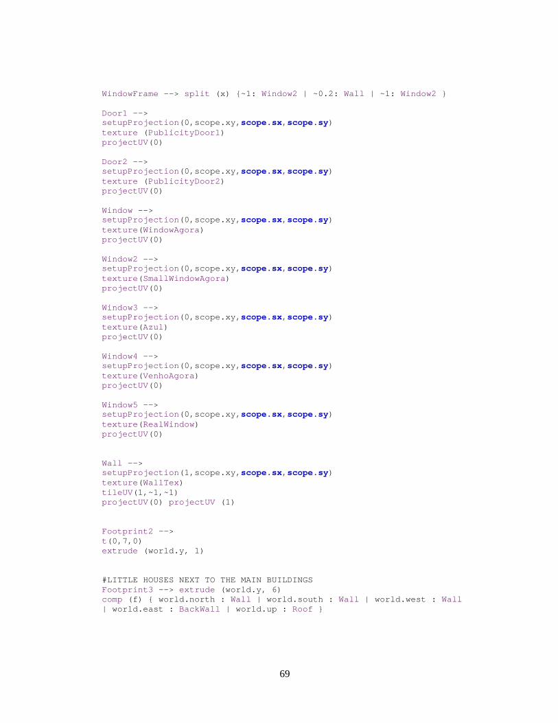
69
WindowFrame --> split (x) {~1: Window2 | ~0.2: Wall | ~1: Window2 } Door1 --> setupProjection (0,scope.xy, scope.sx, scope.sy) texture ( PublicityDoor1 ) projectUV (0) Door2 --> setupProjection (0,scope.xy, scope.sx, scope.sy) texture ( PublicityDoor2 ) projectUV (0) Window --> setupProjection (0,scope.xy, scope.sx, scope.sy) texture ( WindowAgora ) projectUV (0) Window2 --> setupProjection (0,scope.xy, scope.sx, scope.sy) texture ( SmallWindowAgora ) projectUV (0) Window3 --> setupProjection (0,scope.xy, scope.sx, scope.sy) texture ( Azul ) projectUV (0) Window4 --> setupProjection (0,scope.xy, scope.sx, scope.sy) texture ( VenhoAgora ) projectUV (0) Window5 --> setupProjection (0,scope.xy, scope.sx, scope.sy) texture ( RealWindow ) projectUV (0) Wall --> setupProjection (1,scope.xy, scope.sx, scope.sy) texture ( WallTex ) tileUV (1,~1,~1) projectUV (0) projectUV (1) Footprint2 --> t (0,7,0) extrude (world.y, 1) #LITTLE HOUSES NEXT TO THE MAIN BUILDINGS Footprint3 --> extrude (world.y, 6) comp (f) { world.north : Wall | world.south : Wall | world.west : Wall | world.east : BackWall | world.up : Roof }
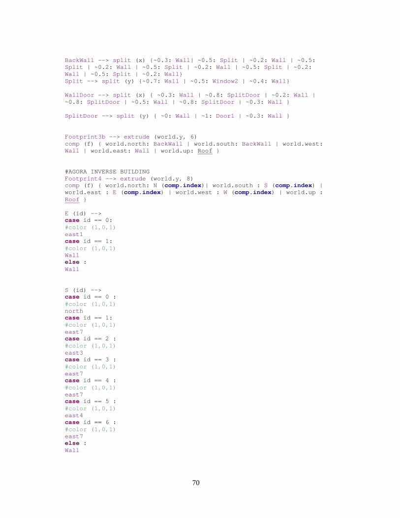
70
BackWall --> split (x) {~0.3: Wall | ~0.5: Split | ~0.2: Wall | ~0.5: Split | ~0.2: Wall | ~0.5: Split | ~0.2: Wall | ~0.5: Split | ~0.2: Wall | ~0.5: Split | ~0.2: Wall } Split --> split (y) {~0.7: Wall | ~0.5: Window2 | ~0.4: Wall } WallDoor --> split (x) { ~0.3: Wall | ~0.8: SplitDoor | ~0.2: Wall | ~0.8: SplitDoor | ~0.5: Wall | ~0.8: SplitDoor | ~0.3: Wall } SplitDoor --> split (y) { ~0: Wall | ~1: Door1 | ~0.3: Wall } Footprint3b --> extrude (world.y, 6) comp (f) { world.north: BackWall | world.south: BackWall | world.west: Wall | world.east: Wall | world.up: Roof } #AGORA INVERSE BUILDING Footprint4 --> extrude (world.y, 8) comp (f) { world.north: N ( comp.index)| world.south : S ( comp.index) | world.east : E ( comp.index) | world.west : W ( comp.index) | world.up : Roof } E (id) --> case id == 0: #color (1,0,1) east1 case id == 1: #color (1,0,1) Wall else : Wall S (id) --> case id == 0 : #color (1,0,1) north case id == 1: #color (1,0,1) east7 case id == 2 : #color (1,0,1) east3 case id == 3 : #color (1,0,1) east7 case id == 4 : #color (1,0,1) east7 case id == 5 : #color (1,0,1) east4 case id == 6 : #color (1,0,1) east7 else : Wall
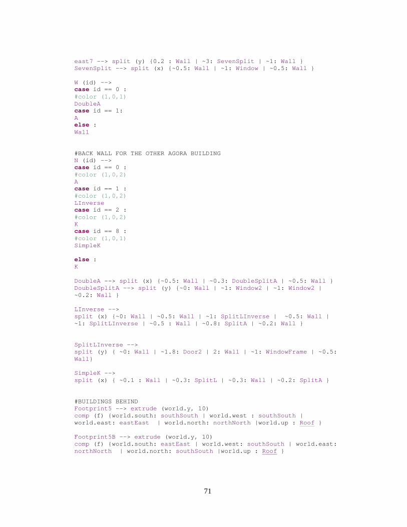
71
east7 --> split (y) {0.2 : Wall | ~3: SevenSplit | ~1: Wall } SevenSplit --> split (x) {~0.5: Wall | ~1: Window | ~0.5: Wall } W (id) --> case id == 0 : #color (1,0,1) DoubleA case id == 1: A else : Wall #BACK WALL FOR THE OTHER AGORA BUILDING N (id) --> case id == 0 : #color (1,0,2) A case id == 1 : #color (1,0,2) LInverse case id == 2 : #color (1,0,2) K case id == 8 : #color (1,0,1) SimpleK else : K DoubleA --> split (x) {~0.5: Wall | ~0.3: DoubleSplitA | ~0.5: Wall } DoubleSplitA --> split (y) {~0: Wall | ~1: Window2 | ~1: Window2 | ~0.2: Wall } LInverse --> split (x) {~0: Wall | ~0.5: Wall | ~1: SplitLInverse | ~0.5: Wall | ~1: SplitLInverse | ~0.5 : Wall | ~0.8: SplitA | ~0.2: Wall } SplitLInverse --> split (y) { ~0: Wall | ~1.8: Door2 | 2: Wall | ~1: WindowFrame | ~0.5: Wall } SimpleK --> split (x) { ~0.1 : Wall | ~0.3: SplitL | ~0.3: Wall | ~0.2: SplitA } #BUILDINGS BEHIND Footprint5 --> extrude (world.y, 10) comp (f) {world.south: southSouth | world.west : southSouth | world.east: eastEast | world.north: northNorth |world.up : Roof } Footprint5B --> extrude (world.y, 10) comp (f) {world.south: eastEast | world.west: southSouth | world.east: northNorth | world.north: southSouth |world.up : Roof }
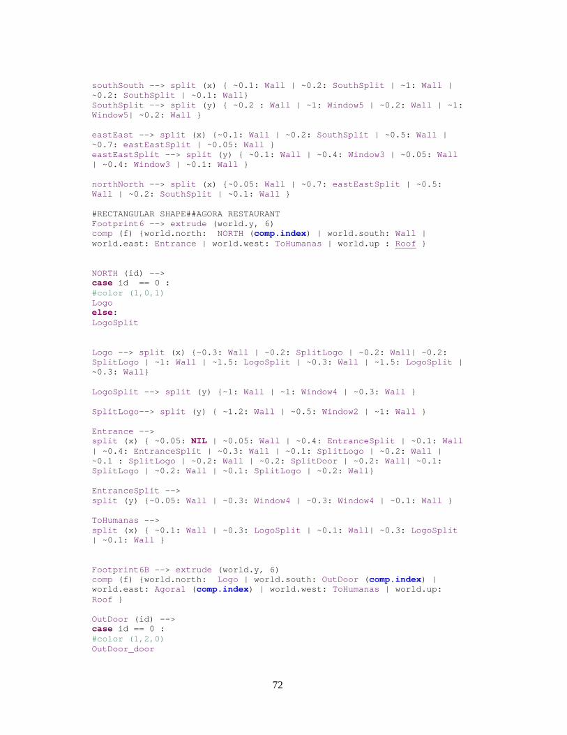
72
southSouth --> split (x) { ~0.1: Wall | ~0.2: SouthSplit | ~1: Wall | ~0.2: SouthSplit | ~0.1: Wall } SouthSplit --> split (y) { ~0.2 : Wall | ~1: Window5 | ~0.2: Wall | ~1: Window5| ~0.2: Wall } eastEast --> split (x) {~0.1: Wall | ~0.2: SouthSplit | ~0.5: Wall | ~0.7: eastEastSplit | ~0.05: Wall } eastEastSplit --> split (y) { ~0.1: Wall | ~0.4: Window3 | ~0.05: Wall | ~0.4: Window3 | ~0.1: Wall } northNorth --> split (x) {~0.05: Wall | ~0.7: eastEastSplit | ~0.5: Wall | ~0.2: SouthSplit | ~0.1: Wall } #RECTANGULAR SHAPE##AGORA RESTAURANT Footprint6 --> extrude (world.y, 6) comp (f) {world.north: NORTH ( comp.index) | world.south: Wall | world.east: Entrance | world.west: ToHumanas | world.up : Roof } NORTH (id) --> case id == 0 : #color (1,0,1) Logo else: LogoSplit Logo --> split (x) {~0.3: Wall | ~0.2: SplitLogo | ~0.2: Wall | ~0.2: SplitLogo | ~1: Wall | ~1.5: LogoSplit | ~0.3: Wall | ~1.5: LogoSplit | ~0.3: Wall } LogoSplit --> split (y) {~1: Wall | ~1: Window4 | ~0.3: Wall } SplitLogo --> split (y) { ~1.2: Wall | ~0.5: Window2 | ~1: Wall } Entrance --> split (x) { ~0.05: NIL | ~0.05: Wall | ~0.4: EntranceSplit | ~0.1: Wall | ~0.4: EntranceSplit | ~0.3: Wall | ~0.1: SplitLogo | ~0.2: Wall | ~0.1 : SplitLogo | ~0.2: Wall | ~0.2: SplitDoor | ~0.2: Wall | ~0.1: SplitLogo | ~0.2: Wall | ~0.1: SplitLogo | ~0.2: Wall } EntranceSplit --> split (y) {~0.05: Wall | ~0.3: Window4 | ~0.3: Window4 | ~0.1: Wall } ToHumanas --> split (x) { ~0.1: Wall | ~0.3: LogoSplit | ~0.1: Wall | ~0.3: LogoSplit | ~0.1: Wall } Footprint6B --> extrude (world.y, 6) comp (f) {world.north: Logo | world.south: OutDoor ( comp.index) | world.east: Agora1 ( comp.index) | world.west: ToHumanas | world.up: Roof } OutDoor (id) --> case id == 0 : #color (1,2,0) OutDoor_door
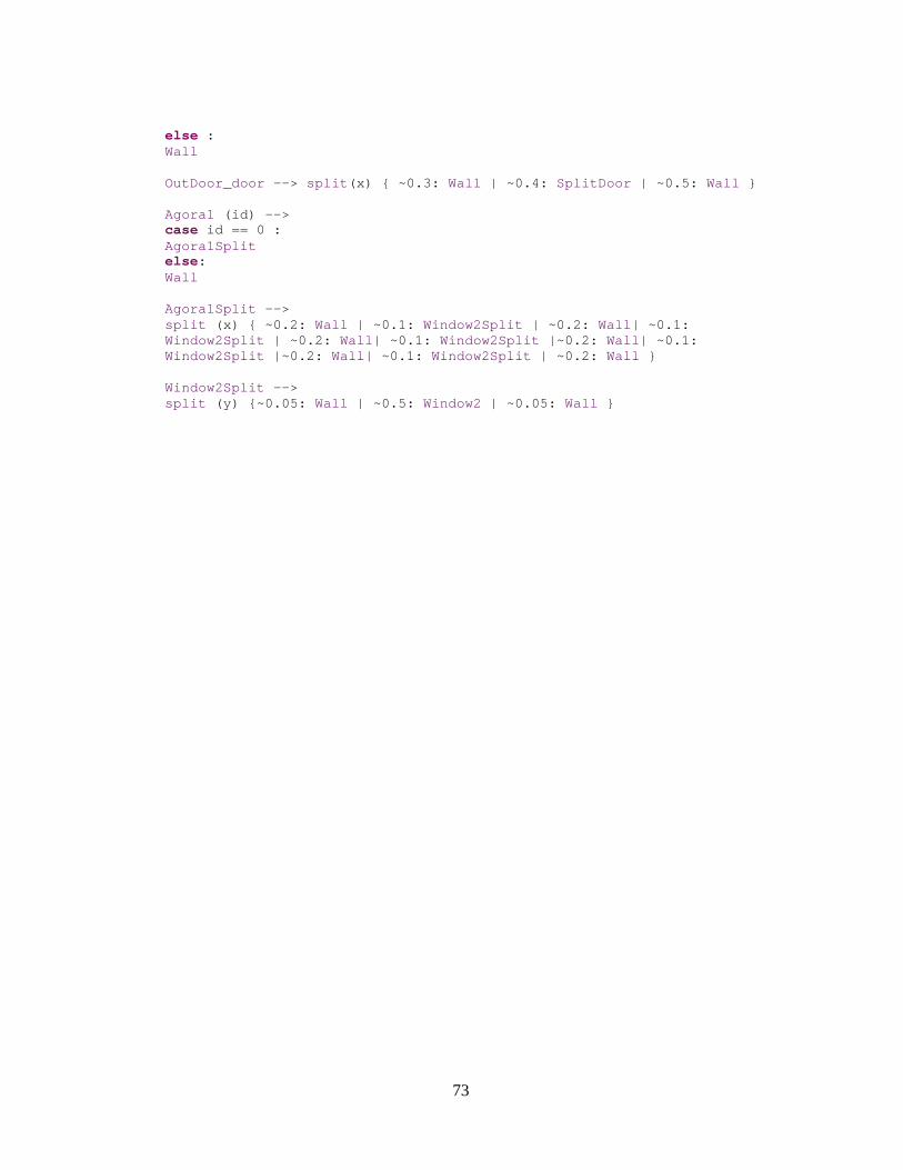
73
else : Wall OutDoor_door --> split (x) { ~0.3: Wall | ~0.4: SplitDoor | ~0.5: Wall } Agora1 (id) --> case id == 0 : Agora1Split else: Wall Agora1Split --> split (x) { ~0.2: Wall | ~0.1: Window2Split | ~0.2: Wall | ~0.1: Window2Split | ~0.2: Wall | ~0.1: Window2Split |~0.2: Wall | ~0.1: Window2Split |~0.2: Wall | ~0.1: Window2Split | ~0.2: Wall } Window2Split --> split (y) {~0.05: Wall | ~0.5: Window2 | ~0.05: Wall }


1