Embed Size (px)
Citation preview

Operating ManualOperating Manual
™
VIPERVehicle Information Processing

Operating Manual
Viper™ Vehicular Information Processing,
Export, and Reporting Software
12/10/2010 p/n: 99-550 Rev 1

Viper Operating Manual assembly: 81-1331 Viper Operating Manual content: 99-550 Viper Operating Manual cover art: 99-551
Copyright © 2010 Peek Traffic Corporation All rights reserved. Information furnished by Peek Traffic is believed to be accurate and reliable, however Peek does not warranty the accuracy, completeness, or fitness for use of any of the information furnished. No license is granted by implication or otherwise under any intellectual property. Peek reserves the right to alter any of the Company's products or published technical data relating thereto at any time without notice. No part of this publication may be reproduced, stored in a retrieval system, or transmitted in any form or via any electronic or mechanical means for any purpose other than the purchaser’s personal use without the expressed, written permission of Peek Traffic Corporation. Peek Traffic Corporation 2906 Corporate Way Palmetto, FL 34221 U.S.A. Trademarks Viper, the Viper logo, ADR Plus, the ADR Plus logo, ADR-1000 Plus, ADR-2000 Plus, ADR-3000 Plus, StopWatch+, TOPS, IQ Data, AxleLight, SmartToll, and ADR-6000 are trademarks or registered trademarks of Peek Traffic Corporation, in the USA and other countries. Microsoft and Windows are trademarks or registered trademarks of Microsoft Corporation. Idris is a trademark or registered trademark of Diamond Consulting Services, plc. Crystal Reports and Crystal Solutions are trademarks or registered trademarks of SAP. Other brands and their products are trademarks or registered trademarks of their respective holders and should be noted as such.

Viper Vehicular Information Processing Software iii
Contents
Preface — About This Manual.......................................................................................... 1
Purpose and Scope ............................................................................................................................ 1 Assumptions ....................................................................................................................................... 1 Related Documents ............................................................................................................................ 2 Technical Assistance .......................................................................................................................... 2 Conventions Used in this Manual ....................................................................................................... 3
Typographic Conventions ................................................................................................................ 3 Keyboard and Menu Conventions ................................................................................................... 3 Symbol Conventions........................................................................................................................ 4
Chapter 1 — Introduction to Viper................................................................................... 5 Overview............................................................................................................................................. 6 Typical Environment ........................................................................................................................... 7 WorkFlow when Using Viper............................................................................................................... 8
Chapter 2 — Installing Viper .......................................................................................... 11 Overview........................................................................................................................................... 12 Preparing for the Install..................................................................................................................... 12 Installing Viper .................................................................................................................................. 13 Next Steps ........................................................................................................................................ 14
Chapter 3 — Using the Viper Interface.......................................................................... 15 Overview........................................................................................................................................... 16 Viper Front End................................................................................................................................. 17
Launching the Viper Front End Application ................................................................................... 18 TOPS Data Migration Utility.............................................................................................................. 21 Windows Services ............................................................................................................................ 22
Peek Scheduler Service ................................................................................................................ 23 Peek Auto-Processing Service ...................................................................................................... 25
Chapter 4 — Managing Communications ..................................................................... 29 Overview........................................................................................................................................... 30
Available Communications Options............................................................................................... 30

iv Viper Vehicular Information Processing Software
Using the Communications Channels Panel .................................................................................... 31 Summary View............................................................................................................................... 32 Simple Editing View....................................................................................................................... 33 Advanced Editing View.................................................................................................................. 34
Adding Channels .............................................................................................................................. 35 Adding a Serial Port Channel ........................................................................................................ 35 Adding a Modem Channel ............................................................................................................. 36 Adding a Serial Modem Bank Channel.......................................................................................... 36 Adding an IP Network Stream Channel ......................................................................................... 37 Adding a Permanent IP Channel ................................................................................................... 37 Adding a Dial-Up IP channel ......................................................................................................... 38
Editing a Communications Channel.................................................................................................. 39 Deleting a Communications Channel ............................................................................................... 41 Channel Parameters......................................................................................................................... 43
Serial Channel via a Physical Port ................................................................................................ 43 Serial Channel via a Modem ......................................................................................................... 44 Serial Channel via a Modem Bank ................................................................................................46 IP Network Stream......................................................................................................................... 46 Permanent IP Channel .................................................................................................................. 47 Dial-Up IP Channel ........................................................................................................................ 47
Configuring IP Routing...................................................................................................................... 48 Why are Route rules necessary? .................................................................................................. 48 The ROUTE command .................................................................................................................. 48 Adding a routing rule for a dial- up unit.......................................................................................... 48 Making a routing rule permanent................................................................................................... 49 Routing rules for permanently connected devices......................................................................... 49
Chapter 5 — Managing Devices.....................................................................................51 Overview........................................................................................................................................... 52 Using the Devices Pane ................................................................................................................... 53
Summary View............................................................................................................................... 53 Adding a Device................................................................................................................................ 57
Adding an ADR 1000, 2000, or 3000 to Viper ............................................................................... 57 Adding an ADR 6000 to Viper........................................................................................................ 59
Editing a Device................................................................................................................................ 61 Deleting a Device.............................................................................................................................. 62 Device Parameters ........................................................................................................................... 64
Device Parameters ........................................................................................................................ 65 Chapter 6 — Auto Processing........................................................................................91
Overview........................................................................................................................................... 92 Using the Automatic Processing Pane ............................................................................................. 93
Launching the Auto-Processing Module ........................................................................................ 94 Auto-Processing Work Environment.............................................................................................. 95
Available Processing Components ................................................................................................. 106 Creating an Automatic Processing Plan ......................................................................................... 119
Default Configuration................................................................................................................... 119 Error Handling ............................................................................................................................. 122 Setting a Watch Folder Trigger .................................................................................................... 123 Merging ADR Binned data ........................................................................................................... 123 Sorting Data Files by Type........................................................................................................... 131 Adjusting Binned Data for Daylight Savings Time Changes........................................................ 131 Generating XML from ADR Binned Data ..................................................................................... 132 Move File Task............................................................................................................................. 133 Generating a Report from Binned Data ....................................................................................... 134

Viper Vehicular Information Processing Software v
Chapter 7 — Scheduling Activity ................................................................................. 135 Overview......................................................................................................................................... 136 Scheduled Tasks Interface ............................................................................................................. 137
Summary View ............................................................................................................................ 137 Task Editing Window ................................................................................................................... 140
Adding a Scheduled Task............................................................................................................... 146 Modifying a Scheduled Task........................................................................................................... 147 Monitoring a Scheduled Task ......................................................................................................... 147 Deleting a Scheduled Task............................................................................................................. 148
Chapter 8 — Exporting Data......................................................................................... 149 Overview – Exporting Data from Viper ........................................................................................... 150 Generating a PRN Export ............................................................................................................... 151
Adding the Write PRN Action....................................................................................................... 151 Setting PRN File Names.............................................................................................................. 155 Setting PRN Export Parameters.................................................................................................. 157 Activating the PRN Export Plan................................................................................................... 159
Generating an XML Export ............................................................................................................. 160 Adding the Write XML Action....................................................................................................... 160 Setting XML File Names and Activating the Plan ........................................................................ 164
Generating a TMG Export............................................................................................................... 166 Adding the Write TMG Action ...................................................................................................... 166 Configuring Devices for TMG S-Card Export .............................................................................. 170 Setting TMG Export Parameters ................................................................................................. 171 Activating the TMG Export Plan .................................................................................................. 173
Generating a Viper Report.............................................................................................................. 174 Adding the Generate Report Action............................................................................................. 175 Setting Report Options ................................................................................................................ 179 Activating the Report Plan ........................................................................................................... 181 Example Reports ......................................................................................................................... 182
Chapter 9 — System Maintenance............................................................................... 189 System Settings.............................................................................................................................. 190
File Storage Paths ....................................................................................................................... 190 Units Selection............................................................................................................................. 193 System Archiving ......................................................................................................................... 193
Activity Logging............................................................................................................................... 195 Refreshing the Log View ............................................................................................................. 197 Configuring System Logs ............................................................................................................ 197
Troubleshooting .............................................................................................................................. 198 Viper Version Information ............................................................................................................ 198 Technical Assistance ................................................................................................................... 199 Troubleshooting Checklist ........................................................................................................... 199
Uninstalling Viper............................................................................................................................ 202 Glossary......................................................................................................................... 205 Index............................................................................................................................... 215

vi Viper Vehicular Information Processing Software
Table of Figures Figure 1 – Verify that the Viper application has been properly installed ............................................................................14 Figure 2 – Relationship of the Viper interfaces to operating elements...............................................................................16 Figure 3 – Viper Front End interface start screen..............................................................................................................18 Figure 4 – Panel Address Bar for the About panel ............................................................................................................20 Figure 5 – Pulling up the data for a particular device using the address bar......................................................................20 Figure 6 – TOPS Migration Utility data conversion step ....................................................................................................21 Figure 7 – TOS Migration Utility – Conversion Complete ..................................................................................................21 Figure 8 – Peek services in the Computer Management window ......................................................................................22 Figure 9 – Peek Scheduler Service – General settings .....................................................................................................23 Figure 10 – Peek Scheduler Service – Log On settings ....................................................................................................24 Figure 11 – Peek Scheduler Service – Recovery settings.................................................................................................24 Figure 12 – Peek Scheduler Service - Dependencies .......................................................................................................25 Figure 13 – Peek State Machine Service – General settings.............................................................................................26 Figure 14 – Peek State Machine Service – Log On settings .............................................................................................26 Figure 15 – Peek State Machine Service – Recovery settings ..........................................................................................27 Figure 16 – Peek State Machine Service – Dependencies................................................................................................27 Figure 17 – Comm Channels Pane – List view..................................................................................................................31 Figure 18 – Communications Channels pane – Details view.............................................................................................32 Figure 19 – Add and Delete buttons in Channels-Summary panel ....................................................................................33 Figure 20 – Simple editing panel for a Serial channel .......................................................................................................33 Figure 21 – Advanced tab of the Channel pane for a Serial channel.................................................................................34 Figure 22 – Add and Delete buttons in Channels-Summary pane.....................................................................................35 Figure 23 – New Channel dialog box ................................................................................................................................35 Figure 24 – Editing in the Advanced Channel environment...............................................................................................39 Figure 25 – Comms Channels:Summary view with one channel selected.........................................................................41 Figure 26 – Delete channel button ....................................................................................................................................42 Figure 27 – Verify the delete request ................................................................................................................................42 Figure 28 – Devices Pane – List view ...............................................................................................................................53 Figure 29 – Devices Pane – Details view ..........................................................................................................................54 Figure 30 – Add and Delete buttons in Device-Summary pane .........................................................................................54 Figure 31 – View options in the Devices pane – Tile view shown......................................................................................55 Figure 32 – Icon indicating an invalid ADR-6000 device configuration ..............................................................................56 Figure 33 – New Device dialog box...................................................................................................................................57 Figure 34 – Devices – Summary view with one device selected .......................................................................................62 Figure 35 – Delete device button ......................................................................................................................................62 Figure 36 – Verify the delete request ................................................................................................................................63 Figure 37 – New Device dialog box...................................................................................................................................64 Figure 38 – Available Tabs in Viper for an ADR-6000 device............................................................................................65 Figure 39 – Device Parameters – Identification Tab..........................................................................................................66 Figure 40 – Device Parameters – Connection Tab – Peek ADR Devices..........................................................................68 Figure 41 – Device Parameters – Connection Tab – ADR-6000 Devices..........................................................................68 Figure 42 – Device-specific channel settings dialog box - IP.............................................................................................69 Figure 43 – Device-specific channel settings dialog box – Dialup .....................................................................................69 Figure 44 – Device Parameters – Operations Tab ............................................................................................................72 Figure 45 – Checking device time – Time is correct..........................................................................................................73 Figure 46 – Checking device time – Times do not match ..................................................................................................74 Figure 47 – Setting device time when the device is busy ..................................................................................................74 Figure 48 – Device Parameters – Site Tab .......................................................................................................................75 Figure 49 – Adding additional arrays to the device............................................................................................................76 Figure 50 – Device Parameters – Binned Tab...................................................................................................................77 Figure 51 – Adding a second dimension with 3 bins .........................................................................................................79 Figure 52 – Device Parameters – PVR Tab – Recording OFF ..........................................................................................80 Figure 53 – Device Parameters – PVR Tab – Recording ON............................................................................................81 Figure 54 – Device Parameters – Miscellaneous Tab .......................................................................................................84 Figure 55 – Device Parameters – TMG Tab......................................................................................................................85 Figure 56 – A sample processing workflow .......................................................................................................................93 Figure 57 – Automatic Processing pane............................................................................................................................94 Figure 58 – Auto-processing controls................................................................................................................................95 Figure 59 – Action library of the auto-processing panel.....................................................................................................96 Figure 60 – Action library – Tree view...............................................................................................................................97 Figure 61 – Identify steps to connect ................................................................................................................................98
Viper Vehicular Information Processing Software vii
Figure 62 – Select a flow point..........................................................................................................................................98 Figure 63 – Drag a connecting line ...................................................................................................................................98 Figure 64 – Drop the line on a flow point...........................................................................................................................99 Figure 65 – Completed connection between two steps .....................................................................................................99 Figure 66 – Click a step to see move cursor ...................................................................................................................100 Figure 67 – Step in a new location..................................................................................................................................100 Figure 68 – Click on a step box to see the resize controls ..............................................................................................101 Figure 69 – The resized step box....................................................................................................................................101 Figure 70 – Selected connection line – ready to be deleted ............................................................................................102 Figure 71 – Double-click on a step to open the edit screen.............................................................................................102 Figure 72 – Color coding corners of the auto-processing plan area ................................................................................103 Figure 73 – Another color coding for a displayed plan (unchanged from file) ..................................................................104 Figure 74 – Plan changed cosmetically from its file source .............................................................................................104 Figure 75 – Plan from file with edited logic......................................................................................................................105 Figure 76 – Color coding after we send the visible plan to the service ............................................................................105 Figure 77 – Watch Folder parameters dialog box............................................................................................................106 Figure 78 – Adjust for DST parameters dialog box..........................................................................................................106 Figure 79 – Merge Data parameters dialog box ..............................................................................................................107 Figure 80 – Opening screen of the Virtual Site Creation wizard ......................................................................................108 Figure 81 – Move File parameters dialog box .................................................................................................................110 Figure 82 – Read Binned Data File parameters dialog box .............................................................................................112 Figure 83 – Sort Files by Data Type parameters dialog box............................................................................................113 Figure 84 – Write PRN parameters dialog box................................................................................................................114 Figure 85 – Write XML parameters dialog box ................................................................................................................115 Figure 86 – Generate Report parameters dialog box ......................................................................................................117 Figure 87 – Default auto-processing configuration..........................................................................................................119 Figure 88 – First workflow of the default configuration ....................................................................................................120 Figure 89 – Second workflow of the default configuration ...............................................................................................120 Figure 90 – Error handling task option ............................................................................................................................122 Figure 91 – Configuring the watched folder.....................................................................................................................123 Figure 92 – Three source sites, and how they map to a single destination site ...............................................................127 Figure 93 – Partial configuration - Merged site defines and first source site added.........................................................128 Figure 94 – Partial configuration - Second source site added .........................................................................................129 Figure 95 – Final configuration including details from all three source sites ....................................................................130 Figure 96 – Configuring the Sort Files By Type operation...............................................................................................131 Figure 97 – Configuration options for the Daylight Savings Adjustment operation ..........................................................131 Figure 98 – Configuring XML output for binned data.......................................................................................................132 Figure 99 – Configuring the Move File operation ............................................................................................................133 Figure 100 – Configuring the Binned Data Reporting operation ......................................................................................134 Figure 101 – Scheduled Tasks panel of the Viper front-end interface .............................................................................136 Figure 102 – Scheduled Tasks Pane – List view.............................................................................................................137 Figure 103 – Scheduled Tasks Pane – List view.............................................................................................................138 Figure 104 – Scheduled Tasks pane – Tiled view...........................................................................................................138 Figure 105 – Add and Delete buttons in Scheduled Tasks-Summary pane.....................................................................139 Figure 106 – Scheduled Task Editing – Simple tab.........................................................................................................140 Figure 107 – Scheduled Task Editing – Advanced tab....................................................................................................143 Figure 108 – Advanced tab of the Channel pane for a Serial channel.............................................................................144 Figure 109 – Delete button at the top of the Scheduled Task pane.................................................................................148 Figure 110 – Verify that you wish to delete the task ........................................................................................................148 Figure 111 – Auto-processing plan ready to receive a PRN export .................................................................................152 Figure 112 – Selecting the Write PRN action in the Action library ...................................................................................152 Figure 113 – Placing the Write PRN action .....................................................................................................................153 Figure 114 – Connecting to the Write PRN action...........................................................................................................153 Figure 115 – Adding an error handling action to Write PRN............................................................................................153 Figure 116 – Adding a final Move action to the PRN Export flow ....................................................................................154 Figure 117 – Settings for the Export to PRN operation ...................................................................................................155 Figure 118 – PRN Export panel ......................................................................................................................................157 Figure 119 – Auto-processing plan ready to receive an XML export ...............................................................................161 Figure 120 – Selecting the Write XML action in the Action library ...................................................................................161 Figure 121 – Placing the Write XML action .....................................................................................................................161 Figure 122 – Connecting to the Write XML action...........................................................................................................162 Figure 123 – Adding an error handling action to Write XML............................................................................................162 Figure 124 – Adding a final Move action to the XML Export flow.....................................................................................163 Figure 125 – Settings for the Export to XML operation....................................................................................................164 Figure 126 – Auto-processing plan ready to receive a TMG export.................................................................................167
viii Viper Vehicular Information Processing Software
Figure 127 – Selecting the Write TMG action in the Action library...................................................................................167 Figure 128 – Placing the Write TMG action.....................................................................................................................168 Figure 129 – Connecting to the Write TMG action ..........................................................................................................168 Figure 130 – Adding an error handling action to Write TMG ...........................................................................................169 Figure 131 – Adding a final Move action to the TMG Export flow ....................................................................................169 Figure 132 – TMG Export panel ......................................................................................................................................171 Figure 133 – Auto-processing plan ready to receive a report action................................................................................175 Figure 134 – Selecting the Generate Report action in the Action library .........................................................................176 Figure 135 – Placing the Generate Report action ...........................................................................................................176 Figure 136 – Connecting to the Generate Report action .................................................................................................177 Figure 137 – Adding an error handling action to Generate Report ..................................................................................177 Figure 138 – Adding a final Move action to the report generation flow ............................................................................178 Figure 139 – Settings for the Report Generation operation .............................................................................................179 Figure 140 – Viper System Settings pane .......................................................................................................................190 Figure 141 – Query about creating a new root directory..................................................................................................191 Figure 142 – Warning about changing the Root path ......................................................................................................191 Figure 143 – Browsing for a new Root path directory......................................................................................................192 Figure 144 – System Archiving section of the System Settings pane..............................................................................193 Figure 145 – Viper System Log view...............................................................................................................................195 Figure 146 – System Log refresh button .........................................................................................................................197 Figure 147 – Viper About screen.....................................................................................................................................198 Figure 148 – Open the Control Panel..............................................................................................................................202 Figure 149 – Removing the Viper application..................................................................................................................203
Viper Vehicular Information Processing Software 1
Preface — About This Manual
PURPOSE AND SCOPE This manual describes the Viper software, its installation, configuration and normal usage. This is the server-side version of the Viper software.
Although the software is intended to work in close cooperation with Peek’s ADR hardware and discussions of connecting to such hardware is introduced here, the ADR and ADR Plus units themselves are not discussed in any depth in this book. Please refer to the relevant operating manuals (see Table 1 on page 2) for more information on those products.
ASSUMPTIONS This manual makes several assumptions about the installation environment and the personnel who will be operating the Viper software.
First, it is assumed that the installer has administrative access to the Windows computer where Viper will be installed.
Secondarily, we assume that the computer and network environment are configured to allow the desired communications channels to be made to field ADR hardware.
It is assumed that the installers and operators of the Viper software are field qualified to work in and around ADR traffic counters and classifiers and have been approved for such actions by the local or regional traffic regulating agency.
It is also assumed that the personnel who will be installing and operating the equipment are familiar with and will follow all necessary work-site and public safety procedures when using the equipment.

Preface — About This Manual
2 Viper Vehicular Information Processing Software
RELATED DOCUMENTS These documents provide additional information which may be useful during the installation and operation of Viper:
Table 1 – Related documentation
Title Part Number Viper Release Notes 99-514
ADR Plus Technical Manual 81-921 ADR Plus Series (v5.x) Firmware Release Notes 99-351 ADR Series (v4.x) Firmware Release Notes 99-194 StopWatch Firmware Release Notes 99-348 ADR Modem Setup Technical Note 99-363 High Density Surge Suppression Panel Operating Manual 81-997 TOPS Installation Manual 81-896 TOPS Operating Manual 81-897 TOPS Release Notes 99-291 AxleLight Operating Manual 81-1124 AxleLight Release Notes 99-387
These documents are available for download from the Peek Traffic website, at http://www.peektraffic.com/ptmanuals.htm.
TECHNICAL ASSISTANCE If you need assistance or have questions related to the use of this product, contact Peek Traffic Corporation’s Customer Service Group for support.
Contact Information Hours of Operation Toll free in the U.S.: (800) 245-7660 phone: (941) 845-1200 fax: (941) 845-1504 2906 Corporate Way Palmetto, FL 34221 email: [email protected] website: www.peektraffic.com
M-F, 8am-5pm, Eastern Time (U.S.)

Conventions Used in this Manual
Viper Vehicular Information Processing Software 3
CONVENTIONS USED IN THIS MANUAL When referring to any of the product manuals from Peek Traffic, the following typographical conventions will aid in understanding the intent of the various topics and procedures.
Typographic Conventions As shown in the following table, whenever text appears in the following fonts and styles, it indicates a special situation or meaning for the user.
Table 2 — Typographic conventions used in this manual
Description Example Commands or controls that must be selected by the user appear in bold.
In the Print dialog box, select Options.
Switches or keyboard keys appear in SMALL CAPS.
When finished selecting parameters, press the PAGEDOWN key.
Things that the user needs to type at a prompt or entry window exactly as shown appear in this font.
Type a:\setup.exe at the prompt.
Items italicized inside slanted brackets < > are variables that need to be replaced while typing a command. The slanted brackets should not be typed.
Type c:\<install directory>\product and press ENTER.
Keyboard and Menu Conventions Some commands are accomplished with a pair or sequence of keystrokes or command entries. The way these should be done is indicated by the way they are shown in the instructions, as listed here.
Table 3 — Keyboard conventions used in this manual
Description Example A series of commands that need to be completed in sequence will be separated by a right slant bracket (>)
Go to Start > Programs > TOPS and select Configuration.
A dash, or hyphen, ( - ) indicates keys or controls that need to be pressed at the same time to activate the command
Press CTRL-p to print the file.
A comma ( , ) indicates keystrokes that need to be pressed one after the other.
To print the file, press ALT-f, p.
Preface — About This Manual
4 Viper Vehicular Information Processing Software
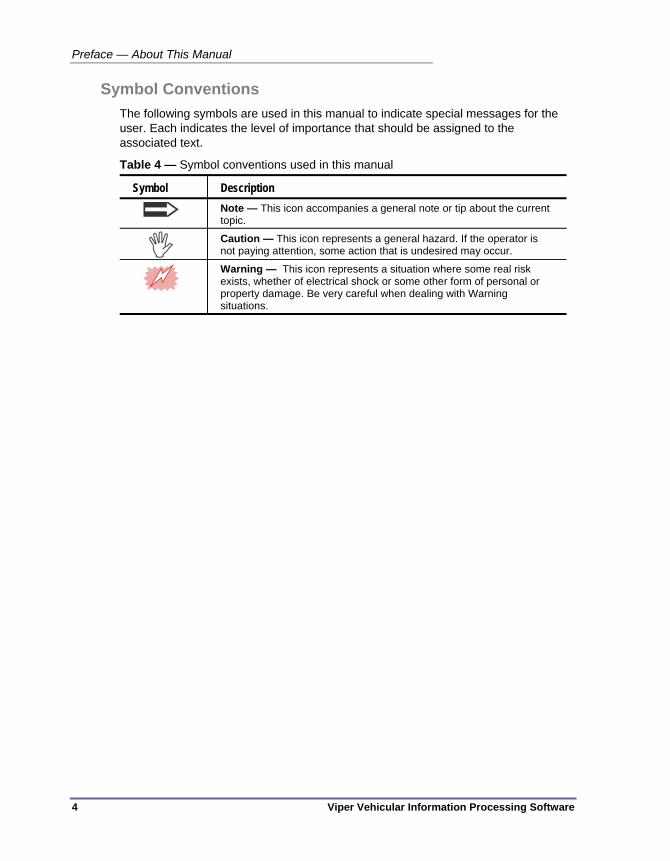
Symbol Conventions The following symbols are used in this manual to indicate special messages for the user. Each indicates the level of importance that should be assigned to the associated text.
Table 4 — Symbol conventions used in this manual
Symbol Description
Note — This icon accompanies a general note or tip about the current topic.
Caution — This icon represents a general hazard. If the operator is not paying attention, some action that is undesired may occur.
Warning — This icon represents a situation where some real risk exists, whether of electrical shock or some other form of personal or property damage. Be very careful when dealing with Warning situations.

Viper Vehicular Information Processing Software 5
Chapter 1 — Introduction to Viper
This chapter introduces the overall functionality and theory of operation of Viper. The following topics are discussed in detail in this chapter:
• An overview of the Viper strategy, on page 6.
• The typical Viper operating environment, on page 7.
• The workflow of setting up and using Viper, on page 8.
• Types of data files used by Viper, on page 9.
Chapter 1 — Introduction to Viper
6 Viper Vehicular Information Processing Software
OVERVIEW Viper is a Windows software application that is used to process the data generated by Peek’s line of automatic traffic data recorders. It follows in the tradition of earlier applications such as TOPS and TDP.
Previous data collection software from Peek has always been in the form of a user application. When computers were running DOS and unable to run concurrent applications, this was not a significant shortcoming, but operating systems like Windows removed this limitation. More recent advances (such as the widespread use of Web-based technologies) removed additional constraints. As a result, the architecture of Viper is completely different from earlier Peek software. While there is still a graphical user interface (GUI) to allow users to configure the software and perform immediate operations (such as those needed for field operations), the majority of the heavy lifting (polling, report generation, etc.) is expected to be done by Windows system services running "in the background" on one or more machines.
Using Windows Services provides several benefits:
In the event of a power outage, the service will restart automatically.
Common operations can be configured to happen automatically at times (typically overnight) when the machine is not in use for other things.
The services can be run as a specific user which has been granted permission to only the resources required. These permissions may allow access to more, or less, of the system capabilities than a given interactive user.
Important Please keep in mind that the Viper front-end interface merely provides
a configuration environment. It is not a Control environment; meaning, it is intended to configure how the server side automatic processing and scheduled task capabilities function as they run as a service in the Windows background. Aside from archiving its configuration settings and managing the available device and connection channels, the Viper interface does not have any directly-commanded interactive capabilities.

Typical Environment
Viper Vehicular Information Processing Software 7
TYPICAL ENVIRONMENT Viper is typically installed to a single PC or server in a central office, where it can use a variety of digital connection methods to communicate with a range of ADR devices in the field. Viper installs to a Windows PC (either Windows XP or Windows 7) and runs as a service in the background. The actual files of the application are installed to a Peek Traffic folder in the Program Files directory. It manages data files coming in and out of a set of folders in the Documents and Settings\All Users\Applications\Peek Traffic location on Windows XP or the ProgramFiles\Peek Traffic location on Windows 7. These install and data management folder locations are configurable during the installation and from the Viper front end interface.
Speaking of which, the Viper front end interface is the Windows application that runs on the same machine where the service operates, and is the primary configuration method for how Viper’s services operate.
There are two services that make Viper operate: the Peek State Machine Service, which performs the auto-processing functions, and the Peek Scheduler Service, which handles tasks based on time and date (namely, data polling.) The services are managed by the Windows Service infrastructure and will be restarted automatically should they or the Windows computer become unresponsive.
Data files are typically handled by Viper in a ‘pass through’ manner, meaning that they are retrieved by polling, some automatic processing is performed to move the files or change their overall format, and then the data is saved to another location with another name. The intention is to allow Viper to fit easily into a multi-application data processing environment.

Chapter 1 — Introduction to Viper
8 Viper Vehicular Information Processing Software
WORKFLOW WHEN USING VIPER The process of using Viper is pretty much analogous to the flow of chapters in this manual:
Chapter 1 – Introduction, which is what you’re reading right now.
Chapter 2 — Installation. The installation of Viper is a simple, straight-forward process as described in chapter 2. The installation of the application is a typical Windows install. The only real complications are where the user chooses to install the Viper components and setting up the communications hardware.
Chapter 3 — Using the Viper Interface. This chapter goes into detail on using the several Viper user interfaces, including the services management tools of Windows, the TOPS data import tool, and most importantly, the Viper front-end interface. Viper uses a consistent and user-friendly interface, and all of the later steps count on the user becoming familiar with these tools.
Chapter 4 — Managing Communications. After the installation, the first step to getting your Viper data management plan up and running is to configure communications ‘channels’ within Viper that are roughly analogous to your physical communications infrastructure. This chapter describes how to define and configure your communications channels.
Chapter 5 — Managing Devices. Before you can collect data from the various types of ADR hardware, you will need to set up device ‘instances’ within the Viper database. This chapter describes how to use the Viper front-end interface to do that, and how to connect each device to a communications channel, as they were set up in the previous chapter.
Chapter 6 — Setting up Auto-Processing. After the comm channels and devices are configured and connected, the next step in using Viper is to set up how it processes the data files from the ADRs. The auto-processing module is configured from within the Viper front-end interface, using an intuitive graphical programming environment.
Chapter 7 — Scheduling Activity. So after the devices, comm channels and file handling items are in place, next, we’ll need to tell Viper how to retrieve the data from the field hardware. This chapter describes how to use the Viper front-end interface to program the Peek Scheduler Service for auto-polling. After this is configured, Viper will wait until the defined dates and times, then use the defined communications channels to retrieve data from the ADRs, where it will be processed by the auto-processing plan you defined in the previous step.
Chapter 8 — Exports and Reports. This chapter is really a refinement of the auto-processing programming topic, with an emphasis on the ultimate destinations of the data. Viper can process data into either exports (reconfigured data organized for machine processing) or simple reports (reformatted data organized for human consumption.) Use these descriptions and examples to tweak your auto-processing plan.

WorkFlow when Using Viper
Viper Vehicular Information Processing Software 9
Chapter 9 — System Maintenance. Finally, the System Maintenance chapter describes how to monitor, manage and troubleshoot the Viper system on a long term basis, to keep it operating smoothly. This section provides details about global Viper system settings, activity logging, and using its features to diagnose problems. This is also the section that describes how to uninstall Viper, should you need to move it to another system, or even get rid of the software.
Types of Files used by Viper and ADRs Bin files -- These are binary files used to store the data results of studies on ADR units. This is the older, more compact of the data storage formats, and typically only includes summary information about the study itself and 'counts' of vehicles per category. It does not store information about individual vehicles, as the PVR data files do.
PVR files -- These are also binary files, but used to store a great deal more information about traffic flow. Per Vehicle Record files store details about every vehicle that passes the detection equipment. Often stored by studies configured for the more advanced detection arrays and by the Idris products. PVR files can grow very large, very quickly.
PRN files -- This is a space-delimited ASCII output file that was previously used by 241 detectors and could be read by the old TDP software package. It was originally used to send data to serial printers. Binned data can be exported to this file format, if so desired, but the PRN file format has some limitations that are more strict than some Binned data. This means that some ADR information cannot be represented in a PRN file due to the limits on the maximum number of fields and maximum permitted values that exist for certain fields in this file format.
Setup files -- These are the files that hold study configuration information in an ADR unit. When a study is configured with TOPS, it is stored to a Setup file before it is 'uploaded' to one or more ADR units. Setup files have the .stp extension.

Chapter 1 — Introduction to Viper
10 Viper Vehicular Information Processing Software

Viper Vehicular Information Processing Software 11
Chapter 2 — Installing Viper
This chapter describes how to install Viper on a server and how to get basic communications channels and devices set up. The following topics are discussed in detail in this chapter:
• An overview of the installation process, on page 12.
• The prerequisites for installing Viper, on page 12.
• The steps to install the Viper software, on page 13.
• The things that need to be done after the install, on page 14.
Chapter 2 — Installing Viper
12 Viper Vehicular Information Processing Software
OVERVIEW This chapter describes the steps to prep for a Viper install, how to perform the installation itself, and then the basics of the follow-on steps that are required to get your system up and running.
Viper can be installed on a system with very small footprint, such as a single laptop PC with a small hard drive, but a more typical installation would be on a central office Windows server that is networked and power backed up. Viper is intended as a configure and forget type of application, meaning it is supposed to sit on a PC and simply watch for incoming data. You program it to then do whatever you wish with that data, be it route the data around, sort it by type, or export or report on the results. It’s perhaps best to keep that optimal use-case in mind when configuring the hardware that will host the application.
PREPARING FOR THE INSTALL Follow this checklist to verify that you are ready to perform the Viper installation process:
Verify that the PC is running Windows NT, Windows Vista, or Windows 7. It must be running a Professional or Enterprise level version of one of these operating systems.
Make sure the operating system has all up-to-date Microsoft service packs and patches installed.
Make sure that the installer is logged in on an account that has the necessary rights to install applications and the ability to write files to the part of the hard drive where Viper will be installed.
Make sure that there is adequate hard drive space for the install. This is only approximately 20MB for the actual application, but you will need additional space for data file processing. We suggest a minimum of 2GB of free hard drive space. PVR field studies can generate very large data files, although it is true that data files themselves can be processed entirely on network drives or other outside-the-install-box locations.
You have the proper, up-to-date installation CD.

Installing Viper
Viper Vehicular Information Processing Software 13
INSTALLING VIPER Follow these steps to install the Viper package:
1. Insert the Viper Installation CD. It should show an opening screen.
2. Click once on the part of the image saying Install Viper. The installation will start by checking for prerequisites like the Crystal Report runtime libraries and install them if necessary before launching the main Viper installation.
3. After the prerequisites are installed a welcome screen, including the version number (which should be version 1.0 or later) will appear. Click Next.
4. Choose I accept the terms in the license agreement.
5. Click Next.
6. Enter user name and organization information (or accept the defaults if desired) and click Next.
7. At this point, you have three possible options:
Typical installs the most common options. The application will be installed in {Program Files}\Peek Traffic\Viper, and data files will be stored in the folder {Documents and Settings}\All Users\Application Data\Peek Traffic\Viper.
A Complete installation includes additional items not included in a Typical installation, such as command-line utilities. Like a Typical installation, the application will be installed in {Program Files}\Peek Traffic\Viper, and data files will be stored in the folder {Documents and Settings}\All Users\Application Data\Peek Traffic\Viper.
Choosing a Custom installation allows you to determine which specific modules are installed. It also allows you to select the folder where the application files are installed (by clicking the Browse button when the Core Components item is selected) and where the application data is placed (by clicking Browse when the Application Data item is selected). After you have made your selections, click Next to proceed.
8. On the Ready to install screen, click Install (or Back if you wish to change any of your selections).
9. Wait until the installation is complete, then click the Finish button.
10. After Viper is installed, you may either browse the documentation, or simply close the CD front-end by clicking on the small X in the top-right corner of the form.
11. Go to the Windows Start menu, navigate to Programs > Peek Traffic > Viper and launch the Viper application. You should see the following window after the application loads:

Chapter 2 — Installing Viper
14 Viper Vehicular Information Processing Software
Figure 1 – Verify that the Viper application has been properly installed
The appearance of this window verifies that the Viper application has been installed properly. You can now continue on and perform the next steps required to get your ADR data processing set up and running.
NEXT STEPS After the software has been successfully installed on your Windows server, you will need to complete these steps in order to bring Viper into service:
Create communications channels in Viper (Refer to “Chapter 4 — Managing Communications”, on page 29)
Create Device instances in Viper’s database (Refer to “Chapter 5 — Managing Devices” on page 51)
Define the data processing process (Refer to “Chapter 6 — Auto Processing” on page 91)
Schedule data collection events (Refer to “Chapter 7 — Scheduling Activity” on page 135)

Viper Vehicular Information Processing Software 15
Chapter 3 — Using the Viper Interface
This chapter introduces the Viper interface and explains the control elements of its various displays and dialog boxes. The following topics are discussed in detail in this chapter:
• An overview of the Viper interfaces, on page 16.
• The controls in the Viper Front End, on page 17.
• The TOPS data migration utility, on page 21.
• The Viper Network Services, on page 22.

Chapter 3 — Using the Viper Interface
16 Viper Vehicular Information Processing Software
OVERVIEW This chapter provides a description of all of the Viper interface elements in the Windows environment. Viper, at its heart, is intended to be a server-side component that functions without an interface. However, to configure and manage how its services function, Viper also provides a Windows-based application front end, as well as several other places where its operations can be manipulated within the operating system, such as the Start menu and the Services panel of the Windows Computer Management application. We will discuss how to access all of these elements, as well as the basics of how these interfaces function to manage Viper.
Figure 2 – Relationship of the Viper interfaces to operating elements
Here we will describe, in general terms, how to interact with the Front End interface, the command line utility, the TOPS data conversion utility, and the Viper server processes.

Viper Front End
Viper Vehicular Information Processing Software 17
VIPER FRONT END Most of the functions of Viper can be configured and monitored within the Viper front end interface, however this is merely a window into the operations of the core Viper application, namely the server side network services. The front end interface can be used to perform these functions:
Set up device details
Configure communications channels
Define, but NOT trigger, auto-processing
Schedule and trigger tasks for data processing, but NOT monitor the results
Define how data export will be handled by auto-processing
Define what reports will be generated by the auto-processing module
Archive and restore device, channel, and auto-processing configurations to files
With these functions in mind, the next topics describe how to launch and use the features of the Viper front end interface.

Chapter 3 — Using the Viper Interface
18 Viper Vehicular Information Processing Software
Launching the Viper Front End Application To launch Viper’s Front End user interface, click on the Start button and choose All Programs > Peek Traffic > Viper. The Viper user interface will appear, looking similar to the image shown below.
Figure 3 – Viper Front End interface start screen
The numbers shown on the image indicate the main features of the interface along with their current version details:
1. Menus — The Menus provide access to infrequently used operations (for example activating changes to the automated processing configuration).
2. Panel Address Bar — The horizontal text box and arrow button are a method to navigate between screens within the Viper Front End interface. The text shown displays the ‘address’ of the current panel selected in the Work area. The back arrow can be used to navigate to the previous screen on which the operator was last working.
3. Navigation Bar — The toolbar on the left-hand side of the form operates in a similar way to the one in Microsoft Outlook. Similar types of operations are grouped together into the same area. For example, information about all configured devices will appear in the Devices area. We refer to this area as the Navigation Bar.
4. Work Area — The large area on the right-hand side of the form will change depending on the currently selected item in the toolbar. For example, if the Systems Settings option is selected (as illustrated), the area will show information about the current data directory etc.
5. Status Bar — The status bar shows some details about the content of the current pane, such as the number of devices or channels in the list, the number of items selected, or when Viper is performing some activity, the status and type of actions that are occurring.
1
3
4
5
2

Viper Front End
Viper Vehicular Information Processing Software 19
Menus These are the Version 1.0 Front End interface menus. Menus in Viper are fixed; they do not change as you navigate around in the rest of the Viper interface, aside from some commands being grayed out when in parts of the interface where the use of those items would be illogical. For example, most of the File menu items refer to automatic processing, and are thus only available when the navigation bar has that panel selected.
Table 5 – Viper Front End interface menus
Menu Command Function New Only available from the Automatic
Processing panel. Creates a new automatic processing configuration in the Viper Front Panel interface. A new configuration opens with the standard configuration as the starting point.
Load from file Only available from the Automatic Processing panel. Instructs the Viper front end to load an auto-processing configuration from a .psm file.
Save DefaultConfiguration.psm Only available from the Automatic Processing panel. Takes the current auto-processing configuration and saves it as the default starting point for future configurations.
Save to file as Only available from the Automatic Processing panel. Stores the auto-processing plan as currently displayed in the Auto-Processing pane of Viper’s front end interface to a .psm file that can be loaded back into Viper at a later date and/or time
Get Active Automated Processing Configuration
Only available from the Automatic Processing panel. If something other than the currently running auto-processing configuration is displayed in the Front End interface’s Auto-Processing panel, this option will load the currently running process into the Front End interface.
Make currently displayed configuration active
Only available from the Automatic Processing panel. This command sends the currently displayed processing flow to the Auto-Processing service, where it will run on any new incoming data that is detected.
File
Exit Closes down the Viper Front End application. This does not interfere with the operation of the Scheduler or AutoProcessing services.
Help About Displays the Viper About panel in the Work Display area

Chapter 3 — Using the Viper Interface
20 Viper Vehicular Information Processing Software
Panel Address Bar Although the Panel Address bar may seem to be a simple and not-very-useful part of the Viper interface, in fact it has some genuine utility that grows as you gain knowledge of the interface and the parts of your data network. The address bar shows a text label that represents the current panel shown in the main Viper Work area. For instance, this address appears when viewing the About window.
Figure 4 – Panel Address Bar for the About panel
The green arrow can be used to step ‘back’ through the previous windows the operator visited during this session of the Viper Front End interface. If one is looking at a particular instance of a list within Viper, the address shows the general panel name, followed by a colon, followed by the instance name. So if we wanted to see the parameters for a device called ‘ADR3-962’, we can just type Device:ADR3-962, and the parameter screen for that device will be displayed instantly.
Figure 5 – Pulling up the data for a particular device using the address bar
Similar things can be typed to view communications channels (Channels:Com 2) and scheduled events, which are auto-numbered from oldest to newest (Scheduler:3).
TOPS Data Migration Utility
Viper Vehicular Information Processing Software 21
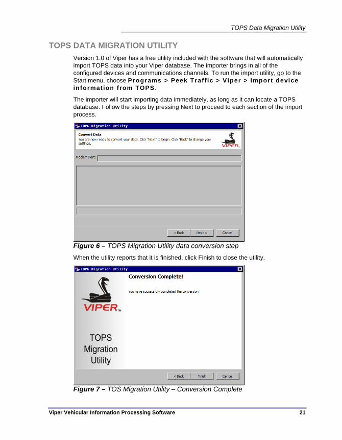
TOPS DATA MIGRATION UTILITY Version 1.0 of Viper has a free utility included with the software that will automatically import TOPS data into your Viper database. The importer brings in all of the configured devices and communications channels. To run the import utility, go to the Start menu, choose Programs > Peek Traff ic > Viper > Import device information from TOPS .
The importer will start importing data immediately, as long as it can locate a TOPS database. Follow the steps by pressing Next to proceed to each section of the import process.
Figure 6 – TOPS Migration Utility data conversion step
When the utility reports that it is finished, click Finish to close the utility.
Figure 7 – TOS Migration Utility – Conversion Complete

Chapter 3 — Using the Viper Interface
22 Viper Vehicular Information Processing Software
WINDOWS SERVICES The primary functions of Viper are performed by a pair of Windows network services. Network services have the added benefit of being managed by the operating system, so if something happens to a service, it will automatically be restarted, including after a system power outage or shutdown.
Windows services can be accessed in a couple of ways, however they are accessed only to be started, stopped, or to modify the way that they launch in some manner. The interface for Services can be found by following these steps:
1. Right-click on the My Computer icon and choose Manage. (This option will only be available for user accounts with Administrative access to the operating system.)
2. From the Computer Management application, open the Services and Applications list and click on Services.
3. Find the service names that start with ‘Peek’ in the alphabetical listing.
Figure 8 – Peek services in the Computer Management window
Services must be running in order for them to perform their functions. The Peek services are configured to start automatically and to restart whenever they are halted, whether because of a power outage, or any other reason why the computer might be restarted. Services can be Stopped, Started, or Restarted from the above environment by right-clicking on the service in question and choosing the appropriate command from its drop down menu.
Windows Services
Viper Vehicular Information Processing Software 23
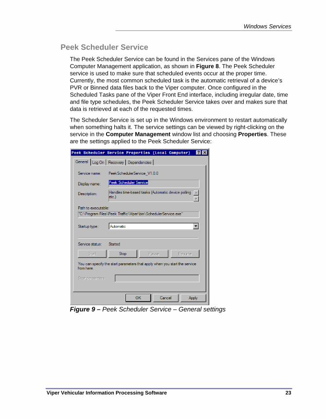
Peek Scheduler Service The Peek Scheduler Service can be found in the Services pane of the Windows Computer Management application, as shown in Figure 8. The Peek Scheduler service is used to make sure that scheduled events occur at the proper time. Currently, the most common scheduled task is the automatic retrieval of a device’s PVR or Binned data files back to the Viper computer. Once configured in the Scheduled Tasks pane of the Viper Front End interface, including irregular date, time and file type schedules, the Peek Scheduler Service takes over and makes sure that data is retrieved at each of the requested times.
The Scheduler Service is set up in the Windows environment to restart automatically when something halts it. The service settings can be viewed by right-clicking on the service in the Computer Management window list and choosing Properties. These are the settings applied to the Peek Scheduler Service:
Figure 9 – Peek Scheduler Service – General settings

Chapter 3 — Using the Viper Interface
24 Viper Vehicular Information Processing Software
Figure 10 – Peek Scheduler Service – Log On settings
Figure 11 – Peek Scheduler Service – Recovery settings

Windows Services
Viper Vehicular Information Processing Software 25
Figure 12 – Peek Scheduler Service - Dependencies
Peek Auto-Processing Service The Peek Auto-Processing Service, also known as the ‘Peek State Machine Service’, is used to perform the auto-processing flow actions. These are non-schedule based activities, meaning they are triggered by conditions other than the date and time clock of the computer. The activities triggered by the Peek State Machine service include movement and renaming of data files, processing and filtering of data, and the export and report generation based on the resulting data.
The Peek State Machine Service can be found in the Services pane of the Windows Computer Management application, as shown in Figure 8. Once a flow is configured in the Auto-Processing pane of the Viper Front End interface, the Peek State Machine Service takes over and makes sure that data is manipulated in the desired manner whenever it is detected in any of the specified auto-processing Watch folders.
Just like the Scheduler service, the Peek State Machine Service is set up in the Windows environment to restart automatically when something halts it. The service settings can be viewed by right-clicking on the service in the Computer Management window list and choosing Properties.
These are the default settings applied to the Peek State Machine Service:

Chapter 3 — Using the Viper Interface
26 Viper Vehicular Information Processing Software
Figure 13 – Peek State Machine Service – General settings
Figure 14 – Peek State Machine Service – Log On settings

Windows Services
Viper Vehicular Information Processing Software 27
Figure 15 – Peek State Machine Service – Recovery settings
Figure 16 – Peek State Machine Service – Dependencies

Chapter 3 — Using the Viper Interface
28 Viper Vehicular Information Processing Software
Viper Vehicular Information Processing Software 29
Chapter 4 — Managing Communications
This chapter introduces the Viper interface and explains the control elements of its various displays and dialog boxes. The following topics are discussed in detail in this chapter:
• An overview of device communications in Viper, on page 30.
• The available communications options in Viper, on page 30.
• Using the Communications Channels interface, on page 31.
• Adding a Channel, on page 35.
• Editing an existing Channel, on page 39.
• Deleting a Channel, on page 41.
• The available parameters for each channel type, on page 43.
• Editing Windows Routing information for IP channels, on page 48.

Chapter 4 — Managing Communications
30 Viper Vehicular Information Processing Software
OVERVIEW When first installed, Viper has no knowledge of the devices available in your system, nor the mechanism used to communicate with them. As data collection devices become more integrated into high speed networks etc., it has become more common for multiple devices to share connection information. In TOPS, this meant that you were required to re-enter that information for each device. To help simplify that, Viper introduces the concept of Connections. A connection contains information about a specific link type allowing you to specify (for example) a specific serial port and baud rate, or Dial-up IP setting. Multiple devices can then be configured to use the same connection (where applicable) without having to re-specify the common settings for each device. Another feature of Viper that can greatly aid in the setup of communications is the auto-detect feature that occurs when you first install Viper. The application will attempt to automatically detect and configure the available channels on your system. This means that many Viper users may not need to set up any communications channels at all. How is that for simple?
Available Communications Options Viper includes five possible connection types, three of which are supported by the ADR 1000, 2000 and 3000. The remaining two connection types support the ADR 6000. The connection types currently available are:
Serial connection via a physical Port - This is the traditional RS232 connection used by locally connected ADR 1/2/3000 units.
Serial connection via a modem - This is the traditional modem connection used by ADR 1/2/3000 units.
IP Network Stream - This connection type allows an ADR 1/2/3000 to be connected using an IP<->RS232 converter or wireless modem.
Permanent IP - This connection type allows communication to an ADR 6000 over a permanently available IP based network.
Dial-up IP - This connection type allows communication with an ADR 6000 over an IP based dial up connection.
To add devices, the following steps must be performed:
1. Add the connection (if an appropriate one does not exist).
2. Add the device.
Because each of the connection types and devices has slightly different characteristics, please see the specific documentation associated with the connection and/or device you are interested in.

Using the Communications Channels Panel
Viper Vehicular Information Processing Software 31
USING THE COMMUNICATIONS CHANNELS PANEL Channels within Viper are added and managed using the Communications Channels pane in the navigation panel.
Figure 17 – Comm Channels Pane – List view
Click here to see the Channels list
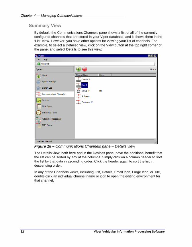
Chapter 4 — Managing Communications
32 Viper Vehicular Information Processing Software
Summary View By default, the Communications Channels pane shows a list of all of the currently configured channels that are stored in your Viper database, and it shows them in the ‘List’ view. However, you have other options for viewing your list of channels. For example, to select a Detailed view, click on the View button at the top right corner of the pane, and select Details to see this view:
Figure 18 – Communications Channels pane – Details view
The Details view, both here and in the Devices pane, have the additional benefit that the list can be sorted by any of the columns. Simply click on a column header to sort the list by that data in ascending order. Click the header again to sort the list in descending order.
In any of the Channels views, including List, Details, Small Icon, Large Icon, or Tile, double-click an individual channel name or icon to open the editing environment for that channel.

Using the Communications Channels Panel
Viper Vehicular Information Processing Software 33
The Channels - Summary View has a pair of buttons in the top left corner that allow the operator to create a new channel instance in the database and to delete one or more selected channels from the database. (Refer to Figure 30.)
Figure 19 – Add and Delete buttons in Channels-Summary panel
Simple Editing View The editing screens of Viper Communications Channels all include a Simple view and an Advanced view. Viper attempts to make it easier for most users to set up and use communications channels by only presenting the required parameters fields in most situations. If you need the ability to edit more advanced features of the channel, click on the Advanced tab.
Figure 20 – Simple editing panel for a Serial channel
Delete button — Use this button to delete the currently visible communications channel. You will be asked to verify this action.
Add a channel
Delete one or more selected channels
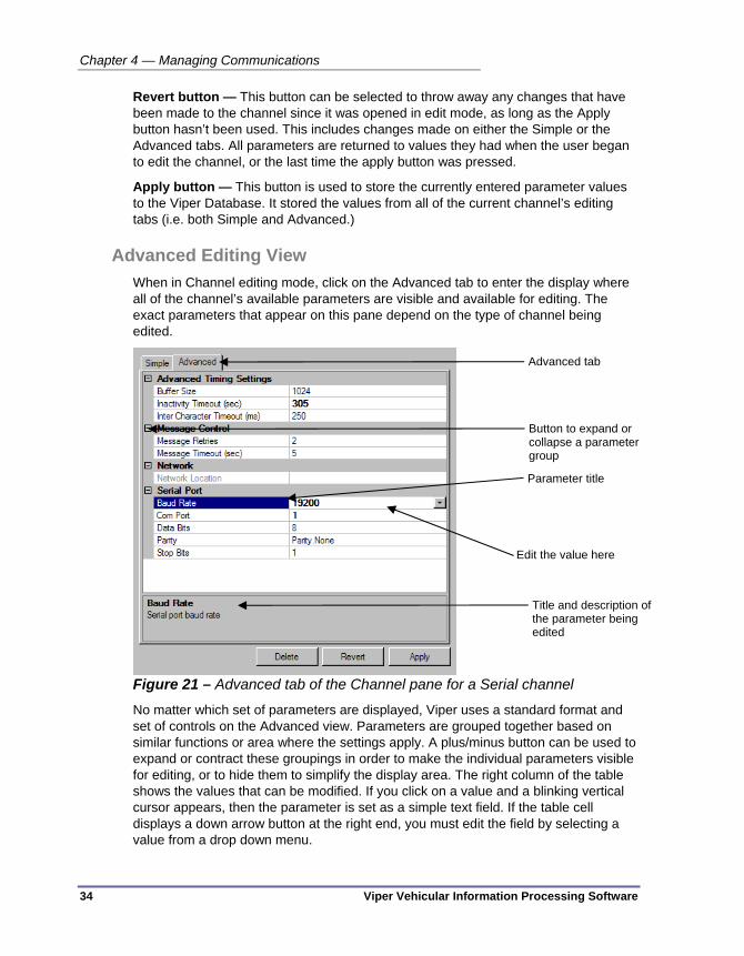
Chapter 4 — Managing Communications
34 Viper Vehicular Information Processing Software
Revert button — This button can be selected to throw away any changes that have been made to the channel since it was opened in edit mode, as long as the Apply button hasn’t been used. This includes changes made on either the Simple or the Advanced tabs. All parameters are returned to values they had when the user began to edit the channel, or the last time the apply button was pressed.
Apply button — This button is used to store the currently entered parameter values to the Viper Database. It stored the values from all of the current channel’s editing tabs (i.e. both Simple and Advanced.)
Advanced Editing View When in Channel editing mode, click on the Advanced tab to enter the display where all of the channel’s available parameters are visible and available for editing. The exact parameters that appear on this pane depend on the type of channel being edited.
Figure 21 – Advanced tab of the Channel pane for a Serial channel
No matter which set of parameters are displayed, Viper uses a standard format and set of controls on the Advanced view. Parameters are grouped together based on similar functions or area where the settings apply. A plus/minus button can be used to expand or contract these groupings in order to make the individual parameters visible for editing, or to hide them to simplify the display area. The right column of the table shows the values that can be modified. If you click on a value and a blinking vertical cursor appears, then the parameter is set as a simple text field. If the table cell displays a down arrow button at the right end, you must edit the field by selecting a value from a drop down menu.
Advanced tab
Button to expand or collapse a parameter group
Title and description of the parameter being edited
Parameter title
Edit the value here
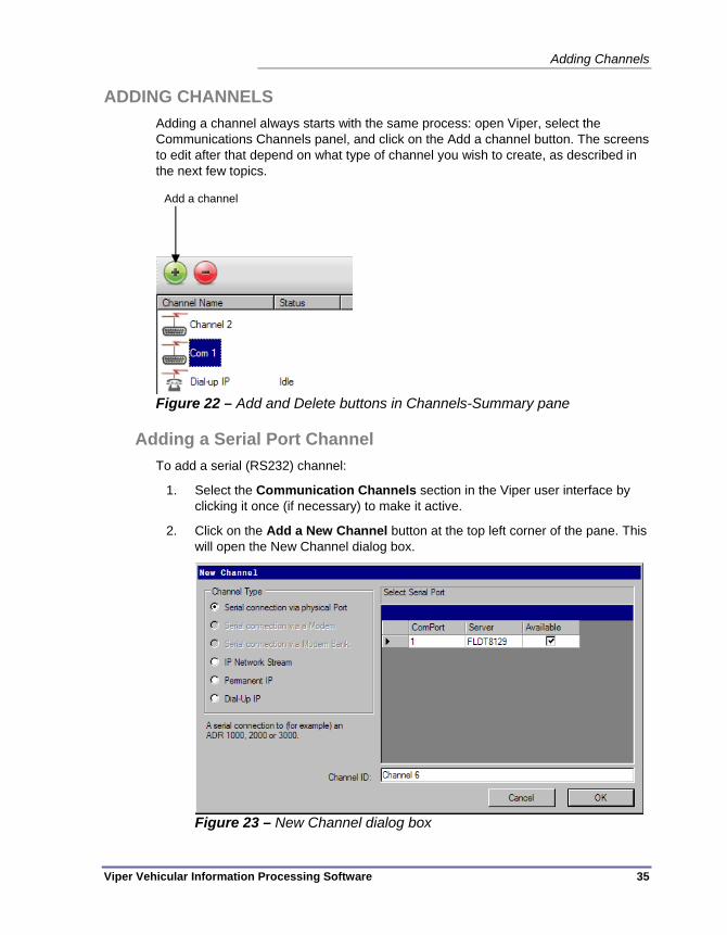
Adding Channels
Viper Vehicular Information Processing Software 35
ADDING CHANNELS Adding a channel always starts with the same process: open Viper, select the Communications Channels panel, and click on the Add a channel button. The screens to edit after that depend on what type of channel you wish to create, as described in the next few topics.
Figure 22 – Add and Delete buttons in Channels-Summary pane
Adding a Serial Port Channel To add a serial (RS232) channel:
1. Select the Communication Channels section in the Viper user interface by clicking it once (if necessary) to make it active.
2. Click on the Add a New Channel button at the top left corner of the pane. This will open the New Channel dialog box.
Figure 23 – New Channel dialog box
Add a channel

Chapter 4 — Managing Communications
36 Viper Vehicular Information Processing Software
3. Select Serial connection via physical Port as the channel type.
4. In the box to the right, select the specific port you want to use. This box is automatically populated with all of the serial ports that Windows detects on your hardware.
5. [Optional] Change the Channel ID to something which uniquely identifies the channel (for example Com1 at 19200). This is the text that will appear as the channel name in the Channel Summary list and which you will select when editing a Device’s connection value.
6. Click OK to add the channel.
Adding a Modem Channel To add a modem based channel to Viper, follow these steps:
1. Select the Communication Channels section in the Viper user interface by clicking it once (if necessary) to make it active.
2. Click on the Add a New Channel button at the top left corner of the pane. This will open the New Channel dialog box. (The New Channel dialog box is shown in Figure 23 on page 35.)
3. Select Serial connection via a Modem as the channel type. (If no modems have been configured in Windows, this option will be grayed out and unavailable. To set up the modem channel, you will need to go out to the Windows environment and set it up there before coming back into Viper and performing this step.) Please note that if you add a modem to Windows, you will need to restart the Viper front end interface in order to make the new modem show up in the available New Channel options.
4. In the box at the right, select the modem you wish to use. This table is automatically populated with all of the modems currently configured in Windows.
5. [Optional] Change the Channel ID to something which uniquely identifies the channel (for example Modem on Com1). This is the text that will appear as the channel name in the Channel Summary list and which you will select when editing a Device’s connection value.
6. Click OK to add the channel.
Adding a Serial Modem Bank Channel In Version 1.0 of Viper, the Serial Modem bank option is not yet supported.

Adding Channels
Viper Vehicular Information Processing Software 37
Adding an IP Network Stream Channel An IP network stream can be set up if you plan to connect to an ADR 1000, ADR-2000 or ADR-3000 device over Ethernet by going through an IP to RS232 converter or via a wireless modem attached to the device’s serial port. To add an IP stream based channel to Viper, do the following:
1. Select the Communication Channels section in the Viper user interface by clicking it once (if necessary) to make it active.
2. Click on the Add a New Channel button at the top left corner of the pane. This will open the New Channel dialog box. (The New Channel dialog box is shown in Figure 23 on page 35.)
3. Select IP Network Stream as the channel type.
4. [Optional] Change the Channel ID to something which uniquely identifies the channel (for example 192.168.1.2 on port 80).This is the text that will appear as the channel name in the Channel Summary list and which you will select when editing a Device’s connection value. Note that this value will be overridden by the device-specific IP settings when the channel is applied to the device, so these values are largely placeholders.
5. Click OK to add the channel.
6. Click Apply to save the changes.
Adding a Permanent IP Channel A Permanent IP channel does not specify a particular IP address; you set that value in each Device. And all of the devices that use a fixed IP address can use the same single ‘Permanent IP’ channel within Viper. To add that permanently-available IP based channel to Viper, follow these steps:
1. Select the Communication Channels section in the Viper user interface by clicking it once (if necessary) to make it active.
2. Click on the Add a New Channel button at the top left corner of the pane. This will open the New Channel dialog box. (The New Channel dialog box is shown in Figure 23 on page 35.)
3. Select Permanent IP as the channel type.
4. [Optional] Change the Channel ID to something which uniquely identifies the channel (for example Permanent IP Channel). This is the text that will appear as the channel name in the Channel Summary list and which you will select when editing a Device’s connection value.
5. Click OK to add the channel.

Chapter 4 — Managing Communications
38 Viper Vehicular Information Processing Software
Adding a Dial-Up IP channel To create a dial-up Ethernet connection (using PPP) in Viper, follow these steps:
1. Select the Communication Channels section in the Viper user interface by clicking it once (if necessary) to make it active.
2. Click on the Add a New Channel button at the top left corner of the pane. This will open the New Channel dialog box. (The New Channel dialog box is shown in Figure 23 on page 35.)
3. Select Dial-Up IP as the channel type.
4. From the table at the right side of the dialog box, select the Windows PPP IP connection to use. If no PPP connection has been configured in Windows, contact your system administrator to set that channel up in your operating system.
5. [Optional] Change the Channel ID to something which uniquely identifies the channel (for example ADR 6000 Dial Up). This is the text that will appear as the channel name in the Channel Summary list and which you will select when editing a Device’s connection value.
6. Click OK to add the channel.
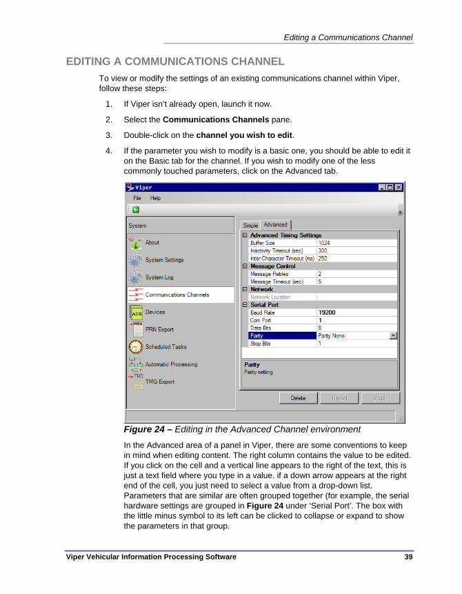
Editing a Communications Channel
Viper Vehicular Information Processing Software 39
EDITING A COMMUNICATIONS CHANNEL To view or modify the settings of an existing communications channel within Viper, follow these steps:
1. If Viper isn’t already open, launch it now.
2. Select the Communications Channels pane.
3. Double-click on the channel you wish to edit.
4. If the parameter you wish to modify is a basic one, you should be able to edit it on the Basic tab for the channel. If you wish to modify one of the less commonly touched parameters, click on the Advanced tab.
Figure 24 – Editing in the Advanced Channel environment
In the Advanced area of a panel in Viper, there are some conventions to keep in mind when editing content. The right column contains the value to be edited. If you click on the cell and a vertical line appears to the right of the text, this is just a text field where you type in a value. if a down arrow appears at the right end of the cell, you just need to select a value from a drop-down list. Parameters that are similar are often grouped together (for example, the serial hardware settings are grouped in Figure 24 under ‘Serial Port’. The box with the little minus symbol to its left can be clicked to collapse or expand to show the parameters in that group.

Chapter 4 — Managing Communications
40 Viper Vehicular Information Processing Software
5. Whether editing on the Basic or Advanced tab, when you are finished making changes, be sure to click the Apply button to save the changes to the Viper database.
6. To return to the main list of available Communications Channels, click on the Communications Channels row in the navigation list on the left side of the Viper window.

Deleting a Communications Channel
Viper Vehicular Information Processing Software 41
DELETING A COMMUNICATIONS CHANNEL To delete a channel from the Communications Channels list, follow this procedure:
Note Deleting a channel cannot be undone unless you have an archive
copy of the system that includes that channel. And keep in mind that restoring an archive will also remove any configuration changes that were made since the archive was created. For channels, it’s often easier to re-create the channel from scratch than to restore it after inadvertently deleting one, especially if the channel used mostly default settings.
1. Go to System Settings and select Archive (This creates a backup of your system, including the channel or channels you are about to delete.)
2. Go to the Communications Channels – Summary view
Figure 25 – Comms Channels:Summary view with one channel selected
3. Select the channel or channels that you wish to delete. (Ctrl-click to choose more than one channel, or click-drag the mouse to select multiple channels that are near one another.)
4. Click on the Delete button to remove the selected channel(s).
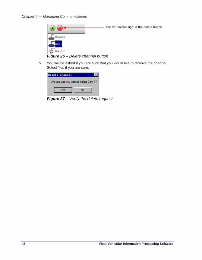
Chapter 4 — Managing Communications
42 Viper Vehicular Information Processing Software
Figure 26 – Delete channel button
5. You will be asked if you are sure that you would like to remove the channel. Select Yes if you are sure.
Figure 27 – Verify the delete request
The red ‘minus sign’ is the delete button

Channel Parameters
Viper Vehicular Information Processing Software 43
CHANNEL PARAMETERS These are detailed descriptions of each of the parameters for each of the channel types that are available in Viper.
Serial Channel via a Physical Port
Advanced Timing Settings Buffer Size — The amount of PC memory to use to hold flowing data to and from the serial port. The buffer helps smooth out traffic flow when data may flow at an uneven rate over the serial connection. Size is in bytes. The default value is 1kB (1024 bytes).
Inactivity Timeout — This tells Viper how long to maintain an open connection channel if no activity is being seen on the port. The number is in seconds and the default value is 300. (5 minutes)
Inter Character Timeout — A value in milliseconds that indicates how long Viper will wait between bytes of data within a single packet before requesting a re-transmission. The default value is 250ms, or a quarter of a second.
Message Control Parameters Message Retries — When a request for information fails, Viper automatically asks for the information again. This number indicates how many times Viper should request the message before moving on to the next parameter. The default value is 2 retries. (a total of 3 attempts per data point)
Message Timeout — The period of time, in seconds, that you want Viper to wait for a response after requesting information from the device. The default value is 5 seconds.
Network Parameters Network Location — The name of the computer where this communication channel resides. Not currently used.
Serial Port Parameters Baud Rate — The data transmission speed to use across this serial port. Most of the ADR devices can support any of the available speeds listed in the drop-down box. The baud rate to use is more often determined by the hardware connecting the PC to the modem, including the baud rate defined for the port, the quality and length of the connection between the PC and the device, and the hardware being used to connect the channel to the serial port on the ADR.
Com Port — The COM port you wish to use on this PC. This is the label used by the operating system to identify the physical port on the back of your computer.
Data Bits — The length of a byte in the serial port transmission. It can be either 7 or 8 bits per byte. The typical, and most common, setting is 8 bit.

Chapter 4 — Managing Communications
44 Viper Vehicular Information Processing Software
Parity — A simple method of error detection for serial communications in which a bit is used to add either a 0 or 1 to a byte so that the total byte has either an even or an odd number of 1s. Typically set to ‘None’.
Stop Bits — In asynchronous serial communications, a number of bits are used to indicate the end of a byte. The number of stop bits is typically set to 1.
Serial Channel via a Modem
Advanced Timing Settings Buffer Size — The amount of PC memory to use to hold flowing data to and from the serial port. The buffer helps smooth out traffic flow when data may flow at an uneven rate over the serial connection. Size is in bytes. The default value is 1kB (1024 bytes).
Dialup Timeout — The amount of time (in seconds) to wait for the modem at the other end of the connection to pick up the call. If this time elapses without a pickup, Viper will stop trying to establish the connection.
Inactivity Timeout — This tells Viper how long to maintain an open connection channel if no activity is being seen on the port. The number is in seconds and the default value is 300. (5 minutes)
Inter Character Timeout — A value in milliseconds that indicates how long Viper will wait between bytes of data within a single packet before requesting a re-transmission. The default value is 250ms, or a quarter of a second.
Modem Response Timeout — This is the amount of time (in milliseconds) that Viper will spend attempting to initialize the modem attached to this PC. If the local modem does not respond in this timeframe, Viper will stop attempting to establish the connection. The default value is 3000ms, or 3 seconds.
Pause After Connect — The time, in milliseconds, that Viper will wait after the phone connection is established, before it will attempt to transmit data over the channel. The default value is 1000ms (1 second).
Pause After Disconnect — The time, in milliseconds, that Viper will wait after closing a dialup serial connection (meaning that the modem has hung up the call), before attempting to use the modem to establish any new connection. This is to allow for the case where a phone system may be slow to respond to the hang up, and thus preventing Viper from inadvertently reusing the old open line to establish some new connection, with uncertain results. The default value is 1000ms (1 second).
Initialization String Settings Additional Settings — If you need to add any additional text commands to the modem initialization string, this is where you can type them. These commands are added to the AT string between the ATD (or ATDT) command and the phone number.
Channel Parameters
Viper Vehicular Information Processing Software 45
Auto Answer Off String — The piece of text that will be added to the command strings sent to the modem to turn OFF its Auto Answer feature. The default value is “S0=0”.
Auto Answer On String — The piece of text that will be added to the command strings sent to the modem to turn ON its Auto Answer feature. The default value is “S0=1”.
Echo Off String — The piece of text that will be added to the command strings sent to the modem to turn OFF the modem’s Echo feature. The echo feature, when active, causes the modem to provide textual feedback along the data stream, indicating status information. These messages have the potential to interfere with the way that Viper reads the data. The default Echo OFF string is “E0”, however some modems may use a different Echo OFF command.
Verbose Result Codes String — This piece of text will be added to the command strings sent to the modem to instruction the modem to provide verbose result codes. The default string is “V1X4”.
Message Control Settings Message Retries — When a request for information fails, Viper automatically asks for the information again. This number indicates how many times Viper should request the message before moving on to the next parameter. The default value is 2 retries. (a total of 3 attempts per data point)
Message Timeout — The period of time, in seconds, that you want Viper to wait for a response after requesting information from the device. The default value is 5 seconds.
Monitor Mode Settings Monitor Mode — Instructs the modem to wait for incoming phone calls from the device. This feature is turned OFF by default, since most ADR configurations are not able to generate autonomous attempts to call the Viper server.
Network Settings Network Location — The name of the computer where this communication channel resides. Not currently used.
Serial Port Settings Baud Rate — The data transmission speed to use on the serial port that is connected to the local modem. Most of the ADR devices can support any of the available speeds listed in the drop-down box. The baud rate to use is more often determined by the hardware connecting the PC to the modem, including the baud rate defined for the port, the quality and length of the lines between the modem and the device, the modem at the other end. The default speed is 115,200.

Chapter 4 — Managing Communications
46 Viper Vehicular Information Processing Software
Com Port — The COM port you wish to use on this PC. This is the label used by the operating system to identify the physical port on the back of your computer.
Data Bits — The length of a byte in the serial port transmission. It can be either 7 or 8 bits per byte. The typical, and most common, setting is 8 bit.
Parity — A simple method of error detection for serial communications in which a bit is used to add either a 0 or 1 to a byte so that the total byte has either an even or an odd number of 1s. Typically set to ‘None’.
Stop Bits — In asynchronous serial communications, a number of bits are used to indicate the end of a byte. The number of stop bits is typically set to 1.
Serial Channel via a Modem Bank This option is not available in Viper v1.0, so there are no associated parameters at this time.
IP Network Stream
Address Settings Description — An additional description of this communication channel. Not currently used.
Host — The IP address or host name that Viper can use to connect to a device across an Ethernet network. Use of a host name requires that the device be registered with a DNS server. The Host name tests to see if an IP address can be retrieved for the specified name and whether or not a valid network node responds from the resulting address. This test does not attempt to verify that the device is actually an ADR.
IP Port — This is an integer value between 0 and 65535 that indicates which TCP port on the target device should be used to try to access the device. If the IP address is the building address for a device, the port can be thought of as a room number within that building. Port numbers often come into play when configuring the channel for a firewall, or for networks that encourage communications to occur on specific ports for security or data management reasons. The default port is ‘10001’.
Advanced Settings Receive Buffer Size — The amount of memory used to temporarily store outgoing data in readiness to be sent out over the channel. The default value is 8192 bytes (8K).
Receive Timeout — The amount of time (in milliseconds) that Viper should wait each time it begins receiving a data packet. If the timeout is exceeded, Viper will request the information again. The default value is 10000 (10 seconds).

Channel Parameters
Viper Vehicular Information Processing Software 47
Send Buffer Size — The amount of memory used to temporarily store incoming data (coming into this PC across this communications channel) in readiness to be read by the Viper service. The default value is 8192 bytes (8K).
Send Timeout — The time in milliseconds that Viper should allow for the data to be sent. The default value is 10000 (10 seconds).
Permanent IP Channel There are no configurable parameters for a Permanent IP Channel. The IP address and host settings for this channel are set on a device-by-device basis in the Device > Connection panel.
Dial-Up IP Channel
Miscellaneous Settings DelayAfterClose — The time, in milliseconds, that Viper will wait after closing a dialup IP connection (meaning that the modem has hung up the call), before attempting to use the modem to establish any new connection. This is to allow for the case where a phone system may be slow to respond to the hangup, and thus preventing Viper from inadvertently reusing the old open line to establish some new connection, with uncertain results. The default value is 1000ms (1 second).
Description — An additional description of this communication channel. Not currently used.

Chapter 4 — Managing Communications
48 Viper Vehicular Information Processing Software
CONFIGURING IP ROUTING If you are talking to a device (such as the ADR 6000) which can use IP based communication you may need to explicitly configure the mechanism Windows uses to route the messages. This is especially true if you are using dial-up networking, or have more than one network card in your machine.
Why are Route rules necessary? Routing rules are necessary in some cases because otherwise Windows would not know how to reach a specific IP address. IP Routing is beyond the scope of this document, but in some ways it works a little like the postal service. IP addresses belong to a network, which could be thought of like the city in a postal address. If you only wrote Customer Support, 2906 Corporate Way on an envelope there is the chance that it could not be delivered at all, or worse it could easily be delivered to the wrong person. By specifying Palmetto, Florida, the message is first routed to the Palmetto post office, then delivered from there. An IP routing rule provides a similar function. It effectively says: For addresses in the specified range, start by sending the message to a certain initial IP address, also known as a gateway.
The ROUTE command Included as part of the operating system is the command line route utility. More details about the route command can be found on the Microsoft Documentation Website [1]. This command allows you to display and edit current routing information.
There are two types of routing rule - temporary and permanent. As you would expect, a temporary route is lost whenever the machine is restarted (or if using a dial-up network connection when the network connection is lost), while a permanent one is preserved.
Adding a routing rule for a dial- up unit For an ADR 6000 connected using dial-up networking, the default dial-up IP address will be 192.168.2.1 with a netmask of 255.255.255.0. When the dial-up connection to the unit is established, the PC side of the connection will be assigned the IP address 192.168.2.2 and a netmask the same as the ADR 6000.
In addition to the IP address associated with the dial-up connection, the ADR 6000 also has a permanent address. The default value for the permanent address is 192.168.5.1, but that value may be modified (for example if the ADR 6000 is chained to other devices). Typically, chained devices will have an address where the first three numbers match, but the fourth is different.
Without an explicitly configured route, any attempt to contact an ADR 6000 using its permanent address will not use the dial-up IP connection. Instead the PC will attempt to access the ADR 6000 using the default gateway for the system (typically your network card).

Configuring IP Routing
Viper Vehicular Information Processing Software 49
To tell the PC that you wish to create a rule that communications to anything with an address in the range 192.168.5.x must go through the dial-up connection you need to perform the following steps:
1. Establish the dial-up connection to the ADR 6000.
2. Click the Start button and select Run.
3. Type cmd and hit the enter button or click OK.
4. At the command prompt, type route add 192.168.5.0 mask 255.255.255.0 192.168.2.2.
5. Verify that you can contact the ADR 6000 (e.g. by opening it's web page, or using ping or tracert).
Making a routing rule permanent Once you are sure that the routing rule is correct, you will typically want to make it permanent. You do so by adding -p as the second parameter in the route command line. For example, the temporary route configured above could be made permanent by typing route –p add 192.168.5.0 mask 255.255.255.0 192.168.2.2 instead.
Note When adding routes associated with dial-up connections, the route must be added while the connection is active. If the route is not made permanent, then it will be lost when the connection is terminated.
Routing rules for permanently connected devices Consider the following scenario: You have an ADR 6000 (with the IP address of 192.168.5.1, and netmask of 255.255.255.0) attached to a secondary network card in your system. (Let's say that the IP address for the secondary network card is 192.168.5.100, and the netmask is the same as the ADR 6000.) Without an explicitly configured route, any attempt to contact the ADR 6000 will not, as you might expect, use the secondary network card. Instead the PC will attempt to access the ADR 6000 using the default gateway for the system.
To tell the PC that you wish to create a permanent rule that communications to anything with an address in the range 192.168.5.x to go through your secondary network card you need to perform the following steps:
1. Click the Start button and select Run.
2. Type cmd and hit the enter button or click OK.
3. At the command prompt, type route add 192.168.5.0 mask 255.255.255.0 192.168.5.100.
4. Verify that you can contact the ADR 6000 (e.g. by opening it's web page, or using ping or tracert).
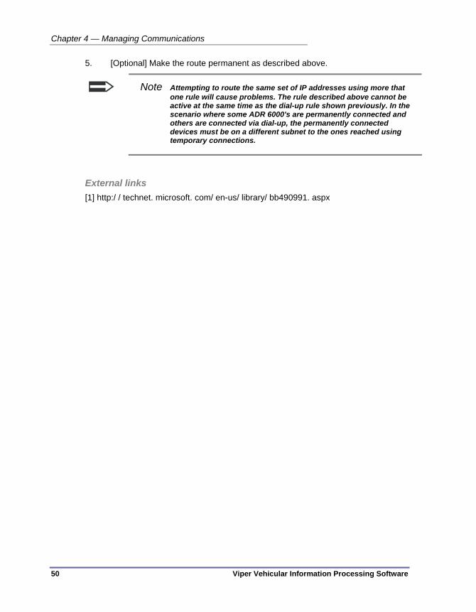
Chapter 4 — Managing Communications
50 Viper Vehicular Information Processing Software
5. [Optional] Make the route permanent as described above.
Note Attempting to route the same set of IP addresses using more that one rule will cause problems. The rule described above cannot be active at the same time as the dial-up rule shown previously. In the scenario where some ADR 6000's are permanently connected and others are connected via dial-up, the permanently connected devices must be on a different subnet to the ones reached using temporary connections.
External links [1] http:/ / technet. microsoft. com/ en-us/ library/ bb490991. aspx

Viper Vehicular Information Processing Software 51
Chapter 5 — Managing Devices
This chapter discusses how to create devices in the Viper database and how to manage your list of available devices. The following topics are discussed in detail in this chapter:
• An overview of device management in Viper, on page 52.
• An introduction to the Devices interface, on page 53.
• How to Add a device to Viper, on page 57.
• How to Edit a device, on page 61.
• How to Delete a device instance in Viper, on page 62.
• A complete Device properties listing, on page 64.

Chapter 5 — Managing Devices
52 Viper Vehicular Information Processing Software
OVERVIEW Currently, Viper can retrieve and work with data from two classes of devices:
Peek ADR Devices:
ADR-1000 and ADR-1000 Plus
ADR-2000 and ADR-2000 Plus
ADR-3000 and ADR-3000 Plus
Peek ADR-6000 Devices
Before one can connect with and retrieve data from any of these devices, Viper needs to know some information and configuration details about the hardware and how it should connect to the hardware. Connection to the hardware is largely discussed in “Chapter 4 — Managing Communications”, which starts on page 29.
Whether to set up your devices first or communications channels first is a matter of individual preference, although it is important to keep in mind that the communications channel to be used by a device must be configured already before you can configure a device to use that channel. Usually, we recommend that a comms channel be set up first, and then the operator can create and assign the device to that channel in one step. Others like to start with the devices first, then create the comms channel, and finally go back into the device configuration and attach the channel to the device. Either method will work.
One important suggestion to consider before you start creating devices in Viper is to make sure that you have some systematic method to label and identify your vehicle counting and classification hardware. Having unique names that match a label on the device, the configuration of the device, and the device instance within Viper, is the first step to creating a logical, easily-maintained traffic data management system.

Using the Devices Pane
Viper Vehicular Information Processing Software 53
USING THE DEVICES PANE Devices within Viper are added and managed using the Devices pane in the navigation panel.
Figure 28 – Devices Pane – List view
Summary View By default, the Devices pane shows a list of all of the currently configured devices that are stored in your Viper database, and it shows them in the ‘List’ view. However, you have other options for viewing your list of devices. For example, to select a Detailed view, click on the View button at the top right corner of the Devices pane, and select Details to see this view:
Click here to see the Devices list

Chapter 5 — Managing Devices
54 Viper Vehicular Information Processing Software
Figure 29 – Devices Pane – Details view
The Details view, both here in the Devices pane and in the Communications Channels pane, have the additional benefit that the list can be sorted by any of the columns. Simply click on a column header to sort the list by that data in ascending order. Click the header again to sort the list in descending order.
Every version of the Devices- Summary View has a pair of buttons in the top left corner that allow the operator to create a new device instance in the database and to delete one or more selected devices from the database. (Refer to Figure 30.)
Figure 30 – Add and Delete buttons in Device-Summary pane
Add a device
Delete one or more selected devices
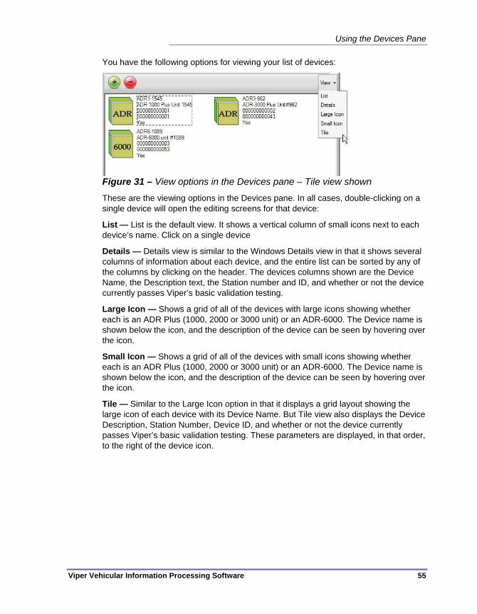
Using the Devices Pane
Viper Vehicular Information Processing Software 55
You have the following options for viewing your list of devices:
Figure 31 – View options in the Devices pane – Tile view shown
These are the viewing options in the Devices pane. In all cases, double-clicking on a single device will open the editing screens for that device:
List — List is the default view. It shows a vertical column of small icons next to each device’s name. Click on a single device
Details — Details view is similar to the Windows Details view in that it shows several columns of information about each device, and the entire list can be sorted by any of the columns by clicking on the header. The devices columns shown are the Device Name, the Description text, the Station number and ID, and whether or not the device currently passes Viper’s basic validation testing.
Large Icon — Shows a grid of all of the devices with large icons showing whether each is an ADR Plus (1000, 2000 or 3000 unit) or an ADR-6000. The Device name is shown below the icon, and the description of the device can be seen by hovering over the icon.
Small Icon — Shows a grid of all of the devices with small icons showing whether each is an ADR Plus (1000, 2000 or 3000 unit) or an ADR-6000. The Device name is shown below the icon, and the description of the device can be seen by hovering over the icon.
Tile — Similar to the Large Icon option in that it displays a grid layout showing the large icon of each device with its Device Name. But Tile view also displays the Device Description, Station Number, Device ID, and whether or not the device currently passes Viper’s basic validation testing. These parameters are displayed, in that order, to the right of the device icon.
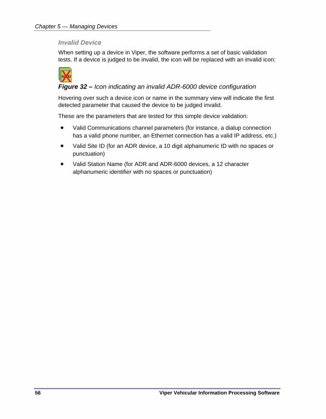
Chapter 5 — Managing Devices
56 Viper Vehicular Information Processing Software
Invalid Device When setting up a device in Viper, the software performs a set of basic validation tests. If a device is judged to be invalid, the icon will be replaced with an invalid icon:
Figure 32 – Icon indicating an invalid ADR-6000 device configuration
Hovering over such a device icon or name in the summary view will indicate the first detected parameter that caused the device to be judged invalid.
These are the parameters that are tested for this simple device validation:
Valid Communications channel parameters (for instance, a dialup connection has a valid phone number, an Ethernet connection has a valid IP address, etc.)
Valid Site ID (for an ADR device, a 10 digit alphanumeric ID with no spaces or punctuation)
Valid Station Name (for ADR and ADR-6000 devices, a 12 character alphanumeric identifier with no spaces or punctuation)
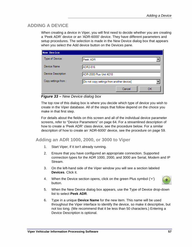
Adding a Device
Viper Vehicular Information Processing Software 57
ADDING A DEVICE When creating a device in Viper, you will first need to decide whether you are creating a ‘Peek ADR’ device or an ‘ADR-6000’ device. They have different parameters and setup procedures. The selection is made in the New Device dialog box that appears when you select the Add device button on the Devices pane.
Figure 33 – New Device dialog box
The top row of this dialog box is where you decide which type of device you wish to create in the Viper database. All of the steps that follow depend on the choice you make in that first step.
For details about the fields on this screen and all of the individual device parameter screens, refer to “Device Parameters” on page 64. For a streamlined description of how to create a ‘Peek ADR’ class device, see the procedure below. For a similar description of how to create an ‘ADR-6000’ device, see the procedure on page 59.
Adding an ADR 1000, 2000, or 3000 to Viper 1. Start Viper, if it isn’t already running.
2. Ensure that you have configured an appropriate connection. Supported connection types for the ADR 1000, 2000, and 3000 are Serial, Modem and IP Stream.
3. On the left-hand side of the Viper window you will see a section labeled Devices. Click it.
4. When the Device section opens, click on the green Plus symbol (‘+’) button.
5. When the New Device dialog box appears, use the Type of Device drop-down list to select Peek ADR.
6. Type in a unique Device Name for the new item. This name will be used throughout the Viper interface to identify the device, so make it descriptive, but not too long. (We recommend that it be less than 50 characters.) Entering a Device Description is optional.
Chapter 5 — Managing Devices
58 Viper Vehicular Information Processing Software
7. If there is another device in your system that has a configuration that is similar to the one you plan to create for this device, select that device from the Copy settings from drop-down box, and all of the current settings for that other device will be copied into this new device’s fields.
8. Click OK to continue past the New Devices dialog box. The main parameter tabs for the new device will appear.
9. Go to the Connection tab.
10. Make sure that the Channel is correct (If there is only one channel which supports the ADR 1/2/3000, then Viper should select it automatically). If not correct, configure the communications channel as required for this unit by filling in the fields on this tab.
11. Click on the Site tab.
12. In the Site ID field, enter the correct value. (The Site ID for an ADR unit is the unique 12 digit alphanumeric value that is set within the hardware.)
13. Similarly, make sure the Station Number is set to match the station number programmed into the ADR unit.
14. On this same tab, make sure that the Number of arrays field has the appropriate value for this device and test location. After entering the number of arrays, assign each channel to a direction or lane assignment.
15. Click Apply to save the values you’ve entered.
16. At this point, the minimum requirements have been met to establish a connection between Viper and the hardware. Make sure the cabling or modem that will be used with the device is properly installed at both the PC and the ADR ends.
17. If you are configuring an ADR-6000, go to the Operations tab. From here you can either load a configuration from a file, or retrieve the current configuration from the device. (These options do not work with the other ADR types in the version 1.0 release of Viper.)
18. As a last check on the setup, press the Check Device Date and Time button. This will indicate whether or not you have a good setup and connection to the device. If you cannot successfully check the date and time on the device, you will need to double check your settings and your connection cabling/hardware to make sure everything is correct.
At this point, the hardware is connected to Viper. You can use the other tabs and fields of the Devices pane to provide more description of the ADR station, to configure studies and reporting requirements, and generally to manage the station. Details about all of the fields on this pane are described beginning on page 64.

Adding a Device
Viper Vehicular Information Processing Software 59
Adding an ADR 6000 to Viper 1. Start Viper, if it isn’t already running.
2. Ensure that you have configured an appropriate connection for this device. Supported connection types for the ADR 6000 running firmware 6.3.33 or later are permanent IP and dial-up IP.
3. On the left-hand side of the Viper window you will see a section labeled Devices. Click it.
4. When the Device section opens, click on the green Plus symbol (‘+’) button.
5. When the New Device dialog box appears, use the Type of Device drop-down list to select ADR 6000.
6. Type in a unique Device Name for the new item. This name will be used throughout the Viper interface to identify the device, so make it descriptive, but not too long. (We recommend that it be less than 50 characters.) Entering a Device Description is optional.
7. If there is another device in your system that has a configuration that is similar to the one you plan to create for this device, select that device from the Copy settings from drop-down box, and all of the current settings for that other device will be copied into this new device’s fields.
8. Click OK to continue past the New Devices dialog box. The main parameter tabs for the new device will appear.
9. Go to the Connection tab.
10. Make sure that the Channel is correct (If there is only one channel which supports an ADR 6000, then Viper should select it automatically). If not correct, configure the communications channel as required for this unit by filling in the fields on this tab.
11. There are two ways to point the channel to your specific device, by IP address or by device name:
By IP Address:
a.) Select the IP Address radio button.
b.) Type the device's IP address (for example: 192.168.5.1) into the text box.
By device name:
a.) Select the Host Name radio button.
b.) Enter the device name in the text box. (Use of a host name assumes that there is a Dynamic Name Server (DNS) visible to the PC and that the DNS

Chapter 5 — Managing Devices
60 Viper Vehicular Information Processing Software
has this host name associated with the correct IP address, or there is an IP address defined in the PC’s “Hosts” file.)
c.) [Optional] Click the Check Host Name button to ensure that an IP address can be located for a device with the name given.
12. Having chosen a specific device, the correct user name and password must also be supplied. In the User Name field, enter the name of the user configured on the ADR 6000. (The factory default user for devices with version 6.3.33 firmware is Peek.)
13. In the Password field enter the password for that user. (The factory default password for devices with ADR 6000 version 6.3.33 firmware is TrafficData.)
14. Click on the Site tab.
15. In the Site ID field, enter the correct value. (The Site ID for an ADR unit is the unique 12 digit alphanumeric value that is set within the hardware.)
16. Similarly, make sure the Station Number is set to match the station number programmed into the ADR unit.
17. On this same tab, make sure that the Number of arrays field has the appropriate value for this device and test location. After entering the number of arrays, assign each channel to a direction or lane assignment.
18. Click Apply to save the values you’ve entered.
19. At this point, the minimum requirements have been met to establish a connection between Viper and the hardware. Make sure the cabling that will be used with the device is properly installed at both the PC and the ADR ends.
20. Go to the Operations tab. From here you can either load a configuration from a file, or retrieve the current configuration from the device.
21. As a last check on the setup, press the Check Device Date and Time button. This will indicate whether or not you have a good setup and connection to the device. If you cannot successfully check the date and time on the device, you will need to double check your settings and your connection cabling/hardware to make sure everything is correct.
At this point, the hardware is connected to Viper. You can use the other tabs and fields of the Devices pane to provide more description of the ADR station, to configure studies and reporting requirements, and generally to manage the station. Details about all of the fields on this pane are described beginning on page 64.

Editing a Device
Viper Vehicular Information Processing Software 61
EDITING A DEVICE To view or modify the parameters for a device that already exists in your Viper Device list, follow these steps:
1. If Viper isn’t already open, launch it now.
2. Select the Device pane.
3. Double-click on the device you wish to edit.
4. Select the tab and parameter you wish to modify and make the desired changes.
5. Click the Apply button to save the changes to the Viper database.
6. If you are modifying an export (Binned, PVR, or TMG), modify all of the settings you wish to change, Apply the settings so they are saved to the Viper database.

Chapter 5 — Managing Devices
62 Viper Vehicular Information Processing Software
DELETING A DEVICE To delete a device from the Devices lst, follow this procedure:
Caution Deleting a device cannot be undone unless you have an archive copy of
the system that includes that device. And keep in mind that restoring an archive will also remove any configuration changes that were made since the archive was created.
1. Go to System Settings and select Archive (This creates a backup of your system, including the devices you are about to delete.)
2. Go to the Devices – Summary view
Figure 34 – Devices – Summary view with one device selected
3. Select the device or devices that you wish to delete. (Ctrl-click to choose more than one device, Shift-click to select a range of devices, or click-drag the mouse to select multiple devices that are near one another. Ctrl-A will select all devices in the list.)
4. Click on the Delete device(s) icon or press the delete key on your keyboard to remove the selected device(s).
Figure 35 – Delete device button
The red ‘minus sign’ is the delete button

Deleting a Device
Viper Vehicular Information Processing Software 63
5. You will be asked if you are sure that you would like to remove the device. Select Yes if you are sure.
Figure 36 – Verify the delete request

Chapter 5 — Managing Devices
64 Viper Vehicular Information Processing Software
DEVICE PARAMETERS When the Devices pane is opened and one selects the Add Device button, the New Device dialog box appears.
Figure 37 – New Device dialog box
Type of Device — This is a drop-down selection that has two options: ‘Peek ADR’ and ‘ADR 6000’. Choose Peek ADR if you plan to configure an ADR-1000, ADR-2000, ADR-3000 or any of the Plus variants of those data recorders. Choose ADR 6000 to set up an ADR-6000 device. The device configuration screens are slightly different when you pick one or the other of these options.
Device Name — This is the primary method that Viper uses to track a device in its system. It’s best to make the name unique, descriptive and not overly long (so that it will fit in all of the locations that Viper displays it.) The Device Name field can accept letters, numbers, punctuation symbols, and spaces, but its a good idea to start the name with a letter or a number (no space or punctuation at the start of the name) The Device Name can be up to 255 characters long, but a name with less than 50 characters is recommended since the end characters will appear truncated in some display environments, such as the Devices summary view set to List..
Device Description — Use this field to provide additional information about the selected device. This field can accept any text, including letters, numbers, punctuation characters and spaces. The Description can be any length, but just as with the Device Name, too much description will not be displayed in most locations in the software. We recommend keeping the description to less than 100 characters. The description field information is displayed in the Details view and the Tile view.
Copy settings from — If you have previously configured an ADR device and you would like to use the same settings from that existing instance in the Viper database, this option allows you to copy all of the settings from that unit into your new device. The Copy Settings from field displays a list of devices from which you can choose one as the source. This displayed list of devices only shows those devices that are of the same type as what is currently selected in the Type of Device field above. (So if you’ve chosen this to be an ADR-6000 device, only ADR-6000 devices in the databases will be available in the list.)

Device Parameters
Viper Vehicular Information Processing Software 65
After the above fields have been entered or a selection has been made, click OK to see the various tabs of parameters for the new device. The set of tabs, and the parameters that appear on those panes, are different depending on whether you chose a Type of Device that is a ‘Peek ADR’ or an ‘ADR-6000’.
Device Parameters After first creating a new device, or when editing an existing device, the operator is presented with the Identification tab of the Devices panel. Additionally, one can see all of the other tabs in the Device pane, hosting all of the parameters stored in the Viper database for each device that Viper will be used to manage.
Figure 38 – Available Tabs in Viper for an ADR-6000 device
No matter which tab is visible in the front on the Devices tab, the bottom of the display area shows the main three device control buttons: Delete, Revert, and Apply.
Delete button — Selecting Delete will tell Viper to discard the currently selected device from the Viper database. Before the software will remove the data stored for this device, it will ask the operator to verify that he or she actually does wish to remove the device. There is no undo function to recover a device, should one delete it accidentally, however if a device is part of a recent archive, the device could be recovered that way, with the understanding that all other changes that were made after that archive was performed will be lost when the archived copy is restored.
Revert button — The Revert button can be used to restore any settings that were changed since the operator opened the window, as long as the settings haven’t been Applied to the database. This is true across tabs within the Devices pane. So if

Chapter 5 — Managing Devices
66 Viper Vehicular Information Processing Software
changes are made to the Site, Binned and Connections tabs on this device, and the Apply button has yet to be pressed, selecting Revert will restore all of the previous values to the devices tabs.
Apply button — The Apply button is used to store any changes that have been made to the device parameters on any of the Devices pane tabs. The parameters are stored to the Viper database.
Identification Tab These are the device parameters that appear on the Identification tab.
Figure 39 – Device Parameters – Identification Tab
Device Name — Identical to the Device Name field that appears on the New Device dialog box. This is the unique name for the device within the Viper system. It can be any length of alphanumeric text, however names shorter than 50 characters are recommended for practical reasons. This name is used as the primary device identifier within Viper, and longer names are truncated in most displays. The device name can include letters, numbers, spaces and punctuation marks. Device names should not begin with spaces or punctuation marks.
Description — Identical to the Description field shown in the New Device dialog box. This is a description of the device, and functions as a secondary way to identify devices, after the Device Name. Similar to Device Name, the Description can be any length, although descriptions longer than 100 characters should probably be avoided. The Description can include letters, numbers, spaces and punctuation marks.
City — The name of the municipality where the device is deployed or by which it is owned. Note that this field is merely used for reporting purposes and is available for

Device Parameters
Viper Vehicular Information Processing Software 67
whatever purpose the agency chooses to use it. Functionally, there are no limits on the length or content of the text that may be stored in this field.
County — The name of the county where the device is deployed or by which it is owned. As with the City name, this field is merely used for reporting purposes and is available for whatever purpose the agency chooses, with one exception. For North American customers who plan to perform TMG reporting (as defined by the U.S. Federal Highway Administration standard), this field must include a complete spelled-out, valid North American county name. For TMG reports, the county name may not be abbreviated. Functionally, there are no limits on the length or content of the text that may be stored in this field.
State — The name of the state, province, or territory in which the device is deployed or by whom it is owned and operated. Again, as with the County name, this field is merely used for reporting purposes and is available for whatever purpose the operating agency chooses, with the exception that North American customers who plan to perform TMG reporting must use this field to provide a complete spelled-out, valid North American state name. Alternatively, the TMG report will also accept the valid two letter postal abbreviation for the state name. Functionally, there are no limits on the length or content of the text that may be stored in this field.
Latitude — This field can be used to store the GPS latitude data for the ADR’s location. The interface will accept a real number between -90.0 and +90.0 degrees latitude. (Positive values are North latitude, negative values represent south latitude.) The field stores a floating point number to 15 significant digits (whether the number is positive or negative.)
Longitude — This field can be used to store the GPS longitude data for the ADR’s location. The interface will accept a real number between -180.0 and +180.0 degrees longitude. (Positive values represent the Eastern hemisphere, negative values represent the Western.) The field stores a floating point number to 15 significant digits (whether the number is positive or negative.)
Site Type — This is the place to record whether this is a permanent ADR site or a portable device that can be moved from study to study. There are only two choices, which are selected from a drop-down list.
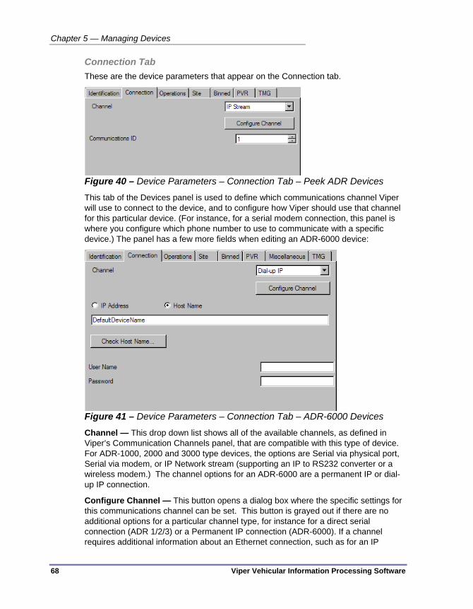
Chapter 5 — Managing Devices
68 Viper Vehicular Information Processing Software
Connection Tab These are the device parameters that appear on the Connection tab.
Figure 40 – Device Parameters – Connection Tab – Peek ADR Devices
This tab of the Devices panel is used to define which communications channel Viper will use to connect to the device, and to configure how Viper should use that channel for this particular device. (For instance, for a serial modem connection, this panel is where you configure which phone number to use to communicate with a specific device.) The panel has a few more fields when editing an ADR-6000 device:
Figure 41 – Device Parameters – Connection Tab – ADR-6000 Devices
Channel — This drop down list shows all of the available channels, as defined in Viper’s Communication Channels panel, that are compatible with this type of device. For ADR-1000, 2000 and 3000 type devices, the options are Serial via physical port, Serial via modem, or IP Network stream (supporting an IP to RS232 converter or a wireless modem.) The channel options for an ADR-6000 are a permanent IP or dial-up IP connection.
Configure Channel — This button opens a dialog box where the specific settings for this communications channel can be set. This button is grayed out if there are no additional options for a particular channel type, for instance for a direct serial connection (ADR 1/2/3) or a Permanent IP connection (ADR-6000). If a channel requires additional information about an Ethernet connection, such as for an IP

Device Parameters
Viper Vehicular Information Processing Software 69
Stream connection to a Peek ADR type device, the dialog box for addtional IP information will appear when the operator selections the Configure Channel button:
Figure 42 – Device-specific channel settings dialog box - IP
The meanings of these fields is exactly the same as those that appear on the main Connection tab for an ADR-6000 device, as described below.
If the device has a dialup connection, such as with a Dial-up IP connection for an ADR-6000, the dialog box that appears has these options:
Figure 43 – Device-specific channel settings dialog box – Dialup
The details about these additional dialup channel settings are also described below:
Communications ID — The communications ID is used by ADR-1000, 2000 and 3000 devices as an internal ID for communications when several devices may be located along a shared comms channel. The ID is set in the ADR unit and it must be unique along the shared communications line, which may be a multiplexer or some other type of shared comms network. The Communications ID can be any integer value between 1 and 65534. The Communications ID parameter is not used on ADR-6000 devices.
IP Address — These four octets (numbers between 0 and 255) represent a unique address on an Ethernet network. The combination of numbers must be unique within the network. The IP address can be replaced by a Host Name, but only if a host name server (a DNS server) is up and running within the network.

Chapter 5 — Managing Devices
70 Viper Vehicular Information Processing Software
Host name — This is another way to specify a device location on an Ethernet network, but it will only function if the network in question has a name server running, and that name server has the host name you’ve entered in its mapping table. The DNS Server stores a table of host names linked to their associated IP addresses.
Check Host Name button — This button only appears when the Host Name option has been selected. This tells Viper to test the Host Name that has been entered in the field above to see if the local name server has it on file. If the host name is not found, Viper will report that ‘No such host is known’. If the host name is found, Viper will report ‘Host Name <the name you entered> successfully resolved.’ This merely reports if a name server has successfully returned a valid IP address for that device name. This check does not test to see if the device at that IP is currently present on the network.
User Name — ADR-6000 devices require a user name and password in order for Viper to retrieve files and set parameters. The user name is case sensitive and there must be a valid account under this user name configured on the ADR-6000 device’s secured web service.
Password — ADR-6000 devices require a user name and password. This is where you store that password. It is case sensitive and can only contain letters and numbers. There must be a valid account under the above user name that has this password configured on the secure web server that is running on the ADR-6000 device.
Note When configuring an ‘IP via Modem’ connection to an ADR-6000, one must supply BOTH the PPP user name and password (entered on the Device Specific Parameters dialog box that is accessed by pressing the Configure Channel button) AND the user name and password described just above this note, which are located directly on the Connection tab in the Devices pane. The first login asks for permission to establish a PPP dialup IP connection to the ADR-6000 device, then the second User Name and Password are used to request access to the secure web server running on the ADR-6000.
Port Number — This is an integer value between 0 and 65535* that indicates which TCP port on the target device should be used to try to access that device. If the IP address is the building address for a device, the port can be thought of as an room number within that building. A port number is used only when communicating over an Ethernet (i.e. ‘IP’) network. Port numbers often come into play when configuring firewalls, whether external or internal, and applications that attempt to use individual ports to communicate.
* The Internet Assigned Numbers Authority (IANA) declares ports 49152 through 65535 as Dynamic and/or private ports. Because of this, they are often allowed through firewalls while other ports are not. The official list of port numbers, as tracked by the IANA, is available at www.iana.org/assignments/port-numbers.
Device Parameters
Viper Vehicular Information Processing Software 71
Dialup Device-Specific Parameters Specified phone number — The phone number must be specified for either ‘Serial connections via modem’ or ‘IP over Modem’ connections. In either case, we recommend that you enter the number without punctuation (no parentheses or hyphens), however commas can be included to add pauses in the dialing, as is customary for most modems. The exact formatting of the phone number, outside of these general guidelines, is dependent on what formatting your brand and model of modem will accept.
User — (ADR-6000 only) The ADR-6000 uses a PPP dialup IP connection. This user name is the PPP user login name which is required in order to establish an IP connection to the ADR-6000 device over a dial-up line. This login is separate from and independent of the user name and password that must be supplied for all IP connections to an ADR-6000, which are entered on the main Connection tab of the Devices panel for an individual device.
Password — (ADR-6000 only) The ADR-6000 uses a PPP dialup IP connection. This password is the PPP login password. This password is required in order to establish an IP connection to the ADR-6000 device over a dial-up line and it must match the user login that is specified in the field above. This user name and password is separate from and independent of the user name and password that must be supplied for all IP connections to an ADR-6000, which are entered on the main Connection tab of the Devices panel for an individual device.
Predefined Dial-Up network — This option allows the IP via Modem connection to an ADR-6000 to use a dial-up network that has already been configured in Windows. For instance, if you have set up a VPN network in Windows, with an ADR-6000 at the other end of the phone number, you can select that network and all of its predefined information, here. Viper will automatically list any such networks that are currently defined on your Windows computer here in a drop-down list.
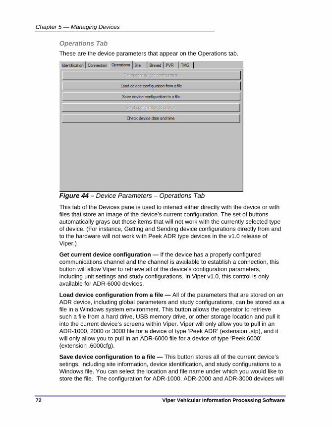
Chapter 5 — Managing Devices
72 Viper Vehicular Information Processing Software
Operations Tab These are the device parameters that appear on the Operations tab.
Figure 44 – Device Parameters – Operations Tab
This tab of the Devices pane is used to interact either directly with the device or with files that store an image of the device’s current configuration. The set of buttons automatically grays out those items that will not work with the currently selected type of device. (For instance, Getting and Sending device configurations directly from and to the hardware will not work with Peek ADR type devices in the v1.0 release of Viper.)
Get current device configuration — If the device has a properly configured communications channel and the channel is available to establish a connection, this button will allow Viper to retrieve all of the device’s configuration parameters, including unit settings and study configurations. In Viper v1.0, this control is only available for ADR-6000 devices.
Load device configuration from a file — All of the parameters that are stored on an ADR device, including global parameters and study configurations, can be stored as a file in a Windows system environment. This button allows the operator to retrieve such a file from a hard drive, USB memory drive, or other storage location and pull it into the current device’s screens within Viper. Viper will only allow you to pull in an ADR-1000, 2000 or 3000 file for a device of type ‘Peek ADR’ (extension .stp), and it will only allow you to pull in an ADR-6000 file for a device of type ‘Peek 6000’ (extension .6000cfg).
Save device configuration to a file — This button stores all of the current device’s setings, including site information, device identification, and study configurations to a Windows file. You can select the location and file name under which you would like to store the file. The configuration for ADR-1000, ADR-2000 and ADR-3000 devices will
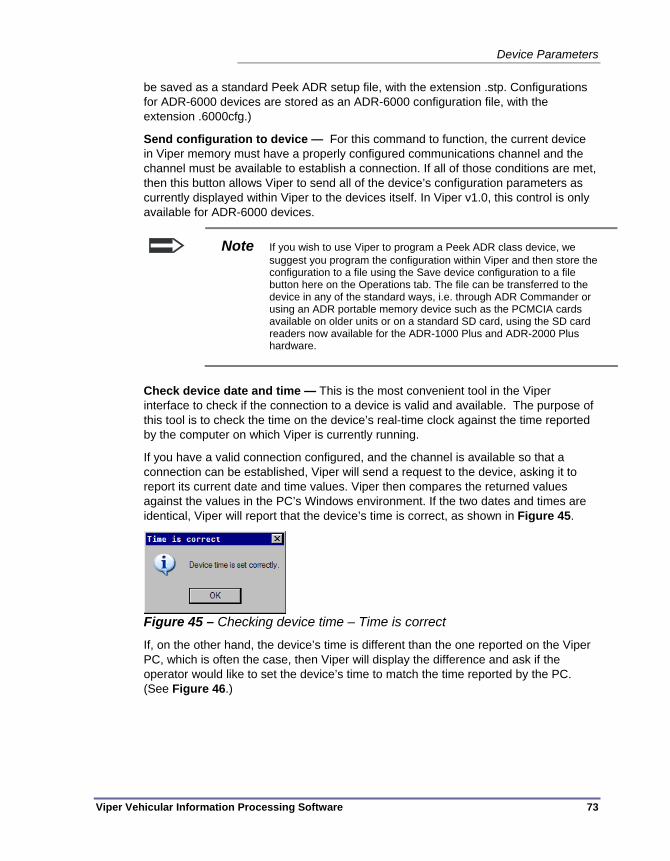
Device Parameters
Viper Vehicular Information Processing Software 73
be saved as a standard Peek ADR setup file, with the extension .stp. Configurations for ADR-6000 devices are stored as an ADR-6000 configuration file, with the extension .6000cfg.)
Send configuration to device — For this command to function, the current device in Viper memory must have a properly configured communications channel and the channel must be available to establish a connection. If all of those conditions are met, then this button allows Viper to send all of the device’s configuration parameters as currently displayed within Viper to the devices itself. In Viper v1.0, this control is only available for ADR-6000 devices.
Note If you wish to use Viper to program a Peek ADR class device, we suggest you program the configuration within Viper and then store the configuration to a file using the Save device configuration to a file button here on the Operations tab. The file can be transferred to the device in any of the standard ways, i.e. through ADR Commander or using an ADR portable memory device such as the PCMCIA cards available on older units or on a standard SD card, using the SD card readers now available for the ADR-1000 Plus and ADR-2000 Plus hardware.
Check device date and time — This is the most convenient tool in the Viper interface to check if the connection to a device is valid and available. The purpose of this tool is to check the time on the device’s real-time clock against the time reported by the computer on which Viper is currently running.
If you have a valid connection configured, and the channel is available so that a connection can be established, Viper will send a request to the device, asking it to report its current date and time values. Viper then compares the returned values against the values in the PC’s Windows environment. If the two dates and times are identical, Viper will report that the device’s time is correct, as shown in Figure 45.
Figure 45 – Checking device time – Time is correct
If, on the other hand, the device’s time is different than the one reported on the Viper PC, which is often the case, then Viper will display the difference and ask if the operator would like to set the device’s time to match the time reported by the PC. (See Figure 46.)

Chapter 5 — Managing Devices
74 Viper Vehicular Information Processing Software
Figure 46 – Checking device time – Times do not match
Selecting Yes will change the date and time on the ADR or ADR-6000 device. Selecting No will allow the device to retain its current date and time settings. In either case, Viper will then return control to the Operations tab for whatever action the user wishes to perform next. The only exception to this is if the operator selects Yes to change the device time, but the ADR is currently busy (for example, if it is currently recording a study.) If this occurs, then Viper will report that the time cannot be changed immediately.
Figure 47 – Setting device time when the device is busy
When the software encounters this situation, Viper will program the ADR to make an adjustment of N minutes/seconds in the appropriate direction at the time the ADR believes is midnight. This is only supported in Peek ADR v6.08 and later firmware for ADR-1000, 2000, and 3000 hardware. This delayed time sync feature is not supported in the ADR-6000.
Note ADR-6000 devices do not typically need to use the manual Viper time sync command at all, although it does work. However, the ADR-6000, being potentially network connected, can usually maintain its clock better by using a time server. The ADR-6000 also allows the time to be changed immediately even when a study is running, so the message shown in Figure 47 should never appear.

Device Parameters
Viper Vehicular Information Processing Software 75
Site Tab These are the device parameters that appear on the Site tab. They deal with device and location identification and the detection hardware that is available at that location.
Figure 48 – Device Parameters – Site Tab
The Site tab is the same no matter whether you are editing a Peek ADR or an ADR 6000 device.
Site ID — The Site ID is a unique identifier for each ADR device. It is used by both Peek ADR class devices (ADR-1000, 2000, and 3000) and ADR-6000 devices. It is a 12 digit alphanumeric identifier that is used to tag study data files in both TOPS and Viper. It’s uniqueness is not enforced. It is merely a very good idea to maintain unique Site IDs for all hardware in your control in order to avoid confusion among devices and their resulting data files. By default, the unique ‘Electronic Serial Number’ (ESN) is coded at the factory as the Site ID for all Peek ADRs and ADR-6000 units, but this identifier can be edited on the hardware.
The Site ID cannot use spaces or punctuation, but it will accept numbers and letters. It must be 12 digits in length; no more, no less.
Station Number — Whereas the Site ID is required, the Station Number is an optional secondary method to identify a device and location. It can be thought of as an extension of the Site ID that is not used for file tagging or device management, however both the Site ID and Station Number are included in the header information for all ADR setup and data files. Many ADR operators use the Station Number as a method to describe the location of the device. Station number can include letters, numbers, spaces and punctuation. In Viper, the Site ID and Station Number are used by the automated processing to attach device-specific metadata required by various output formats. For example the PRN format includes information about the direction traffic is travelling, but that information is not stored in the ADR. To ensure that the correct metadata is used, the Site ID and Station Number configured in this tab must match the Site ID and Station Number set in the ADR. If they do not, then the automatic processing service will not be able to find the correct metadata, or worse, may apply information intended for one site to a different one.

Chapter 5 — Managing Devices
76 Viper Vehicular Information Processing Software
Number of Arrays — The sensors that an ADR uses to detect traffic are arranged in a traffic lane in an ‘array’. The complexity of the array depends on the type of data being detected. Studies that only gather traffic counts may only include a single detector, while volume, speed, and separation studies may include many sensors, especially when performed by an ADR-6000. This parameter allows you to program how many arrays are used by the device, and once the number is set new fields appear below, allowing you to provide additional information about the direction and type of traffic flow for that array. The number of arrays information is used when editing the fields on the PVR tab. The channel settings beneath each array is used to determine what data goes into a TMG report.
Figure 49 – Adding additional arrays to the device
Channel # — A single channel appears for each array that you specify in the Number of arrays field, numbered sequentially. (‘Channel 1’, ‘Channel 2’, etc.) The field to the right of this channel number allows one to set the direction of traffic flow for that channel.
Lane — Each channel of an array can be set to function in a specific lane in a direction of travel. Selecting nothing indicates that the channel covers all lanes of the direction. It is a requirement of the TMG processing that Lane 1 is considered to be the ‘slow’ lane of that direction of traffic flow.
TMG Volume — A check in this checkbox indicates that this channel is used to generate data for the TMG volume export.
TMG Class — A check in this checkbox indicates that this channel is used to generate data for the TMG vehicle class export.
TMG Weight — A check in this checkbox indicates that this channel is used to generate data for the TMG vehicle weight export.

Device Parameters
Viper Vehicular Information Processing Software 77
Binned Tab These are the device parameters that appear on the Binned tab.
Figure 50 – Device Parameters – Binned Tab
These parameters can be used to define a binned study for the device. A ‘binned’ study means that the device is being used to classify the vehicles that pass over its sensors into various ‘bins’ of data. A binned study is a counting study, in that the results are the numbers of vehicles that fall into a particular bin. The information that is provided by such a study is determined by the way that the bins are defined. For instance, bins can be based on the channel in which traffic flows (i.e. the direction of travel and/or lane), the weights of vehicles, vehicle speeds, lengths, classifications, etc.) Basically, bins can be based on any data that can be gathered on the vehicles by the available sensors.
Note Binned study configuration is of limited usefulness in Viper v1.0, since binned studies are typically performed by Peek ADR class devices and Viper is currently unable to send configuration files directly to such devices. Binned studies can be configured in this environment, but can only be loaded to the device using some other tool, such as ADR commander.
It is important to keep in mind that the binned study tab of Viper allows the operator to program a binned study based on any type of data that may be available, not based on what specific sensors are available on this particular device. Consequently, it is important for the operator to keep in mind what hardware sensors are available on the device in question when defining a binned study in this environment.

Chapter 5 — Managing Devices
78 Viper Vehicular Information Processing Software
Add button — The Add button is used to begin programming a study. The Viper allows multiple studies to be created for a device. Just press the Add button on the next Study down to start programming a new one.
Bin Type (‘Channel’ in our example) — The field that shows up in the left column of the Study area indicates one dimension in the binning of data. This is the parameter on which the study will sort the vehicles into bins. For example, if this is selected to be a Speed dimension, then the bins might be ‘Less than 10mph’, ’10 to 20mph’, ’20 to 30mph’, and so on, and vehicles would be counted in those bins based on how fast they were traveling when they passed over the sensor array. Up to three dimensions can be defined, and binning occurs from top to bottom as described on this tab. Select ‘None’ if you do not wish to use this dimension of the bin study.
Number — The number of bins along this dimension of the study. This number determines how many range definition fields will appear to the right of the number. (The actual number will be the selected number minus 1, since the outer boundary conditions are self evident.)
Range selection — These ranges define the edge conditions of the bins in this dimension of the study. These range values are numerical; integer where appropriate (class, channel), floating point where appropriate (everything else.) In range selections, only the upper limit is inclusive (meaning that a range from ‘1 to 2’ will not count a vehicle with a value of 1, but does count one with a value of 2.)
Remove button — The remove button discards this study definition.
When finished editing the Binned study parameters, be sure to click Apply to save the settings.
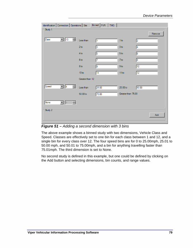
Device Parameters
Viper Vehicular Information Processing Software 79
Figure 51 – Adding a second dimension with 3 bins
The above example shows a binned study with two dimensions, Vehicle Class and Speed. Classes are effectively set to one bin for each class between 1 and 12, and a single bin for every class over 12. The four speed bins are for 0 to 25.00mph, 25.01 to 50.00 mph, and 50.01 to 75.00mph, and a bin for anything travelling faster than 75.01mph. The third dimension is set to None.
No second study is defined in this example, but one could be defined by clicking on the Add button and selecting dimensions, bin counts, and range values.

Chapter 5 — Managing Devices
80 Viper Vehicular Information Processing Software
PVR Tab These are the device parameters that appear on the PVR tab.
Figure 52 – Device Parameters – PVR Tab – Recording OFF
This tab allows an operator to define a ‘Per Vehicle Record’ study for the ADR. Per vehicle record studies record a line of data for each vehicle that passes over any detection array attached to the device, so they generate a great deal more data than a binned study. With this in mind, it is important to keep the memory capabilities of your ADR device in mind when designing a PVR study.
To begin programming a PVR study, place a check in the Record PVR data checkbox.
Note Study definition is of limited usefulness in Viper v1.0, since the program is currently unable to send configuration files directly to Peek ADR class devices. Binned studies can be configured in this environment, but can only be loaded to those device using some other tool, such as ADR commander. PVR studies defined for ADR-6000 devices can be sent directly to the device using Viper.
Record PVR data — This checkbox is used to indicate that this device will perform a ‘per vehicle record’ study. When this box is checked, all of the other controls and fields on the PVR field become available for use.

Device Parameters
Viper Vehicular Information Processing Software 81
Figure 53 – Device Parameters – PVR Tab – Recording ON
The fields on this tab become available for use if you click on the Record PVR data checkbox. Use these fields to define which vehicle classes and which sensor arrays will be used to generate PVR data, and which pieces of information to record in the data file. Be aware that every piece of data that is added to the study will increase the memory requirement of the study.
For X classes — You can opt to include all vehicles in the PVR study (‘For all classes’) or only the heavier vehicles (‘For classes 4 and higher’).
on all arrays checkbox — When checked, this option grays out the Array selection checkboxes in the area below this box, and the device will record PVR records for vehicles on all of its available detection arrays. If not checked, you have the option select individual arrays below.
Array selector checkboxes — Place a check in the box next to the arrays that you want to include in the PVR study. Vehicles that pass over arrays that are NOT selected (as long as the ‘on all arrays’ box is not checked) will NOT be included in this PVR study.
What information should be included — Use the checkboxes in this area to determine which pieces of information to include in each PVR record.
Number of axles — Tells Viper to include the number of axles belonging to each vehicle in the PVR record for that vehicle.
Class — Include the class each vehicle belongs to in the PVR records. Classes can be based on the standard 14 class FHWA standard in the United States, or it can be

Chapter 5 — Managing Devices
82 Viper Vehicular Information Processing Software
customized using a Class definition tool such as the TOPS ADR Class Tree Editor. The class tree is stored in the ADR. Viper has no way to define a custom class tree on its own, but it will not interfere with the existing tree defined in the device or in an ADR setup file.
Gap — Tells Viper to include the distance between this vehicle and the one behind it in each PVR data record.
Total wheelbase — Tells Viper to include the total wheelbase length (i.e. the distance between the first and last axle belonging to the vehicle) in the PVR file.
Road Temperature — Tells Viper to include the road temperature in the PVR record. This is the temperature at the sensor location at the time the vehicle was detected.
Gross weight — Tells Viper to include the total vehicle weight in the PVR record for each vehicle. The method used to generate this value is different for different types of sensors, but it is essentially a summation of the axle weights of all of the axles that are judged to be part of the vehicle.
Axle weights — Tells Viper to include the individual axle weight readings in the PVR record for each axle in each vehicle.
Speed — Tells Viper to record the speed of each vehicle in the PVR record, if that data is available from the sensors.
Headway — Tells Viper to include the distance between this vehicle and the one in front of it in each PVR data record.
Magnetic (loop) length — Tells Viper to include the length of the vehicle as recorded by a magnetic loop (inductance) sensor. This length will likely be different from an axle detection-based length calculation, since the loop may be able to detect the metal of the vehicle motor or other vehicle parts that have a high density of metal and extend beyond the first and last axles.
Vehicle Status — Tells Viper to include the status information from this vehicle detection in the PVR data record. The status information is a hexadecimal representation of two binary status bytes. Indicates the status of the sensor array at the time of the vehicle detection.
Vehicle Number — The Vehicle Number is a simple integer that is raised by one every time a vehicle is detected (on any array) during the study. Each vehicle detected during the study has a unique vehicle number. This checkbox tells Viper to include the vehicle number in the PVR vehicle record.
Axle spacings — Tells Viper to include the distance information between each contiguous pair of axles in the vehicle, in the PVR record.
Wheel weights — If the ADR is connected to a special wheel-sensing array, this checkbox tells Viper to include weight information in the PVR record for each wheel in the vehicle.

Device Parameters
Viper Vehicular Information Processing Software 83
Acceleration — If the ADR sensor array has the capability (typically only ADR-6000s can perform this calculation), this option tells Viper to include vehicle acceleration data in the PVR record for each vehicle.
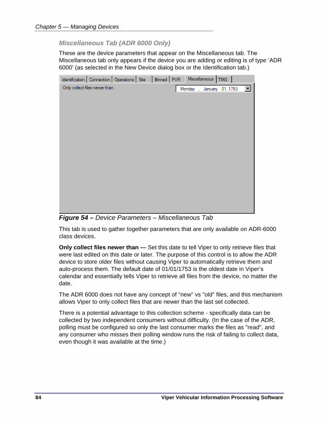
Chapter 5 — Managing Devices
84 Viper Vehicular Information Processing Software
Miscellaneous Tab (ADR 6000 Only) These are the device parameters that appear on the Miscellaneous tab. The Miscellaneous tab only appears if the device you are adding or editing is of type ‘ADR 6000’ (as selected in the New Device dialog box or the Identification tab.)
Figure 54 – Device Parameters – Miscellaneous Tab
This tab is used to gather together parameters that are only available on ADR-6000 class devices.
Only collect files newer than — Set this date to tell Viper to only retrieve files that were last edited on this date or later. The purpose of this control is to allow the ADR device to store older files without causing Viper to automatically retrieve them and auto-process them. The default date of 01/01/1753 is the oldest date in Viper’s calendar and essentially tells Viper to retrieve all files from the device, no matter the date.
The ADR 6000 does not have any concept of "new" vs "old" files, and this mechanism allows Viper to only collect files that are newer than the last set collected.
There is a potential advantage to this collection scheme - specifically data can be collected by two independent consumers without difficulty. (In the case of the ADR, polling must be configured so only the last consumer marks the files as "read", and any consumer who misses their polling window runs the risk of failing to collect data, even though it was available at the time.)

Device Parameters
Viper Vehicular Information Processing Software 85
TMG Tab These are the device parameters that appear on the TMG tab.
Figure 55 – Device Parameters – TMG Tab
Viper has the ability to output TMG-compliant reports on vehicle studies. TMG is a reporting standard defined within the U.S. Federal Highway Administration’s ‘Traffic Monitoring Guide’, which is available at:
http://www.fhwa.dot.gov/ohim/tmguide/
(For all of the items in this tab, refer to the discussion in Section 6.2 of the Traffic Monitoring Guide.)
This tab is where you select values for the various TMG-specified vehicular study site data points. These values must be selected correctly for the FHWA to accept the report.
TMG Stations Identification — This field should contain an alphanumeric designation for the station where the survey data are collected. There should be no embedded blanks.
Functional Class — This is a code representing the type of roadway where the study was performed. Although the final report will use the numeric code, Viper allows you to simply select the class by description from the drop-down box.
Table 6 – TMG Functional Classes Code Classification Description RURAL 01 Principal Arterial - Interstate 02 Principal Arterial - Other 06 Minor Arterial

Chapter 5 — Managing Devices
86 Viper Vehicular Information Processing Software
Code Classification Description 07 Major Collector 08 Minor Collector 09 Local System URBAN 11 Principal Arterial - Interstate 12 Principal Arterial - Other
Freeways or Expressways 14 Principal Arterial - Other 16 Minor Arterial 17 Collector 19 Local System
Classification Algorithm — This describes how the study was performed, meaning what was the methodology used to count and classify vehicles. Your choice here should not be any of the first three options on the list, but otherwise is dependent on the type of detection arrays being used. These are the options:
Not Specified
Human observation on site (manual)
Human observation of vehicle image (e.g., video)
Automated interpretation of vehicle image or signature (e.g., video, microwave, sonic)
Vehicle length classification
Axle spacing with ASTM Standard E1572
Axle spacing with Scheme F
Axle spacing with Scheme F modified
Other axle spacing algorithm
Axle spacing and weight algorithm
Axle spacing and vehicle length algorithm
Axle spacing, weight, and vehicle length algorithm
Axle spacing and other input(s) not specified above
Other means not specified above
Classification Scheme — This describes the method used to divide the vehicle traffic up into different classes of vehicle. Many use the standard ‘FHWA’s standard 13 class system’, but these other options are available:
One class: total volume
Two classes: non-commercial (classes 1-3) and commercial (classes 4-13) vehicles

Device Parameters
Viper Vehicular Information Processing Software 87
Three classes: non-commercial (classes 1-3), single-unit commercial (classes 4-7), combination commercial (classes 8-13) vehicles
Four classes: non-commercial (classes 1-3), single -unit commercial (classes 4-7), single-trailer commercial (classes 8-10), multi-trailer commercial (classes 11-13) vehicles
Five classes as follows:
two-axle, two or four-tire vehicles (classes 1-3)
buses (class 4)
single -unit trucks (classes 5-7)
single -trailer combination trucks (classes 8-10)
multiple-trailer combination trucks (classes 11-13)
FHWA's standard 13 class system (see Appendix 4-C)
FHWA's 13 class system plus a class 14 (State or vendor defined)
FHWA's 13 class system plus classes 14 and 15 (State or vendor defined)
Other numbers = number of classes (unsupported)
Weight Sample Type — This specifies the sample type used to get truck weights. The available options are:
Not Specified
TMG and SHRP/LTPP (Station used for TMG sample and Strategic Highway Research Program (SHRP) Long Term)
SHRP/LTPP Only (Station used for SHRP/LTPP sample, but not TMG sample)
TMG Only (Station used for TMG sample, but not SHRP/LTPP sample)
Station not used for any of the above
Weighing Method — This specifies how vehicles are weighed at the station:
Portable static scale
Chassis -mounted, towed static scale
Platform or pit static scale
Portable weigh-in -motion system
Permanent weigh-in-motion system
Weight Calibration Mechanism — This specifies the method used to calibrate the weighing system, for example by comparing weight-in-motion against weights from static scales.
ASTM Standard E1318

Chapter 5 — Managing Devices
88 Viper Vehicular Information Processing Software
Subset of ASTM Standard E1318
Combination of test trucks and trucks from the traffic stream (but not ASTM E1318)
Other sample of trucks from the traffic stream
Moving average of the steering axle of 3S2s
Static calibration
Test trucks only
Un-calibrated
Other method
Data Retrieval — This field specifies how the data was retrieved from the device back to the report generation location. For Viper, this should be set to Automated.
Primary Sensor Type — The detection sensor type that is most useful in collecting this vehicle classification data:
Automatic vehicle identification (AVI)
Bending plate
Capacitance strip
Capacitance mat/pad
Hydraulic load cells
Fiber optic
Strain gauge on bridge beam
Human observation (manual)
Infrared
Laser/lidar
Inductance loop
Magnetometer
Piezoelectric
Quartz piezoelectric
Road tube
Sonic/acoustic
Tape switch
Ultrasonic
Microwave

Device Parameters
Viper Vehicular Information Processing Software 89
Radio wave
Other
Secondary Sensor Type — If another type of sensor is used in a secondary role for determining vehicle classification, please specify it here, using any of the same types listed on the Primary Sensor Type field. The additional option is to select ‘Not Specified’, if there is no secondary sensor used for the study.
Primary purpose — What is the primary purpose for installing the station and hence which organization is responsible for it and supplies the data.
Enforcement purposes (e.g., speed or weight enforcement)
Operations purposes in support of ITS initiatives
Load data for pavement design or pavement management purposes
Operations purposes but not ITS
Planning or traffic statistics purposes
Research purposes (e.g., LTPP)
LRS Identification — LRS stands for Linear Referencing System. The LRS dentification reported in this item for the station must be the same as the LRS identification reported in the HPMS for the section of roadway where the station is located. The LRS identification is a 12-character value, which can be alphanumeric, but must not contain blanks. More information concerning the LRS may be found in Chapter V of the HPMS Field Manual, “Linear Referencing System Requirements”.
LRS Location Point — This is the LRS location point for the station. It is similar information to the LRS Beginning Point and LRS Ending Point in the HPMS. The KMPT for the station must be within the range of the LRS beginning point and LRS ending point for the roadway section upon which the station is located. It is coded in kilometers with an implied decimal in the middle: XXX.XXX.
SHRP Site Identification — If the site is used in an SHRP/LTPP sample, this is where you supply the SHRP site ID.
Previous TMG Station Identification — If the station replaces another station, give the station ID that was used previously.
Year Established — This is where you enter the last two digits of the year that this station was created.
Year Discontinued — This is where you would enter the last two digits of the year that this site stops being used for TMG reporting, if such information is available.
HPMS Sample Type — This is where you specify whether this station was on a Highway Performance Monitoring System standard sample section. For more details, refer to the HPMS Field Manual.

Chapter 5 — Managing Devices
90 Viper Vehicular Information Processing Software
HPMS Identification — If the station was in fact part of an HPMS sample section, please enter the HPMS Sample Identification, as per the HPMS Field Manual, Item 47.
Site is part of the National Highway System — Specify whether the site is or is not located on the National Highway System.
Posted Route Signing — This is the same as the Route Signing item in the HPMS Field Manual, Item 22, and can have one of the following values:
Not signed
Interstate
U.S.
State
Off-Interstate Business Marker
County
Township
Municipal
Parkway or Forest Route Marker
None of the above
Posted Route Number — Specify the route number of the principal route on which the station is located. If the station is located on a city street, leave this field blank. This is the same as Signed Route Number in HPMS Field Manual (Item 24).
Concurrent Route Signing — This field uses the same values as the Posted Route Signing field above, in case the location has multiple designations.
Concurrent Route Number — Similar to the Posted Route Number, but this indicates the Concurrent Route Signing at this site location.
Location Description — For stations located on a numbered route, enter the distance and direction of the station from the nearest major intersecting route or state border or landmark that is visible on state road maps. If the station is located on a city street, enter the city and street name. Abbreviate if necessary. (50 characters maximum)

Viper Vehicular Information Processing Software 91
Chapter 6 — Auto Processing
This chapter describes the Auto-processing programming interface of the Viper front end software. The following topics are discussed in detail in this chapter:
• An overview of auto-processing programming in Viper, on page 92.
• An introduction to the programming interface, on page 93.
• A summary of the available processing actions, on page 106.
• Several examples of workflows programmed in the interface, on page 119.
Chapter 6 — Auto Processing
92 Viper Vehicular Information Processing Software
OVERVIEW The Viper Automatic Processing Module provides a mechanism to automatically perform a predefined sequence of tasks, called a ‘workflow’.
When creating a workflow in the version 1.0 Auto-processing panel, the following tasks are available:
Watch a folder for data files
Sort files by the type of data they contain.
Perform data adjustments associated with Daylight Savings Time (DST).
Merge files from multiple sites into a single virtual site (Can also be used to modify channel assignments, and produce a summarized output file - e.g. count by direction)
Generate a PRN Export
Generate an XML representation of binned data
Move a file to another location (this includes optional generation of a folder structure based on data criteria such as when it was recorded, and what station it came from)
Generate a report from the data.
The automatic processing functionality is implemented as two separate components. The Automatic Processing Service runs in the background and is the part that actually moves files and processes the data. The Automatic Processing Configuration interface runs as part of the Viper front end and is used to set up how the service will perform its tasks. The configuration tool allows users to view and modify the processing configuration that is run on the back end service. After a processing configuration has been created in the interface, it can be stored to a file, or it can be sent to the service (i.e. activated) where it can then process your incoming ADR data.
A single auto-processing configuration can contain multiple workflows, each performing related or independent tasks on incoming data files. (Up to 20 workflows can be configured in a single configuration file; however most users will only require from one to four workflows in their auto-processing configuration file.) Every workflow must start with a Watch folder, which is a location on your local system or on a network server where data files will be placed for Viper to retrieve.
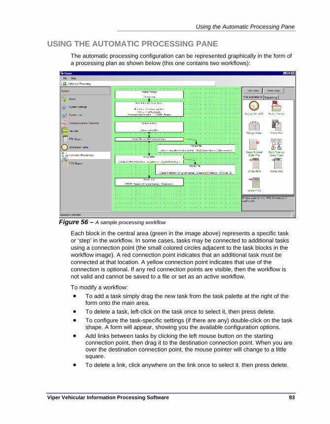
Using the Automatic Processing Pane
Viper Vehicular Information Processing Software 93
USING THE AUTOMATIC PROCESSING PANE The automatic processing configuration can be represented graphically in the form of a processing plan as shown below (this one contains two workflows):
Figure 56 – A sample processing workflow
Each block in the central area (green in the image above) represents a specific task or ‘step’ in the workflow. In some cases, tasks may be connected to additional tasks using a connection point (the small colored circles adjacent to the task blocks in the workflow image). A red connection point indicates that an additional task must be connected at that location. A yellow connection point indicates that use of the connection is optional. If any red connection points are visible, then the workflow is not valid and cannot be saved to a file or set as an active workflow.
To modify a workflow: To add a task simply drag the new task from the task palette at the right of the
form onto the main area. To delete a task, left-click on the task once to select it, then press delete. To configure the task-specific settings (if there are any) double-click on the task
shape. A form will appear, showing you the available configuration options. Add links between tasks by clicking the left mouse button on the starting
connection point, then drag it to the destination connection point. When you are over the destination connection point, the mouse pointer will change to a little square.
To delete a link, click anywhere on the link once to select it. then press delete.

Chapter 6 — Auto Processing
94 Viper Vehicular Information Processing Software
Launching the Auto-Processing Module Automatic processing plans, also known as ‘configurations’, are edited in Viper using the Automatic Processing pane. Click on Automatic Processing in the navigation bar to open the module.
Figure 57 – Automatic Processing pane
Click here to view & edit automatic processing configurations
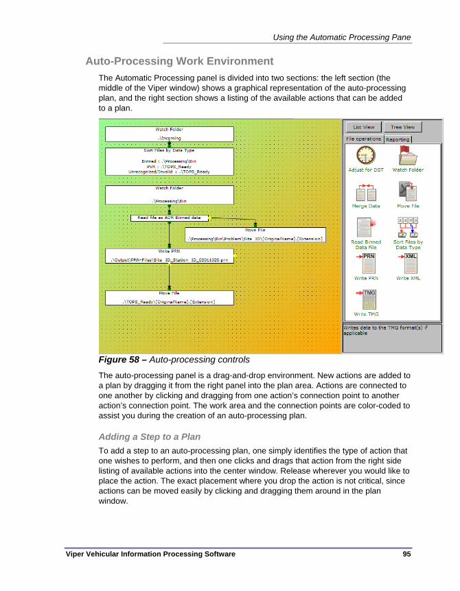
Using the Automatic Processing Pane
Viper Vehicular Information Processing Software 95
Auto-Processing Work Environment The Automatic Processing panel is divided into two sections: the left section (the middle of the Viper window) shows a graphical representation of the auto-processing plan, and the right section shows a listing of the available actions that can be added to a plan.
Figure 58 – Auto-processing controls
The auto-processing panel is a drag-and-drop environment. New actions are added to a plan by dragging it from the right panel into the plan area. Actions are connected to one another by clicking and dragging from one action’s connection point to another action’s connection point. The work area and the connection points are color-coded to assist you during the creation of an auto-processing plan.
Adding a Step to a Plan To add a step to an auto-processing plan, one simply identifies the type of action that one wishes to perform, and then one clicks and drags that action from the right side listing of available actions into the center window. Release wherever you would like to place the action. The exact placement where you drop the action is not critical, since actions can be moved easily by clicking and dragging them around in the plan window.
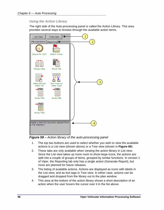
Chapter 6 — Auto Processing
96 Viper Vehicular Information Processing Software
Using the Action Library The right side of the Auto-processing panel is called the Action Library. This area provides several ways to browse through the available action items.
Figure 59 – Action library of the auto-processing panel
1. The top two buttons are used to select whether you wish to view the available actions is a List view (shown above) or a Tree view (shown in Figure 60).
2. These tabs are only available when viewing the action library in List view. Since the List view takes up more room to show large icons, the actions are split into a couple of groups of items, grouped by similar functions. In version 1 of Viper, the Reporting tab only has a single action (Generate Report), but more are planned for future releases.
3. The listing of available actions. Actions are displayed as icons with labels in the List view, and as text tags in Tree view. In either case, actions can be dragged and dropped from the library out to the plan window.
4. This area at the bottom of the action library shows a short description of an action when the user hovers the cursor over it in the list above.
1
2
3
4
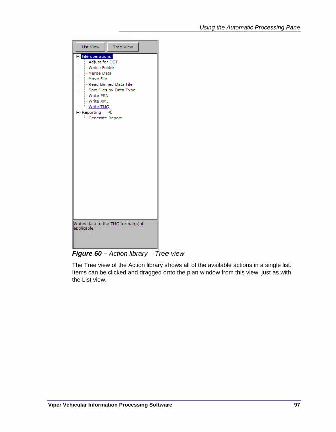
Using the Automatic Processing Pane
Viper Vehicular Information Processing Software 97
Figure 60 – Action library – Tree view
The Tree view of the Action library shows all of the available actions in a single list. Items can be clicked and dragged onto the plan window from this view, just as with the List view.

Chapter 6 — Auto Processing
98 Viper Vehicular Information Processing Software
Connecting Two Steps in a Plan The key to the creation of an action plan is to link actions in a logical manner, one to the next, until you’ve accomplished everything you need to do with the data. After an action has been dragged to the plan window from the Action library, connection points on the sides of the box that represents the action are used to draw lines from one box to another. A Yellow connection point indicates an optional connection, meaning the connection can be made, or not, for the plan to be valid.
Figure 61 – Identify steps to connect
A red conneciton point indicates that a link MUST be made at this point for the plan to be valid. In this example, we want to create an error handling action on the Write PRN action. We start by clicking on the yellow icon on the side of the Write PRN action box. The connection point will turn green, indicating that you have successfully grabbed the link.
Figure 62 – Select a flow point
Now drag the connection to the action you intend to perform next if an error is encountered in the Write PRN action.
Figure 63 – Drag a connecting line

Using the Automatic Processing Pane
Viper Vehicular Information Processing Software 99
Place the cursor over the connection point of the second action item. Notice that the placement of the cursor is critical for a successful connection to be made. You are in the right place, when the connection point turns green and is surrounded by a black outline.
Figure 64 – Drop the line on a flow point
Let go of the cursor button at this point to make the connection. The connection will turn into a logical connection line, with an arrow at the end, indicating data flow.
Figure 65 – Completed connection between two steps

Chapter 6 — Auto Processing
100 Viper Vehicular Information Processing Software
Reorganizing a Workflow Diagram The best way to edit and design a workflow in the plan window is to keep everything organized and uncluttered. To maintain clarity, keep the action boxes spatially separated and try to avoid crossing connection lines. Use the following tools to organize the plan area to your satisfaction.
Dragging Steps to New Locations
Each action box can be relocated within the plan area easily, and the location of the action (or the workflow) relative to the rest of the actions or workflows, has no impact on how the plan performs. It is merely cosmetic. All connections will be maintained when action boxes are moved.
To move an action box to a new location, click on the box so that the box controls appear. These include a change in the cursor, and edge and corner handles just outside of the box.
Figure 66 – Click a step to see move cursor
When the box controls appear, click and drag inside of the box to move it.
Figure 67 – Step in a new location
When the action item is in the desired location, let go of the cursor to drop the item.

Using the Automatic Processing Pane
Viper Vehicular Information Processing Software 101
Resizing a Step Box
To change the size of an action box, click on the action so that the box controls appear. The white handles that appear around the outside of the box can be used to drag the box shape to a new size. Corner handles resize the entire rectangle, while edge handles just stretch the box along that dimension.
Figure 68 – Click on a step box to see the resize controls
Here we click and drag on an edge handle to shrink the box to a smaller horizontal size. When you are finished, and happy with the size of the action box, let go of the handle.
Figure 69 – The resized step box
Note If the action box is currently located such that part of it falls outside of the plan area, the white handles will not resize the box. Instead, they will move the box. Resizing can only be performed when the action box is entirely visible within the visible plan area.
Deleting a Step in a Workflow Deleting a step (or action) in a workflow is very simple. Just select the action box and press the Delete key.
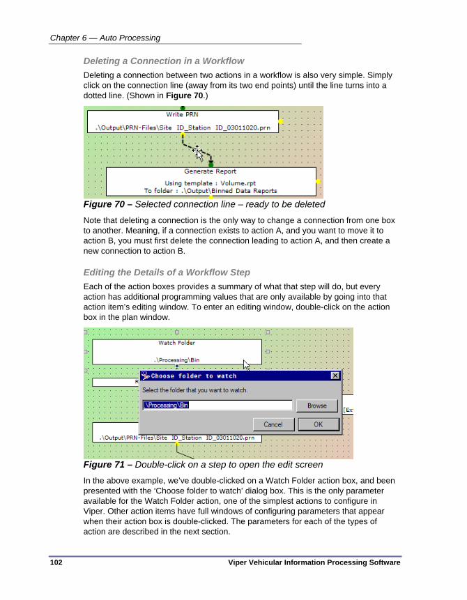
Chapter 6 — Auto Processing
102 Viper Vehicular Information Processing Software
Deleting a Connection in a Workflow Deleting a connection between two actions in a workflow is also very simple. Simply click on the connection line (away from its two end points) until the line turns into a dotted line. (Shown in Figure 70.)
Figure 70 – Selected connection line – ready to be deleted
Note that deleting a connection is the only way to change a connection from one box to another. Meaning, if a connection exists to action A, and you want to move it to action B, you must first delete the connection leading to action A, and then create a new connection to action B.
Editing the Details of a Workflow Step Each of the action boxes provides a summary of what that step will do, but every action has additional programming values that are only available by going into that action item’s editing window. To enter an editing window, double-click on the action box in the plan window.
Figure 71 – Double-click on a step to open the edit screen
In the above example, we’ve double-clicked on a Watch Folder action box, and been presented with the ‘Choose folder to watch’ dialog box. This is the only parameter available for the Watch Folder action, one of the simplest actions to configure in Viper. Other action items have full windows of configuring parameters that appear when their action box is double-clicked. The parameters for each of the types of action are described in the next section.

Using the Automatic Processing Pane
Viper Vehicular Information Processing Software 103
Color Coding in the Plan Area The background color of the Automatic Processing plan area is coded to provide information about the current state of the visible plan. There are two colors used to provide information, which are blended into one another to provide the full window color gradient.
Figure 72 – Color coding corners of the auto-processing plan area
The top left corner displays a color indicating where the visible plan came from:
Green — The plan came from the live Viper auto-processing service
Blue — The plan came from a stored configuration file (.psm file)
The bottom right corner shows a color that represents how the displayed plan compares to the source version:
Green — The displayed plan is identical to the plan in the source location
Orange — The displayed plan is different from the plan in the source location, but only in a cosmetic aspect (i.e. an action box has been moved or resized)
Red (Pink) — The displayed plan is logically different from the plan in the source location (i.e. an action has been added or deleted, or the configuration parameters for a plan have been modified)
So, from the above color coding descriptions, we can see that the plan shown in Figure 72 (which is green across the entire window) is identical to the live plan that is currently running in the Viper auto-processing service.
Source of the currently displayed plan
Change status of the currently displayed plan

Chapter 6 — Auto Processing
104 Viper Vehicular Information Processing Software
Figure 73 – Another color coding for a displayed plan (unchanged from file)
This above plan background goes from blue in the top left to green in the bottom right corner (for those of you who are not seeing the color version of this screen capture). This represents a plan that was loaded from a file and has not been changed since it was opened.
If we were to resize the bottom Move File action, we would see a plan background that goes from Blue (top left) to Orange (bottom right):
Figure 74 – Plan changed cosmetically from its file source
If we then edit the file destination of the bottom Move File action, the color coding goes to Blue at the top left corner and Pink at the bottom right, as shown in Figure 75.

Using the Automatic Processing Pane
Viper Vehicular Information Processing Software 105
Figure 75 – Plan from file with edited logic
But then, if we make the currently displayed configuration active, we will get a visible plan that is back to our starting color code (Green to Green), since we are once again seeing a plan that is identical to the one being run by the Viper auto-processing service.
Figure 76 – Color coding after we send the visible plan to the service
The orange and pink coding will also, of course, be seen when we modify the live service plan. So we would see a green to orange gradient for cosmetic changes, and green to pink for logical changes.

Chapter 6 — Auto Processing
106 Viper Vehicular Information Processing Software
AVAILABLE PROCESSING COMPONENTS These are detailed descriptions of each of the actions that are available in the Viper automatic processing module.
Watch Folder Every workflow within a automatic processing plan must start with a watch folder. A file appearing in an ‘inbox’ folder is what triggers all action chains in Viper auto-processing.
Figure 77 – Watch Folder parameters dialog box
The only parameter required to define a Watch Folder action is the name of the folder you want the service to watch. You can either type in the directory name directly, or you can use the Browse button to find the folder that way. In all cases, a period at the start of the directory address represents the default Viper data directory, as defined in the System Settings pane. (Double periods tell the service to ‘go up one directory level from the default data folder’. This can be repeated using multiple double periods (a la ‘..\..\..\Viperdata\Processing\Bin’), which goes up three levels above the default data directory and then down into folders called ‘Viperdata’, then ‘Processing’, then ‘Bin’.
Adjust for DST This action is only applicable to ADR-6000 data. (It will not have any effect on data from ADR-1000/2000/3000 devices.) It is included in the Viper action list because of the way that ADR-6000 manages daylight savings time while tagging data points. Namely, the ADR-6000 adjusts for daylight saving time in a way that other data processing suites, such as TOPS or Excel, find invalid. This action turns the DST-effected data into data that can be used by any data processing software.
Figure 78 – Adjust for DST parameters dialog box

Available Processing Components
Viper Vehicular Information Processing Software 107
Archive modified files in — This is the directory location where you would like to store the ADR 6000 data files as they were before this step worked on them. You can type in a value, or use the Browse button to navigate to the directory where you want the files to go.
Save processed files in — This is the directory location where you would like the files with the corrected date and time tags to be stored. You can type in a value, or use the Browse button to navigate to the directory where you want the files to go.
Move files which cannot be processed to — The DST Adjustment action has its own internal error handling setting that avoids the need to create a separate Move to error handling step. Just type in, or browse the location of, a folder where you would like the source ADR-6000 data to be stored if, during the DST correction process, an error was encountered. Viper stores the files as they were before the Adjust for DST action started modifying them.
Merge Data When multiple devices are used to gather traffic data at a single location, or if your office wishes to aggregate the data from multiple stations, the merge data function may be of use. It allows Viper to convert multiple data sources into a single ‘virtual’ site. To use the Merge Data action, it requires files input from a Watch folder in an auto-processing workflow. The creation of a Merging workflow is described in some detail beginning on page 123.
Figure 79 – Merge Data parameters dialog box
The dialog box to configure a merge is divided into a left and right half. The left half is mostly concerned with how to manage the source and output files of the merge. The bottom of the left and the entire right side of the dialog box deal with the creation of your new virtual data site. The controls on the right side of the box become available when you have added and selected a merged site in the bottom left field.
Merge files up to X days old — Viper will require data from all of the merged sources in order to create the output data files. If any of the sites become unavailable (because they are offline, or they were not gathering data on that day, etc.) then the

Chapter 6 — Auto Processing
108 Viper Vehicular Information Processing Software
other data sources will stay around and Viper will continue to wait for the full data set to appear. This control allows you to tell Viper to ignore data that is older than this many days. The data source files that have timed out in this way will be moved to the location specified in the ‘Move unmergeable files to’ field below, so they don’t clutter up the Watch folder location.
Save merged data to — The combined data files that result from this merge operation are saved to this location. You can type in a value, or use the Browse button to navigate to the directory where you want the files to go. The default location is .\Processing\Bin\Merged.
Archive source files to — If the merge operation occurs successfully, this is the file location where the source data files will be moved after the merge. This could be another workflow Watch folder, so that the individual data files can be processed individually, if that is part of your site requirement. To define this value, you can type in a value, or use the Browse button to navigate to the directory where you want the files to go. The default location is .\Processing\Merge Source Files.
Move unmergable files to — This is the directory location where you want Viper to place files that are part of a virtual site "recipe", but for which not all the data is available for a given time period. You can type in a value, or use the Browse button to navigate to the directory where you want the files to go. The default location is .\TOPS_Ready, but it is also fairly common to make this setting the same as the "Save merged data to" folder, depending on which subsequent processing operations are being performed.
Move unused files to — This is the place that you want Viper to move files that not mentioned in any merge recipe. You can type in a value, or use the Browse button to navigate to the directory where you want the files to go. The default location is .\TOPS_Ready.
Add new merged site — This button launches the Virtual Site Creation Wizard.
Figure 80 – Opening screen of the Virtual Site Creation wizard

Available Processing Components
Viper Vehicular Information Processing Software 109
The point of the wizard is to assist in filling in the fields on the right side of the dialog box. If you have at least one data file from each location, you can select the file and Viper will use the included configuration data to fill in the virtual site fields. If you don’t have a data file, you can choose the I do not have files available radio button, enter the virtual site’s ‘Site ID’ and ‘Station #’, and then you will be returned to the Configure Site Merge dialog box to fill in the Current Merged Site Settings information by hand.
Delete merged site — Used to delete a site from the Merged Sites list. To use it, select the site virtual site ID and station number from the list at left and click on the Delete merged site button to remove it. This control has no verification request. The merged site will need to be created again from scratch (or using the wizard) if you wish to recover the virtual site.
Current Merged Site Settings — These controls are used to define the merged ‘virtual site’. The top Site ID and Station # are the identifying tags for the virtual site. The resulting merged data files will be labeled with these identifiers. The number of arrays in the merged site is a sum of the arrays in all of the source sites. Similarly, the number of the channels in the merged site is the sum of the number of channels in all of the source sites.
Add new source site — This button is used to add an existing real data site to the merged virtual site. You will need to add the site ID and station number for a real source site, at which point you can select the source detection arrays and channels to be used as the source data.
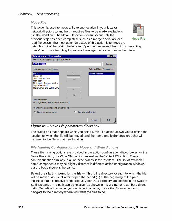
Chapter 6 — Auto Processing
110 Viper Vehicular Information Processing Software
Move File This action is used to move a file to one location in your local or network directory to another. It requires files to be made available to it in the workflow. The Move File action doesn’t occur until the previous step has been completed, such as a merge operation, or a read file action. The most common usage of this action is to move the data files out of the Watch folder after Viper has processed them, thus preventing from Viper from attempting to process them again at some point in the future.
Figure 81 – Move File parameters dialog box
The dialog box that appears when you edit a Move File action allows you to define the location to which the file will be moved, and the name and folder structures that will be given to the file in that new location.
File Naming Configuration for Move and Write Actions These file naming options are provided in the action configuration dialog boxes for the Move File action, the Write XML action, as well as the Write PRN action. These controls function similarly in all of these places in the interface. The list of available name components may be slightly different in different action configuration windows, but the basic theory is the same.
Select the starting point for the file — This is the directory location to which the file will be moved. As usual within Viper, the period (‘.’) at the beginning of the path indicates that it is relative to the default Viper Data directory, as defined in the System Settings panel. The path can be relative (as shown in Figure 81) or it can be a direct path. To define this value, you can type in a value, or use the Browse button to navigate to the directory where you want the files to go.

Available Processing Components
Viper Vehicular Information Processing Software 111
Available Name Components — These are pieces of information that are available within ADR data files and which can be added as part of the destination file name and path. Typically when moving data, Viper uses the site ID and station number as part of the file name, but any of these items can be added to the name by moving them from the left box in this window to the right box (‘Selected Name Components’). The single arrow buttons will move the selected item over to the other box. The double arrows will move all items in the list to the other box.
Selected Name Components — These are the items of meta-data that are currently selected to appear in the file’s new directory path. The items are added to the file path and name from the top of the list to the bottom. You can choose the order by how you place items in the list (new additions are added to the bottom of the list) or you can click and drag a name component up or down on the list. The ‘Original filename’ and the ‘Original extension’ components both includes the dot (‘.’) of the filename, so they are usually at the bottom of the list. Using the ‘Original Extension’ as the last item, allows you to change the file name to one of the other items (e.g. ‘Station, Date and ESN’) followed by the original extension. The items that appear above these last two items are used to create a set of subdirectories in your chosen file storage location. So choosing Selected Name Components equal to: Station ID, Site ID, Original Extension, will place the file in your selected folder as defined above, in a subdirectory named for the station ID, and the file will have the name <Site ID>.<original extension>.
Standard Long Name — This is the default filename given to an export or report file. The file will be named <SiteID>_<StationID>_<Datenumber>.<output format extension> for a report.
Sample File Name — This line displays the path and file name that will be given to a file when it is moved by this action.
If a file with the same name already exists — These radio buttons allow the operator to select what should be done if a file with the suggested name already exists in the suggested location on your drive or network server. The options are ‘Generate a new name’, which tells Viper to add a number to the end of the filename to make the file unique, or ‘Overwrite existing file’, which tells Viper to simply write the file with the name anyway, even though the previous file is being deleted in the process. Obviously, this latter option should be used with great care, and only when you are absolutely certain that you will not be overwriting unique and unrecoverable data.

Chapter 6 — Auto Processing
112 Viper Vehicular Information Processing Software
Read Binned Data File This action tells Viper to read through a data file. This is usually only performed just prior to using one of the Write actions (Write PRN, Write XML, Write TMG.) It requires a file input, such as a Watch folder and is usually followed by a Write action. It is also a very good idea on a Read action to have an error handling action as well, since it is possible for data files to be incomplete or corrupted. The Read action will only attempt to read in files that have a .bin filename extension.
Figure 82 – Read Binned Data File parameters dialog box
This action has no configurable options, even though there is a dialog box that appears when you double-click the action box. At present, there is nothing to configure, but parameters may be added here in future releases.

Available Processing Components
Viper Vehicular Information Processing Software 113
Sort Files by Data Type When multiple types of data may be arriving in the watch folder from field devices, this is often the key action in the first workflow you define. This action takes all of the files in a Watch folder and moves them to other folders, based on the types of files they are.
Figure 83 – Sort Files by Data Type parameters dialog box
Binned Data — This is the location that you want Viper to place binned data files. Viper identifies binned files by opening it up and reading the data. If the data is recognized as binned ADR data, then the file will be moved to this location. (If the file is sufficiently corrupted, it will fall through to the ‘Unrecognized’ type.) You can type in a value, or use the Browse button to navigate to the directory where you want the files to go. The default location is .\Processing\Bin.
PVR Data — This is the location where you want Viper to place PVR (‘per vehicle record’) files. Just as with binned data, Viper recognizes a PVR file by opening it up and recognizing the data as PVR data. If the file is a PVR data file, but is sufficiently corrupted, Viper will handle it as an ‘Unrecognized’ file.) To set this path, you can type in a value, or use the Browse button to navigate to the directory where you want the files to go. The default location is .\TOPS_Ready, since Viper does not usually perform any additional actions on these types of files.
Unrecognized or Invalid — The place where Viper should store files that are not clearly either binned data files or PVR data files. These are usually support files for the ADR hardware, such as log files, setup files, or configuration files, or they are data files that have been corrupted to a point where Viper cannot recognize them as valid BIN or PVR files. Again, you can type in a value, or use the Browse button to navigate to the directory where you want the files to go. The default location is .\TOPS_Ready, since Viper does not perform any additional actions on files of unknown type.
If file already exists — These radio buttons allow the operator to select what should be done if a file with the suggested name already exists in the suggested location on your drive or network server. The options are ‘Rename’, which tells Viper to add a number to the end of the filename to make the file unique, or ‘Overwrite’, which tells Viper to simply write the file with the name anyway, even though the previous file is

Chapter 6 — Auto Processing
114 Viper Vehicular Information Processing Software
being deleted in the process. Obviously, this latter option should be used with great care, and only when you are absolutely certain that you will not be overwriting unique and unrecoverable data.
Write PRN This action allows Viper to save ADR binned data, which arrives in a binary format, to the older, but easier to read, ASCII-formatted PRN format. A Write PRN command must be preceded by a Read Bin file action, so that Viper has the available data at hand.
Figure 84 – Write PRN parameters dialog box
The configuration options for the Write PRN action are basically the same as those for a Move file command, based on file location and the naming convention you wish to use on the PRN file output. A discussion of the naming options is provided in “File Naming Configuration for Move and Write Actions” on page 110.

Available Processing Components
Viper Vehicular Information Processing Software 115
Write XML This action allows Viper to save ADR binned data, which arrives in a binary format, to an XML file format. A Write XML command must be preceded by a Read Bin file action, so that Viper has the available data at hand.
Figure 85 – Write XML parameters dialog box
The configuration options for the Write XML action are basically the same as those for the Move file or the Write PRN actions, based on file location and the naming convention you wish to use on the XML file output. A discussion of the naming options is provided in “File Naming Configuration for Move and Write Actions” on page 110.

Chapter 6 — Auto Processing
116 Viper Vehicular Information Processing Software
Write TMG This action creates the appropriate TMG records, based on the configuration in each device. Available export files include the Station, Volume, Class and Weight records. Because the data files are typically processed as they arrive, the new data will be appended to any existing output. As a result, the TMG export files for a given time span will always be as complete as possible.
Because much of the TMG information must be configured on a per-device basis. For a successful TMG export, the following information (at a minimum) must be available for any device to be processed for TMG data submission:
On the Identification tab: County State
On the Site tab: Site ID (must match what will appear in files from that device) Station Number (must match what will appear in files from that device) Number of arrays (should match what will appear in files from that device) At least one array must have a check-mark in the TMG Volume, TMG Class or
TMG Weight columns.
On the TMG tab:
TMG Station identification
Functional class
In addition, certain application-wide TMG options (for example the export filename prefix) are configured using the TMG Export tab in the main interface.

Available Processing Components
Viper Vehicular Information Processing Software 117
Generate Report The Generate Report action takes a binned data file as the input and generates a pre-formatted report as the output. The output can be written as a PDF file, as an Excel spreadsheet, or as a text file. And the naming of the report has the same naming options as the Write PRN and Write XML actions.
The type of report generated depends on the report definition file you select. Viper 1.0 has four report definitions included: Class, Class by Channel, Speed, and Volume. More details about generating reports and the possibilities of custom reports are discussed in “Generating a Viper Report” on page 174.
Figure 86 – Generate Report parameters dialog box
Report definition file — Report output is defined in Viper by binary .rpt files. There are four reports available in this release of Viper. Select the type of report you want run on the data.

Chapter 6 — Auto Processing
118 Viper Vehicular Information Processing Software
Report output format — This is where you can select the type of report file format that will be generated. The options are a PDF file (.pdf), a Microsoft Excel™ spreadsheet file (.xls), or a comma-delimited text file (.txt).
A discussion of the naming options is provided in “File Naming Configuration for Move and Write Actions” on page 110.

Creating an Automatic Processing Plan
Viper Vehicular Information Processing Software 119
CREATING AN AUTOMATIC PROCESSING PLAN The topics in this section describe the standard workflow available in Viper when it is installed, and describes the configuration options that are available for each of the types of workflow action.
Default Configuration When you first open the Viper Automatic Processing panel, this is the workflow that will be visible. This is a standard workflow that separates incoming binned data from PVR data files and other files that Viper cannot process. It then reads the binned data and if there are no problems with the data, it generates a PRN output file with a standardized file name.
Figure 87 – Default auto-processing configuration
These are the parts of the above auto-processing plan:
1. Workflow 1
2. Workflow 2
3. Watch folder for first workflow
4. End of the first workflow
5. Watch folder for second workflow
6. End of the second workflow
3 1
2
4
5
6

Chapter 6 — Auto Processing
120 Viper Vehicular Information Processing Software
Figure 88 – First workflow of the default configuration
7. Watch folder for the first workflow. Looks for files in the Incoming folder that is located in your standard Viper data folder, as defined in System Settings.
8. End of the first workflow. This step sorts the files that come into the Incoming folder. It places binned data files into another folder (the Processing\Bin folder located in your standard Viper data folder) where they will be picked up by the second workflow. PVR data files and any files Viper doesn’t recognize as data (often ADR log files) into a TOPS_Ready folder, where they can be handled by TOPS or some other data management tool.
Figure 89 – Second workflow of the default configuration
9. This is the watch folder that starts the second workflow. This step watches the folder where the binned data was placed in the first workflow. Note that even though this workflow is listed below the one above, it does not need to wait for the first workflow. Each workflow functions independently, and each begins to run as soon as it detects a fully written file in the watch location. In most
7
8
9
11
12
14
13
10

Creating an Automatic Processing Plan
Viper Vehicular Information Processing Software 121
situations, the second workflow will start as a result of the output generated by the first workflow. But if a binned data file is placed in the .\Processing\Bin folder from some other source, the plan will go ahead and process the data even though it didn’t arrive via the first workflow.
10. This step tells Viper to read the contents of the binned data file into memory.
11. If there is a problem reading the binned data, this step sends the file to a Problem folder tagged with the site ID of the data source.
12. If there are no problems reading the contents of the binned data file, Viper will write the resulting data as a PRN file, saved to the Output\PRN-Files\ folder in Viper’s default data directory. The file will be tagged with the Site ID, Station ID, and a date-based filename.
13. If there is a problem generating the output PRN file in the above location, the data file will instead be stored in an alternative location (.\Data\Problem\) and tagged with the Site ID and Station name of the data source.
14. If, however, everything goes well with the PRN file generation, finally, the Viper service will move the original binned data file form its location in the Incoming folder to the same ./TOPS_Ready/ folder where the PVR and unrecognized files were moved in step 4. This is the end of the second workflow in this auto-processing plan.

Chapter 6 — Auto Processing
122 Viper Vehicular Information Processing Software
Error Handling It is important to consider what happens to your auto-processing plan when things don’t go exactly as planned. Viper has the capability to allow you to determine what should happen when an error is encountered. An error could be a corrupted data file, or the expected file storage location being unavailable (for instance, if a network server goes down). Any action in the auto-processing environment that has the possibility of an error condition has a connection point to use to deal with such an error. The yellow connection point on the right side of an action box is where you can connect a step ‘in case something goes wrong’.
Figure 90 – Error handling task option
But what exactly happens when an error condition is detected. First, realize that Viper only detects a Boolean state of error detection; either there is an error or there isn’t. Whether the file data is incomplete or the user doesn’t have operating system rights to the defined output directory, Viper will handle the error situation in the same way (as you have defined it.)
If you have defined a ‘Move’ file action as an error handling step attached to a step that creates an output, such as a Write PRN, Write PVR, Write TGB, or Create Report, as soon as an error is detected, the effort to create the output stops and the source file of the data is sent to the defined ‘Move to’ location.
If NO error handling option is defined for such a step (it is an optional item, after all) then Viper will do something different when an error is detected. Since Viper is unable to move past the error, it will simply leave the source file where it found it and note that it generated an error. Viper will not attempt to handle the file again until the Auto-processing server is restarted. However it will go ahead and attempt to handle any new files that show up in the Watch folder.
Note Sending a new auto-processing plan to the server is equivalent to restarting the Auto-processing service.
We highly recommend that you do create error handlers for all of the steps where it is available, to avoid having unhandled data files piling up in the Watch folder. Such files will also cause a glut of processing activity whenever the Auto-Processing service restarts, as the service attempts to reprocess all of the error-generating data files. The default plan description in the previous section shows a typical method of handling error conditions: simply move the data file to a ‘problem’ folder and tag it with the device and location information of where it was generated.
Error handling connection

Creating an Automatic Processing Plan
Viper Vehicular Information Processing Software 123
Setting a Watch Folder Trigger The Watch Folder trigger is typically used as a starting point for an automatic processing operation. It monitors the specified folder for new or modified files. A short time (typically 5 seconds) after the last time a file is changed information about the file will be fed to the next task in the configured process.
Figure 91 – Configuring the watched folder
Merging ADR Binned data One component of Viper is a mechanism to merge ADR binned data - that is to generate a single file containing information from multiple initial units. Some examples of when this functionality is useful would be:
When geographical constraints at a site require multiple units to collect the information.
When a temporary unit is used to collect data normally gathered by another device (e.g. due to sensor failure).
Configuring a merged site when sample data from the source sites is available The easiest way to configure a merge operation is by having sample data files available from all source sites. The following procedure describes how you would perform this operation.
1. Launch the Viper front end
2. Select the Automatic Processing tool
3. If no merge operation is currently selected, drag the merge icon from the right hand panel into the main area of the form.
4. Double click on the merge operation now in the main area to open the merge configuration window.
5. The merge configuration window includes options relating to the maximum age of the files, and the initial output folders as well as the merged site configuration. Adjust those settings if desired.

Chapter 6 — Auto Processing
124 Viper Vehicular Information Processing Software
6. Click on the Add new merged site button. The Create Merge Site Wizard will appear.
7. Choose I have files available from all of the source sites to use as a starting point.
8. Click Next.
9. Click Browse, and select a file from the first site.
10. Click Next.
11. If there is another source site, make sure Yes, there is at least one more source site selected and repeat the previous three steps for each additional source site, otherwise select the No, files from all the source sites have been added option and click Next.
12. Enter a site ID and station number for the merged data.
13. Click Next.
14. Confirm that the new site details are correct, and click Finish.
15. If desired, the merged data settings can be modified after initial creation in the same way that they can be specified if sample data from the source sites is not available. If no modifications are required, click the OK button.
Note Before the merge operation can be fully activated, it must be connected to some other part of the automated processing mechanism.
Configuring a merged site when sample data from the source sites is Not Available While it is significantly easier to configure the data merge operation when sample data from the source sites is available, it is also possible to configure a merge operation without that information. Before you can do so, you will need to know the following:
The number of arrays for each of the source sites.
The number of channels of data recorded at each of the source sites.
The desired number of arrays in the merged data.
The desired number of channels in the merged data.
How each array from the source data is mapped to an array in the merged data.
How each channel from the source data is mapped to an array in the merged data.

Creating an Automatic Processing Plan
Viper Vehicular Information Processing Software 125
Note In most cases the number of channels is the same as the number of arrays, but the number of channels may be greater depending on the data being collected. For example: If a single lane sees vehicle traffic in two directions, and the sensor array can differentiate between the two directions, it would be most desirable to configure the field device to record each direction separately. This would result in a scenario where there is only one array, but two channels
To configure a merged site manually, you will need to do the following:
1. Launch the Viper front end
2. Select the Automatic Processing tool
3. If no merge operation is currently selected, drag the merge icon from the right hand panel into the main area of the form.
4. Double click on the merge operation now in the main area to open the merge configuration window.
5. The merge configuration window includes options relating to the maximum age of the files, and the initial output folders as well as the merged site configuration. Adjust those settings if desired.
6. Click on the Add new merged site button. The Create Merge Site Wizard will appear.
7. Choose I do not have files available, or wish to configure the virtual site manually.
8. Click Next.
9. Enter a site ID and station number for the merged data.
10. Click Next.
11. Click Finish.
12. Set the Number of arrays in merged site field to the appropriate value. (In most cases, this will be the sum of the number of arrays in the source sites).
13. Set the Number of channels in merged site field to the appropriate value. (In most cases, this will be the sum of the number of channels in the source sites).
14. Click the Add new source site button
15. In the Current source site settings area, set the Site ID and Station number fields to the appropriate source values.
16. Set the Number of arrays in source site and Number of channels in source site fields to the appropriate values.
17. In the Source to destination array mapping, set the desired destination array for all source arrays.

Chapter 6 — Auto Processing
126 Viper Vehicular Information Processing Software
18. In the Source to destination channel mapping, set the desired destination channel for all source channels.
19. Repeat the previous 5 steps for each additional source site.
20. Click OK to save the settings.

Creating an Automatic Processing Plan
Viper Vehicular Information Processing Software 127
Example: Desired Merge Operation Using Manual Configuration As mentioned earlier, a good reason for wanting to merge data is that a single physical unit cannot (for whatever reason) collect information from all lanes. The image below shows an example. The yellow boxes represent the first source unit, the cyan ones the second unit, and the red boxes the third. Since the information collected is from the same road, the desired operation is to create a virtual site (the green one) containing the information from the three real sites.
Figure 92 – Three source sites, and how they map to a single destination site

Chapter 6 — Auto Processing
128 Viper Vehicular Information Processing Software
The first step is to define the virtual site, which will have 8 arrays and 8 channels, plus the first source site. When you have done so, this is what you will see on the merge configuration user interface:
Figure 93 – Partial configuration - Merged site defines and first source site added
The second source site should then be added. As you can see from the initial diagram, the arrays (and channels) from the second source site are mapped in reverse order to the last three arrays (and channels) in the output site.
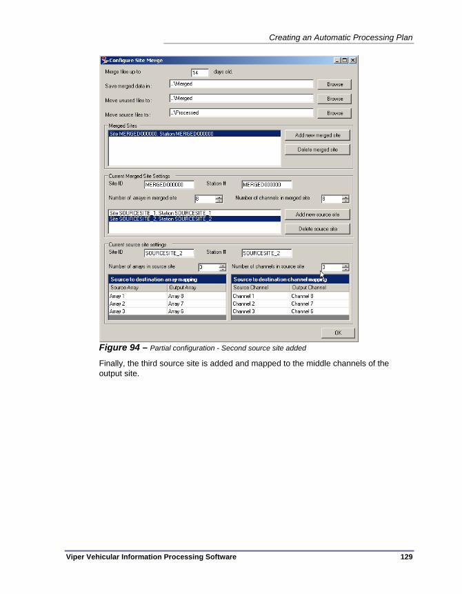
Creating an Automatic Processing Plan
Viper Vehicular Information Processing Software 129
Figure 94 – Partial configuration - Second source site added
Finally, the third source site is added and mapped to the middle channels of the output site.
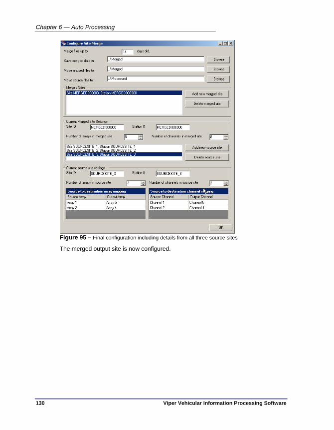
Chapter 6 — Auto Processing
130 Viper Vehicular Information Processing Software
Figure 95 – Final configuration including details from all three source sites
The merged output site is now configured.

Creating an Automatic Processing Plan
Viper Vehicular Information Processing Software 131
Sorting Data Files by Type Often, it is desirable to perform different processing based on the type of data - for example per-vehicle record data typically needs to be exported in a different format to binned data.
This task allows users to sort data, based on the file contents, into different folders.
Figure 96 – Configuring the Sort Files By Type operation
To change the folder into which a specific type of file will be placed, simply type the folder name, or click the Browse button next to the type of data you are interested in.
Adjusting Binned Data for Daylight Savings Time Changes The ADR 6000 processes daylight saving time changes in a different way to the ADR 1000/2000/3000. This task manipulates the raw data in such a way that the bin data files can subsequently be read by other processing tools which would have rejected some of the ADR 6000 data believing it to be invalid.
Figure 97 – Configuration options for the Daylight Savings Adjustment operation
The operation has two configurable settings:
A folder in which to store a copy of any modified files made before any adjustments are made.
A folder in which adjusted files, or any files not requiring modification will be placed.
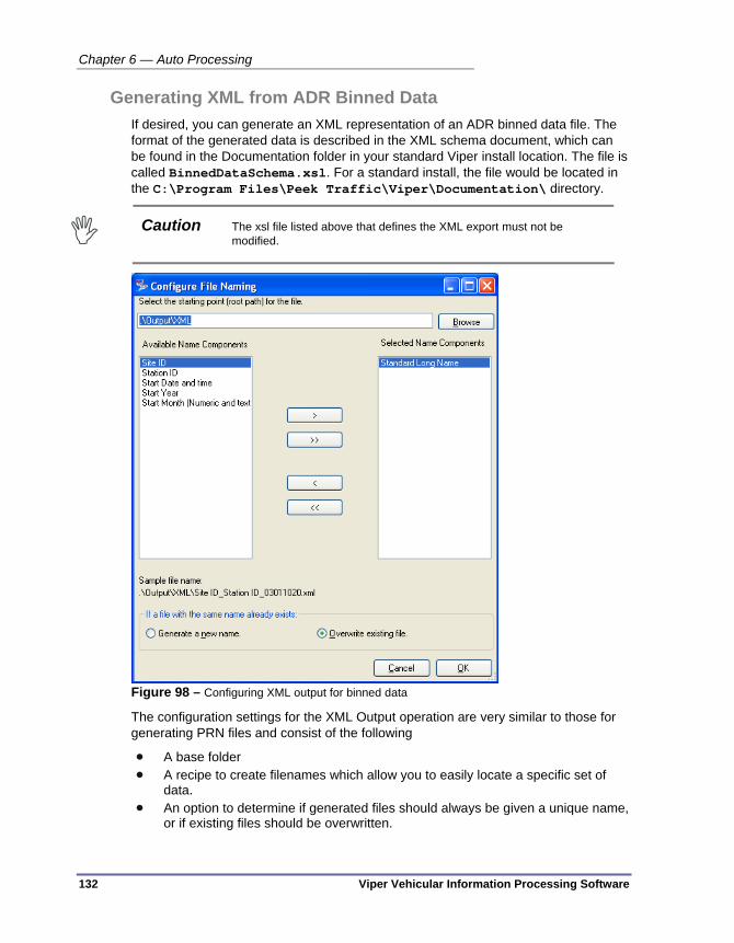
Chapter 6 — Auto Processing
132 Viper Vehicular Information Processing Software
Generating XML from ADR Binned Data If desired, you can generate an XML representation of an ADR binned data file. The format of the generated data is described in the XML schema document, which can be found in the Documentation folder in your standard Viper install location. The file is called BinnedDataSchema.xsl. For a standard install, the file would be located in the C:\Program Files\Peek Traffic\Viper\Documentation\ directory.
Caution The xsl file listed above that defines the XML export must not be
modified.
Figure 98 – Configuring XML output for binned data
The configuration settings for the XML Output operation are very similar to those for generating PRN files and consist of the following
A base folder A recipe to create filenames which allow you to easily locate a specific set of
data. An option to determine if generated files should always be given a unique name,
or if existing files should be overwritten.

Creating an Automatic Processing Plan
Viper Vehicular Information Processing Software 133
Note Unlike the PRN output where overwriting existing files can easily lead to lost data, because the XML output contains information for all studies data will only be overwritten if two devices are configured identically, or the naming recipe does not include elements that ensure a unique name
Move File Task It is often helpful to sort data files based on their contents (especially for archiving purposes). The Move File operation allows you to accomplish this.
Figure 99 – Configuring the Move File operation
The configuration settings for the Move File operation are very similar to those for generating PRN files and consist of the following:
A base folder
A recipe to create filenames which allow you to easily locate a specific set of data.
An option to determine if generated files should always be given a unique name, or if existing files should be overwritten.

Chapter 6 — Auto Processing
134 Viper Vehicular Information Processing Software
Generating a Report from Binned Data The report generation operation in Viper v1.0 is a proof-of-concept implementation, and is almost certainly too limited in scope for significant use. A specific limitation is that for multiple-study data, reports can only be generated for the first study.
Figure 100 – Configuring the Binned Data Reporting operation
The most significant configuration options are as follows The Report definition file is an rpt file which contains the report layout etc. The Report output format which allows you to select the format of the
generated file – for example PRN, or Excel compatible.
The remaining options for the Generate Report operation are very similar to those for generating PRN files and consist of the following: A base folder A recipe to create filenames which allow you to easily locate a specific report.
An option to determine if generated files should always be given a unique name, or if existing files should be overwritten.

Viper Vehicular Information Processing Software 135
Chapter 7 — Scheduling Activity
This chapter discusses how to schedule regular or one-off future activity in Viper. The following topics are discussed in detail in this chapter:
• An overview of scheduling activity in Viper, on page 136.
• An introduction to the Scheduling interface, on page 137.
• How to Add a scheduled task to Viper, on page 146.
• How to Edit a schedule, on page 147.
• How to Monitor scheduled operation, on page 147.
• How to Delete a scheduled activity, on page 148.

Chapter 7 — Scheduling Activity
136 Viper Vehicular Information Processing Software
OVERVIEW Scheduled events are used by Viper primarily to handle the retrieval of data from ADR hardware at pre-determined times. Scheduled events are managed and triggered by a service running in the background on your Viper system. The service is called the SchedulerService.exe and it is managed by the Windows services environment, which means that when the system is restarted or it suffers a brown-out or some other problem, the Windows services manager will automatically restart the Viper Scheduler.
The Viper front-end interface includes a panel for managing scheduled events. The Scheduled Tasks panel is very similar to the Devices and Communications Channels panels in how it is navigated and how one managed individual tasks in a list.
Figure 101 – Scheduled Tasks panel of the Viper front-end interface
Although other types of scheduled tasks may be available in the future, in Viper v1.0 the only type of task that is available is polling for device data.
The data files that are retrieved by Viper are placed in the incoming files folder. The location for this is set on the System Settings panel, under the ‘Download path for automatically collected data files’ field. The default location is in the .\Incoming folder just beneath the root path directory for Viper data.
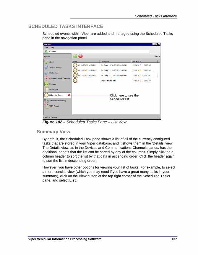
Scheduled Tasks Interface
Viper Vehicular Information Processing Software 137
SCHEDULED TASKS INTERFACE Scheduled events within Viper are added and managed using the Scheduled Tasks pane in the navigation panel.
Figure 102 – Scheduled Tasks Pane – List view
Summary View By default, the Scheduled Task pane shows a list of all of the currently configured tasks that are stored in your Viper database, and it shows them in the ‘Details’ view. The Details view, as in the Devices and Communications Channels panes, has the additional benefit that the list can be sorted by any of the columns. Simply click on a column header to sort the list by that data in ascending order. Click the header again to sort the list in descending order.
However, you have other options for viewing your list of tasks. For example, to select a more concise view (which you may need if you have a great many tasks in your summary), click on the View button at the top right corner of the Scheduled Tasks pane, and select List:
Click here to see the Scheduler list

Chapter 7 — Scheduling Activity
138 Viper Vehicular Information Processing Software
Figure 103 – Scheduled Tasks Pane – List view
The most detailed view is the Tile view, as shown here:
Figure 104 – Scheduled Tasks pane – Tiled view

Scheduled Tasks Interface
Viper Vehicular Information Processing Software 139
Every version of the Scheduled Tasks - Summary View has a pair of buttons in the top left corner that allow the operator to create a new scheduled task in the database and to delete one or more selected tasks from the database. (Refer to Figure 30.)
Figure 105 – Add and Delete buttons in Scheduled Tasks-Summary pane
Add a task
Delete one or more selected tasks
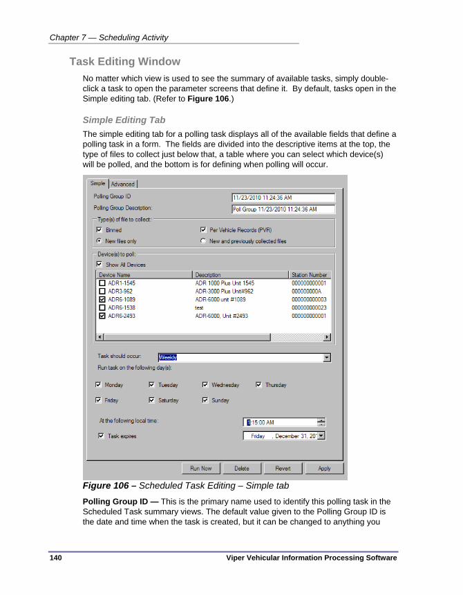
Chapter 7 — Scheduling Activity
140 Viper Vehicular Information Processing Software
Task Editing Window No matter which view is used to see the summary of available tasks, simply double-click a task to open the parameter screens that define it. By default, tasks open in the Simple editing tab. (Refer to Figure 106.)
Simple Editing Tab The simple editing tab for a polling task displays all of the available fields that define a polling task in a form. The fields are divided into the descriptive items at the top, the type of files to collect just below that, a table where you can select which device(s) will be polled, and the bottom is for defining when polling will occur.
Figure 106 – Scheduled Task Editing – Simple tab
Polling Group ID — This is the primary name used to identify this polling task in the Scheduled Task summary views. The default value given to the Polling Group ID is the date and time when the task is created, but it can be changed to anything you
Scheduled Tasks Interface
Viper Vehicular Information Processing Software 141
want. We’d recommend that you keep it short and descriptive so it is easy to see in the various summary lists.
Polling Group Description — A secondary description field for the polling task. This field is displayed in the Details and Tile summary views of the Scheduled Tasks pane.
Types of Files to Collect (Binned/PVR) — These two checkboxes tell the scheduler to retrieve either binned data files, PVR data files, or both.
Types of Files to Collect (New files/New and previously collected files) — This pair of radio buttons tells the polling process to retrieve only new files, or all files of the selected types. ADR-1000, 2000 and 3000 devices keep track of this information for us, however ADR-6000 do not natively track whether a file has been retrieved or not. So for ADR-6000s, the Viper auto-polling service keeps track of this information, using the Devices Only collect files newer than field. (The parameter appears on the Miscellaneous tab in the Devices panel, as shown on page 84.)
Devices to Poll — This table allows the operator to select which devices will be polled as part of this task. Checks in the first column indicate that the device in question will be polled. The Show All Devices button toggles the list between showing all of the devices (including those that are not currently selected for polling) and showing only those that have been selected. The table can be sorted by column by simply clicking on the column header. Clicking the same header again will reverse the sort order. (ascending to descending order, for instance)
Task should occur — This drop down box is used to select whether this is a daily, weekly, or monthly task. Note that the Daily and Monthly options only call for the polling to be one time during the time frame, but a Weekly task can occur on one or many of the days in a week. This means that a Weekly task could be configured to be almost Daily, but to avoid certain days, such as Saturday and Sunday.
Run tasks on the following day(s) — This list of checkboxes only appears when the ‘Tasks should occur’ period is set to Weekly. One or more days of the week can be specified for polling activities. Each day that is checked will have a polling event.
When the day of the Month is — This parameter only appears when the ‘Task should occur’ period is set to Monthly. This is the date of the month when the devices will be polled. Note that a selection of 29,30, or 31 will be skipped on months that don’t have that number of days.
At the following local time — This is the time that the polling will occur, as perceived by the polling computer (i.e. the Viper machine.) Time is edited by selecting the portion of the time HOURS, MINUTES, SECONDS, or AM/PM and then either typing in a number or using the up and down arrows to change the value.
Task expires — This checkbox determines whether there is an ‘end date’ for the autopolling task. If unchecked, which is the default state, the task will repeat forever. If checked, the date field at right becomes available, and you can set the date when the task will turn OFF. The task will be halted and REMOVED FROM THE LIST at the end (11:59:59 pm) of the selected day.

Chapter 7 — Scheduling Activity
142 Viper Vehicular Information Processing Software
Run Now — This button takes the currently visible parameter settings and performs the equivalent polling operation immediately. This is one of the few places where the Viper front-end interface actually functions in an interactive mode. It should be noted that a scheduled task triggered via the "Run Now" button runs in the context of the current interactive user, which will typically be different from the context used by the system service. As a result, some things may not operate as part of a "Run Now" operation, but will work when run by the Scheduler, or vice versa.
Delete — Selecting Delete will tell Viper to discard the currently selected task from the SchedulerService. Before the software will remove the data stored for this device, it will ask the operator to verify that he or she actually does wish to remove the task. There is no undo function to recover a task, should one delete it accidentally, however if a task is part of a recent archive, the task could be recovered that way, with the understanding that all other changes that were made after that archive was performed will be lost when the archived copy is restored.
Revert — The Revert button can be used to restore any settings that were changed since the operator opened the window, as long as the settings haven’t been Applied to the database. This is true across tabs within the Scheduled Tasks pane. So if changes are made to the Advanced and Simple tabs on this task, and the Apply button has yet to be pressed, selecting Revert will restore all of the previous values to the Scheduled Tasks tabs.
Apply — The Apply button is used to store any changes that have been made to the scheduled task parameters on any of the tabs. The parameters are stored to the Viper database and sent to the SchedulerService.
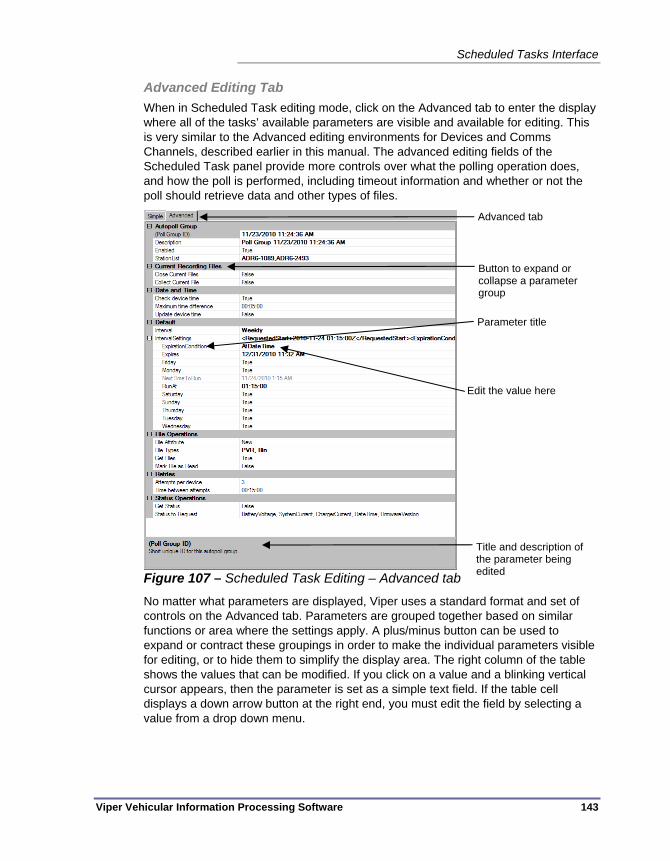
Scheduled Tasks Interface
Viper Vehicular Information Processing Software 143
Advanced Editing Tab When in Scheduled Task editing mode, click on the Advanced tab to enter the display where all of the tasks’ available parameters are visible and available for editing. This is very similar to the Advanced editing environments for Devices and Comms Channels, described earlier in this manual. The advanced editing fields of the Scheduled Task panel provide more controls over what the polling operation does, and how the poll is performed, including timeout information and whether or not the poll should retrieve data and other types of files.
Figure 107 – Scheduled Task Editing – Advanced tab
No matter what parameters are displayed, Viper uses a standard format and set of controls on the Advanced tab. Parameters are grouped together based on similar functions or area where the settings apply. A plus/minus button can be used to expand or contract these groupings in order to make the individual parameters visible for editing, or to hide them to simplify the display area. The right column of the table shows the values that can be modified. If you click on a value and a blinking vertical cursor appears, then the parameter is set as a simple text field. If the table cell displays a down arrow button at the right end, you must edit the field by selecting a value from a drop down menu.
Advanced tab
Button to expand or collapse a parameter group
Title and description of the parameter being edited
Parameter title
Edit the value here

Chapter 7 — Scheduling Activity
144 Viper Vehicular Information Processing Software
Figure 108 – Advanced tab of the Channel pane for a Serial channel
Some additional notes about the Advanced Scheduled Task editing tab:
Enabled – This parameter is not shown on the Simple tab. This field can be used to configure a polling task that is used occasionally, but not always. The Enabled field can be changed to False in order to keep the task programming in the list, but to not have it run at its regularly scheduled times.
Current Recording Files — These two parameters tell the polling service what to do to an ADR that is currently recording data at the time of the polling call.

Scheduled Tasks Interface
Viper Vehicular Information Processing Software 145
These tell the service whether to close the currently open file, and whether or not it should retrieve the current (incomplete) file back to Viper. By default, these values are both False.
Date and Time — These parameters are used to let the Scheduler service perform time synchronization functions on the ADR devices. These three parameters tell the scheduler whether or not to check the device’s time (default = False), if it checks the time, what difference between the device’s time and the Viper computer’s time will cause a time sync on the device (default = 5 minutes), and the final parameter is whether or not to update (synchronize) the device’s time if it exceeds the difference (default is False). If the last item is left at False, then the time difference will simply be noted in the Viper log.
Interval Settings — The displayed value is a result of all of the settings below it in the collapsed portion of the parameter tree. The value cannot be edited directly on this line.
Expires — This date and time will only be used if the ExpirationCondition is set to ‘AtDateTime’.
File Types — The checklist under this parameter has a few more options that the similar control on the Simple tab. In addition to Bin and PVR files, here you can tell the poll to request Event files, Log files, Setup files, or Other (any other visible files) from the ADRs.
Get Files — This option allows you to turn off file retrieval from a polling event. One might use this to perform a time sync only task by setting this value to True with the Update device time parameter (above, under ‘Date and Time’) also set to True. A similar type of non-file-retrieval task would be to get ADR status information without retrieval data files, using the controls under Status Operations (below).
Retries — The default for polling events is three tries, with 15 minutes between attempts. These values can be modified here on the Advanced tab.
Status Operations — These controls can be used to request status information from the polled devices. If Get Status is set to True, then the following pieces of information can be retrieved from an ADR:
Battery Voltage
System Current
Charge Current
Date and Time values
Current firmware version on the device
These values are selected using a set of checkboxes under Status to Request.

Chapter 7 — Scheduling Activity
146 Viper Vehicular Information Processing Software
ADDING A SCHEDULED TASK If desired, the software can be configured to automatically retrieve data from one or more data collection devices. This is accomplished by using the Scheduler component.
To add an automatic polling task:
1. Launch the Viper application (if it is not already running).
2. On the left hand side of the main form, you will see a button labeled Scheduled Tasks. Click on it.
3. The Scheduled Tasks area will expand, showing you a summary of the currently configured tasks. Just below the Summary button is one labeled Add New Task. Click on the Add New Task button.
4. Select the Autopoll device(s) task from the available tasks.
5. Set the Polling group ID to Polling Group 1 (or whatever you want the polling group to be called).
6. Set the Polling group description to something descriptive. This it the text which will appear in the GUI for the group.
7. Make sure that the appropriate box(es) are checked to indicate which type(s) of data are included in the polling operation.
8. In the Devices to Poll section, make sure there is a check mark next to the device(s) you wish to poll.
9. Set how frequently you would like the polling task to occur. (Daily, Weekly or Monthly)
10. Set the time at which the task should occur.
11. Click OK to add the task.
12. [Optional] If desired, you can test any task (including the one you just created) by doing the following:
a.) Selecting the task and click the Run Now button below the task settings.
b.) A new window will open showing the task progress.
c.) Click Close once the task is complete. (In the case of the automatic polling task this will be some time - about 10 - 15 seconds - after the "Poll Group: Polling group 1 finished" message appears because of the generation of the user-friendly polling report.)
Note Because the scheduled tasks are intended to run unattended there may be some situations – for example when downloading large files, or generating reports - when there are no new messages for a significant time.

Modifying a Scheduled Task
Viper Vehicular Information Processing Software 147
MODIFYING A SCHEDULED TASK To edit an existing polling task:
1. Launch the Viper application (if it is not already running).
2. On the left hand side of the main form, you will see a button labeled Scheduled Tasks. Click on it.
3. The Scheduled Tasks area will expand, showing you a summary of the currently configured tasks. Double-click on the task you wish to modify.
4. To modify the device list, the name or description of the task, or the dates and times to perform the polling operation, make the changes on the Simple tab.
5. If you wish to modify the list of files that will be retrieved, to disable the polling event, to using polling to perform time sync or status checking operations, or to modify how many times the polling is attempted, switch to the Advanced tab.
6. Make all of the desired changes to the task.
7. Once satisfied with the changes, click the Apply button at the bottom of the window to save the changes. This will immediately send the new parameters to the SchedulerService in Windows.
Note Or you have the option to Revert all of the settings to the values you found when you first opened the task editing window by using the Revert button at the bottom of the window.
This completes the modification of the task.
MONITORING A SCHEDULED TASK Monitoring of selected tasks cannot be performed directly within Viper. The method to determine if tasks are being performed is to check for the resulting retrieved files in the Viper incoming files folder. The location for this is set on the System Settings panel, under the ‘Download path for automatically collected data files’ field. The default location is in the Incoming folder just beneath the root path directory for Viper data. If you are using the installed defaults for these parameters, the data files will appear in this folder for Windows XP:
C:\Documents and Settings\All Users\Application Data\Peek Traffic\Viper\Incoming\
Under Windows 7, the files will appear in:
C:\ProgramData\Peek Traffic\Viper\Incoming\
Although, if the auto-processing plan set up within Viper is set to move incoming data files after processing them, this may not be where you will find the resulting data files from a polling event. In such cases, one would need to check the currently running auto-processing workflows to see where files will end up on the system or network drives.

Chapter 7 — Scheduling Activity
148 Viper Vehicular Information Processing Software
DELETING A SCHEDULED TASK Follow these steps to delete an existing task from your Viper scheduler service:
1. Open the Viper front end.
2. Click on the Scheduled Tasks button in the navigation bar.
3. In the list of existing tasks, select the item you wish to remove.
4. Click the Delete button in the top left corner of the Scheduled Task panel.
Figure 109 – Delete button at the top of the Scheduled Task pane
5. If you are sure you do wish to delete the selected task, select Yes in the verification dialog box.
Figure 110 – Verify that you wish to delete the task

Viper Vehicular Information Processing Software 149
Chapter 8 — Exporting Data
This chapter provides a discussion of the exporting and reporting features of Viper, including details on creating the various types of exports and using the Viper report generator. The following topics are discussed in detail in this chapter:
• An overview of the reporting and export capabilities of Viper, on page 150.
• The process of creating a PRN export, on page 151.
• The process of creating an XML export, on page 160.
• The process of creating a TMG export, on page 166.
• Using Viper’s own Reporting tool to generate a report file, on page 174.

Chapter 8 — Exporting Data
150 Viper Vehicular Information Processing Software
OVERVIEW – EXPORTING DATA FROM VIPER Although Viper does have some limited interactive capabilities when dealing with the ADR hardware, and it can do some limited things with the data itself, its primary purpose is as an automatic data retrieval and pass through package. It takes data from the field and presents it to your other data processing applications in a predictable manner. These output files are generated using the export and reporting features of Viper’s auto-processing module.
In this section, we walk through the configuration options and steps required to generate the various types of data output capabilities of Viper. For binned data, which is gathered from ADR hardware as binary information, the output can be one or more of the following:
Renamed bin files (This is a simple ‘Move’ operation)
ASCII text based PRN files
Standardized XML data files
U.S. Federal Highway Administration compliant TMG data reports
Reports in PDF format
Reports in Microsoft Excel format
With the exception of the first option listed above (Renamed bin files, which is technically a Move operation rather than an Export or Report), all of the ultimate data destinations mentioned here are accomplished by adding either an Export or a Report action block to your active Auto-processing plan.
Exports/Reports in Viper are not generated interactively. They are always generated as the result of data processing by the Auto-Processing service.
Generating a PRN Export
Viper Vehicular Information Processing Software 151
GENERATING A PRN EXPORT The PRN Export process converts the incoming binned data into PRN files in a location of your choosing. The operator has the option of selecting a custom naming convention for the output files.
The process of creating a PRN export has these steps:
1. Add the Write PRN action to the Automatic Processing configuration (See “Adding the Write PRN Action”, on page 151)
2. Define the naming convention to be used for the PRN files (See “Setting PRN File Names”, on page 155)
3. Set the directionality and units parameters in the PRN Export panel (See “Setting PRN Export Parameters”, on page 157)
4. Activate the Auto-processing plan (See “Activating the PRN Export Plan”, on page 159)
Adding the Write PRN Action To begin the process of generating a PRN export, we first need to add an action to your auto-processing plan. Follow these steps to add the action:
1. Open the Auto-processing panel by selecting Automatic Processing in the navigation panel of Viper’s front end interface.
2. The rest of the processing plan should be in place, namely setting the Watch folder for incoming Bin files, and any file Move, Sorting, or renaming operations. The panel will open showing the plan that is currently running in the Auto-processing service. If you wish to edit the current plan, go to step 3 now, however if you wish to edit a plan that is stored in a file, go to the File menu and select Load from file. Open the .psm file that contains the auto-processing plan you wish to modify.
3. To add a Write PRN action, you will need to have a Watch folder that will receive Binned data files, and you will need a workflow in place that will read the binned data file into Viper. Figure 111 shows a workflow with a Read Binned data file operation (with its associated error handling action connected at the right connect point.) You can see that the Read action requires a next step, as indicated by the red connection dot at its bottom. This is where we will connect the Write PRN action.
Note The Write PRN action is typically added right below a Read Bin action, however it can also be placed beneath a Write XML action, thus allowing both export actions to follow from a single Read Bin action.

Chapter 8 — Exporting Data
152 Viper Vehicular Information Processing Software
Figure 111 – Auto-processing plan ready to receive a PRN export
4. In the Action library, select the Write PRN action icon. We want to place the next action box just below our Read file action.
Figure 112 – Selecting the Write PRN action in the Action library
Click and drag the icon to the place you want the box to appear and release the mouse button. You may need to click and drag the box to position it exactly where you wish it to be. (See Figure 113.)

Generating a PRN Export
Viper Vehicular Information Processing Software 153
Figure 113 – Placing the Write PRN action
5. Next, we must connect the output connection point of the Read Binned data action to the top connection point of the Write PRN action box.
Figure 114 – Connecting to the Write PRN action
6. We need to add an error handling action to the right side of the Write PRN box, in case the attempt to create the export results in an error (corrupted data, incorrect type of data file, etc.) One way to do this is just to move the source file to a ‘problem files’ directory.
Figure 115 – Adding an error handling action to Write PRN

Chapter 8 — Exporting Data
154 Viper Vehicular Information Processing Software
7. Finally, adding a Move action to handle files after the PRN export has been generated – This will prevent the auto-processing service from attempting to process the same bin files into duplicate PRN files if the service is restarted.
Figure 116 – Adding a final Move action to the PRN Export flow
Now that we’ve added the Write PRN action to the workflow, we’ll need to set up how it names the resulting output files.

Generating a PRN Export
Viper Vehicular Information Processing Software 155
Setting PRN File Names Because the PRN format does not support simultaneous studies per file, if you have configured multiple studies at a site, one PRN file will be generated for each study. Because the other study information will be the same (and therefore the basic file name will be the same) the default naming operation is that these files will have the text "Copy nnnn" appended to the file name (where n is the lowest numeric value required to give the file a unique name).
To configure a ‘recipe’ for your PRN export files:
1. In the Viper front end interface, open the Automatic Processing panel and locate the Write PRN action box. Double-click on the action box to configure the file naming parameters for the export function.
2. First, select the root path where the PRN file name should start. For many users, the default setting of .\Output\PRN-Files will not need to be changed.
Figure 117 – Settings for the Export to PRN operation
All of the fields on the above dialog box are detailed on page 114.
3. Select one or more of the name components from the left hand list and move them to the right hand list by clicking the button labeled >. If you make a mistake, the name component can be moved back to the left hand list by

Chapter 8 — Exporting Data
156 Viper Vehicular Information Processing Software
selecting it again and clicking the < button. You can also move all the items from one side to the other using the buttons marked >> and <<.The sample file name toward the bottom of the form shows approximately what the final file name will look like.
4. If desired, the order of the name elements can be modified by dragging them to a different position in the right-hand list.
5. Make sure the appropriate radio button is selected to indicate if you want to generate a new name or overwrite the existing one in cases where there is a conflict. We recommend that you leave it on the default setting of generate a new name unless you are certain that the name generated will be unique. Remember that the same initial file name will always be generated if you are collecting multiple studies.
6. Click OK to save your new settings and then close the Configure File Naming dialog box.
7. Back in the Automatic Processing panel, go to the File menu and choose Save to File as.
8. Select a directory location and a file name to store the auto-processing configuration.
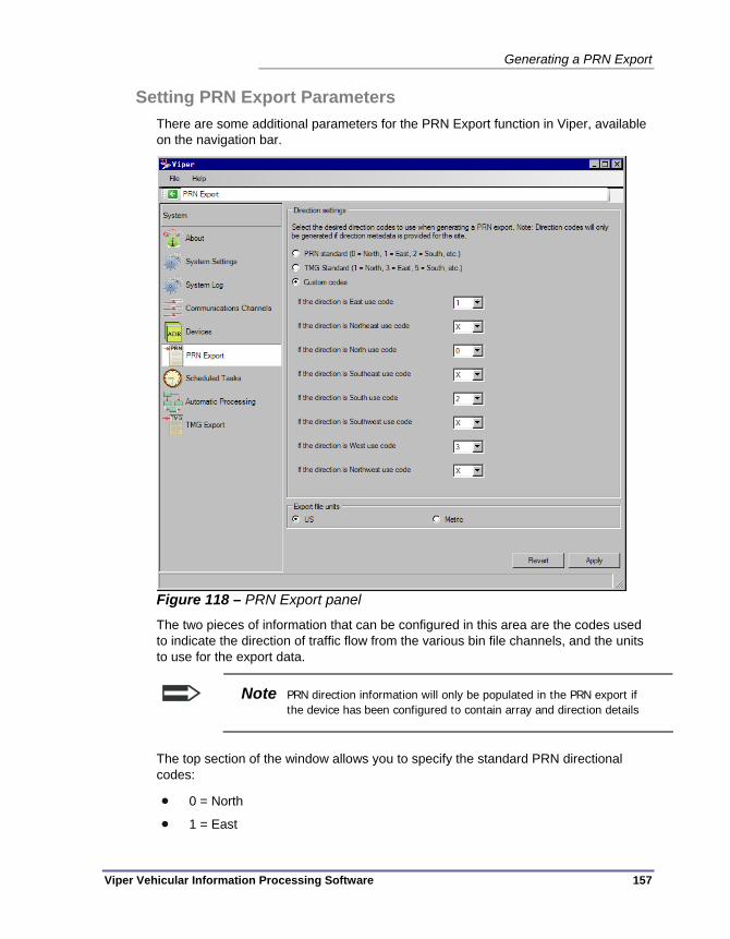
Generating a PRN Export
Viper Vehicular Information Processing Software 157
Setting PRN Export Parameters There are some additional parameters for the PRN Export function in Viper, available on the navigation bar.
Figure 118 – PRN Export panel
The two pieces of information that can be configured in this area are the codes used to indicate the direction of traffic flow from the various bin file channels, and the units to use for the export data.
Note PRN direction information will only be populated in the PRN export if the device has been configured to contain array and direction details
The top section of the window allows you to specify the standard PRN directional codes:
0 = North
1 = East

Chapter 8 — Exporting Data
158 Viper Vehicular Information Processing Software
2 = South
3 = West
X = Northeast, Southeast, Southwest, & Northwest
The TMG directional codes can also be selected:
1 = North
2 = Northeast
3 = East
4 = Southeast
5 = South
6 = Southwest
7 = West
8 = Northwest
If you select the Custom option, any direction can have a value between 0 and 9, or an X, indicating an ‘undefined’ direction. In the custom option, multiple directions can have the same coding, if you define it that way (i.e. Viper does not check to verify that a unique code is applied to each direction.)
Units can be set for the PRN Export to follow either the United States standard (mph/tons/feet) or the Metric standard (kph/KIPS/meters).
Again, as with the rest of the interface, use the Apply button to save any changes made to the PRN Export settings, or choose the Revert button to discard any changes and return to the values that were stored on this screen when you first opened it.

Generating a PRN Export
Viper Vehicular Information Processing Software 159
Activating the PRN Export Plan The final step in telling Viper to generate PRN exports is to go back into the Automatic Processing panel and tell Viper to use the plan with the Write PRN action as your current, running configuration in the auto-processing service:
1. Open the Automatic Processing panel in the Viper front-end interface.
2. If you just edited the auto-processing plan earlier in this session of the front-end interface, the plan that includes the Write PRN action should still be visible in the plan area. If so, skip to step 4.
3. Go to the File menu and select Load from file. Navigate to the directory and the .psm filename where you stored the PRN Export plan you created in the “Setting PRN File Names” section.
4. With the correct PRN export auto-processing plan visible, go to the File menu and choose Make currently displayed configuration active.
At this point, any binned data files that arrive in your Watch folder will automatically generate a PRN export file in the Output folder of your standard Viper data directory. (Or wherever you decided to send the export files.)

Chapter 8 — Exporting Data
160 Viper Vehicular Information Processing Software
GENERATING AN XML EXPORT The steps to generate an XML export are similar to a PRN export, but with a few less steps, since the XML export has fewer configurable parameters. As with PRN export, XML export only works for Binned data files.
The XML Export process converts the incoming binned data into standard XML files in a location of your choosing, with the option of selecting a custom naming convention for the output files.
These are the steps required to create XML exports:
1. Add the Write XML action to the Automatic Processing configuration (See “Adding the Write XML Action”, on page 160)
2. Define the naming convention to be used for the XML files and activate the auto-processing plan (See “Setting XML File Names”, on page 164)
Adding the Write XML Action To begin the process of generating an XML export, we first need to add an action to your auto-processing plan. Follow these steps to add the action:
1. Open the Auto-processing panel by selecting Automatic Processing in the navigation panel of Viper’s front end interface.
2. The rest of the processing plan should be in place, namely setting the Watch folder for incoming Bin files, and any file Move, Sorting, or renaming operations. The panel will open showing the plan that is currently running in the Auto-processing service. If you wish to edit the current plan, go to step 3 now, however if you wish to edit a plan that is stored in a file, go to the File menu and select Load from file. Open the .psm file that contains the auto-processing plan you wish to modify.
3. To add a Write XML action, you will need to have a Watch folder that will receive Binned data files, and you will need a workflow in place that will Read the binned data file into Viper. Figure 119 shows a workflow with a Read Binned data file operation (with its associated error handling action connected at the right connect point.) You can see that the Read action requires a next step, as indicated by the red connection dot at its bottom. This is where we will connect the Write XML action.
Note The Write XML action is typically added right below a Read Bin action, however it can also be placed beneath a Write PRN action, thus allowing both export actions to follow from a single Read Bin action.
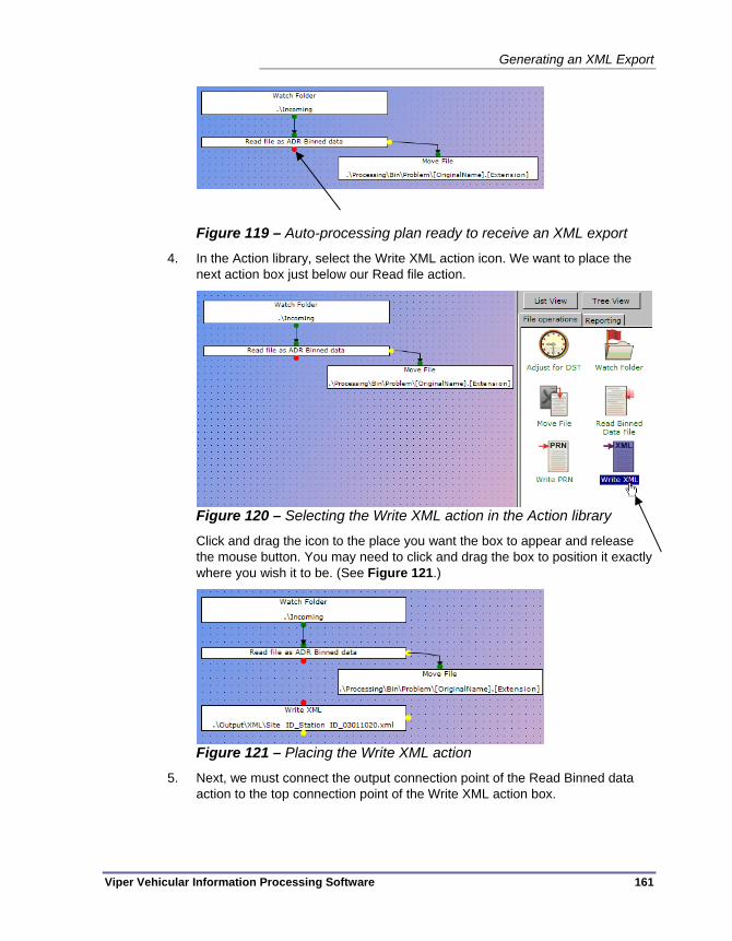
Generating an XML Export
Viper Vehicular Information Processing Software 161
Figure 119 – Auto-processing plan ready to receive an XML export
4. In the Action library, select the Write XML action icon. We want to place the next action box just below our Read file action.
Figure 120 – Selecting the Write XML action in the Action library
Click and drag the icon to the place you want the box to appear and release the mouse button. You may need to click and drag the box to position it exactly where you wish it to be. (See Figure 121.)
Figure 121 – Placing the Write XML action
5. Next, we must connect the output connection point of the Read Binned data action to the top connection point of the Write XML action box.

Chapter 8 — Exporting Data
162 Viper Vehicular Information Processing Software
Figure 122 – Connecting to the Write XML action
6. We need to add an error handling action to the right side of the Write XML box, in case the attempt to create the export results in an error (corrupted data, incorrect type of data file, etc.) One way to do this is just to Move the source file to a ‘problem files’ directory.
Figure 123 – Adding an error handling action to Write XML
7. Finally, adding a Move action to handle files after the XML export has been generated – This will prevent the auto-processing service from attempting to process the same bin files into duplicate XML files should the service be restarted.
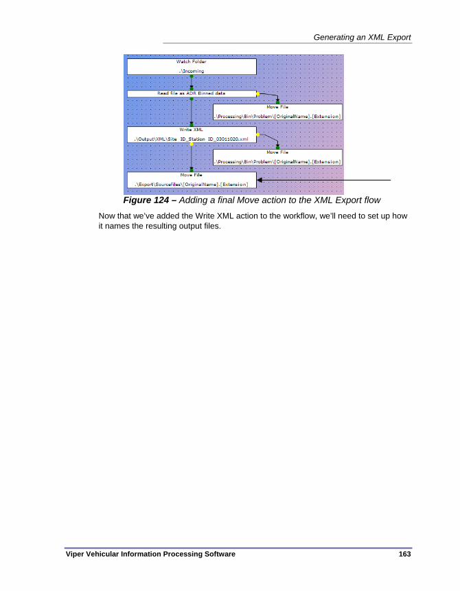
Generating an XML Export
Viper Vehicular Information Processing Software 163
Figure 124 – Adding a final Move action to the XML Export flow
Now that we’ve added the Write XML action to the workflow, we’ll need to set up how it names the resulting output files.

Chapter 8 — Exporting Data
164 Viper Vehicular Information Processing Software
Setting XML File Names and Activating the Plan To configure a standard design for your XML file names:
1. In the Viper front end interface, open the Automatic Processing panel and locate the Write XML action box. Double-click on the action box to configure the file naming parameters for the export function.
2. First, select the root path where the XML file name should start. For many users, the default setting of .\Output\XML will not need to be changed.
Figure 125 – Settings for the Export to XML operation
All of the fields on the above dialog box are detailed on page 115.
3. Select one or more of the name components from the left hand list and move them to the right hand list by clicking the button labeled >. If you make a mistake, the name component can be moved back to the left hand list by selecting it again and clicking the < button. You can also move all the items from one side to the other using the buttons marked >> and <<.The sample file name toward the bottom of the form shows approximately what the final file name will look like.
4. If desired, the order of the name elements can be modified by dragging them to a different position in the right-hand list.

Generating an XML Export
Viper Vehicular Information Processing Software 165
5. Make sure the appropriate radio button is selected to indicate if you want to generate a new name or overwrite the existing one in cases where there is a conflict. We recommend that you leave it on the default setting of generate a new name unless you are certain that the name generated will be unique. Remember that the same initial file name will always be generated if you are collecting multiple studies.
6. Click OK to save your new settings and then close the Configure File Naming dialog box.
7. Back in the Automatic Processing panel, go to the File menu and choose Save to File as.
8. Select a directory location and a file name to store the auto-processing configuration.
9. If you wish to have Viper begin to generate XML output for any new, incoming data files at this time, go to the File menu and choose Make currently displayed configuration active.
At this point, any binned data files that arrive in your Watch folder will automatically generate an XML export file in the Output folder of your standard Viper data directory. (Or wherever you decided to send the export files.)
Note Unlike the PRN format, XML files do support having multiple studies in a single file, if you have configured multiple studies at a site. So all of the data from the site will be stored to a single XML file upon export.

Chapter 8 — Exporting Data
166 Viper Vehicular Information Processing Software
GENERATING A TMG EXPORT The TMG exports that are generated by Viper are automatically updated as new data arrives. The TMG Export process converts incoming binned data into TMG-compliant data files in a location of your choosing. The configuration options for TMG exporting allow you to split the exports into time-period based subfolders (Weekly, Monthly, Quarterly, or Annually.)
The process of creating a TMG export has these steps:
1. Add the Write TMG action to the Automatic Processing configuration (See “Adding the Write TMG Action”, on page 166)
2. Setting Device parameters so the TMG export will generate valid export files (See “Configuring Devices for TMG S-Card Export”, on page 170)
3. Set the root export folder and the export period in the TMG Export panel (See “Setting TMG Export Parameters”, on page 171)
4. Activate the Auto-processing plan (See “Activating the TMG Export Plan”, on page 173)
Adding the Write TMG Action To begin the process of generating a TMG export, we first need to add an action to your auto-processing plan. Follow these steps to add the action:
1. Open the Auto-processing panel by selecting Automatic Processing in the navigation panel of Viper’s front end interface.
2. The rest of the processing plan should be in place, namely setting the Watch folder for incoming Bin files, and any file Move, Sorting, or renaming operations. The panel will open showing the plan that is currently running in the Auto-processing service. If you wish to edit the current plan, go to step 3 now, however if you wish to edit a plan that is stored in a file, go to the File menu and select Load from file. Open the .psm file that contains the auto-processing plan you wish to modify.
3. To add a Write TMG action, you will need to have a Watch folder that will receive Binned data files. Note that, unlike the Write PRN and Write XML actions, Write TMG does not require a Read action before it can be called. In fact, Write TMG cannot be attached to a Read action. It simply requires a watch folder. Figure 126 shows a workflow with a Watch folder in place. This is where we will connect the Write TMG action.
Note Unlike the Write XML and Write PRN actions, Write TMG cannot be placed at the outfeed side of another Write action. It requires a Watch folder input. However, Write TMG can be at the top of a workflow that then feeds into Write XML and Write PRN actions below it. In this way, a single workflow can be set up to generate all three types of export.

Generating a TMG Export
Viper Vehicular Information Processing Software 167
Figure 126 – Auto-processing plan ready to receive a TMG export
4. In the Action library, select the Write TMG action icon. We want to place the next action box just below our Watch Folder action.
Figure 127 – Selecting the Write TMG action in the Action library
Click and drag the icon to the place you want the box to appear and release the mouse button. You may need to click and drag the box to position it exactly where you wish it to be. (See Figure 128.)
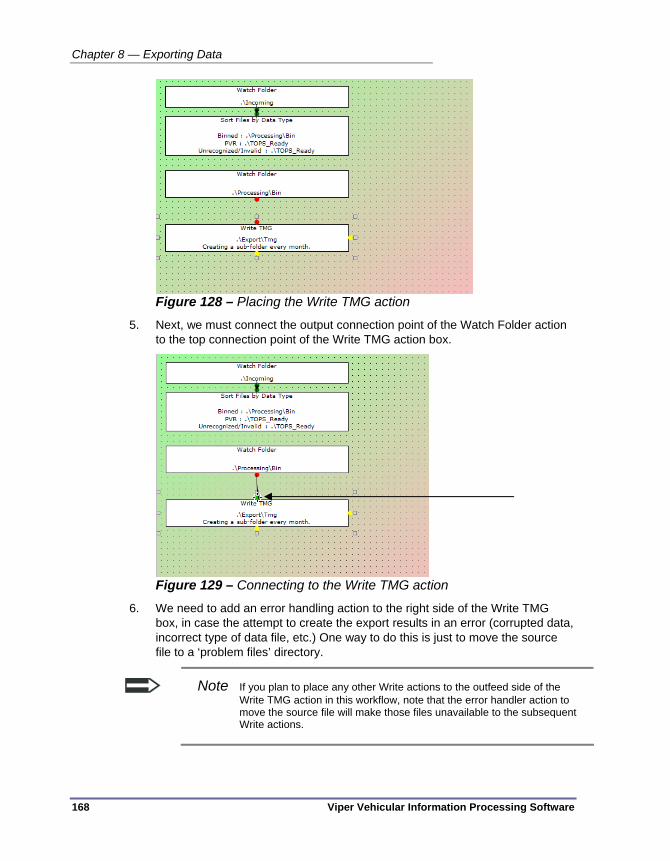
Chapter 8 — Exporting Data
168 Viper Vehicular Information Processing Software
Figure 128 – Placing the Write TMG action
5. Next, we must connect the output connection point of the Watch Folder action to the top connection point of the Write TMG action box.
Figure 129 – Connecting to the Write TMG action
6. We need to add an error handling action to the right side of the Write TMG box, in case the attempt to create the export results in an error (corrupted data, incorrect type of data file, etc.) One way to do this is just to move the source file to a ‘problem files’ directory.
Note If you plan to place any other Write actions to the outfeed side of the Write TMG action in this workflow, note that the error handler action to move the source file will make those files unavailable to the subsequent Write actions.

Generating a TMG Export
Viper Vehicular Information Processing Software 169
Figure 130 – Adding an error handling action to Write TMG
7. Finally, adding a Move action to handle files after the TMG export has been generated – This will prevent the auto-processing service from attempting to process the same bin files into the export file.
Figure 131 – Adding a final Move action to the TMG Export flow
8. Go to the File menu and choose Save to File as.
9. Select a directory location and a file name to store the auto-processing configuration.
Now that we’ve added TMG Export to an auto-processing configuration and saved the file, we need to verify that all of the devices that will feed data into the export have been properly configured to provide all of the required TMG parameter values.

Chapter 8 — Exporting Data
170 Viper Vehicular Information Processing Software
Configuring Devices for TMG S-Card Export Some users have reported problems when setting up a TMG S-Card file export. They find that the TMG S-Card file which is produced does not contain any information about the station. The file is empty and is reported as “0” bytes by Windows Explorer even though the volume card is produced and appears to have valid data when opened.
The following lists show the minimum pieces of Device information that must be properly configured before a valid TMG S record can be created for a site.
On the Devices > Identification tab:
County
State
On the Devices > Site tab:
Site ID (must match what will appear in files from that device)
Station Number (must match what will appear in files from that device)
Number of arrays (should match what will appear in files from that device)
At least one array must have a check-mark in the TMG Volume, TMG Class or TMG Weight columns.
On the Devices > TMG tab:
TMG Station identification
Functional class
After we make sure the devices that provide the source data for the TMG export are all properly configured, next we need to set up where the export stores the resulting output files and how often it splits the outputs into new folders.

Generating a TMG Export
Viper Vehicular Information Processing Software 171
Setting TMG Export Parameters There are some additional parameters for the TMG Export function in Viper, available on the navigation bar.
Figure 132 – TMG Export panel
The three pieces of information that can be configured in this area are the root folder for the export files, how the export is split up over time, and a station file prefex code to use on the export’s station file.
When generating TMG export data, place it in the folder — This is the root folder or network drive location for your TMG export data. Note that no data will be placed directly in this folder, but rather in the subdirectories it contains, named based on the time period each export will cover. (See the next item below.) The default location for this is a directory called Export\Tmg, placed in the default Viper data directory (as defined in Viper’s System Settings panel.)
creating a sub-folder for each — Within the root TMG export data folder, Viper will create a folder based on the time period to be covered by each export. TMG exports are typically done either monthly or quarterly, but some may have a need to split them out weekly, or to generate annual versions of the export data.

Chapter 8 — Exporting Data
172 Viper Vehicular Information Processing Software
Name the station file using the prefix for — A two letter prefix added to the beginning of the TMG export station file, indicating the state where the data collection hardware is located.
Again, as with the rest of the interface, use the Apply button to save any changes made to the TMG Export settings, or choose the Revert button to discard any changes and return to the values that were stored on this screen when you first opened it.

Generating a TMG Export
Viper Vehicular Information Processing Software 173
Activating the TMG Export Plan The final step in setting up Viper to generate TMG exports is to go back into the Automatic Processing panel and tell Viper to use the plan with the Write TMG action as your current, running configuration in the auto-processing service:
1. Open the Automatic Processing panel in the Viper front-end interface.
2. If you just edited the auto-processing plan earlier in this session of the front-end interface, the plan that includes the Write TMG action should still be visible in the plan area. If so, skip to step 4.
3. Go to the File menu and select Load from file. Navigate to the directory and the .psm filename where you stored the TMG Export plan you created in the “Adding the Write TMG Action” section.
4. With the correct TMG export auto-processing plan visible, go to the File menu and choose Make currently displayed configuration active.
At this point, any binned data files that arrive in your Watch folder will automatically be processed and the data added to your export TMG file(s) in the Export\Tmg folder of your standard Viper data directory. (Or wherever you decided to send the export files.)

Chapter 8 — Exporting Data
174 Viper Vehicular Information Processing Software
GENERATING A VIPER REPORT Generating a report from Viper is handled in much the same way that a data export is, namely, a special type of action is added to the Viper Auto-processing service that tells it to use its available data to generate the report. A set of pre-configured reports are included with the Viper installation:
Class (Binned data)
Volume (Binned data)
Speed (Binned data)
Class by Channel (Binned data)
Auto-polling Summary (Viper activity)
It is important to remember that the reporting capabilities of Viper are not similar to those of the TOPS application. TOPS was able to store data and aggregate reports for many stations and over variable time periods. Viper is designed to operate without requiring a long-term data store, as that function is typically accomplished using a customer’s established in-house systems. This means that all data processing, including report generation is done on a data file by data file basis. In other words, each data file that is received will generate a single output report, based on the available report template. The report templates are designed and implemented using a report generation tool called Crystal Reports. If you have a copy of Crystal Reports, you can create your own templates for Viper. Crystal Reports is a third party application available from SAP Global corporation (www.crystalreports.com). Other than for contracted custom reports, Peek Traffic does not provide support for the Crystal Reports product.
Note Custom reports can be requested for Viper from Peek Traffic on a contract basis. Please contact the AVCC Product Manager at Peek Traffic, at (941) 845-1266. Reports can only be created to use a single source (bin) file, which typically contains 24 hours of data. This version of Viper does not support complex reports (such as multi-day or multi-dimensional reports).
The process of generating a data report in Viper has these steps:
1. Add the Generate Report action to the Automatic Processing configuration (See “Adding the Generate Report Action”, on page 175.)
2. Defining the report options (See “Setting Report Options”, on page 179.)
3. Activate the report-generating Auto-processing plan (See “Activating the Report Plan”, on page 181.)

Generating a Viper Report
Viper Vehicular Information Processing Software 175
Adding the Generate Report Action To begin the process of generating a Viper report, we first need to add an action to your auto-processing plan. Follow these steps to add the action:
1. Open the Auto-processing panel by selecting Automatic Processing in the navigation panel of Viper’s front end interface.
2. The rest of the processing plan should be in place, namely setting the Watch folder for incoming Bin files, and any file Move, Sorting, or renaming operations. The panel will open showing the plan that is currently running in the Auto-processing service. If you wish to edit the current plan, go to step 3 now, however if you wish to edit a plan that is stored in a file, go to the File menu and select Load from file. Open the .psm file that contains the auto-processing plan you wish to modify.
3. To add a Generate Report action, you will need to have a Watch folder that will receive Binned data files, and you will need a workflow in place that will read the binned data file into Viper. Figure 133 shows a workflow with a Read Binned data file operation (with its associated error handling action connected at the right connect point.) You can see that the Read action requires a next step, as indicated by the red connection dot at its bottom. This is where we will connect the Generate Report action.
Note The Generate Report action is typically added right below a Read Bin action, however it can also be placed beneath any of the Write actions as well, thus allowing both export and report generation actions to follow from a single Read.
Figure 133 – Auto-processing plan ready to receive a report action
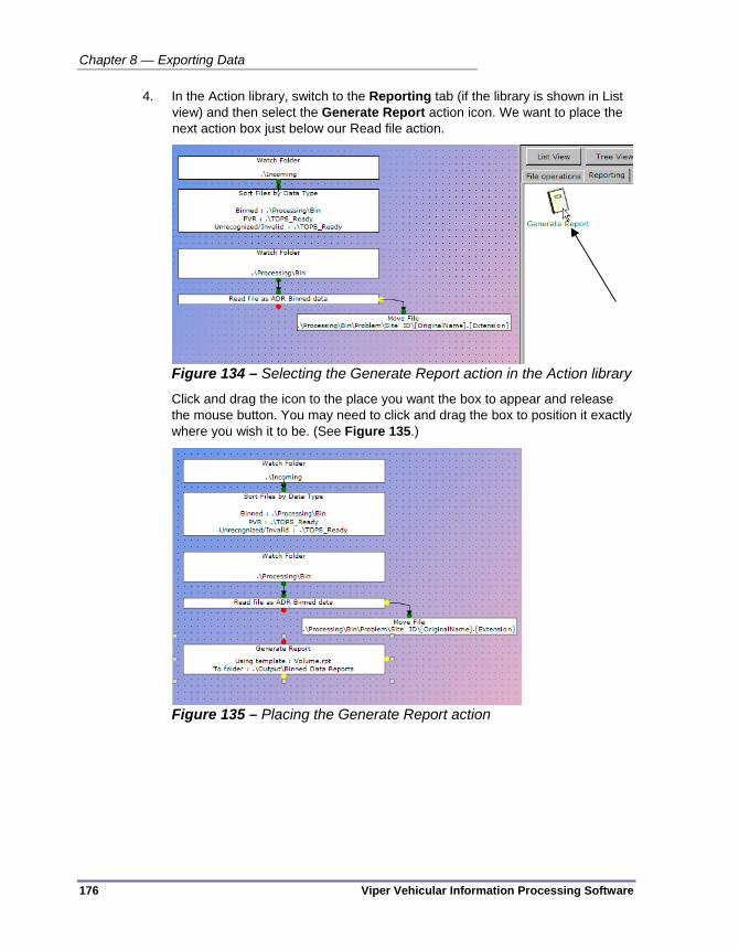
Chapter 8 — Exporting Data
176 Viper Vehicular Information Processing Software
4. In the Action library, switch to the Reporting tab (if the library is shown in List view) and then select the Generate Report action icon. We want to place the next action box just below our Read file action.
Figure 134 – Selecting the Generate Report action in the Action library
Click and drag the icon to the place you want the box to appear and release the mouse button. You may need to click and drag the box to position it exactly where you wish it to be. (See Figure 135.)
Figure 135 – Placing the Generate Report action

Generating a Viper Report
Viper Vehicular Information Processing Software 177
5. Next, we must connect the output connection point of the Read Binned data action to the top connection point of the Generate Report action box.
Figure 136 – Connecting to the Generate Report action
6. We need to add an error handling action to the right side of the Generate Report box, in case the attempt to create the report results in an error. One way to do this is just to move the source file to a ‘problem files’ directory.
Figure 137 – Adding an error handling action to Generate Report

Chapter 8 — Exporting Data
178 Viper Vehicular Information Processing Software
7. Finally, adding a Move action to handle files after the report has been generated – This will prevent the auto-processing service from attempting to process the same bin files into duplicate reports if the service is restarted.
Figure 138 – Adding a final Move action to the report generation flow
Now that we’ve added the Generate Report action to the workflow, we’ll need to set up which report to generate and how Viper names the resulting output files.
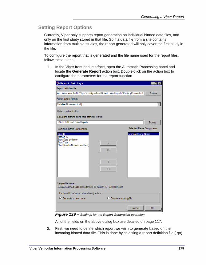
Generating a Viper Report
Viper Vehicular Information Processing Software 179
Setting Report Options Currently, Viper only supports report generation on individual binned data files, and only on the first study stored in that file. So if a data file from a site contains information from multiple studies, the report generated will only cover the first study in the file.
To configure the report that is generated and the file name used for the report files, follow these steps:
1. In the Viper front end interface, open the Automatic Processing panel and locate the Generate Report action box. Double-click on the action box to configure the parameters for the report function.
Figure 139 – Settings for the Report Generation operation
All of the fields on the above dialog box are detailed on page 117.
2. First, we need to define which report we wish to generate based on the incoming binned data file. This is done by selecting a report definition file (.rpt)

Chapter 8 — Exporting Data
180 Viper Vehicular Information Processing Software
from the Viper directories. Use the Browse button to locate the file you wish to use. (The default location for these are in two directories, which relative to the Viper root path for data, are .\Configuration\ReportDefinitions and .\Configuration\Binned Data Reports.) Select a template file and choose Open.
3. Next, we’ll need to select the type of output file you would like. From the drop-down box, choose either PDF, Excel, or a text file.
4. Now we need to set the root path where the report filename and location should begin. For many users, the default setting of .\Output\Binned Data Reports will not need to be changed.
5. Select one or more of the name components from the left hand list and move them to the right hand list by clicking the button labeled >. If you make a mistake, the name component can be moved back to the left hand list by selecting it again and clicking the < button. You can also move all the items from one side to the other using the buttons marked >> and <<.The sample file name toward the bottom of the form shows approximately what the final file name will look like.
6. If desired, the order of the name elements can be modified by dragging them to a different position in the right-hand list.
7. Make sure the appropriate radio button is selected to indicate if you want to generate a new name or overwrite the existing one in cases where there is a conflict. We recommend that you leave it on the default setting of generate a new name unless you are certain that the name generated will be unique. Remember that the same initial file name will always be generated if you are collecting multiple studies.
8. Click OK to save your new settings and then close the Report Settings dialog box.
9. Back in the Automatic Processing panel, go to the File menu and choose Save to File as.
10. Select a directory location and a file name to store the auto-processing configuration.

Generating a Viper Report
Viper Vehicular Information Processing Software 181
Activating the Report Plan The final step in telling Viper to generate reports is to go back into the Automatic Processing panel and tell Viper to use the plan with the Generate Report action as your current, running configuration in the auto-processing service:
1. Open the Automatic Processing panel in the Viper front-end interface.
2. If you just edited the auto-processing plan earlier in this session of the front-end interface, the plan that includes the Generate Report action should still be visible in the plan area. If so, skip to step 4.
3. Go to the File menu and select Load from file. Navigate to the directory and the .psm filename where you stored the Report Generation plan you created in the previous section.
4. With the correct plan visible, go to the File menu and choose Make currently displayed configuration active.
At this point, any binned data files that arrive in your Watch folder will automatically generate a report file in the Output\Binned Report Files folder of your standard Viper data directory. (Or wherever you decided to send the report files.)

Chapter 8 — Exporting Data
182 Viper Vehicular Information Processing Software
Example Reports
Class Report - Example
0K
2K
4K
6K
8K
10K
12K
Class 1 Class 2 Class 3 Class 4 Class 5 Class 6 Class 7 Class 8 Class 9 Class 10 Class 11 Class 12 Class 13 Class 14 Other
Class 1Class 2Class 3Class 4Class 5Class 6Class 7Class 8Class 9Class 10Class 11Class 12Class 13Class 14Other
Class
Vehi
cle
Cou
nt
Vehicles by Class
Class 1
Class 2
Class 3
Class 4
Class 5
Class 6
Class 7
Class 8
Class 9
Class 10
Class 11
Class 12
Class 13
Class 14 Other Total
00:00:00 0 300 44 3 2 16 0 8 36 3 0 1 0 0 0 413
01:00:00 3 94 15 2 2 1 0 0 28 0 3 0 0 0 0 148
02:00:00 1 96 9 0 0 1 0 3 26 0 3 0 0 0 0 139
03:00:00 2 75 9 0 1 1 0 1 20 1 3 0 0 0 0 113
04:00:00 1 51 3 5 1 2 0 2 27 0 5 0 0 1 0 98
05:00:00 0 49 9 4 3 0 0 2 20 0 4 0 0 0 0 91
06:00:00 1 53 11 1 2 0 0 0 21 0 6 0 0 0 0 95
07:00:00 3 78 17 0 2 0 0 4 21 0 4 0 0 0 0 129
08:00:00 6 101 28 2 4 3 0 7 24 0 4 0 0 0 0 179
09:00:00 9 209 53 1 5 12 0 5 37 0 4 0 0 1 0 336
10:00:00 9 367 57 3 9 7 0 6 56 1 6 1 0 0 0 522
11:00:00 9 590 96 3 8 14 0 12 63 1 4 0 0 0 0 800
12:00:00 4 718 117 3 6 11 0 9 69 2 4 1 0 0 0 944
13:00:00 1 814 142 11 10 11 0 10 79 0 11 0 0 0 0 1089
14:00:00 1 872 120 7 15 16 2 17 82 0 5 1 0 0 0 1138
15:00:00 1 922 121 4 20 14 1 10 81 0 4 0 0 0 0 1178
16:00:00 2 949 135 5 15 25 0 9 66 2 9 0 0 0 0 1217
17:00:00 1 908 132 6 9 14 0 16 68 0 0 1 0 5 0 1160
18:00:00 0 820 128 7 22 16 1 7 75 1 6 0 0 0 0 1083
19:00:00 0 648 119 3 11 11 0 10 56 0 1 0 0 0 0 859
20:00:00 2 544 76 2 8 6 0 7 63 0 3 1 0 0 0 712
21:00:00 1 477 56 1 6 9 0 10 62 0 1 1 1 0 0 625
22:00:00 0 368 57 2 4 2 0 3 34 0 5 0 0 0 0 475
23:00:00 1 383 29 6 3 15 1 12 39 1 1 1 1 3 0 496
Total 58 10486 1583 81 168 207 5 170 1153 12 96 8 2 10 0 14039

Generating a Viper Report
Viper Vehicular Information Processing Software 183
Speed Report - Example
19 mph 22 mph 25 mph 28 mph 31 mph 34 mph 37 mph 143 mph 147 mph All Speeds
00:00:00 2 0 4 12 20 25 11 7 0 81
01:00:00 0 2 0 4 7 4 4 2 0 23
02:00:00 0 1 1 1 1 5 3 2 0 14
03:00:00 1 0 2 1 5 3 1 1 0 14
04:00:00 2 0 0 0 1 1 1 1 0 6
05:00:00 0 0 0 1 4 6 6 5 0 22
06:00:00 0 0 2 6 14 17 11 10 0 60
07:00:00 0 0 5 28 46 49 26 8 0 162
08:00:00 1 4 13 42 98 86 42 17 0 303
09:00:00 3 7 27 47 84 75 44 22 0 309
10:00:00 0 12 21 40 80 65 20 12 0 250
11:00:00 0 13 30 82 103 67 27 9 0 331
12:00:00 4 5 29 92 127 89 40 18 0 404
13:00:00 5 7 34 88 128 84 33 17 0 396
14:00:00 7 18 37 79 114 104 55 14 0 428
15:00:00 3 10 27 73 128 80 32 11 0 364
16:00:00 3 14 24 71 129 116 54 14 0 425
17:00:00 11 20 52 149 186 159 74 26 0 677
18:00:00 8 13 54 153 210 142 61 17 0 658
19:00:00 4 7 53 145 223 148 48 25 0 653
20:00:00 8 18 75 145 141 84 31 7 0 509
21:00:00 4 28 54 113 115 46 22 4 0 386
22:00:00 3 9 31 60 73 59 28 14 0 277
23:00:00 1 2 6 32 45 43 20 11 0 160
Total 70 190 581 1464 2082 1557 694 274 0 6912
1 12/2/10
0
400
800
1200
1600
2000
2400
19 mph 22 mph 25 mph 28 mph 31 mph 34 mph 37 mph 143 mph 147 mph
19 mph22 mph25 mph28 mph31 mph34 mph37 mph143 mph147 mph
Speed
Tota
l Veh
icle
s
Vehicle Count by Speed

Chapter 8 — Exporting Data
184 Viper Vehicular Information Processing Software
Class by Channel Report - Example
Class 1 Class 2 Class 3 Class 4 Class 5 Class 6 Class 7 Class 8 Class 9 Class 10 Class 11 Class 12 Class 13 Class 14 Other Total
Channel 1 0 128 22 3 2 0 0 0 14 0 0 0 0 0 0 169 Channel 2 0 22 5 0 0 0 0 1 0 0 0 0 0 0 0 28 Channel 3 0 116 17 0 0 16 0 6 22 3 0 1 0 0 0 181
00:00:00
Channel 4 0 34 0 0 0 0 0 1 0 0 0 0 0 0 0 35 Total 0 300 44 3 2 16 0 8 36 3 0 1 0 0 0 413
Channel 1 0 39 5 0 1 0 0 0 10 0 1 0 0 0 0 56 Channel 2 0 4 1 0 0 0 0 0 0 0 0 0 0 0 0 5 Channel 3 1 35 9 2 1 1 0 0 18 0 2 0 0 0 0 69
01:00:00
Channel 4 2 16 0 0 0 0 0 0 0 0 0 0 0 0 0 18 Total 3 94 15 2 2 1 0 0 28 0 3 0 0 0 0 148
Channel 1 0 31 5 0 0 0 0 1 12 0 2 0 0 0 0 51 Channel 2 0 3 0 0 0 0 0 0 1 0 0 0 0 0 0 4 Channel 3 0 40 4 0 0 1 0 2 12 0 1 0 0 0 0 60
02:00:00
Channel 4 1 22 0 0 0 0 0 0 1 0 0 0 0 0 0 24 Total 1 96 9 0 0 1 0 3 26 0 3 0 0 0 0 139
Channel 1 0 30 5 0 0 0 0 0 11 0 2 0 0 0 0 48 Channel 2 0 4 0 0 0 0 0 0 0 0 0 0 0 0 0 4 Channel 3 0 31 4 0 1 1 0 1 9 1 1 0 0 0 0 49
03:00:00
Channel 4 2 10 0 0 0 0 0 0 0 0 0 0 0 0 0 12 Total 2 75 9 0 1 1 0 1 20 1 3 0 0 0 0 113
Channel 1 0 15 3 1 1 0 0 0 15 0 3 0 0 1 0 39 Channel 2 0 1 0 0 0 0 0 0 1 0 0 0 0 0 0 2 Channel 3 0 30 0 4 0 2 0 2 11 0 2 0 0 0 0 51
04:00:00
Channel 4 1 5 0 0 0 0 0 0 0 0 0 0 0 0 0 6 Total 1 51 3 5 1 2 0 2 27 0 5 0 0 1 0 98
Channel 1 0 21 5 2 1 0 0 2 10 0 3 0 0 0 0 44 Channel 2 0 3 0 0 0 0 0 0 0 0 0 0 0 0 0 3 Channel 3 0 22 3 2 2 0 0 0 10 0 1 0 0 0 0 40
05:00:00
Channel 4 0 3 1 0 0 0 0 0 0 0 0 0 0 0 0 4 Total 0 49 9 4 3 0 0 2 20 0 4 0 0 0 0 91 06:00:00 Channel 1 0 21 5 0 2 0 0 0 9 0 5 0 0 0 0 42
0K
2K
4K
6K
8K
10K
12K
Class 1 Class 2 Class 3 Class 4 Class 5 Class 6 Class 7 Class 8 Class 9 Class 10 Class 11 Class 12 Class 13 Class 14 Other
Class 1Class 2Class 3Class 4Class 5Class 6Class 7Class 8Class 9Class 10Class 11Class 12Class 13Class 14Other
Class
Vehi
cle
Cou
nt
Vehicles by Class
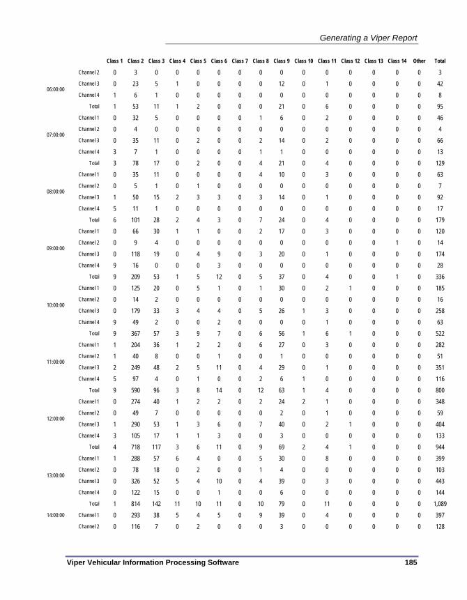
Generating a Viper Report
Viper Vehicular Information Processing Software 185
Class 1 Class 2 Class 3 Class 4 Class 5 Class 6 Class 7 Class 8 Class 9 Class 10 Class 11 Class 12 Class 13 Class 14 Other Total
Channel 2 0 3 0 0 0 0 0 0 0 0 0 0 0 0 0 3 Channel 3 0 23 5 1 0 0 0 0 12 0 1 0 0 0 0 42
06:00:00 Channel 4 1 6 1 0 0 0 0 0 0 0 0 0 0 0 0 8
Total 1 53 11 1 2 0 0 0 21 0 6 0 0 0 0 95 Channel 1 0 32 5 0 0 0 0 1 6 0 2 0 0 0 0 46 Channel 2 0 4 0 0 0 0 0 0 0 0 0 0 0 0 0 4 Channel 3 0 35 11 0 2 0 0 2 14 0 2 0 0 0 0 66
07:00:00
Channel 4 3 7 1 0 0 0 0 1 1 0 0 0 0 0 0 13 Total 3 78 17 0 2 0 0 4 21 0 4 0 0 0 0 129
Channel 1 0 35 11 0 0 0 0 4 10 0 3 0 0 0 0 63 Channel 2 0 5 1 0 1 0 0 0 0 0 0 0 0 0 0 7 Channel 3 1 50 15 2 3 3 0 3 14 0 1 0 0 0 0 92
08:00:00
Channel 4 5 11 1 0 0 0 0 0 0 0 0 0 0 0 0 17 Total 6 101 28 2 4 3 0 7 24 0 4 0 0 0 0 179
Channel 1 0 66 30 1 1 0 0 2 17 0 3 0 0 0 0 120 Channel 2 0 9 4 0 0 0 0 0 0 0 0 0 0 1 0 14 Channel 3 0 118 19 0 4 9 0 3 20 0 1 0 0 0 0 174
09:00:00
Channel 4 9 16 0 0 0 3 0 0 0 0 0 0 0 0 0 28 Total 9 209 53 1 5 12 0 5 37 0 4 0 0 1 0 336
Channel 1 0 125 20 0 5 1 0 1 30 0 2 1 0 0 0 185 Channel 2 0 14 2 0 0 0 0 0 0 0 0 0 0 0 0 16 Channel 3 0 179 33 3 4 4 0 5 26 1 3 0 0 0 0 258
10:00:00
Channel 4 9 49 2 0 0 2 0 0 0 0 1 0 0 0 0 63 Total 9 367 57 3 9 7 0 6 56 1 6 1 0 0 0 522
Channel 1 1 204 36 1 2 2 0 6 27 0 3 0 0 0 0 282 Channel 2 1 40 8 0 0 1 0 0 1 0 0 0 0 0 0 51 Channel 3 2 249 48 2 5 11 0 4 29 0 1 0 0 0 0 351
11:00:00
Channel 4 5 97 4 0 1 0 0 2 6 1 0 0 0 0 0 116 Total 9 590 96 3 8 14 0 12 63 1 4 0 0 0 0 800
Channel 1 0 274 40 1 2 2 0 2 24 2 1 0 0 0 0 348 Channel 2 0 49 7 0 0 0 0 0 2 0 1 0 0 0 0 59 Channel 3 1 290 53 1 3 6 0 7 40 0 2 1 0 0 0 404
12:00:00
Channel 4 3 105 17 1 1 3 0 0 3 0 0 0 0 0 0 133 Total 4 718 117 3 6 11 0 9 69 2 4 1 0 0 0 944
Channel 1 1 288 57 6 4 0 0 5 30 0 8 0 0 0 0 399 Channel 2 0 78 18 0 2 0 0 1 4 0 0 0 0 0 0 103 Channel 3 0 326 52 5 4 10 0 4 39 0 3 0 0 0 0 443
13:00:00
Channel 4 0 122 15 0 0 1 0 0 6 0 0 0 0 0 0 144 Total 1 814 142 11 10 11 0 10 79 0 11 0 0 0 0 1,089
Channel 1 0 293 38 5 4 5 0 9 39 0 4 0 0 0 0 397 14:00:00
Channel 2 0 116 7 0 2 0 0 0 3 0 0 0 0 0 0 128
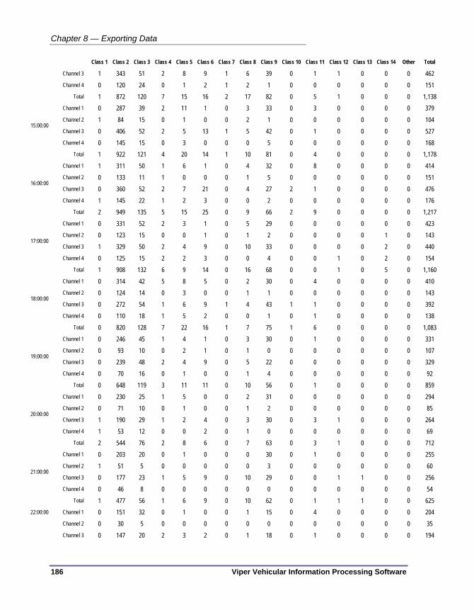
Chapter 8 — Exporting Data
186 Viper Vehicular Information Processing Software
Class 1 Class 2 Class 3 Class 4 Class 5 Class 6 Class 7 Class 8 Class 9 Class 10 Class 11 Class 12 Class 13 Class 14 Other Total
Channel 3 1 343 51 2 8 9 1 6 39 0 1 1 0 0 0 462 Channel 4 0 120 24 0 1 2 1 2 1 0 0 0 0 0 0 151
Total 1 872 120 7 15 16 2 17 82 0 5 1 0 0 0 1,138 Channel 1 0 287 39 2 11 1 0 3 33 0 3 0 0 0 0 379 Channel 2 1 84 15 0 1 0 0 2 1 0 0 0 0 0 0 104 Channel 3 0 406 52 2 5 13 1 5 42 0 1 0 0 0 0 527
15:00:00
Channel 4 0 145 15 0 3 0 0 0 5 0 0 0 0 0 0 168 Total 1 922 121 4 20 14 1 10 81 0 4 0 0 0 0 1,178
Channel 1 1 311 50 1 6 1 0 4 32 0 8 0 0 0 0 414 Channel 2 0 133 11 1 0 0 0 1 5 0 0 0 0 0 0 151 Channel 3 0 360 52 2 7 21 0 4 27 2 1 0 0 0 0 476
16:00:00
Channel 4 1 145 22 1 2 3 0 0 2 0 0 0 0 0 0 176 Total 2 949 135 5 15 25 0 9 66 2 9 0 0 0 0 1,217
Channel 1 0 331 52 2 3 1 0 5 29 0 0 0 0 0 0 423 Channel 2 0 123 15 0 0 1 0 1 2 0 0 0 0 1 0 143 Channel 3 1 329 50 2 4 9 0 10 33 0 0 0 0 2 0 440
17:00:00
Channel 4 0 125 15 2 2 3 0 0 4 0 0 1 0 2 0 154 Total 1 908 132 6 9 14 0 16 68 0 0 1 0 5 0 1,160
Channel 1 0 314 42 5 8 5 0 2 30 0 4 0 0 0 0 410 Channel 2 0 124 14 0 3 0 0 1 1 0 0 0 0 0 0 143 Channel 3 0 272 54 1 6 9 1 4 43 1 1 0 0 0 0 392
18:00:00
Channel 4 0 110 18 1 5 2 0 0 1 0 1 0 0 0 0 138 Total 0 820 128 7 22 16 1 7 75 1 6 0 0 0 0 1,083
Channel 1 0 246 45 1 4 1 0 3 30 0 1 0 0 0 0 331 Channel 2 0 93 10 0 2 1 0 1 0 0 0 0 0 0 0 107 Channel 3 0 239 48 2 4 9 0 5 22 0 0 0 0 0 0 329
19:00:00
Channel 4 0 70 16 0 1 0 0 1 4 0 0 0 0 0 0 92 Total 0 648 119 3 11 11 0 10 56 0 1 0 0 0 0 859
Channel 1 0 230 25 1 5 0 0 2 31 0 0 0 0 0 0 294 Channel 2 0 71 10 0 1 0 0 1 2 0 0 0 0 0 0 85 Channel 3 1 190 29 1 2 4 0 3 30 0 3 1 0 0 0 264
20:00:00
Channel 4 1 53 12 0 0 2 0 1 0 0 0 0 0 0 0 69 Total 2 544 76 2 8 6 0 7 63 0 3 1 0 0 0 712
Channel 1 0 203 20 0 1 0 0 0 30 0 1 0 0 0 0 255 Channel 2 1 51 5 0 0 0 0 0 3 0 0 0 0 0 0 60 Channel 3 0 177 23 1 5 9 0 10 29 0 0 1 1 0 0 256
21:00:00
Channel 4 0 46 8 0 0 0 0 0 0 0 0 0 0 0 0 54 Total 1 477 56 1 6 9 0 10 62 0 1 1 1 0 0 625
Channel 1 0 151 32 0 1 0 0 1 15 0 4 0 0 0 0 204 Channel 2 0 30 5 0 0 0 0 0 0 0 0 0 0 0 0 35
22:00:00
Channel 3 0 147 20 2 3 2 0 1 18 0 1 0 0 0 0 194

Generating a Viper Report
Viper Vehicular Information Processing Software 187
Class 1 Class 2 Class 3 Class 4 Class 5 Class 6 Class 7 Class 8 Class 9 Class 10 Class 11 Class 12 Class 13 Class 14 Other Total
Channel 4 0 40 0 0 0 0 0 1 1 0 0 0 0 0 0 42 Total 0 368 57 2 4 2 0 3 34 0 5 0 0 0 0 475
Channel 1 0 142 12 1 1 1 0 2 18 0 1 0 0 0 0 178 Channel 2 0 29 3 0 0 0 0 0 0 0 0 0 0 0 0 32 Channel 3 1 162 11 5 1 13 1 10 21 1 0 1 1 3 0 231
23:00:00
Channel 4 0 50 3 0 1 1 0 0 0 0 0 0 0 0 0 55 Total 1 383 29 6 3 15 1 12 39 1 1 1 1 3 0 496 Total 58 10,486 1,583 81 168 207 5 170 1,153 12 96 8 2 10 0 14,039

Chapter 8 — Exporting Data
188 Viper Vehicular Information Processing Software

Viper Vehicular Information Processing Software 189
Chapter 9 — System Maintenance
This chapter introduces the System Maintenance tools and procedures that can be used to keep Viper operating correctly. The following topics are discussed in detail in this chapter:
• Global settings stored on the System Settings pane, on page 190.
• Configuration steps and possible uses of the Viper logging tools, on page 195.
• A set of Troubleshooting steps that can help diagnose problems, on page 198.
• Instructions for uninstalling Viper, on page 202.

Chapter 9 — System Maintenance
190 Viper Vehicular Information Processing Software
SYSTEM SETTINGS The System Settings pane of the Viper interface is used to set global settings for how Viper will function. To open the System Settings pane, open the Viper interface and click on System Settings in the navigation bar.
Figure 140 – Viper System Settings pane
File Storage Paths Since a primary function of Viper is to move data in and out to various files, the file storage paths of the application are an important function. The following values provide a default location for files, but these values can be overridden by individual file functions within the Automatic Processing module.
Root path for data — This is the basic path that Viper will use as the root directory for all file imports and exports. If you wish to change the root path directly, you can click (or click and drag) in this box and type the new value. The default value for the root path under Windows XP is C:\Documents and Settings\All Users\Application Data\Peek Traffic\Viper\. For Windows 7, the root path is C:\ProgramData\Peek Traffic\. Unlike the other paths on this page, the Root path cannot be a relative path; it must be a direct path. (i.e. the text of the path cannot start with a period.) If you have a small C partition configured, which is often the case, you may wish to place data somewhere else on your system or local

System Settings
Viper Vehicular Information Processing Software 191
network, since Viper can eat up a great deal of hard drive space when processing data for multiple stations or when generating PVR output reports.
If you do type in a new Root path value and the directory name does not yet exist in your local or network environment, Viper will ask if you wish to create the chosen directory:
Figure 141 – Query about creating a new root directory
If you do opt to change this value, you will be presented with a warning dialog box as soon as you attempt to switch away from the System Settings pane.
Figure 142 – Warning about changing the Root path
Choose Yes to go ahead and create the new directory structure on your system or in your network environment. Choose No to accept the new directory value without creating the acual directory strucutre in your file system. Or choose Cancel to return to the System Settings window and discard your changed value for Root path.
Change — This button allows you to select a new Root path directory from a Browse window. Navigating to a directory in the window and choosing OK will copy that path into the Root path field of the Viper systems settings pane. Canceling will return to the System Settings pane without changing the Root path value.
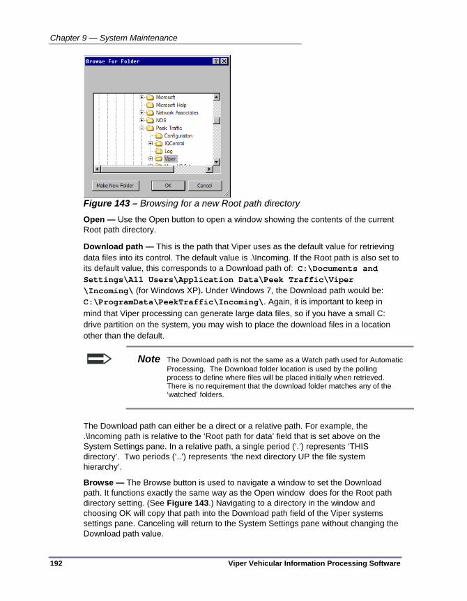
Chapter 9 — System Maintenance
192 Viper Vehicular Information Processing Software
Figure 143 – Browsing for a new Root path directory
Open — Use the Open button to open a window showing the contents of the current Root path directory.
Download path — This is the path that Viper uses as the default value for retrieving data files into its control. The default value is .\Incoming. If the Root path is also set to its default value, this corresponds to a Download path of: C:\Documents and Settings\All Users\Application Data\Peek Traffic\Viper \Incoming\ (for Windows XP). Under Windows 7, the Download path would be: C:\ProgramData\PeekTraffic\Incoming\. Again, it is important to keep in mind that Viper processing can generate large data files, so if you have a small C: drive partition on the system, you may wish to place the download files in a location other than the default.
Note The Download path is not the same as a Watch path used for Automatic Processing. The Download folder location is used by the polling process to define where files will be placed initially when retrieved. There is no requirement that the download folder matches any of the ‘watched’ folders.
The Download path can either be a direct or a relative path. For example, the .\Incoming path is relative to the ‘Root path for data’ field that is set above on the System Settings pane. In a relative path, a single period (‘.’) represents ‘THIS directory’. Two periods (‘..’) represents ‘the next directory UP the file system hierarchy’.
Browse — The Browse button is used to navigate a window to set the Download path. It functions exactly the same way as the Open window does for the Root path directory setting. (See Figure 143.) Navigating to a directory in the window and choosing OK will copy that path into the Download path field of the Viper systems settings pane. Canceling will return to the System Settings pane without changing the Download path value.

System Settings
Viper Vehicular Information Processing Software 193
Units Selection These global units settings are used to define the ADR studies that are created in the Devices pane
Speed Units — Speed can be defined in ADR studies as either mph (miles per hour) or kph (kilometers per hour.)
Length Units — Lengths can be defined in ADR studies as either meters or feet. Length values are used in bins where Length, Headway and/or Gap are used as one of the binning dimensions.
Weight Units — Weight can be defined in ADR studies to use either KIPS (kilopounds, i.e. thousands of pounds) or Tonnes (metric tons, i.e thousands of kilograms.) Weight is used in any study where Gross, Single, Tandem, and/or Triple are used as a binning dimension.
System Archiving System Archiving is the process of creating a file backup of all of the current settings stored in Viper. Think of it as a ‘Viper System Backup’. A System Archive does not store the data being managed or processed by Viper, but it does store the system settings, device and communications channel instances, study definitions, export definitions, and automatic processing flows.
Figure 144 – System Archiving section of the System Settings pane
Archive path — The archive path is the location on your system or network where the backup files are stored when you perform a System Archive. This can be either a relative or direct path. If relative, the path will be relative to the Root path directory defined at the top of the System Settings window.
Archive button — Use this button to tell Viper to store all of its current configuration settings to a new directory in the Archive path folder. The folder and files will be

Chapter 9 — System Maintenance
194 Viper Vehicular Information Processing Software
tagged with the current date. If more than one archive are performed on a given day, the date will be augmented with the time of the archive, in 24 hour (military time) format. (e.g. ‘Settings Archive 2010 Oct 20 at 14_33_25’ to indicate the archive was performed at 2:33 pm.) As soon as the backup is complete, you will see the new available archived configuration at the bottom of the list in the window below the button.
Available Archived Configurations — These show all of the available configuration backups that have been performed for this Viper system. To restore a particular archive, highlight it and press the Restore button.
Restore button — This button is used to trigger a retrieval of all of the configuration settings from a System Archive backup, where they will overwrite all of the current settings in Viper.
Caution Restoring a Viper System Archive instance will overwrite all current
settings in Viper, including any Device, Comms Channel and Automatic Processing changes that have been made since the archive was performed.

Activity Logging
Viper Vehicular Information Processing Software 195
ACTIVITY LOGGING Viper is pre-configured to automatically record key activity to a ‘system log’. The System Log can be viewed by opening the Viper interface and selecting System Log. The last 90 days of activity since Viper was installed will appear, with the most recent activity showing up at the top of the list. (Refer to Figure 145)
Figure 145 – Viper System Log view
There are three levels of message displayed, depending on the severity of the situation that caused them:
Table 7 – Message types in Viper system log
Icon Message Severity
Informational message
Warning message
Error message

Chapter 9 — System Maintenance
196 Viper Vehicular Information Processing Software
The System Log records the following types of activity:
Table 8 – Possible System Log messages
Message Generated by module: A fault was observed in {operation}. Automatic Processing A valid county must be specified for {site} {station} Automatic Processing A valid US state must be specified for {site} {station} Automatic Processing Automatic processing started. Automatic Processing Automatic processing stopped. Automatic Processing Cannot process TMG export for {site} {station}. One or more of the required fields are missing.
Automatic Processing
File is older than the maximum age and cannot be processed.
Automatic Processing
No direction information is available for {site} {station}. Automatic Processing Of {x} devices polled, {y} reported warnings and {z} failed. Autopolling Study {x} contains an unsupported heading type. No PRN file will be generated.
Automatic Processing
Task {x} completed. Scheduler Task {x} failed ({reason}). Scheduler Task {x} started. Scheduler The directory listing contained {N} invalid entries. Autopolling The file is an unsupported type and cannot be exported to TMG format.
Automatic Processing
The number of lanes configured for the site does not match the number of lanes in the file.
Automatic Processing
Too many bad directory entries. Unable to continue. Autopolling
Note Viper has an additional layer of logging that is intended for application debugging. The conditions which generate events in the Viper debug logs, which are ASCII text files, are hard coded into each of the Viper executable modules. The debug logs can be viewed by opening a Windows Explorer window and navigating to the folder that you set to be the ‘Root path for data’ on the System Settings pane. The default location for these files is: C:\Documents and Settings\All Users\Application Data\Peek Traffic\Viper\ (Windows XP) C:\ProgramData\Peek Traffic\Log (Windows 7)

Activity Logging
Viper Vehicular Information Processing Software 197
Refreshing the Log View The System Log view is updated whenever one switches to that pane within Viper, however if one wishes to update the list for the most recent logged activity since the pane was open, merely click on the Refresh button. The Refresh button is located in the upper left corner of the System Log work area.
Figure 146 – System Log refresh button
Configuring System Logs There are currently no options available to configure the Viper system logs.
Refresh button

Chapter 9 — System Maintenance
198 Viper Vehicular Information Processing Software
TROUBLESHOOTING If you are encountering problems with your installation of the Viper software, please gather the version information of the software, the information about your computer itself, and follow the suggestions on the Viper Troubleshooting checklist below.
Viper Version Information Especially when contacting Peek Technical support about your software, it is a good idea to have the software version information on hand. All of the version details about the various modules of the software are visible on the Viper About screen, which can be accessed in a couple of ways:
Go to the Help menu and select About
Click on the About tab in the navigation bar
Figure 147 – Viper About screen

Troubleshooting
Viper Vehicular Information Processing Software 199
Technical Assistance For help tracking down the source of a problem you are having with Viper, please contact the Peek software technical support team using one of the following methods:
Contact Information Hours of Operation Toll free in the U.S.: (800) 245-7660 phone: (941) 845-1200 fax: (941) 845-1504 2906 Corporate Way Palmetto, FL 34221 email: [email protected] website: www.peektraffic.com
M-F, 8am-5pm, Eastern Time (U.S.)
Troubleshooting Checklist If Viper is not performing as expected in some way, refer to the problem assessment, diagnoses, and possible actions listed in the following troubleshooting checklist.
Table 9 – Troubleshooting checklist
Problem encountered Possible Cause Suggested Action or Workaround Version of operating system is not supported
Make sure the computer is running Windows XP, Windows Vista, or Windows 7 (Enterprise or Professional level versions only.)
Installer does not have rights to install software on the system
Change login user or add installation rights to the user account
Installer does not have rights to create files and folders at the selected location on the hard drive
Change the installation location or add rights to the selected directory to the installer’s user login account
Insufficient space on the hard drive Select a different installation drive or clear enough space to allow Viper to be installed.
Installation cannot be completed successfully
Failure to accept license agreement The software cannot be installed unless the installer accepts the Viper end-user license agreement. Navigate and find the viper.exe file on your system. Create a new shortcut on your desktop and/or in the Windows Start menu to the new location.
Cannot launch the application
The application is not where the Viper shortcut expects it to be
OR relink the shortcut icon to the Viper application by right-clicking on the Viper icon and choosing Properties. Type in the correct Target location for the application, or use the Find Target button to browse to the application file. (Default location of the app .exe file =

Chapter 9 — System Maintenance
200 Viper Vehicular Information Processing Software
Problem encountered Possible Cause Suggested Action or Workaround C:\Program Files\Peek Traffic\Viper\bin)
Logged in user does not have rights to run the Viper application
Modify the user account or login as a different user Undelete the files from the Windows Recycle bin
Viper application files or support files have been deleted or corrupted
or Reinstall Viper from the installation disk
User rights have been modified so that the user does not have access to the viper root data directory.
Make sure that the logged in user account can access the root data directory (as listed in the Viper System Settings panel.)
Root data directory is on an un-mounted drive or network location
Make sure all mounted and network drives are available as expected. If not, attempt to login again, or investigate the servers or drive hardware.
Viper environment variable pointing to data files has been changed or corrupted
Check that the Windows environment variable PEEK_VIPER_V1_0_0_DATA is pointing to the correct root data directory in your system. If not, try setting the root directory (using the Viper System Settings panel) away from the desired directory and then back to reset the variable.
Devices, Comm channels, or Auto-processing information cannot be added to Viper
Corrupted data file Viper stores all configuration information, with the exception of scheduled event activity, in a file in its root data directory called Viper.settings. Attempt to restore this file from a system backup. If that fails, you may need to restore Viper from an Archived backup configuration to another location.
This indicates that the data file is either missing or somehow unavailable, when Viper looks for it, so it automatically recreates the file, but blank. Check to see if the Viper.settings file has been moved or deleted from the Viper root data location.
Restore Viper.settings from a system backup or failing that, a Viper configuration archive.
Corrupted data file Attempt to restore the file Viper.settings from a system backup to the Viper root data directory. If that fails, you may need to restore Viper from an Archived backup configuration to another location.
Viper root data directory has been moved to a location where the user does not have rights
Verify that the Rood directory for data setting (on Viper’s System Settings panel) is pointing to the proper location on your system or network.
Previously entered device, comms channel or auto-processing information is not appearing in Viper, but new data can be entered.
Corrupted Viper application files Uninstall and reinstall the Viper

Troubleshooting
Viper Vehicular Information Processing Software 201
Problem encountered Possible Cause Suggested Action or Workaround application.
ADR Comm ID set incorrectly For communications to be successful, the Comm ID stored in Viper must match the Comm ID stored in the ADR device.
Device has no power Recharge the battery or restore line power to the unit
Loose connectors Verify that all connections are firmly seated at all connection points between the Viper PC and the field device
Faulty comms settings Verify that all values for the desired channel are set up correctly, such as the IP address for an Ethernet channel and the baud rate for a Serial connection. Test the PC port with another device or a local device to see if it is functioning.
Unable to access port on the PC
Some machines allow ports to be blocked by user account. Verify that the user is granted access to the physical port on the computer.
Faulty port on the device Test the device using a local connection such as a direct-to-PC connection or a local modem
Cannot communicate with device over the selected channel
IP connection blocked by Firewall Most organization have a firewall on their Ethernet communications to outside facilities. If a firewall exists between the Viper PC and the device, make sure that the firewall has been configured to allow this communication to occur.
Cannot load device configuration from a file
File is corrupted Attempt to recreate the file from the device, or restore from a backup copy.
File is not a valid device configuration file
Choose a different file, or regenerate the file from the device source.
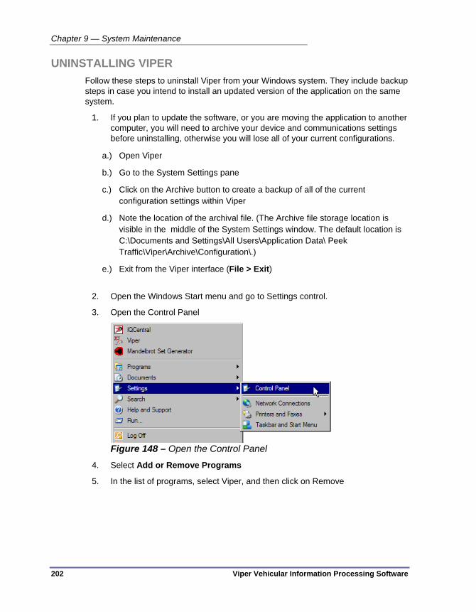
Chapter 9 — System Maintenance
202 Viper Vehicular Information Processing Software
UNINSTALLING VIPER Follow these steps to uninstall Viper from your Windows system. They include backup steps in case you intend to install an updated version of the application on the same system.
1. If you plan to update the software, or you are moving the application to another computer, you will need to archive your device and communications settings before uninstalling, otherwise you will lose all of your current configurations.
a.) Open Viper
b.) Go to the System Settings pane
c.) Click on the Archive button to create a backup of all of the current configuration settings within Viper
d.) Note the location of the archival file. (The Archive file storage location is visible in the middle of the System Settings window. The default location is C:\Documents and Settings\All Users\Application Data\ Peek Traffic\Viper\Archive\Configuration\.)
e.) Exit from the Viper interface (File > Exit)
2. Open the Windows Start menu and go to Settings control.
3. Open the Control Panel
Figure 148 – Open the Control Panel
4. Select Add or Remove Programs
5. In the list of programs, select Viper, and then click on Remove

Uninstalling Viper
Viper Vehicular Information Processing Software 203
Figure 149 – Removing the Viper application
6. Follow the dialog boxes to finish removing the application. This will not delete your directory of archived configuration data.

Chapter 9 — System Maintenance
204 Viper Vehicular Information Processing Software

Viper Vehicular Information Processing Software 205
Glossary
Many terms are used commonly in traffic data collection. Unfortunately, sometimes the same word is used to mean different things. This list contains the terms we use, together with “our” definitions as used in this manual.
2 RT – A unit will be equipped with two individual inputs for pneumatic road tube axle sensors
4 RT – Traffic Recorders equipped with four individual inputs for pneumatic road tube axle sensors.
AC Adapter Charger – Step-down transformer used to charge the internal battery of an ADR-1000 or 2000.
ADR 1000 Plus – Self-Contained Lightweight Portable Traffic Counter / Classifier expandable to support one additional sensor module.
ADR 2000 Plus – Self-Contained Portable Traffic Counter / Classifier expandable to support three additional sensor modules.
ADR 3010 Plus – Permanent 10” wide Rack-based Traffic Counter / Classifier which has the capability of supporting three sensors modules and two additional smart modules.
ADR3019 Plus – Permanent 19” wide Rack-based Traffic Counter / Classifier which has the capability of supporting eight sensors modules and two additional smart modules.
ADR 6000 – Permanent High accuracy Rack-based Traffic Counter / Classifier using only loops which can be used where traffic conditions range from free-flow to Stop and go. Uses Idris technology to separate signals that are overlapping or closely spaced and thus otherwise difficult to interpret.
ADR Plus RS232 Module – Module has two additional RS232 Communication ports available for the ADR3000 only, Supports comm. 2 and 3 with baud rates up to 115200.

Glossary
206 Viper Vehicular Information Processing Software
Air Switch – Pneumatic Switch sensor used to sense the incoming air pressures change from a road-tube.
AO – Alarm Output can be used to trigger a relay or similar device, available only on the ADR-2000 and 3000.
Armed – Is displayed on the ADR display when the unit has a completed program and is waiting for the next full interval to begin recording.
Array – When referring to an array, we mean a sensor, or group of sensors which work together to determine information about the vehicles passing over them. An array can span one or more Lanes, depending on array type, but are usually only one lane per array. Each array will assign a Flow number to any vehicles detected upon it. Some arrays, for example the single loop or single axle arrays, can only determine a single Flow. Others, such as the Tube-and-a-half or two tube classification arrays can determine more.
Axle Class – Axle Class is vehicle type classification based on the number and spacing of axles on a vehicle. The most common reference for this is published as Scheme “F”. See also Class or Classification
AxleLight – Is an infrared axle sensor for use with the ADR Plus traffic recorders. The AxleLight allows users to perform traffic studies without venturing into or crossing the roadway.
Bending Plates – Bending Plate WIM systems utilize plates with strain gauges bonded to the underside. As a vehicle passes over the bending plate, the WIM system analyses the strain measured by the strain gauges and calculates the dynamic load. The static load is estimated using the measured dynamic load and calibration parameters.
Bins – As used when saying “the number of speed bins. A bin can be thought of as a container for information or data. Bins are established by defining their limits. An example of a bin definition is contained in the following statement: “All of the cars traveling at (or above) 30 miles per hour and less than 35 miles per hour are recorded in this bin”. For any one study session the ADR can use up to 3,375 bins at once. Studies are usually described by the number of bins utilized, i.e.: 15 classes x 4 lanes is a total of 60 bins.
Channel – Channel is similar in use to the word “lane” or “array” but is less specific and may have no physical reference. The data from one lane is normally collected via one array and is then often stored in one channel. A channel has the capability of either separating the data from one array or lane (by “flow” direction) or can combine the data from a set of arrays into one total. See also: CHANNEL MAPPING and SUMMATE CHANNELS.
Channel Mapping – The CHANNEL MAPPING setting causes the count of vehicles to be stored in one or more “channels”. The CHANNEL MAPPING option has the following settings (SEPARATED and FORWARD ONLY are not available for array types that cannot determine a vehicle’s direction):

Glossary
Viper Vehicular Information Processing Software 207
• COMBINED. This causes the count of vehicles from each array to be stored in a channel. The count is incremented each time a vehicle passes the array, no matter in which direction it is traveling. Channel 1 is for array 1, Channel 2 for array 2, etc.
• SEPARATED (by direction). This causes the count of vehicles from each array to be stored in two channels. Channel 1 will contain the count of vehicles that are traveling in the forward direction across array 1. Vehicles that are traveling in the reverse direction of array 1 will be contained in Channel 2. Note that if more arrays are used, each subsequent array will have two channels associated with it. The forward direction is defined as those vehicles that are traveling from the lead sensor to the lag sensor.
• FORWARD ONLY. Vehicles traveling in the reverse direction are ignored. The count is incremented each time a vehicle passes the array in the forward direction only. Each array will have only one channel associated with it.
• USER DEFINED. This enables you to specify the number of channels to create (the maximum, which is displayed on the screen, is dependent on the number of arrays and the array type). Once you have specified the number of channels, you can assign each array’s count of vehicles to a particular channel. The “+” forward direction is defined as vehicles traveling from the lead sensor to the lag sensor. The “-“ reverse direction is defined as vehicles traveling from the lag sensor to the lead sensor. Once the channel assignments have been specified, the number of bins in the heading of the record can be determined. The number of bins is dependent on whether NO or YES is selected for the SUMMATE CHANNELS option, which is available for the FORWARD ONLY and COMBINED options. If NO is selected, or the option is SEPARATED or USER-DEFINED, the number of bins in heading 1, 2 or 3 is the same as the number of channels. However, if YES is used, you can specify the number of bins to use and the channel numbers to assign to each set of bins.
Class – In the ADR the word CLASS is used as a menu prompt for the classification of vehicles according to a preset vehicle classification scheme. The defining criteria of a scheme are called a ClassTree or Class table. The best known and most widely used scheme in the world today is referred to as Scheme “F” which uses the number, spacing and grouping of axles to assign each vehicle to one of thirteen definitions of vehicle type. Scheme“F” is the default scheme in the ADR as supplied, with the addition of a fourteenth “Other” type and a fifteenth category for “unclassified”. ADR operators can and are encouraged to determine the best scheme for local operations and install it in the ADR. This is a very powerful feature of the ADR and operators can apply additional criteria such as length to fine tune their local scheme.
Class Tree: – A ClassTree is an advanced way of determining what type of vehicle has crossed the ADR’s sensors. Unlike a simple lookup table, where there is a rigorously defined set of parameters, a ClassTree is implemented as a series of “test and branch” operations. This makes it possible to create custom classification schemes that would be difficult, or impossible, for a lookup table. A ClassTree can also be optimized so they require less system resources than the equivalent table.
Classification – The dictionary defines the act of classification as the assignment of “things” to groups as determined by criteria. The ADR can assign vehicles to groups

Glossary
208 Viper Vehicular Information Processing Software
(which are called “Bins”) based on a variety of criteria. The most commonly used criteria are CLASS (see above definition), CHANNEL, SPEED, LENGTH (either wheelbase or chassis), GAP, HEADWAY or GROSS WEIGHT. In setting up the ADR, operators can set the limits of the criteria to be used, for example in classification by SPEED, operators can specify the number of “Speed Bins” and then can specify the limits of each of the bins as 0 to 20 mph and 20 to 30 mph and so on.
Cold Boot – This operation allows a user to reset a recorder to its factory defaults values.
Comm ID – Each ADR has the option of setting a Comm ID from 1 to 65534 this option is used when several units are connected to the same communication device and a user needs have only one unit a time to answer when a command is set to all units.
Continuous File – Is a binned or PVR file which has one header that includes all set-up information including the start date and time and will not include an end date time until a user ends the current recording session. This recording session could span several days, weeks or months depending on the amount of time a users desire to allow the recorder to continue to recorder without stopping or ending the recording session.
CPU Module – The ADR’s Central Processing Unit, Plus units are equipped with 2Mb. of onboard memory; non-Plus units are equipped with 256K of onboard memory.
CPU Mother Board – CPU Mother board contains the connectors for attaching a CPU Module and additional smart modules used by the ADR3000.
Daily Files – Is a binned or PVR file which is one file with a file header for each day that includes all set-up information including the start and end date and time for each day. These files will have a maximum of 24 hours of data from midnight to midnight or until a user has stopped the ADR from recording data.
DB9 – Is a D style 9 pin connector used on the ADR3000 as a standard RS232 connector.
Debounce – Debounce value ensures that phantom signals in tubes or piezo sensors are not regarded as axles. It is the time set to ignore any pulse after valid axle detection. The range of possible values is from 1 to 998 msec. If the ADR is undercounting, reduce the debounce time; if the ADR is over-counting, increase the debounce time.
DST – Is the Daylight Saving Time adjustment, users have the option to allow the ADR to automatically adjust for the new time.
Factory Default Settings – These settings are the default settings as defined by the firmware which have been defined and set by Peek Traffic Corp. The default value settings may be different from one version firmware to another.

Glossary
Viper Vehicular Information Processing Software 209
Flash Upgradeable Firmware – This feature enables users to change versions of ADR Firmware by using a simple Firmware Upload Utility which requires no disassembly or hardware changes to the unit.
Flow – When any vehicle crosses any sensor array, it is assigned a “flow” indicating the vehicle passage. The assigned flow on single sensor arrays is a + (plus). Arrays with two sensors in the same lane assign either a (+) plus or a (-) minus to a vehicle passage as determined by the sequence of sensor activations. (i.e.: Travel from A to B is assigned (+) flow and travel from B to A is assigned (-) flow. This is commonly called direction of travel. The ADR also makes use of more complex sensor arrays, such as the four roadtube array, which can also provide a lane assignment to a vehicle passage. When monitoring the four roadtube array in the VEHICLE MONITOR you will see (*) and (-) assigned to vehicles in the near lane, and in the far lane vehicles will be assigned as (2+) or (2-). The ADR allows you to segregate (or combine) vehicles into separate data “channels” and “bins” by flow assignment in CHANNEL MAPPING.
Gap – Gap is the time (in seconds) between the trailing axle of the first vehicle and the leading axle of the second vehicle going in the same direction when using piezo or tube sensors, or the time between the rear of one vehicle and the front of the following vehicle when using loops.
GPS – Global Positioning System
Headway – Headway is the time (in seconds) between the leading axles of two vehicles going in the same direction when using piezo or tube sensors, or the time between the front of one vehicle and the front of the following vehicle when using loops.
HPMS — The HIghway Performance Monitoring System is a set of reporting standards used by the U.S. Federal Highway System. States follow these guidelines very carefully, as the resulting data is used to divide the federal highway moneys among the several states.
Idle – The ADR is in a state where there is no start time or date programmed.
Inductive Loop (Loop) – An inductive loop detector is the (Loop and lead-in wire) which forms an electrical circuit in each lane of traffic which are then connected to a loop module to detect vehicle traffic.
IOC – Is a type of firmware reset performed by ADR CPU known as an Illegal Operation Code. An IOC reset code can be viewed through the ADR UI under Last Reboot.
JR 161 – Is a lightweight semi-portable volume traffic recorder which provides accurate traffic volumes using inductive loops.
JR ADR RT – Is a lightweight portable road tube volume traffic recorder which provides accurate traffic volumes with a built-in timer.
Keyboard and Display (KD) – Are the 16 key keypad and interactive 20 characters by 4 line LCD.

Glossary
210 Viper Vehicular Information Processing Software
Kistler Sensor – Quartz piezo sensor that is used to measure axle vehicle weights under rolling traffic conditions.
KIPS – A unit of weight equal to 1000 pounds (453.6 kilograms).
Lane – The term "lane" is used to refer to a physical lane on the road, typically delineated from the rest of the road with a painted line or physical barrier.
LCD – The ADR is equipped with a 20 character by 4 line Liquid Crystal Display.
Length – Length is the total wheelbase length when measured by piezo or tube sensors, or the overall length (chassis) when using loop sensors.
Load Cells – A load cell is a transducer that converts a load acting on it into an analog electrical signal. This conversion is achieved by the physical deformation of strain gages which are bonded into the load cell beam and wired into a wheatstone bridge configuration. Load Cell WIM systems utilize load cells scales to detect axles and weigh both the right and left side of the axle simultaneously. As a vehicle passes over the scales, the system records the weights measured by the scale and obtains an axle weight and gross weight.
LRS — The Linear Reference System is a standard used by the U.S. Federal Highway Administration, in conjunction with its HPMS reports, to identify roadways by their functional classifications. The LRS uses classifications such as ‘urban’ versus ‘rural’ and labels roadways with common terms such as ‘major collector’ and ‘principal arterial’.
Marked Files – Are Binned or PVR files that have previously been downloaded or marked as a read file and will be indicated as an open book when viewed by the ADR Commander.
Memory – Is the available room used by ADR for storing Bin, PVR and Set-Up files in the ADR.
Modem LPM – Is a low powered device that enables the ADR to transmit information over telephone cables to a remote computer.
New Files – Are Binned or PVR files that have never been downloaded and marked as read file, these files are shown as closed book in the ADR Commander which indicates that the file has never been read before.
NPA – Is a type of reset of the ADR CPU firmware, which has been performed by the ADR and is logged and displayed as Null Pointer Assignment.
Occupancy – The percent of time that a loop is occupied during a given period of time, for example for a 60 second period 30 seconds is considered 50% occupied.
Old Files – Are Binned or PVR files that have previously been downloaded and will be indicated as an open book by the ADR Commander.
PCMCIA Module – Optional Memory expansion Port that is used on an ADR to accept an S-Ram PCMCIA Card.

Glossary
Viper Vehicular Information Processing Software 211
PCMCIA Card – Removable S-Ram memory card which is used in the PCMCIA Module to either expand the memory of the ADR or to collect and remove files from an ADR.
Per-Vehicle-Record (PVR) – Per-Vehicle-Records are individual records of each vehicle that passes over sensors that are interfaced to the ADR. Each record can include items such as (if the ADR is equipped and configured for) Number of Axles, Speed, Class, Headway, Gap, Vehicle Status, Loop Length, Total Wheelbase, Axle Spacing, Gross Weight, Axle Weights, Temperature and Alarm codes.
Piezo Axle Sensor – An in the road or over the road axle sensor that is used to sense axles for vehicle classification, weigh in motion and counting
PMU Module – Is a Power Management Unit Module which is used to convert 120Vac or 12Vdc to 6Vdc for use by an ADR3000 unit only
Power Options
Option 0: – Accepts 6 Vdc power input only
Option 1: – This power option is supplied with an PMU, 110Vac step-down transformer and a 12 Vdc Standby battery, this option is used where AC power is available and the user needs to have a Standby battery which can supply power during power outages.
Option 2: – No longer available:
Option 3: – No longer available:
Option 4: – This power option is supplied with an PMU, which will accept power from a 12Vdc power source this option is used where a customer is using a 12Vdc Power supply (for example 12Vdc Solar) which will supplies 12Vdc power to the PMU.
Road Tube – A pneumatic axle sensor that is used as part of portable traffic data collection system.
SA58-P Module (8 Channel Piezo Module) – Is a low current eight channel piezo sensor detector which is designed to be used with Piezo axle sensors.
SA74-P Module (4 Channel Piezo Module) – Is a four channel piezo sensor detector which is designed to be used with Piezo axle sensors.
SC514-P Module (14 Channel Contact Module) – Is a fourteen channel contact closure input module which is designed to accept a contact closure from some other type of sensing device, for example (Loop detector, RTMS, Radar etc).
Sensor Modules – Sensor Modules for the ADR include all of the following (SA58-P, SA74-P, SC514-P, SL58-P, SL74-P and SW58-P).
Sensor Mother Board (MB) – The Sensor Mother board contains the connectors for attaching additional Sensor Modules which are used by the ADR.
Glossary
212 Viper Vehicular Information Processing Software
ADR1000 supports one sensor mother board which can support one sensor module
ADR2000 sensor mother board is manufactured as part of the CPU mother board and can support three additional sensor modules.
ADR3000 supports three, three position Sensor Mother Boards which can support a total of nine additional sensor modules.
Serial Cable to Computer (Direct Connect Cable) – This cable is used between the Serial Port of the ADR and a Computers Serial Port.
1000/2000 Cable equipped with a CPC connector to DB9
3000/6000 Cable equipped with a DB9 to DB9
Serial Cable to Modem – This cable is used between the Serial Port of the ADR and a modem.
1000/2000 Cable equipped with a CPC connector to DB25
3000/6000 Cable equipped with a DB9 to DB25
Set-Up File – Are unique Custom SetUps or instructions that have been created by a user which can be saved, copied and reloaded to other ADRs. Loading a “setup file” is faster and easier than creating a new Custom Set Up. Users have thee option to Save and Store a Set Up File, each option will contain more Configuration information SetUp, SetUp+Class Tree or a complete BackUp of the configuration.
SHRP — The Strategic Highway Research Program of the U.S. Federal Highway Administration. In their own words, “In 1987, the U.S. Congress authorized the Strategic Highway Research Program (SHRP) - a five-year, applied research initiative - to develop and evaluate techniques and technologies to combat the deteriorating conditions of the nation's highways and to improve their performance, durability, safety, and efficiency.”
Single – Single is the weight on a single axle of the vehicle.
Site – The term “Site” is typically used to refer to the physical location of traffic data collection equipment. Some examples would be “Corner of Route 301 and Smith Road”, or “M 25 Junction 14”. The “Site” and “Station” information can be used in combination to represent or designate a single piece of data collection equipment and the data which is collected from it. Under some circumstances, “Site” may not specify a single road or intersection. In such cases, data collected from each unit within the site is used to build a picture of the traffic flow through the site. By default from the factory, the electronic serial number of each ADR is shown as the Site ID.
SL58-P Module – Is a low current eight channel modular inductive vehicle detector designed primarily for traffic data monitoring applications, using the `EURO card' printed circuit board outline.
Glossary
Viper Vehicular Information Processing Software 213
SL74-P Module – Is a four channel modular inductive vehicle detector designed primarily for traffic data monitoring applications, using the `EURO card' printed circuit board outline.
SL – Integrated lid Solar Panel can only be fitted on the ADR1000 or 2000.
Smart Modules – Smart Modules for the ADR includes the following PCMCIA, Dual Comms and the CPU Modules.
Speed – Speed is the speed of the vehicle and may be displayed as either miles per hour or kilometers per hour.
Station – The “Station” is sometimes used to distinguish between pieces of data collection equipment at the same physical location (or “Site”). When setting up an ADR for operation at a location, you will be prompted to enter in a Site and a Station identifier. You should feel free to set the Station field to contain any useful reference information desired in conjunction with the Site field.
StopWatch – Is an optional ADR Firmware feature which allows the ADR to perform twin operations, one to calculate and store all of the normal historical studies and one to calculate Average Speed, Volume and Percent Occupancy for each lane in a separate selectable interval from 10 seconds to 60 minutes.
Study – Each ADR has the ability to manage eight different data studies at one time, each study will be saved in its own data file. Depending on the sensor arrays selected a user may have the following surveys to select from (Speed, Lane, Class, Headway, Gap and WIM).
Surge Panel – Is a protection device designed to protect the ADR from incoming surges; the Surge Panel is normally used to protect inputs from communication lines, power, piezo and loop sensors.
SW58-P Module – Is an eight channel Weigh-In-Motion module which interfaces to either class 1 Piezo or Kistler axle sensors.
Tagged (Marked) Files – Are Binned or PVR files that have been selected or sometimes referred to as (Marked) to either be collect, deleted or moved from the specific memory media.
Tailgating Algorithm – Is a unique algorithm that enables the ADR to determine when four or more axles are detected and if those axles belong to one vehicle or to two separate vehicles.
Tandem – Tandem is the weight on a group of two axles of the vehicle. The group is defined by the CONFIGURE/CALIBRATION/ MAX LENGTHS option.
Triple – Triple is the weight on a group of three axles of the vehicle. The group is defined by the CONFIGURE/CALIBRATION/MAX LENGTHS option.
TONNES – A unit of weight equivalent to one metric ton, which is 1000 kilograms or 2204.62 pounds.
TOPS – Traffic Operations and Planning Software

Glossary
214 Viper Vehicular Information Processing Software
TMG — The vehicular study data reporting standard of the United States Federal Highway Administration, as defined in their Traffic Monitoring Guide.
UI – Refers to the User Interface, this includes the Keyboard and the LCD display.
User Reboot – Is a type of reset of the ADR CPU firmware which has been performed by a user and is displayed as a User Reboot.
Volume – Is the vehicle count, in the SETUP procedure, volume is called channel, since the volume counts can be channeled.
Weight – Weight is the total gross weight of the vehicle.
Weigh-In-Motion (WIM) – Is the practice of weighing a vehicle as it moves along a highway system.
Wrap Files – Allows the ADR to delete the oldest files first to obtain room in memory when needed to continue recording the most current recording period. User need to use caution when recording continuous files, memory can becomes full and if the ADR is set to wrap files it will delete the currently recording file when the memory becomes full.
Viper Vehicular Information Processing Software 215
Index
.
.bin files .................................................................. 9
.prn files.................................................................. 9
.pvr files.................................................................. 9
.stp files .................................................................. 9
1 14 channel contact module................................. 211
2 2 RT.................................................................... 205
4 4 channel piezo module...................................... 211 4 rt....................................................................... 205
8 8 channel piezo module...................................... 211
A about ..................................................................... 19 about screen........................................................ 198 AC adapter charger............................................. 205 acceleration........................................................... 83 accessing services................................................. 22 account.................................................................. 12 acoustic ................................................................. 88 action library......................................................... 96 action parameters................................................ 102
activating an xml export plan .............................164 activating prn export plan ...................................159 activating the report plan ....................................181 activating TMG export plan ...............................173 activity logging ...................................................195 add a device button ............................................... 54 add button ............................................................. 78 add channel button................................................ 33 add new merged site ...........................................108 add new source site.............................................109 add task button....................................................139 adding a channel ................................................... 35 adding a device ..................................................... 57 adding a routing rule............................................. 48 adding a scheduled task ......................................146 adding a step to a workflow.................................. 95 adding a write prn action ....................................151 adding a write xml action ...................................160 adding an ADR-6000 device ................................ 59 adding links to a workflow ................................... 93 adding the generate report action .......................175 adding the write TMG action .............................166 additional settings ................................................. 44 address ............................................................2, 199 address bar ......................................................18, 20 address settings ..................................................... 46 adjust for DST.....................................................106 adjusting binned data for daylight savings time.131 ADR firmware ...................................................... 74 ADR manuals.......................................................... 2 ADR plus RS232 module ...................................205 ADR-1000 plus...................................................205 ADR-2000 plus...................................................205 ADR-3000 plus...................................................205 ADR-3019 plus...................................................205 ADR-6000...........................................................205
Index
216 Viper Vehicular Information Processing Software
file dates .......................................................... 84 ADR-6000 devices ............................................... 52 ADRs ...................................................................... 6 advanced editing
communications .............................................. 34 advanced editing of scheduled events................ 143 advanced settings.................................................. 46 advanced timing settings ................................ 43, 44 airswitch ............................................................. 206 AO ...................................................................... 206 apply ..................................................................... 34 apply button.......................................................... 66 apply task .......................................................... 147 apply to task........................................................ 142 archive button ..................................................... 193 archive modified files......................................... 107 archive path ........................................................ 193 archive source files............................................. 108 archiving ............................................................. 193 Armed ................................................................. 206 Array................................................................... 206 array selector checkboxes..................................... 81 ASCII...................................................................... 9 assumptions ............................................................ 1 ASTM standard .................................................... 87 AT......................................................................... 44 at the following local time.................................. 141 auto answer off string........................................... 45 auto answer on string............................................ 45 automatic processing
overview .......................................................... 92 auto-polling summary report.............................. 174 auto-processing
action library.................................................... 96 color coding in the plan area background ..... 103 creating a plan ............................................... 119 launching ......................................................... 94 panel ................................................................ 93 restart ............................................................. 122 work environment ........................................... 95
auto-processing service .................................. 25, 92 available archived configurations ...................... 194 available communications options ....................... 30 available name components ............................... 111 AVCC product manager..................................... 174 AVI ....................................................................... 88 Axle Class........................................................... 206 axle spacings......................................................... 82 axle weights .......................................................... 82 Axlelight ................................................................. 2 AxleLight............................................................ 206
B backing up Viper configurations........................ 193 battery voltage .................................................... 145
baud rate..........................................................43, 45 bending plate.........................................................88 Bending Plates ....................................................206 bin files....................................................................9 bin type..................................................................78 binned data ..........................................................113 binned tab..............................................................77 Bins .....................................................................206 block diagram .......................................................16 browse button......................................................192 buffer size........................................................43, 44
C calibration methods...............................................88 capacitance mat.....................................................88 capacitance strip....................................................88 change .................................................................191 channel ..................................................................68 Channel ...............................................................206 channel # ...............................................................76 channel ID.......................................................37, 38 Channel Mapping................................................206 channel parameters ...............................................43 charge current .....................................................145 check device date and time ...................................73 check host name button ........................................70 check menu ...................................................51, 135 city.........................................................................66 class...............................................................81, 207 class by channel report................................174, 184 class report ..................................................174, 182 class tree..............................................................207 classification .......................................................207 classification algorithm.........................................86 classification scheme ............................................86 cold boot..............................................................208 color coded connection points ..............................93 color coding
auto-processing plan area ..............................103 COM port ........................................................43, 46 combined.............................................................207 comm ID .............................................................208 comma-delimited ....................................................9 command line utility .............................................16 communications
adding a channel ..............................................35 available options ..............................................30 deleting a channel ............................................41 editing a channel ..............................................39 overview...........................................................30 parameters ........................................................43 summary view..................................................32
communications channels panel ...........................31 communications ID...............................................69 complete install .....................................................13
Index
Viper Vehicular Information Processing Software 217
computer management ......................................... 23 concurrent route number ...................................... 90 concurrent route signing....................................... 90 configure channel ................................................. 68 configuring a merged site................................... 123 configuring auto-processing................................. 92 configuring devices for TMG export ................. 170 configuring file names........................................ 110 configuring IP routing .......................................... 48 configuring system logs ..................................... 197 connecting steps in a plan .................................... 98 connection
deleting a workflow connector...................... 102 connection point ................................................... 99 connection tab ...................................................... 68 connections........................................................... 30 contact info ..................................................... 2, 199 continuous file .................................................... 208 copy settings from ................................................ 64 county ................................................................... 67 cpu module ......................................................... 208 cpu mother board................................................ 208 creating a sub-folder for each............................. 171 creating an auto-processing plan........................ 119 crystal reports ..................................................... 174 current................................................................. 145 current firmware version on the device ............. 145 current merged site settings................................ 109 current recording files ........................................ 144 custom directional codes .................................... 158 custom install........................................................ 13 custom reports .................................................... 174
D daily files............................................................ 208 data bits........................................................... 43, 46 data migration....................................................... 21 data retrieval ......................................................... 88 date and time ...................................................... 145 date and time values ........................................... 145 DB9..................................................................... 208 debounce............................................................. 208 default auto-processing plan .............................. 119 defaultconfiguration.com ..................................... 19 delayafterclose...................................................... 47 delete a device button........................................... 54 delete button ................................................... 33, 65 delete channel button............................................ 33 delete merged site............................................... 109 delete task ........................................................... 142 delete task button................................................ 139 deleting a channel................................................. 41 deleting a device................................................... 62 deleting a scheduled task.................................... 148 deleting a workflow connection......................... 102
deleting a workflow link....................................... 93 deleting an action box.........................................101 description.................................................46, 47, 66 details view ........................................................... 55 device
adding a............................................................ 57 adding an ADR-6000....................................... 59 deleting a.......................................................... 62 editing a............................................................ 61 parameters........................................................ 64
device description ................................................. 64 device firmware ..................................................145 device list .............................................................. 53 device management
overview........................................................... 52 device name ....................................................64, 66 device types........................................................... 52 devices panel......................................................... 53 devices to poll .....................................................141 dial-up IP.........................................................30, 38 dial-up IP channel ................................................. 47 dialup timeout ....................................................... 44 direct connect cable ............................................212 directional codes .................................................157
TMG...............................................................158 directories................................................................ 7 disk space.............................................................. 12 DNS....................................................................... 46 download path.............................................147, 192 drive space ............................................................ 12 DST.....................................................106, 131, 208
E echo off string ....................................................... 45 editing a communications channel ....................... 39 editing a device ..................................................... 61 editing a scheduled task......................................147 editing action boxes ............................................100 editing workflow action......................................102 email................................................................2, 199 enabled task.........................................................144 error handling......................................................122 error message ......................................................195 ESN....................................................................... 75 Ethernet ................................................................. 46 example report ....................................................182 Excel ...................................................................118 exit......................................................................... 19 expires .................................................................145 exporting data
overview......................................................... 150 extensions................................................................ 9
F factory default settings........................................208

Index
218 Viper Vehicular Information Processing Software
fax number...................................................... 2, 199 FHWA .................................................................. 85 fiber optic.............................................................. 88 file naming tools................................................. 110 file operations ....................................................... 96 file storage path .................................................. 190 file types ......................................................... 9, 145 firewall.................................................................. 70 firmware ............................................................... 74 firmware release notes............................................ 2 firmware version................................................. 145 flash upgradeable firmware................................ 209 flow..................................................................... 209 folders for polled data ........................................ 147 for all classes ........................................................ 81 forware only ....................................................... 207 front end interface ............................................ 6, 17 functional class ..................................................... 85
G gap ................................................................ 82, 209 generate new file name....................................... 111 generate report ............................................ 117, 175 generating a prn export....................................... 151 generating a report from binned data ................. 134 generating a TMG export ................................... 166 generating a viper report .................................... 174 generating an xml export.................................... 160 generating xml from binned data ....................... 132 get active automated processing configuration.... 19 get current device configuration........................... 72 get files ............................................................... 145 glossary............................................................... 205 gps....................................................................... 209 gross weight.......................................................... 82
H hang up ................................................................. 44 headway........................................................ 82, 209 help ................................................................. 2, 199 host........................................................................ 46 host name.............................................................. 70 hours of operation........................................... 2, 199 hpms ................................................................... 209 HPMS identification............................................. 90 HPMS sample type............................................... 89 human observation ............................................... 88 hydraulic load cells............................................... 88
I IANA .................................................................... 70 identification tab................................................... 66 idle ...................................................................... 209 Idris products .......................................................... 9
if a file with the same name exists......................111 if file already exists.............................................113 importing data from TOPS ...................................21 importing TOPS data ............................................16 inactivity timeout ............................................43, 44 inductance loop .....................................................88 informational message ........................................195 infrared..................................................................88 initialization string settings...................................44 install checklist .....................................................12 installation procedure............................................13 inter character timeout ....................................43, 44 interface
overview...........................................................16 interval settings ...................................................145 introduction to ADR Plus line ................11, 15, 149 introduction to autoprocessing..............................91 introduction to system maintenance ...................189 introduction to Viper...............................................5 invalid device........................................................56 ioc ........................................................................209 IP address ..............................................................69 IP channel........................................................37, 38 IP network stream .....................................30, 37, 46 IP port....................................................................46 IP routing ..............................................................48 IQ Data....................................................................6
J JR 161 .................................................................209 JR ADR RT.........................................................209
K kd ........................................................................209 keyboard and display ..........................................209 kips ......................................................................210 KIPS....................................................................193 kistler sensor .......................................................210
L lane ........................................................................76 Lane.....................................................................210 large icon view......................................................55 laser .......................................................................88 latitude...................................................................67 launching the auto-processing module .................94 launching the viper front end................................18 lcd ........................................................................210 length...................................................................210 length units..........................................................193 library of workflow actions ..................................96 lidar .......................................................................88 linear referencing system......................................89 links.......................................................................93

Index
Viper Vehicular Information Processing Software 219
list of comms channels ......................................... 32 list view .......................................................... 55, 96 load cells............................................................. 210 load device configuration from a file................... 72 load from file ................................................ 19, 151 location description .............................................. 90 log view .............................................................. 197 longitude............................................................... 67 loop length............................................................ 82 lrs 210 LRS identification ................................................ 89 LRS location point ............................................... 89 LTPP..................................................................... 87
M magnetic loop length ............................................ 82 magnetometer ....................................................... 88 make currently displayed configuration active.... 19 managing communications................................... 29 managing devices ................................................. 52 manuals................................................................... 2 marked files ........................................................ 210 mb ....................................................................... 211 memory............................................................... 210 menus.............................................................. 18, 19 merge data .......................................................... 107 merge files up to X days old .............................. 107 merged adr binned data ...................................... 123 merged site wizard ............................................. 109 message control parameters ................................. 43 message control settings....................................... 45 message retries ............................................... 43, 45 message timeout ............................................. 43, 45 microwave ............................................................ 88 miscellaneous settings.......................................... 47 miscellaneous tab ................................................. 84 mm.................................................................... 8, 44 modem.............................................................. 2, 44 modem bank ......................................................... 36 modem channel .................................................... 36 modem connection ............................................... 30 modem lpm......................................................... 210 modem response timeout...................................... 44 modifyin a scheduled task.................................. 147 modifying a workflow.......................................... 93 monitor mode ....................................................... 45 monitoring a scheduled task............................... 147 move file..................................................... 110, 133 move files which cannot be processed............... 107 move unmergable files to ................................... 108 move unused files to........................................... 108 moving an action ................................................ 100
N name the station file using the prefix................. 172
national highway system ...................................... 90 navigation bar ....................................................... 18 network location .............................................43, 45 network parameters............................................... 43 network settings .................................................... 45 network stream................................................30, 37 new........................................................................ 19 new files ..............................................................210 npa.......................................................................210 number .................................................................. 78 number of arrays ................................................... 76 number of axles..................................................... 81
O occupancy ...........................................................210 old files ...............................................................210 on all arrays checkbox .......................................... 81 only collect files newer than................................. 84 only collect files newer than X days ..................141 open.....................................................................192 operations tab........................................................ 72 overwrite .............................................................111
P panel address bar.............................................18, 20 parity ...............................................................44, 46 part numbers,manual .............................................. 2 password .........................................................70, 71 pause after connect ............................................... 44 pause after disconnect........................................... 44 pcmcia card .........................................................211 pcmcia module....................................................210 pdf .......................................................................118 Peek ADR devices ................................................ 52 Peek auto-processing service................................ 25 Peek scheduler service.......................................... 23 Peek state machine................................................ 25 Peek Traffic contact info ................................2, 199 per vehicle record ................................................. 80 per vehicle records.................................................. 9 permanent IP ......................................................... 30 permanent IP channel .....................................37, 47 permissions ............................................................. 6 per-vehicle-record...............................................211 phone number .................................................2, 199 physical port.......................................................... 30 piezo axle sensor.................................................211 piezoelectric .......................................................... 88 plan area ................................................................ 95 pmu module ........................................................211 polling data
stored location................................................147 polling group desciption .....................................141 polling group ID .................................................140 port number........................................................... 70
Index
220 Viper Vehicular Information Processing Software
possible system log messages ............................ 196 posted route number ............................................. 90 posted route signing ............................................. 90 power options ..................................................... 211 PPP........................................................................ 71 PPP connection..................................................... 38 predefined dial-up network .................................. 71 previous TMG station identification .................... 89 primary purpose.................................................... 89 primary sensor type .............................................. 88 prn............................................................... 114, 121 PRN
directional codes............................................ 158 prn export............................................................ 151 prn export parameters......................................... 157 prn files................................................................... 9 pvr....................................................................... 211 pvr data ............................................................... 113 pvr files................................................................... 9 PVR files ................................................................ 9 PVR tab ................................................................ 80
R radio wave ............................................................ 89 range selection...................................................... 78 read binned data.................................................. 121 read binned data file ........................................... 112 receive buffer size ................................................ 46 receive timeout ..................................................... 46 record PVR data ................................................... 80 recovering a channel............................................. 41 red connector ........................................................ 93 refreshing the log view....................................... 197 release notes ........................................................... 2 remove button....................................................... 78 report creation..................................................... 174 report creation example...................................... 134 report definition file ................................... 117, 134 report generation
overview ........................................................ 150 report output format ................................... 118, 134 report parameters................................................ 179 report template.................................................... 174 reporting tab ......................................................... 96 resizing an action................................................ 100 resizing an action box......................................... 101 restaring auto-processing.................................... 122 restart ...................................................................... 6 restore button...................................................... 194 retries ............................................................ 45, 145 revert..................................................................... 34 revert button ......................................................... 65 revert task ................................................... 142, 147 rights ..................................................................... 12 road temperature................................................... 82
road tube........................................................88, 211 root path for data.................................................190 route rules..............................................................48 routing ...................................................................48 run now ...............................................................142 run tasks on the follow days ...............................141
S SA58-P module...................................................211 SA74-P module...................................................211 sample file name .................................................111 SAP .....................................................................174 save defaultconfiguration.com..............................19 save device configuration to a file........................72 save merged data to ............................................108 save processed files.............................................107 save to file as.........................................................19 SC514-P module .................................................211 scheduled events
advanced editing ............................................143 editing ............................................................140 overview.........................................................136
scheduled tasks interface ....................................137 scheduled tasks list..............................................137 scheduler ...........................................................7, 16 scheduler service...................................................23 secondary sensor type ...........................................89 select the starting point for a file ........................110 selected name components .................................111 send buffer size .....................................................47 send configuration to device.................................73 send timeout ..........................................................47 sensor modules....................................................211 sensor mother board............................................211 separated .............................................................207 serial cable to computer ......................................212 serial cable to modem .........................................212 serial channel via a modem...................................44 serial channel via modem bank ............................46 serial connection ...................................................30 serial modem bank ................................................36 serial port channel.................................................35 serial port parameters............................................43 serial port settings .................................................45 service packs .........................................................12 service properties ..................................................23 services..................................................................22
overview.............................................................6 services panel ........................................................16 setting a watch folder trigger ..............................123 setting prn export parameters .............................157 setting prn file names..........................................155 setting report options ..........................................179 setting TMG export parameters ..........................171 setting xml file names .........................................164
Index
Viper Vehicular Information Processing Software 221
set-up file............................................................ 212 setup files................................................................ 9 show all devices ................................................. 141 shrp ..................................................................... 212 SHRP .................................................................... 87 SHRP site identification....................................... 89 simple editing view
communications .............................................. 33 single................................................................... 212 site....................................................................... 212 site ID ........................................................... 75, 109 site is part of the national highway system.......... 90 site tab................................................................... 75 site type................................................................. 67 SL ....................................................................... 213 SL58-P module................................................... 212 SL74-P module................................................... 213 small icon view..................................................... 55 smart modules .................................................... 213 sonic...................................................................... 88 sort files by data type ......................................... 113 sorting data files by type .................................... 131 source files.......................................................... 108 specified phone number ....................................... 71 speed ............................................................. 82, 213 speed report ................................................ 174, 183 speed units .......................................................... 193 standard long name............................................. 111 state....................................................................... 67 state machine .................................................... 7, 25 station ................................................................. 213 station not used for any of the above ................... 87 station number .............................................. 75, 109 status bar............................................................... 18 status operations ................................................. 145 stop bits........................................................... 44, 46 StopWatch ...................................................... 2, 213 strain gauge on bridge beam ................................ 88 stream ................................................................... 37 study ................................................................... 213 study configuration............................................... 77 summary view ...................................................... 54 surge panel...................................................... 2, 213 SW58-P module ................................................. 213 switching between views...................................... 55 symbols in the manual............................................ 4 system archiving................................................. 193 system backup .................................................... 193 system current .................................................... 145 system log
possible messages.......................................... 196 system logs
configuring .................................................... 197 system maintenance............................................ 189 system settings.................................................... 190
T tagged..................................................................213 tailgating algorithm.............................................213 tandem.................................................................213 tape switch ............................................................ 88 task editing..........................................................140 task expires .........................................................141 task monitoring ...................................................147 tasks should occur...............................................141 tech help ..........................................................2, 199 temperature ........................................................... 82 test truck................................................................ 88 tile view................................................................. 55 tmg ......................................................................116 TMG
classes .............................................................. 85 TMG class............................................................. 76 TMG export ........................................................166
parameters......................................................171 station file prefix............................................172
TMG Only............................................................. 87 TMG s-card export .............................................170 TMG stations identification.................................. 85 TMG tab................................................................ 85 TMG volume ........................................................ 76 TMG weight.......................................................... 76 tonnes ..........................................................193, 213 TOPS...............................................2, 6, 30, 75, 213 TOPS data import ................................................. 16 TOPS data migration utility.................................. 21 total wheelbase...................................................... 82 traffic monitoring guide........................................ 85 tree view................................................................ 96 triple ....................................................................213 troubleshooting ...................................................198
checklist .........................................................199 type of device........................................................ 64 types of files............................................................ 9 types of files to collect........................................141 typical install......................................................... 13
U ui ........................................................................214 ultrasonic............................................................... 88 undo....................................................................... 41 uninstalling Viper ...............................................202 units for PRN exports .........................................158 units selection .....................................................193 unmergable files..................................................108 unrecognized or invalid ......................................113 update device time ..............................................145 user........................................................................ 71 user defined.........................................................207 user name .............................................................. 70 user reboot...........................................................214

Index
222 Viper Vehicular Information Processing Software
using the auto-processing panel ........................... 93 using the devices pane.......................................... 53 using the panel address bar .................................. 20
V valid device identifiers ......................................... 56 vehicle number ..................................................... 82 vehicle status ........................................................ 82 verbose result codes string ................................... 45 version information ............................................ 198 view options ......................................................... 55 Viper
introduction ....................................................... 6 roll of ................................................................. 7 version details................................................ 198
voltage ................................................................ 145 volume ................................................................ 214 volume report ..................................................... 174 VPN ...................................................................... 71
W warning message ................................................ 195 watch folder ........................................ 106, 120, 123 watchdog................................................................. 6 website ............................................................ 2, 199 weighing method .................................................. 87 weigh-In-motion................................................. 214 weight ................................................................. 214 weight calibration mechanism.............................. 87 weight sample type............................................... 87
weight units.........................................................193 what information should we include ....................81 wheel weights .......................................................82 wheelbase..............................................................82 when generating TMG export place it in this folder
........................................................................171 when the day of the month is..............................141 wim......................................................................214 Windows .................................................................7 Windows services .................................................22 Windows version ..................................................12 work area...............................................................18 workflow...................................................8, 93, 120
editing action layout ......................................100 working environment..............................................7 wrap files.............................................................214 write prn ......................................114, 121, 151, 155 write TMG ..................................................116, 166 write xml .....................................................115, 160
X xls ........................................................................118 xml ..............................................................115, 132 xml export ...........................................................160
Y year discontinued ..................................................89 year established.....................................................89 yellow connector...................................................93


81-1331
Peek Traffic Corporation
2906 Corporate WayPalmetto, FL 34221phone: (941) 366-8770toll free in the U.S.: (866) 260-7335fax: (941) 365-0837email: [email protected]