Embed Size (px)
Citation preview

VIO 4K Ref. V701
TPP Programmer’s Guide
For version v02.00.7X

VIO 4K TPP PROGRAMMER'S GUIDE FOR v02.00.7X

3
VIO 4K TPP PROGRAMMER'S GUIDE FOR v02.00.7X
Table of contents1 INTRODUCTION......................................................................................................................................................................... 5
1.1 References .......................................................................................................................................................................... 5 1.2 Notices ................................................................................................................................................................................ 5
2 CONTROLLING VIO 4K™ ............................................................................................................................................................ 6 2.1 Introduction ........................................................................................................................................................................ 6 2.2 Physical interfaces ............................................................................................................................................................... 6 2.3 Protocol ............................................................................................................................................................................... 6 2.4 Command principle and structure ...................................................................................................................................... 7 2.5 Commands sequencing ..................................................................................................................................................... 10 2.6 Command indexes and Command values ......................................................................................................................... 11 2.7 Multiple controllers........................................................................................................................................................... 11
3 COMMON VIO 4K™ USE CASES ............................................................................................................................................... 12 3.1 Establishing a connection with a VIO 4K™ ........................................................................................................................ 13 3.2 Keeping a connection alive with a VIO 4K™ ...................................................................................................................... 16 3.3 Shutting down or rebooting the VIO 4K™ device .............................................................................................................. 17 3.4 Switching on manual commutation mode ........................................................................................................................ 18 3.5 Loading a Preset from memory ......................................................................................................................................... 19 3.6 Changing a source displayed in the layer .......................................................................................................................... 20 3.7 Loading a View from memory ........................................................................................................................................... 22 3.8 Using patterns ................................................................................................................................................................... 25 3.9 Using snapshots ................................................................................................................................................................ 26
4 NOTES ..................................................................................................................................................................................... 27 4.1 Using this document ......................................................................................................................................................... 27

4
VIO 4K TPP PROGRAMMER'S GUIDE FOR v02.00.7X
Pictures indexPicture 1: Write command example ......................................................................................................................................................... 7 Picture 2: Read command example .......................................................................................................................................................... 8 Picture 3: Valid answer structure .............................................................................................................................................................. 8 Picture 4: Error answer example ............................................................................................................................................................... 9 Picture 5: Write sequence ....................................................................................................................................................................... 10 Picture 6: Read sequence ........................................................................................................................................................................ 10 Picture 7: Example of connection establishment ................................................................................................................................... 15 Picture 8: Example of keeping a connection alive .................................................................................................................................. 16 Picture 9: Select a preset - Web RCS ....................................................................................................................................................... 19 Picture 10: Example of load preset from memory .................................................................................................................................. 19 Picture 11: Example of load a preset in manual mode ........................................................................................................................... 20 Picture 12: Changing a source - Web RCS ............................................................................................................................................... 20 Picture 13: Example of changing a layer content .................................................................................................................................... 21 Picture 14: Example of changing a layer content .................................................................................................................................... 21 Picture 15: Loading a view to an input - Web RCS .................................................................................................................................. 22 Picture 16 : Load a view from 20th bank slot to Input 2 HDMI ................................................................................................................ 22 Picture 17 : Load a view from memory to specific input and apply later with transition ....................................................................... 23 Picture 18: Load a view from the 19th bank slot to the current input .................................................................................................... 23 Picture 19 : Load a view from memory to the current input and apply later with transition................................................................. 24 Picture 20: Show a pattern in an output - Web RCS ............................................................................................................................... 25 Picture 21: PDF reader, Previous and Next page buttons ....................................................................................................................... 27

5
VIO 4K TPP PROGRAMMER'S GUIDE FOR v02.00.7X
1 INTRODUCTION
This document provides information and guidance to control a VIO 4K™ directly from controllers without using the standard Web RCS. A basic knowledge of the machine is necessary, using the Web RCS.
TPP stands for Third Party Protocol.
1.1 References
(on ANALOG WAY web site)
VIO4K_TPP_variables_for_v02-00-7X.xls (VIO 4K™ v02.00.7X TPP command set)
VIO 4K™ v02.00.7X firmware updater
VIO 4K™ User Manual
VIO 4K™ Quick Start Guide
1.2 Notices
Pictures and drawings are non-contractual.
Specifications are subject to change without prior notice.

6
VIO 4K TPP PROGRAMMER'S GUIDE FOR v02.00.7X
2 CONTROLLING VIO 4K™
2.1 Introduction
VIO 4K™ products are usually controlled by the user friendly Web RCS or by the VERTIGE high-end remote controller, but a programming interface is also provided for automation applications.
A good practice is to setup the machine with the Web RCS and then control it with a few basic commands like “preset recalling” and “layer input change”.
2.2 Physical interfaces
VIO 4K™ can be controlled through its rear Ethernet RJ45 plug:
labeled “ETHERNET”
10/100Mbps compatible
auto-MDIX (which avoid need of crossover cable to connect it directly to a computer)
VIO 4K™ can be controlled through its rear RS232 DB9 plug:
labeled “RS232”
1200Bds up to 115200 Bauds
3 wires straight cable, 8 data bits, 1 stop bit, no parity bit, no flow.
Warning: Enable RS232 may slow down device operations especially if a low baud rate is selected.
2.3 Protocol
Supported protocol is TCP/IP, parameters can be set up with front panel or Web RCS configuration menus.
Default values are:
Protocol: TCP
DHCP client: yes
TPP port: 10600
Note: The VIO 4K™ TPP server can handle at most 5 clients simultaneously.

7
VIO 4K TPP PROGRAMMER'S GUIDE FOR v02.00.7X
2.4 Command principle and structure
2.4.1 VIO 4K™ control principle
VIO 4K™ functionalities are controlled through commands. Those commands allow reading or writing in device registers.
VIO 4K™ TPP interface could be considered as a state machine, controlled by sending commands to read or write its registers. Writing into registers modifies machine state. Current state of the machine is always available by reading its registers.
Registers structure and size can range from a simple bit, up to multidimensional array of 32 bits words, and also string. Note that reading or writing a value into a multidimensional register requires providing indexes in addition to the register value.
Each register have a unique name, only made of letters, usually five, upper case or lower case. (three exceptions having only one letter)
A command is made only of displayable ASCII characters (ranging from 0x21 up to 0x7E) and is ended with a line feed character (LF) (ASCII 0x0A) that will be represented hereafter with the LF symbol.
Commands are of 2 types: read commands or write commands, using the same syntax.
A write command is made of indexes values, followed by the register value, the register name and ended by the LF character.
A read command uses exactly the same syntax, except the register value that is omitted.
2.4.2 Write command structure
A write command is made of numeric values separated by a comma, followed by a group of up to 5 letters defining the command and is ended with LF. (ASCII 0x0A)
Picture 1: Write command example
The last numerical field is the value to be written in the register.
The first numerical fields are “indexes values”, specifying on which dimension the command relates. The number of indexes can range from 0 to 3 depending on the command.
(details in chapter §Command indexes and Command values)
Each command shall be ended with the LF character. (ASCII 0x0A)
8
VIO 4K TPP PROGRAMMER'S GUIDE FOR v02.00.7X
2.4.3 Read command structure
A read command follows the same structure than the write command, simply with the value field omitted. Please note that an index value is always followed by a comma.
Picture 2: Read command example
2.4.4 Valid answer structure
When a read or write command is valid, the device answers, giving the current register value. The answer structure is symmetrical to the write or read command.
An answer is made of a group of letters (most often the same as the command) followed by numeric values separated by comma, and ended with CR LF characters. (ASCII 0x0D and 0x0A)
Picture 3: Valid answer structure
Answer starts generally by the same group of letters than in the initial read or write command, followed
by indexes values, then register value and ending with CR LF characters.

9
VIO 4K TPP PROGRAMMER'S GUIDE FOR v02.00.7X
2.4.5 Error answer
When an invalid read or write command string is received, the device immediately answers with one of the following error string.
Picture 4: Error answer example
Error message structure:
An error message is made of the capital letter E followed by a 2 digits value depending on the error and is ended with CR LF characters. (ASCII 0x0D and 0x0A)
Here are returned error code and conditions covered:
E10: means “register name error”. It is usually due to a command field (i.e. five letters) that does not match any legal command string.
E11: means “index value out of range”. It is usually due to a wrong index value.
E12: means “index number error”. It is usually due to an incorrect number of indexes, too or not enough.
E13: means “value out of range”. It is usually due to a wrong value in a writing command.

10
VIO 4K TPP PROGRAMMER'S GUIDE FOR v02.00.7X
2.5 Commands sequencing
A complete command sequence is made of two parts: first, a read or write command issued by the controller, second, the answer of the device. The answer can be used as an acknowledgment. Because the processing of received commands is asynchronous, the answer delay is nor constant nor predictable, but on the other side, this allows to send multiple commands in advance.
A good practice is to check commands acknowledgment before sending new block of commands.
2.5.1 Write sequence
Picture 5: Write sequence
2.5.2 Read sequence
Picture 6: Read sequence

11
VIO 4K TPP PROGRAMMER'S GUIDE FOR v02.00.7X
2.6 Command indexes and Command values
As explained in chapter §VIO4K_control_principle, VIO 4K™ commands allow reading or writing values in multidimensional registers. For these, indexes values must be supplied. For simple registers (without dimension), reading or writing commands don’t need indexes values.
Indexes values: Depending on the command, you can have to specify from 0 to 3 indexes values. They indicate on which dimension the command relates. For example, the “OUT_FORMAT_STATUS” command which gives the format of the output, requires an index value to indicate one of the outputs.
No wildcard exists, all required indexes values shall be supplied. Some indexes values have names starting with “DIM_”, meaning dimension. For example, the “IN_LABEL” command giving the name of an input, always requires a “DIM_INPUT” index value indicating the number of the input.
Indexes values are detailed in the “VIO4K_TPP_variables_for_v02-00-7X.xls” document.
Command value: This is the register value. In a write command, it indicates the new value that you want to be applied. In a read answer, it indicates the current state of the command (current register value). A write command is only distinguished from a read command due to the presence of the numerical or string value just before the command letters.
A command value can be numerical or string:
Numerical value should be integer (no space, no decimal part nor engineer notation) and made only of digits
A string is made of displayable 7bits ASCII characters, surrounded by quotation mark, with a length up to the specified maximum number of characters. (e.g. “My first show”)
To use quotation mark in a string, it must be preceded by a backslash \”. The double backslash sequence \\ produces a normal literal backslash. (e.g. “My \”first\” input”, “C:\\Folder\\File”)
The value types are detailed in the “VIO4K_TPP_variables_for_v02-00-7X.xls” document.
A value written in a register remains until modified by a new write command or by the device itself. This allows options to be written only once.
All registers have a default value, noted in the detailed tables.
You must be careful on value range, which depends on multiple factors, like device type, device configuration or current situation. Value range have names starting with “ENUM_”, else, if no enumeration name exist, value must be comprise between given “min value” and “max value”.
Commands values are detailed in the “VIO4K_TPP_variables_for_v02-00-7X.xls” document.
2.7 Multiple controllers
Multiple controllers are allowed, limited to 5, with TCP protocol.
No priority exists, in case of simultaneous writing of the same command, the device applies both, one after the other. In all cases, controllers must take into account the last answer received.

12
VIO 4K TPP PROGRAMMER'S GUIDE FOR v02.00.7X
3 COMMON VIO 4K™ USE CASES
The following common actions can be remotely controlled:
Establishing a connection with a VIO 4K™, comprising:
◦ Socket opening
◦ Device type checking
◦ Command set version checking
◦ VIO 4K™ registers readback
Keeping a connection alive with a VIO 4K™
Shutting down or rebooting the VIO 4K™ device
Switching on manual commutation mode
Loading a Preset from memory
Changing a source displayed in the layer
Loading a View from memory
Using patterns
Using snapshots

13
VIO 4K TPP PROGRAMMER'S GUIDE FOR v02.00.7X
3.1 Establishing a connection with a VIO 4K™
3.1.1 Usage
This example gives you the proper way to establish the connection with a VIO 4K™ device. It is made of four recommended steps: socket opening, device type checking, command set version checking and VIO4K™ registers read back.
3.1.2 Summary of the commands sequence
socket opening initial step, TCP/IP connection.
device type checking verifying that the expected device (VIO 4K™) is connected.
command set version checking verifying that controller driver and VIO 4K™ TPP version matches.
VIO 4K™ registers read back retrieving the current VIO 4K™ state.
3.1.3 Detailed commands sequence
o socket opening: As indicated in §CONTROLLING VIO 4K chapter, TCP/IP must be used to control VIO 4K™. The device acts as a server, and accepts connections as soon as it is ready. Once the connection established, the device sends the COMM_TPP_NB_OF_CLIENTS status, giving the number of connected controllers.
Answer: TPcon<value>CR
LF The numerical <value> gives the connected controllers number.
o device type checking: This read only command gives the device type.
Syntax: ?LF
Answer: DEV<value> C
RL
F The numerical <value> gives the connected device type. Other
values match other Analog Way devices.
o command set version checking: This read only command gives the “command set version” number. When a new firmware version is released, if TPP is modified, then the “command set version” is increased.
Syntax: TPverLF
Answer: TPver1 CR
LF The current value is 1 for this firmware version.
o VIO 4K™ registers read back: This step is recommended to initialize the controller. Various methods exist depending on controller software architecture.
To ease this initialization step, the device features the DIESE command to enumerate (read back) all its registers current values. This produces a huge amount of data that can saturate the controller. A command parameter allows reducing this volume by sending only register values different from their default value. If the volume is still too high, the controller should enumerate himself all the required registers, at its own pace.
o Read back using DIESE command:
At first, the controller should wait for a possible current DIESE command to finish.
sending: #LF Controller ask the current state of the DIESE register.
Answer: #<value> C
RL
F The controller must wait that the numerical <value> be equals
<value> device
1024 VIO 4K™

14
VIO 4K TPP PROGRAMMER'S GUIDE FOR v02.00.7X
to 0, meaning that no enumeration is running.
sending: 1#LF or 3#L
F When <value> is equal to 1, the device will enumerate all registers
values, for all indexes values in case of multidimensional registers. This can produce a huge amount of data. The end of the enumeration is signaled when the DIESE register automatically returns to the value 0, meaning that the controller must wait until receiving
#0CR
LF .
When <value> is equal to 3, the device works the same way, except that it will not enumerate registers having their default value, reducing the amount of received data.
o Registers read back managed by the controller:
The controller should read all used registers, slowly enough to avoid being saturated, issuing as many read commands as needed.

15
VIO 4K TPP PROGRAMMER'S GUIDE FOR v02.00.7X
3.1.4 Example of connection establishment
Picture 7: Example of connection establishment

16
VIO 4K TPP PROGRAMMER'S GUIDE FOR v02.00.7X
3.2 Keeping a connection alive with a VIO 4K™
3.2.1 Usage
This example gives you the proper way to maintain the connection alive with a VIO 4K™ device. It is recommended to use this method for future developments. It uses a single command allowing testing the connection and that the device is alive.
The sending rate should be slow enough to avoid link overload, typically at “human rate”.
It is advised to “ping” the device only when no communication occurs.
3.2.2 Detailed command sequence
Syntax : <val1>SYpig <val1> is any numerical value that will be used and returned inverted by the
device, showing that it is alive.
Answer : SYpig<val2> C
RL
F <val2> is computed by binary inverting <val1>.
Examples : sending 0 (0x0000 0000) will return 4.294.967.295 (0xFFFF FFFF)
sending 1 (0x0000 0001) will return 4.294.967.294 (0xFFFF FFFE)
sending 170 (0x0000 00AA) will return 4.294.967.125 (0xFFFF FF55)
3.2.3 Example of PING command
Picture 8: Example of keeping a connection alive

17
VIO 4K TPP PROGRAMMER'S GUIDE FOR v02.00.7X
3.3 Shutting down or rebooting the VIO 4K™ device
3.3.1 Usage
This command sequence reboots or shuts down the device.
3.3.2 Detailed commands sequence
Reboot the device : This command restarts the device by writing the value 1.
Syntax : 1SBrebLF
OR
Power off the device : This command shuts down and powers off the device by writing the value 2 (manual restart required).
Syntax : 2SBreqLF
OR
Standby the device: This command puts the device on standby by writing the value 1.
Syntax : 1SBreqLF
Wake up the device: This command wakes up the device by writing the value 0 if the device was previously on standby.
Syntax : 0SBreqLF

18
VIO 4K TPP PROGRAMMER'S GUIDE FOR v02.00.7X
3.4 Switching on manual commutation mode
3.4.1 Usage
By default, the inputs’ commutation is done immediately once a TPP commutation related command is received. With the manual commutation mode, it is possible to do a macro sequence with the commands below and apply all when the user requests it.
The commands which are associated with the commutation mode, are:
o PE_INPUTNUM: Change the current input; o PRESET_VIEW_BANK_RECALL_REQUEST: Load the view from memory to an input; o PRESET_VIEW_BANK_ACTIVE_RECALL_REQUEST: Load the view to the active input; o PRESET_BANK_RECALL_REQUEST: Load the preset from memory.
User must particularly be careful with this mode if multiples remote controllers are connected. Multiple controllers using those commands simultaneously would cause unpredictable results. This can cause intermixing commands with 2 simultaneously sending controllers.
3.4.2 Detailed commands sequence
Select the manual mode: This command disables the automatic commutation by writing the value 0.
Syntax : 0PCpumLF
OR
Select the auto-apply mode: This command enables the automatic commutation by writing the value 1.
Syntax : 1PCpumLF
Apply modification in manual mode: This command allows the application of sent previous commands to commute.
Syntax : 1PCrprLF
Answer: 0PRrprCR
LF CIava0C
RL
F CIava1CR
LF
Syntax: CIava<value>CR
LF
The COMMUTATION_AVA register indicates that the commutation is running by the value 0 and finished by the value 1.

19
VIO 4K TPP PROGRAMMER'S GUIDE FOR v02.00.7X
3.5 Loading a Preset from memory
3.5.1 Usage
A simple way to control a VIO 4K™ product is to record the entire device’s screens content in its memories, using the Web RCS, during the initial setup. These memories can then be remotely recalled by a controller.
The “recall Preset from memory” action can be used automatically and with the manual apply mode.
This command allows to load a previously memorized preset.
3.5.2 Detailed commands sequence
Load a preset from memory:
Syntax : <bank>,1PKrcrLF
<bank> is the memory index (16 memories addressed from 0 to 15).
3.5.3 Example of preset recall (auto-apply mode)
Picture 10: Example of load preset from memory
In auto-apply mode, the commutation with transition is directly called.
Picture 9: Select a preset - Web RCS
20
VIO 4K TPP PROGRAMMER'S GUIDE FOR v02.00.7X
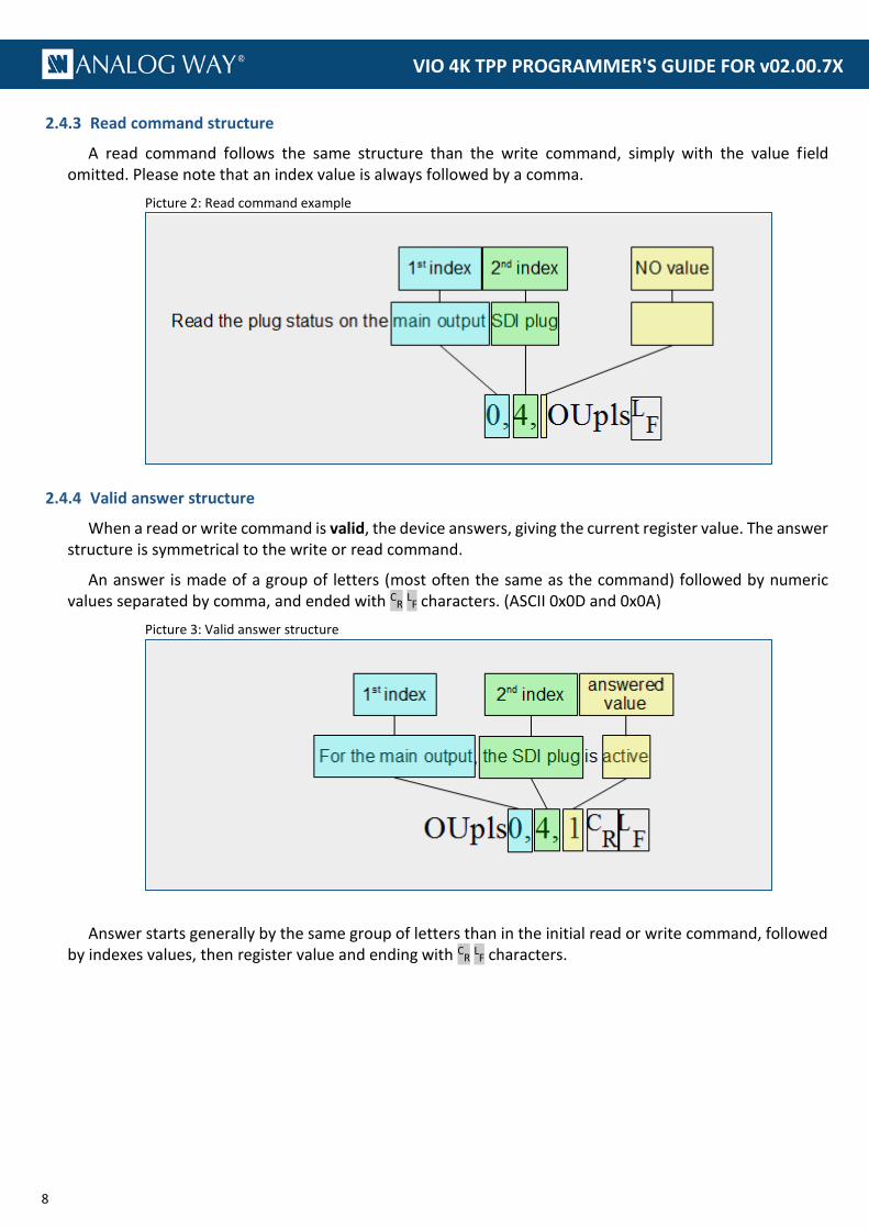
3.5.4 Example of preset recall (manual mode)
Picture 11: Example of load a preset in manual mode
In manual mode, the commutation with transition is called only when the user send the PRESET_APPLY_REQUEST.
3.6 Changing a source displayed in the layer
3.6.1 Usage
The “Layer Source change” action allows changing the source displayed in a layer of a screen. It can be used automatically and with the manual apply mode.
The PE_INPUTNUM register is used to know and change the source displayed in the layer of the preset.
Warning: In manual mode, when change request is emit, the register has a different value compared to the genuine current input.
3.6.2 Detailed commands sequence
Syntax: <source> PRinpLF
The <source> is the register value giving the source: 0 for none and from 1 up to 9 for source key.
Answer: PRinp <source>CR
LF
Example: 3PRinpLF in the layer assigns the HD15 input.
Picture 12: Changing a source - Web RCS
21
VIO 4K TPP PROGRAMMER'S GUIDE FOR v02.00.7X
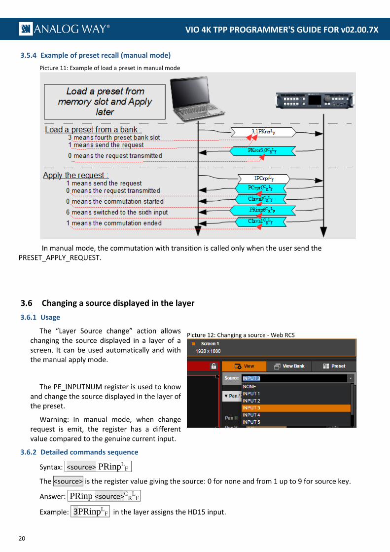
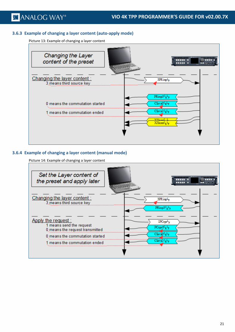
3.6.3 Example of changing a layer content (auto-apply mode)
Picture 13: Example of changing a layer content
3.6.4 Example of changing a layer content (manual mode)
Picture 14: Example of changing a layer content
22
VIO 4K TPP PROGRAMMER'S GUIDE FOR v02.00.7X
3.7 Loading a View from memory
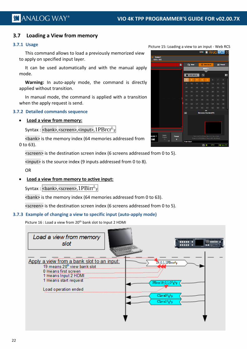
3.7.1 Usage
This command allows to load a previously memorized view to apply on specified input layer.
It can be used automatically and with the manual apply mode.
Warning: In auto-apply mode, the command is directly applied without transition.
In manual mode, the command is applied with a transition when the apply request is send.
3.7.2 Detailed commands sequence
Load a view from memory:
Syntax : <bank>,<screen>,<input>,1PBrcrLF
<bank> is the memory index (64 memories addressed from 0 to 63).
<screen> is the destination screen index (6 screens addressed from 0 to 5).
<input> is the source index (9 inputs addressed from 0 to 8).
OR
Load a view from memory to active input:
Syntax : <bank>,<screen>,1PBirrLF
<bank> is the memory index (64 memories addressed from 0 to 63).
<screen> is the destination screen index (6 screens addressed from 0 to 5).
3.7.3 Example of changing a view to specific input (auto-apply mode)
Picture 16 : Load a view from 20th bank slot to Input 2 HDMI
Picture 15: Loading a view to an input - Web RCS
23
VIO 4K TPP PROGRAMMER'S GUIDE FOR v02.00.7X
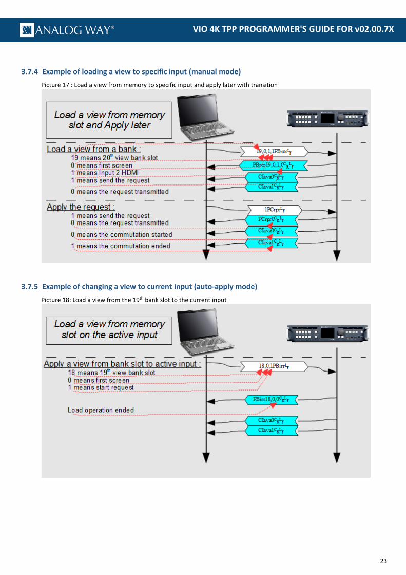
3.7.4 Example of loading a view to specific input (manual mode)
Picture 17 : Load a view from memory to specific input and apply later with transition
3.7.5 Example of changing a view to current input (auto-apply mode)
Picture 18: Load a view from the 19th bank slot to the current input

24
VIO 4K TPP PROGRAMMER'S GUIDE FOR v02.00.7X
3.7.6 Example of loading a view to current input (manual mode)
Picture 19 : Load a view from memory to the current input and apply later with transition

25
VIO 4K TPP PROGRAMMER'S GUIDE FOR v02.00.7X
3.8 Using patterns
3.8.1 Usage
To check position and colorimetry of outputs, the VIO 4K has multiples patterns. They can be applied on output format or in the area of interest. They are configurable, and most have a motion option.
3.8.2 Detailed commands sequence
For commands below, <output> is the destination output index (6 outputs addressed from 0 to 5).
Enable pattern:
Syntax : <output>,0OUpinLF
Enable by writing the value 0 and disable by writing the value 1.
Show raster box:
◦ On format: This command enables the view of edge of the output format by writing the value 1, and disables with the value 0.
Syntax : <output>,1OUpctLF
OR/AND
◦ On AIO: This command enables the view of edge of the area of interest by writing the value 1 and disables with the value 0.
Syntax : <output>,1OUactLF
Select pattern fit area: This command defines if the pattern is shown on all format area by writing the value 0 or on defined area of interest by writing the value 1.
Syntax : <output>,<value>OUfaiLF
<value> is the selected area (0 selects Format, 1 selects AOI).
Select the pattern:
Syntax : <output>,<value>OUpatLF
<value> is the pattern index (16 patterns addressed 0 for none and from 1 up to 15 for pattern keys).
Options configuration:
For all pattern, the colorimetry settings can be disabled and the pattern can move expected COLOR and CHECKERBOARD patterns.
o Disable colorimetry settings :
Syntax : <output>,<value>OUpdcLF
It is disable by writing <value> 1 and enable with 0.
o Moving option :
Syntax : <output>,<value>OUmovLF
It is enable by writing <value> 1 and disable with 0.
Picture 20: Show a pattern in an output - Web RCS

26
VIO 4K TPP PROGRAMMER'S GUIDE FOR v02.00.7X
Specifics options configuration: According to the selected pattern, options are available.
COLOR pattern: define RGB color.
GRID CUSTOM pattern: define the grid’s size, the background color, the thickness and show block ID.
CROSSHATCH pattern: define the crosshatch’s size.
CHECKERBOARD pattern: define the square’s size, start with black or white.
Options values are detailed in the “VIO4K_TPP_variables_for_v02-00-7X.xls” document.
3.9 Using snapshots
Small snapshots of live inputs and outputs, frame and logos are available. Live input and live output snapshots are regularly refreshed, while frame snapshots are refreshed only on change.
Snapshot request rate must not be more than 1 per second.
Picture maximal size is 256 pixels (width) by up to 256 pixels (height). The size depends on aspect ratio.
Live output snapshot maximum size is 512 pixels (width) by up to 512 pixels (height).
Picture type is PNG.
Live inputs snapshot URL are:
o http://<machine_ip>/LIVE_SNAPSHOT/SNAP_INPUT_1.png
up to
o http://<machine_ip>/LIVE_SNAPSHOT/SNAP_INPUT_OPT_2.png
Live outputs snapshot URL are:
o http://<machine_ip>/LIVE_SNAPSHOT/SNAP_OUTPUT_MAIN.png
up to
o http://<machine_ip>/LIVE_SNAPSHOT/SNAP_INPUT_OPT_2.png
Frames snapshot URL are:
o http://<machine ip>/FRAMELIB_THUMBNAIL/STILL_LIBRARY_1.png
up to
o http://<machine ip>/ FRAMELIB_THUMBNAIL/STILL_LIBRARY_50.png

27
VIO 4K TPP PROGRAMMER'S GUIDE FOR v02.00.7X
4 NOTES
4.1 Using this document
This document contains many internal links. You can improve your navigation by using the “previous page” function, as in the following example:
Picture 21: PDF reader, Previous and Next page buttons

28
VIO 4K TPP PROGRAMMER'S GUIDE FOR v02.00.7X
V1.00 – Apr/03/2017