Embed Size (px)
Citation preview
7/30/2019 vila load
http://slidepdf.com/reader/full/vila-load 1/46
Guide to Heating
and Cooling Load
Calculations in High
Performance Homes
March 2011
Prepared by:
Arlan Burdick
© IBACOS, Inc. 2011
The information contained within this report is the property of IBACOS ®
and Building America may not be reproduced or used without written
permission.
2214 Liberty Avenue
Pittsburgh, PA 15222
www.ibacos.com
1-800-611-7052
7/30/2019 vila load
http://slidepdf.com/reader/full/vila-load 2/46
Guide to Heating and Cooling Load Calculations in High Performance HomesMarch 2011
2
Forward
The Strategy Guideline to Accurate Heating and Cooling Load Calculations provides information to the followinggroups:
• Heating Ventilation and Air Conditioning (HVAC) Mechanical Contractors
• HVAC System Designers
• Builders
• House Remodelers
This guide can be used as a point of entry for collaborative discussions between a builder, HVAC contractor, and
other trade partners to understand the importance of appropriately calculate peak heating and cooling loads, as
the first step of HVAC system design.
Accurate load calculations have a direct impact on energy efficiency, occupant comfort, indoor air quality, andbuilding durability. The load calculation is the first step of the iterative HVAC design procedure, as a full HVAC
design involves much more than just the load calculation. The loads modeled by the heating and cooling load
calculation process will dictate the equipment selection and duct design to deliver conditioned air to the rooms of
the house. This guide references the methodologies of the Air Conditioning Contractors of America (ACCA)
publication Manual J Residential Load Calculation Eighth Edition (ACCA MJ8), which in turn references
information provided by the American Society of Heating, Refrigerating and Air-Conditioning Engineers
(ASHRAE). ACCA MJ8 only applies to single family detached dwellings, low-rise condominiums, and townhouses
This guide is not a new method for performing load calculations, a substitute for established methods of
performing load calculations, or step-by-step instructions on how to perform the load calculations. This guide
presents the key criteria required to create accurate heating and cooling load calculations and offers examples ofthe implications when inaccurate adjustments are applied to the HVAC design process. The guide shows, through
realistic examples, how various defaults and arbitrary safety factors can lead to significant increases in the load
estimate. Emphasis is placed on the risks incurred from inaccurate adjustments or ignoring critical inputs of the
load calculation.
7/30/2019 vila load
http://slidepdf.com/reader/full/vila-load 3/46
Guide to Heating and Cooling Load Calculations in High Performance HomesMarch 2011
3
Table of Contents
Definitions...................................................................................................................................................... 4
Executive Summary ...................................................................................................................................... 5
Introduction ................................................................................................................................................... 8
Baseline Load Calculation........................................................................................................................... 11
Load Components ....................................................................................................................................... 13
Peak Heating Load .................................................................................................................................. 14
Peak Cooling Load .................................................................................................................................. 16
Location – Design Conditions ................................................................................................................. 17
Orientation ............................................................................................................................................... 20
Building Components .............................................................................................................................. 23
Heating and Cooling System Location and Duct Leakage ..................................................................... 23
Ventilation/Infiltration ............................................................................................................................... 24
Risks Associated with Over-sizing .............................................................................................................. 24
First Cost, Energy Costs and Durability .................................................................................................. 24
Comfort - Space Temperatures ............................................................................................................... 24
Comfort - Humidity Control ...................................................................................................................... 24
Load Dependencies .................................................................................................................................... 25
Outdoor/Indoor Design Condition Dependencies ................................................................................... 25
Ductwork Conditions Dependencies ....................................................................................................... 31
Ventilation/Infiltration Conditions Dependencies ..................................................................................... 33
Combined Dependencies ........................................................................................................................ 36
Conclusion .................................................................................................................................................. 38
References .............................................................................................................................................. 40
Appendix A: Enhancements to Scope for Mechanical Contractor/HVAC Manual J Designer .................... 42
Appendix B: ACCA Manual J8 Input Checklist ........................................................................................... 43
7/30/2019 vila load
http://slidepdf.com/reader/full/vila-load 4/46
Guide to Heating and Cooling Load Calculations in High Performance HomesMarch 2011
4
Definitions
ACCA Air Conditioning Contractors of America
ACCA MJ8 Air Conditioning Contractors of America publication Manual J Residential Load
Calculation Eighth Edition
ACH50 Air Changes per Hour at 50 Pascals
ACHn Air Changes per Hour Natural
AED Adequate Exposure Diversity
ALP Average Load Procedure
ASHRAE American Society of Heating, Refrigeration and Air-Conditioning Engineers
Btu British Thermal Unit
Btu/h Btu per hour
cfm Cubic Feet per Minute
°Fdb Degree Fahrenheit Dry Bulb
°Fwb Degree Fahrenheit Wet Bulb
HVAC Heating, Ventilation and Air Conditioning
PLP Peak Load Procedure
RESNET Residential Energy Services Network
RH Relative Humidity
SHGC Solar Heat Gain Coefficient
7/30/2019 vila load
http://slidepdf.com/reader/full/vila-load 5/46
Guide to Heating and Cooling Load Calculations in High Performance HomesMarch 2011
5
Executive Summary
The heating and cooling load calculation is the first step of the iterative HVAC design procedure, a full HVAC
design involves more than the just the load estimate calculation. Right-sizing the HVAC system, selecting HVAC
equipment and designing the air distribution system to meet the accurate predicted heating and cooling loads,
begins with an accurate understanding of the heating and cooling loads on a space. The Air Conditioning
Contractors of America (ACCA) Manual J Version 8 provides the detailed steps required to calculate the heating
and cooling loads. The accurate heating and cooling loads are used to right-size the equipment with ACCA
Manual S Residential Equipment Selection , then to design the air distribution system and ductwork with ACCA
Manual T Air Distribution Basics for Residential and Small Commercial Buildings and ACCA Manual D Residentia
Duct System Procedure .
In the author’s experience several factors have lead to a general industry resistance to initially perform an
accurate load calculation, which is necessary for the design of a right-sized HVAC system. Historically, energycodes did not address stringent levels of energy efficiency, and rules of thumb were developed for HVAC sizing
that worked based on the construction at that time. Building enclosures have become more energy efficient as
energy codes have become more stringent since 2000; however, these rules of thumb have not changed. Full
credit should be taken for improvements such as better windows, enhanced air tightness strategies, and
additional insulation.
ACCA MJ8 says of safety factors:
"Manual J calculations should be aggressive, which means that the designer should take full advantage of
legitimate opportunities to minimize the size of estimated loads. In this regard, the practice of
manipulating the outdoor design temperature, not taking full credit for efficient construction features,ignoring internal and external window shading devices and then applying an arbitrary "safety factor" is
indefensible.”
“No additional safety factors are required when load estimates are based on accurate information
pertaining to the envelope construction and duct system efficiency. Large errors are possible if there is
uncertainty about insulation levels, fenestration performance, envelope tightness or the efficiency of the
duct runs installed in the unconditioned space.”
7/30/2019 vila load
http://slidepdf.com/reader/full/vila-load 6/46
Guide to Heating and Cooling Load Calculations in High Performance HomesMarch 2011
6
Examples in this guide show the implications when inaccurate adjustments are applied to the heating and cooling
load calculation process. In order to demonstrate the impact on the loads when common “safety factors” are
applied to the load calculation process two houses that meet the 2009 International Energy Conservation Code® (IECC) prescriptive path were modeled as the accurate baseline. One house was modeled in Chicago, IL and one
in Orlando, FL. Several common “safety factors” were applied to the baseline models to create examples of how
and where load calculations can be inflated leading to system over-sizing. The baseline load calculations were
manipulated for:
• Outdoor/Indoor Design Conditions
• Building Components
• Ductwork Conditions
• Ventilation/Infiltration Conditions
• Worst Case Scenario (combining all the safety factors)
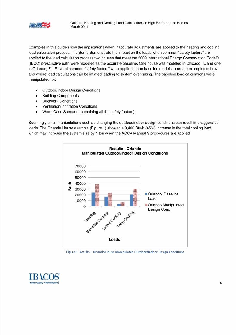
Seemingly small manipulations such as changing the outdoor/indoor design conditions can result in exaggerated
loads. The Orlando House example (Figure 1) showed a 9,400 Btu/h (45%) increase in the total cooling load,
which may increase the system size by 1 ton when the ACCA Manual S procedures are applied.
Figure 1. Results – Orlando House Manipulated Outdoor/Indoor Design Conditions
0
10000
20000
30000
40000
50000
60000
70000
B t u h
Loads
Results - OrlandoManipulated Outdoor/Indoor Design Conditions
Orlando BaselineLoad
Orlando ManipulatedDesign Cond
7/30/2019 vila load
http://slidepdf.com/reader/full/vila-load 7/46
Guide to Heating and Cooling Load Calculations in High Performance HomesMarch 2011
7
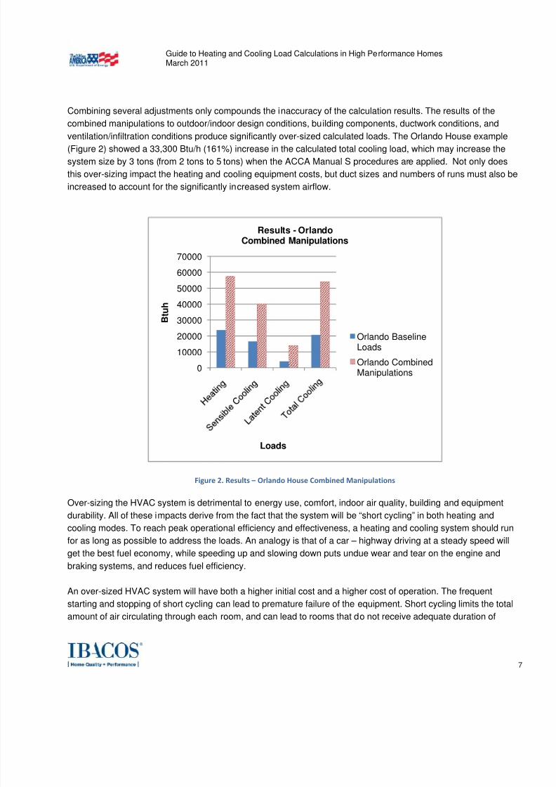
Combining several adjustments only compounds the inaccuracy of the calculation results. The results of the
combined manipulations to outdoor/indoor design conditions, building components, ductwork conditions, and
ventilation/infiltration conditions produce significantly over-sized calculated loads. The Orlando House example(Figure 2) showed a 33,300 Btu/h (161%) increase in the calculated total cooling load, which may increase the
system size by 3 tons (from 2 tons to 5 tons) when the ACCA Manual S procedures are applied. Not only does
this over-sizing impact the heating and cooling equipment costs, but duct sizes and numbers of runs must also be
increased to account for the significantly increased system airflow.
Figure 2. Results – Orlando House Combined Manipulations
Over-sizing the HVAC system is detrimental to energy use, comfort, indoor air quality, building and equipment
durability. All of these impacts derive from the fact that the system will be “short cycling” in both heating and
cooling modes. To reach peak operational efficiency and effectiveness, a heating and cooling system should run
for as long as possible to address the loads. An analogy is that of a car – highway driving at a steady speed will
get the best fuel economy, while speeding up and slowing down puts undue wear and tear on the engine andbraking systems, and reduces fuel efficiency.
An over-sized HVAC system will have both a higher initial cost and a higher cost of operation. The frequent
starting and stopping of short cycling can lead to premature failure of the equipment. Short cycling limits the total
amount of air circulating through each room, and can lead to rooms that do not receive adequate duration of
0
10000
20000
30000
40000
5000060000
70000
B t u h
Loads
Results - OrlandoCombined Manipulations
Orlando BaselineLoads
Orlando CombinedManipulations
7/30/2019 vila load
http://slidepdf.com/reader/full/vila-load 8/46
Guide to Heating and Cooling Load Calculations in High Performance HomesMarch 2011
8
airflow. In the cooling season in humid climates, cold clammy conditions can occur due to reduced
dehumidification caused by the short cycling of the equipment. The system must run long enough for the coil to
reach the temperature for condensation to occur and an over-sized system that short cycles may not run longenough to sufficiently condense moisture from the air. Excess humidity in the conditioned air delivered to a space
may lead to mold growth within the house.
Introduction
Heating and cooling loads are the measure of energy needed to be added or removed from a space by the HVAC
system to provide the desired level of comfort within a space. Right-sizing the HVAC system begins with an
accurate understanding of the heating and cooling loads on a space. Right-sizing is selecting HVAC equipment
and designing the air distribution system to meet the accurate predicted heating and cooling loads of the house.
The values determined by the heating and cooling load calculation process will dictate the equipment selection
and duct design to deliver conditioned air to the rooms of the house, right-sizing the HVAC system. The heatingand cooling load calculation results will have a direct impact on first construction costs along with the operating
energy efficiency, occupant comfort, indoor air quality, and building durability.
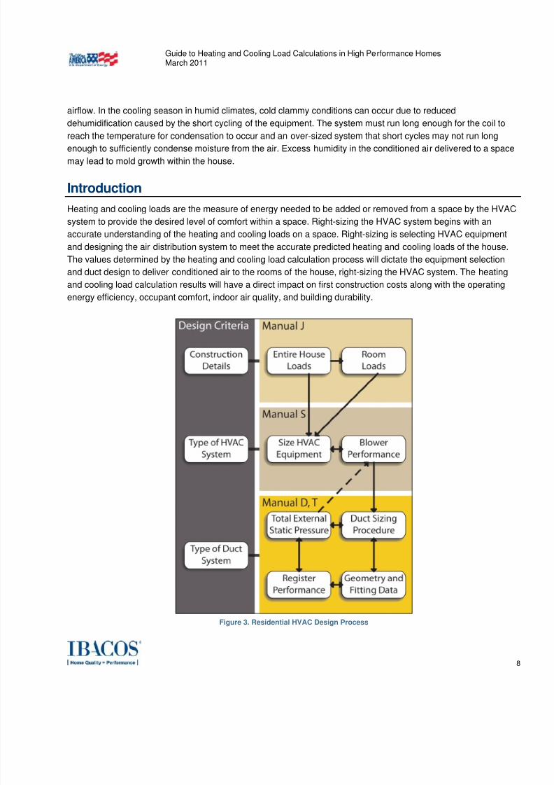
Figure 3. Residential HVAC Design Process
7/30/2019 vila load
http://slidepdf.com/reader/full/vila-load 9/46
Guide to Heating and Cooling Load Calculations in High Performance HomesMarch 2011
9
A full HVAC design involves more than the just the load estimate calculation, the load calculation is the first step
of the iterative HVAC design procedure (Figure 3). The values calculated from the ACCA MJ8 procedures are
then used to select the size of the mechanical equipment. Mechanical equipment selection is done with the aid ofthe ACCA Manual S Residential Equipment Selection . The conditioned air delivery to the space is controlled by
the type and size of the air outlet. ACCA Manual T Air Distribution Basics for Residential and Small Commercial
Buildings provides the guidance on selecting the air outlet size and type. The ductwork that carries the
conditioned air to meet the load requirements of the space from the mechanical equipment to the air outlet is
sized with the aid of the ACCA Manual D Residential Duct System Procedure . The iterative nature of the process
involves balancing the blower performance of the mechanical equipment against the pressure losses of the
ductwork and air outlets to deliver the conditioned air to the space in as unobtrusive manner as possible. The
ACCA procedures have been written into commercial software packages to help the designer work through the
many iterations required for a good design.
For the purposes of this guide, an energy efficient house is defined as one that is designed and built fordecreased energy use and improved occupant comfort through higher levels of insulation, more energy efficient
windows, high efficiency space conditioning and water heating equipment, energy efficient lighting and
appliances, reduced air infiltration, and controlled mechanical ventilation. Specification levels for energy efficient
houses have historically been prescribed by beyond code programs that set a percentage better than code for
energy use, such as ENERGY STAR® that requires houses to be 15% more energy efficient than code. Beyond
code programs continue to set a percentage better than the improved codes for energy use, raising the bar for
whole house energy efficiency. The 2009 International Energy Conservation Code® (IECC) establishes an
estimated 15% improvement in energy efficiency over the previous 2006 IECC requirements. Ongoing code
cycles are anticipated to incrementally further increase the minimum efficiency of a house. For example, the 2012
IECC achieves approximately 30% savings over the 2006 version. As the new codes are adopted and
implemented, a house that was built under an above code program in 2010 will likely be the code mandatedhouse in 2015. As the energy efficiency of the house is increased under code or above code programs, the peak
heating and cooling loads are significantly reduced.
ACCA MJ8 says of safety factors:
"Manual J calculations should be aggressive, which means that the designer should take full advantage of
legitimate opportunities to minimize the size of estimated loads. In this regard, the practice of
manipulating the outdoor design temperature, not taking full credit for efficient construction features,
ignoring internal and external window shading devices and then applying an arbitrary "safety factor" is
indefensible.”
An accurate evaluation of the heating and cooling loads requires a complete understanding and accounting of the
building components that make up the thermal enclosure along with the outdoor/indoor contributions to the load.
The load calculation for a house where the building enclosure has been enhanced with added air tightness
strategies, better windows, and additional insulation will be more sensitive to manipulation of the inputs. In the
authors experience several factors have lead to a general industry resistance to initially perform an accurate load
7/30/2019 vila load
http://slidepdf.com/reader/full/vila-load 10/46
Guide to Heating and Cooling Load Calculations in High Performance HomesMarch 2011
10
calculation, which is necessary for the design of a right-sized HVAC system. Historically, energy codes did not
address stringent levels of energy efficiency, and rules of thumb were developed for HVAC sizing that worked
based on the construction at that time. Building enclosures have become more and more energy efficient asenergy codes have become more stringent since 2000, but these rules of thumb have not changed. Full credit
should be taken by the HVAC system designer for improvements such as better windows, enhanced air tightness
strategies, and additional insulation.
HVAC contractors are also not 100% convinced that the builder is managing all other trades to construct a
thermal enclosure that truly achieves targeted performance levels. Typically the HVAC installer will get the
comfort complaint if the building enclosure has not met the builder’s stated specifications, even though the HVAC
system is designed and installed according to the stated specifications. Many HVAC companies rely on the “400
square feet per ton” rule for sizing systems. Even when a load calculation is required to be performed, the
contractor may often manipulate the inputs to get a result that is close to the “400 square foot” rule of thumb.
Overcoming this bias requires the builder and their trade base sharing an understanding of the importance ofachieving the stated building enclosure specifications, and undertaking visual inspections and testing during
construction to verify the building meets the intended level of performance. When these checks and balances are
in place, the perceived need to add factors of safety during the heating and cooling load calculation process can
be avoided. Appendix A contains suggested enhancements to the scope of work for the Mechanical Contractor or
HVAC designer.
The critical inputs and their associated risks discussed in this guide are:
• Design Conditions
o Location
o Latitude
o Elevation
o Outdoor temperature and relative humidity
• Orientation
• Internal conditions
o Indoor temperature and relative humidity
• Building Enclosure
o Insulation levels of walls, ceilings, and floors
o Window specification
o Thermal conductivity
o Solar Heat Gain Coefficient (SHGC)
o Infiltration and ventilation levels
o Interior and exterior shading
• Internal loads
7/30/2019 vila load
http://slidepdf.com/reader/full/vila-load 11/46
Guide to Heating and Cooling Load Calculations in High Performance HomesMarch 2011
11
o Number of occupants
o Electronics, lighting and appliances
A concise checklist to aide in compiling the information required to accurately calculate loads is located in
Appendix B of this document.
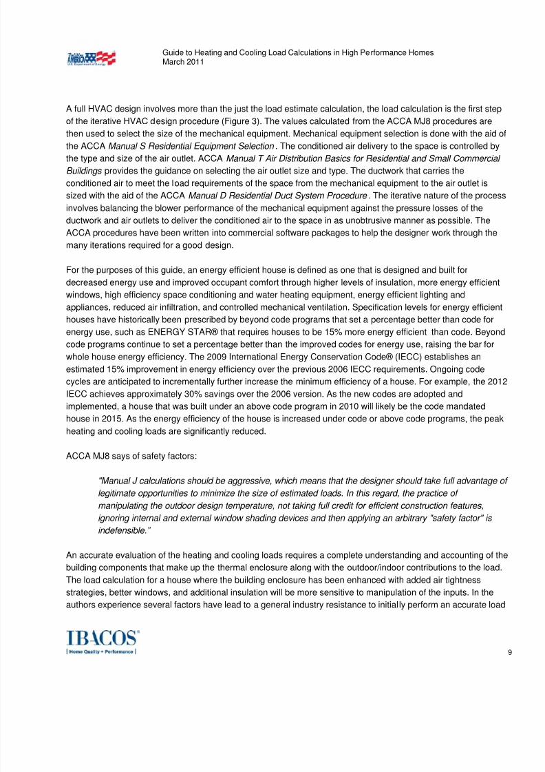
Baseline Load Calculation
In order to demonstrate the impact on the loads when common inaccurate adjustments (also known in
the industry as “safety factors”) are made to the house, ACCA MJ8 load calculations were performed on
two houses (Figure 4) that meet the 2009 International Energy Conservation Code® (IECC) prescriptivepath. The first (“Chicago House”) is a one story 2,223 ft2 (above grade) house with a full conditioned
basement in Chicago, IL (IECC Climate Zone 5 - CZ5). The other (“Orlando House”) is a 2,223 ft2 one
story slab-on-grade house in Orlando, FL (IECC Climate Zone 2 - CZ2). The input conditions used tomodel the two houses are listed in Table 1.
Figure 4. Typical 2223 ft2
One Story House
7/30/2019 vila load
http://slidepdf.com/reader/full/vila-load 12/46
Guide to Heating and Cooling Load Calculations in High Performance HomesMarch 2011
12
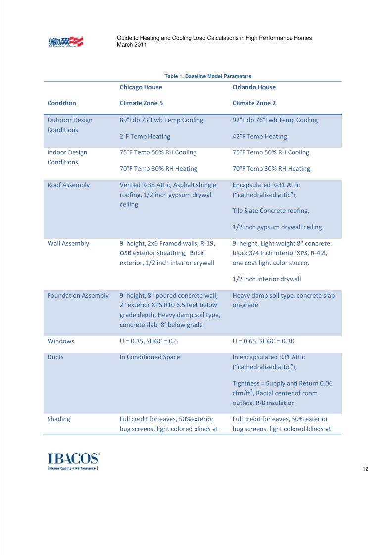
Table 1. Baseline Model Parameters
Condition Chicago House Climate Zone 5
Orlando House Climate Zone 2
Outdoor Design
Conditions
89°Fdb 73°Fwb Temp Cooling
2°F Temp Heating
92°F db 76°Fwb Temp Cooling
42°F Temp Heating
Indoor Design
Conditions
75°F Temp 50% RH Cooling
70°F Temp 30% RH Heating
75°F Temp 50% RH Cooling
70°F Temp 30% RH Heating
Roof Assembly Vented R‐38 Attic, Asphalt shingle
roofing, 1/2
inch
gypsum
drywall
ceiling
Encapsulated R‐31 Attic
(“cathedralized attic”),
Tile Slate Concrete roofing,
1/2 inch gypsum drywall ceiling
Wall Assembly 9' height, 2x6 Framed walls, R‐19,
OSB exterior sheathing, Brick
exterior, 1/2 inch interior drywall
9' height, Light weight 8" concrete
block 3/4 inch interior XPS, R‐4.8,
one coat light color stucco,
1/2 inch interior drywall
Foundation Assembly
9'
height,
8"
poured
concrete
wall,
2" exterior XPS R10 6.5 feet below
grade depth, Heavy damp soil type,
concrete slab 8’ below grade
Heavy damp
soil
type,
concrete
slab
‐
on‐grade
Windows U = 0.35, SHGC = 0.5 U = 0.65, SHGC = 0.30
Ducts In Conditioned Space In encapsulated R31 Attic
(“cathedralized attic”),
Tightness = Supply and Return 0.06
cfm/ft2, Radial center of room
outlets, R‐8 insulation
Shading Full credit for eaves, 50%exterior
bug screens, light colored blinds at
Full credit for eaves, 50% exterior
bug screens, light colored blinds at
7/30/2019 vila load
http://slidepdf.com/reader/full/vila-load 13/46
Guide to Heating and Cooling Load Calculations in High Performance HomesMarch 2011
13
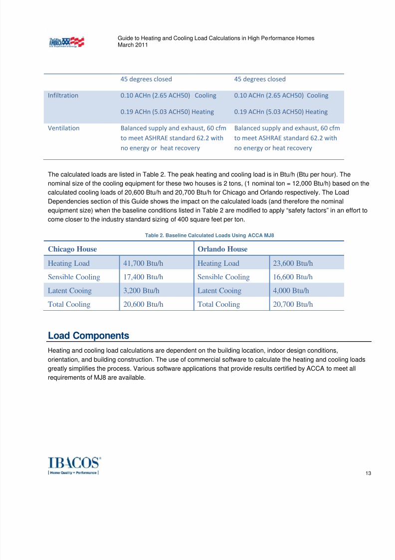
45 degrees closed 45 degrees closed
Infiltration
0.10
ACHn
(2.65
ACH50)
Cooling
0.19 ACHn (5.03 ACH50) Heating
0.10
ACHn
(2.65
ACH50)
Cooling
0.19 ACHn (5.03 ACH50) Heating
Ventilation Balanced supply and exhaust, 60 cfm
to meet ASHRAE standard 62.2 with
no energy or heat recovery
Balanced supply and exhaust, 60 cfm
to meet ASHRAE standard 62.2 with
no energy or heat recovery
The calculated loads are listed in Table 2. The peak heating and cooling load is in Btu/h (Btu per hour). The
nominal size of the cooling equipment for these two houses is 2 tons, (1 nominal ton = 12,000 Btu/h) based on the
calculated cooling loads of 20,600 Btu/h and 20,700 Btu/h for Chicago and Orlando respectively. The Load
Dependencies section of this Guide shows the impact on the calculated loads (and therefore the nominal
equipment size) when the baseline conditions listed in Table 2 are modified to apply “safety factors” in an effort to
come closer to the industry standard sizing of 400 square feet per ton.
Table 2. Baseline Calculated Loads Using ACCA MJ8
Chicago House Orlando House
Heating Load 41,700 Btu/h Heating Load 23,600 Btu/h
Sensible Cooling 17,400 Btu/h Sensible Cooling 16,600 Btu/h
Latent Cooing 3,200 Btu/h Latent Cooing 4,000 Btu/hTotal Cooling 20,600 Btu/h Total Cooling 20,700 Btu/h
Load Components
Heating and cooling load calculations are dependent on the building location, indoor design conditions,
orientation, and building construction. The use of commercial software to calculate the heating and cooling loads
greatly simplifies the process. Various software applications that provide results certified by ACCA to meet all
requirements of MJ8 are available.

7/30/2019 vila load
http://slidepdf.com/reader/full/vila-load 14/46
Guide to Heating and Cooling Load Calculations in High Performance HomesMarch 2011
14
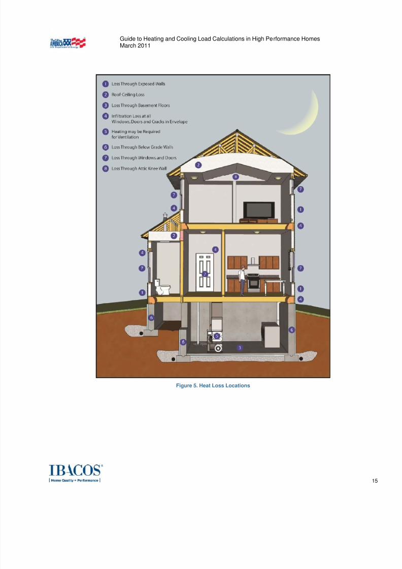
Peak Heating Load
The peak heating load represents the amount of heat lost to the outdoor environment at design outdoor and
indoor conditions, which must be made up by the HVAC system to maintain occupant comfort (Figure 5). There isone relatively straightforward and uncomplicated heat loss calculation procedure used in ACCA MJ8. The
components of the heating load calculation are covered in depth in Section 4 of the ACCA MJ8. The total
estimated heat loss is a combination of the sensible heat loss through conduction, infiltration, and ventilation
loads. No credit is taken for solar gains or internal loads in calculating the heating load because the peak heat
loss occurs at night during periods of occupant inactivity.
7/30/2019 vila load
http://slidepdf.com/reader/full/vila-load 15/46
Guide to Heating and Cooling Load Calculations in High Performance HomesMarch 2011
15
Figure 5. Heat Loss Locations
7/30/2019 vila load
http://slidepdf.com/reader/full/vila-load 16/46
Guide to Heating and Cooling Load Calculations in High Performance HomesMarch 2011
16
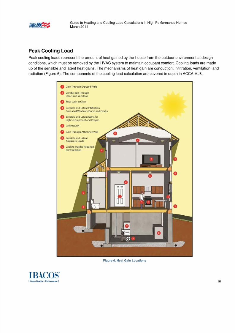
Peak Cooling Load
Peak cooling loads represent the amount of heat gained by the house from the outdoor environment at designconditions, which must be removed by the HVAC system to maintain occupant comfort. Cooling loads are made
up of the sensible and latent heat gains. The mechanisms of heat gain are conduction, infiltration, ventilation, and
radiation (Figure 6). The components of the cooling load calculation are covered in depth in ACCA MJ8.
Figure 6. Heat Gain Locations
7/30/2019 vila load
http://slidepdf.com/reader/full/vila-load 17/46
Guide to Heating and Cooling Load Calculations in High Performance HomesMarch 2011
17
The cooling load calculation procedure in ACCA MJ8 is more complex than the heating load calculation
procedure. ACCA MJ8 documents two cooling load calculation procedures in Section 5-1, the Average Load
Procedure (ALP) and the Peak Load Procedure (PLP).
The ALP uses the conditions that are encountered in late afternoon during midsummer when solar gains and
temperatures are expected to be highest. This is a simplified method to create dependable cooling load estimates
for conventional single family detached houses with a central single zoned comfort system with Adequate
Exposure Diversity (AED). See the Orientation section of this Guide for a description of the Test for Adequate
Exposure Diversity . The ALP procedure minimizes the complexity of the calculations, however, it must be noted
the values are averaged for room-to-room loads and approximate the peak block load for the structure.
The PLP looks at time of day sensitivities for midsummer conditions, recognizing that in some designs certain
rooms may have significant solar gains during midday or the morning. An example might be a highly glazed
sunroom on the south face of a house with considerable east, west and south glass, or a living room with lots ofsouth facing glass and a moderate amount of west glass. The PLP is the residential equivalent to a commercial
cooling load procedure, and should be used when a house does not have AED. It is used to estimate peak room
loads for the midsummer season and the hour of day in which that room has its maximum solar gain. The whole
house cooling load is the sum of the peak for each room.
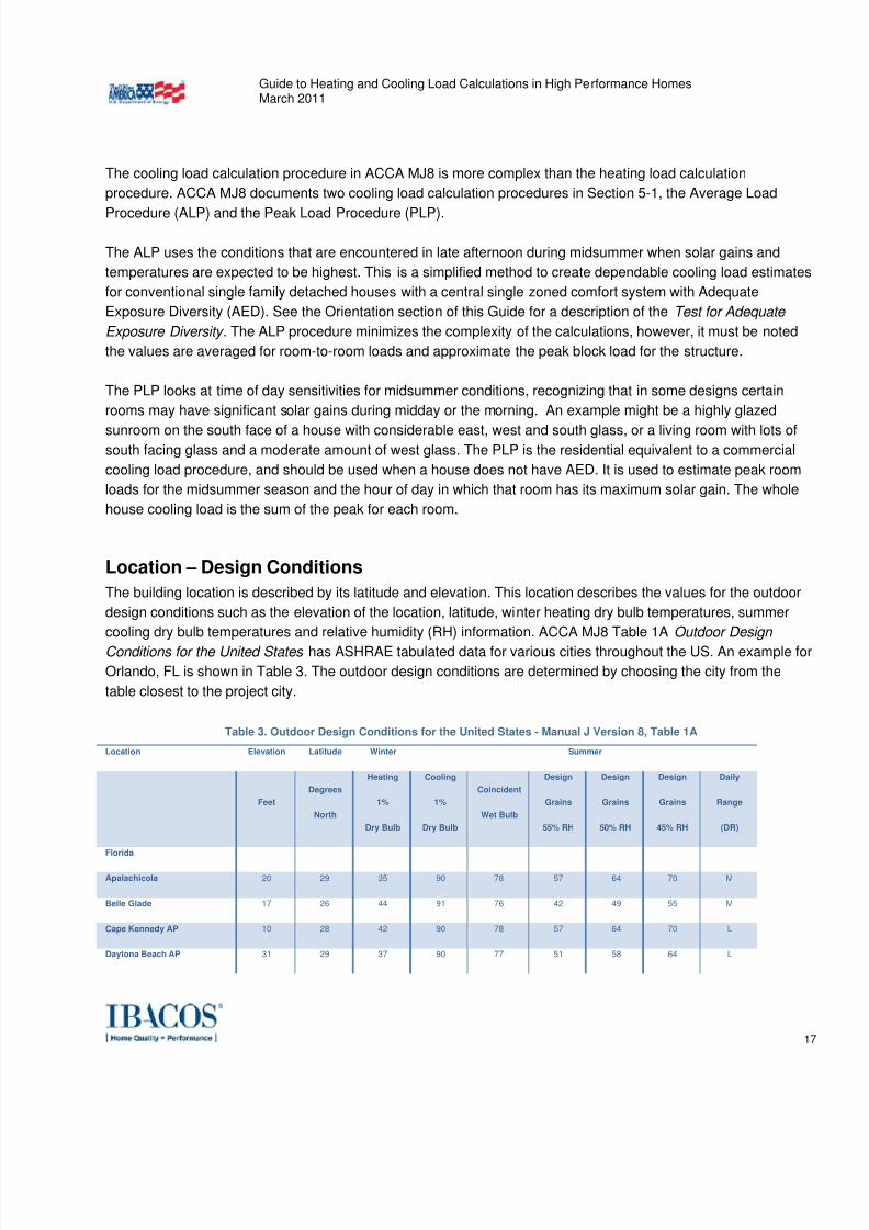
Location – Design Conditions
The building location is described by its latitude and elevation. This location describes the values for the outdoor
design conditions such as the elevation of the location, latitude, winter heating dry bulb temperatures, summer
cooling dry bulb temperatures and relative humidity (RH) information. ACCA MJ8 Table 1A Outdoor Design
Conditions for the United States has ASHRAE tabulated data for various cities throughout the US. An example for
Orlando, FL is shown in Table 3. The outdoor design conditions are determined by choosing the city from the
table closest to the project city.
Table 3. Outdoor Design Conditions for the United States - Manual J Version 8, Table 1A
Location Elevation Latitude Winter Summer
Feet
Degrees
North
Heating
1%
Dry Bulb
Cooling
1%
Dry Bulb
Coincident
Wet Bulb
Design
Grains
55% RH
Design
Grains
50% RH
Design
Grains
45% RH
Daily
Range
(DR)
Florida
Apalachicola 20 29 35 90 78 57 64 70 M
Belle Glade 17 26 44 91 76 42 49 55 M
Cape Kennedy AP 10 28 42 90 78 57 64 70 L
Daytona Beach AP 31 29 37 90 77 51 58 64 L
7/30/2019 vila load
http://slidepdf.com/reader/full/vila-load 18/46
Guide to Heating and Cooling Load Calculations in High Performance HomesMarch 2011
18
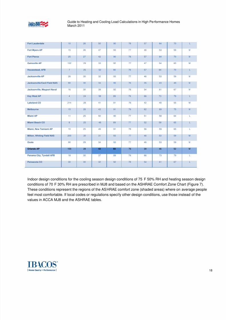
Fort Lauderdale 10 26 50 90 78 57 64 70 L
Fort Myers AP 15 26 47 93 77 46 53 59 M
Fort Pierce 25 27 42 90 78 57 64 70 M
Gainsville AP 152 29 33 92 77 47 54 60 M
Housestead, AFB 7 25 52 90 76 57 64 70 L
Jacksonville AP 26 30 32 93 77 46 53 59 M
Jacksonville/Cecil Field NAS 80 30 34 95 76 35 43 49 M
Jacksonville, Mayport Naval 16 30 39 92 78 54 61 67 M
Key West AP 4 24 58 89 79 66 73 79 L
Lakeland CO 214 28 41 91 76 42 49 55 M
Melbourne 15 28 43 91 79 62 69 75 M
Miami AP 11 25 50 90 77 51 58 64 L
Miami Beach CO 8 25 48 89 77 52 59 65 L
Miami, New Tamiami AP 10 25 49 91 78 56 59 65 L
Milton, Whiting Field NAS 200 30 31 93 77 46 53 59 M
Ocala 90 29 34 93 77 46 53 59 M
Orlando AP 100 28 42 93 76 39 46 52 M
Panama City, Tyndall AFB 18 30 37 89 79 66 73 79 L
Pensacola CO 30 30 32 92 78 54 61 67 L
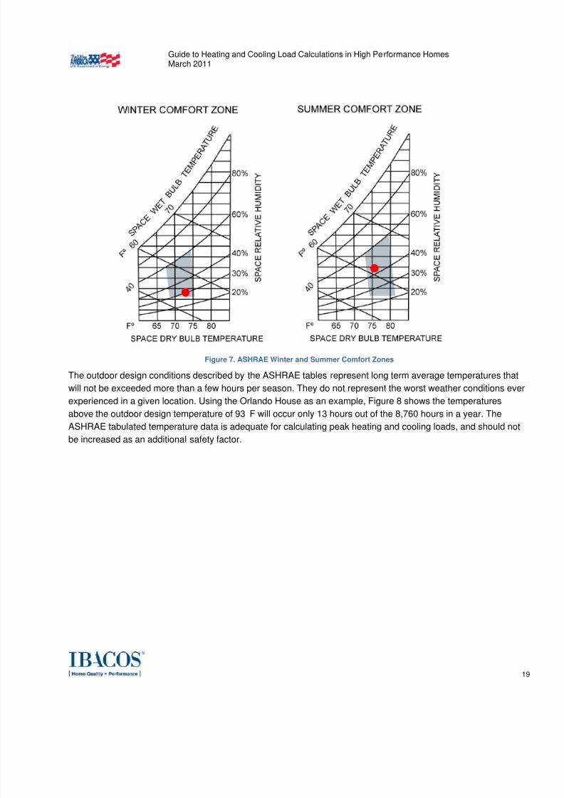
Indoor design conditions for the cooling season design conditions of 75˚F 50% RH and heating season design
conditions of 70˚F 30% RH are prescribed in MJ8 and based on the ASHRAE Comfort Zone Chart (Figure 7).
These conditions represent the regions of the ASHRAE comfort zone (shaded areas) where on average people
feel most comfortable. If local codes or regulations specify other design conditions, use those instead of the
values in ACCA MJ8 and the ASHRAE tables.
7/30/2019 vila load
http://slidepdf.com/reader/full/vila-load 19/46
Guide to Heating and Cooling Load Calculations in High Performance HomesMarch 2011
19
Figure 7. ASHRAE Winter and Summer Comfort Zones
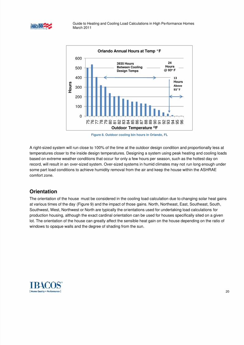
The outdoor design conditions described by the ASHRAE tables represent long term average temperatures that
will not be exceeded more than a few hours per season. They do not represent the worst weather conditions ever
experienced in a given location. Using the Orlando House as an example, Figure 8 shows the temperatures
above the outdoor design temperature of 93˚F will occur only 13 hours out of the 8,760 hours in a year. The
ASHRAE tabulated temperature data is adequate for calculating peak heating and cooling loads, and should not
be increased as an additional safety factor.
7/30/2019 vila load
http://slidepdf.com/reader/full/vila-load 20/46
Guide to Heating and Cooling Load Calculations in High Performance HomesMarch 2011
20
Figure 8. Outdoor cooling bin hours in Orlando, FL
A right-sized system will run close to 100% of the time at the outdoor design condition and proportionally less at
temperatures closer to the inside design temperatures. Designing a system using peak heating and cooling loads
based on extreme weather conditions that occur for only a few hours per season, such as the hottest day on
record, will result in an over-sized system. Over-sized systems in humid climates may not run long enough under
some part load conditions to achieve humidity removal from the air and keep the house within the ASHRAE
comfort zone.
Orientation
The orientation of the house must be considered in the cooling load calculation due to changing solar heat gains
at various times of the day (Figure 9) and the impact of those gains. North, Northeast, East, Southeast, South,
Southwest, West, Northwest or North are typically the orientations used for undertaking load calculations for
production housing, although the exact cardinal orientation can be used for houses specifically sited on a given
lot. The orientation of the house can greatly affect the sensible heat gain on the house depending on the ratio of
windows to opaque walls and the degree of shading from the sun.
0
100
200
300
400
500
600
7 5
7 6
7 7
7 8
7 9
8 0
8 1
8 2
8 3
8 4
8 5
8 6
8 7
8 8
8 9
9 0
9 1
9 2
9 3
9 4
9 5
9 6
H o u r s
Outdoor Temperature OF
Orlando Annual Hours at Temp °F
24Hours
@ 93o F
13 Hours
Above 93°F
3935 HoursBetween CoolingDesign Temps
7/30/2019 vila load
http://slidepdf.com/reader/full/vila-load 21/46
Guide to Heating and Cooling Load Calculations in High Performance HomesMarch 2011
21
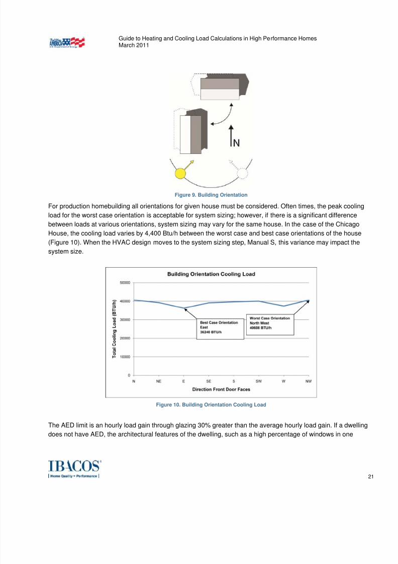
Figure 9. Building Orientation
For production homebuilding all orientations for given house must be considered. Often times, the peak cooling
load for the worst case orientation is acceptable for system sizing; however, if there is a significant difference
between loads at various orientations, system sizing may vary for the same house. In the case of the Chicago
House, the cooling load varies by 4,400 Btu/h between the worst case and best case orientations of the house
(Figure 10). When the HVAC design moves to the system sizing step, Manual S, this variance may impact the
system size.
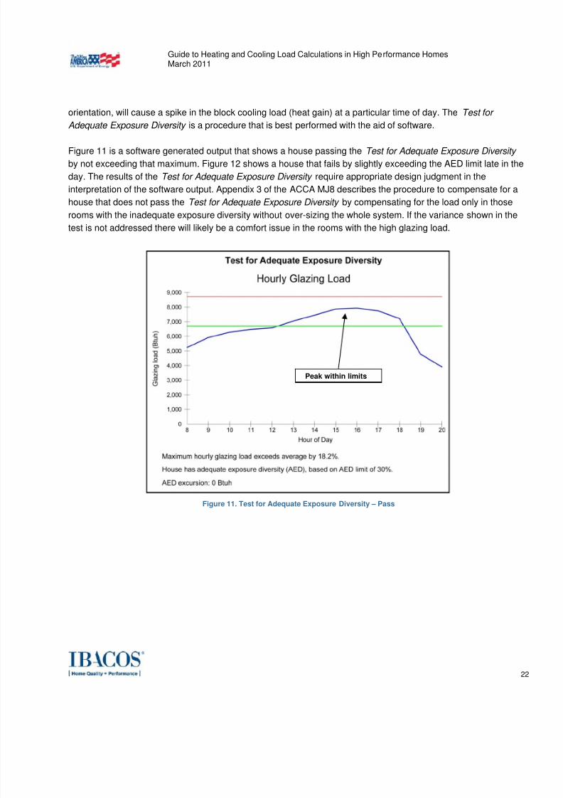
Figure 10. Building Orientation Cooling Load
The AED limit is an hourly load gain through glazing 30% greater than the average hourly load gain. If a dwelling
does not have AED, the architectural features of the dwelling, such as a high percentage of windows in one
7/30/2019 vila load
http://slidepdf.com/reader/full/vila-load 22/46
Guide to Heating and Cooling Load Calculations in High Performance HomesMarch 2011
22
orientation, will cause a spike in the block cooling load (heat gain) at a particular time of day. The Test for
Adequate Exposure Diversity is a procedure that is best performed with the aid of software.
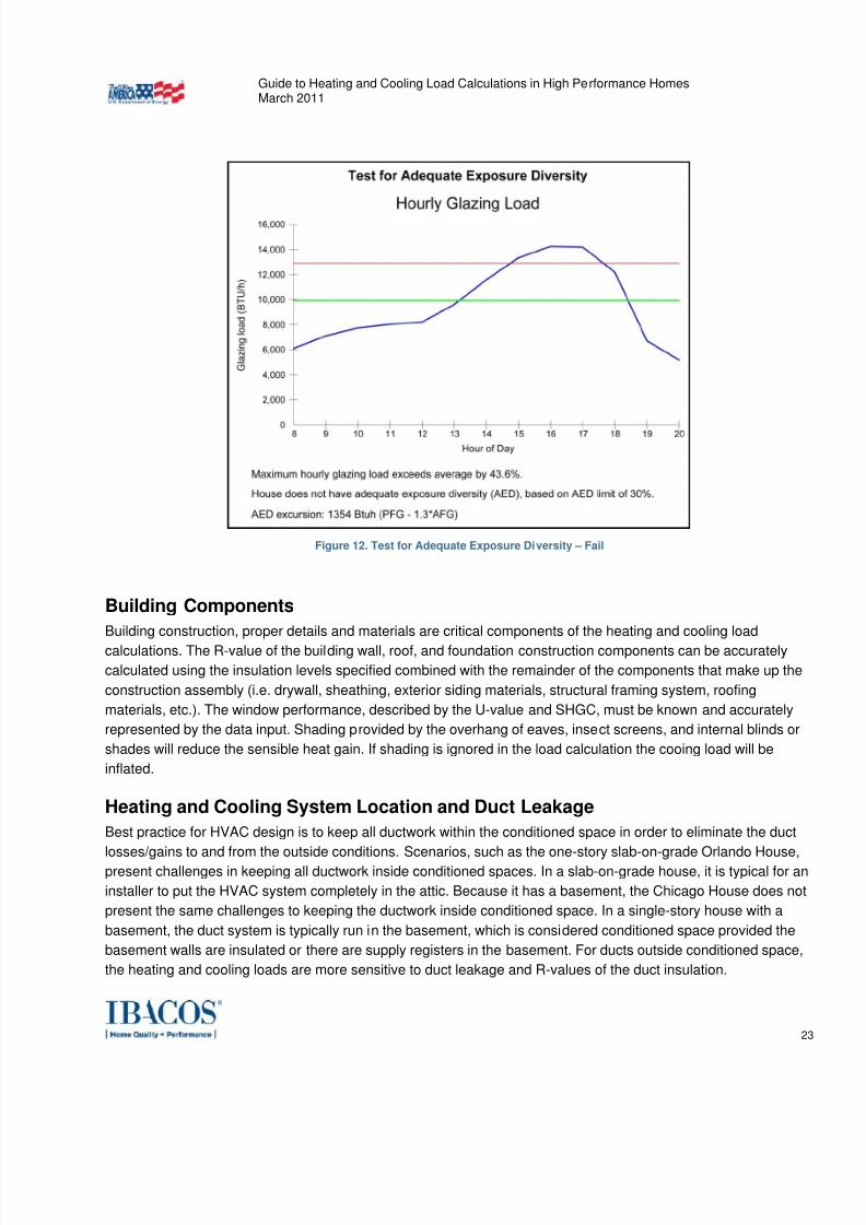
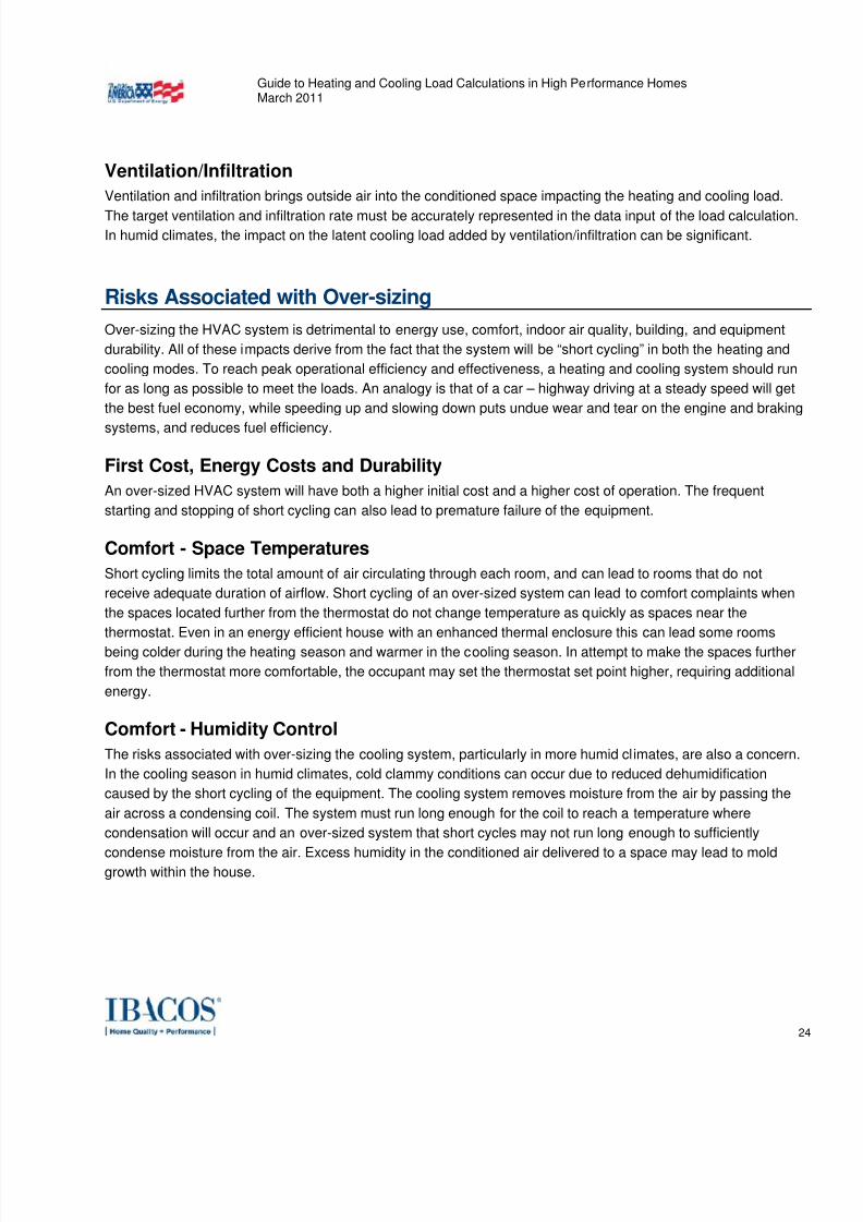
Figure 11 is a software generated output that shows a house passing the Test for Adequate Exposure Diversity
by not exceeding that maximum. Figure 12 shows a house that fails by slightly exceeding the AED limit late in the
day. The results of the Test for Adequate Exposure Diversity require appropriate design judgment in the
interpretation of the software output. Appendix 3 of the ACCA MJ8 describes the procedure to compensate for a
house that does not pass the Test for Adequate Exposure Diversity by compensating for the load only in those
rooms with the inadequate exposure diversity without over-sizing the whole system. If the variance shown in the
test is not addressed there will likely be a comfort issue in the rooms with the high glazing load.
Figure 11. Test for Adequate Exposure Diversity – Pass
Peak within limits
7/30/2019 vila load
http://slidepdf.com/reader/full/vila-load 23/46
7/30/2019 vila load
http://slidepdf.com/reader/full/vila-load 24/46
7/30/2019 vila load
http://slidepdf.com/reader/full/vila-load 25/46
Guide to Heating and Cooling Load Calculations in High Performance HomesMarch 2011
25
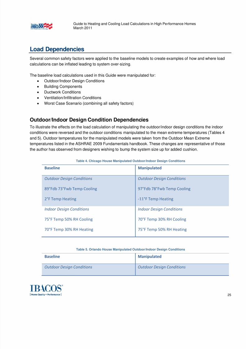
Load Dependencies
Several common safety factors were applied to the baseline models to create examples of how and where load
calculations can be inflated leading to system over-sizing.
The baseline load calculations used in this Guide were manipulated for:
• Outdoor/Indoor Design Conditions
• Building Components
• Ductwork Conditions
• Ventilation/Infiltration Conditions
• Worst Case Scenario (combining all safety factors)
Outdoor/Indoor Design Condition DependenciesTo illustrate the effects on the load calculation of manipulating the outdoor/indoor design conditions the indoor
conditions were reversed and the outdoor conditions manipulated to the mean extreme temperatures (Tables 4
and 5). Outdoor temperatures for the manipulated models were taken from the Outdoor Mean Extreme
temperatures listed in the ASHRAE 2009 Fundamentals handbook. These changes are representative of those
the author has observed from designers wishing to bump the system size up for added cushion.
Table 4. Chicago House Manipulated Outdoor/Indoor Design Conditions
Baseline Manipulated Outdoor Design Conditions 89°Fdb 73°Fwb Temp Cooling
2°F Temp Heating
Outdoor Design Conditions 97°Fdb 78°Fwb Temp Cooling
‐11°F Temp Heating
Indoor Design Conditions 75°F Temp 50% RH Cooling
70°F Temp 30% RH Heating
Indoor Design Conditions 70°F Temp 30% RH Cooling
75°F Temp 50% RH Heating
Table 5. Orlando House Manipulated Outdoor/Indoor Design Conditions
Baseline Manipulated Outdoor Design Conditions Outdoor Design Conditions
7/30/2019 vila load
http://slidepdf.com/reader/full/vila-load 26/46
7/30/2019 vila load
http://slidepdf.com/reader/full/vila-load 27/46
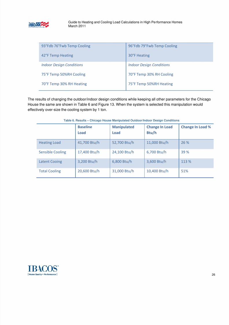
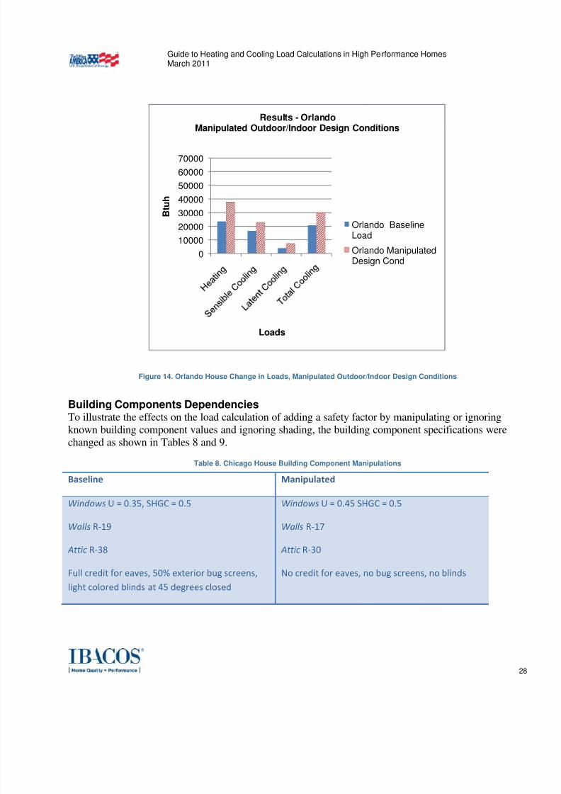
Guide to Heating and Cooling Load Calculations in High Performance HomesMarch 2011
27
Figure 13. Chicago House Change in Loads, Manipulated Outdoor/Indoor Design Conditions
The results of changing the outdoor/indoor design conditions while keeping all other parameters for the Orlando
House the same are shown in Table 7 and Figure 14. When the system is selected this manipulation would
effectively over-size the cooling system by 1 ton.
Table 7. Results - Orlando House Manipulated Outdoor/Indoor Design Conditions
Baseline Load
Manipulated Load
Change In Load Btu/h
Change In Load %
Heating Load 23,600 Btu/h 37,800 Btu/h 14,100 Btu/h 60 %
Sensible Cooling 16,600 Btu/h 22,900 Btu/h 6,300 Btu/h 38 %
Latent Cooing 4,100 Btu/h 7,100 Btu/h 3,000 Btu/h 73 %
Total
Cooling
20,700
Btu/h
30,100
Btu/h
9,400
Btu/h
45
%
0
10000
20000
30000
40000
50000
60000
70000
B t u h
Loads
Results - ChicagoManipulated Outdoor/Indoor Design Conditions
Chicago BaselineLoad
Chicago ManipulatedDesign Cond
7/30/2019 vila load
http://slidepdf.com/reader/full/vila-load 28/46
Guide to Heating and Cooling Load Calculations in High Performance HomesMarch 2011
28
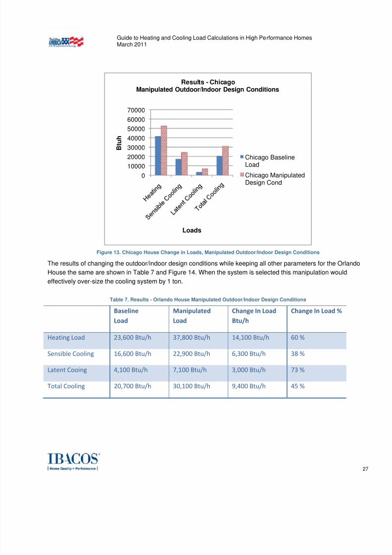
Figure 14. Orlando House Change in Loads, Manipulated Outdoor/Indoor Design Conditions
Building Components Dependencies
To illustrate the effects on the load calculation of adding a safety factor by manipulating or ignoringknown building component values and ignoring shading, the building component specifications were
changed as shown in Tables 8 and 9.
Table 8. Chicago House Building Component Manipulations
Baseline Manipulated Windows U = 0.35, SHGC = 0.5
Walls R‐19
Attic R‐38
Full credit for eaves, 50% exterior bug screens,
light colored blinds at 45 degrees closed
Windows U = 0.45 SHGC = 0.5
Walls R‐17
Attic R‐30
No credit for eaves, no bug screens, no blinds
0
10000
20000
30000
40000
50000
60000
70000
B t u h
Loads
Results - OrlandoManipulated Outdoor/Indoor Design Conditions
Orlando BaselineLoad
Orlando ManipulatedDesign Cond
7/30/2019 vila load
http://slidepdf.com/reader/full/vila-load 29/46
Guide to Heating and Cooling Load Calculations in High Performance HomesMarch 2011
29
Table 9. Orlando House Building Component Manipulations
Baseline Manipulated Windows U = 0.65, SHGC = 0.30
Walls Light weight concrete block w/ .75 inch
XPS, R‐4.8
Attic R‐31 sealed
Full credit for eaves, 50% exterior bug screens,
light colored blinds at 45 degrees closed
Windows U = 0.65 SHGC = 0.40
Walls Light weight concrete block no XPS R‐1
Attic R‐30 vented
No credit for eaves, no bug screens, no blinds
The wall R-value downgrade for the Chicago House is equivalent to the designer attempting to account for a poor
installation based on the RESNET Grade 3 installation quality level or ignoring the XPS for the Orlando House.
The attic insulation and window downgrade are equivalent to the designer not resetting default values or using
values lower that the IECC 2009 levels. These changes are representative of those the author has observed from
designers wishing to bump the system size up to for added cushion.
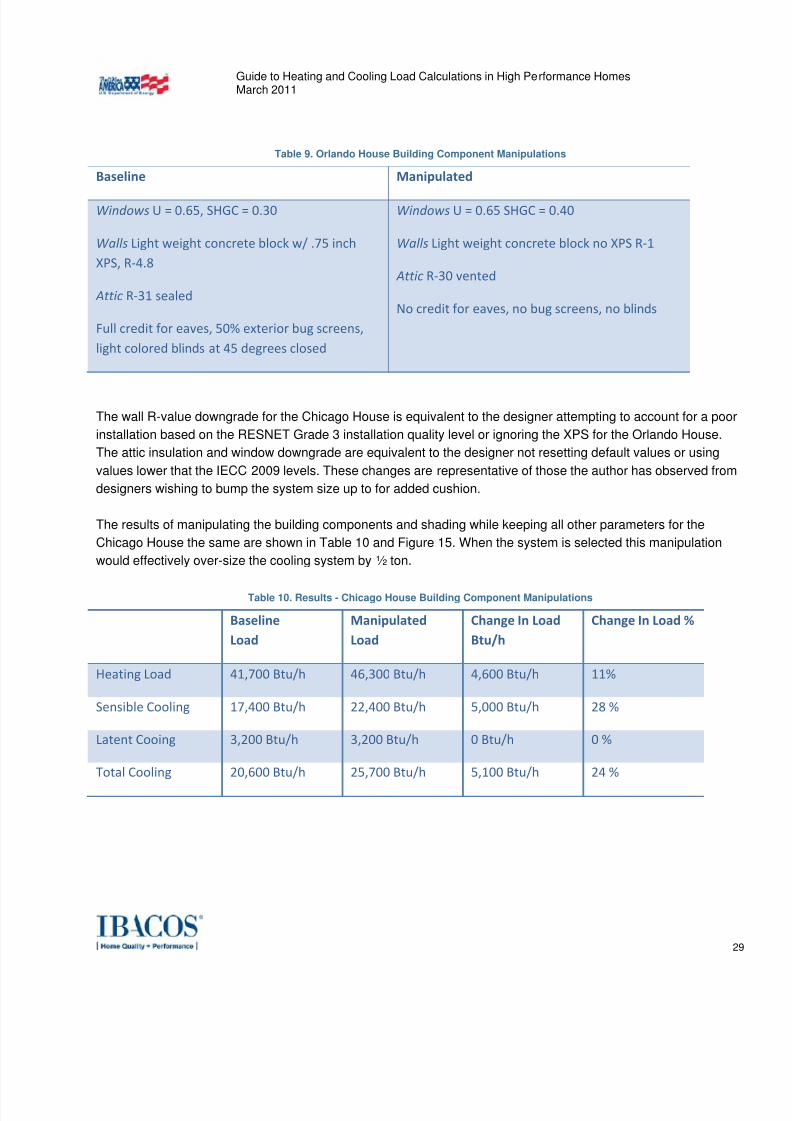
The results of manipulating the building components and shading while keeping all other parameters for the
Chicago House the same are shown in Table 10 and Figure 15. When the system is selected this manipulation
would effectively over-size the cooling system by ½ ton.
Table 10. Results - Chicago House Building Component Manipulations
Baseline Load
Manipulated Load
Change In Load Btu/h
Change In Load %
Heating Load 41,700 Btu/h 46,300 Btu/h 4,600 Btu/h 11%
Sensible Cooling 17,400 Btu/h 22,400 Btu/h 5,000 Btu/h 28 %
Latent Cooing 3,200 Btu/h 3,200 Btu/h 0 Btu/h 0 %
Total Cooling 20,600 Btu/h 25,700 Btu/h 5,100 Btu/h 24 %
7/30/2019 vila load
http://slidepdf.com/reader/full/vila-load 30/46
Guide to Heating and Cooling Load Calculations in High Performance HomesMarch 2011
30
Figure 15. Chicago House Change in Loads, Building Component Manipulations
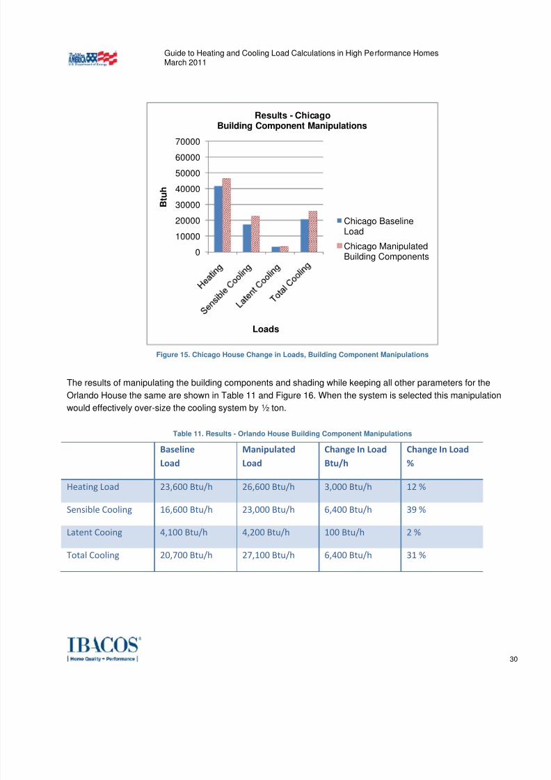
The results of manipulating the building components and shading while keeping all other parameters for the
Orlando House the same are shown in Table 11 and Figure 16. When the system is selected this manipulation
would effectively over-size the cooling system by ½ ton.
Table 11. Results - Orlando House Building Component Manipulations
Baseline Load
Manipulated Load
Change In Load Btu/h
Change In Load %
Heating Load 23,600 Btu/h 26,600 Btu/h 3,000 Btu/h 12 %
Sensible Cooling 16,600 Btu/h 23,000 Btu/h 6,400 Btu/h 39 %
Latent Cooing 4,100 Btu/h 4,200 Btu/h 100 Btu/h 2 %
Total Cooling 20,700 Btu/h 27,100 Btu/h 6,400 Btu/h 31 %
0
10000
20000
30000
40000
50000
60000
70000
B t u h
Loads
Results - ChicagoBuilding Component Manipulations
Chicago BaselineLoad
Chicago ManipulatedBuilding Components
7/30/2019 vila load
http://slidepdf.com/reader/full/vila-load 31/46
Guide to Heating and Cooling Load Calculations in High Performance HomesMarch 2011
31
Figure 16. Orlando House Change in Loads, Building Component Manipulations
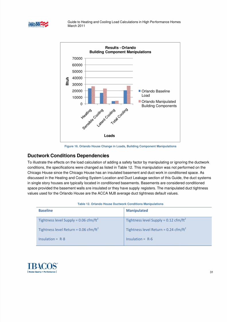
Ductwork Conditions Dependencies
To illustrate the effects on the load calculation of adding a safety factor by manipulating or ignoring the ductwork
conditions, the specifications were changed as listed in Table 12. This manipulation was not performed on theChicago House since the Chicago House has an insulated basement and duct work in conditioned space. As
discussed in the Heating and Cooling System Location and Duct Leakage section of this Guide, the duct systems
in single story houses are typically located in conditioned basements. Basements are considered conditioned
space provided the basement walls are insulated or they have supply registers. The manipulated duct tightness
values used for the Orlando House are the ACCA MJ8 average duct tightness default values.
Table 12. Orlando House Ductwork Conditions Manipulations
Baseline Manipulated Tightness level Supply = 0.06 cfm/ft2
Tightness level Return = 0.06 cfm/ft2
Insulation = R‐8
Tightness level Supply = 0.12 cfm/ft2
Tightness level Return = 0.24 cfm/ft2
Insulation = R‐6
0
10000
20000
30000
40000
50000
60000
70000
B t u h
Loads
Results - OrlandoBuilding Component Manipulations
Orlando BaselineLoad
Orlando ManipulatedBuilding Components
7/30/2019 vila load
http://slidepdf.com/reader/full/vila-load 32/46
Guide to Heating and Cooling Load Calculations in High Performance HomesMarch 2011
32
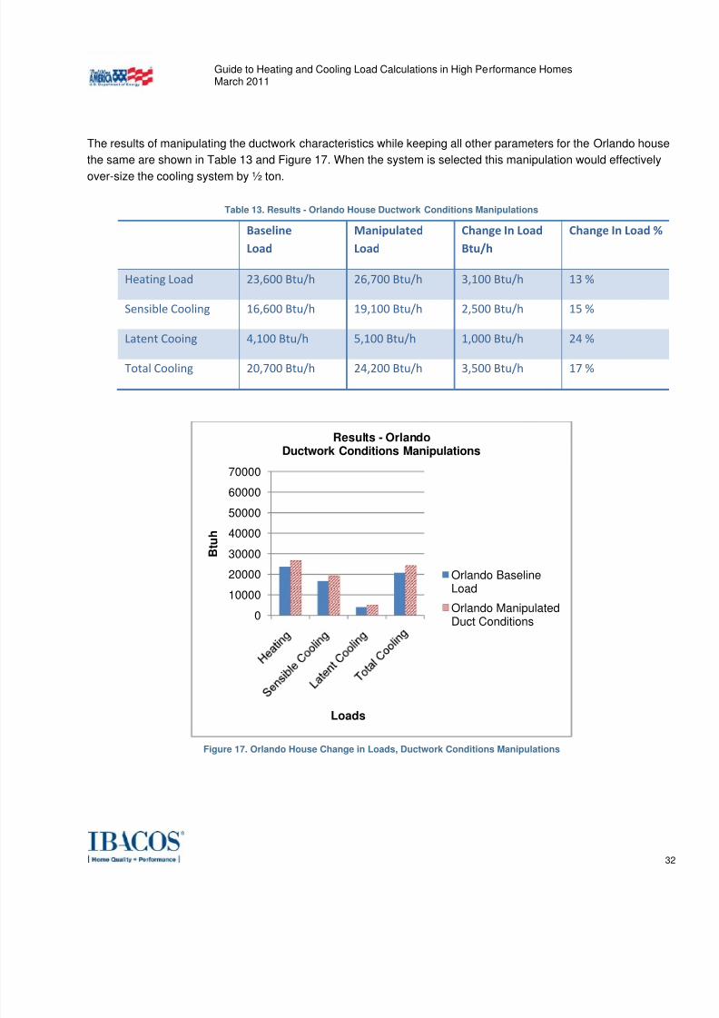
The results of manipulating the ductwork characteristics while keeping all other parameters for the Orlando house
the same are shown in Table 13 and Figure 17. When the system is selected this manipulation would effectively
over-size the cooling system by ½ ton.
Table 13. Results - Orlando House Ductwork Conditions Manipulations
Baseline Load
Manipulated Load
Change In Load Btu/h
Change In Load %
Heating Load 23,600 Btu/h 26,700 Btu/h 3,100 Btu/h 13 %
Sensible Cooling 16,600 Btu/h 19,100 Btu/h 2,500 Btu/h 15 %
Latent Cooing 4,100 Btu/h 5,100 Btu/h 1,000 Btu/h 24 %
Total Cooling 20,700 Btu/h 24,200 Btu/h 3,500 Btu/h 17 %
Figure 17. Orlando House Change in Loads, Ductwork Conditions Manipulations
0
10000
20000
30000
40000
50000
60000
70000
B t u h
Loads
Results - OrlandoDuctwork Conditions Manipulations
Orlando BaselineLoad
Orlando ManipulatedDuct Conditions
7/30/2019 vila load
http://slidepdf.com/reader/full/vila-load 33/46
Guide to Heating and Cooling Load Calculations in High Performance HomesMarch 2011
33
Ventilation/Infiltration Conditions Dependencies
To illustrate the effects on the load calculation of adding a safety factor by manipulating or ignoring the
ventilation/infiltration, Tables 14 and 15 show the specification changes using the ACCA MJ8 default infiltrationrate of “semi-loose construction” and a ventilation rate of an arbitrary continuous 100 cfm that may have been
determined by looking at the combined effect of simultaneously running all the exhaust fans in the house.
Table 14. Chicago House Ventilation/Infiltration Manipulations
Baseline Manipulated Heating season infiltration = 0.19 ACHn (5.04
ACH50)
Cooling season infiltration = 0.10 ACHn (2.65
ACH50)
Ventilation balanced 60 cfm to meet ASHRAE
standard 62.2 without energy or heat recovery
Heating season infiltration = 0.43 ACHn (11.39
ACH50)
Cooling season infiltration = 0.23 ACHn (6.09
ACH50)
Ventilation exhaust only 100 cfm
Table 15. Orlando House Ventilation/Infiltration Manipulations
Baseline Manipulated Heating season infiltration = 0.19 ACH (5.03
ACH50)
Cooling season infiltration = 0.10 ACH (2.65
ACH50)
Ventilation balanced 60 cfm to meet ASHRAE
standard 62.2 without energy or heat recovery
Heating season infiltration = 0.43 ACH (11.39
ACH50)
Cooling season infiltration = 0.23 ACH (6.09
ACH50)
Ventilation exhaust only 100 cfm
7/30/2019 vila load
http://slidepdf.com/reader/full/vila-load 34/46
Guide to Heating and Cooling Load Calculations in High Performance HomesMarch 2011
34
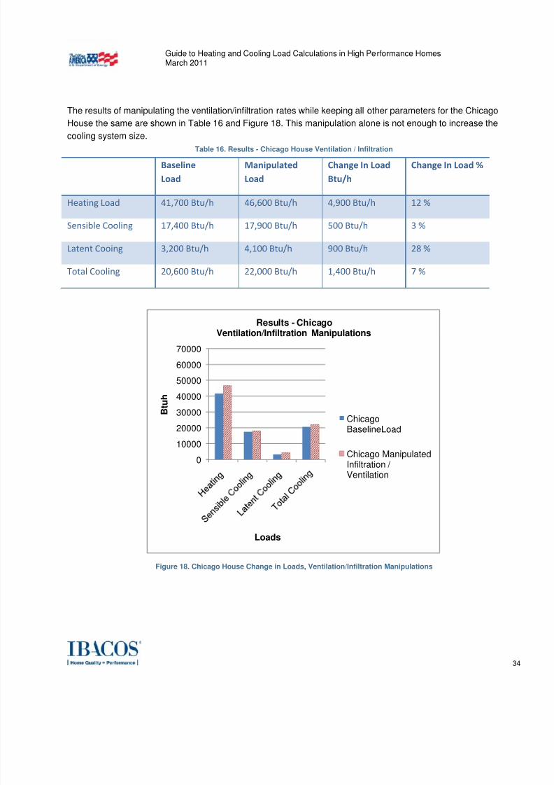
The results of manipulating the ventilation/infiltration rates while keeping all other parameters for the Chicago
House the same are shown in Table 16 and Figure 18. This manipulation alone is not enough to increase the
cooling system size.Table 16. Results - Chicago House Ventilation / Infiltration
Baseline Load
Manipulated Load
Change In Load Btu/h
Change In Load %
Heating Load 41,700 Btu/h 46,600 Btu/h 4,900 Btu/h 12 %
Sensible Cooling 17,400 Btu/h 17,900 Btu/h 500 Btu/h 3 %
Latent Cooing 3,200 Btu/h 4,100 Btu/h 900 Btu/h 28 %
Total
Cooling
20,600
Btu/h
22,000
Btu/h
1,400
Btu/h
7
%
Figure 18. Chicago House Change in Loads, Ventilation/Infiltration Manipulations
0
10000
20000
30000
40000
50000
60000
70000
B
t u h
Loads
Results - ChicagoVentilation/Infiltration Manipulations
ChicagoBaselineLoad
Chicago ManipulatedInfiltration / Ventilation
7/30/2019 vila load
http://slidepdf.com/reader/full/vila-load 35/46
Guide to Heating and Cooling Load Calculations in High Performance HomesMarch 2011
35
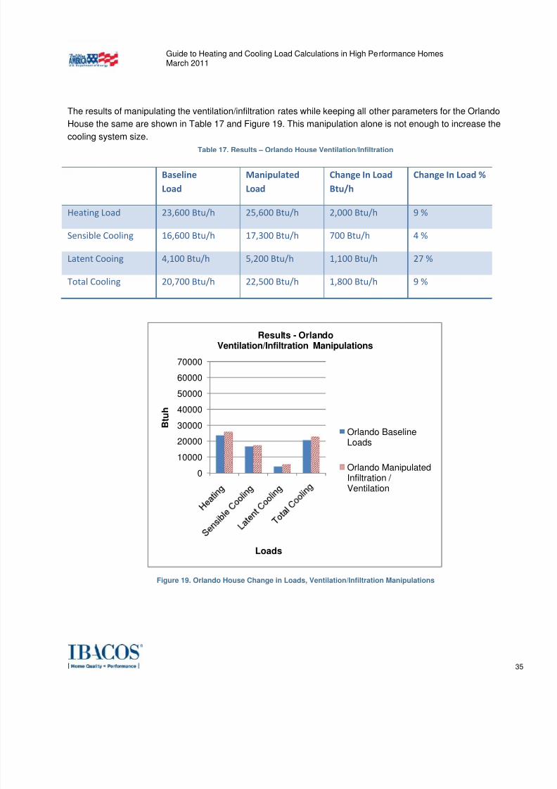
The results of manipulating the ventilation/infiltration rates while keeping all other parameters for the Orlando
House the same are shown in Table 17 and Figure 19. This manipulation alone is not enough to increase the
cooling system size.Table 17. Results – Orlando House Ventilation/Infiltration
Baseline Load
Manipulated Load
Change In Load Btu/h
Change In Load %
Heating Load 23,600 Btu/h 25,600 Btu/h 2,000 Btu/h 9 %
Sensible Cooling 16,600 Btu/h 17,300 Btu/h 700 Btu/h 4 %
Latent Cooing 4,100 Btu/h 5,200 Btu/h 1,100 Btu/h 27 %
Total Cooling
20,700
Btu/h
22,500
Btu/h
1,800
Btu/h
9 %
Figure 19. Orlando House Change in Loads, Ventilation/Infiltration Manipulations
0
10000
20000
30000
40000
50000
60000
70000
B t u
h
Loads
Results - OrlandoVentilation/Infiltration Manipulations
Orlando BaselineLoads
Orlando ManipulatedInfiltration / Ventilation
7/30/2019 vila load
http://slidepdf.com/reader/full/vila-load 36/46
Guide to Heating and Cooling Load Calculations in High Performance HomesMarch 2011
36
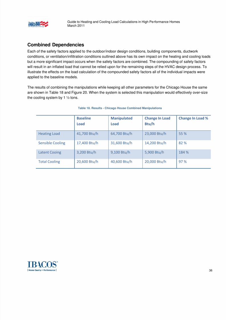
Combined Dependencies
Each of the safety factors applied to the outdoor/indoor design conditions, building components, ductwork
conditions, or ventilation/infiltration conditions outlined above has its own impact on the heating and cooling loadsbut a more significant impact occurs when the safety factors are combined. The compounding of safety factors
will result in an inflated load that cannot be relied upon for the remaining steps of the HVAC design process. To
illustrate the effects on the load calculation of the compounded safety factors all of the individual impacts were
applied to the baseline models.
The results of combining the manipulations while keeping all other parameters for the Chicago House the same
are shown in Table 18 and Figure 20. When the system is selected this manipulation would effectively over-size
the cooling system by 1 ½ tons.
Table 18. Results - Chicago House Combined Manipulations
Baseline Load
Manipulated Load
Change In Load Btu/h
Change In Load %
Heating Load 41,700 Btu/h 64,700 Btu/h 23,000 Btu/h 55 %
Sensible Cooling 17,400 Btu/h 31,600 Btu/h 14,200 Btu/h 82 %
Latent Cooing 3,200 Btu/h 9,100 Btu/h 5,900 Btu/h 184 %
Total Cooling 20,600 Btu/h 40,600 Btu/h 20,000 Btu/h 97 %

7/30/2019 vila load
http://slidepdf.com/reader/full/vila-load 37/46
7/30/2019 vila load
http://slidepdf.com/reader/full/vila-load 38/46
Guide to Heating and Cooling Load Calculations in High Performance HomesMarch 2011
38
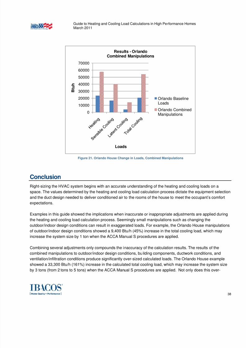
Figure 21. Orlando House Change in Loads, Combined Manipulations
Conclusion
Right-sizing the HVAC system begins with an accurate understanding of the heating and cooling loads on a
space. The values determined by the heating and cooling load calculation process dictate the equipment selection
and the duct design needed to deliver conditioned air to the rooms of the house to meet the occupant’s comfort
expectations.
Examples in this guide showed the implications when inaccurate or inappropriate adjustments are applied during
the heating and cooling load calculation process. Seemingly small manipulations such as changing the
outdoor/indoor design conditions can result in exaggerated loads. For example, the Orlando House manipulations
of outdoor/indoor design conditions showed a 9,400 Btu/h (45%) increase in the total cooling load, which may
increase the system size by 1 ton when the ACCA Manual S procedures are applied.
Combining several adjustments only compounds the inaccuracy of the calculation results. The results of the
combined manipulations to outdoor/indoor design conditions, building components, ductwork conditions, and
ventilation/infiltration conditions produce significantly over-sized calculated loads. The Orlando House example
showed a 33,300 Btu/h (161%) increase in the calculated total cooling load, which may increase the system size
by 3 tons (from 2 tons to 5 tons) when the ACCA Manual S procedures are applied. Not only does this over-
0
10000
20000
30000
40000
50000
60000
70000
B t u h
Loads
Results - OrlandoCombined Manipulations
Orlando BaselineLoads
Orlando CombinedManipulations
7/30/2019 vila load
http://slidepdf.com/reader/full/vila-load 39/46
Guide to Heating and Cooling Load Calculations in High Performance HomesMarch 2011
39
sizing impact the heating and cooling equipment costs, but duct sizes and numbers of runs must also be
increased to account for the significantly increased system airflow.
Again, ACCA MJ8 says of compounding safety factors:
“Research studies and the experience of multiple system designers indicate that aggressive use of Manual J
procedures provides adequate accuracy. No additional safety factors are required when load estimates are based
on accurate information pertaining to the envelope construction and duct system efficiency. Large errors are
possible if there is uncertainty about insulation levels, fenestration performance, envelope tightness or the
efficiency of the duct runs installed in the unconditioned space.”
The compounding of arbitrary safety factors must be avoided in the load calculation process. The HVAC design
industry’s practice of using extreme outdoor design conditions, de-rating the insulation value, and over-estimating
the infiltration rate render the calculated load values meaningless.

7/30/2019 vila load
http://slidepdf.com/reader/full/vila-load 40/46
Guide to Heating and Cooling Load Calculations in High Performance HomesMarch 2011
40
References
O’Neal, Dennis L. et.al. ASHRAE 2009 Fundamentals Volume. Atlanta, GA: ASHRAE. 2009.
Rutkowowski P.E., Hank. Manual J Residential Load Calculation Eighth Edition Version Two. Arlington, VA:
ACCA. 2006
National Renewable Energy Laboratory (NREL). Typical Meteorological Year 3 Data Set. NREL Website.
http://rredc.nrel.gov/solar/old_data/nsrdb/1991-2005/tmy3/. 2008.

7/30/2019 vila load
http://slidepdf.com/reader/full/vila-load 41/46
Guide to Heating and Cooling Load Calculations in High Performance HomesMarch 2011
41
List of Appendices
Appendix A: Enhancements to Scope for Mechanical Contractor/HVAC Manual J Designer
Appendix B: Title
7/30/2019 vila load
http://slidepdf.com/reader/full/vila-load 42/46
7/30/2019 vila load
http://slidepdf.com/reader/full/vila-load 43/46
Guide to Heating and Cooling Load Calculations in High Performance HomesMarch 2011
43
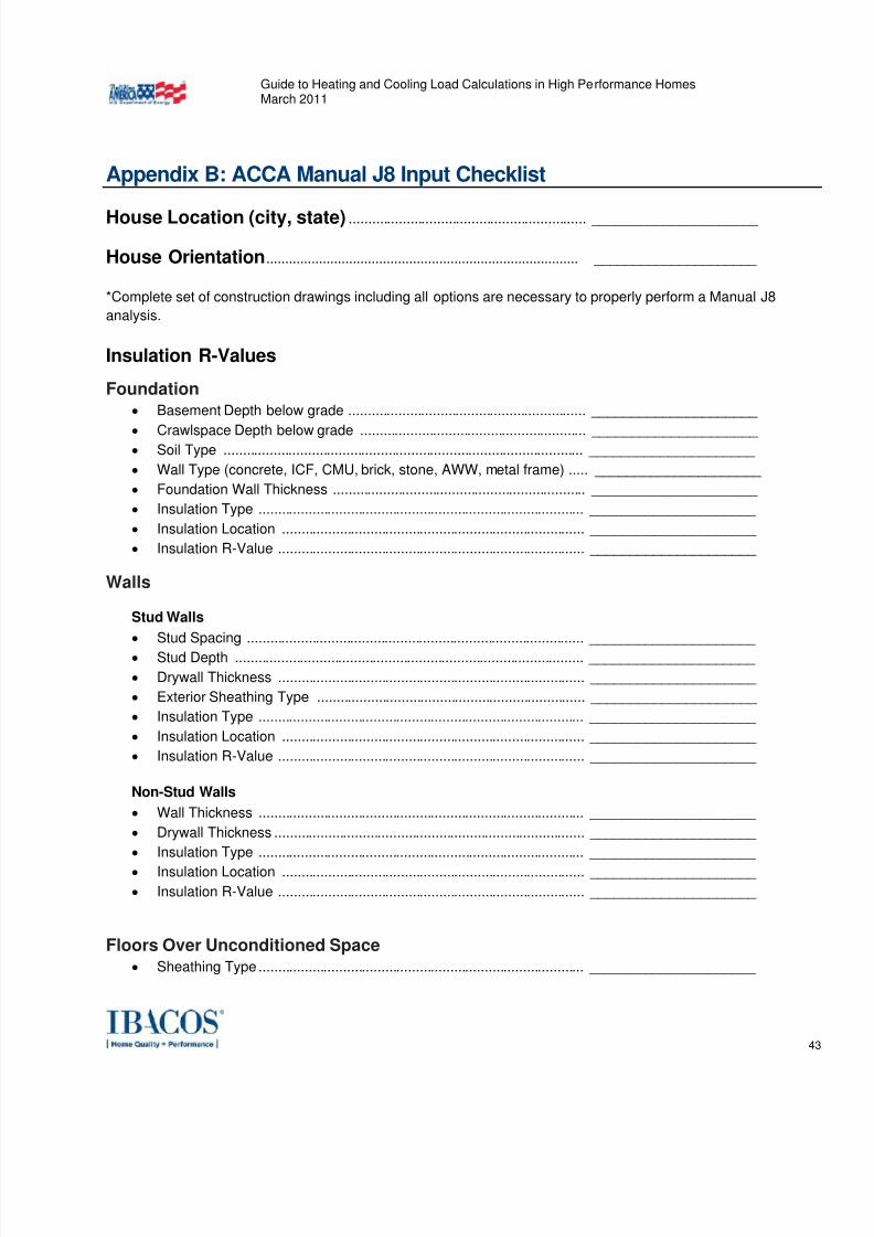
Appendix B: ACCA Manual J8 Input Checklist
House Location (city, state) .............................................................. _____________________
House Orientation................................................................................... _____________________
*Complete set of construction drawings including all options are necessary to properly perform a Manual J8
analysis.
Insulation R-Values
Foundation
• Basement Depth below grade .............................................................. _____________________
• Crawlspace Depth below grade ........................................................... _____________________ • Soil Type .............................................................................................. _____________________
• Wall Type (concrete, ICF, CMU, brick, stone, AWW, metal frame) ..... _____________________
• Foundation Wall Thickness .................................................................. _____________________
• Insulation Type ..................................................................................... _____________________
• Insulation Location ............................................................................... _____________________
• Insulation R-Value ................................................................................ _____________________
Walls
Stud Walls
• Stud Spacing ........................................................................................ _____________________
• Stud Depth ........................................................................................... _____________________
• Drywall Thickness ................................................................................ _____________________
• Exterior Sheathing Type ...................................................................... _____________________
• Insulation Type ..................................................................................... _____________________
• Insulation Location ............................................................................... _____________________
• Insulation R-Value ................................................................................ _____________________
Non-Stud Walls
• Wall Thickness ..................................................................................... _____________________
• Drywall Thickness ................................................................................. _____________________
• Insulation Type ..................................................................................... _____________________
• Insulation Location ............................................................................... _____________________
• Insulation R-Value ................................................................................ _____________________
Floors Over Unconditioned Space
• Sheathing Type ..................................................................................... _____________________
7/30/2019 vila load
http://slidepdf.com/reader/full/vila-load 44/46
Guide to Heating and Cooling Load Calculations in High Performance HomesMarch 2011
44
• Insulation Type ..................................................................................... _____________________
• Insulation Location ............................................................................... _____________________
•
Insulation R-Value ................................................................................ _____________________
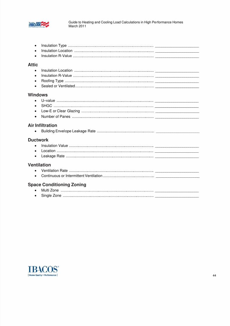
Attic
• Insulation Location ............................................................................... _____________________
• Insulation R-Value ................................................................................ _____________________
• Roofing Type ........................................................................................ _____________________
• Sealed or Ventilated .............................................................................. _____________________
Windows
• U–value ................................................................................................ _____________________
• SHGC ................................................................................................... _____________________
• Low-E or Clear Glazing ........................................................................ _____________________
• Number of Panes ................................................................................. _____________________
Air Infiltration
• Building Envelope Leakage Rate ......................................................... _____________________
Ductwork
• Insulation Value .................................................................................... _____________________
• Location ................................................................................................ _____________________
• Leakage Rate ....................................................................................... _____________________
Ventilation
• Ventilation Rate .................................................................................... _____________________ • Continuous or Intermittent Ventilation ................................................... _____________________
Space Conditioning Zoning• Multi Zone ............................................................................................ _____________________
• Single Zone .......................................................................................... _____________________
7/30/2019 vila load
http://slidepdf.com/reader/full/vila-load 45/46
Guide to Heating and Cooling Load Calculations in High Performance HomesMarch 2011
45

7/30/2019 vila load
http://slidepdf.com/reader/full/vila-load 46/46
Guide to Heating and Cooling Load Calculations in High Performance HomesMarch 2011
About IBACOS ®
IBACOS enables production builders to improve the quality and performance of their homes by providing ‘whole
house’ expert services, e-tools and information. Our building science-based team of specialists provide technical
and business management expertise in three business areas:
Quality Assurance – Implementing a comprehensive quality program
Risk Management - Solving immediate construction defect issues
Performance Coaching - Taking steps to achieve higher standards.
To catalyze tomorrow’s best practices and expand on its efforts as a team leader for the U.S. Department ofEnergy’s Building America program, IBACOS has assembled its Best Practices Research Alliance, a collaborative
innovation ‘community’ of leading builders and suppliers.
Contact
Arlan Burdick EIT, LEED ®
AP BD+C
Building Performance Specialist, IBACOS
406-548-7472