Embed Size (px)
Citation preview


VIKING CHAINSpage 2
Viking Chains Inc…. a real sharp chain company.
The Viking Chains Group is a manufacturer and wholesaler of industrial steel chain and relatedproducts. Established in 1993, the Group includes Viking Chains Inc., VC Chains Corporation, and VC Chains Enviro Group.
Viking Chains head office, manufacturing facility and main warehouse are located in Delta, BC, with a stocking warehouse and sales office in Quebec City, Quebec.
VC Chains is headquartered in Acworth, Georgia, with a 15,000-sq. ft. stocking warehouse and salesoffice. Similarly, we have a sales office and warehouse in Vancouver, Washington. VC Chains alsocontracts numerous manufacturers reps strategically located in the USA.
VC Chains Enviro Group is a division of Viking Chains, manufacturing and supplying all thecomponents for rectangular clarifiers, bar screens and related products to the Water and Wastewaterindustry throughout North America.
The Viking Chains Group has a diverse customer base that includes the wood, food packaging,cement, sugar, waste water and agricultural industries. We bring our products to market throughdistibutors and original equipment manufacturers. We remain connected intimately to our customersthrough contact with end users.
Viking Chains also exports regularly to a number of customer's and strategicalliance partners in many countries around the world.
As a manufacturer of specialty chains,attachments, sprockets and shaftassemblies, our sales and engineering staff are able to recommend and assist our customers in their most difficult and arduous applications.
By displaying the registered Viking brand on all our products, and committed to the high standards of ISO quality management we assure our customers of our commitment anddedication to continuous productquality.
The Viking Chain Group maintains acorporate philosophy of "being where you need to be, when you need to bethere" and by that we guarantee that our technical support team will be at our customers door for support or trouble shooting anytime, anywhere in the world.
Cliff LanePresident Viking Chains Group

TABLE OF CONTENTSpage 3
4 Chains Construction & Components
5 Standard Packaging & Ordering Information
6 Standard Roller Chains . . . . . . . . . . . . . . . . . . . . . . . . . . . . . . .25 - 240-3
7 Heavy Duty Chains - H Series . . . . . . . . . . . . . . . . . . . . . . . . . .25H - 160H-2
8 Heavy Duty Chains - SH Series . . . . . . . . . . . . . . . . . . . . . . . . .80SH - 200SH-3
9 Heavy Duty Chains - EX Series . . . . . . . . . . . . . . . . . . . . . . . . .80 EX - 240 EX-3
10 Heavy Duty Chains - EXH Series . . . . . . . . . . . . . . . . . . . . . . .80 EXH - 200 EXH-3
11 RS Double Pitch Chains . . . . . . . . . . . . . . . . . . . . . . . . . . . . . .A2040 - A2060
12 Double Pitch Conveyor Chains . . . . . . . . . . . . . . . . . . . . . . . .C2040 - C2162H
13 Straight Sidebar, Rollerless Chains . . . . . . . . . . . . . . . . . . . . .40F - 120F, 55 - 125
14 Nickel Plated Standard Chains . . . . . . . . . . . . . . . . . . . . . . . . .25NP - 160NP
15 Nickel Plated Double Pitch Chains . . . . . . . . . . . . . . . . . . . . .C2040NP - C2160H NP
16 Stainless Steel Standard Chains . . . . . . . . . . . . . . . . . . . . . . . .25SS - 120SS
17 Stainless Steel Double Pitch Chains . . . . . . . . . . . . . . . . . . . . .C2040SS - C2082H SS
18 Mega SS Standard Chains . . . . . . . . . . . . . . . . . . . . . . . . . . . .40SS MEGA - 80-2SS MEGA
19 Self Lube Chains . . . . . . . . . . . . . . . . . . . . . . . . . . . . . . . . . . . .40SL - 80SL, C2040 SL - C2082H SL
20 Hollow Pin Chains . . . . . . . . . . . . . . . . . . . . . . . . . . . . . . . . . . .40HP - 80HP, C2040 HP - C2082 HP
21 Sidebow Chains . . . . . . . . . . . . . . . . . . . . . . . . . . . . . . . . . . . .35SB - 60-SB
22 British Standard Chains . . . . . . . . . . . . . . . . . . . . . . . . . . . . . .05B - 48B-3
23 Leaf Chains - General Info
24 Light Duty Leaf Chains . . . . . . . . . . . . . . . . . . . . . . . . . . . . . . .AL422 - AL1266
25 Heavy Duty Leaf Chains . . . . . . . . . . . . . . . . . . . . . . . . . . . . . .BL423 - BL1666
26 Standard Roller Chains Attachments . . . . . . . . . . . . . . . . . . .Parts Configuration
27 Standard Roller Chains Attachments . . . . . . . . . . . . . . . . . . .Attachment Spacing, Applications
28 Standard Roller Chains Attachments . . . . . . . . . . . . . . . . . . .35 - 160 A-1, K-1, SA-1, SK-1, D-1, D-3
29 Standard Roller Chains Wide Contour Attachments . . . . . .35 - 160 WA-1 - WSK-1, WA-2 - WSK-2
30 Mega Chains
31 Mega Chains Standard Attachments . . . . . . . . . . . . . . . . . . .40SS - 80SS Mega A-1, K-1, SA-1, SK-1
32 Mega Chains Wide Contour Attachments . . . . . . . . . . . . . . .40SS - 80SS Mega - WA-1, WK-1, WSA-1, WSK-2
40SS - 80SS Mega WA-2, WK-2, WSA-2, WSK-2
33 Double Pitch Chains Attachments . . . . . . . . . . . . . . . . . . . . . .C2040 - C2082H A-1, K-1, SA-1, SK-1, D-1, D-3
34 Double Pitch Chains Attachments . . . . . . . . . . . . . . . . . . . . . .C2040 - C2082H A-2, K-2, SA-2, SK-2
35 Special Market Chains . . . . . . . . . . . . . . . . . . . . . . . . . . . . . . .C2050 - C2060 Triple Speed
36 Special Market Chains . . . . . . . . . . . . . . . . . . . . . . . . . . . . . . .Citrus (C2060H D-5) Double Flex (DF3500)
37 Special Market Chains . . . . . . . . . . . . . . . . . . . . . . . . . . . . . . .Trimmer, Malleable, Combination Chains
38 Chains Tools
39 Engineering Data . . . . . . . . . . . . . . . . . . . . . . . . . . . . . . . . . .Chain Selection
40 Engineering Data . . . . . . . . . . . . . . . . . . . . . . . . . . . . . . . . . .Chain Selection
41 Engineering Data . . . . . . . . . . . . . . . . . . . . . . . . . . . . . . . . . .Chain Selection Chart
42 Engineering Data . . . . . . . . . . . . . . . . . . . . . . . . . . . . . . . . . .Lubrication
43 Chains Warning Statement, Terms and Conditions

CHAIN CONSTRUCTION & COMPONENTSpage 4
t Roller Chain consists of pins, bushings, rollers and link plates as illustrated below
Pin requires highwear resistance andshearing strength tosupport the entireload acting on thechain
Bushing receivesmassive forces fromother components ofthe chain and mustprovide wearresistance and fatigue strength
Roller requires highshock strength,collapse strength andwear resistance toprotect the chain fromheavy shock of thesprocket and also inorder to articulate thechains smoothly whenengaged with thesprocket
Link plate receivesdirect tension of thechain with occasionallarge shock on powertransmission,therefore requireshigh tensile strength,shock resistance, andfatigue strength
Connecting Link(Spring Clip type)
Connecting Link(Cotter Pin type)
Connecting Link(Duplex)
Offset Link Offset Link(Duplex)
Two Pitch Offset Link
Connecting Link allows easyinstallation or removal of a rollerchain with an even number ofpitches. Spring Clips or Cotter Pinsare used to retain the connectingpins.
Offset Link are used to adjust thelengths of the chain with an oddnumber of pitches. It is notrecommended to use Offset Links.Whenever possible, use chain withan even number of pitches.
Two Pitch Offset Link is acombination of an inner link andoffset link, which is stronger thanOne Pitch Offset Link.

STANDARD PACKAGING & ORDERING INFOpage 5
STANDARD PACKAGING
Ordering Cut to Length Strands: If length in pitches required is known. Please call our service personnel foraid in ordering if only length in inches, feet, or metric length is known
Advise Configuration
Number of Links (Pitches) in Package
25 0.250 480 1200 2400 4800
35 0.375 320 800 1600 3200
40 0.500 240 600 1200 2400
41 0.500 240 600 1200 2400
50 0.625 192 480 960 1920
60 0.750 160 400 800 1600
80 1.000 120 300 600
100 1.250 96 240 480
120 1.500 80
140 1.750 68
160 2.000 60
180 2.250 54
200 2.500 48
240 3.000 40
Chain
Size
Chain
Pitch
Standard
10’ Box 25’ Reel
Standard Reels
50’ Reel 100’ Reel
10' BoxNormal stocking ofroller chain will bein 10' Box withproper productidentification.
Reel or CoilAvailable in coils orreels, coiled aroundwooden or wirespool, normally 25',50' or 100'depending on sizeof chain and weight.
Terms Description of Assembly
RLEEOdd No. of Pitches
Inc Conn Link (Master Link)Each End
Even No. of Pitches
Roller Link each endexact amount of links (pitches) will end with roller link each end of strand,
no connecting link or offset link will be supplied
Pitches including connecting linkexact amount of links (pitches) will include a loose connecting link
(master link) at the end of strand
Pitches including connecting link each endexact amount of links (pitches) will include a loose connecting link (master link)
at both ends of strand
Pitches including connecting link (master link) assembled endlessexact amount of links (pitches) will include conn link assembled into endless loop
Pitches riveted endlessexact amount of links (pitches) will be supplied with no connecting or offset link butwill be riveted into endless loop using riveted pin link and roller link within the chain
Pitches including connecting link (master link) and offset linkexact amount of pitches ordered will include an offset link assembled onto chain
and a loose connecting link (master link) will be supplied
Inc Conn Link (Master Link)Even No. of Pitches
Inc Conn Link ( Master Link)Assembled EndlessEven No. of Pitches
Riveted EndlessEven No. of Pitches
Inc C/L & O/LOdd No. of Pitches

STANDARD ROLLER CHAINS
T
T
C
G/G
IF
C
W
R D
D
T
T
G1
W
VikingANSI #
RollerWidth Height
RollerDia
Transverse
PITCH
Avg UltStrength
Lbs/Ft
Approx WeightLbs/Ft
Dia LengthsLink Plates PinPitch
ThicknessP W R H1 H2 T D F G G1 C
R D
T
W
T
C
GF
PH
2
H1
P
25 0.250 0.125 0.130 0.197 0.228 0.03 0.091 0.150 0.189 - - - - 990 0.09425-2 0.277 0.316 - - - 0.252 1,980 0.17525-3 0.402 0.441 - - - 0.252 2,970 0.269
35 0.375 0.188 0.200 0.299 0.354 0.047 0.141 0.228 0.276 0.299 - - - 2,310 0.22235-2 0.425 0.472 0.500 0.398 4,620 0.46435-3 0.626 0.730 0.685 0.398 6,930 0.704
41 0.500 0.250 0.306 0.335 0.382 0.047 0.141 0.260 0.313 0.335 - - - 2,640 0.27540 0.500 0.312 0.312 0.402 0.465 0.06 0.156 0.323 0.368 0.394 - 4,070 0.45640-2 0.602 0.669 0.693 0.567 8,140 0.79940-3 0.892 0.937 0.967 0.567 12,120 1.189
50 0.625 0.375 0.400 0.512 0.583 0.079 0.190 0.398 0.459 0.496 - 6,820 0.67850-2 0.756 0.815 0.831 0.713 13,640 1.37050-3 1.114 1.167 1.189 0.713 20,460 2.049
60 0.750 0.500 0.469 0.610 0.689 0.094 0.234 0.492 0.557 0.606 - 9,680 0.96760-2 0.945 1.004 1.059 0.898 19,360 2.03560-3 1.392 1.455 1.482 0.898 29,040 3.073
80 1.000 0.625 0.625 0.803 0.941 0.122 0.313 0.634 0.699 0.740 - 17,160 1.61280-2 1.205 1.268 1.323 1.154 34,320 3.53380-3 1.783 1.850 1.890 1.154 51,480 5.240
100 1.250 0.750 0.750 0.976 1.185 0.154 0.375 0.791 - 0.909 - 26,007 2.512100-2 1.496 - 1.614 1.409 52,015 5.038100-3 2.200 - 2.319 1.409 78,020 7.524
120 1.500 1.000 0.875 1.181 1.378 0.185 0.437 0.992 - 1.126 - 34,100 4.150120-2 1.886 - 2.020 1.787 68,200 8.230120-3 2.780 - 2.913 1.787 102,300 12.290
140 1.750 1.000 1.000 1.425 1.654 0.220 0.500 1.075 - - - - - 47,300 5.032140-2 2.037 - - - - 1.925 94,600 9.962140-3 - - - - 1.925 141,900 14.752
160 2.000 1.250 1.125 1.630 1.890 0.252 0.562 1.281 - 1.467 - 60,500 6.770160-2 2.430 - 2.618 2.303 121,000 13.430160-3 3.585 - 3.770 2.303 181,500 20.130
180 2.250 1.406 1.406 1.842 2.134 0.280 0.687 1.402 - - - 1.642 - 81,610 9.220180-2 2.697 - - - 2.937 2.591 163,200 18.326180-3 3.992 - - - 4.232 2.591 244,800 27.426
200 2.500 1.562 1.562 2.047 2.374 0.315 0.781 1.531 - - - 1.811 - 105,900 11.312200-2 2.941 - - - 3.22 2.819 211,500 22.470200-3 4.35 - - - 4.63 2.819 317,400 33.622
240 3.000 1.875 1.875 2.457 2.850 0.374 0.937 1.858 - - - 2.157 - 152,200 16.509240-2 3.587 - - - 3.886 3.457 304,200 32.817240-3 5.315 - - - 5.614 3.457 456,400 49.125
page 6
t Additional Multiple Strand Chains
(-4 thru -6) are available
from our factories or for
special stocking arrangements.
Consult your Viking Service Center
for special handling
R
R

HEAVY DUTY CHAINS HEAVY SERIES
VikingANSI #
RollerWidth
RollerDia
Transverse
PITCH
Avg UltStrength
Lbs/Ft
Approx WeightLbs/Ft
Dia LengthsHeightLink Plates PinPitch
ThicknessP W R H1 H2 T D F G G1 C
25-H 0.250 0.125 0.130 0.197 0.228 0.039 0.090 0.177 0.200 - - - - - - 1,232 0.11415-H 0.500 0.188 0.306 0.402 0.465 0.059 0.156 0.252 0.307 - - - - - - 4,070 0.34
50H 0.625 0.375 0.400 0.512 0.583 0.094 0.199 0.429 0.488 0.508 - - - 6,820 0.75
60H 0.750 0.500 0.469 0.610 0.689 0.122 0.234 0.555 0.618 0.654 - 9,680 1.2160H-2 1.070 1.134 1.169 1.028 19,360 2.39
80H 1.000 0.625 0.625 0.819 0.945 0.154 0.313 0.705 - - - 0.819 - 17,600 1.9880H-2 1.346 - - - 1.461 1.283 35,200 3.92
100H 1.250 0.750 0.750 0.976 1.185 0.185 0.375 0.854 - - - 0.980 - 26,400 2.98100H-2 1.624 - - - 1.750 1.539 52,800 5.59
120H 1.500 1.000 0.875 1.180 1.378 0.220 0.437 1.062 - - - 1.204 - 35,200 4.55120H-2 2.024 - - - 2.167 1.925 70,400 9.02
140H 1.750 1.000 1.000 1.430 1.654 0.252 0.500 1.138 - - - 1.303 - 47,300 5.44140H-2 2.171 - - - 2.325 2.055 94,600 10.80
160H 2.000 1.250 1.125 1.630 1.890 0.283 0.562 1.344 - - - 1.530 - 60,500 7.29160H-2 2.563 - - - 2.748 2.437 121,000 13.98
t ANSI Heavy Series Chains differ from standard roller chains in the extra thickness of link plates
t The thicker plates provide greater shock load resistance and fatigue strength
t These chains are used in heavy duty applications
DR
G T
T
G1
F W
R D
T
W
T
C
GF
P
H2
H1
P
page 7

80SH 1.00 0.63 0.625 0.819 0.949 0.157 0.313 0.699 0.821 - 3,980 22,050 2.1180SH-2 1.341 1.463 1.283 6,750 44,060 4.2080SH-3 1.982 2.104 9,900 66,090 6.28
100-SH 1.25 0.75 0.750 1.024 1.185 0.189 0.376 0.839 0.969 - 5,750 32,600 3.10100SH-2 1.608 1.738 1.539 9,730 65,200 6.17100SH-3 2.378 2.508 14,300 97,800 9.23
120SH 1.50 0.88 0.875 1.228 1.425 0.220 0.437 1.039 1.177 - 7,500 44,060 4.47120SH-2 2.002 2.140 1.925 12,750 88,100 8.90120SH-3 2.965 3.102 18,750 132,200 13.32
140SH 1.75 1.00 1.000 1.433 1.661 0.252 0.500 1.106 1.299 - 9,700 57,300 5.69140SH-2 2.134 2.327 2.055 16,500 115,000 11.32140SH-3 3.161 3.354 24,300 172,000 16.95
160SH 2.00 1.25 1.125 1.638 1.898 0.280 0.563 1.303 1.500 - 12,300 72,900 7.40160SH-2 2.522 2.719 2.437 21,000 145,500 14.73160SH-3 3.740 3.937 30,800 218,300 22.06
200SH 2.50 1.50 1.562 2.047 2.374 0.374 0.781 1.663 1.943 - 17,850 130,200 11.90 200SH-2 3.205 3.484 3.083 30,400 260,100 25.33200SH-3 4.746 5.026 44,800 390,300 37.92
HEAVY DUTY CHAINS SH SERIESpage 8
t SH Series Roller Chains have a greater ultimate tensile strength and shock load resistance
t Chains specifications include hardened pins, square (quad) riveting and link plates feature thickness of the next size chain
t SH chains are suitable for heavy duty transmission at low speeds up to 160 ft / minute.
VikingANSI #
RollerWidth
RollerDia
Max AllowLoad
Lbs/Ft
TransversePitch
Avg UltStrengthLbs/Ft
ApproxWeightLbs/Ft
Dia LengthsHeightLink Plates PinPitch
ThicknessP W R H1 H2 T D L1 L2 C

HEAVY DUTY CHAINS EX SERIESpage 9
t The dimensions of EX Series Chains are identical to those of ANSI Standard Roller Chains
t Using special enlarged link plates and hardened quad staked pins enhancing the fatigue strength and shock load resistance
of EX Chains. In addition, the ball drifting of the chains creates cylindrical holes
t EX Chains are suitable for transmission at a medium speed up to 490 ft/ minute
80EX 1.00 0.625 0.625 0.819 0.949 0.126 0.313 0.640 0.762 - 4,400 19,850 1.8880EX-2 1.217 1.339 1.154 7,500 39,800 3.6980EX-3 1.793 1.915 11,000 52,800 5.57
100EX 1.25 0.750 0.750 1.024 1.185 0.157 0.376 0.776 0.906 - 6,400 28,500 2.82100EX-2 1.480 1.610 1.409 10,700 57,300 5.61100EX-3 2.185 2.315 16,000 85,800 8.38
120EX 1.50 0.875 0.875 1.228 1.425 0.189 0.437 0.972 1.118 - 9,300 41,800 4.16120EX-2 1.866 2.004 1.787 15,700 83,800 8.27120EX-3 2.760 2.898 23,100 125,700 12.37
140EX 1.75 1.000 1.000 1.433 1.661 0.220 0.500 1.041 1.234 - 11,700 55,000 5.35140EX-2 2.004 2.197 1.925 19,800 110,200 10.65140EX-3 2.967 3.159 29,200 165,200 15.94
160EX 2.00 1.250 1.125 1.638 1.898 0.252 0.563 1.238 1.435 - 15,200 70,500 7.11160EX-2 2.390 2.587 2.303 25,900 141,200 14.15160EX-3 3.541 3.738 38,000 211,500 21.19
200EX 2.50 1.500 1.562 2.047 2.374 0.280 0.781 1.531 1.811 - 21,800 113,500 11.71200EX-2 2.941 3.220 2.819 37,100 227,100 23.27200EX-3 4.350 4.630 54,600 340,600 34.83
240EX 3.00 1.875 1.875 2.457 02.850 .374 0.937 1.858 2.157 - 29,600 163,200 17.06240EX-2 3.587 3.886 3.457 50,600 326,200 33.91240EX-3 5.315 5.614 74,400 489,400 50.76
VikingANSI #
RollerWidth
RollerDia
MaximumAllowable
Load
TransversePitch
Avg UltStrengthLbs/Ft
ApproxWeightLbs/Ft
Dia LengthsHeightLink Plates PinPitch
ThicknessP W R H1 H2 T D L1 L2 C

HEAVY DUTY CHAINS EXH SERIESpage 10
80EXH 1.00 0.625 0.625 0.949 0.819 0.157 0.313 0.699 0.821 - 4,860 22,050 2.1980EXH-2 1.341 1.463 1.154 8,250 44,060 4.3580EXH-3 1.982 2.104 12,100 66,090 6.51
100EXH 1.25 0.750 0.750 1.185 1.024 0.189 0.376 0.839 0.969 - 7,300 32,600 3.22100EXH-2 1.608 1.738 1.409 12,400 65,200 6.40100EXH-3 2.378 2.508 18,200 97,800 9.58
120EXH 1.50 1.000 0.875 1.425 1.228 0.220 0.437 1.039 1.177 - 9,700 44,060 4.63120EXH-2 2.002 2.140 1.787 16,500 88,100 9.22120EXH-3 2.965 3.102 24,200 132,200 13.81
140EXH 1.75 1.000 1.000 1.661 1.433 0.252 0.500 1.106 1.299 - 12,300 57,300 5.91140EXH-2 2.134 2.327 1.925 21,000 115,000 11.75140EXH-3 3.161 3.354 30,800 172,000 17.60
160EXH 2.00 1.250 1.125 1.898 1.638 0.280 0.563 1.303 1.500 - 15,650 72,900 7.68160EXH-2 2.522 2.719 2.303 26,500 145,500 15.28160EXH-3 3.740 3.937 39,100 218,300 22.89
200EXH 2.50 1.500 1.562 2.374 2.047 0.374 0.781 1.663 1.943 - 22,400 130,200 13.22200EXH-2 3.205 3.484 2.819 42,300 260,100 26.28200EXH-3 4.746 5.026 62,200 390,300 39.35
VikingANSI #
RollerWidth
RollerDia
Max AllowLoad
Lbs/Ft
TransversePitch
Avg UltStrengthLbs/Ft
ApproxWeightLbs/Ft
Dia LengthsHeightLink Plates PinPitch
ThicknessP W R H1 H2 T D L1 L2 C
t EXH Series Roller chains have the highest tensile strength and allowable load among general application chains
t The thickness of the link plates is the same as those of the next larger size of EX Series chains
t Ball drifting for the chains improves fatigue resistance and enhances performance against wear
t EXH Chains are suitable for heavy duty transmission at a low speed of up to 165 ft. /minute

RS DOUBLE PITCH CHAINpage 11
VikingANSI #
RollerWidth
RollerDia
Avg UltStrength
Lbs/Ft
Approx WeightLbs/Ft
Dia LengthsHeightLink Plates PinPitch
ThicknessP W R H1 H2 T D F G G1
t RS Double Pitch, an economical conveyor chain, feature figure 8 side plates
t These chains are used in slow speed, low load, and/or where the center distance is long
A2040 1.00 0.313 0.312 0.398 0.460 0.059 0.156 0.323 0.366 0.394 4,070 0.27
A2050 1.25 0.375 0.400 0.496 0.575 0.079 0.199 0.398 0.459 0.496 6,820 0.44
A2060 1.50 0.500 0.469 0.590 0.673 0.094 0.234 0.492 0.557 0.606 9,680 0.66
F
G
R
W
T
PP
D
H2
G1
TH
1

DOUBLE PITCH CONVEYOR CHAINpage 12
G
F
R
T
W
PP
D
HT
G1
t Double Pitch Roller Chains feature straight side bar plates and are widely used for light to medium duty conveyors,
bucket elevators, and in material handling/processing equipment
t Available in mild steel, nickel plated, stainless steel
t Standard Roller designation is indicated as chain ending with # 0
t Oversize Roller is indicated with # 2
t Heavy Side Plates are featured on C2060(2) chains and higher
C2040 1.00 0.312 0.312 0.461 0.059 0.156 0.323 0.366 0.394 616 4,077 0.34C2050 1.25 0.375 0.400 0.575 0.079 0.199 0.398 0.459 0.496 1014 6,832 0.58C2060H 1.50 0.500 0.469 0.673 0.122 0.234 0.555 0.618 0.654 1410 11,681 1.01C2080H 2.00 0.625 0.625 0.906 0.154 0.313 0.705 0.764 0.819 2423 20,277 1.58C2100H 2.50 0.750 0.750 1.138 0.185 0.375 0.854 0.980 3855 29,754 2.37C2120H 3.00 1.000 0.875 1.378 0.220 0.437 1.062 1.204 5398 34,150 3.45C2160H 4.00 1.250 1.130 1.890 0.283 0.563 1.344 1.530 9253 57,280 5.92
C2042 1.00 0.312 0.625 0.461 0.059 0.156 0.323 0.366 0.394 616 4,077 0.58C2052 1.25 0.375 0.750 0.575 0.079 0.199 0.398 0.459 0.496 1014 6,832 0.91C2062H 1.50 0.500 0.875 0.673 0.122 0.234 0.555 0.618 0.654 1410 11,681 1.47C2082H 2.00 0.625 1.125 0.906 0.154 0.313 0.705 0.764 0.819 2423 20,277 2.29C2102H 2.50 0.750 1.562 1.138 0.185 0.375 0.854 0.980 3855 29,754 3.82C2122H 3.00 1.000 1.750 1.378 0.220 0.437 1.062 1.204 5398 34,150 5.44C2162H 4.00 1.250 2.250 1.890 0.283 0.563 1.344 1.530 9253 57,280 9.03
VikingANSI #
RollerWidth
RollerDia
Max AllowLoad
Lbs/Ft
Avg UltStrengthLbs/Ft
ApproxWeightLbs/Ft
Dia LengthsHeightLink Plates PinPitch
ThicknessP W R H T D F G G1

STRAIGHT SIDEBAR/ROLLERLESS CHAINpage 13
t Straight Sidebar Roller Chains
t Rollerless Chains, having the same tensile strength and working loads as ANSI standard chains,
are used in lift or hoist applications
t They require special sprockets and offset links are not recommended in these applications
55 0.625 0.375 0.276 0.512 0.583 0.079 0.199 0.398 0.459 0.496 6,820 0.56
65 0.750 0.500 0.319 0.610 0.689 0.094 0.234 0.492 0.557 0.606 9,680 0.80
85 1.000 0.625 0.445 0.803 0.941 0.122 0.313 0.634 0.699 0.740 17,160 1.48
105 1.250 0.750 0.530 0.976 1.185 0.154 0.375 0.791 0.864 0.909 25,960 2.21
125 1.500 1.000 0.624 1.181 1.378 0.185 0.437 0.972 1.110 1.126 34,100 3.23
VikingANSI #
RollerWidth
BushingDia
Avg UltStrengthLbs/Ft
Approx WeightLbs/Ft
Dia LengthsHeightLink Plates PinPitch
ThicknessP W R H1 H2 T D F G G1
40-F 0.500 0.313 0.312 0.472 0.059 0.156 0.323 0.368 0.394 4,100 0.44
50-F 0.625 0.375 0.400 0.591 0.079 0.199 0.398 0.459 0.496 6,800 0.69
60-F 0.750 0.500 0.469 0.713 0.094 0.234 0.492 0.557 0.606 9,700 0.98
80-F 1.000 0.625 0.625 0.945 0.122 0.313 0.634 0.699 0.740 17,160 1.64
100-F 1.250 0.750 0.750 1.138 0.154 0.375 0.791 0.864 0.909 28,600 2.88
120-F 1.500 1.000 0.875 1.425 0.189 0.437 0.972 1.110 1.126 34,200 4.01
VikingANSI #
RollerWidth
RollerDia
Avg UltStrengthLbs/Ft
Approx WeightLbs/Ft
Dia LengthsHeightLink Plates PinPitch
ThicknessP W R H T D F G1G
P
R
T
WH
D
P
F
T
G1G
G1
P
H1
T
W
H2
P
D
GF
T
R

NICKEL PLATED STANDARD CHAIN
t Nickel Plated Chains are resistant to corrosion and are suitable for outdoor operations
or in a mildly corrosive atmosphere
t Not acceptable in FDA requirements
t All parts are treated to nickel plating process prior to assembly for consistency
t Also available from factory are zinc plated chains used in ice house applications
t Additional Multiple Strand Chains (-2 thru -4 ) are available from our factories or for special stocking arrangements
Consult your Viking Service Center for special handling
page 14
25 NP 0.250 0.125 0.130 0.197 0.228 0.030 0.091 0.150 0.189 990 0.09
35 NP 0.375 0.188 0.200 0.299 0.354 0.047 0.141 0.228 0.276 0.299 2,310 0.22
41 NP 0.500 0.250 0.306 0.335 0.382 0.047 0.141 0.260 0.313 0.335 2,640 0.28
40 NP 0.500 0.312 0.312 0.402 0.465 0.060 0.156 0.323 0.368 0.394 4,070 0.46
50 NP 0.625 0.375 0.400 0.512 0.583 0.079 0.199 0.398 0.459 0.496 6,820 0.68
60 NP 0.750 0.500 0.469 0.610 0.689 0.094 0.234 0.492 0.557 0.606 9,680 0.97
80 NP 1.000 0.625 0.625 0.803 0.941 0.122 0.313 0.634 0.699 0.740 17,160 1.61
100 NP 1.250 0.750 0.750 0.976 1.185 0.154 0.375 0.791 0.864 0.909 25,960 2.51
120 NP 1.500 1.000 0.875 1.181 1.378 0.185 0.437 0.972 1.110 1.126 34,100 4.15
140 NP 1.750 1.000 1.000 1.425 1.654 0.220 0.500 1.075 - 47,300 5.03
160 NP 2.000 1.250 1.125 1.630 1.890 0.252 0.562 1.281 - 1.467 60,500 6.77
VikingANSI #
RollerWidth
RollerDia
Avg UltStrength
Lbs/Ft
Approx WeightLbs/Ft
Dia LengthsHeightLink Plates PinPitch
ThicknessP W R H1 H2 T D F G G1

NICKEL PLATED DOUBLE PITCH CHAIN
VikingANSI #
RollerWidth
RollerDia
Approx WeightLbs/Ft
Avg UltStrength
Lbs/FtDia LengthsHeight
Link Plates PinPitchThickness
P W R H T D F G G1
page 15
t Double Pitch Nickel Plated Chains
t Oversize Roller Nickel Plated chains also available
Consult your Viking Service Center for special handling
C2040 NP 1.00 0.312 0.312 0.461 0.059 0.156 0.323 0.366 0.394 4,077 0.34
C2050 NP 1.25 0.375 0.400 0.575 0.079 0.199 0.398 0.459 0.496 6,832 0.58
C2060H-NP 1.50 0.500 0.469 0.673 0.122 0.234 0.555 0.618 0.654 11,681 1.01
C2080H-NP 2.00 0.625 0.625 0.906 0.154 0.313 0.705 0.764 0.819 20,277 1.58
C2100H-NP 2.50 0.750 0.750 1.138 0.185 0.375 0.854 0.980 29,754 2.37
C2120H-NP 3.00 1.000 0.875 1.378 0.220 0.437 34,150 3.45
C2160H-NP 4.00 1.250 1.130 1.890 0.283 0.563 57,280 5.92
G
F
R
T
W
PP
D
H T
G1

STAINLESS STEEL STANDARD CHAIN
t Stainless Steel Chains are manufactured from AISI type 304SS steel
t These chains are ideal for acidic or alkaline environments or chains are exposed to water
t Chains feature excellent resistance to corrosion and extreme temperature ranges ( Temperature Range : -40 F ~ +750 F)
t Also available from factory are 316SS (NS) for non magnetic and/or superior wear resistance is a requirement* Rollerless Chains
page 16
25-SS * 0.250 0.125 0.130 0.197 0.228 0.030 0.091 0.150 0.189 - 26 0.09
35-SS * 0.375 0.188 0.200 0.299 0.354 0.047 0.141 0.228 0.276 0.299 60 0.22
40-SS 0.500 0.313 0.312 0.402 0.465 0.059 0.156 0.325 0.366 0.394 100 0.42
50-SS 0.625 0.375 0.400 0.512 0.583 0.079 0.199 0.398 0.459 0.496 154 0.68
60-SS 0.750 0.500 0.469 0.610 0.689 0.094 0.234 0.492 0.557 0.606 230 0.98
80-SS 1.000 0.625 0.625 0.803 0.941 0.122 0.313 0.634 0.699 0.740 396 1.69
100-SS 1.250 0.750 0.750 0.976 1.185 0.154 0.375 0.791 0.909 572 2.51
120-SS 1.500 1.000 0.875 1.181 1.378 0.185 0.437 0.992 1.126 858 4.08
VikingANSI #
RollerWidth
RollerDia
Max AllowLoad
Lbs/Ft
Approx WeightLbs/Ft
Dia LengthsHeightLink Plates PinPitch
ThicknessP W R H1 H2 T D F G G1
304SS 316S (NS)
Corrosion Resistance Good Superior
Temperature Range (-40F - +750F) (-40F - +750F)
Magnetism Slight No
Speed 230’/min 230’/min
Max Allowable Bearing Pressure 1420 psi 1420 psi
D
G T
T
G1
F W
P
H2
H1
P

STAINLESS STEEL DOUBLE PITCH CHAINpage 17
304SS 316S (NS)
Corrosion Resistance Good Superior
Temperature Range (-40F - +750F) (-40F - +750F)
Magnetism Slight No
Speed 230’/min 230’/min
Max Allowable Bearing Pressure 1420 psi 1420 psi
C2040-SS 1.000 0.313 0.312 0.461 0.059 0.156 0.325 0.366 0.394 99 0.33C2050-SS 1.250 0.375 0.400 0.575 0.079 0.199 0.398 0.459 0.496 154 0.56C2060-SS 1.500 0.500 0.469 0.673 0.094 0.234 0.492 0.557 0.606 231 0.74C2060H-SS 1.500 0.500 0.469 0.673 0.122 0.234 0.555 0.618 0.654 231 0.92C2080H-SS 2.000 0.625 0.625 0.906 0.154 0.313 0.704 0.699 0.818 396 1.62
C2042-SS 1.000 0.313 0.625 0.461 0.059 0.156 0.325 0.366 0.394 99 0.81C2052-SS 1.250 0.375 0.750 0.575 0.079 0.199 0.398 0.459 0.496 154 0.85C2062H-SS 1.500 0.500 0.875 0.673 0.122 0.234 0.555 0.618 0.654 231 1.38C2082H-SS 2.000 0.625 1.125 0.906 0.154 0.313 0.704 0.699 0.818 396 2.26
VikingANSI #
RollerWidth
RollerDia
MaximumAllowable
Load
Approx WeightLbs/Ft
Dia LengthsHeightLink Plates PinPitch
ThicknessP W R H T D F G G1
G
F
R
T
W
PP
D
H T
G1

MEGA SS STANDARD CHAIN
t Standard Roller Chain Sprockets can be used
t Material: AISI 304 (SS)
page 18
VikingMEGAChain #
RollerWidth
RollerDia
Avg TensileStrength
Lbs/Ft
Max AllowLoad
Lbs/FtDia LengthsHeight
Link Plates PinPitchThickness
P W R H T D F G C
TransversePitch
40 SS 0.500 0.313 0.312 0.472 0.059 0.156 0.380 0.455 - 154 3,960 40-2 SS 0.663 0.738 0.567 242 6,600
50 SS 0.625 0.375 0.400 0.591 0.079 0.199 0.478 0.561 - 264 7,040 50-2 SS 0.835 0.917 0.713 418 10,560
60 SS 0.750 0.500 0.469 0.713 0.093 0.234 0.596 0.687 - 363 9,680 60-2 SS 1.045 1.136 0.898 616 14,960
80 SS 1.000 0.625 0.625 0.945 0.118 0.313 0.760 0.870 - 638 15,840 80-2 SS 1.343 1.447 1.154 1078 23,760
P
G
S
H
M
04
E A
S
G
S
M
04
E A
S
G
S
M
40
E A
S
M
40
E A
SS
G
TW
T
FG
C
GF
T
W
R
R
D
D
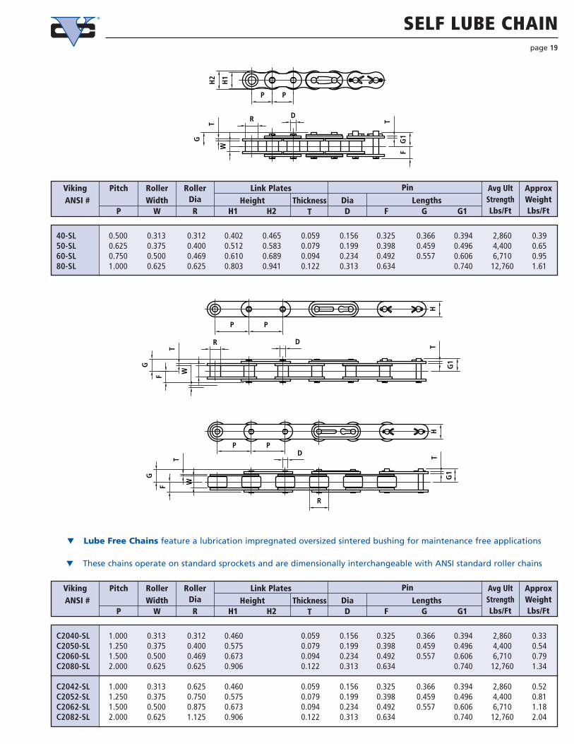
SELF LUBE CHAINpage 19
t Lube Free Chains feature a lubrication impregnated oversized sintered bushing for maintenance free applications
t These chains operate on standard sprockets and are dimensionally interchangeable with ANSI standard roller chains
40-SL 0.500 0.313 0.312 0.402 0.465 0.059 0.156 0.325 0.366 0.394 2,860 0.3950-SL 0.625 0.375 0.400 0.512 0.583 0.079 0.199 0.398 0.459 0.496 4,400 0.6560-SL 0.750 0.500 0.469 0.610 0.689 0.094 0.234 0.492 0.557 0.606 6,710 0.9580-SL 1.000 0.625 0.625 0.803 0.941 0.122 0.313 0.634 0.740 12,760 1.61
VikingANSI #
RollerWidth
RollerDia
Avg UltStrengthLbs/Ft
Approx WeightLbs/Ft
Dia LengthsHeightLink Plates PinPitch
ThicknessP W R H1 H2 T D F G G1
C2040-SL 1.000 0.313 0.312 0.460 0.059 0.156 0.325 0.366 0.394 2,860 0.33C2050-SL 1.250 0.375 0.400 0.575 0.079 0.199 0.398 0.459 0.496 4,400 0.54C2060-SL 1.500 0.500 0.469 0.673 0.094 0.234 0.492 0.557 0.606 6,710 0.79C2080-SL 2.000 0.625 0.625 0.906 0.122 0.313 0.634 0.740 12,760 1.34
C2042-SL 1.000 0.313 0.625 0.460 0.059 0.156 0.325 0.366 0.394 2,860 0.52C2052-SL 1.250 0.375 0.750 0.575 0.079 0.199 0.398 0.459 0.496 4,400 0.81C2062-SL 1.500 0.500 0.875 0.673 0.094 0.234 0.492 0.557 0.606 6,710 1.18C2082-SL 2.000 0.625 1.125 0.906 0.122 0.313 0.634 0.740 12,760 2.04
VikingANSI #
RollerWidth
RollerDia
Avg UltStrengthLbs/Ft
Approx WeightLbs/Ft
Dia LengthsHeightLink Plates PinPitch
ThicknessP W R H1 H2 T D F G G1
D
T
WH
1
P
H2
P
T
G1
F
R
G
G
F
R
T
PP
HT
G1
D
WT
PPD
HT
G1
F
G
R
W

HOLLOW PIN CHAIN
t Hollow Pin Chains are a versatile choice for insertion of attachments or cross-rods into any link of chains
t Hollow Pin Chains are rollerless design (except for C2002 type) and are available in carbon steel, nickel plated and stainless steel
page 20
VikingChain #
WidthBtwn Plates
RollerDia
Approx WeightLbs/Ft
Avg TensileStrength
Lbs/FtDia Bore Dia LengthsHeight
Link Plates PinPitchThickness
P W R H T d F L1 L2
Max AllowLoad
Lbs/Ft
C2042-HP 1.000 0.313 0.625 0.472 0.059 0.222 0.157 0.315 0.374 400 2,500 0.53C2052-HP 1.250 0.376 0.750 0.591 0.079 0.284 0.202 0.400 0.451 700 4,400 0.80C2062-HP 1.500 0.500 0.875 0.709 0.094 0.327 0.236 0.500 0.563 950 6,050 1.15C2082-HP 2.000 0.625 1.125 0.949 0.126 0.444 0.316 0.640 0.701 1700 11000 2.23
VikingChain #
WidthBtwn Plates
BushingDia
Approx WeightLbs/Ft
Avg TensileStrength
Lbs/FtDia Bore Dia LengthsHeight
Link Plates PinPitchThickness
P W B H T d F L1 L2
Max AllowLoad
Lbs/Ft
C2040-HP 1.000 0.313 0.312 0.472 0.059 0.222 0.157 0.315 0.374 400 2,500 0.30C2050-HP 1.250 0.376 0.400 0.591 0.079 0.284 0.202 0.400 0.451 700 4,400 0.50C2060-HP 1.500 0.500 0.469 0.709 0.094 0.327 0.236 0.500 0.563 950 6,050 0.68C2080-HP 2.000 0.625 0.625 0.949 0.126 0.444 0.316 0.640 0.701 1700 11,000 1.25
VikingChain #
WidthBtwn Plates
BushingDia
Approx WeightLbs/Ft
Avg TensileStrength
Lbs/FtDia Bore Dia LengthsHeight
Link Plates PinPitchThickness
P W B H T d F L1 L2
Max AllowLoad
Lbs/Ft
40-HP 0.500 0.313 0.312 0.472 0.059 0.222 0.157 0.315 0.374 400 2,500 0.3450-HP 0.625 0.376 0.400 0.591 0.079 0.284 0.202 0.400 0.451 700 4,400 0.5660-HP 0.750 0.500 0.469 0.709 0.094 0.327 0.236 0.500 0.563 950 6,050 0.8280-HP 1.000 0.625 0.625 0.949 0.126 0.444 0.316 0.640 0.701 1700 11,000 1.45
P
d d R FB F
P P P
H HW
TTTW
TW
H
L2
d B
P P
F
L1
L2L1 L1
L2
C2000 TYPE (C2040HP - C2080HP) C2002 TYPE (C2042HP - C2082HP)
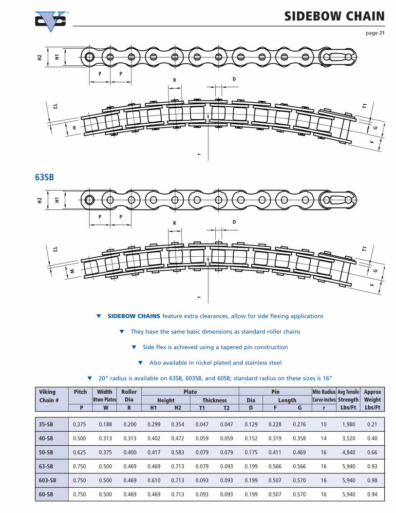
SIDEBOW CHAINpage 21
D
H1
H2
w
T2
RPP
GF
T1
DP P
R
W
T2
H2 H1
T1F
G
rr
35-SB 0.375 0.188 0.200 0.299 0.354 0.047 0.047 0.129 0.228 0.276 10 1,980 0.21
40-SB 0.500 0.313 0.313 0.402 0.472 0.059 0.059 0.152 0.319 0.358 14 3,520 0.40
50-SB 0.625 0.375 0.400 0.417 0.583 0.079 0.079 0.175 0.411 0.469 16 4,840 0.66
63-SB 0.750 0.500 0.469 0.469 0.713 0.079 0.093 0.199 0.566 0.566 16 5,940 0.93
603-SB 0.750 0.500 0.469 0.610 0.713 0.093 0.093 0.199 0.507 0.570 16 5,940 0.98
60-SB 0.750 0.500 0.469 0.469 0.713 0.093 0.093 0.199 0.507 0.570 16 5,940 0.94
VikingChain #
WidthBtwn Plates
RollerDia
Min RadiusCurve-Inches
Avg TensileStrengthLbs/Ft
ApproxWeightLbs/Ft
Dia LengthHeightPlate PinPitch
ThicknessP W R H1 H2 T2T1 D F G r
t SIDEBOW CHAINS feature extra clearances, allow for side flexing applications
t They have the same basic dimensions as standard roller chains
t Side flex is achieved using a tapered pin construction
t Also available in nickel plated and stainless steel
t 20” radius is available on 63SB, 603SB, and 60SB; standard radius on these sizes is 16”
63SB

T2
W
T
W
DR
T
WH
2
H1
T
F
C
CC
FF
DR
R D
TT1P P
G
G G1
G1
G1
G
BRITISH STANDARD CHAIN
t British Standard Chains are slightly different in dimensions to standard roller chains and are also called metric chains. t These chains are often seen in equipment manufactured in Europe
or specified on machinery manufactured for European marketplace.
page 22
VikingChain #
WidthBtwn Plates
RollerDia
TransversePitch
Avg TensileStrength
Lbs/Ft
ApproxWeightLbs/Ft
Dia LengthHeightLink Plates PinPitch
ThicknessP W R H1 H2 T D F G G1
05B 0.315 0.118 0.197 0.276 0.276 0.030 0.091 0.152 0.189 - - 1166 0.1105B-2 0.262 0.301 - 0.222 2112 0.20
06B 0.375 0.225 0.250 0.319 0.319 0.039 0.129 0.240 0.291 - - 2310 0.2606B-2 0.441 0.484 - 0.403 4180 0.5006B-3 0.642 0.685 0.701 0.403 5940 0.73
08B 0.500 0.305 0.335 0.402 0.465 0.059 0.173 0.323 0.374 0.374 - 4246 0.4408B-2 0.602 0.657 0.548 7920 0.8708B-3 0.874 0.925 0.548 11880 1.29
10B 0.625 0.380 0.400 0.512 0.575 0.065 0.199 0.378 0.437 - - 5940 0.6210B-2 0.705 0.764 - 0.653 11440 1.1310B-3 1.031 1.083 1.110 0.653 17270 1.76
12B 0.750 0.460 0.475 0.630 0.630 0.071 0.225 0.437 0.496 - - 7480 0.8312B-2 0.819 0.882 - 0.766 14960 1.5312B-3 1.205 1.256 1.280 0.766 22440 2.38
16B 1.000 0.670 0.625 0.819 0.819 0.157 0.326 0.697 0.758 0.795 - 17600 1.7816B-2 1.324 1.384 1.424 1.255 35200 3.5216B-3 1.952 2.013 2.052 1.255 52800 5.27
20B 1.250 0.770 0.750 1.024 1.024 0.173 0.401 0.807 - 0.925 - 26400 2.5820B-2 1.525 - 1.643 1.435 52,800 5.1320B-3 2.242 - 2.360 1.435 79,200 7.68
24B 1.500 1.000 1.000 1.299 1.299 0.236 0.576 1.049 - 1.274 - 39600 5.1024B-2 2.001 - 2.226 1.904 77000 9.9224B-3 2.953 - 3.178 1.904 115500 14.68
28B 1.750 1.220 1.100 1.457 1.457 0.291 0.626 1.279 - 1.495 - 46200 6.0728B-2 2.451 - 2.667 2.345 90200 11.4828B-3 3.624 - 3.840 2.345 132000 17.17
32B 2.000 1.220 1.150 1.654 1.654 0.279 0.701 1.287 - 1.503 - 58300 7.1332B-2 2.439 - 2.656 2.305 111100 13.9832B-3 3.592 - 3.808 2.305 167200 21.17
40B 2.500 1.500 1.550 2.083 2.083 0.315 0.901 1.583 - 1.862 - 87120 10.9040B-2 3.006 - 3.285 2.846 167200 21.3640B-3 4.429 - 4.709 2.846 246400 32.28
48B 3.000 1.800 1.900 2.500 2.500 0.390 1.151 1.945 - 2.224 - 136840 16.8048B-2 3.740 - 4.020 3.591 259600 33.4148B-3 5.535 - 5.815 3.591 389400 50.34

GENERAL PRECAUTIONS
t Use factory supplied lengths - do not assemblechains from individual components
t Do not replace individual worn parts
t No leaf chain should be plated or painted
t No welding is allowed on any leaf chain or weldsplatter allowed to come into contact with chains
t Leaf chains are used on sheaves not sprockets.These sheaves should be inspected on a regular basisfor worn flanges
t In order to provide good service life, lubricationmust be provided on a regular basis
t Whatever lubrication, SAE 30 is standard. Thelubrication must penetrate the chain and reach thejoints
t ANSI recommendation on lubrication, checking forwear, and installation guides are available from ourservice centers
LEAF CHAIN GENERAL INFOpage 23
2 X 2
4 X 4 4 X 6 6 X 6
2 X 3 3 X 4
LACING COMBINATIONS
t Leaf Chains consist of interlacing plates and riveted pins. Typical lacing patterns are shown above
t Chains are usually supplied in strands and be supplied ending with inside ends (male ends) or outside ends (female ends).Strands ordered with even pitches will be supplied with one ending in inside links and one end with male ends
t The type of cleavis on machinery will determine the configuration of ends is required. When "female ends" are required,the clevis manufacturer should supply the connecting pins. When "male ends" are ordered, drive fit connecting pins, either
riveted or cottered style, are recommended ordered at the same time

LIGHT DUTY LEAF CHAINSpage 24
VikingChain #
Pitch Approx WeightLbs/Ft
Avg UltStrength
Lbs/Ft
Height LengthLacing Thickness Diameter
P H DT L
AL422 2x2 0.500 0.402 0.059 0.156 0.317 3,960 0.24AL444 4x4 0.565 7,920 0.46AL466 6x6 0.815 11,880 0.71
AL522 2x2 0.625 0.512 0.079 0.200 0.417 6,820 0.40AL544 4x4 0.748 13,640 0.77AL566 6x6 1.079 20,460 1.14AL588 8x8 1.409 27,280 1.52
AL622 2x2 0.750 0.610 0.093 0.234 0.488 9,900 0.53AL644 4x4 0.878 19,800 1.01AL666 6x6 1.270 27,000 1.55AL688 8x8 1.661 39,600 2.07
AL822 2x2 1.000 0.803 0.122 0.313 0.616 17,160 0.91AL844 4x4 1.120 34,320 2.69AL866 6x6 1.624 51,480 3.60AL888 8x8 2.128 68,640 4.50
AL1022 2x2 1.250 0.976 0.154 0.375 0.819 26,400 1.59AL1044 4x4 1.465 52,800 3.11AL1066 6x6 2.110 79,200 4.64AL1088 8x8 2.756 105,600 6.28
AL1222 2x2 1.500 1.181 0.185 0.437 0.969 35,200 2.28AL1244 4x4 1.740 70,400 4.47AL1266 6x6 2.512 105,600 6.66
t AL- Series Leaf Chains are widely used in light duty applications and where chains receive only static loads
t These chains were removed from B29.8 ANSI STANDARDS
t BL Series Leaf Chains should be considered in any new applications
t See page 23 for special notes on Leaf Chain
2 X 2
4 X 4 4 X 6 6 X 6
2 X 3 3 X 4
LACING COMBINATIONS
H
PP
L
DT

HEAVY DUTY LEAF CHAINSpage 25
VikingChain #
Lacing Approx WeightLbs/Ft
Avg UltStrength
Lbs/Ft
Pitch Diameter LengthISO/DIN Height Thickness
HP T D L
BL423 LH0823 2 X 3 0.500 0.472 0.079 0.199 0.496 6,600 0.52BL434 LH0834 3 X 4 0.661 9,900 0.72BL444 LH0844 4 X 4 0.744 13,200 0.80BL446 LH0846 4 X 6 0.909 13,200 0.99BL466 LH0866 6 X 6 1.071 19,800 1.21
BL523 LH1023 2 X 3 0.625 0.585 0.095 0.234 0.598 9,900 0.76BL534 LH1034 3 X 4 0.791 14,960 1.05BL544 LH1044 4 X 4 0.892 19,800 1.19BL546 LH1046 4 X 6 1.083 19,800 1.49BL566 LH1066 6 X 6 1.280 29,700 1.84
BL623 LH1223 2 X 3 0.750 0.705 0.124 0.313 0.762 15,400 1.22BL634 LH1234 3 X 4 1.022 23,100 1.69BL644 LH1244 4 X 4 1.161 30,800 1.92BL646 LH1246 4 X 6 1.417 30,800 2.39BL666 LH1266 6 X 6 1.667 46,200 2.86
- BL823 LH1623 2 X 3 1.000 0.944 0.154 0.375 0.994 26,400 2.11BL834 LH1634 3 X 4 1.320 39,600 2.93BL844 LH1644 4 X 4 1.483 52,800 3.34BL846 LH1646 4 X 6 1.809 52,800 4.16BL866 LH1666 6 X 6 2.135 79,200 5.03
BL1023 LH2023 2 X 3 1.250 1.185 0.185 0.437 1.169 35,200 2.58BL1034 LH2034 3 X 4 1.555 52,800 3.92BL1044 LH2044 4 X 4 1.748 70,400 4.83BL1046 LH2046 4 X 6 2.134 70,400 5.53BL1066 LH2066 6 X 6 2.520 105,600 7.13
BL1223 LH2423 2 X 3 1.500 1.378 0.220 0.500 1.372 45,100 4.39BL1234 LH2434 3 X 4 1.831 67,650 6.10BL1244 LH2444 4 X 4 2.059 90,200 6.97BL1246 LH2446 4 X 6 2.518 90,200 8.05BL1266 LH2466 6 X 6 2.976 135,300 9.78
BL1423 LH2823 2 X 3 1.750 1.66 0.252 0.563 1.496 52,700 5.87BL1434 LH2834 3 X 4 2.031 94,800 8.19BL1444 LH2844 4 X 4 2.283 105,400 9.35BL1446 LH2846 4 X 6 2.803 105,400 11.66BL1466 LH2866 6 X 6 3.346 158,000 13.99
BL1623 LH3223 2 X 3 2.000 1.90 0.283 0.687 1.693 78,710 7.50BL1634 LH3234 3 X 4 2.291 124,300 10.45BL1644 LH3244 4 X 4 2.575 157,400 11.92BL1646 LH3246 4 X 6 3.157 157,400 14.86BL1666 LH3266 6 X 6 3.764 236,100 17.81
2 X 2
4 X 4 4 X 6 6 X 6
2 X 3 3 X 4
t BL Series Leaf Chains conform to ASME B29.8 Standardst Feature links plates heavier than AL Series Chains of the same pitch.
LACING COMBINATIONSL
D
H
PP
T

ATTACHMENT CHAINS SPECIFICATIONSpage 26
A-1 K-1
D-1
SA-1 SK-1 D-3
A-1 Attachment tab isbent on one side of thechain - one hole
K-1 Attachment tab isbent both sides of chain- one hole
D-1 Attachment -extended pin on oneside of pin link
SA-1 Attachment tab isstraight up on one sideof the chain - one hole
SK-1 Attachment tab isstraight up on both sidesof the chain - one hole
D-3 Attachment -extended pin on eachside of pin link
SOME APPLICATIONS
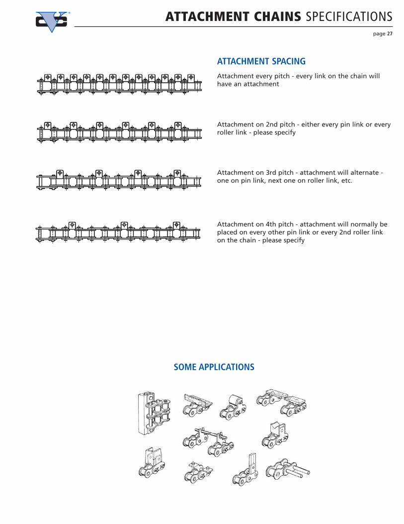
ATTACHMENT CHAINS SPECIFICATIONSpage 27
ATTACHMENT SPACING
SOME APPLICATIONS
Attachment every pitch - every link on the chain willhave an attachment
Attachment on 2nd pitch - either every pin link or everyroller link - please specify
Attachment on 3rd pitch - attachment will alternate -one on pin link, next one on roller link, etc.
Attachment on 4th pitch - attachment will normally beplaced on every other pin link or every 2nd roller linkon the chain - please specify

STANDARD ROLLER CHAIN ATTACHMENTS
VikingANSI # Width
Roller Plate PinDia SA-1 SK-1
Average UltimateStrength
Lbs/Ft
Hole Dia A-1 K-1Height Thickness DiameterStandard AttachmentsPitch
Width ofAtt Plt
P W R H T D N O C X Y S Z
page 28
VikingANSI #
RollerPitchExt Pin Lgthmid chain toend of ext pin
Ext Pin Lgthside plate toend of ext pin
PinDiameter
Average UltimateStrength
Lbs/Ft
HeightDiameterWidth ThicknessPlate Extended Pitch Attachments
LDHDT2T1H2H1RWP
35 0.375 0.188 0.200 0.299 0.354 0.047 0.047 0.141 0.375 0.572 2,310
40 0.500 0.313 0.312 0.402 0.465 0.059 0.059 0.156 0.375 0.658 4,070
50 0.625 0.375 0.400 0.512 0.583 0.079 0.079 0.199 0.469 0.825 6,820
60 0.750 0.500 0.469 0.610 0.689 0.094 0.094 0.234 0.562 1.004 9,680
80 1.000 0.625 0.625 0.803 0.941 0.122 0.122 0.313 0.750 1.318 17,160
100 1.250 0.750 0.750 0.976 1.185 0.154 0.154 0.375 0.938 1.647 26,007
120 1.500 1.000 0.875 1.181 1.378 0.185 0.185 0.437 1.126 2.018 34,100
160 2.000 1.250 1.125 1.630 1.890 0.252 0.252 0.562 1.500 2.652 60,500
35 0.375 0.188 0.200 0.354 0.047 0.141 0.311 .106 - .134 0.250 0.374 0.563 0.374 0.573 2,310
40 0.500 0.313 0.312 0.465 0.059 0.156 0.374 0.142 0.315 0.500 0.701 0.500 0.685 4,070
50 0.625 0.375 0.400 0.583 0.079 0.199 0.500 0.205 0.406 0.626 0.921 0.626 0.907 6,820
60 0.750 0.500 0.469 0.689 0.094 0.234 0.626 0.205 0.469 0.750 1.110 0.720 1.057 9,680
80 1.000 0.625 0.625 0.941 0.122 0.313 0.752 0.268 0.626 1.000 1.441 0.969 1.396 17,160
100 1.250 0.750 0.750 1.185 0.154 0.375 1.000 0.343 0.780 1.250 1.768 1.252 1.732 26,007
120 1.500 1.000 0.875 1.378 0.185 0.437 1.126 0.390 0.906 1.500 2.197 1.437 2.081 34,100
160 2.000 1.250 1.125 1.890 0.252 0.562 1.500 0.520 1.252 2.000 2.827 2.000 2.760 60,500
Y
P
N
H
C
O
P
N
P
W
WT
HT
D
R
Z S
O
P
D
R
X
A-1
SA-1
Y
P
H
P
N
C
O
W
P
R
TW
H
P
NZ S
O
T
R
D
D
X
K-1
SK-1
R
H2
H1
T2
W
PP
LDH
D
TI
R
P
H2
H1
P
D
W
H2
L
T1
DH
D-1
D-3

WIDE CONTOUR ATTACHMENTSpage 29
35 0.375 0.188 0.200 0.354 0.047 0.141 0.374 0.673 0.130 0.250 0.374 0.563 0.374 0.543 2,310
40 0.500 0.313 0.312 0.465 0.059 0.156 0.374 0.902 0.130 0.177 0.315 0.500 0.701 0.500 0.685 4,070
50 0.625 0.375 0.400 0.583 0.079 0.199 0.469 1.130 0.201 0.217 0.406 0.626 0.921 0.626 0.907 6,820
60 0.750 0.500 0.469 0.689 0.094 0.234 0.563 1.362 0.202 0.260 0.469 0.750 1.110 0.720 1.057 9,680
80 1.000 0.625 0.625 0.941 0.122 0.313 0.752 1.799 0.268 0.354 0.626 1.000 1.441 0.969 1.396 17,160
VikingChain
#Width
Roller Plate Pin
Dia DiaWSA-2 WSK-2
AverageUltimateStrengthLbs/Ft
HoleDia(WA WK)
HoleDia(WSA WSK) WA-2 WK-2
Height Thickness Dist betweenholes inAtt Plate
Wide Contour Attachments - Two Hole AttachmentsPitchWidth ofAtt Plt
P W R H T D M N O O XC Y S Z
W
N
P
H
P
C
ON
P
W
T
HT
D
R
T
P
O
D
R
T
W
N
P
H
P
O
C
T
N
P
T
H
P
T
O
T
R
T
D
R
SZ
X Y
X Y
Z S
D
N
P
H
P
C
N
P
W W
T
HT
D
R
T
P
D
R
T
Y
P
H
PC
W
N
P
W
T
H
PT
D
Z
T
R
T
D
S S
MO
MO
X
MO
X
O
Z
Y R
M
N
WA-1
WA-2 WK-2 WSA-2 WSK-2
WK-1 WSA-1 WSK-1
35 0.375 0.188 0.200 0.354 0.047 0.141 0.673 0.130 0.250 0.374 0.563 0.374 0.543 2,310
40 0.500 0.313 0.312 0.465 0.059 0.156 0.902 0.130 0.177 0.315 0.500 0.701 0.500 0.685 4,070
50 0.625 0.375 0.400 0.583 0.079 0.199 1.130 0.201 0.217 0.406 0.626 0.921 0.626 0.907 6,820
60 0.750 0.500 0.469 0.689 0.094 0.234 1.362 0.202 0.260 0.469 0.750 1.110 0.720 1.057 9,680
80 1.000 0.625 0.625 0.941 0.122 0.313 1.799 0.268 0.354 0.626 1.000 1.441 0.969 1.396 17,160
VikingChain
#Width
Roller Plate PinDia
WSA-1 WSK-1
AverageUltimateStrengthLbs/Ft
Hole Dia(WA WK)
Hole Dia(WSA WSK) WA-1 WK-1
Height Thickness DiameterWide Contour Attachments - One Hole AttachmentsPitch
Width ofAtt Plt
P W R H T D N O O XC Y S Z

SS MEGA ATTACHMENT CHAIN SPECIFICATIONSpage 30
t Roller chain sizes 40through 80, single and double
t Double pitch chain C2040 through C2080
t All standardattachments
t Patented designprovides twice thetensile strength ofstandard stainless steel chains
t Patented designprovides;
t twice the tensilestrength of standard stainless steelchains
t twice the allowableload
t 50% better elongation results
t pin protection from debris
t Uses standard sprockets
t Reduces maintenance
MEGA CHAIN DETAIL
MEGA CHAIN
MEGA ATTACHMENT
Inner Plate Dust Prevention Outer Plate

SS MEGA CHAIN STANDARD ATTACHMENTSpage 31
40SS 0.500 0.313 0.312 0.472 0.059 0.156 0.374 0.142 0.315 0.500 0.701 0.500 0.685 154 3,960
50SS 0.625 0.375 0.400 0.591 0.079 0.199 0.500 0.205 0.406 0.626 0.921 0.626 0.907 264 7,040
60SS 0.750 0.500 0.469 0.713 0.093 0.234 0.625 0.205 0.469 0.750 1.110 0.720 1.057 363 9,680
80SS 1.000 0.625 0.625 0.945 0.118 0.313 0.752 0.268 0.626 1.000 1.441 0.969 1.396 638 15,840
VikingMegaChain
#
Width
Roller Plate PinDia
SA-1 SK-1
AverageUltimateStrength
Lbs/Ft
MaxAllowLoad
Lbs/Ft
HoleDia A-1 K-1
Height Thickness DiameterStandard AttachmentsPitch
Width ofAtt Plt
P W R H T D N O C YX S Z
4
M
E
W
H
SS0
GA
S04
S
AE
M
G
S04
S
M
E GA
S4S0
M
GE A
C
S
P
4
MH
S0 S
GE A
SS4
0
GE
M
A
S04
S
E
M
AG
40 S
M
E AG
CY
W
T
R
N O
D
X
ON
W
T
R
Y
D
X
A-1
K-1

SS MEGA WIDE CONTOUR ATTACHMENTSpage 32
40SS 0.500 0.500 0.313 0.312 0.472 0.059 0.968 0.177 0.315 0.500 0.701 0.500 0.685 154 3,960
50SS 0.625 0.625 0.375 0.400 0.591 0.079 1.213 0.217 0.406 0.626 0.921 0.626 0.907 264 7,040
60SS 0.750 0.750 0.500 0.469 0.713 0.093 1.457 0.260 0.469 0.750 1.110 0.720 1.057 363 9,680
80SS 1.000 1.000 0.625 0.625 0.945 0.118 1.949 0.354 0.626 1.000 1.441 0.969 1.396 638 15,840
VikingMegaChain
#
Width
Roller Plate PinDia
WSA-1 WSK-1
AverageUltimateStrength
Lbs/Ft
MaxAllowLoadLbs/Ft
HoleDia WA-1 WK-1
Height Thickness DiameterWide Contour One Hole AttachmentsPitch
Width ofAtt Plt
P W R H T D N O C YX S Z
40SS 0.500 0.500 0.313 0.312 0.472 0.059 0.968 0.500 0.177 0.315 0.500 0.701 0.500 0.685 154 3,960
50SS 0.625 0.625 0.375 0.400 0.591 0.079 1.213 0.625 0.217 0.406 0.626 0.921 0.626 0.907 264 7,040
60SS 0.750 0.750 0.500 0.469 0.713 0.093 1.457 0.750 0.260 0.469 0.750 1.110 0.720 1.057 363 9,680
80SS 1.000 1.000 0.625 0.625 0.945 0.118 1.949 1.000 0.354 0.626 1.000 1.441 0.969 1.396 638 15,840
VikingMegaChain
#
Width
Roller Plate PinDia Wide Contour Plates
WSA-2 SK-2
AverageUltimateStrength
Lbs/Ft
MaxAllowLoadLbs/Ft
HoleDia
Wide Contour PlatesWA-2 WK-2
Height Thickness DiameterWide Contour Two Hole AttachmentsPitch
Width ofAtt Plt
P W R H T D N M O C YX S Z
4
ME
P
H
SS0
GA
S04
S
AE
M
G
S04
S
M
E GA
S4S0
M
GE A
A
P
H
S04
S
AE
M
G
S40 S
M
E AG
S4S0
M
GE A
04
S
E
M
G
S
W
T
R
NO
D
X Y
NO
R
T
W
C
YX
D
WA-1
WK-1

DOUBLE PITCH CONVEYOR ATTACHMENTSpage 33
C2040 1.00 0.313 0.312 0.156 0.752 0.142 0.201 0.358 0.500 0.695 0.500 0.760 0.437 0.780 0.156 0.375 0.658 4,100 C2050 1.25 0.375 0.400 0.200 0.937 0.201 0.268 0.437 0.626 0.864 0.626 0.951 0.561 0.949 0.200 0.469 0.825 6,800 C2060H 1.50 0.500 0.469 0.234 1.126 0.201 0.343 0.579 0.844 1.129 0.844 1.258 0.689 1.242 0.234 0.562 1.066 11,700 C2080H 2.00 0.625 0.625 0.312 1.500 0.268 0.406 0.752 1.094 1.438 1.094 1.602 0.874 1.594 0.312 0.750 1.385 20,300
C2042 1.00 0.313 0.625 0.156 0.752 0.142 0.201 0.358 0.500 0.695 0.500 0.760 0.437 0.780 0.156 0.375 0.658 4,100 C2052 1.25 0.375 0.750 0.200 0.937 0.201 0.268 0.437 0.626 0.864 0.626 0.951 0.561 0.949 0.200 0.469 0.825 6,800 C2062H 1.50 0.500 0.875 0.234 1.126 0.201 0.343 0.579 0.844 1.129 0.844 1.258 0.689 1.242 0.234 0.562 1.066 11,700C2082H 2.00 0.625 1.125 0.312 1.500 0.268 0.406 0.752 1.094 1.438 1.094 1.602 0.874 1.594 0.312 0.750 1.385 20,300
VikingChain
#
Width RollerDia
PinDia
D-3D-1
AverageUltimateStrengthLbs/Ft
A-1 K-I SA-1 SK-1
AttPlateWidth
AttHole DiaA-1 K-1
AttHole DiaSA-1 SK-1
D AttPin Dia
Attachments SpecificationsPitch
P W R D N O O C X Y X1 SY1 Z DHD L
A-1
SA-1
K-1
SK-1
NO
O
NO
R
P
P P
N
R R
D
P
R
DD
Y1
X1
O
N
PP
S
Z
S
Z
D
WW
P P
CC
Y1 X1
CW
X
Y
W
X Y
D
P
R
W
DH
P
L L
P
D
P
R
W
DH
D-1 D-3
Refer to page 12 for H & T Link Plate Dimensions

DOUBLE PITCH CONVEYOR ATTACHMENTSpage 34
C2040 1.00 0.313 0.312 0.156 0.752 0.142 0.374 0.358 0.500 0.695 0.500 0.760 0.538 0.780 4,100 C2050 1.25 0.375 0.400 0.200 0.937 0.201 0.469 0.437 0.626 0.864 0.626 0.951 0.626 0.949 6,800 C2060H 1.50 0.500 0.469 0.234 1.126 0.201 0.563 0.579 0.844 1.129 0.844 1.258 0.752 1.242 11,700 C2080H 2.00 0.625 0.625 0.312 1.500 0.268 0.752 0.752 1.094 1.438 1.094 1.602 1.000 1.594 20,300
C2042 1.00 0.313 0.625 0.156 0.752 0.142 0.374 0.358 0.500 0.695 0.500 0.76 0.538 0.780 4,100 C2052 1.25 0.375 0.750 0.200 0.937 0.201 0.469 0.437 0.626 0.864 0.626 0.951 0.626 0.949 6,800 C2062H 1.50 0.500 0.875 0.234 1.126 0.201 0.563 0.579 0.844 1.129 0.844 1.258 0.752 1.242 11,700 C2082H 2.00 0.625 1.125 0.312 1.500 0.268 0.752 0.752 1.094 1.438 1.094 1.602 1.000 1.594 20,300
VikingMegaChain
#SA-2 SK-2
AverageUltimateStrength
Lbs/Ft
A-2 K-2
Attachment SpecificationsPitch Width RollerDia
PinDia
AttPlateWidth
AttHoleDia
DistBetweenAtt Holes
P W R D N O M C X X1 Y1Y S Z
TH
P
H
O
D
T
R
P
N
S
M
T
R
M
N
PP
O
T
W W
Z Z
S
D
Y1
X1
D
P
H
C
P
R
T
O
YX
T
M
N
P
H
P
OW
YX
T
W
R
Y1
D
X1
T
N
M
C
A-2 K-2
SA-2 SK-2
Refer to page 12 for H & T Link Plate Dimensions

SPECIAL MARKET CHAINSpage 35
TW
PP
R
R1
W1
H
D
GF
.575
.750
1.20
5
1.25
.497
1.23
6
1.54
3
.080
.200
TRIPLE SPEED CHAINS
t Conveyor Chains with a blackplastic (POM 90) large roller which
inhibits static electricity, and small gray(nylon 66 ) material roller allows for
material to be transported at 2.5 timesthe speed of the base chain
t Base chain available in carbonsteel, coated with zinc plated inside
plates and nickel plated outer plates,as well as stainless steel
Contact Viking service centers for
special requirements
VikingChain #
Width Approx WeightLbs/Ft
Avg UltStrength
Lbs/FtHeight Thickness Diameter LengthsDiameterHeight
Roller Plate PinPitch
P W W1 R R1 H T D F G
C2050-JDS 1.25 1.08 0.496 1.205 0.750 0.575 0.080 0.200 0.756 0.815 6600 0.94
C2060H-JDS 1.50 1.31 0.610 1.437 0.886 0.673 0.122 0.234 0.951 1.018 9240 1.34
t Snap covers drawn below, also available from the factory
C2050 - JDS - CVR

SPECIAL MARKET CHAINSpage 36
CITRUS / AGRICULTURAL CHAINS
t Viking Citrus, sometimes called agricultural chains, are used to convey product on bucket elevatorst They are available with same length of pin and two separate pin diameters, 1/2" and 916"
t Also available in plated and stainless steel
Consult Viking service centers for special requirements
DOUBLE FLEX CHAINS
t Transfer conveyor chains used in many applications featuring induction hardened pins, thru hardened sidebars and inner links for extended wear life
VikingChain #
Approx WeightLbs/Ft
Avg TensileStrength
Lbs/FtDia LengthHeight
Link Plates PinTypeThickness
RollerWidth
RollerDia
Pitch
P W R H T D D1 D2 M DH L
C2060H 1/2" 1.500 0.500 0.469 0.670 0.125 0.234 0.310 0.343 0.500 1.625 2.720 1.20 99009/16" 0.563
VikingChain #
Chain WidthPitch Avg UltTensile
StrengthLbs/Ft
MaximumAllowable
LoadLbs
AverageWeight
Lbs/Ft
Overall InsideInnerLink
OuterLink
Thickness Height DiameterLink Plate Pin
RadiusMaximum
RDHTWL
DF3500 3.000" 2.5000" 1.500 0.625 0.250 1.25 0.562 20" 3.3 4000 48000
DH
D2
D1
P
L T
R
HW
P
M
D
MAX. FLEX RADIUSR20.000"
H
W
2.500” 3.000”
L
D
T
A

TRIMMER CHAINSpage 37
A
EH
C
H
A
C
E
VikingChain #
Links/Ft Approx WeightLbs/Ft
Pitch OverallWidth
InsideWidth
Inner SB Thickness
Outer SB Thickness
PinDiameter
Roller Diameter
RooftopHeight
Rooftop Width
BA C F F1 G H M
SidebarHeight
E N
81X 2.609 4.6 2.6 1.937 1.062 .156 .156 .4375 .9062 1.125 - -
81X H 2.609 4.6 3.9 2.325 1.062 .156 .218 .4375 .9062 1.250 - -
81X XHD 2.609 4.6 4.6 2.625 1.062 .156 .312 .4375 .9062 1.250 - -
81X ROOFTOP 2.609 4.6 6.0 2.000 1.062 .156 .156 .4375 .9062 - 1.500 1.8125
*3939G4 8.000 1.5 1.62 1.937 1.062 .156 .156 .4375 .9062 1.125 - -
VikingChain #
Links/Ft RooftopHeight
HeightApprox WeightLbs/Ft
Pin Diameter
ThicknessPitch Width Inner LinkWidth
AP B C D E H
H78 2.609 4.6 4.3 3.250 - .500 - - -
H78 A/B 2.609 4.6 5.6/6.2 3.250 - .500 - - 1.690
H130/138 4.000 3 5.3/5.9 3.250 - .500 - - 1.690
C55 1.630 7.4 2.0 2.000 1.250 .375 .218 .750 -
C188 2.609 4.6 3.5 2.562 1.562 .500 .250 1.125 -
C131 3.075 3.9 6.7 3.250 3.437 .625 .375 1.500 -
C102B 4.000 3 6.4 4.312 2.875 .625 .375 1.500 -
C55A/B 1.630 7.4 2.5 2.000 1.218 .375 .218 .718 1.625
BA
D
P
C
E
C55, C102B, C131, C188
H78BH138C55B
H78AH130C55A
* 4 holes per side bar 9/32 diameter @ 1.5” and 4” centers - other configurations are also available
A
C H G B
AF
C B
HG
A
CH G
B
M
A
N
B
A
CH G
F F
F
EE
F1
F1
E
F1
F1
E
81X
81X HH3939G4
81XH81X ROOFTOP

CHAIN TOOLSpage 38
CHAIN PULLER
The Chain Puller is an additional tool which providesa fast and easy method for endless chain assembly.The two jaws are hooked into the ends of the chain,and the hand screw is turned until the connectinglink glides into position.
Model Chain Size
No. 35 35 - 60
No. 60 60 - 100
No. 80 80 - 240
CHAIN DETACHER
The Chain Detacher is a lightweight hand tool thatquickly disassembles roller chain without the need ofa hammer, punch or vise. In short, “one tool does allthe work”. There are three models fro use with ANSIStandard Chains. sizes No. 35 through No. 100.
Model Chain Size
No. 50 35 - 50
No. 60 35 - 60
No. 100 60 - 100
STRAIGHT PUNCH TYPE CHAIN CUTTER
The Straight punch type Chain Cutter provides higherefficiency for quick disassembly of chains comparedwith the conventional chain cutter.
Model Chain Size
No. 25 25
No. 35 - 40 35 - 40
No. 50 50
No. 60 60
No. 80 80
No. 100 100

CHAIN DRIVE SELECTIONpage 39
CHAIN DRIVE SELECTION
Chains can be selected by two methods;1. General Selection2. Slow-speed Selection
1: General SelectionThe following information is essential in order to select the appropriate chain and sprocket for rollerchain transmission
Power to be transmitted = kW
Speed of driving shaft and driven shaft perminute
Speed ratio refers to the ratio of the speed of thedriving shaft to the speed of the driven shaft. The speed ratio of chains can range up to 7:1 undernormal operating conditions.
The take up angle between the smaller sprocket andthe chain should be at least 120 degrees to obtainsmooth transmission.
1) Adjust power to be transmitted (kW)
The actual power to be transmitted is affected by theload of the machine and power source used. Adjustments must be made according to ServiceFactor shown on Table 1. The power to betransmitted (kW) is multiplied by the correspondingservice factor to obtain the design kW value.
2) Determine roller chain and number of teeth of thesmaller sprocket.
Use the Quick Selection Table (Table V) and select anappropriate chain and the number of teeth for thesmall sprocket by referring to the number ofrevolutions of the high speed shaft (i.e., the driving shaft when the speed is reduced; the driven shaftwhen the speed is increased) and the design kW.
If the capacity of simplex chain is insufficient, select aMultiplex chain. In this case, use the following table todetermine the multi-strand factor.
Table II Multi-Strand Factor
No. of Roller Chain Strand Multi-Strand Factor2 1.73 2.54 3.35 3.96 4.6
3) Determine the number of teeth of the large sprocket
After the number of teeth of the small sprocket isdetermined, multiply it by the speed ratio to determinethe number of teeth of the large sprocket. Therecommended maximum number of teeth is 114 or less.
Center distance between driving shaft and drivenshaft Sprockets can be separated at any distance aslong as the teeth do not touch. Optimum distance is30 to 50 times the pitch of chain used.
Construction or Mining machines, Presses,Vibration machines, General machines with
reverse or impact load
Centrifugal compressors, Conveyors with moderate load fluctuation, Dryers, General work machines
Agitators, Centrifugal Blowers, Textile machines,General machines with small load fluctuation
Smooth
Type of Impact Examples of Machines Type of Impact PowerInternal Combustion Engine
Electric motor or turbine
With hydraulic drive
Withouthydraulic drive
1.0 1.0 1.2
1.3 1.2 1.4
1.5 1.4 1.7
Moderate
Heavy
Table 1: Service Factor

CHAIN DRIVE SELECTIONpage 40
4) Calculate Chain Length
The number of pitches (length of chain) can beobtained by the following formula (Note: Raise thevalue to a unit to make it an integer.)
Lp = N1 + N2 + 2 Cp + { (N2 - N1) } / 2 }2
L: Number of pitches chainN 1: Number of teeth of small sprocketN 2: Number of teeth of large sprocketC: Center distance of two sprockets/Chain Pitch
If the number of pitches is already given, the center distance between the sprockets can be obtained by the following formula:
Cp = 1 { Lp - N1 + N2 + (Lp - N1 + N2) 2 - 2 (N2 -N1)2 }4 2 ∏2 2
2. Slow Speed SelectionThis is one of the economical selection methods basedon fatigue strength of chain for conditions where (i) the operational speed of chain is 50 meters / minute
or less, and (ii) there is no concern of wear elongation and shock
fracture of rollers and bushings. However, a chainselected by this method may be subject to severeconditions and, thus, special care should be takenon the chain selection. The slow speed selection isnot applicable to the connecting and offset link.
1) Calculate Chain Tension
If the chain tension is unknown, it can be obtained byusing the following formula with kW of the inputpower to be transmitted.
F = 60 x kW (kN)V
F: Chain TensionV: Chain Speed (m/mm)
2) Determine Corrected Chain Tension
Chain tension needs to be corrected as per theconditions of use, in the same way as described inGeneral Selection section. Use Service Factor (Table I )and then Sprocket Tooth Factor (Table III) and SpeedFactor (Table IV) to take into consideration increase oftension caused by vibration, centrifugal force, inertiaforce, etc.
The corrected Chain Tension can be obtained using thefollowing formula:Corrected Chain Tension = Chain Tension x Service Factor x Sprocket Teeth Factor x Speed Factor
Table III: Sprocket Tooth Factor
9 1.085 19 1.02211 1.068 21 1.01413 1.054 23 1.00715 1.042 25 or over 1.00017 1.031
Number ofTeeth on
Small Sprocket
Sprocket Tooth
Sprocket Tooth
Number ofTeeth on
Small Sprocket
Table IV: Speed Factor
3) Determine the Chain
If the maximum allowable tension stated in the tableof each chain dimensions is larger than the correctedchain tension, the chain is selected correctly.
4) Check Chain Speed
The chain speed can be calculated using the formulabelow. If the chain speed exceeds 50m/min., chooseGeneral Selection instead of Slow-speed Selection.
V = P x N1 x r11000
V : Chain Speed (m/min)P : Chain Pitch (mm)N1: Teeth of small sprocketr1: Revolution of Small Sprocket (RPM)
The method for determining the number of teeth oflarge sprocket and calculation of chain length is thesame as those described at General Selection section.
Consult with Viking service center for chain for use on(i) transmission of frequent go & stop, and (2) inversionwith impact load.
1.8
1.6
1.4
1.2
1 2 5 10 20 50 100 200
rpm - Small Sprocket
Spee
d Fa
ctor

QUICK SELECTION GUIDEpage 41
6
Number of chain strands
5 4 3 2 110 20 30 40 50 60 70 100 200 300 500 700 1000 2000 3000 5000 7000 10000
20
40
30
5060 70
200
30050070010001000
1000
700
500
300
200
100
70
50
40
30
20
10
7
5
4
3
2
1
0.7
0.5
0.4
0.3
700
500
300
200
100
70
50
40
30
20
10
7
5
4
3
2
1
0.7
0.5
0.4
0.3
700
500
300
200
100
70
50
40
30
20
10
7
5
4
3
2
1
0.7
0.5
0.4
0.3
0.2
500
300
200
300
200
100
70
50
40
30
20
10
7
5
4
3
2
1
0.7
0.5
0.4
0.3
0.2
0.1
90
9.08.07.06.0
5.0
4.0
3.0
2.0
1.00.90.80.70.60.5
0.4
0.3
0.2
0.1
80
10
240 200
180
160140
120
80
6050
40
35
25
100
100
70
50
40
30
20
10
7
5
4
3
2
1
0.7
0.5
0.4
0.3
0.2
100
R.P.M. - Small Sprocket
How to use this table:
For easy selection of chain and sprocket, check the intersection of revolution per minute (RPM) of design kW(vertical axis) and the small sprocket (horizontal axis).
Example:Assume design kW is 5kW and the RPM of the small sprocket is 100. By taking the intersection point of this design kW value of 5kW and RPM value is 100, one can derive # 80 ANSI chain and a sprocket of 16 Teeth from the chart.

LUBRICATIONpage 42
Method of Lubrication Form of Lubrication
Manual LubricationAim at the space between link plates
and roller links
Lubricate the chain a minimum of once every 8 hours during chain operation, to minimize drying, using a brush or spout can
Drip Lubrication Using a simple case, drop oil and lubricate by
using an oil cup or drip applicator
Chain should normally receive 5-20 drops of oil per minute, depending on chain speed, using a drip lubricator. Oil level should be periodically
checked and fill reservoir as required
Slinger Disk Lubrication Inside an oil leak proof casing, a slinger disk is
attached from the diameter of the sprocket, andsplashes oil to lubricate chains
In this method, the chain operates above the oil level. A disc on one shaftpicks oil up from the sump, and slings it against a collector plate. The oilusually flows through a trough and is applied to the upper edges of the
link plates in the lower strand of the chain. The diameter of the discshould produce rim speeds between 600 ft/min and 8000 ft/min. Lowerspeeds will not be effective and higher speeds will produce oil foam andcause over heating. Oil temperature should not exceed 180 degrees F
A short section of chain runs through a sump of oil while chain is running inside in a level of 6-12mm of oil. Oil level should reach the
pitch line of chain at the lowest point of operation. Lubrication of longsections of chain in an oil bath should be avoided due to
oil foam formation and/or over heating
Oil Bath Lubrication Using a leak proof casing, lubricate chain while
running inside an oil reservoir
A pump delivers oil under pressure to nozzles that direct a stream or spray of lubrication onto chain. The lubrication should reach the entire
width of chain and directed to the lower span from inside the chain loop.Oil temperature should not exceed 180 degrees
Oil Stream Lubrication Inside an oil leak proof casing, forceful cyclical
lubrication is done using a pump
LUBRICATION IN ROLLER CHAIN TRANSMISSION
Generally, wear life of roller chain depends on how chain is stretched by the abrasion of the pin and bushing. It is,therefore, important to monitor chains to reduce the amount of abrasion. The most important aspect in thisprocess is lubrication. Accordingly, extending wear life goes hand in hand with the choice of method oflubrication. In determining the best method to lubricate, consideration should be made to type of chain,revolutions per minute, atmosphere, temperature, etc.
Points of LubricationLubricate chain by inserting enough lubrication in the space between the pin link and roller link plates. Withadequate saturation, abrasion is minimized and wear life extended. Care should also be taken to lubricatethe top of the roller; abrasion between metals isprevented as an oil film forms in the interior of theroller and exterior of the bushing.
Types of LubricantUse only high quality, non-detergent, free ofcorrodents,lubrication for roller chains. The degree ofviscosity in grease products is too high and unsuitable;these products cannot penetrate the space betweenpin and bushing. Generally mobile oil isrecommended. Selection is shown in Table IV
Table IV: Type of Lubricant
Atmospheric Temperature Recommended Oil-5º C ~ 5º C SAE 205º C ~ 40º C SAE 3040º C ~ 50º C SAE 4050º C ~ 60º C SAE 50
In cases of special environments or atmosphericconditions, consult Viking Chain engineering.

WARNINGpage 43
WARNING
Safety Precautions in installing, removing, lubricating or servicing a chain system:
t There should be guards provided on all chain and sprocket installations in accordance with existingapplicable safety standards.
t Take care that power is turned off before installing, removing, lubricating or servicing a chain system.
t Always wear safety glasses to prevent injury to eyes.
t Wear appropriate protective clothing; i.e., hats, gloves and safety shoes.
t Always be sure to have properly working tools and follow directions for their proper use.
t Always loosen tensioning devices.
t Always support the chain to prevent uncontrolled movement of the chain and/or parts.
t Discard damaged chain or parts and do not attempt to re-use chain or parts or their individual components.
t Failure to use these safety instructions may result in serious injury or death.
Limited Warranty Disclaimer and Exclusions
The seller warrants that the Goods and/or Service will be free from defects in material workmanship for a period of three months from date ofdelivery, or an agreed upon established time period at time of order.
The sole obligation of Viking Chains Inc. / VC Chains Corporation or any associated companies here after called “The Company”, under this LimitedWarranty shall be to repair or replace or have it's Authorized Distributor repair or replace any defective products within 45 business days of acomplaint communicated in writing to “The Company”. Except as expressly provided herein, “The Company” shall not liable for the breach ofany warranty, express or implied, including without liability arising out of merchantability of fitness for a particular purpose, or for any damagesor other liability arising out of or in connection with customers' use of supplier products or “The Company” or the authorized distributordesigning, manufacturing or selling supplied products. In no event shall “ The Company” be liable for direct, special, incidental or consequentialdamages, including without limitation lost sales or profit, lost production or output, injury to property or reputation, or any other damageswhether arising in contract or tort or otherwise (whether or not attributable to the fault or negligence of “The Company”). Under nocircumstances shall any recovery of any kind against “The Company” be greater in amount than the price of the products and/or service to enduser.
NOTE: Products that have been modified and/or altered from their original state without expressed written consent of “The Companies”Representative shall void this and any other warranty written or expressed. All returned materials shall be evaluated by “The Companies”engineering and sales staff prior to credit and rework. Product being returned for evaluation must include a valid “Returned GoodsAuthorization” number (RGA#) RGA Number added as a procedure with ISO 9001.2000 Certification Jan 31. 2006.
637 Godin AvenueVanier, PQ
Canada G1M 3E6Phone (418) 650-6090
Fax (418) 650-2490
Toll free 1-888-650-6090
EASTERN DIVISION
3411 Novis Pointe RoadAcworth, GeorgiaUSA 30101-6639
Phone (678) 574-0251Toll Free Fax 1-877-797-5554
Toll free 1-877-941-1500
7392 Progress Place,Delta, British Columbia
Canada V4G 1A1Phone (604) 952-4146
Fax (604) 952-4053
Toll free 1-800-324-1244
10914 NE 39th Street,Vancouver, Washington
USA 98682Phone (360) 694-1416
Fax (360) 694-1412
Toll free 1-866-513-4078
USA CORPORATE & FULL SERVICE CENTRE
HEAD OFFICE & MANUFACTURING
PACIFIC SERVICE CENTRE