Embed Size (px)
Citation preview

Vijeo LookSCADA software for small and medium-sized supervision applications Vijeo Look eng
3500
4679
.06
October 2004

2
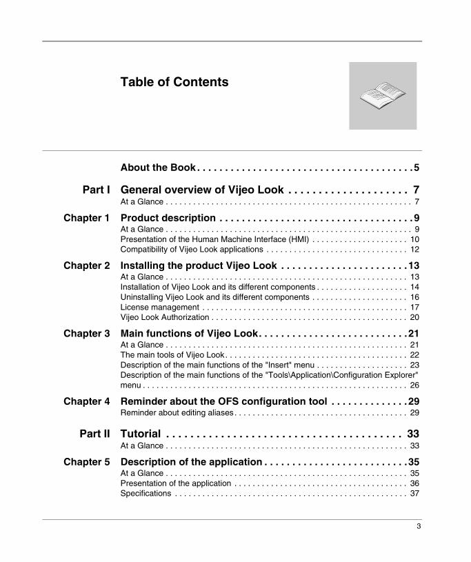
Table of Contents
About the Book . . . . . . . . . . . . . . . . . . . . . . . . . . . . . . . . . . . . . . .5
Part I General overview of Vijeo Look . . . . . . . . . . . . . . . . . . . . 7At a Glance . . . . . . . . . . . . . . . . . . . . . . . . . . . . . . . . . . . . . . . . . . . . . . . . . . . . . . 7
Chapter 1 Product description . . . . . . . . . . . . . . . . . . . . . . . . . . . . . . . . . . . 9At a Glance . . . . . . . . . . . . . . . . . . . . . . . . . . . . . . . . . . . . . . . . . . . . . . . . . . . . . . 9Presentation of the Human Machine Interface (HMI) . . . . . . . . . . . . . . . . . . . . . 10Compatibility of Vijeo Look applications . . . . . . . . . . . . . . . . . . . . . . . . . . . . . . . 12
Chapter 2 Installing the product Vijeo Look . . . . . . . . . . . . . . . . . . . . . . . 13At a Glance . . . . . . . . . . . . . . . . . . . . . . . . . . . . . . . . . . . . . . . . . . . . . . . . . . . . . 13Installation of Vijeo Look and its different components . . . . . . . . . . . . . . . . . . . . 14Uninstalling Vijeo Look and its different components . . . . . . . . . . . . . . . . . . . . . 16License management . . . . . . . . . . . . . . . . . . . . . . . . . . . . . . . . . . . . . . . . . . . . . 17Vijeo Look Authorization . . . . . . . . . . . . . . . . . . . . . . . . . . . . . . . . . . . . . . . . . . . 20
Chapter 3 Main functions of Vijeo Look. . . . . . . . . . . . . . . . . . . . . . . . . . .21At a Glance . . . . . . . . . . . . . . . . . . . . . . . . . . . . . . . . . . . . . . . . . . . . . . . . . . . . . 21The main tools of Vijeo Look. . . . . . . . . . . . . . . . . . . . . . . . . . . . . . . . . . . . . . . . 22Description of the main functions of the "Insert" menu . . . . . . . . . . . . . . . . . . . . 23Description of the main functions of the "Tools\Application\Configuration Explorer" menu . . . . . . . . . . . . . . . . . . . . . . . . . . . . . . . . . . . . . . . . . . . . . . . . . . . . . . . . . . 26
Chapter 4 Reminder about the OFS configuration tool . . . . . . . . . . . . . . 29Reminder about editing aliases. . . . . . . . . . . . . . . . . . . . . . . . . . . . . . . . . . . . . . 29
Part II Tutorial . . . . . . . . . . . . . . . . . . . . . . . . . . . . . . . . . . . . . . . 33At a Glance . . . . . . . . . . . . . . . . . . . . . . . . . . . . . . . . . . . . . . . . . . . . . . . . . . . . . 33
Chapter 5 Description of the application . . . . . . . . . . . . . . . . . . . . . . . . . .35At a Glance . . . . . . . . . . . . . . . . . . . . . . . . . . . . . . . . . . . . . . . . . . . . . . . . . . . . . 35Presentation of the application . . . . . . . . . . . . . . . . . . . . . . . . . . . . . . . . . . . . . . 36Specifications . . . . . . . . . . . . . . . . . . . . . . . . . . . . . . . . . . . . . . . . . . . . . . . . . . . 37
3

Chapter 6 Getting started . . . . . . . . . . . . . . . . . . . . . . . . . . . . . . . . . . . . . . 39At a Glance . . . . . . . . . . . . . . . . . . . . . . . . . . . . . . . . . . . . . . . . . . . . . . . . . . . . . 39Better understanding the application . . . . . . . . . . . . . . . . . . . . . . . . . . . . . . . . . . 40OFS Configuration Tool . . . . . . . . . . . . . . . . . . . . . . . . . . . . . . . . . . . . . . . . . . . . 42Communication drivers . . . . . . . . . . . . . . . . . . . . . . . . . . . . . . . . . . . . . . . . . . . . 47
Chapter 7 Configuration Explorer . . . . . . . . . . . . . . . . . . . . . . . . . . . . . . . 49At a Glance . . . . . . . . . . . . . . . . . . . . . . . . . . . . . . . . . . . . . . . . . . . . . . . . . . . . . 49The Configuration Explorer . . . . . . . . . . . . . . . . . . . . . . . . . . . . . . . . . . . . . . . . . 50Log server . . . . . . . . . . . . . . . . . . . . . . . . . . . . . . . . . . . . . . . . . . . . . . . . . . . . . . 52Smart Browser . . . . . . . . . . . . . . . . . . . . . . . . . . . . . . . . . . . . . . . . . . . . . . . . . . . 55
Chapter 8 Creating the different synoptics. . . . . . . . . . . . . . . . . . . . . . . . 57At a Glance . . . . . . . . . . . . . . . . . . . . . . . . . . . . . . . . . . . . . . . . . . . . . . . . . . . . . 57Creating the tanks . . . . . . . . . . . . . . . . . . . . . . . . . . . . . . . . . . . . . . . . . . . . . . . . 58Creating texts . . . . . . . . . . . . . . . . . . . . . . . . . . . . . . . . . . . . . . . . . . . . . . . . . . . 62Creating the "Popup" synoptic . . . . . . . . . . . . . . . . . . . . . . . . . . . . . . . . . . . . . . . 66Creating the "Web" synoptic . . . . . . . . . . . . . . . . . . . . . . . . . . . . . . . . . . . . . . . . 69Viewing the trends, setpoints and alarms . . . . . . . . . . . . . . . . . . . . . . . . . . . . . . 70Conclusion . . . . . . . . . . . . . . . . . . . . . . . . . . . . . . . . . . . . . . . . . . . . . . . . . . . . . . 73
Index . . . . . . . . . . . . . . . . . . . . . . . . . . . . . . . . . . . . . . . . . . . . . . .75
4

About the Book
At a Glance
Document Scope This manual describes how to get started with the Vijeo Look software
User Comments We welcome your comments about this document. You can reach us by e-mail at [email protected]
Vijeo Look 5

About the Book
6 Vijeo Look

Vijeo Look
I
General overview of Vijeo LookAt a Glance
Purpose of this section
This section presents the start-up of Vijeo Look and its main functions.
What's in this Part?
This part contains the following chapters:
Chapter Chapter Name Page
1 Product description 9
2 Installing the product Vijeo Look 13
3 Main functions of Vijeo Look 21
4 Reminder about the OFS configuration tool 29
7

General overview of Vijeo Look
8 Vijeo Look

Vijeo Look
1
Product descriptionAt a Glance
Subject of this Chapter
This aim of this chapter is to describe the features of Vijeo Look.
What's in this Chapter?
This chapter contains the following topics:
Topic Page
Presentation of the Human Machine Interface (HMI) 10
Compatibility of Vijeo Look applications 12
9

Product description
Presentation of the Human Machine Interface (HMI)
General Vijeo Look is an HMI (Human Machine Interface) application. It runs under Windows 2000 Professional and Windows XP Professional.The minimum configuration required is a Celeron 566Mhz processor with 128 Mb of RAM.
Vijeo Look supplies everything necessary for data acquisition, as well as for the development and visualization of animated synoptics for running PC processes. Real time data acquisition is performed using the OPC Factory Server (OFS) communications server, included in the product.
Illustration using an automated line command:
Using a simple graphic object, it is possible to visualize and /or control a motor, robot or other device by assigning one or more variables to it.
Vijeo Look
Configuration of the ani... the ani...
Grid
Shades
Textures
Speed (ms)
Grid
Shade
Textures
0
100
200
300
400500
Cars painted
Red
Blue
Green
Yellow
03
03
00
00
00
Configuration
Auto
Red
27/08/2001 08:54:52:550 Alarm on - not ack Device 1. Default0127/08/2001 08:54:53:742 Alarm on - not ack Device 1. Default01
Administrator 1 Manufacturing 27/08/01 08:51:03
10 Vijeo Look

Product description
The main features of the product are:� an advanced graphic motor, comprising:
� libraries of graphic objects that may be configured by the user,� editor of advanced native graphic elements,� management of CAD type overlays,� unlimited synoptic size,� 24 bit color support,� import of images and animations in BMP, JPEG, GIF, AVI, EMF, and WMF
formats� Zoom function,
� many types of animations,� flexible configuration of user rights,� activeX container,� VBA motor,� Java Bean container,� real time data logging tool,� interface available in English, French, German, Spanish, Italian, Chinese or
Russian,� alarm display and acknowledgement tool.
Vijeo Look 11

Product description
Compatibility of Vijeo Look applications
At a Glance All applications created using Vijeo Look V1.0, V2.0 and V2.5 can be read and executed by Vijeo Look V2.6. The application level switches automatically to V2.6. The application will no longer be accessible by an older version of Vijeo Look.
12 Vijeo Look

Vijeo Look
2
Installing the product Vijeo LookAt a Glance
Subject of this Chapter
The aim of this chapter is to describe how to install the different components of Vijeo Look.
What's in this Chapter?
This chapter contains the following topics:
Topic Page
Installation of Vijeo Look and its different components 14
Uninstalling Vijeo Look and its different components 16
License management 17
Vijeo Look Authorization 20
13

Installing the product Vijeo Look
Installation of Vijeo Look and its different components
At a Glance The product is available in CD-ROM format including the installation of Vijeo Look and OPC Factory Server, Visual Basic Application, Java virtual machine, MSDE, LapLink Gold and communication drivers.
If another version of Vijeo Look is already installed:Caution, different versions cannot be used concurrently. Consequently, they cannot both be installed on the same machine.You must reinstall Vijeo Look V1.0, V2.0 or V2.5 on another machine in order to keep the license:� Transfer the version 1, 2 or 2.5 license to the other PC,� Uninstall Vijeo Look V1.0 or V2.0 (See Uninstalling Vijeo Look and its different
components, p. 16),� Install Vijeo Look V2.6.
Note: Before going ahead with a reinstallation operation, users are advised to perform a deinstallation operation (See Uninstalling Vijeo Look and its different components, p. 16).
14 Vijeo Look
Installing the product Vijeo Look
Installing the product
Use the Setup.exe file (it starts automatically when you insert a CD-ROM in the drive) to install Vijeo Look and its components.Description of the different installation steps:
The installshield is now installing Vijeo Look and the other components you have selected.The installshield installs OPC Factory Server by default, followed consecutively by MSDE, Visual Basic Application, Vijeo Look, then Java Runtime and the communication drivers.
1 Selecting the installation language
Select the setup language you prefer:� German,� English,� Spanish,� French,� Chinese,� Italian,� Russian.
2 License contract If you accept the contract terms, go on to the next page.
3 Client information To customize the software you must enter the following information:� User name,� Company name
4 Languages Select the two languages you wish to use as well as the application default language
5 Setup type Select the setup type which best suits your needs:� Default,� Compact (with setup of the demonstration project or the
shared libraries),� Customized (allows user to choose the target directory
as well as some options in the setup)
6 Select a program folder
The setup assistant adds the program icons to the chosen program folder (Schneider Electric by default). The assistant creates a "Schneider Electric" sub-folder by default, called "Vijeo Look", containing all the tools associated with the product.
7 Launch installation Check the parameter configuration once again before launching the installation.
Note: When installation is complete, do not forget to restart your computer to ensure that all the installed components are applied.
Vijeo Look 15

Installing the product Vijeo Look
Uninstalling Vijeo Look and its different components
Description
To uninstall Vijeo Look and the other components, proceed as follows:� using the "Add/Remove programs" command in the "Control Panel", uninstall the
following programs:� Java Runtime Environment,� OFS Configuration tool,� OPC Factory Server� All the communication drivers,� Vijeo Look,� MSDE.
� reboot your machine.
Note: Before uninstalling Vijeo Look, it is vital to first transfer the software protections to another computer (see Transfer of protections, p. 18), otherwise it will be no longer possible to continue using Vijeo Look.
16 Vijeo Look
Installing the product Vijeo Look
License management
Description When setting up Vijeo Look you have 21 days to request your license from Schneider Automation.During these 21 days the status of your software is "Unauthorized" and remains so until entry of the permanent authorization code provided by Schneider Automation.
Note:OFS will be automatically authorized.
The license management software offers you the following choices:� request a permanent authorization (Vijeo Look is not yet authorized),� update the software version,� transfer the rights to another PC (provided you have the permanent authorization
code),� enter the permanent authorization code (the request should have been made
beforehand).Reminder:� if you purchase a product reference update for Vijeo Look, simply re-enter the
authorization code to obtain an upgrade of the I/O.
Vijeo Look 17

Installing the product Vijeo Look
Obtaining your license
When you first launch Vijeo Look, you are asked to enter the "serial number" and "reference number" so that your workstation may be identified in order to obtain your license.To obtain a permanent code for the software, there are several methods available: � Internet,� Internet from another PC,� Phone,� E-mail,� Fax.
When you first start Vijeo Look, you will be offered the option of registering immediately or of starting up without the authorization code for a period of 21 days. The authorization code may be obtained immediately over the Internet or by making a request by e-mail, fax or phone. Regardless of the method you choose, you will need to fill out a form. This will require your serial and reference number, as well as your computer’s identification number and installation code, both of which are generated by the software (unless you are using the Internet or E-mail in which case this information will be entered automatically).When you receive the code from Schneider Electric, you may validate the software installation on your workstation as indicated in the product documentation (unless using the Internet to get the code, in which case the code is entered automatically during connection).
Transfer of protections
You may install Vijeo Look on several machines. However, once a protection is transferred, Vijeo Look will only be active on the machine that possesses the software protections.
You may transfer a protection from one machine to another as follows (example of a transfer from machine A, containing the permanent authorization code, to machine B):� after installing Vijeo Look on machine B, start up machine B or the license
management program and choose the "authorization transfer" option, noting the machine identification number.
� start the license management program on machine A, choose the authorization transfer option, then choose either USB key transfer or network transfer, then fill in the information using the machine B identifier.
� insert the USB key into machine B and complete the transfer or follow the instructions for transferring on the network.
Note: An invalid entry may result in loss of the license.
18 Vijeo Look

Installing the product Vijeo Look
Entering the permanent authorization code
When you receive the permanent authorization code, you must enter it in the appropriate field and validate it to authorize the PC.
Performing an upgrade
There are 6 different packages for Vijeo Look:� "buildtime/runtime" 128 I/O, for a single OFS server,� "buildtime/runtime" 512 I/O, for a single OFS server,� "buildtime/runtime" 1024 I/O, for all OPC servers,� "buildtime/runtime" 2048 I/O, for all OPC servers,� "runtime" 128 I/O, for a single OFS server,� "runtime" 256 I/O, for a single OFS server,� "runtime" 1024 I/O, for all OPC servers,� "runtime" 2048 I/O, for all OPC servers.
Upon purchase of Vijeo Look, you may ask for an upgrade in order to have more I/Os.To do this, you must purchase the corresponding commercial reference and upon receipt, request a license as with a first purchase. If you are updating, the definitive (updated) version will only be effective on receipt of the definitive code issued by Schneider.
Vijeo Look 19

Installing the product Vijeo Look
Vijeo Look Authorization
Description
Vijeo Look - Authorization
Cancel< Previous
User Information Required fields are indicated with an asterisk.
Next >
First name:*
Last Name:*
Site:
Company name:*
Address:*
Address 2:
Address 3:
Town/City:*
State/Province:*
Country:*
Zip/Postal code:*
Telephone number:* Phone ext:
Fax number:*
E-mail address:*
Serial number:*
Reference number:*
Numbers only. Ex: 12345678910
Ex: VJLSMDRTSV25M
Country code:* Area code:*
Fax country code:* Fax area code:*
20 Vijeo Look
Vijeo Look
3
Main functions of Vijeo LookAt a Glance
Subject of this Chapter
This chapter describes the main functions available in the synoptics of Vijeo Look.
What's in this Chapter?
This chapter contains the following topics:
Topic Page
The main tools of Vijeo Look 22
Description of the main functions of the "Insert" menu 23
Description of the main functions of the "Tools\Application\Configuration Explorer" menu
26
21

Functions of Vijeo Look
The main tools of Vijeo Look
At a Glance The main tools of Vijeo Look are concentrated on the Visual Basic software application, the ActiveX and Beans Components, trend curves, viewers and databases.Description of the main tools:
Menu Submenu Description
Display Visual Basic Editor
This link with Visual Basic is used to develop scripts.
Insert ActiveX Control Used to insert ActiveX controls in a synoptic.It should be noted that the ActiveX controls shown in this field must be pre-selected in the menu (see Tools/Ergonomics/ActiveX Controls).
Insert Bean component Used to insert a Bean component in a synoptic.Unlike the ActiveX Controls, all Bean components shown in the Vijeo Look Project are displayed without pre-selection.
Insert Trend curves Used to view analog data as trend curves.
Insert Alarm Viewer Control
Displays the status of alarms in real time.
Insert Log Viewer Control
Displays archived data.
Draw Allows synoptics to be drawn using native graphic elements.
Animation Allows the graphic elements of a synoptic to be animated according to real time variables.
Tools Application � access to the OFS configuration via the configuration tool,
� access to the Vijeo Look configuration tool (configuration tool of the log server, data server, etc.).
Tools Project Used to open an existing project, to create a new project and to restore/archive a project.
File Edit Display Insert Drawing Order Animation Mode Tools Window ?
Display
Insert
Insert
Insert
Insert
Insert
Drawing
Animation
Tools
Tools
22 Vijeo Look

Functions of Vijeo Look
Description of the main functions of the "Insert" menu
ActiveX The ActiveX are objects that can be easily programmed using Visual Basic for Application. You can for example insert the ActiveX "Microsoft Web Browser" in order to display an HTML page (see).
Bean component Bean components are objects (like the ActiveX) used to send back data supplied by PLC variables (see).We can for example display the rotation value of a motor using an analog measuring device.Some examples of Bean Components:
Measurement devices Switch
Vijeo Look 23

Functions of Vijeo Look
Trend curves The trend curve is used to display in graphic form the evolution over time of one or more variables. Several trend curves can be concatenated in a synoptic, the only limitation being the size of the physical space available.It is also possible to insert several "Trend curve" windows into the same synoptic.Illustration:
The main characteristics of the trend curves are:� up to eight registers and/or bits can be displayed for each log,� Log and Real Time modes,� the coordinate axis (amplitude) is configurable for each "Trend curve" window,� the abscissa axis (time) is configurable between 1 second and 32767 days,� zoom functions,� an unlimited number of log displays per project.
Alarm window The alarm Viewer is an ActiveX that displays the status of the alarms. Several alarm Viewers can be created in the one synoptic, the only limitation being the size of the physical space available.Illustration:
The main characteristics of the alarm Viewers are:� an unlimited number of alarm Viewers in each project,� the format of the alarm text is totally configurable.
14:13:20 14:13:30 14:13:40 14
Date Hour Title Name24/08/01 10:36:25:532 Alarm on - not ack Device1.Default0124/08/01 10:36:25:532 Alarm on - not ack Device1.Default01
24 Vijeo Look

Functions of Vijeo Look
Log window The Log Viewer is an ActiveX control which displays the data saved in the data base. It is possible to display all the data or, by using filters, to display only a part of the data. Several Log Viewers can be inserted into a synoptic, the only limitation being the size of the physical space available.
The main characteristics of the Log Viewer are:� an unlimited number of Log Viewers for each project,� for each Log Viewer, one or more filters can be created,� Display:
� change in an alarm's status,� change in a bit's status,� change in a word's value.
Vijeo Look 25

Functions of Vijeo Look
Description of the main functions of the "Tools\Application\Configuration Explorer" menu
General Certain "Configuration Explorer" tabs appear only if the "Advanced parameters" option is selected from the "Display" menu of "Configuration Explorer".
General parameters
Using the general parameters, you can configure: � the filters,� associated labels� the properties of variables,� the property ranges of variables.
Log server The log data server collects and saves data in real time from the Real Time Data Server. The trend and log viewers display the logged data.
This version of the software is compatible with the following standard databases:� MSDE (Microsoft SQL Server Desktop Engine),� Access 2000.
26 Vijeo Look

Functions of Vijeo Look
Data server The data server is used to create and set the variables (bit, register, text) to be used in the block diagrams and/or archived.It is also used to enhance the properties of variables by adding user parameters. Illustration:
Persistent
Configuration ExplorerFile Display Smart Browser
CancelSet
Server name
Variable type
Trend
Alarm
General parameters
OFS
Bit
Device3!InputStatus1
_ DEFAULT _
Logging
HMI access
Internal
External
Variable Properties Extended Properties
Options
Type
NameDevice3.InputStatus1
Data type
28/07/2004 15:51ReadyExplorer Config Smart Browser
Log serverData server
OPC serverOFS
VariablesBuildingDevice1:Device3
_SpecificCoil1HoldingReg1InputReg1InputStatus1
Food_BeverageGeneralMachinesManufacturing
WaterPlantTEST_BARGRAPHTEST_COMMAND
System
Associated Label
0 1
0 1
0 1
Vijeo Look 27

Functions of Vijeo Look
28 Vijeo Look
Vijeo Look
4
Reminder about the OFS configuration toolReminder about editing aliases
Definition An alias is a variable used by OFS whose properties include a name, a communication protocol and a table of symbols file (this last property being optional).
29

Reminder about creating aliases
Creating an alias Aliases are edited using the OFS configuration tool, named "OFSconf.exa", which is found in: ...\Ofs\OFSconf\OFSconf.exe.The OFS Configuration Tool main window shows the aliases listed in a grid, the "Server Mode" option and the "Group Min Update Rate". This data covers most user requirements.
Illustration:
Note: Vijeo Look is preconfigured with OFS. Several aliases have been created for the operation of the demonstration project.
OFS Configuration
Welcome to the OPC Factory Server Configuration tool
1000
2 11/10/01
Properties ofms
Group Min Update Rate
Server modeHiddenControlDiag.Verbose Diag.
List of PLC aliases
Building
Device1
Device2
Device3
UNTLW01:1.2.0
UNTLW01:0.254.0
UNTLW01:1.3.0
MBT:1.2.3.4
Name <driver>:<API adr> Symbols table file
Server Edit ?Print
???
Advanced...
aliases ...
Number of aliases: 8
4
Ok Cancel Apply
Food_Beverage UNTLW01:1.4.0
Alias
Description
C:\Program Files\Schneider Electric\Vijeo Look\Projects\Demo\OFS Files\Building.csv
MachinesManufacturing
WaterPlant
UNTLW01:1.50
UNTLW01:1.6.0
UNTLW01:1.7.0
C:\Program Files\Schneider Electric\Vijeo Look\Projects\Demo\OFS Files\Device1.csvC:\Program Files\Schneider Electric\Vijeo Look\Projects\Demo\OFS Files\Device2.csv
C:\Program Files\Schneider Electric\Vijeo Look\Projects\Demo\OFS Files\Device3.csv
C:\Program Files\Schneider Electric\Vijeo Look\Projects\Demo\OFS Files\Food_Beverage.csv
C:\Program Files\Schneider Electric\Vijeo Look\Projects\Demo\OFS Files\Machines.csvC:\Program Files\Schneider Electric\Vijeo Look\Projects\Demo\OFS Files\Manufacturing.csv
C:\Program Files\Schneider Electric\Vijeo Look\Projects\Demo\OFS Files\WaterPlant.csv
C:\Program Files\Schneider Electric\OFS\Server\Ofs.exe
30 Vijeo Look

Reminder about creating aliases
The table below describes the fields of the above screen:
The aliases grid is made up of 3 columns which contain the most important information on each device.
Creating an alias involves:� assigning a name,� defining the network address of the device, which includes the network driver and
the device address,� Providing a Symbols table file name (optional),� setting the alias properties which are related to how the server will behave
towards the variables created on that alias.These operations are all accessible via click-sensitive areas in the grid and the "Alias properties" button.
Server mode Hidden: the server is invisible on the screen.Control: the server is iconized but only the system menu is accessible (right mouse click).Diag.: a complete set of diagnostics windows is displayed during server execution, including a plotting window displaying warning and/or error messages.Verbose diag.: the plotting window displays detailed information messages in addition to errors and warnings. The rest is identical to "Diag." mode.
Group Min Update Rate
Minimum update rate allowed for groups. The update rate should be set by the client as a multiple of this value. Numerical value in ms. Range: [10..32767]
"Advanced" button
Display seven additional tabs for experienced users.
Alias name Here the user may enter up to 50 characters of text in order to identify the configuration of the aliases entered.This text appears at the top of the print file. If you make a back-up copy, it is saved in the chosen file. It is not included in the configuration of the OFS server.
OK Configuration validation and exiting the Configuration tool.
Apply Configuration validation without exiting the Configuration Tool.
Cancel Canceling modifications made since the Configuration tool was launched or since the "Apply" button was activated.A confirmation request message is displayed.
Note: The information on the number of aliases declared is displayed. The "Create new alias" and "Clear current alias" buttons allow an alias to be added to the grid and the selected alias to be deleted.
Vijeo Look 31

Reminder about creating aliases
Sort function in the grid:The aliases can be arranged in the grid according to the parameters associated with the alias:� Name of alias, driver, symbols table file. Simply click on the upper strip of the grid
in the appropriate column. Arrangement in alphabetical order.� Other parameters: activate the "Edit ->Sort" menu and select the parameter you
want. They are arranged alternately in increasing, or (by clicking again) decreasing order of values (e.g.: for a binary value parameter, increasing signifies all the aliases with the value 0, then all those with the value 1).
Symbols table file
A symbols table file can be associated with the alias, in order to provide access to the symbols for the variables of this device. The symbols file is generated by the PLC programming software, e.g. PL7 for Premium/Micro, Concept for Quantum or Unity Pro.Clicking in the "Symbols table file" area for the selected alias in the grid brings up a file explorer:The file types that can be inserted are listed in the "type of files" list box. Select the appropriate file type.Enter the file of your choice and click on "Open". The file name and directory will then be displayed in the grid.
Note: Once an alias has been created, it is necessary to close and then reopen the OFS server to integrate any modifications made using the configuration tool.
CAUTION
Using the aliases
A device should be associated with a single and unique alias. If two aliases point to the same device and are used simultaneously, the communication will malfunction. The properties will be the same for both, and set to the properties of the alias first used to create an item. In the same way, using an alias and accessing the same device directly from the address will have similar results.
Failure to follow this precaution can result in injury or equipment damage.
32 Vijeo Look

Vijeo Look
II
TutorialAt a Glance
Purpose of this section
This section offers a step by step description of the creation of a simple application implementing Vijeo Look's main functions.
What's in this Part?
This part contains the following chapters:
Chapter Chapter Name Page
5 Description of the application 35
6 Getting started 39
7 Configuration Explorer 49
8 Creating the different synoptics 57
33

Tutorial
34 Vijeo Look

Vijeo Look
5
Description of the applicationAt a Glance
Subject of this Chapter
This chapter gives a general description of the application and the specifications.
What's in this Chapter?
This chapter contains the following topics:
Topic Page
Presentation of the application 36
Specifications 37
35

Description of the application
Presentation of the application
Description This tutorial will guide you in the creation of a simple application in Vijeo Look. We will create a simple application that uses the application's main functions. You will create two tanks each containing a liquid of a different color. These tanks will be filled and emptied automatically. To interpret the operation of the tanks as realistically as possible, you will create an alarm activated when the threshold level (defined by the user) is reached. An indicator light will change color to signal the alarm.On the main screen, three buttons are used to open popup windows giving more detailed information on the tanks, or to open the "www.telemecanique.com" Internet site. Moreover, you will create three graphs used to interpret the operation of the tanks:� view trends� view setpoints� view alarms
This application highlights the Vijeo Look programming concepts, in particular those of objects and branches and the enhancement of variables.
i
Vijeo Look
Main
Tank 1 level: 52 Liters
www.telemecanique.com
Enter the alarm activation value for tank 1:
24.00 Liters
View trends
00 12:27:00 12:28:00 12:29:00 12:30:
View setpointsDate Time Title Name Value
29/10/200229/10/200229/10/200208/11/200208/11/200213/11/200213/11/200213/11/2002
10:42:05:57811:41:30:57811:41:45:92116:32:53:93716:33:05:96810:37:13:75010:56:26:06216:26:45:625
Change valueChange valueChange valueChange valueChange valueChange valueChange valueChange value
tank_lev_1 .Alarm....tank_lev_1 .Alarm....tank_lev_1 .Alarm....tank_lev_1 .Alarm....tank_lev_1 .Alarm....tank_lev_1 .Alarm....tank_lev_1 .Alarm....tank_lev_2 .Alarm....
12.0085.0010.0010.0082.0012.0024.0026.00
View alarmsDate Time Title Name
13/11/200213/11/2002
09:42:50:01509:42:50:015
Present alarm acknowledgedAlarm idle
tank_lev_1 .Alarm.tank_fulltank_lev_2 .Alarm.tank_full
tank 2 parametertank 1 parameter
Enter the alarm activation value for tank 2:
90.00 Liters
Tank 2 level: 60 Liters
File Edit Display Insert Drawing Order Animation Mode Tools Window ?
36 Vijeo Look

Description of the application
Specifications
Description The application:a synoptic displayed on the same page:� a tank whose 'Tank Level 1' value is represented graphically and a text which
displays the 'Tank Level 1' value according to the tank level, � an indicator light at the top of the tank which changes color when an alarm
associated with the 'Tank Full 1' is activated, � a setpoint field used to enter the 'Higher tank Limit 1' value, � a button used to open a popup window which:
� displays the numeric value of 'Tank Level 1' with its unit,� shows this value via the Mtr_Meter08.ANI object located in the Meter
directory,� contains a button used to close the popup window,
� a tank whose 'Tank Level 2' value is represented graphically and a text which displays the 'Tank Level 2' value according to the tank level,
� an indicator light at the top of the tank which changes color when an alarm associated with the 'Tank Full 2' is activated,
� a setpoint field used to enter the 'Higher tank Limit 2' value, � a button used to open a popup window which:
� displays the numeric value of 'Tank Level 2' with its unit,� shows this value via the Mtr_Meter08.ANI object located in the Meter
directory,� contains a button used to close the popup window,
� a view of the alarms,� a view of the trends,� a view of the setpoints,
� a button used to open a popup window which:� displays the contents of the www.telemecanique.com Web page,� contains a button used to close the popup window.
Vijeo Look 37

Description of the application
The variables:� an analog ‘Tank Level 1' variable, assigned on Uni-Telway in simulated mode,
which will be saved in the table of trends (period: 30 seconds),� an analog ‘Tank Level 2' variable, assigned on Modbus in simulated mode, which
will be saved in the table of trends (period: 10 seconds),� an internal analog 'Higher Tank Limit 1' variable will be saved in the table of
setpoints,� an internal analog 'Higher Tank Limit 2' variable will be saved in the table of
setpoints,� an internal Boolean ‘Tank Full 1' variable representing an alarm activated when
the ‘Tank Level 1' value is greater than the 'Higher Tank Limit 1' value,� an internal Boolean ‘Tank Full 2' variable representing an alarm activated when
the ‘Tank Level 2' value is greater than the 'Higher Tank Limit 2' value.
The database tables:The database will be the default database.A setpoint table and a trend table will be created for each tank.� for the variables concerning tank 1: Trend_tank_1 & Log_tank_1,� for the variables concerning tank 2: Trend_tank_2 & Log_tank_2.
38 Vijeo Look

Vijeo Look
6
Getting startedAt a Glance
Subject of this Chapter
This chapter is intended to help you create your application.
What's in this Chapter?
This chapter contains the following topics:
Topic Page
Better understanding the application 40
OFS Configuration Tool 42
Communication drivers 47
39
Getting started
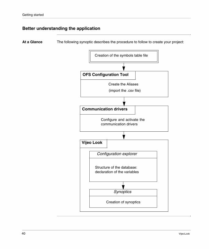
Better understanding the application
At a Glance The following synoptic describes the procedure to follow to create your project:
Configure and activate thecommunication drivers
Create the Aliases
(import the .csv file)
Vijeo Look
Structure of the database:declaration of the variables
OFS Configuration Tool
Communication drivers
Configuration explorer
Creation of synoptics
Synoptics
Creation of the symbols table file
40 Vijeo Look

Getting started
Concept of a branch
To minimize the application development part, we will use the Vijeo Look branch concept.First of all, the specifications must be correctly interpreted.Basically, we must create two tanks which will behave in exactly the same way, i.e., the tanks will be filled and an alarm will be activated at a given level. These behaviors are associated with three variables: "Level", "HigherLimit" and "Full" respectively. The branch concept in Vijeo Look consists in declaring the variables once only and using them in different branches. Here, we can say that tank 1 is equivalent to device 1 and tank 2 equivalent to device 2. Devices 1 and 2 define the branches. Why use a branch concept?The branch concept is used to create structures and to reuse generic objects.In the diagram below, the generic object can be declared either on branch 1, or on branch 2. The "Level", "HigherLimit" and "Full" variables are common to both branches.
the same object can be used as many timesas necessary. The variables are common toboth tanks, only the branch differs.
SynopticStructure of the Variables
LevelHighLimit
Full
Generic objectBranch1device1
Branch2device2
device1ordevice 2
. Level
Vijeo Look 41

Getting started
OFS Configuration Tool
At a Glance Before you launch Vijeo Look, you must create all your project's aliases (See Reminder about editing aliases, p. 29) using the OFS Configuration Tool.A symbol table (See Symbols table file, p. 32)* file will be assigned to each alias. In the example, the CSV file will be created manually to highlight the branch concept.
* how do you create a "symbols table" file? :� export the symbols table from PL7 or Concept,� create the symbols file manually.
42 Vijeo Look

Getting started
Symbols table file
The table below describes the procedure to follow to manually create the symbols table using Microsoft Excel:
Step Action
1 run EXCEL.exe
2 open a new document
3 � declaration of the "Tank Level 1" variable corresponding to the tank level:� on the first row, in the first cell, enter "%MW1001" → the variable, � on the first row, in the second cell, enter "Tank1.Level" → the symbol, � on the first row in the third cell, enter "Current level of tank 1" → the
comment, � declaration of the "Higher Tank Limit 1" variable corresponding to the alarm
activation threshold value:� on the second row, in the first cell, enter "%MW1003" → the variable, � on the second row, in the second cell, enter "Tank1.HigherLimit" → the
symbol, � on the second row, in the third cell, enter "Higher limit of tank 1" →
the comment, � declaration of the "Tank Full 1" variable corresponding to the alarm:
� on the third row, in the first cell, enter "%M1005" → the variable, � on the third row, in the second cell, enter "Tank1.Full" → the symbol, � on the third row, in the third cell, enter "Alarm of tank 1" → the comment,
4 save your file as "Tank1.csv" in C:\Program Files\Schneider Electric\Vijeo Look\Projects\tutorial\OFS Files (the directories "tutorial and OFS Files" must have been created beforehand).
5 � repeat steps 3 and 4 to create the variables "Tank Level 2", "Higher Tank Limit 2" and "Tank Full 2".
� save your file as "Tank2.csv" in C:\Program Files\Schneider Electric\Vijeo Look\Projects\tutorial\OFS Files.
File Edit Display Insert Format Tools Data Window ?
Microsoft Excel - Tank1.csv
%MW1001
A D
%MW1003
%M1005
Tank1.Level
B
Tank1.HigherLimit
Tank1.Full
Current level of tank 1
C
Higher limit of tank 1
Alarm of tank 1
12
3
4
A1 = %MW1001
ABC
Vijeo Look 43

Getting started
Creating aliases OFS Configuration Tool screen:
OFS Configuration Tool
Welcome to the OPC Factory Server Configuration tool
1000
2 11/10/01
Properties ofms
Group Min Update Rate
Server modeHiddenControlDiag.Verbose Diag.
List of PLC aliases
device1 UNTLW01:0.254.0
Name <driver>:<API adr> Symbols table file
Server Edit Print
???
Advanced...
aliases ...
Number of aliases: 8
4
Ok Cancel Apply
Alias
Description
C:\Program Files\Schneider Electric\Vijeo Look\Projects\tutorial\OFS Files\Tank1.csv
C:\Program Files\Schneider Electric\OFS\Server\Ofs.exe
Help
C:\Program Files\Schneider Electric\Vijeo Look\Projects\tutorial\OFS Files\Tank2.csvMBT:139.160.234.126/T
device2
44 Vijeo Look

Getting started
The table below describes the procedure to follow to create aliases:
Step Action
1 Start the OFS Configuration Tool (via the Start menu / Programs / Schneider Electric / OFS Configuration Tool).
2 Click on the green "Create new alias" icon.
3 In the Name cell, enter "device1".
4 In the <driver>:<API adr> cell, click on the drop-down menu to the right of the cell (the "configure driver" window opens).
5 � expand the XWAY menu by clicking on the "+" sign and click on UNITELWAY, � enter the following values: "Network = 0", "Station = 254" and "Gate = 0" in the
Network address field.
6 Click on Validate.
7 In the "Symbols table file" cell:� expand the menu (click on the arrow) to the left of the cell to select the "Tank1.csv"
file created beforehand (See Symbols table file, p. 43). This file is located in "C:\Program Files\Schneider Electric\Vijeo Look\Projects\tutorial\OFS Files".
8 Click on Open.
9 Adjust the "Group Min Update Rate" = 200 ms (minimum update period for the groups).
10 Validate the "diagnostic" server mode.
11 Click on the "Alias properties" button and validate "Simulation" if you wish to perform a simulation.
12 In the menu bar, click on "Server" then on "Archive aliases".
Vijeo Look 45

Getting started
Creating aliases for tank 2:Proceed in the same way as you did for "Creating aliases for tank 1", changing the name of the "device1" alias to "device2".
Caution: the "Tank level 2" analog variable is assigned on Modbus. Consequently, for step 5, expand the Modbus menu by clicking on the "+" sign, click on TCP IP then enter the TCP/IP address of the TSX Premium. In the "Options" field, check the "TSX Premium" check box, then click on "Validate".
devModbus+ : Click on the driver name
MODBUS
ALIAS ADDRESS
XWAY OTHERS
Validate
Cancel
Erase
Instance number
OPTIONSNoneJBUS
TSX
TCP IP / DNS
MODBUS
XWAYOTHER
RTUTCP IPPLUS
TCP IP
DNS
MBP bridge index
RTUCOM1COM2COM3COM4
APInode
Master DataMaster Program
PLUS
MBT:139.160.234.126/T
Optional nodes
Driver: PLUS
139 160 234 126
46 Vijeo Look
Getting started
Communication drivers
Description Once you have created the aliases, you must configure and activate the communication drivers (the Uni-Telway driver is provided with the product).
Vijeo Look 47

Getting started
48 Vijeo Look

Vijeo Look
7
Configuration ExplorerAt a Glance
Subject of this Chapter
This chapter describes the procedure for declaring variables on the RTDS server.The configuration explorer is used to configure the data server (RTDS) and the log server (HDS).
What's in this Chapter?
This chapter contains the following topics:
Topic Page
The Configuration Explorer 50
Log server 52
Smart Browser 55
49

Configuration Explorer
The Configuration Explorer
Description The data server is used to create and set up the variables (bit, register, text) to be used in synoptics and/or archived.The variables are declared in the configuration explorer, accessible via Vijeo Look as indicated in the screen below:
Data server Firstly, remember to check that the variables declared in the OFS Configuration Tool have been uploaded to the data server:
i
Vijeo Look
Project
SecurityErgonomics
Display language
Project language
Keyboard manager ...
Expression editor ...Acceptance editor ...
Options ...
Configuration Explorer …
Logged Data Server …
OFS Configuration Tool … F11
F12
Application
File Edit Display Insert Drawing Orrder Animation Mode Tools Window ?
Step Action
1 Open "Configuration Explorer"
2 Open the "data server" directory
3 Open the "variables" directory
4 Open the "device1" directory
5 Open the "Tank1" directory
50 Vijeo Look

Configuration Explorer
You should obtain the screen below, with the Full, HigherLimit and Level variables for each device (branch concept):
Step Action
1 Go to the "Full" bit
2 In the left-hand screen, check the "Alarm" check box in the Option field, then click on "Define"
3 Go to the "HigherLimit" register
4 In the left-hand screen, check the "Log" check box in the Option field, then click on "Define"
5 Go to the "Level" register
6 In the left-hand screen, check the "Trend" and "HMI Access" check boxes in the Option field, then click on "Define"
7 Repeat steps 4 to 11 to configure the branch 2's "Level", "HigherLimit" and "Full" variables
8 Save the configuration (File / Save)
File Display
Configuration Explorer
General parametersLog serverData server
OPC serversVariables
System
device1_Specific
Level
HigherLimitFull
device2_Specific
LevelHigherLimit
Full
0 1
0 1
Tank1
Tank2
Branch 1
Branch 2
Vijeo Look 51

Configuration Explorer
Log server
Description The log server (HDS) is used to configure one or more databases to record trends and log entries.
Trend tables Procedure to follow to configure the trend table:
File Display
Configuration Explorer
General parametersLog server
DatabasesDefault DB
Variables tablesTrend tables
trend_tank1
Log tablestrend_tank2
log_tank1log_tank2
Log listsLog_List_tank1Log_List_tank2
Trend groupsTrend_Group_15Trend_Group_30
Data server
device 1
device 2
Step Action
1 Open the "Log server" directory
2 Open the "Databases" directory
3 Open the "DefaultDB" directory
4 Open the "Trend tables" directory
5 Position your cursor on the "Trend tables" directory, right-click and choose "New"
6 Enter the name of the trend table: "trend_tank1". This name will be used for device 1
7 Click on "Define".
Note: Repeat steps 1 to 7 to declare the "trend_tank2" trend table which will be used for device 2.
52 Vijeo Look

Configuration Explorer
Log tables Procedure to follow to configure the log table:
Trend groups Trend groups are used to configure groups that define each variable's recording period.Procedure to follow to configure the trend group:
Step Action
1 Open the "Log server" directory
2 Open the "Databases" directory
3 Open the "DefaultDB" directory
4 Open the "Log tables" directory
5 Position your cursor on the "LogTable" directory, right-click and choose "New"
6 Enter the name of the log table: "log_tank1". This name will be used for device 1
7 Click on "Define".
Note: Repeat steps 1 to 7 to declare the "log_tank2" log table which will be used for device 2.
Step Action
1 Open the "Log server" directory,
2 Open the "Trend group" directory
3 Position your cursor on the "Trend10sec" directory, right-click and choose "New"
4 Enter the name of the trend group: "Trend_Group30". This name will be used for device 1
5 In the "Update period / Sampling period" field, specify 30 seconds
6 Click on "Define".
Note: Repeat steps 1 to 6 to declare the "Trend_Group15" trend table which will be used for device 2.
Vijeo Look 53

Configuration Explorer
Log lists Log lists are used to configure lists that define which events will be recorded, and where.Procedure to follow to configure the log list:
Step Action
1 Open the "Log server" directory
2 Open the "Log lists" directory
3 Position your cursor on the "MyLogList" directory, right-click and choose "New"
4 Enter the name of the list: "Log_List_tank1". This name will be used for device 1
5 In the "Database" field:� Name: Leave "DefaultDB",� Table / Name: uncheck the "By default" check box, then select "log_tank1"
using the drop-down menu.
6 Click on "Define".
Note: repeat steps 1 to 6 to declare the "Log_List_tank2" list which will be used for device 2.
54 Vijeo Look

Configuration Explorer
Smart Browser
Description When set to search mode Smart Browser can be used to list a group of variables, by way of a filter applied to the variable name and the Trend, Log, Alarm and HMI Access properties.Illustration
When set to edit modeSmart Browser can be used to modify the Trend, Log, Alarm and HMI Access properties of the entire selected list.
Search
File Display
Like
0 1 Building.Alarms.Ala_Fresh
*Ala*Variable
Options Type
Trend
Alarm
Search4 variables found.
CloseAdd to Smart Browser
Logging
HMI access
Variable Name
General Advanced Extended Properties
0 1
Abc
0 1 Building.Alarms.Ala_Registers0 1 Building.Power.Ala
0 1 Building.Alarms.Ala_Frozen
Vijeo Look 55

Configuration Explorer
Illustration
Persistent
Configuration ExplorerFile Display Smart Browser
CancelSet
Server name
Variable type
Trend
Alarm
Bit
_ DEFAULT _
Logging
HMI access
Internal
External
Variable Properties Extended Properties
Options
Type
Name
Data type
30/07/2004 17:03ReadyExplorer Config Smart Browser
Associated Label
Alarm
Select Mode Find...
0 1 Building.Alarms.Ala_Fresh
0 1 Building.Alarms.Ala_Registers0 1 Building.Power.Ala
0 1 Building.Alarms.Ala_Frozen
Variable Name
56 Vijeo Look

Vijeo Look
8
Creating the different synopticsAt a Glance
Subject of this Chapter
This chapter describes the implementation of Vijeo Look's main functions. Throughout this chapter, we will explain the procedure to follow to create synoptics.
What's in this Chapter?
This chapter contains the following topics:
Topic Page
Creating the tanks 58
Creating texts 62
Creating the "Popup" synoptic 66
Creating the "Web" synoptic 69
Viewing the trends, setpoints and alarms 70
Conclusion 73
57
Creating the different synoptics
Creating the tanks
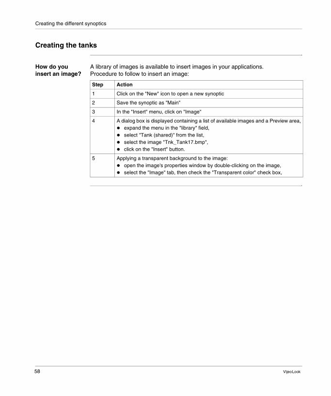
How do you insert an image?
A library of images is available to insert images in your applications.Procedure to follow to insert an image:
Step Action
1 Click on the "New" icon to open a new synoptic
2 Save the synoptic as "Main"
3 In the "Insert" menu, click on "Image"
4 A dialog box is displayed containing a list of available images and a Preview area,� expand the menu in the "library" field,� select "Tank (shared)" from the list,� select the image "Tnk_Tank17.bmp", � click on the "Insert" button.
5 Applying a transparent background to the image:� open the image's properties window by double-clicking on the image,� select the "Image" tab, then check the "Transparent color" check box,
58 Vijeo Look

Creating the different synoptics
How do you create a bar chart?
Using a bar chart, the value of a measurement is represented by filling in a drawing element. We will apply a bar chart to a rectangle and use the value of the "Level" variable to fill in the tank.Throughout the design process, you will create generic symbols. A generic symbol comprises:
Procedure to follow to create a bar chart:
Step Action
1 Using the drawing tools, draw a vertical rectangle above the tank,
2 � select the rectangle then open the properties panel (right-click and choose Properties),
� in the "Drawing" tab, apply "Invisible" in the "color" field,� in the "Aspect" tab, select "Relief" in the "Appearance" field,� click "OK".
3 Select the rectangle,
4 Right-click and choose Animation / Color / Bar Chart.An additional "Bar Chart" tab is created in the "Object properties" window
5 � in the "Measurement" field: enter "Level",� in the color field, choose a color for the "Bar" area then apply a transparent
background,� in the "Amplitude" field, enter 0 for the minimum amplitude and 100 for the
maximum amplitude by clicking on the "Static value" mode,� click "OK".
Caution: ignore the yellow triangle at the top left of the rectangle.
6 Group the tank and the rectangle (select the tank and the rectangle, right-click and choose "Group")
7 Select the group created above, then right-click and choose "Create symbol"� enter "device" in the "Name" field,� click "OK".
8 Delete the previous symbol.Note: you have just created a generic symbol. Once you have saved your symbol, delete the one used to create it.
1 Image 1 Animation 1 Generic symbol=+
Vijeo Look 59

Creating the different synoptics
Using symbols with a branch
Symbols contain animations that use a reference to relative variables. You must therefore provide a branch. You can enter the branch directly, use the branch selector, or use substitution characters.Procedure to follow to insert the "device" symbol:
To check that your application works properly, switch the synoptic to "Execute" mode (menu: Mode / Execute).
Step Action
1 � menu: Insert / Symbol,� select "device", � in the "Branch" field, click on the arrow to the right to open the "Branch selector"
window,
� click on the icon
� open directory "device1", select "Tank1" to obtain the "device1.Tank1" branch, then click on "Apply"
� click on "Insert".
2 Click "OK"
3 Save your application.
i
Vijeo Look
Main
File Edit Display Insert Drawing Order Animation Mode Tools Window ?
60 Vijeo Look

Creating the different synoptics
Creating tank 2 The elements that make up tank 2 are the same as those for tank 1. It will only take a few seconds to create them. Proceed as follows:Procedure to follow to change branches:
Since the "Level" variable is used both for tank 1 and tank 2, the creation of tank 2 is easy. You simply change the call to the branch.
Step Action
1 � menu: Insert / Symbol,� select "device", � in the "Branch" field, click on the arrow to the right to open the "Branch selector"
window,
� click on the icon
� open directory "device2", select "Tank2" to obtain the "device2.Tank2" branch, then click on "Apply"
� click on "Insert".
2 click "OK"
3 save your application.
Vijeo Look 61

Creating the different synoptics
Creating texts
How do you create a text?
Procedure to follow to create a text:
Displaying the measurement value
There are two animations, "Measurement Value" and "Measurement Value on State" used to display a measurement value as a numeric data item.Procedure to follow to create an animation on a text:
Step Action
1 Click on the "Text" icon, or select the menu: Drawing / Text
2 Enter "Tank 1 level:"
3 � select the text then right-click to open the properties window,� in the "Text / Color" field, apply the color black, � in the "Text / Text background" field, apply a transparent color,
� to modify the font, click on the icon .
4 Click "OK" to close the text properties window.
Step Action
1 Click on the "Text" icon, or select the menu: Drawing / Text
2 Enter "Value"
3 � select the text then right-click to open the properties window,� in the "Text / Color" field, apply the color black, � in the "Text / Text background" field, apply a transparent color,
� to modify the font, click on the icon .
4 Click "OK" to close the text properties window.
5 Select the text then right-click and choose "Animation / Text / Measurement", A new tab is displayed in the text's properties window.
6 In the "Measurement" field, enter "Level" then click "OK"
7 Resize the cell correctly so that the numeric value and its unit are visible in execute mode
8 Select the "Tank 1 level:" text and the "Value" text, right-click and group them
9 select the group created above then: � right-click and choose "Create symbol",� enter "text" in the "Name" field,� click "OK".
10 Delete the previous symbol.Note: you have just created a generic symbol. Once you have saved your symbol, delete the one used to create it.
62 Vijeo Look

Creating the different synoptics
Inserting the "text" symbol in the "Main" synoptic:
Step Action
1 � menu: Insert / Symbol,� select "text", � in the "Branch" field, click on the arrow to the right to open the "Branch selector"
window,
� click on the icon
� open directory "device1", select "Tank1" to obtain the "device1.Tank1" branch, then click on "Apply",
� click on "Insert".
2 Click "OK" to close the window
3 Save your application.
i
Vijeo Look
Main
Tank 1 level: 52 Liters
Enter the alarm
activation value for tank 1: 30.00 Liters
File Edit Display Insert Drawing Order Animation Mode Tools Window ?
Vijeo Look 63
Creating the different synoptics
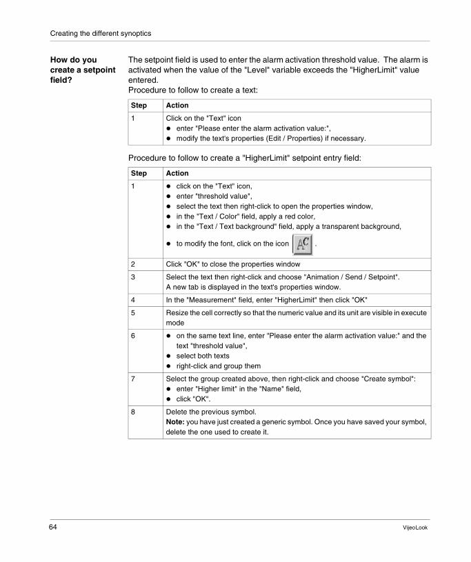
How do you create a setpoint field?
The setpoint field is used to enter the alarm activation threshold value. The alarm is activated when the value of the "Level" variable exceeds the "HigherLimit" value entered.Procedure to follow to create a text:
Procedure to follow to create a "HigherLimit" setpoint entry field:
Step Action
1 Click on the "Text" icon � enter "Please enter the alarm activation value:",� modify the text's properties (Edit / Properties) if necessary.
Step Action
1 � click on the "Text" icon, � enter "threshold value",� select the text then right-click to open the properties window,� in the "Text / Color" field, apply a red color, � in the "Text / Text background" field, apply a transparent background,
� to modify the font, click on the icon .
2 Click "OK" to close the properties window
3 Select the text then right-click and choose "Animation / Send / Setpoint". A new tab is displayed in the text's properties window.
4 In the "Measurement" field, enter "HigherLimit" then click "OK"
5 Resize the cell correctly so that the numeric value and its unit are visible in execute mode
6 � on the same text line, enter "Please enter the alarm activation value:" and the text "threshold value",
� select both texts� right-click and group them
7 Select the group created above, then right-click and choose "Create symbol":� enter "Higher limit" in the "Name" field,� click "OK".
8 Delete the previous symbol.Note: you have just created a generic symbol. Once you have saved your symbol, delete the one used to create it.
64 Vijeo Look

Creating the different synoptics
Inserting the "Higher limit" symbol in the "Main" synoptic:
In real circumstances, the alarm will be activated when the "Level" variable exceeds the "HigherLimit" variable. The application you have just created is in simulated mode, which implies the use of a system bit whose state changes every second: the indicator light flashes.
How do you create the text for tank 2?
The texts for tank 2 are the same as those for tank 1. It will only take a few seconds to create them.Procedure to follow to create the tank 2 text:
Step Action
1 � menu: Insert / Symbol,� select "Higher limit", � in the "Branch" field, click on the arrow to the right to open the "Branch selector"
window,
� click on the icon
� open directory "device1", select "Tank1" to obtain the "device1.Tank1" branch, then click on "Apply",
� click on "Insert".
2 Click "OK" to close the window
3 Save your application.
Step Action
1 � insert the "text" and "Higher limit" symbols in the "Main" synoptic� select "Higher limit", � in the "Branch" field, click on the arrow to the right to open the "Branch selector"
window,
� click on the icon
� open directory "device2", select "Tank2" to obtain the "device2.Tank2" branch, then click on "Apply",
� click on "Insert".
2 Click "OK" to close the window
3 Save your application.
Vijeo Look 65
Creating the different synoptics
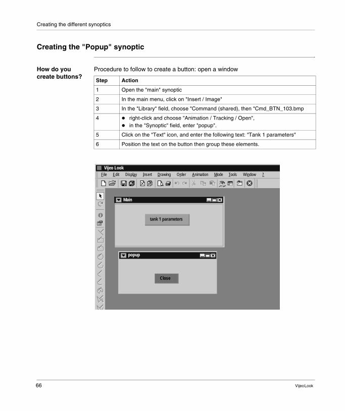
Creating the "Popup" synoptic
How do you create buttons?
Procedure to follow to create a button: open a window
Step Action
1 Open the "main" synoptic
2 In the main menu, click on "Insert / Image"
3 In the "Library" field, choose "Command (shared), then "Cmd_BTN_103.bmp
4 � right-click and choose "Animation / Tracking / Open",� in the "Synoptic" field, enter "popup".
5 Click on the "Text" icon, and enter the following text: "Tank 1 parameters"
6 Position the text on the button then group these elements.
i
Vijeo Look
Main
tank 1 parameters
popup
Close
File Edit Display Insert Drawing Order Animation Mode Tools Window ?
66 Vijeo Look

Creating the different synoptics
Procedure to follow to create a button: close a window, this "Close" button is located in the "popup" synoptic.
Creating the "popup" synoptic
The "popup" synoptic is made up of a control screen and a "Close" button:
Step Action
1 Open the "main" synoptic
2 In the main menu, click on "Insert / Image"
3 In the "Library" field, choose "Command (shared), then "Cmd_BTN_101.bmp
4 � right-click and choose "Animation / Tracking / Close",� in the "Synoptic" field, enter "popup".
5 Click on the "Text" icon, and enter the following text: "Close"
6 Position the text on the button then group these elements.
Step Action
1 Open a new synoptic
2 Save the new synoptic as "popup" (menu bar / Save as)
3 In the menu bar, click on Insert / Symbol: � in the library field, expand the menu and choose "Meter (shared)",� click on "Mtr_Meter08.ANI" then on "Insert",� in the "Branch" field, click on the arrow to the right to open the "Branch selector"
window,
� click on the icon
� open directory "device1", select "Tank1" to obtain the "device1.Tank1" branch, then click on "Insert",
� Click "OK" to close the "Properties" window.
4 Ungroup the inserted object
5 In the "Caution" dialog box, click "OK"
6 Double-click on the red needle to open the "Object properties" window"
7 Click on the "Rotation" tab
8 In the "Measurement" field, enter "Level",
9 In the "Rotation scale" field, enter 0 for the minimum value and 100 for the maximum value (click on the "A" to enter the values 0 and 100)
10 Click "OK"
11 Group the dial and the needle
12 Save your project.
Vijeo Look 67
Creating the different synoptics
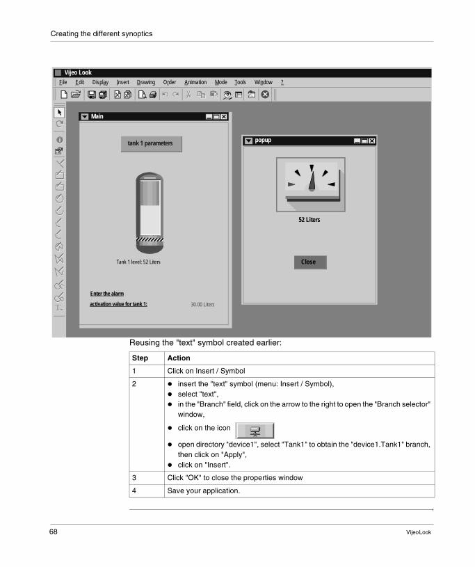
Reusing the "text" symbol created earlier:
i
Vijeo Look
Main
Tank 1 level: 52 Liters
tank 1 parameters
Enter the alarm
activation value for tank 1: 30.00 Liters
popup
52 Liters
Close
File Edit Display Insert Drawing Order Animation Mode Tools Window ?
Step Action
1 Click on Insert / Symbol
2 � insert the "text" symbol (menu: Insert / Symbol),� select "text", � in the "Branch" field, click on the arrow to the right to open the "Branch selector"
window,
� click on the icon
� open directory "device1", select "Tank1" to obtain the "device1.Tank1" branch, then click on "Apply",
� click on "Insert".
3 Click "OK" to close the properties window
4 Save your application.
68 Vijeo Look

Creating the different synoptics
Creating the "Web" synoptic
How do you create buttons?
Repeat the procedure in the previous (See How do you create buttons?, p. 66) chapter, replacing the "Tank 1 parameter" text with "www.telemecanique.com".
How do you create the "web" synoptic?
Using an ActiveX, a single click is all it takes to create a link in your project to an HTML page, an Internet site, etc.You will use the ActiveX interface in the IE browser supplied with Windows.
Step Action
1 Open a new synoptic and switch to "Edit" mode
2 Save the synoptic as "web"
3 From the "Tools" menu, choose "Ergonomics" then "ActiveX Control" to select the "Microsoft Web Browser" ActiveX, click "OK".
4 From the "Insert" menu, choose "Insert" then "ActiveX Control" and select "Microsoft Web Browser", click "OK".
5 Select the ActiveX, then right-click and choose "View the script "
6 key in the following code:Private Sub Mimic_Open ()
WebBrowser1.Navigate2 ("http://www.telemecanique.com")
End Sub
7 Resize the ActiveX to view the maximum amount of information
8 Save your project
9 Click on the "Execute" icon.
Vijeo Look 69

Creating the different synoptics
Viewing the trends, setpoints and alarms
Viewing the trends
The trend table is used to monitor data varations in real time. You do not need to create a trend table specially for tank 2; everything is represented in this view table.
View trends sample screen:
Step Action
1 Open the "main" synoptic
2 Insert the trend curves (Insert / Trend curve)
3 In the "Curves" tab, specify:� Label: tank1� Variable: @tank_lev_1.Tank_Level_1 (use the drop-down menu to select the
variable),� Line: color yellow,� Min: 0 and Max: 100
4 In the "Key" tab, double-click on "Minimum value" and "Maximum value". In the left-hand window, double-click on "0" in the "Size" column and enter 0 for the minimum value, and 100 for the maximum value.
5 In the "Display" tab, modify the display
6 Resize the table and save your changes.
View trends
00 12:27:00 12:28:00 12:29:00 12:30:
70 Vijeo Look

Creating the different synoptics
Viewing setpoints
A Log Viewer displays data saved via a special filter. The filter is attached to the Log Viewer when the latter is configured. You do not need to create a setpoint table specially for tank 2; everything is represented in this setpoint table.
View trends, setpoints and alarms sample screen:
Step Action
1 Open the "main" synoptic
2 Insert the setpoint controller (Insert / Log Viewer Control)
3 Double-click on the inserted object to access its properties
4 In the "Display" tab, modify the display
5 Resize the table and save your changes.
i
Vijeo Look
Main
Tank 1 level: 52 Liters
www.telemecanique.com tank 1 parameters
Enter the alarm
activation value for tank 1: 24.00 Liters
View trends
00 12:27:00 12:28:00 12:29:00 12:30:
View setpoints
Date Time Title Name Value29/10/200229/10/200229/10/200208/11/200208/11/200213/11/200213/11/2002
10:42:05:57811:41:30:57811:41:45:92116:32:53:93716:33:05:96810:37:13:75010:56:26:062
Change valueChange valueChange valueChange valueChange valueChange valueChange value
tank_lev_1 .Alarm....tank_lev_1 .Alarm....tank_lev_1 .Alarm....tank_lev_1 .Alarm....tank_lev_1 .Alarm....tank_lev_1 .Alarm....tank_lev_1 .Alarm....
12.0085.0010.0010.0082.0012.0024.00
View alarms
Date Time Title Name13/11/2002 09:42:50:015 Present alarm
acknowledgedtank_lev_1 .Alarm.tank_full
File Edit Display Insert Drawing Order Animation Mode Tools Window ?
Vijeo Look 71

Creating the different synoptics
Viewing alarms The Alarm Viewer is used to display and acknowledge alarms. The number of lines displayed depends on the size of the window and the selected font. Remember to configure alarm 2 for tank 2.Procedure to follow to create an Alarm Viewer:
Procedure to follow to create an alarm LED:
Inserting the "LED" symbol in the "Main" synoptic:
Step Action
1 Open the "main" synoptic
2 Insert the setpoint controller (Insert / Alarm Viewer Control)
3 Resize the table
4 Double-click on the Alarm Viewer to display its properties
5 To view the hidden configuration tabs, use the arrow buttons in the top right corner of the properties dialog box
6 Save your work.
Step Action
1 Draw an ellipse using the drawing tools
2 Open the properties window to assign it a "Reverse relief" appearance. Click "OK" to close the window
3 Right-click and choose Animation / Color / State
4 In the "State" field, enter "Full" then click "OK"
5 select the LED, then create a symbol. Call it: "LED" (this symbol will be used to create the alarm LED for tank 2),
6 Delete the previous symbol.
7 save your project.
Step Action
1 � menu: Insert / Symbol,� select "LED", � in the "Branch" field, click on the arrow to the right to open the "Branch selector"
window,
� click on the icon
� open directory "device1", select "Tank1" to obtain the "device1.Tank1" branch, then click on "Apply",
� click on "Insert".
2 Click "OK" to close the window
3 Save your application.
72 Vijeo Look

Creating the different synoptics
Conclusion
Executing my application
You have now finished the tutorial!All that's left to do is to execute the application (click on the "Execute" icon). Both tanks are working correctly, they are filled and emptied automatically. A counter follows the level of the tanks and an indicator light above the tanks flashes (in simulation mode). The field for entering the alarm activation threshold value has no effect on the indicator light; don't forget that we are in simulation mode. In real circumstances, the light would change color when the level of the tank reaches the threshold value.
If you click on the "Tank 1 parameters" or "Tank 2 parameters" buttons, a popup window will open. Similarly, if you click on the "www.telemecanique.com" button, the telemecanique Internet site will open in a popup window.
File Edit Display Insert Drawing Order Animation Mode Tools Window ?
i
Vijeo Look
Main
Tank 1 level: 52 Liters
www.telemecanique.com
Enter the alarm activation value for tank 1:
24.00 Liters
View trends
00 12:27:00 12:28:00 12:29:00 12:30:
View setpointsDate Time Title Name Value
29/10/200229/10/200229/10/200208/11/200208/11/200213/11/200213/11/200213/11/2002
10:42:05:57811:41:30:57811:41:45:92116:32:53:93716:33:05:96810:37:13:75010:56:26:06216:26:45:625
Change valueChange valueChange valueChange valueChange valueChange valueChange valueChange value
tank_lev_1 .Alarm....tank_lev_1 .Alarm....tank_lev_1 .Alarm....tank_lev_1 .Alarm....tank_lev_1 .Alarm....tank_lev_1 .Alarm....tank_lev_1 .Alarm....tank_lev_2 .Alarm....
12.0085.0010.0010.0082.0012.0024.0026.00
View alarmsDate Time Title Name
13/11/200213/11/2002
09:42:50:01509:42:50:015
Present alarm acknowledgedAlarme idle
tank_lev_1 .Alarm.tank_fulltank_lev_2 .Alarm.tank_full
tank 2 parameterstank 1 parameters
Enter the alarm activation value for tank 2:
90.00 Liters
Tank 2 level: 60 Liters
popup
52 Liters
Close
Vijeo Look 73

Creating the different synoptics
74 Vijeo Look
CBIndex
AActiveX, 23Alarm window, 24Alias
Creation, 31Edit, 29
BBean component, 23
DData server, 27
IInsert menu, 23
LLog server, 26Log window, 25
TTool Menu, 26trend curve, 24
Vijeo Look
VVijeo Look
Installation, 14License, 17Presentation, 10The tools, 22Uninstall, 16
75

Index
76
Vijeo Look