Embed Size (px)
Citation preview
VII - Finite State Machines © Copyright 2004, Gaetano Borriello and Randy H. Katz
1
Finite State Machines (FSM)
Sequential circuits primitive sequential elements combinational logic
Models for representing sequential circuits finite-state machines (Moore and Mealy)
Basic sequential circuits revisited shift registers counters
Design procedure state diagrams state transition table next state functions
Hardware description languages
VII - Finite State Machines © Copyright 2004, Gaetano Borriello and Randy H. Katz
2
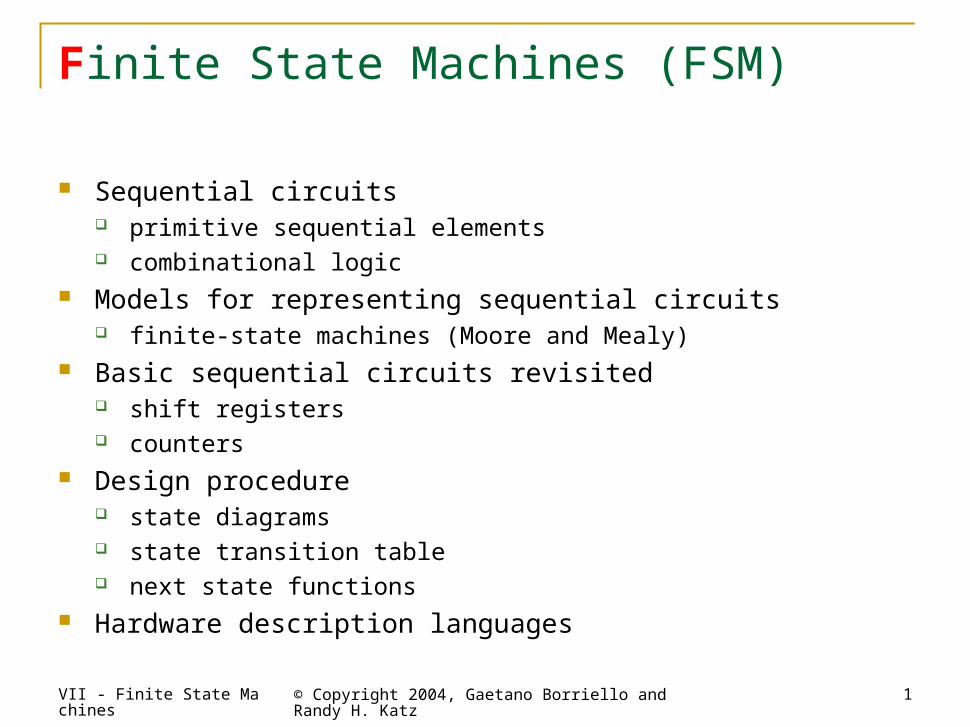
Abstraction of state elements
Divide circuit into combinational logic and state Localize the feedback loops and make it easy to break cycles Implementation of storage elements leads to various forms of sequential
logic
CombinationalLogic
Storage Elements
Outputs
State OutputsState Inputs
Inputs
VII - Finite State Machines © Copyright 2004, Gaetano Borriello and Randy H. Katz
3
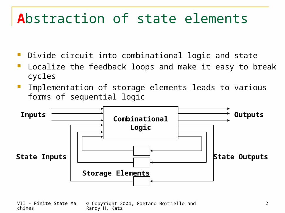
Forms of sequential logic
Asynchronous sequential logic – state changes occur whenever state inputs change (elements may be simple wires or delay elements)
Synchronous sequential logic – state changes occur in lock step across all storage elements (using clock)
Clock
VII - Finite State Machines © Copyright 2004, Gaetano Borriello and Randy H. Katz
4
In = 0
In = 1
In = 0In = 1
100
010
110
111001
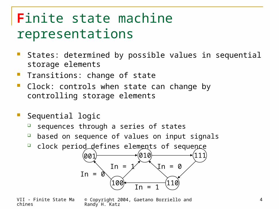
Finite state machine representations
States: determined by possible values in sequential storage elements
Transitions: change of state Clock: controls when state can change by controlling storage
elements
Sequential logic sequences through a series of states based on sequence of values on input signals clock period defines elements of sequence
VII - Finite State Machines © Copyright 2004, Gaetano Borriello and Randy H. Katz
5
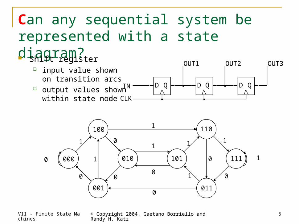
Can any sequential system be represented with a state diagram? Shift register
input value shownon transition arcs
output values shownwithin state node
100 110
111
011
101010000
001
1
1
1
1
0
0
00
1
1
1
0
0
1
00
D Q D Q D QIN
OUT1 OUT2 OUT3
CLK
VII - Finite State Machines © Copyright 2004, Gaetano Borriello and Randy H. Katz
6
010
100
110
011001
000
101111
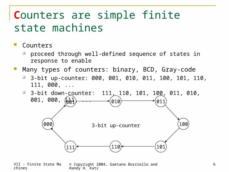
3-bit up-counter
Counters are simple finite state machines Counters
proceed through well-defined sequence of states in response to enable Many types of counters: binary, BCD, Gray-code
3-bit up-counter: 000, 001, 010, 011, 100, 101, 110, 111, 000, ... 3-bit down-counter: 111, 110, 101, 100, 011, 010, 001, 000, 111, ...
VII - Finite State Machines © Copyright 2004, Gaetano Borriello and Randy H. Katz
7
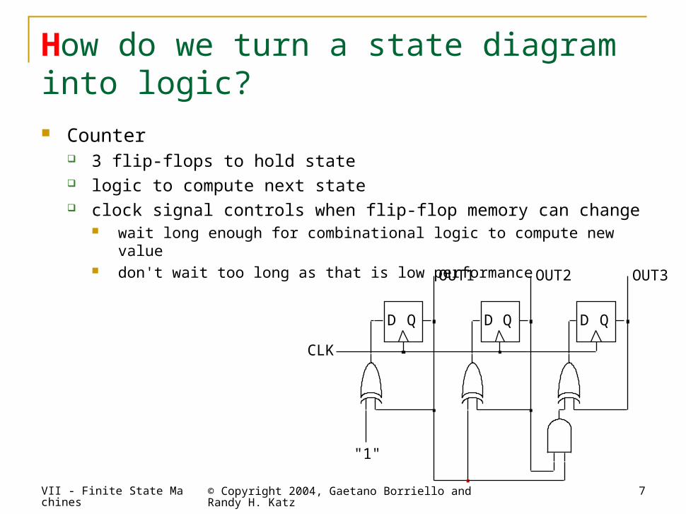
How do we turn a state diagram into logic? Counter
3 flip-flops to hold state logic to compute next state clock signal controls when flip-flop memory can change
wait long enough for combinational logic to compute new value don't wait too long as that is low performance
D Q D Q D Q
OUT1 OUT2 OUT3
CLK
"1"
VII - Finite State Machines © Copyright 2004, Gaetano Borriello and Randy H. Katz
8
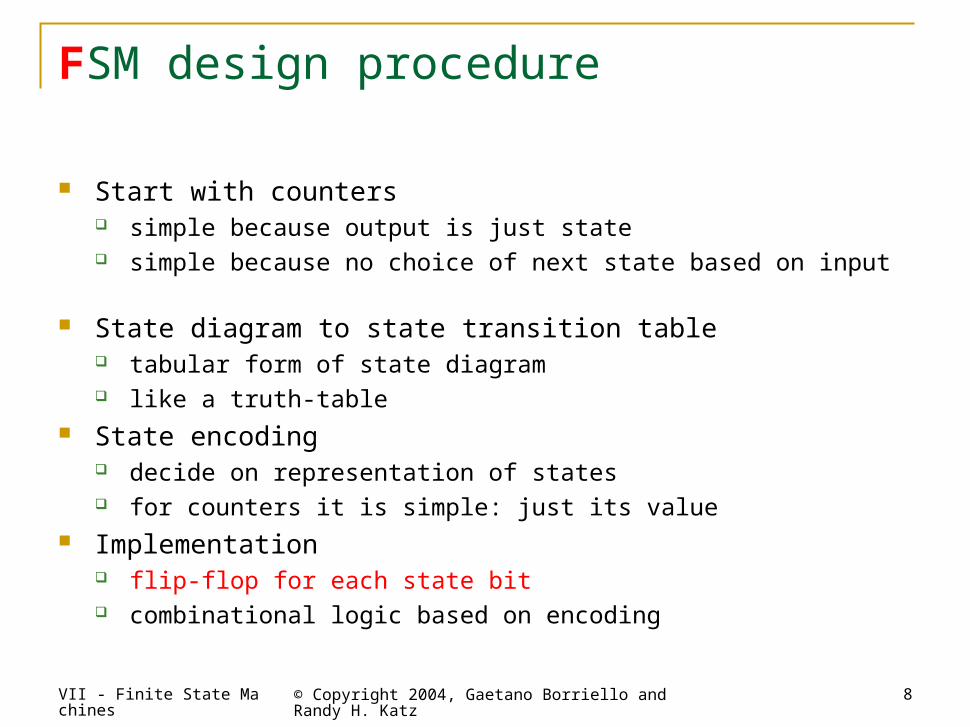
FSM design procedure
Start with counters simple because output is just state simple because no choice of next state based on input
State diagram to state transition table tabular form of state diagram like a truth-table
State encoding decide on representation of states for counters it is simple: just its value
Implementation flip-flop for each state bit combinational logic based on encoding
VII - Finite State Machines © Copyright 2004, Gaetano Borriello and Randy H. Katz
9
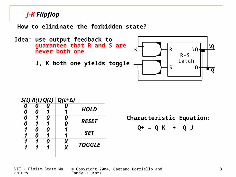
J-K Flipflop
How to eliminate the forbidden state?
Idea: use output feedback to guarantee that R and S are never both one
J, K both one yields toggle
Characteristic Equation:
Q+ = Q K + Q J
R-S latch
K
J S
R
Q
\ Q \ Q
Q
S(t)00001111
R(t)00110011
Q(t)01010101
Q(t+∆)010011XX
HOLD
RESET
SET
TOGGLE
VII - Finite State Machines © Copyright 2004, Gaetano Borriello and Randy H. Katz
10
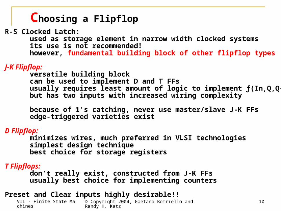
Choosing a FlipflopR-S Clocked Latch: used as storage element in narrow width clocked systems its use is not recommended! however, fundamental building block of other flipflop types
J-K Flipflop: versatile building block can be used to implement D and T FFs usually requires least amount of logic to implement ƒ(In,Q,Q+) but has two inputs with increased wiring complexity
because of 1's catching, never use master/slave J-K FFs edge-triggered varieties exist
D Flipflop: minimizes wires, much preferred in VLSI technologies simplest design technique best choice for storage registers
T Flipflops: don't really exist, constructed from J-K FFs usually best choice for implementing counters
Preset and Clear inputs highly desirable!!
VII - Finite State Machines © Copyright 2004, Gaetano Borriello and Randy H. Katz
11
010
100
110
011001
000
101111
3-bit up-counter
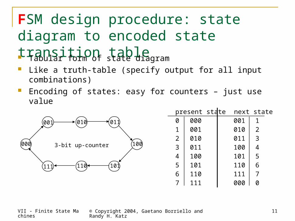
present state next state0 000 001 11 001 010 22 010 011 33 011 100 44 100 101 55 101 110 66 110 111 77 111 000 0
FSM design procedure: state diagram to encoded state transition table Tabular form of state diagram Like a truth-table (specify output for all input combinations) Encoding of states: easy for counters – just use value
VII - Finite State Machines © Copyright 2004, Gaetano Borriello and Randy H. Katz
12
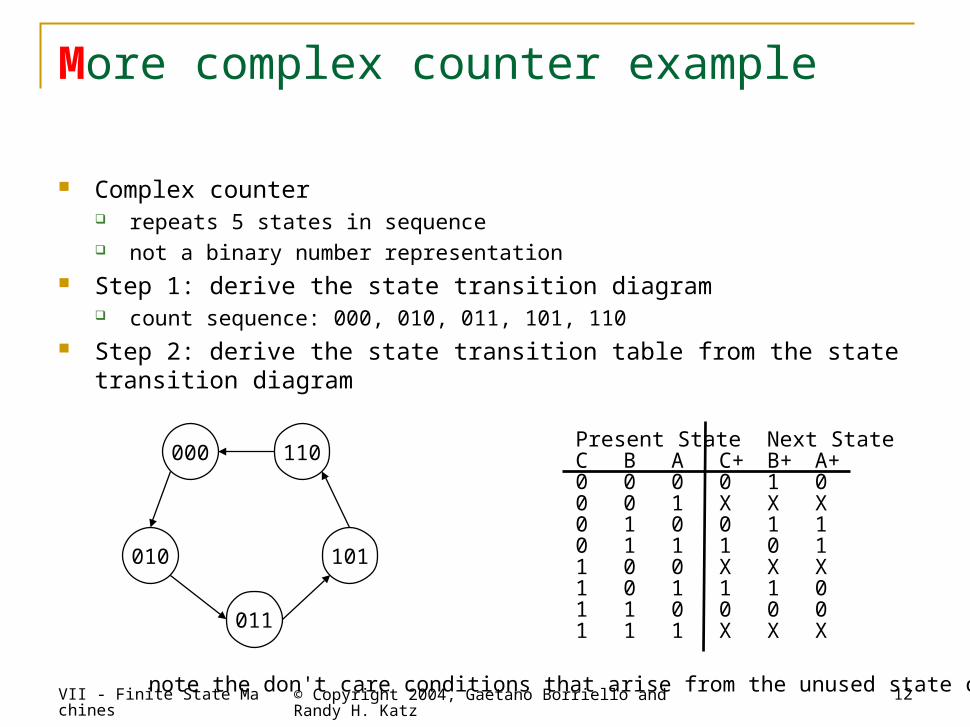
More complex counter example
Complex counter repeats 5 states in sequence not a binary number representation
Step 1: derive the state transition diagram count sequence: 000, 010, 011, 101, 110
Step 2: derive the state transition table from the state transition diagram
Present StateNext StateC B A C+ B+ A+0 0 0 0 1 00 0 1 X X X0 1 0 0 1 10 1 1 1 0 11 0 0 X X X1 0 1 1 1 01 1 0 0 0 01 1 1 X X X
note the don't care conditions that arise from the unused state codes
010
000 110
101
011
VII - Finite State Machines © Copyright 2004, Gaetano Borriello and Randy H. Katz
13
010
000 110
101
011
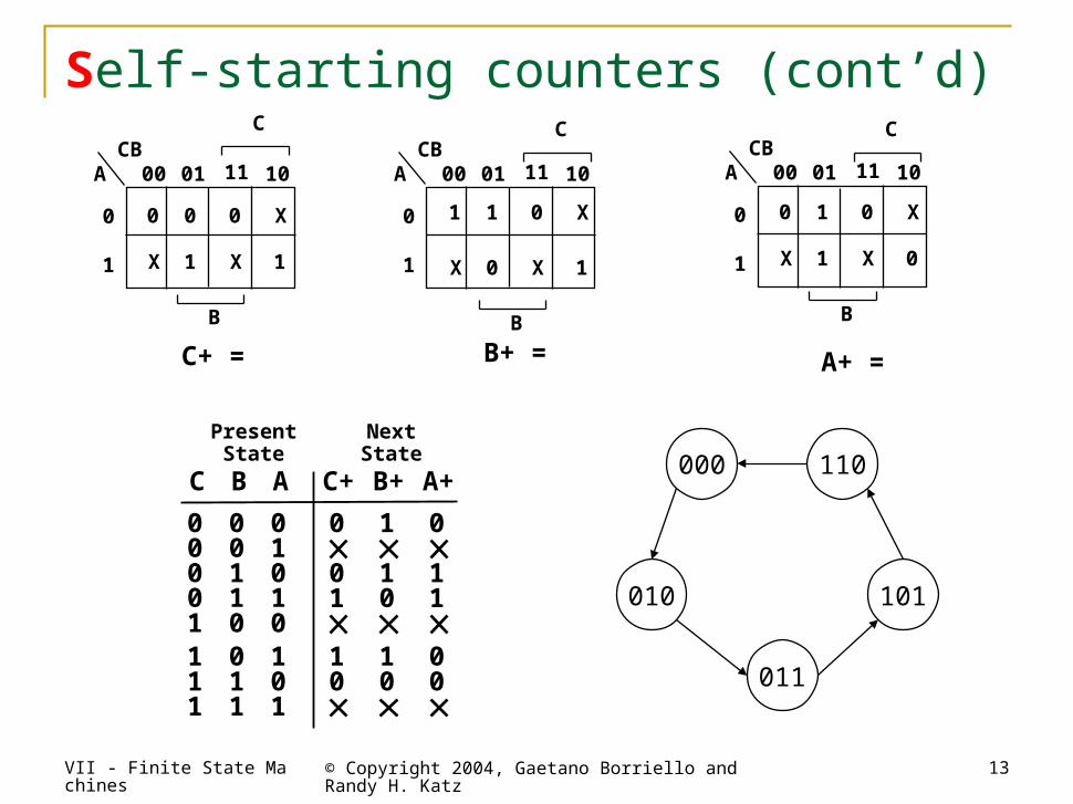
Self-starting counters (cont’d)
1
PresentState
NextState
C B A C+ B+
1
A+
0 0 00 00 00
0 00
0
11 1
11 11 11 1 1
0 0
00
00 0 0
1 11 1
1 1
CB00 01 11 10A
0
1
C+ =
CB00 01 11 10A
0
1
A+ =
CB00 01 11 10A
0
1
B+ =
0 0 0
0
0 0
0
0
11
1 1
1 1
1
X X
X
X X
X X
XX
C C C
B B B
VII - Finite State Machines © Copyright 2004, Gaetano Borriello and Randy H. Katz
14
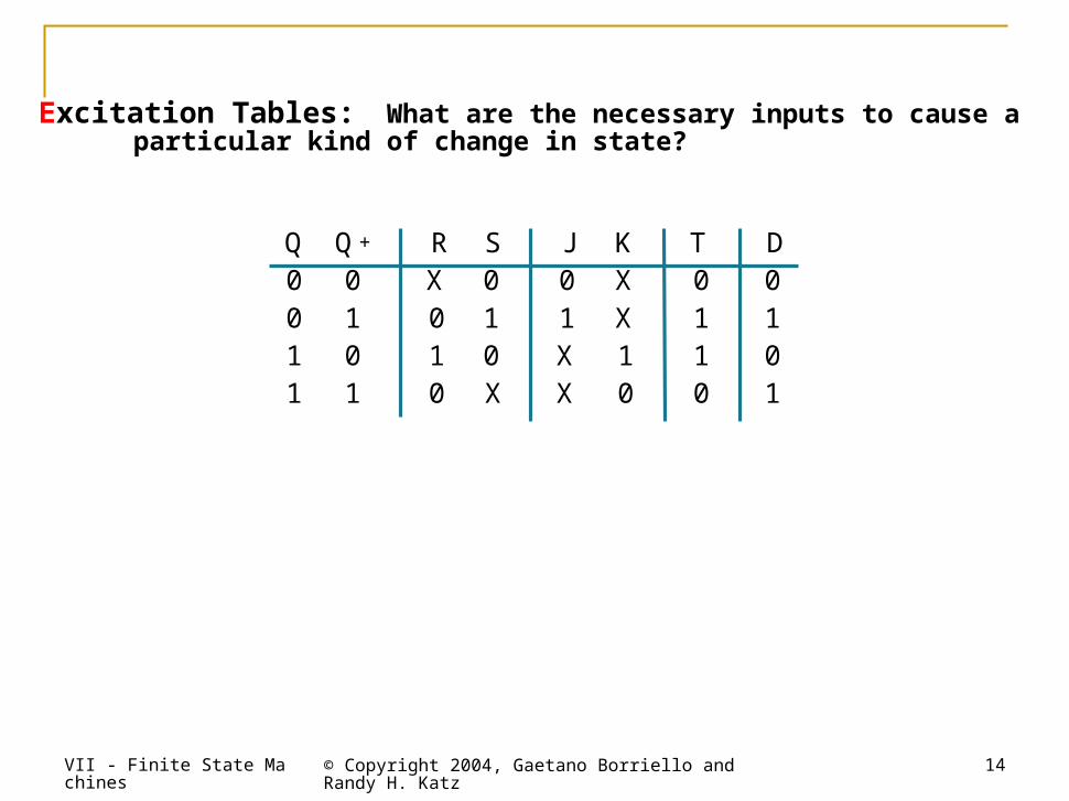
Excitation Tables: What are the necessary inputs to cause a particular kind of change in state?
D 0 1 0 1
T 0 1 1 0
Q + 0 1 0 1
Q 0 0 1 1
S 0 1 0 X
R X 0 1 0
K X X 1 0
J 0 1 X X
VII - Finite State Machines © Copyright 2004, Gaetano Borriello and Randy H. Katz
15
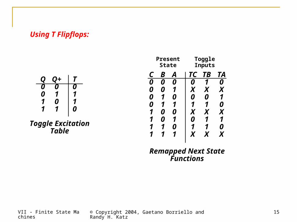
Toggle ExcitationTable
Remapped Next StateFunctions
Q0011
Q+0101
T0110
PresentState
ToggleInputs
C00001111
B00110011
A01010101
TC0X01X01X
TB1X01X11X
TA0X10X10X
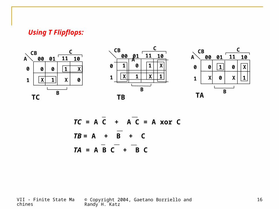
Using T Flipflops:
VII - Finite State Machines © Copyright 2004, Gaetano Borriello and Randy H. Katz
16
TC = A C + A C = A xor C
TB = A + B + C
TA = A B C + B C
CB00 01 11 10A
0
1
TC
CB00 01 11 10A
0
1
TA
CB00 01 11 10
A0
1
TB
0 0
0
0 0 0
01
11
1
1
1
1
1X
X
XX X
X
X X
X
CC C
BB B
Using T Flipflops:
VII - Finite State Machines © Copyright 2004, Gaetano Borriello and Randy H. Katz
17
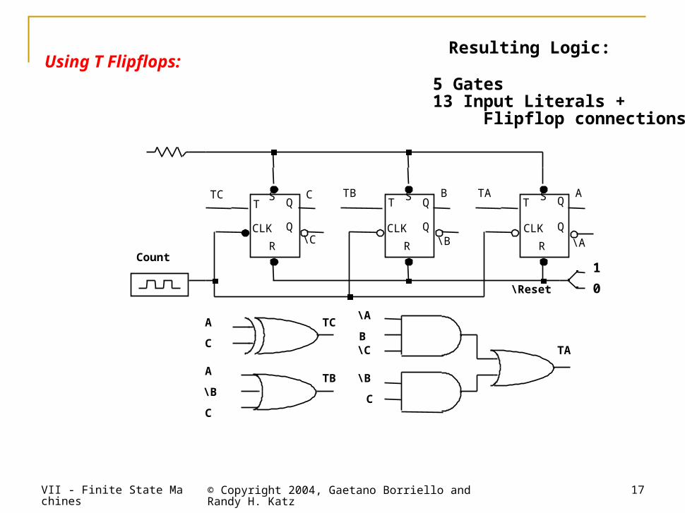
Resulting Logic:
5 Gates13 Input Literals + Flipflop connections
TCT
CLK
Q
Q
S
RCount
T
CLK
Q
Q
S
R
TBC
\C
B A
\B \A
TAT
CLK
Q
Q
S
R
\Reset
1
0
A
C
A
\B
C
TC
TB
\A
B\C
\B
C
TA
Using T Flipflops:
VII - Finite State Machines © Copyright 2004, Gaetano Borriello and Randy H. Katz
18
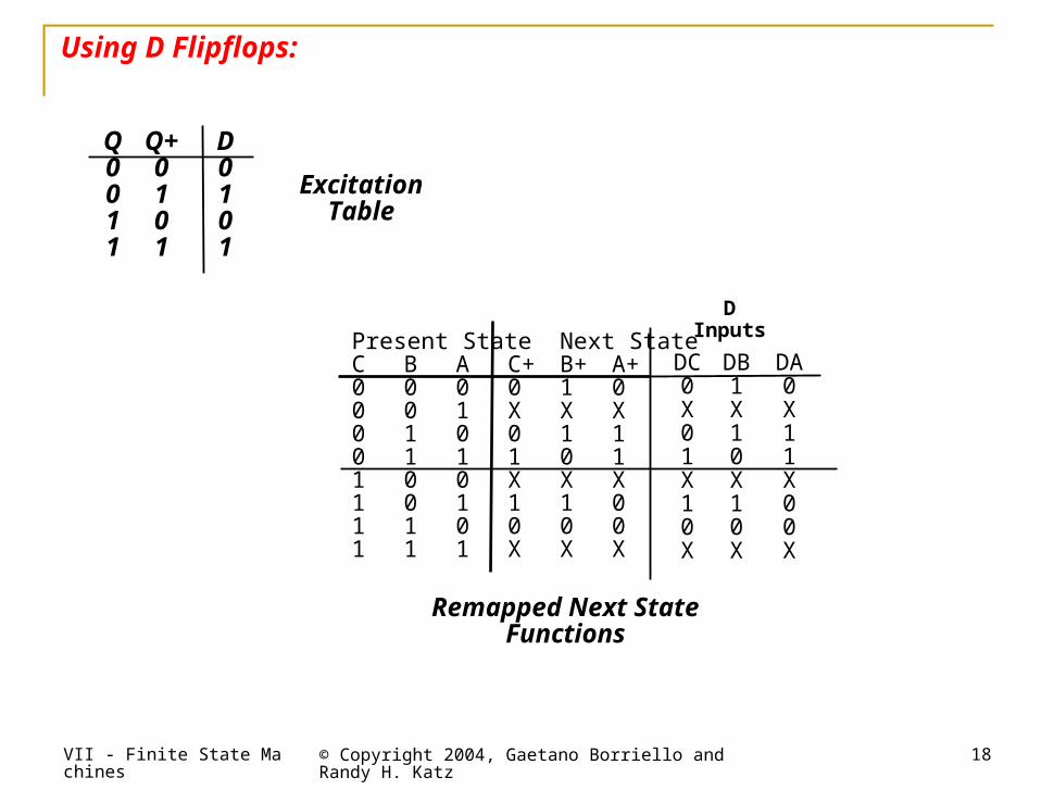
ExcitationTable
Remapped Next StateFunctions
Q0011
Q+0101
D0101
Using D Flipflops:
DInputs
DC0X01X10X
DB1X10X10X
DA0X11X00X
Present StateNext StateC B A C+ B+ A+0 0 0 0 1 00 0 1 X X X0 1 0 0 1 10 1 1 1 0 11 0 0 X X X1 0 1 1 1 01 1 0 0 0 01 1 1 X X X
VII - Finite State Machines © Copyright 2004, Gaetano Borriello and Randy H. Katz
19
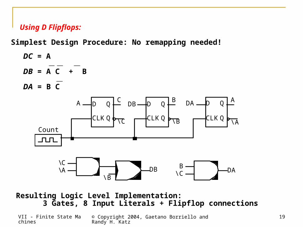
Simplest Design Procedure: No remapping needed!
DC = A
DB = A C + B
DA = B C
Resulting Logic Level Implementation: 3 Gates, 8 Input Literals + Flipflop connections
CLK CLK
D Q
Q
A
\ A
D Q
Q
DA DB B
\ B CLK
D Q
Q
A C
\ C Count
\ C \ A
\ B
B \ C DA DB
Using D Flipflops:
VII - Finite State Machines © Copyright 2004, Gaetano Borriello and Randy H. Katz
20
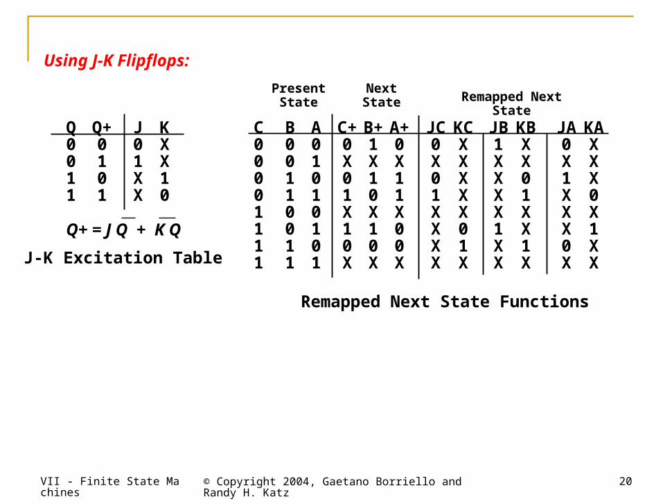
J-K Excitation Table
Remapped Next State Functions
Q+ = J Q + K QQ+ = J Q + K Q
Q0011
Q+0101
J01XX
KXX10
PresentState
NextState Remapped Next State
C00001111
B00110011
A01010101
C+0X01X10X
B+1X10X10X
A+0X11X00X
JC0X01XXXX
KCXXXXX01X
JB1XXXX1XX
KBXX01XX1X
JA0X1XXX0X
KAXXX0X1XX
Using J-K Flipflops:
VII - Finite State Machines © Copyright 2004, Gaetano Borriello and Randy H. Katz
21
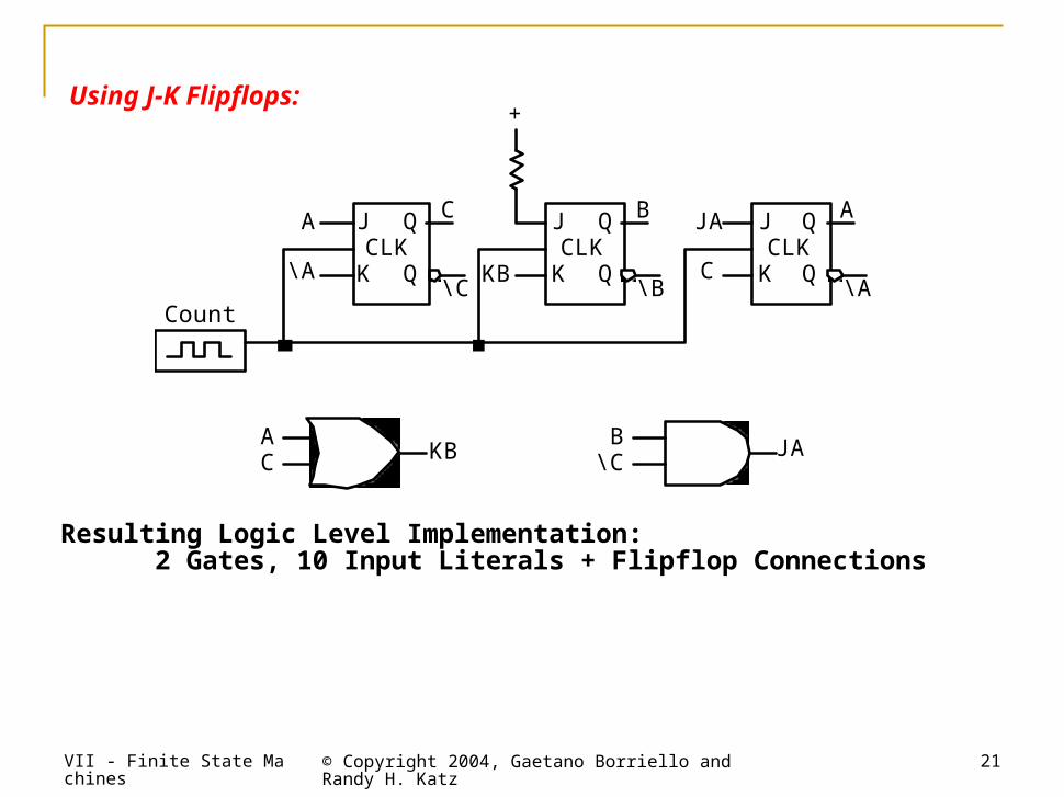
Resulting Logic Level Implementation: 2 Gates, 10 Input Literals + Flipflop Connections
CLK CLK CLK J
K
Q
Q
A
\ A
C
\ C KB
J
K
Q
Q
B
\ B
+
J
K
Q
Q
JA
C
A
\ A
B \ C
Count
A C KB JA
Using J-K Flipflops:
VII - Finite State Machines © Copyright 2004, Gaetano Borriello and Randy H. Katz
22
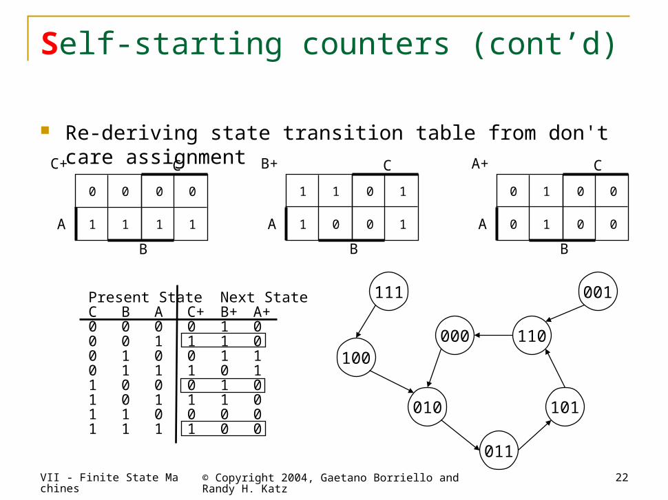
Self-starting counters (cont’d)
Re-deriving state transition table from don't care assignment
0 0
1 1
0 0
1 1A
B
CC+
1 1
1 0
0 1
0 1A
B
CB+
0 1
0 1
0 0
0 0A
B
CA+
Present StateNext StateC B A C+ B+ A+0 0 0 0 1 00 0 1 1 1 00 1 0 0 1 10 1 1 1 0 11 0 0 0 1 01 0 1 1 1 01 1 0 0 0 01 1 1 1 0 0
010
000 110
101
011
001111
100
VII - Finite State Machines © Copyright 2004, Gaetano Borriello and Randy H. Katz
23
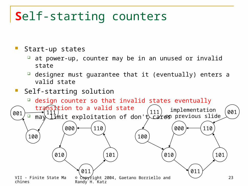
Self-starting counters
Start-up states at power-up, counter may be in an unused or invalid state designer must guarantee that it (eventually) enters a valid state
Self-starting solution design counter so that invalid states eventually transition to a valid state may limit exploitation of don't cares
implementationon previous slide
010
000 110
101
011
001111
100
010
000 110
101
011
001 111
100
VII - Finite State Machines © Copyright 2004, Gaetano Borriello and Randy H. Katz
24
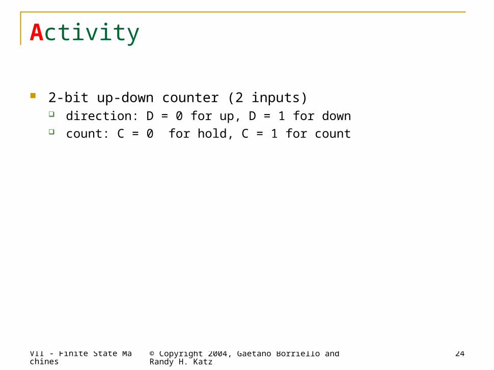
Activity
2-bit up-down counter (2 inputs) direction: D = 0 for up, D = 1 for down count: C = 0 for hold, C = 1 for count
01
00 11
10
C=0D=X
C=0D=X
C=0D=X
C=0D=X
C=1D=0
C=1D=0
C=1D=0
C=1D=0
C=1D=1
S1 S0 C D N1 N00 0 0 0 0 00 0 0 1 0 00 0 1 0 0 10 0 1 1 1 10 1 0 0 0 10 1 0 1 0 10 1 1 0 1 00 1 1 1 0 01 0 0 0 1 01 0 0 1 1 01 0 1 0 1 11 0 1 1 0 11 1 0 0 1 11 1 0 1 1 11 1 1 0 0 01 1 1 1 1 0
VII - Finite State Machines © Copyright 2004, Gaetano Borriello and Randy H. Katz
25
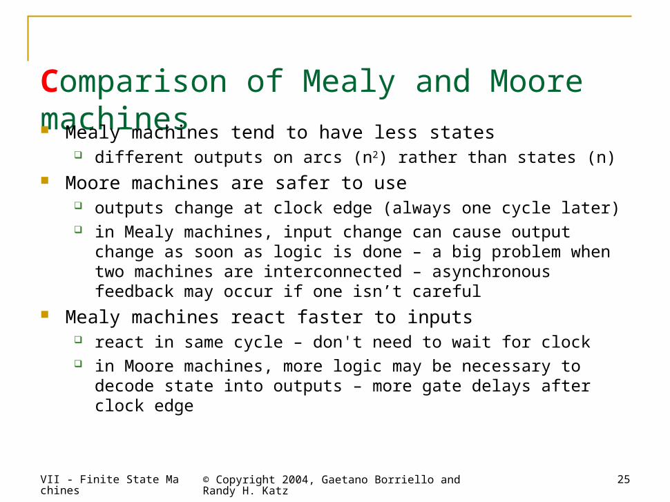
Comparison of Mealy and Moore machines Mealy machines tend to have less states
different outputs on arcs (n2) rather than states (n) Moore machines are safer to use
outputs change at clock edge (always one cycle later) in Mealy machines, input change can cause output change as soon as
logic is done – a big problem when two machines are interconnected – asynchronous feedback may occur if one isn’t careful
Mealy machines react faster to inputs react in same cycle – don't need to wait for clock in Moore machines, more logic may be necessary to decode state into
outputs – more gate delays after clock edge
VII - Finite State Machines © Copyright 2004, Gaetano Borriello and Randy H. Katz
26
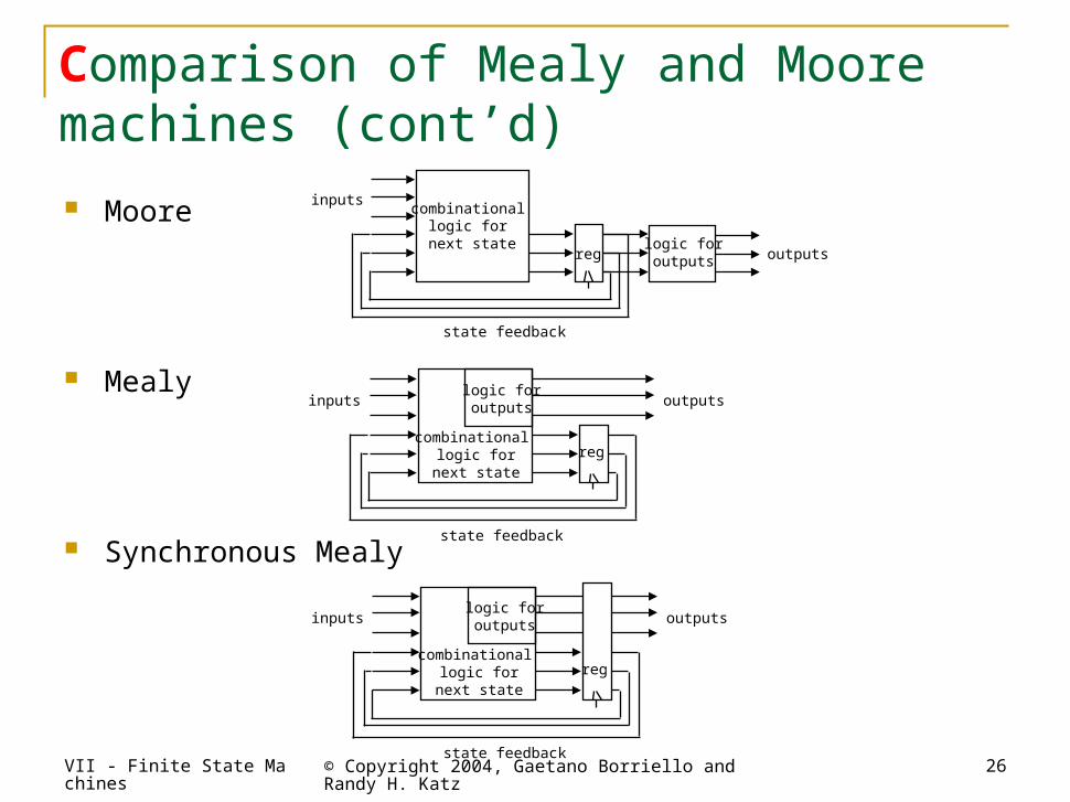
Comparison of Mealy and Moore machines (cont’d)
Moore
Mealy
Synchronous Mealy
state feedback
inputs
outputsreg
combinational logic for
next state logic foroutputs
inputs outputs
state feedback
regcombinational
logic fornext state
logic foroutputs
inputs outputs
state feedback
regcombinational
logic fornext state
logic foroutputs
VII - Finite State Machines © Copyright 2004, Gaetano Borriello and Randy H. Katz
27
D/1
E/1
B/0
A/0
C/0
1
0
0
00
1
1
1
1
0
reset
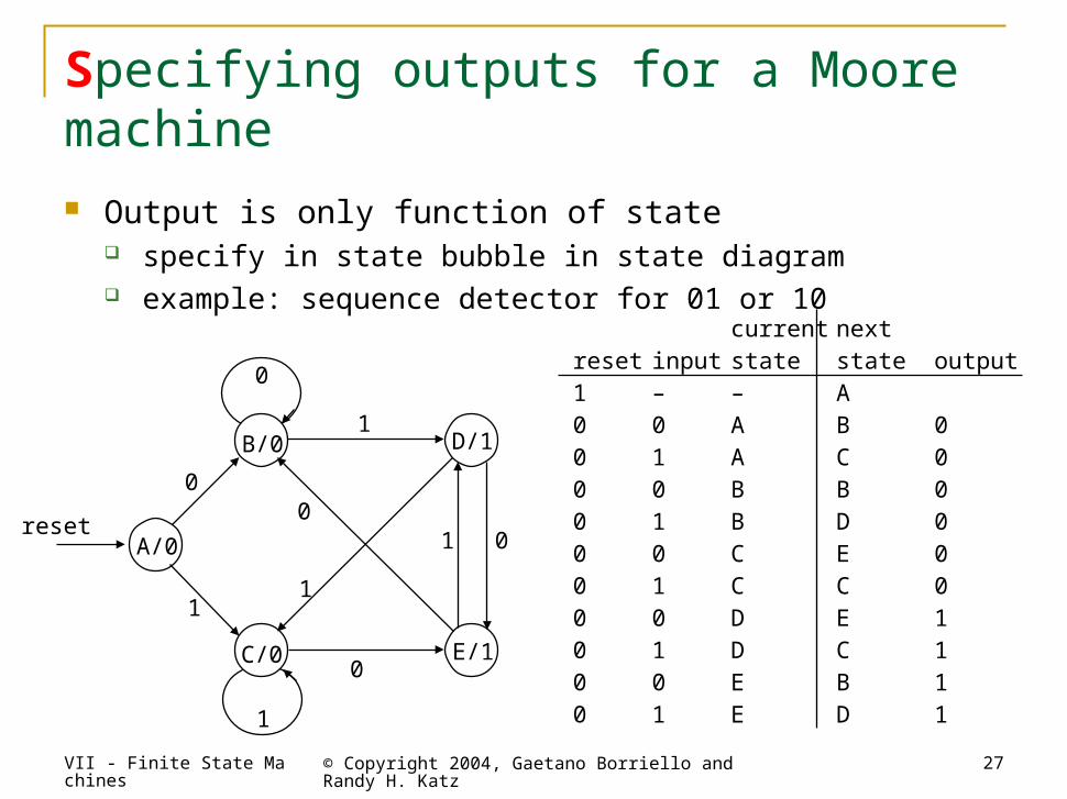
current nextreset input state state output1 – – A0 0 A B 00 1 A C 00 0 B B 00 1 B D 00 0 C E 00 1 C C 00 0 D E 10 1 D C 10 0 E B 10 1 E D 1
Specifying outputs for a Moore machine Output is only function of state
specify in state bubble in state diagram example: sequence detector for 01 or 10
VII - Finite State Machines © Copyright 2004, Gaetano Borriello and Randy H. Katz
28
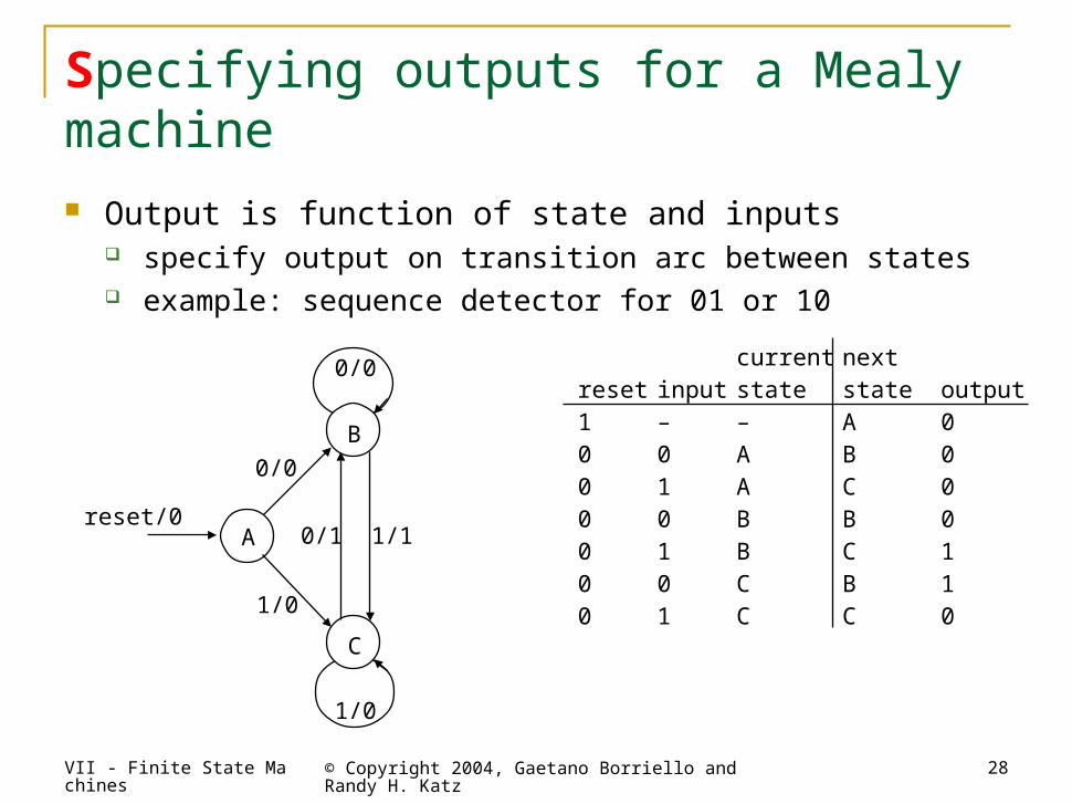
current nextreset input state state output1 – – A 00 0 A B 00 1 A C 00 0 B B 00 1 B C 10 0 C B 10 1 C C 0
B
A
C
0/1
0/0
0/0
1/1
1/0
1/0
reset/0
Specifying outputs for a Mealy machine Output is function of state and inputs
specify output on transition arc between states example: sequence detector for 01 or 10
VII - Finite State Machines © Copyright 2004, Gaetano Borriello and Randy H. Katz
29
VendingMachine
FSM
N
D
Reset
Clock
OpenCoinSensor
ReleaseMechanism
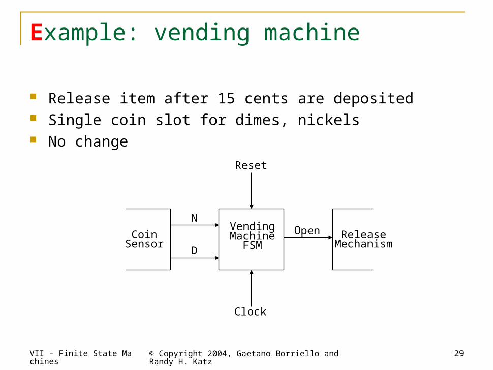
Example: vending machine
Release item after 15 cents are deposited Single coin slot for dimes, nickels No change
VII - Finite State Machines © Copyright 2004, Gaetano Borriello and Randy H. Katz
30
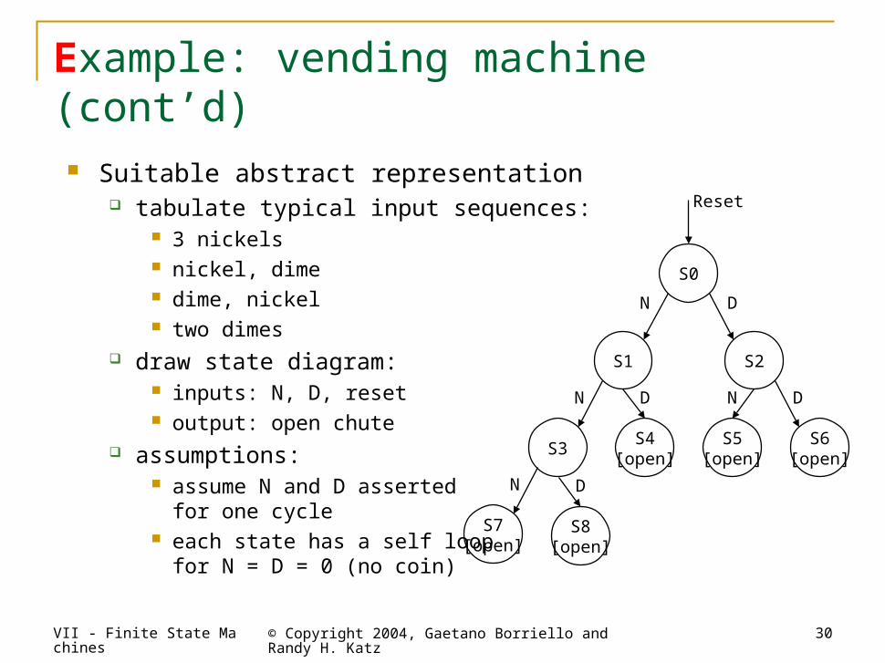
Example: vending machine (cont’d)
Suitable abstract representation tabulate typical input sequences:
3 nickels nickel, dime dime, nickel two dimes
draw state diagram: inputs: N, D, reset output: open chute
assumptions: assume N and D asserted
for one cycle each state has a self loop
for N = D = 0 (no coin)
S0
Reset
S2
D
S6[open]
D
S4[open]
D
S1
N
S3
N
S5[open]
N
S8[open]
D
S7[open]
N
VII - Finite State Machines © Copyright 2004, Gaetano Borriello and Randy H. Katz
31
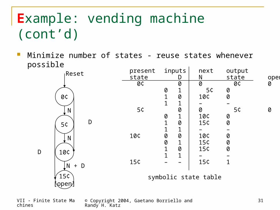
Example: vending machine (cont’d)
Minimize number of states - reuse states whenever possible
symbolic state table
present inputs next outputstate D N state open 0¢ 0 0 0¢ 0
0 1 5¢ 01 0 10¢ 01 1 – –
5¢ 0 0 5¢ 00 1 10¢ 01 0 15¢ 01 1 – –
10¢ 0 0 10¢ 00 1 15¢ 01 0 15¢ 01 1 – –
15¢ – – 15¢ 1
0¢
Reset
5¢
N
N
N + D
10¢
D
15¢[open]
D
VII - Finite State Machines © Copyright 2004, Gaetano Borriello and Randy H. Katz
32
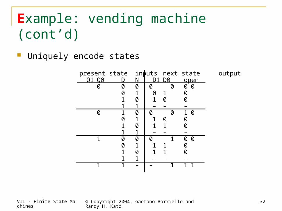
present stateinputs next state outputQ1 Q0 D N D1 D0 open
0 0 0 0 0 0 00 1 0 1 01 0 1 0 01 1 – – –
0 1 0 0 0 1 00 1 1 0 01 0 1 1 01 1 – – –
1 0 0 0 1 0 00 1 1 1 01 0 1 1 01 1 – – –
1 1 – – 1 1 1
Example: vending machine (cont’d)
Uniquely encode states
VII - Finite State Machines © Copyright 2004, Gaetano Borriello and Randy H. Katz
33
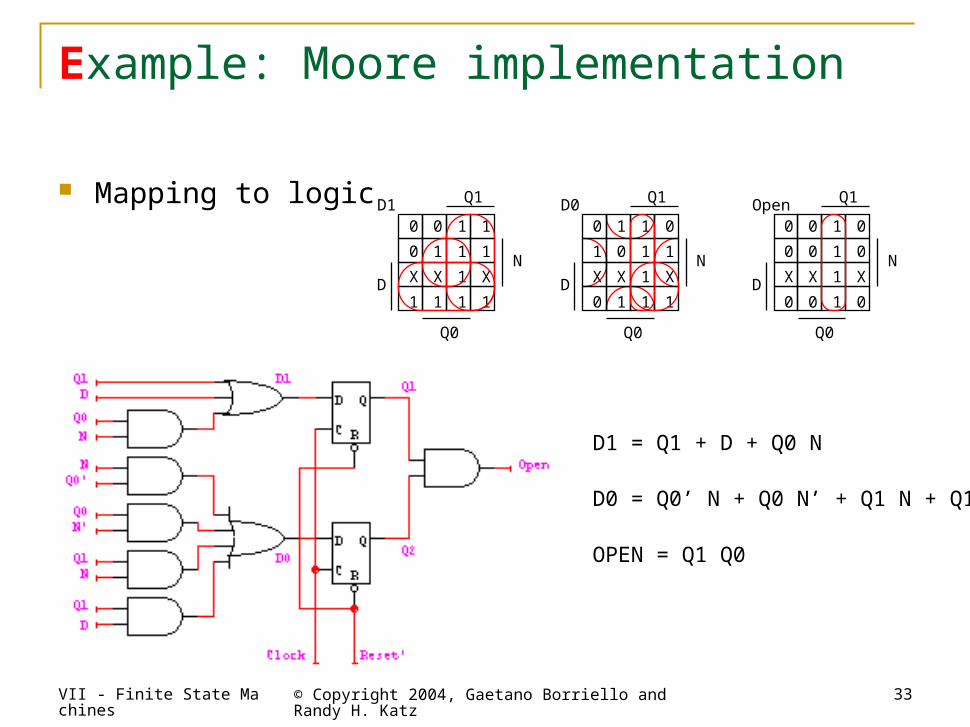
D1 = Q1 + D + Q0 N
D0 = Q0’ N + Q0 N’ + Q1 N + Q1 D
OPEN = Q1 Q0
Example: Moore implementation
Mapping to logic0 0 1 1
0 1 1 1
X X 1 X
1 1 1 1
Q1D1
Q0
N
D
0 1 1 0
1 0 1 1
X X 1 X
0 1 1 1
Q1D0
Q0
N
D
0 0 1 0
0 0 1 0
X X 1 X
0 0 1 0
Q1Open
Q0
N
D
VII - Finite State Machines © Copyright 2004, Gaetano Borriello and Randy H. Katz
34
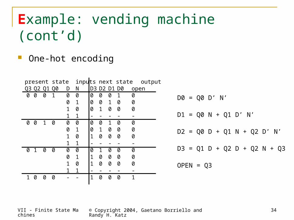
present state inputs next state outputQ3Q2 Q1Q0 D N D3 D2 D1 D0 open0 0 0 1 0 0 0 0 0 1 0
0 1 0 0 1 0 01 0 0 1 0 0 01 1 - - - - -
0 0 1 0 0 0 0 0 1 0 00 1 0 1 0 0 01 0 1 0 0 0 01 1 - - - - -
0 1 0 0 0 0 0 1 0 0 00 1 1 0 0 0 01 0 1 0 0 0 01 1 - - - - -
1 0 0 0 - - 1 0 0 0 1
D0 = Q0 D’ N’
D1 = Q0 N + Q1 D’ N’
D2 = Q0 D + Q1 N + Q2 D’ N’
D3 = Q1 D + Q2 D + Q2 N + Q3
OPEN = Q3
Example: vending machine (cont’d)
One-hot encoding
VII - Finite State Machines © Copyright 2004, Gaetano Borriello and Randy H. Katz
35
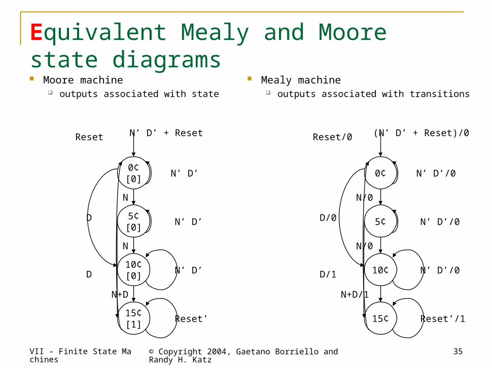
Equivalent Mealy and Moore state diagrams Moore machine
outputs associated with state
0¢[0]
10¢[0]
5¢[0]
15¢[1]
N’ D’ + Reset
D
D
N
N+D
N
N’ D’
Reset’
N’ D’
N’ D’
Reset
0¢
10¢
5¢
15¢
(N’ D’ + Reset)/0
D/0
D/1
N/0
N+D/1
N/0
N’ D’/0
Reset’/1
N’ D’/0
N’ D’/0
Reset/0
Mealy machine outputs associated with transitions