Embed Size (px)
Citation preview
Mechanical Technical Report Three
McKinstry Oregon HeadquartersAlex Wyczalkowski November 21, 2008
Prepared forDr. Jelena Srebric, Ph.D.Associate Professor of Architectural EngineeringThe Pennsylvania State University

T e c h n i c a l R e p o r t 3 P a g e | 2
Table of Contents
1 Executive Summary 3
2 Building and Mechanical System Overview 4
3 Design Objectives and Requirements 6
4 Energy Sources and Rates 7
5 Site Factors and Design Conditions 75.1 Site Factors 75.2 Rebates and Tax Incentives 85.3 Design Conditions 8
6 Ventilation Requirements 9
7 Heating and Cooling Loads 9
8 Annual Energy Use 10
9 Mechanical System Schematic Drawings 11
10 Major Equipment 12
11 System Operation Description 1411.1 Air Handling Unit 1411.2 Fan Terminal Units 1511.3 Heat Recovery Chiller and Well System 15
12 Mechanical System First Cost and Lost Space 16
13 Mechanical LEED Analysis 1713.1 Energy and Atmosphere Credit 1 1713.2 Other LEED Credits 19
14 Overall Evaluation of System 20
15 References 21
16 Appendix A: Portland Design Conditions 22
17 Appendix B: System Cost Breakdown 23
18 Appendix C: LEED Project Checklist 24
A l e x W y c z a l k o w s k i M c K i n s t r y O r e g o n H e a d q u a r t e r s

T e c h n i c a l R e p o r t 3 P a g e | 3
1 Executive SummaryMcKinstry Oregon Headquarters is a 50,590 square foot, 2 story office building. It began
construction in March 2008 and is scheduled for completion in March 2009. It is located in
Northeast Portland, overlooking the Columbia River. The building contains 2 floors of offices, as
well as a full kitchen, showers, and a small weight room for employees. There is also a large
warehouse at the west end of the building which is not ventilated.
The design of the Headquarters was dictated by three main factors: sustainability, comfort for
tenants, and economy. Section 3 describes how each of these three factors needed to be balanced
to make the building work well.
LEED Certification was very prominent in the design of the building as well. In Section 5.2
shows tax credits totaling over $600,000 that can be achieved by a green building in Oregon.
This value is a large incentive to push sustainability and energy efficiency.
The tax credits may be desperately needed for McKinstry. Based on the proposed energy model
(Section 8) compared to the ASHRAE baseline model (Section 13), and large upfront costs of the
premium system (Section 12), there isn’t a large change in energy savings. However, Section 13
also discusses possible errors in the models that could attribute for the small savings.
Detailed descriptions of building systems and operations can be found in Sections 2 (Overview
of systems), Section 9 (Schematic Drawings), Section 10 (Mechanical Equipment), Section 11
(System Operation), and Section 12 (First Cost and Lost Space). First cost for the mechanical
system is $1,394,511.
A l e x W y c z a l k o w s k i M c K i n s t r y O r e g o n H e a d q u a r t e r s

T e c h n i c a l R e p o r t 3 P a g e | 4
2 Building and Mechanical System OverviewMcKinstry Oregon Headquarters is a $15.5 million project which is scheduled for completion
March 1, 2009. This includes two buildings. The only building of interest is the office building,
as the other is simply a warehouse. Costs for the 50,590 square foot office building total $11.1
million dollars.
The headquarters is a 2 story office building. The office is laid out in a simple rectangular grid.
At the West end of the building a full height 1 story warehouse attaches at a rotated angle.
Figure 2.1. Building Footprint
The flat, tilt-up concrete walls have vertical and horizontal lines to break the long straight façade.
Approximately 30% of the office façade is glazing and windows are double glazed. The base of
the building is a reinforced concrete slab (there is no basement). The exterior walls are backed
by 3-5/8” metal studs and 3.5” batt insulation. A built-up roof with 3” rigid insulation and 1.5”
metal decking tops off the structure. The roof also has several translucent skylights for natural
day lighting. The remaining lighting in the building is fairly standard with 100% fluorescent
fixtures.
A l e x W y c z a l k o w s k i M c K i n s t r y O r e g o n H e a d q u a r t e r s
Office23,000 sfper floor
WareHouse4400
sfVestibule 484 sf
N
T e c h n i c a l R e p o r t 3 P a g e | 5
Figure 2.2. Waterside system, shown in heating mode. (McKinstry Design Documents)
The central plant of the building is a heat recovery chiller that is used for both heating and
cooling. The mechanical system also includes an open loop ground source heat pump. Ground
water accepts heat from the condensing water in cooling mode and provides heat to the
evaporator water in heating mode. Evaporator side water and condenser side water are piped to
the cooling and heating coils in the air handling unit, respectively. A single rooftop AHU (with
VFD) distributes air via ducts to the office section of the building. Series VAV boxes with hot
water reheats are located throughout the office. Also, an airside economizer can provide cooling
on light load days. Two hot water unit heaters keep the warehouse warm in the winter. Heating
is provided by the hot water loop and there is no cooling or ventilation. Linear diffusers
condition the vestibule at the front of the building. More details can be found in Section 9.
A l e x W y c z a l k o w s k i M c K i n s t r y O r e g o n H e a d q u a r t e r s

T e c h n i c a l R e p o r t 3 P a g e | 6
3 Design Objectives and RequirementsMany factors go into the design of a mechanical system. Before choosing the correct system, a
designer must first know what are the owner’s and occupant’s needs. In the McKinstry Oregon
Headquarters, it is a combination of sustainability, comfort, and economy.
First and foremost, the McKinstry wanted to make sure their new building received LEED
Certification. According to McKinstry designers, LEED has become the industry standard.
Achieving certification is seen no longer as a perk, but a necessity. At the beginning of design,
McKinstry looked into several sustainable solutions. One of which was on-site wind energy or
solar energy. The designers also wanted to save water by harvesting rainwater. This grey water
would supply all of the toilets and urinals in the building. The mechanical system is an open
loop ground source heat pump. In a metaphorical way, the open loop system, like the roots of a
tree, gets its energy from the earth. This can provide substantial savings on energy. Finally,
being a mechanical company, they find an aesthetic to their work and chose to leave the
ductwork exposed throughout the building.
Tenants’ comfort was very important from the beginning of design. A comfortable employee is
a more productive employee, so the designers wanted to make sure every effort was taken to
maintain a comfortable environment inside the building. On the mechanical side, indoor
temperatures were set to very comfortable temperatures (70ºF in the winter and 74ºF in the
summer). Some buildings in the Portland area would actually raise their summer setpoint to as
high as 80ºF to save energy. Windows in the room were placed higher on the walls to decrease
direct sunlight onto the work plane. The building also includes a full kitchen with stove and
hood system, showers for those who bike to work, and a weight room. All of this creates a
welcome atmosphere to employees and encourages employees to spend time together on breaks.
Finally, just as in virtually any project, hard dollars step in and dictate which ideas are feasible
and which ideas are pipe dreams. Throughout the project, total costs dwindled from about $20
million to $15 million. Several ideas such as solar and wind power were scrapped (the wind
power had a 30+ year payback). Rainwater harvesting was reduced from supplying all the toilet
grey water to being a supplemental system. As with any building, the greatest challenge is to
produce an aesthetic, functional building on a budget.
A l e x W y c z a l k o w s k i M c K i n s t r y O r e g o n H e a d q u a r t e r s

T e c h n i c a l R e p o r t 3 P a g e | 7
4 Energy Sources and RatesElectricity is provided to the building by Portland General Electric (PGE). The rate code is
“PGE 83S 3P N-TOU Lrg N-Res Elec”. Essentially this means it is large non-residential
electric. The following is a general formula for charges:
Monthly Charge = [$25 + $.05298*(kWh usage) + $2.27*(kW demand)]/.8
Where .8 is the Power Factor adjustment. Average cost comes to about $.08/kWh
Natural Gas is provided by Northwest Natural. The code is “NW Natural-OR 3-Comm
Uniform”. The following is a general formula for charges:
Monthly Charge = $8 + $1.198/therm. Average cost comes to about $1.23/therm
5 Site Factors and Design Conditions
5.1 Site Factors
The footprint of the building is strongly dictated by the Environmental Protection Zone which
surrounds the property. In this zone, there are setbacks which do not allow anything to be built,
no alterations to the landscape, and no overhangs. In addition to these requirements, there are
strict regulations in Portland due to a strong environmentalist lobby. McKinstry was still able to
get permits for an open loop ground source heat pump despite the system being fairly intrusive to
the environment.
A l e x W y c z a l k o w s k i M c K i n s t r y O r e g o n H e a d q u a r t e r s

T e c h n i c a l R e p o r t 3 P a g e | 8
5.2 Rebates and Tax Incentives
In Oregon, there are two different organizations which provide tax incentives. ODoE (Oregon
Department of Energy) and ETO (Energy Trust of Oregon) both give rebates for constructing
energy efficient buildings. While there are many ways to get credit from these organizations,
McKinstry chose to go the LEED path, where they get credit based on their LEED points and
rating. The following tables show rebates available from ODoE and ETO.
Table 5.2.1. ODoE Business Energy Tax Credit (BETC) for LEED BuildingsIncentive per SF by LEED Rating
Area Silver Gold Platinum Total for HQ*First 10,000 SF $10.00/SF $13.57/SF $17.86/SF $135,700Next 40,000 SF $5.00/SF $5.71/SF $9.29/SF $228,400>50,000 SF $2.00/SF $2.86/SF $5.71/SF $1,687Total Incentive: $365,787*50,590 SF, assuming Gold Rating
Table 5.2.2 ETO Tax Credits for LEED BuildingsENERGY AND ATMOSPHERE
Credit Name Total RebateCredit 1 Percentage Improvement
compared to ASHRAE 90.1Up to $300,000
Credit 3 Enhanced Commissioning Up to $20,000Credit 5 Measurement and Verification Up to $20,000
5.3 Design Conditions
The following table shows design conditions for McKinstry Oregon HQ. See Technical Report
II (Wyczalkowski) for full assumptions about indoor conditions and Appendix A of this report
for full outdoor design conditions for Portland, OR.
Table 5.3.1. Indoor and Outdoor Design ConditionsDesign Condition Indoor (occupied) Indoor (unoccupied) OutdoorHeating 70°F 65°F 27.0°F (DB, 99%)Cooling 74°F 78°F 86.6° F (DB, 1%)
A l e x W y c z a l k o w s k i M c K i n s t r y O r e g o n H e a d q u a r t e r s

T e c h n i c a l R e p o r t 3 P a g e | 9
6 Ventilation RequirementsASHRAE Standard 62.1 – 2007 sets forth guidelines “to provide indoor air quality that is
acceptable to human occupants and that minimizes adverse health effects.” Section 6 of the
ASHRAE Standard provides the Ventilation Rate Calculation Procedure. Analysis of McKinstry
Oregon Headquarters found a minimum outdoor air of 5,109 CFM, or 14% outdoor air. This is
less than the air handling unit’s minimum outdoor air supply of 5,500 CFM. In summary,
McKinstry Oregon Headquarters complies fully with ASHRAE Section 62.1 – 2007. Complete
analysis and calculation can be found in Technical Report I (Wyczalkowski).
7 Heating and Cooling Loads
The following table from Tech Report II (Wyczalkowski) shows results from eQUEST model
and design documents. Peak heating and cooling loads are highlighted.
Table 7.1. Energy Model Loads vs Design Document LoadseQUEST model* Design Documents
Cooling Peak 18.03 BTU/(hr*sf) NAsf/ton 665.5 503Heating Peak 19.55 BTU/(hr*sf) NASupply Air at Peak Flow .82 CFM/sf NAMin Outside Air/person 33.88 CFM 23.09 CFM*See Technical Report II for full analysis
A l e x W y c z a l k o w s k i M c K i n s t r y O r e g o n H e a d q u a r t e r s

T e c h n i c a l R e p o r t 3 P a g e | 10
8 Annual Energy Use
Table 8.1. Electric and gas consumption
A l e x W y c z a l k o w s k i M c K i n s t r y O r e g o n H e a d q u a r t e r s
=(Therms x10)
Figure 8.1. Electric consumption, gas consumption, and electricity breakdown

T e c h n i c a l R e p o r t 3 P a g e | 11
9 Mechanical System Schematic Drawings
A l e x W y c z a l k o w s k i M c K i n s t r y O r e g o n H e a d q u a r t e r s
Water Side System:Heating Modewith Airside Economizer
Water Side System:Cooling Modewith Hot Water Reheat
Air Side System:A single rooftop AHU (with VFD) distributes air via a medium velocity duct system to the office section of the building. There are no drop ceilings in the offices, as to expose the duct work. Thus there is no plenum and square diffusers distribute air from the ceiling. Series VAV boxes with hot water reheats are located throughout the office. Return air is also ducted.
Note position of 3-way valves
Figure 9.1. Water Side System in Heating Mode
Figure 9.2. Water Side System in Cooling Mode

T e c h n i c a l R e p o r t 3 P a g e | 12
10 Major EquipmentTable 10.1. Pump DetailsPUMPS Well Water Supply
(P-1, P-2 Alternate)Chilled Water (P-3, P-4 Alternate)
Condenser Water (P-5, P-6 Alternate)
Location Well Mechanical Room Mechanical RoomGPM 200-300 140 130Total Head (ft) 128-153 81 90VFD Yes No NoMotor HP 25 7.5 7.5Efficiency ASHRAE Table 10.8 ASHRAE Table 10.8 ASHRAE Table 10.8
Table 10.2. Chiller DetailsCHILLER – CH-1
Multi-stage, water cooledLocation Mechanical RoomOperating Weight 4100 lbsCompressor Rotary ScrollHEATINGkBTUh 1,303COP 4.1Power Input 94.3 kWCHW EWT/LWT 52/38CDW EWT/LWT 100/120COOLINGkBTUh 1,722Capacity 123.5 tonsEER 21Power Input 70.6 kWCHW EWT/LWT 69.2/48CDW EWT/LWT 60/86.8
Table 10. 3. Heat Exchanger DetailsHEAT EXCHANGER – HX-1
Location Mechanical RoomType Plate and FrameWell Water GPM 250Chilled Water GPM 140Heating Water GPM 130WW EWT/LWT 50/40 (Heating)WW EWT/LWT 59/74 (Cooling)Chilled Water EWT/LWT
38/48 (Heating)
Heating Water EWT/LWT
82/62 (Cooling)
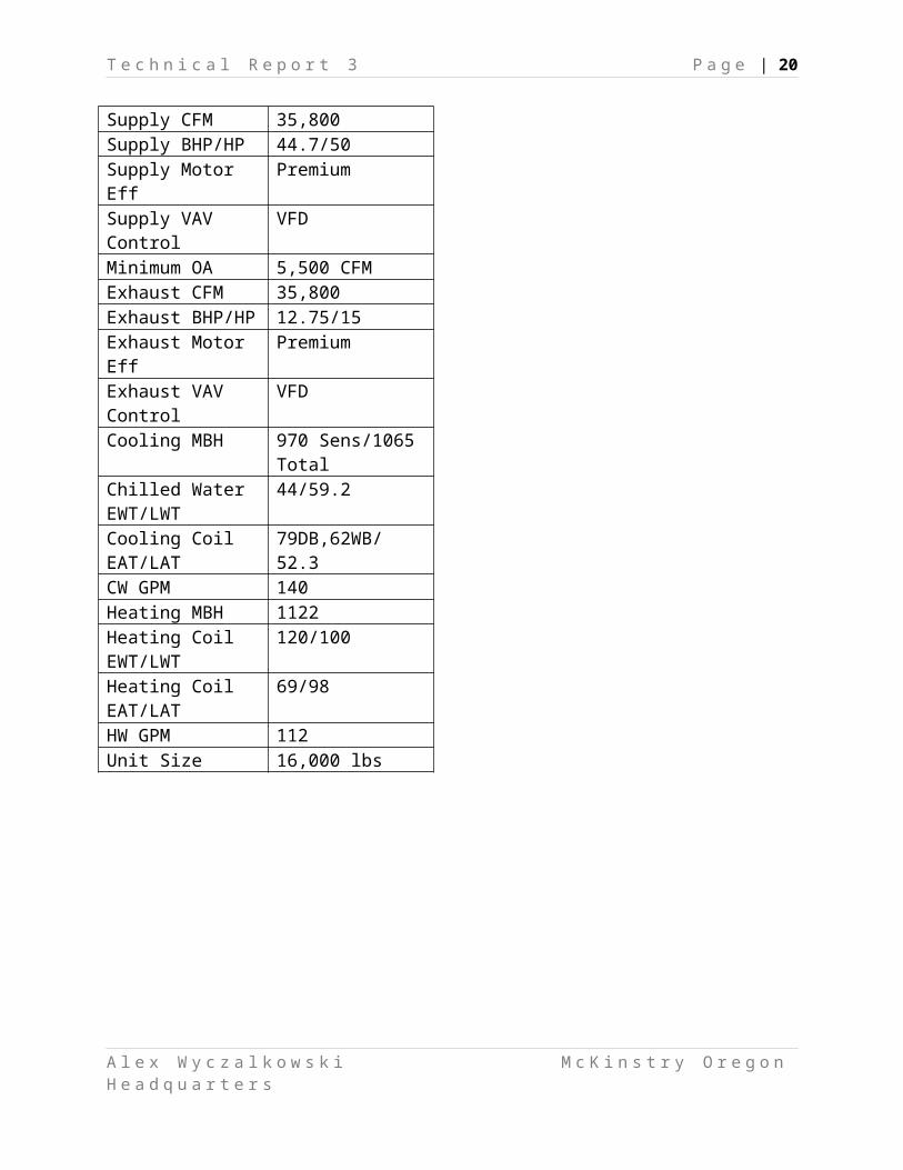
Table 10.4 Air Handler DetailsAIR HANDLING UNIT – AHU-1
Location RooftopSupply Fan Plug, Blow ThroughSupply CFM 35,800Supply BHP/HP 44.7/50Supply Motor Eff PremiumSupply VAV Control VFDMinimum OA 5,500 CFMExhaust CFM 35,800Exhaust BHP/HP 12.75/15Exhaust Motor Eff PremiumExhaust VAV Control
VFD
Cooling MBH 970 Sens/1065 TotalChilled Water EWT/LWT
44/59.2
Cooling Coil EAT/LAT
79DB,62WB/ 52.3
CW GPM 140Heating MBH 1122Heating Coil EWT/LWT
120/100
Heating Coil EAT/LAT
69/98
HW GPM 112Unit Size 16,000 lbs
A l e x W y c z a l k o w s k i M c K i n s t r y O r e g o n H e a d q u a r t e r s

T e c h n i c a l R e p o r t 3 P a g e | 13
Table 10.5. Hot Water Unit Heater DetailsHOT WATER UNIT HEATER – UH1
Location WarehouseHeating Coil EWT/LWT
120/100
Output MBH 100Fan Motor HP .09Weight 100 lbs
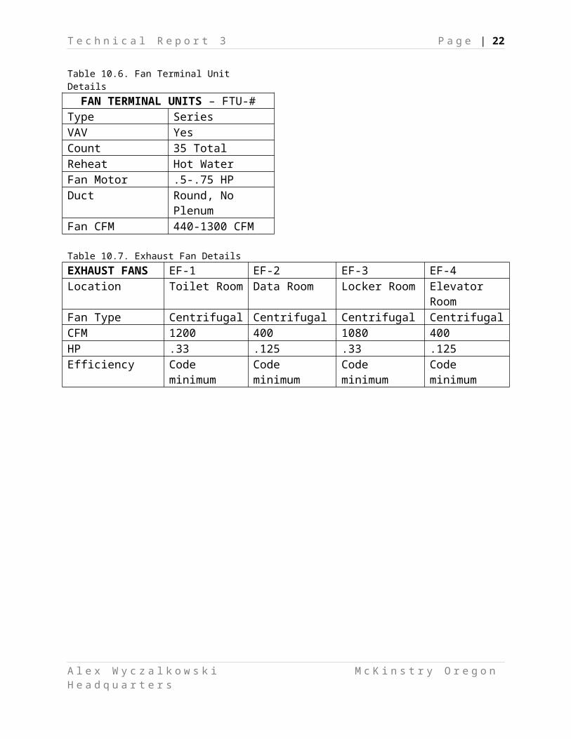
Table 10.6. Fan Terminal Unit Details
A l e x W y c z a l k o w s k i M c K i n s t r y O r e g o n H e a d q u a r t e r s

T e c h n i c a l R e p o r t 3 P a g e | 14
FAN TERMINAL UNITS – FTU-#Type SeriesVAV YesCount 35 TotalReheat Hot WaterFan Motor .5-.75 HPDuct Round, No PlenumFan CFM 440-1300 CFM
Table 10.7. Exhaust Fan DetailsEXHAUST FANS EF-1 EF-2 EF-3 EF-4Location Toilet Room Data Room Locker Room Elevator RoomFan Type Centrifugal Centrifugal Centrifugal CentrifugalCFM 1200 400 1080 400HP .33 .125 .33 .125Efficiency Code minimum Code minimum Code minimum Code minimum
A l e x W y c z a l k o w s k i M c K i n s t r y O r e g o n H e a d q u a r t e r s

T e c h n i c a l R e p o r t 3 P a g e | 15
11 System Operation Description
11.1 Air Handling Unit
Mode Control: Occupied/Unoccupied operation is according to a user determined schedule.
During unoccupied mode, a push button on a selected room sensor can operate the unit in
occupied mode for a set period (initially 2 hours). The system includes an equipment stagger
start function to minimize electrical demand. Normal operation can also be overridden by the
fire alarm system.
Supply Fan Control: In the medium pressure system, “the goal is to maintain duct static pressure
as low as possible. This is achieved by maintaining the critical zone air valve between 85%-95%
open.” (McKinstry RFP) The Building Management System (BMS) senses the damper position
of all Fan Terminal Units in the building. The unit that is most open is critical. If it’s less than
85%, the BMS tells the VFD to slow down the supply fan, increasing CFM. If it is more than
95%, the VFD speeds up the supply fan. The design duct static pressure set-point is 1.0”.
Supply Air Temperature Control: 3 options
1. OSA < 50ºF or Return Air < 68ºF: “Heating coil valve shall modulate to temper supply
air temperature as necessary”
2. Economizer Mode (OAT < SAT-Fan Heat): The BMS modulates OSA and RA dampers
to maintain SAT setpoint. If supply air reaches 100% OSA (airflow monitoring station),
the BMS opens the chilled water valve.
3. All other times: SAT is reset up or down 1º every 10 minutes based on “served zone
cooling loop output average value and hot zone count.”
Minimum Outside Air CFM Calculation: Sequence is based on ASHRAE standard 62-2001
Section 6.1.3.1 Multiple Spaces
A l e x W y c z a l k o w s k i M c K i n s t r y O r e g o n H e a d q u a r t e r s

T e c h n i c a l R e p o r t 3 P a g e | 16
11.2 Fan Terminal Units
Mode Control: See Mode Control for Air Handling Unit, Section 11.1
Occupied Mode: First stage of heating has the primary damper open to minimum. Second stage
of heating opens and modulates hot water valve. If zone temperature is too high, the heating
water valve will close and the primary air damper will modulate open to maintain set-point.
Supply fan is always on.
11.3 Heat Recovery Chiller and Well System
Mode Control: BMS enables operation of chiller to coincide with AHU and FTUs. Heating and
cooling modes are determined by number of zones that require heating or cooling. Normal
operation can be overridden by fire alarm system.
Cooling Mode: Chiller will operate in cooling mode when 60% of the zones are “hot zones” (i.e.
require cooling), AND the OSA > 55ºF. Condenser and evaporator water circulation pumps first
energize on call for cooling. The chiller will then operate once proof of flow is met. The chiller
will maintain 44ºF CHW supply temperature. Three way valves V-1, V-2, and V-3 will be
diverted as shown in Figure 9.2. Well water pumps energize and maintain full flow through heat
exchanger.
Heating Mode: The Chiller operates in heating mode when 60% of the zones are “cold zones”.
Like in cooling mode, the chiller will not turn on until proof of flow is met in the CDW and
CHW loops as to protect the chiller. The chiller will maintain 120 º F heating water supply
temperature. Three way valves V-1, V-2, and V-3 switch positions as shown in Figure 9.1. Well
water pumps turn on similar to cooling mode.
A l e x W y c z a l k o w s k i M c K i n s t r y O r e g o n H e a d q u a r t e r s

T e c h n i c a l R e p o r t 3 P a g e | 17
12 Mechanical System First Cost and Lost Space
Estimates for mechanical system first cost come to $1,394,511. This estimate consists of two
numbers, a Market Base ($644,842) and a Premium Price ($749,669). Market Base is an
estimate of the cost of a lowest-first cost system. The Premium Price includes upgrades to the
building like well drilling, Heat Pump System, hot water to fan terminal units, and Integrated
Technology Service (ITS). Full cost breakdown can be found in Appendix B of this report.
Lost space totals 986 SF. The mechanical room is 656 SF. In addition, a mechanical shaft
occupies an additional 30 SF on the second floor. A single air handling unit is located on the
roof and occupies 300 SF of roof area.
A l e x W y c z a l k o w s k i M c K i n s t r y O r e g o n H e a d q u a r t e r s

T e c h n i c a l R e p o r t 3 P a g e | 18
13 Mechanical LEED Analysis
13.1 Energy and Atmosphere Credit 1
ASHRAE Model Assumptions
The following table shows the differences between the as-proposed model from Technical Report 2
(Wyczalkowski) and the ASHRAE Baseline model created for this report.
Table 13.1.1. Proposed vs ASHRAE ModelSystem Proposed Model ASHRAE Baseline*Lighting .81 W/SF 1.1 W/SFHVAC System Customized Heat Recovery
Chiller with Open Loop GSHPPackaged Rooftop Heat Pump
Economizer Default High Limit = 75ºFWarehouse Heat Hot Water Unit Heater Electric ResistanceDHW Heater 95 % efficient 80% efficientExterior Walls R-13 (non-continuous) R9.5 (continuous)* All assumptions for Baseline model are from ASHRAE Standard 90.1 Appendix G
eQUEST Simulation Results
Figure 13.1.1. Electric consumption, gas consumption, and electricity breakdown
A l e x W y c z a l k o w s k i M c K i n s t r y O r e g o n H e a d q u a r t e r s

T e c h n i c a l R e p o r t 3 P a g e | 19
Table 13.1.2. Electric and gas consumption
Comparing the total numbers from the two models, there is not a large difference in overall
energy usage. Electric consumption reduced from 360,500 kWh to 331,500kWh. This is an
improvement of only 8%. However, after looking at the numbers more closely, there are some
interesting discrepancies. In the original model, Ventilation Fans accounted for 51,860kWh
(more than Heating), where as it only totals 28,780kWh in the Baseline Model. Ventilation
should not be more in the proposed model; in fact it should be lower because the proposed has
VAV and the baseline uses CAV. If the ventilation usage is lowered, we get a total improvement
of 14.4%. This amounts to 2 LEED points. In addition, pump energy is over 40 times higher in
the proposed model. The gas consumption is identical in both models, even though the proposed
model has a more efficient heater (95% versus 80%). In reality, the percent improvement is
probably greater than shown in this report.
A l e x W y c z a l k o w s k i M c K i n s t r y O r e g o n H e a d q u a r t e r s
T e c h n i c a l R e p o r t 3 P a g e | 20
13.2 Other LEED Creditd
Water Efficiency Credit 2: Innovative Wastewater Technologies
The McKinstry Oregon Headquarters utilizes Rainwater Harvesting to supplement water usage
in toilets throughout the building. Originally designers wanted to build enough storage to be
stand-alone. The winters in Portland are very wet, and summers are very dry, so a large amount
of water would need to be stored to last throughout the summer. However, due to payback
issues, the designers decided to have the system only be supplemental.
Energy and Atmosphere Credit 3: Enhanced Commissioning
McKinstry which self performs the mechanical design and construction for the Oregon HQ was
able to provide commissioning as well. However, they hired a 3rd party to commission the
building to work with them and ensure that the commissioning was done properly.
Energy and Atmosphere Credit 5: Measurement & Verification
As standard practice on all of their projects, McKinstry provides Measurement and Verification
on all of their projects. This ensures that all the installation and commissioning was done
correctly. Should there be any problems with the systems, measurement and verification assures
they will be addressed.
McKinstry Designers have provided a LEED checklist for their building. They are attempting to
achieve LEED Gold Rating. See Appendix C for the full checklist.
A l e x W y c z a l k o w s k i M c K i n s t r y O r e g o n H e a d q u a r t e r s

T e c h n i c a l R e p o r t 3 P a g e | 21
14 Overall Evaluation of SystemOverall, McKinstry Oregon Headquarters is a fairly efficient building. Although there are large
internal loads in the building with lighting and equipment, the building is fairly well insulated
and has an efficient mechanical system.
Space requirements in the building are fairly small. There is a small mechanical room in the
warehouse and an AHU on the roof. There are only two significant pieces of equipment in the
building, a chiller and the AHU. The heat recovery mode of the chiller eliminates the need for a
boiler.
The building has a fairly expensive mechanical system. It comes at a premium of $749,669 over
an industry standard system. Using an engineering economics equation, assuming a 6% interest
rate per year, energy cost savings would have to be $54,425 per year to break even in 30 years.
The system currently saves 52,050 kWh per year. Even at a generous $0.10/kWh, yearly savings
are $5,205/year. As stated earlier, the results from the energy model seemed inaccurate, but
energy savings would have to be significantly higher than modeled to give any sort of reasonable
payback. Note that increased LEED points will also give a significant rebate.
A significant portion of the premium cost is the open loop GSHP system. Drilling and Permits
alone cost $180,000. The Heat Pump System costs an additional $400,000. Hot water reheat in
the VAV units saves money, but comes at a cost of $125,000. Full breakdown of costs can be
found in Appendix B.
The wells may also have some issues with maintainability. If a pipe bursts underground, it can
become a large maintenance issue, as the wells go over 100 ft into the ground. Since the system
is open loop, there is also a risk that the pumps may bring in particles that may clog the system.
This would also be a large maintenance issue.
The VAV airside system is fairly commonplace today. There are several newer systems that can
be implemented instead such as under floor distribution systems, radiant panels, and even DOAS
systems.
A l e x W y c z a l k o w s k i M c K i n s t r y O r e g o n H e a d q u a r t e r s
T e c h n i c a l R e p o r t 3 P a g e | 22
15 ReferencesASHRAE. 2005, ANSI/ASHRAE, Portland Design Conditions. American Society of Heating Refrigeration and Air Conditioning Engineers, Inc., Atlanta, GA. 2007
ASHRAE. 2007, ANSI/ASHRAE, Standard 90.1 – 2007, Energy Standard For Buildings. American Society of Heating Refrigeration and Air Conditioning Engineers, Inc., Atlanta, GA. 2007
McKinstry. 2008. Design Documents. McKinstry, Seattle, WA. 2008
McKinstry: Portland Headquarters Building One. 2008. Prepared by Myer, Patty. Request For Proposal: Controls. McKinstry, Seattle, WA. 2008
Wozniak, Aaron. 2008. Personal Communication. Portland, OR. 2008
Wyczalkowski, Alex. 2008. Technical Reports 1 & 2. The Pennsylvania State University. 2008
A l e x W y c z a l k o w s k i M c K i n s t r y O r e g o n H e a d q u a r t e r s

T e c h n i c a l R e p o r t 3 P a g e | 23
16 Appendix A – Portland Design Conditions
A l e x W y c z a l k o w s k i M c K i n s t r y O r e g o n H e a d q u a r t e r s

T e c h n i c a l R e p o r t 3 P a g e | 24
17 Appendix B – System Costs Breakdown
A l e x W y c z a l k o w s k i M c K i n s t r y O r e g o n H e a d q u a r t e r s

T e c h n i c a l R e p o r t 3 P a g e | 25
18 Appendix C – LEED Project Checklist
A l e x W y c z a l k o w s k i M c K i n s t r y O r e g o n H e a d q u a r t e r s

T e c h n i c a l R e p o r t 3 P a g e | 26
A l e x W y c z a l k o w s k i M c K i n s t r y O r e g o n H e a d q u a r t e r s