Embed Size (px)
Citation preview

Fringing Effects in Re-entrant and Inverted Re-entrant Turnstile Waveguide Junctions Using Cylindrical Resonators
Joseph Helszajn, and John Sharp,
1. Abstract
One waveguide network is a 5-port turnstile junction consisting of three H-plane waveguides with a circular quarter wave long resonator on its axis, open circuited at one end and short circuited at the other. It is readily converted to a turnstile 3-port circulator by replacing the dielectric resonator by a gyromagnetic one and closing 2 of the 5 ports. Another network that may be reduced to a 3-port circulator is a 7 port turnstile junction containing a pair of similar coupled resonators or a half wave long arrangement open circuited at each end. The introduction of suitable symmetry planes in the latter two geometries suggests that all three have, in the absence of any fringing effects, the same centre frequency. In practice, however, this is not so. This paper employs an FE process to investigate this assumption in the cases of re-entrant and inverted re-entrant resonators. One conclusion of this work is that a FE or similar numerical tool is mandatory for the adjustment of such a degree-2 circuit.
2. Introduction
he original turnstile waveguide circulator has been described in [1]. Two practical implementations rely on either a single quarter wave long cylindrical resonator in a re-entrant or inverted re-entrant turnstile geometry [2,3,4]. The operation of this
class of circulator was originally clarified in [2]. A typical geometry may be visualised as a 5-port network consisting of an H-plane junction of three rectangular waveguides and an E-plane circular one supporting closed orthogonal ports. Two other families of such circulators rely on the two possible orientations of a prism resonator [5,6,7,8,9]. Figure 1 depicts the re-entrant and inverted re-entrant structures using single cylindrical resonators. Three port junction circulators based on a 7-port turnstile structure have also been described and some additional data on this class of circulators are available in [2,3,4]. The two possibilities are indicated in figures 2a and b . There are 6 geometries based on the 5-port turnstile junction and 6 based on the 7 port one, making 12 different possibilities altogether. The original turnstile junction circulator provides three more options.
T
The physical adjustment of this class of circulator reduces to two steps [10,11]. One step involves the degeneracy between the reflection coefficients of an in-phase and a pair of counter-rotating eigen-networks. The second step involves splitting the degeneracy between the latter two reflection coefficients by the application of the gyrotropy. One assumption met in this class of circulators is that the frequency variation of the in phase eigen-network may be ignored compared to that of the degenerate counter-rotating ones. A feature of any typical geometry under this condition is that each has, in the absence of fringing, the same centre frequency. It is then in principle, sufficient under this assumption, to restrict the investigation to the first circulation condition for one typical geometry and to reorganize it into the other configuration as necessary. The main conclusion of this work suggests that fringing effects in these structures are important and cannot be disregarded in practise.
Figure 1 Topologies of re-entrant and inverted re-entrant turnstile junctions using single quarter-wave resonators.
1
a
R
Re-entrantTurnstileJunction
InvertedRe-entrantTurnstileJunction
Ferrite
Mount
R
LS
R
LS

Figure 2 Mapping between single and pairs of quarter-wave or half-wave turnstile junctions.
The susceptance slope parameters of the geometry based on the 5-port turnstile arrangement, which is a measure of the bandwidth of the device is, in practice, twice that based on the 7-port junction [3]. The calculations summarized in this paper are undertaken at a frequency of 13.25 GHz in half-height WR75 waveguide. The choice of this structure is dictated by the fact that such junctions are usually coupled to regular waveguides by impedance transformers in the form of quarter-wave long half-height waveguides. The effect of the resonator mount and that of off-setting the gap of the junction are separately investigated. The introduction of a septum in the 7-port geometries is also investigated. Inverted re-entrant turnstile circulators using single quarter-wave long resonators open circuited at one flat face and short circuited at the other have been described in the literature using both small and large gap geometries [17]. The prototype used in the current investigation is based on the former arrangement.
3. Re-entrant and Inverted Re-entrant Turnstile Circulators
The turnstile re-entrant and inverted re-entrant configurations illustrated in figures 1 and 2 are sometimes asserted to have, in the absence of fringing, identical passband frequencies. This assumption is however not strictly true as will be demonstrated here. The prototype used for the purpose of calculations is the single re-entrant quarter-wave long geometry with one open flat face and one short-circuit flat face in half height waveguide. One typical solution in WR 75 waveguide for which a=19.05 mm and b= 4.76 mm at a frequency of 13.25 GHz is summarised by
2
Symmetry plane
gap
Ferrite
Mount
Symmetryplane

R and L are the dimensions of the resonator, is the length of the mount, k0 is the wave number, and qeff is the gap factor. The gap (S) of the junction is given in terms of the length of the resonator and the gap factor by
The ratio of the length of the mount ( ) to that of the opening of the waveguide (b) is also a parameter. The latter is however not an independent quantity in the description of the assembly. The above result applies to a dielectric resonator with a relative dielectric constant f equal to 15.10 with a relative permeability d=1.0, and a gap with a relative dielectric constant d equal to 1.0. The boundary conditions on the axis of the junction satisfy [10,11,12,13]
The boundary conditions at the terminals of the problem are
s0 is the in-phase reflection eigenvalue of the junction and s± are its degenerate counter-rotating reflection eigenvalues. These two conditions ensure that the in-phase and degenerate counter-rotating eigenvalues are commensurate and that the corresponding reflection angles are 180 deg. out of phase. It coincides with a return loss (R.L.) of 9½ dB at any port when the other two are terminated in matched loads.The frequency response of this solution is depicted in figure 3. Its physical geometry has been fixed by having recourse to a suitable solver based on a recently developed algorithm which ensures that the conditions in equations 2a and b are satisfied at the terminals of the junction. The reference plane employed in obtaining this result consisted of replacing the ferrite resonator by a metal post. This calibration assumes the electrical references of the in-phase and counter-rotating eigen-networks coincide; an assumption that may not be altogether valid in practice. The response of the dual geometry obtained by reorganizing the same parts into an inverted geometry is separately superimposed in figure 3. The frequency deviation of the reorganized assembly into an inverted turnstile one is, in this instance, of the order of 1 GHz at a centre frequency of 13.25 GHz.Figures 4a and b compare Smith chart representations of the in-phase and counter-rotating reflection eigenvalues and return loss of the two solutions between 12.75 GHz and 13.75 GHz. A scrutiny of this result indicates that the reorganized inverted re-entrant assembly not only displays a shift in frequency but also shifts in both the in-phase and degenerate counter-rotating eigenvalues. A separate scrutiny of the frequency responses of the in-phase and counter-rotating reflection eigenvalues of either solution indicates that the former reflection angle is essentially stationary and that the frequency dispersion of the overall junction is essentially fixed by the latter eigenvalues.
3
-12
-10
-8
-6
-4
-2
0
10.00 11.00 12.00 13.00 14.00 15.00 16.00Frequency (GHz)
Return Loss (dB)
-12
-10
-8
-6
-4
-2
0
10.00 11.00 12.00 13.00 14.00 15.00 16.00Frequency (GHz)
Return Loss (dB)

Figure 3 Frequency responses of optimum re-entrant and reorganized inverted re-entrant turnstile junctions in half height WR75 waveguide. (R/L=2.0)
Figure 4 Eigenvalue diagrams, in the admittance plane, of optimum re-entrant and reorganized inverted re-entrant turnstile junctions in half height WR75 waveguide. (R/L=2.0)
4. Non Optimum Filling Factor
The gap between the open-face of the resonator and one broad wall of the waveguide not only determines the first of the two circulation conditions of the circulator, but also partly fixes the susceptance slope parameter of the junction. The effect of an offset in this quantity is investigated here in the case of the
Figure 5 Eigenvalue solution, in the admittance plane, of re-entrant turnstile junctions with non-optimum filling factor in half-height WR75 waveguide (R/L=2.0, f0=13.25 GHz)
regular re-entrant turnstile junction in figure 1. The Smith chart produced by reducing the filling factor from its calculated value
4
s=0.379 mm
L=1.471mm
b=4.763mm
qeff=0.795
a=19.05 mm
R/L=2
13.25 GHz
Reference plane13.75 GHz
s�s0
S11
Reference plane13.25 GHz
s� s0
S11
12.75 GHz
13.75 GHz
12.75 GHz
s=0.630 mmL=1.471mm
b=5.014 mm
qeff=0.7
Reference plane
13.25 GHz
a=19.05 mm
R/L=2
s� s0
S11
s=0.630 mmL=1.471mm
b=5.01mmqeff=0.7
R0/R=1.2
13.25 GHz
Reference plane
a=19.05 mm
R
R0
R/L=2s�
s0S11
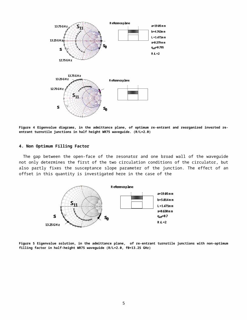
Figure 6 Eigenvalue solution, in the admittance plane, of re-entrant turnstile junction in half height WR75 waveguide using a resonator mount with an oversized radius (R/L=2.0, qeff=0.70)of approximately 0.8 to 0.7 by altering the length of the mount is indicated in figure 5. This modest offset of the filling factor results, at first sight, in not an insignificant perturbation of the in-phase and counter-rotating eigenvalues of the junction. A new reference plane at which the reflection coefficient of the junction is real at the midband frequency may be readily established approximately by introducing an electrically short U.E. with an appropriate impedance and length in the same waveguide. The
eigenvalue diagram of one possible solution is indicated in figure 6.
Figure 7 Relationship between qeff and R0/R, at 13.25 GHz in half height WR75 waveguide
In a degree-2 arrangement this U.E. is normally absorbed in the details of the transformer and need not produce anypractical difficulty. This suggests that the filling factor of the junction may not be as critical as once supposed. The relationship between qeff and the ratio of the radii of the ferrite and its platform is summarized in fig 7.
5. the standard WR75 waveguide
The turnstile junction is often characterized in a degree-1 arrangement but its implementation is more often than not embodied in a degree-2 circulator assembly. Figure 8 indicates a plan view of a degree-2 assembly. In practice the mount of the resonator is not fixed until the specification of the circulator or the impedance of the transformer is spelled out. A half height waveguide is in practice a good representation and has been adopted throughout this work. The purpose of this section is to investigate the effect of rehousing the re-entrant turnstile structure in figure 1 in standard WR75 waveguide for the sake of completeness. This may be done by comparing the frequency responses of the two assemblies. The offset between the two shown in figure 9 may in part be attributed to the different fringing effects of the two mounts.
5
R
R0
0.5
0.6
0.7
0.8
0.9
1 1.1 1.2 1.3 1.4 1.5
Gap
fact
or
R0/R

Figure 8 Topology of quarter-wave coupled re-entrant junction circulator.
Figure 9 Frequency offset between optimized half height and reorganized full height junctions
The reset solution is described in this instance by
The main differences between the two solutions is the sizes of gap factors of the two assemblies. A separate scrutiny of the bandwidths and the corresponding calculated values of the susceptance slope parameters of the two arrangements in figure 10 suggests that each quantity differs by about a factor of two. This feature may in part be understood by recognizing that the normalized admittances of the two waveguides differ also by the same factor and is in part due to the change in the gap factors of the two. In the design of a degree-2 circulator the susceptance slope parameter is actually normalized to the regular waveguide so that the characterization of this quantity in the latter waveguide is adequate for design as is usually assumed.
6
a
R
Partial HeightWaveguide
StandardWaveguide
Ferrite Resonator
a
R
Partial HeightWaveguide
StandardWaveguide
Ferrite Resonator
-12
-10
-8
-6
-4
-2
0
10.00 11.00 12.00 13.00 14.00 15.00 16.00
Frequency (GHz)
Return Loss (dB)
-12
-10
-8
-6
-4
-2
0
10.00 11.00 12.00 13.00 14.00 15.00 16.00
Return Loss (dB)
Frequency (GHz)

Figure 10 Comparison of optimum frequency responses of re-entrant turnstile junctions in full and half height waveguides
Fig 11 indicates the Smith Chart response of this arrangement about the design frequency of the junction. It is in good accord with its design specification.
Figure 11 Eigenvalue representation, in the admittance plane, of the optimized reciprocal junction.
6. The turnstile junction using a demagnetized magnetic insulator
Another perturbation of the junction under consideration is obtained by replacing the dielectric resonator by a demagnetized magnetic insulator. The demagnetized permeability is given in terms of the magnetization of the material and the frequency by [14]
7
s=1.339mmL=1.547mm
b=9.525mmqeff=0.536
Reference plane
a=19.05mm
R
R/L=2
s�s0
S11
13.25 GHz

Figure 12 Effect of demagnetized permeability on passband response of waveguide junction
is the gyromagnetic ratio , is the saturation magnetization (A/m), ω is the radian frequency (rad/sec). The effect of the permeability on the resonant frequency of this sort of junction has been investigated separately in ref [15]. Figure 12 illustrates the effect in half-height WR75 waveguide the case for which d=0.9.
It is also opportune to investigate the effect of the dielectric constant of the ferrite material.
Figure 13 Effect of tolerance in relative dielectric constant of frequency response of turnstile junctions in WR75 half height waveguide
The relative dielectric constant of garnet materials vary approximately in practice between 13.0 and 15.0 and that of ferrite materials between 10.0 and 13.0. The usual tolerance on these material quantities is +- 5%. Figure 13 shows the effect of altering the relative dielectric constant from 15.0 to 14.0.
7. Dielectric Spacer
Another perturbation of the junction is the introduction of a dielectric filler into the gap between the open flat face of the
8
-12
-10
-8
-6
-4
-2
0
10.00 11.00 12.00 13.00 14.00 15.00 16.00
Frequency (GHz)
Return Loss(dB)
r=15 14
-10
-9
-8
-7
-6
-5
-4
-3
-2
-1
0
10.0 11.0 12.0 13.0 14.0 15.0 16.0
d=1.0
d=0.9
Return Loss(dB)
Frequency(GHz)
-10
-9
-8
-7
-6
-5
-4
-3
-2
-1
0
10.0 11.0 12.0 13.0 14.0 15.0 16.0
d=1.0
d=0.9
Return Loss(dB)
Frequency(GHz)

resonator and the top surface of the mount or waveguide wall. This is sometimes done in order to avoid arcing in high peak power devices. It is also necessary in order to fix the half wave long assembly in figure 2. Figure 14 shows the effect of introducing such a filler with a relative dielectric constant of 1.6 on the frequency of the device. .
Figure 14 Effect of dielectric spacer on amplitude squared passband response of turnstile junction in WR75 half height waveguide
8. The Dielectric Sleeve
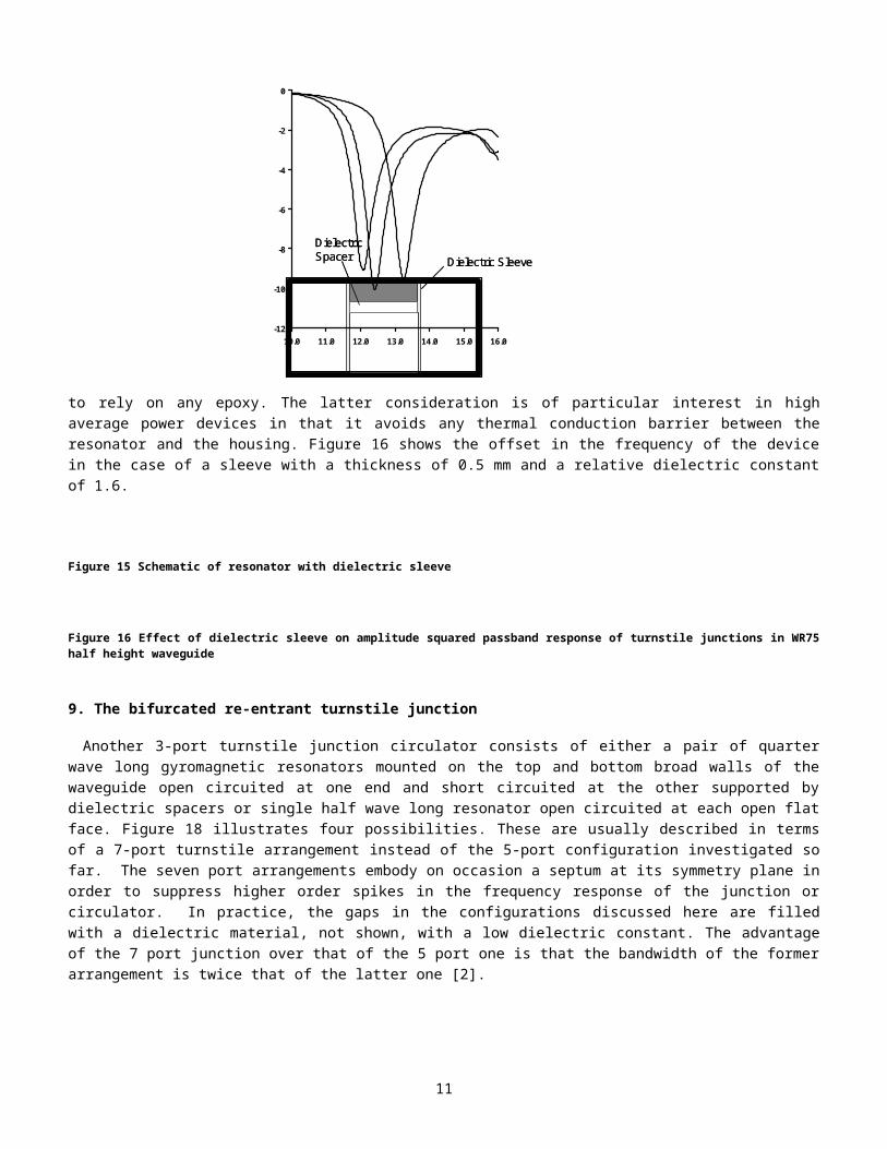
It is sometimes desirable to embody a dielectric sleeve into the resonator structure of the junction as depicted in figure 15 [16]. This is done in order to either fine tune its susceptance slope parameter or in order to hold the resonator without having to rely on any epoxy. The latter consideration is of particular interest in high average power devices in that it avoids any thermal conduction barrier between the resonator and the housing. Figure 16 shows the offset in the frequency of the device in the case of a sleeve with a thickness of 0.5 mm and a relative dielectric constant of 1.6.
Figure 15 Schematic of resonator with dielectric sleeve
9
Dielectric Spacer Dielectric Sleeve
Dielectric Spacer Dielectric Sleeve
-12
-10
-8
-6
-4
-2
0
10.0 11.0 12.0 13.0 14.0 15.0 16.0
d=1.0
d=1.6
Return Loss(dB)
Frequency(GHz)
spacer
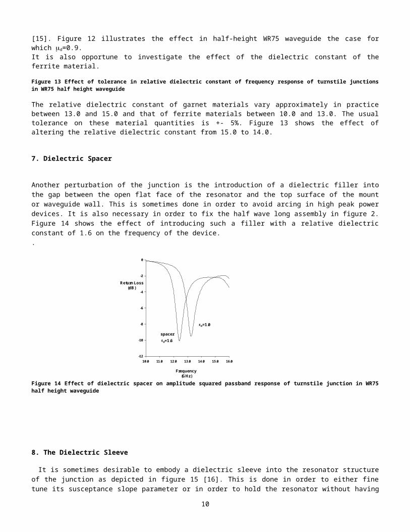
Figure 16 Effect of dielectric sleeve on amplitude squared passband response of turnstile junctions in WR75 half height waveguide
9. The bifurcated re-entrant turnstile junction
Another 3-port turnstile junction circulator consists of either a pair of quarter wave long gyromagnetic resonators mounted on the top and bottom broad walls of the waveguide open circuited at one end and short circuited at the other supported by dielectric spacers or single half wave long resonator open circuited at each open flat face. Figure 18 illustrates four possibilities. These are usually described in terms of a 7-port turnstile arrangement instead of the 5-port configuration investigated so far. The seven port arrangements embody on occasion a septum at its symmetry plane in order to suppress higher order spikes in the frequency response of the junction or circulator. In practice, the gaps in the configurations discussed here are filled with a dielectric material, not shown, with a low dielectric constant. The advantage of the 7 port junction over that of the 5 port one is that the bandwidth of the former arrangement is twice that of the latter one [2].
Figure 17 Bifurcated 7-port turnstile junctions
The frequency response of this class of junction is again to first order identical to that of the class of junction dealt with in this paper. The dielectric constant of the gap region is here taken as unity for simplicity sake. Figure 18 compares the frequency response of the geometry in figure 17(c) to that of the half height turnstile geometry in figure 3 by way of completeness. The thickness of the septum utilized in this calculation is 0.33 mm. A scrutiny of these two results indicates that the two have essentially the same bandwidth.
10
Septum
(a) (b)
(c) (d)
Septum
(a) (b)
(c) (d)
-12
-10
-8
-6
-4
-2
0
10.0 11.0 12.0 13.0 14.0 15.0 16.0
d=1.0
d=1.6
Return Loss (dB)
Frequency (GHz)
spacer
spacerandsleeve
The bandwidth of the 7-port in full height waveguide is the same as that of the 5 port turnstile junction in half height waveguide, but is twice that of the 5 port turnstile junction in full height waveguide. This may be understood by scrutinising the results in figure 10 in comparison with those under consideration in figure 18.
Figure 18 Frequency responses of 5-port turnstile junction in WR75 half height waveguide and 7 port turnstile junction in WR75 full height waveguide
10. Conclusion
The usual assumption in the design of turnstile, re-entrant turnstile and inverted re-entrant turnstile junction circulators using a single gyromagnetic resonator open circuited at one flat face and short circuited at the other, a similar pair of resonators or a half-wave long cylindrical one open circuited at each flat face is that each has the same passband frequency. It assumes that the fringing effects in the vicinity of a typical junction can be neglected. A study of the first of the two circulation conditions of this type of junction suggests that this is not so in practice. The effect of altering the housing of the junction on the frequency of a typical device and that of a non-optimum gap factor are also investigated. The paper separately includes some remarks about the susceptance slope parameter of this class of circulator.
11. References
[1] T. Schaug-Patterson, “Novel design of a 3-port circulator” Norwegian Defence Research Establishment Report, Rpt No. R-59, January 1958
[2] B. Owen and C. E. Barnes, “The compact turnstile circulator,” IEEE Trans. Microwave Theory Tech, vol. MTT-18, pp. 1096-1100, Dec. 1970.
[3] J. Helszajn and F. C. F. Tan, “ Susceptance slope parameter of waveguide partial-height ferrite circulators,” Proc. Inst. Elec. Eng., Vol. 122, no. 72, pp. 1329–1332, Dec. 1975.
[4] J. Helszajn and F. C. F, Tan, “Design data for radial waveguide circulators using partial-height ferrite resonators,” IEEE Trans. Microwave Theory and Tech, Vol. MTT-23, pp. 288–298, Mar 1975.
[5] Aitken, F. M. and Mclean, R., “Some properties of the waveguide Y circulator” Proc. Inst. Elec. Eng., vol. 110, no. 2, Feb. 1963.
[6] Y. Akaiwa, “Mode classification of a triangular ferrite post for Y-circulator,” IEEE Trans. Microwave Theory Tech., vol. MTT-25, pp. 59-61, Jan. 1977.
[7] J. Helszajn and J Sharp, “Resonant Frequencies, Q-factor, and susceptance slope parameter of waveguide circulators using weakly magnetized open resonators”, IEEE Trans. Microwave Theory Tech., vol. MTT-31, pp. 434-441, Jun. 1983.
[8] Y. Akaiwa, “Operation modes of a waveguide Y-circulator,” IEEE Trans. Microwave Theory and Tech., vol. MTT-22, pp. 954-959, Nov. 1974.
[9] J. Helszajn, “ Adjustment of degree-2 H-plane waveguide turnstile circulator using prism resonator,” Microwave Engineering Europe, pp 35-48, July, 1999
11
-12
-10
-8
-6
-4
-2
0
10.0 11.0 12.0 13.0 14.0 15.0 16.0
Frequency (GHz)
Return Loss(dB)
half height prototype
septum 18(c)

[10] Auld, B. A. , “The synthesis of symmetrical waveguide circulators,” IRE Trans. Microwave Theory Tech. vol. MTT-7, m. 238-246. Apr. 1959.
[11] Montgomery, C.G., Dicke, R.H. and Purcell, E.M., ‘Principles of Microwave’ Circuits (McGraw-Hill, New York, 1948).[12] J Helszajn and J Sharp, "Adjustment of in-phase mode in turnstile junction circulators", IEEE Trans Microwave Theory and
Tech., Vol. MTT-33, No 4, pp 339-343, April, 1985 [13] J Helszajn, and J Sharp, "Verification of First Circulation Condition of Turnstile Waveguide Circulators Using a Finite
Element Solver", IEEE Trans Microwave Theory and Tech., Vol. MTT-53, No 7, pp 2309-2316, July 2005[14] Schlomann, E., “Microwave behaviour of partially magnetized ferrites”, J.Appl. Phys., Vol. 41. pp. 204-214. Jan., 1970.[15] J. Helszajn and J Sharp, “Dielectric and permeability effects in HE111 open demagnetised ferrite resonators.” IEE
Proceedings, part H. Microwaves, Antennas and Propagation. Vol. 133, pp. 271-6. Aug. 1986[16] W S. Piotrowski and J. E. Raul, “Low-loss broad-band EHF circulator,” IEEE Trans. Microwave Theory and Tech., vol.
MTT-24, pp. 863–866, Nov. 1976.[17] Helszajn, J., “High-power waveguide circulators using quarter-wave long composite ferrite/dielectric resonators.” IEE
Proceedings H: Microwaves, Optics and Antennas. Vol. 128, pp. 268-73. Oct. 1981
12