Embed Size (px)
Citation preview

115 Physical Medium Dependent (PMD) and baseband medium, type 1000BASE-RH115.1 Overview
This clause specifies the 1000BASE-RH PMD and baseband medium for plastic optical fiber. In order to form a complete Physical Layer, it shall be integrated with the 1000BASE-H PCS and PMA of Clause 114, and integrated with the management functions which are accessible through the MDIO Interface defined in Clause 45.
115.2 Physical Medium Dependent (PMD) sublayer service interface
The following specifies the services provided by the 1000BASE-RH PMD. The PMD sublayer service interface is described in an abstract manner and does not imply any particular implementation.
The PMD Service Interface supports the exchange of analog electrical signals between PCS entities. The PMD translates the electrical analog signals to and from optical signals suitable for the specified medium.
The following primitives are defined:
PMD_COMSIGNAL.request
PMD_COMSIGNAL.indication
PMD_TXPWR.request
PMD_RXPWR.request
PMD_RXDETECT.indication
115.2.1 PMD_COMSIGNAL.request
This primitive defines the transfer of an analog signal amplitude from the PCS to the PMD.
115.2.1.1 Semantics of the primitive
PMD_COMSIGNAL.request(tx_signal).
During transmission, this primitive conveys to the PMD via the parameter tx_signal the amplitude of the output signal to be produced by the PMD transmit function.
115.2.1.2 When generated
The PCS transmit function continuously generates PMD_COMSIGNAL.request(tx_signal).
115.2.1.3 Effect of receipt
Upon receipt of this primitive the PMD converts tx_signal into the MDI optical signal. (See XX.)
115.2.2 PMD_COMSIGNAL.indication
This primitive defines the transfer of an analog signal amplitude from the PMD to the PCS.
115.2.2.1 Semantics of the primitive
PMD_COMSIGNAL.indication(rx_signal).
This primitive conveys to the PCS via the parameter rx_signal the relative amplitude of the optical signal received by the PMD at the MDI. (See XX.)
115.2.2.2 When generated
The PMD_COMSIGNAL.indication(rx_signal) is continuously generated by the PMD in the form of an analog signal.
1
115.2.2.3 Effect of receipt
The effect of receipt of this primitive is unspecified.
115.2.3 PMD_TXPWR.request
This primitive is used for optional EEE capability. The primitive is generated to request the minimum PMD optical output power compatible with Low Power Idle (LPI) mode, or normal operation When tx_pwr=OFF, the analog tx_signal is ignored.
115.2.3.1 Semantics of the primitive
PMD_TXPWR.request(tx_pwr).
The tx_pwr parameter can take one of the two values: ON or OFF
ON: The PMD Transmit function will generate signals at the MDI.
OFF: The PMD Transmit function will not generate signal at the MDI.
115.2.3.2 When generated
The PMD_TXPWR.request(tx_pwr) is generated during LPI mode to enable transmission of refresh signals and to reduce power consumption between such signals (see 114.5).
115.2.3.3 Effect of receipt
PMD_TXPWR.request(OFF) requests the PMD transmit function to produce the minimum optical output power compatible with LPI mode being the analog tx_signal ignored.
PMD_TXPWR.request(ON) requests the PMD transmit function to respond to PMD_COMSIGNAL.request primitives with generation of normal optical output..
115.2.4 PMD_RXPWR.request
This primitive is used for optional EEE capability. It is generated to request the PMD receive function to transition between being able to respond to received optical signals and a minimum power consumption state.
115.2.4.1 Semantics of the primitive
PMD_RXPWR.request(rx_pwr).
The rx_pwr parameter can take one of the two values: ON or OFF
ON: The PMD Receive function responds to receive MDI optical signals.
OFF: The PMD Receive function ignores receive MDI optical signals.
115.2.4.2 When generated
The PMD_RXPWR.request(rx_pwr) is generated during LPI mode to enable reception of refresh signals and to reduce power consumption between such signals (see Clause 114.5).
115.2.4.3 Effect of receipt
PMD_RXPWR.request(OFF) requests the PMD receive function to ignore the receive MDI signal and reduce power consumption. It also forces the PMD_RXDETECT.indication(signal_detect) to latch the signal_detect value when signal_detect = OK (see XX).
PMD_RXPWR.request(ON) requests the PMD receive function to respond to the received MDI signal.
115.2.5 PMD_RXDETECT.indication
This primitive is generated by the PMD receive function to indicate the status of the receive optical signal from the MDI.
2
115.2.5.1 Semantics of the service primitive
PMD_RXDETECT.indication(signal_detect)
The signal_detect parameter can take one of two values: OK or FAIL, indicating whether the PMD is detecting average optical power over a threshold (see XX) at the receiver (OK) or not (FAIL). When signal_detect = FAIL, then the rx_signal is undefined.
When rx_pwr = OFF, this primitive latches signal_detect value if signal_detect = OK, independently of optical signal level received at MDI. When rx_pwr = OFF is indicated while signal_detect = FAIL, it does not produce the signal_detect be latched.
NOTE—signal_detect = OK does not guarantee that rx_signal provides high enough quality to be able the PHY to establish the link. It just indicates that average optical power present at the MDI overpasses a threshold. It is possible for a poor quality link to provide sufficient average light power for a signal_detect = OK indication and still not meet the quality to establish the link with the BER objective.
115.2.5.2 When generated
The PMD receive function generates this primitive to indicate a change in the value of signal_detect.
115.2.5.3 Effect of receipt
The effect of receipt of this primitive by the client is unspecified by the PMD sublayer.
115.3 PMD functional specification
The 1000BASE-RH PMD performs the Transmit and Receive functions that convey analog signals between the PMD service interface and the MDI.
115.3.1 PMD block diagram
For purpose of system conformance, the PMD sublayer is defined at the following points, depicted in Figure 115-1. The optical transmit signal is defined at the output end of 1 meter of plastic optical fiber consistent with the link type connected to the MDI. All the specified transmitter measurements are made at TP2. The optical receive signals are specified and measured at the output of the fiber optic cabling (TP3) which in a link is connected to the receiver.
TP1 and TP4 are standardized reference points for use by implementers to certify component conformance. The electrical specifications of the PMD service interface (TP1 and TP4) are not system compliance points of this standard (these are not readily testable in a system implementation). It is expected that TP1 and TP4 may be specified in other components specification documents for certain applications (e.g., automotive).
Figure 115-1 – 1000BASE-RH PMD block diagram
3

115.3.2 Link topologies
Three link topologies and temperature environments are specified. Other topologies may be possible within the available optical power budget.
Table 115-1 – Specified link types
Type Ambient Temperature Environment Topology
Type A Consumer grade. 0 – 70ºC 50 m POF, 1 inline connection
Type B Industrial grade. -40 – 85ºC 50 m POF, 0 inline connection
Type C1 Automotive grade. -40 – 85ºC 15 m POF, 4 inline connections
Type C2 Automotive grade. -40 – 105ºC 15 m POF, 4 inline connections
Type C3 Automotive grade. -40 – 85ºC 40 m POF, no inline connections
Type C4 Automotive grade. -40 – 105ºC 40 m POF, no inline connections
115.3.3 PMD transmit function
The PMD transmit function translates abstract PMD service primitives into optical signals The transmit signal at the MDI is specified in XX.
The maximum amplitude of a PMD_COMSIGNAL.request(tx_signal) (see 115.2.1) shall correspond with the highest optical power at TP2. The minimum amplitude of a PMD_COMSIGNAL.request(tx_signal) shall correspond with the lowest optical power at TP2. Maximum and minimum optical signal levels shall meet the extinction ratio (ER) specifications and average optical launch power (LOP) specified for each topology.
Optionally, the PMD transmit function shall turn on and turn off the optical output as required by the PMD_TXPWR.request primitive. The transition times from receipt of this primitive are specified in XX.
115.3.4 PMD receive function
The PMD receive function translates the optical signal received at the MDI into the analog signal amplitude provided by the abstract PMD_COMSIGNAL.indication(rx_signal) primitive. The receive signal at the MDI is specified in XX.
Optionally, the PMD receive function shall respond or ignore the receive MDI signal, when LPI mode is used, through the PMD_RXPWR.request primitive. PMD_RXPWR.request(OFF) causes the PMD receive function to save the internal state of the circuitry to not be affected by the lack of received optical signal during quite periods of the LPI operation. In addition, the PMD receive function ignores the receive MDI signal and reduces its power consumption. The PMD receive function has to save the state to be able to quickly restart translation of received MDI signal during the refresh periods of time in LPI mode or when normal mode operation is resumed. PMD_RXPWR.request(ON) produces the PMD receive function to respond to the MDI optical signal for receiving the refresh signals in LPI mode or when normal operation of the PHY is resumed. The transition times from receipt of this primitive are specified in XX.
115.3.5 PMD signal detect function
The PMD Signal Detect function determines the value of the signal_detect parameter of PMD_RXDETECT.indication PMD service interface primitive., which is signaled when the value of signal_detect changes.
4

The value of the signal_detect parameter shall be generated according to the conditions defined in Table XX. The PMD receiver is not required to verify whether a compliant 1000BASE-H signal is being received. This standard imposes no response time requirements on the generation of the signal_detect parameter.
Table 115-2 – Signal detect value definition
Receive conditions Signal detect value
LOP at TP3 is < -35 dBm FAIL
LOP at TP3 > -29 dBm OK
All other conditions Unspecified
Implementation of the Signal Detect function shall generate the signal_detect parameter values in response to the average optical power present at the MDI.
Figure 115-2 shows the state diagram that defines the PMD signal detect function. State variables are defined in XX.
Figure 115-2 – Signal detect state diagram
Upon PMD device is powered on (power_on =TRUE), the PMD signal detect function transitions to PMDDET_FAIL state indicating signal_detect = FAIL. When receive optical power at MDI is higher than -29 dBm threshold, the state machine transitions to indicate signal_detect = OK (PMDDET_OK state). Once in this state, receive optical power at MDI has to decrease below -35 dBm to come back to PMDDET_FAIL state. By these separated threshold governing the transitions between PMDDET_FAIL and PMDDET_OK states, the state machine implements hysteresis on the signal_detect indication.
When PMD signal detect state machine is in PMDDET_OK state and rx_pwr = OFF is indicated, the signal_detect value is latched by the transition to PMDDET_LATCH state. Note that when this state is reached th PHY has established a reliable link and it is using rx_pwr to inhibit the PMD receive function during the LPI quiet periods of time. Once rx_pwr = ON the
5

state machine transition to PMDDET_OK, where the optical power is evaluated against thresholds again to decide signal_detect value by hysteresis.
115.3.5.1 PMD signal detect state variables
power_on
Indicates the power state of PMD. The state diagram takes the open-ended power_on = OFF branch.Values:
- ON: power to PMD device is provided and circuit is operative.- OFF: the PMD is power off.
lop_tp3
Indicates the average optical power received at MDI, measured at the specification point TP3 per optical measurements defined in XX.
115.3.5.2 PMD timers
maxwait_timer
A timer used to limit the amount of time during which a PMD receiver dwells in the PMDDET_LATCH state. The timer shall expire 50 μs ± 1 μs after being started. The timer is used in PMD signal detect state diagram.
115.4 PMD to MDI optical specification for 1000BASE-RH
115.4.1 Transmitter optical specifications
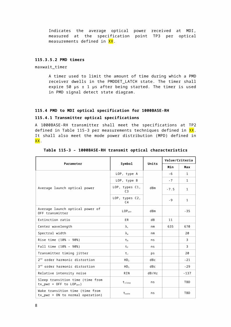
A 1000BASE-RH transmitter shall meet the specifications at TP2 defined in Table 115-3 per measurements techniques defined in XX. It shall also meet the mode power distribution (MPD) defined in XX.
Table 115-3 – 1000BASE-RH transmit optical characteristics
Parameter Symbol UnitsValue/Criteria
Min Max
Average launch optical power
LOP, type A
dBm
-6 1
LOP, type B -7 1
LOP, types C1, C3 -7.5 1
LOP, types C2, C4 -9 1
Average launch optical power of OFF transmitter LOPOFF dBm -35
Extinction ratio ER dB 11
Center wavelength λc nm 635 670
Spectral width λw nm 20
Rise time (10% – 90%) tR ns 3
Fall time (10% – 90%) tF ns 3
Transmitter timing jitter tJ ps 20
2nd order harmonic distortion HD2 dBc -21
3rd order harmonic distortion HD3 dBc -29
Relative intensity noise RIN dB/Hz -137
Sleep transition time (time from tx_pwr = OFF to LOPOFF) tsleep ns TBD
6

Wake transition time (time from tx_pwr = ON to normal operation) twake ns TBD
115.4.2 Receiver optical specifications
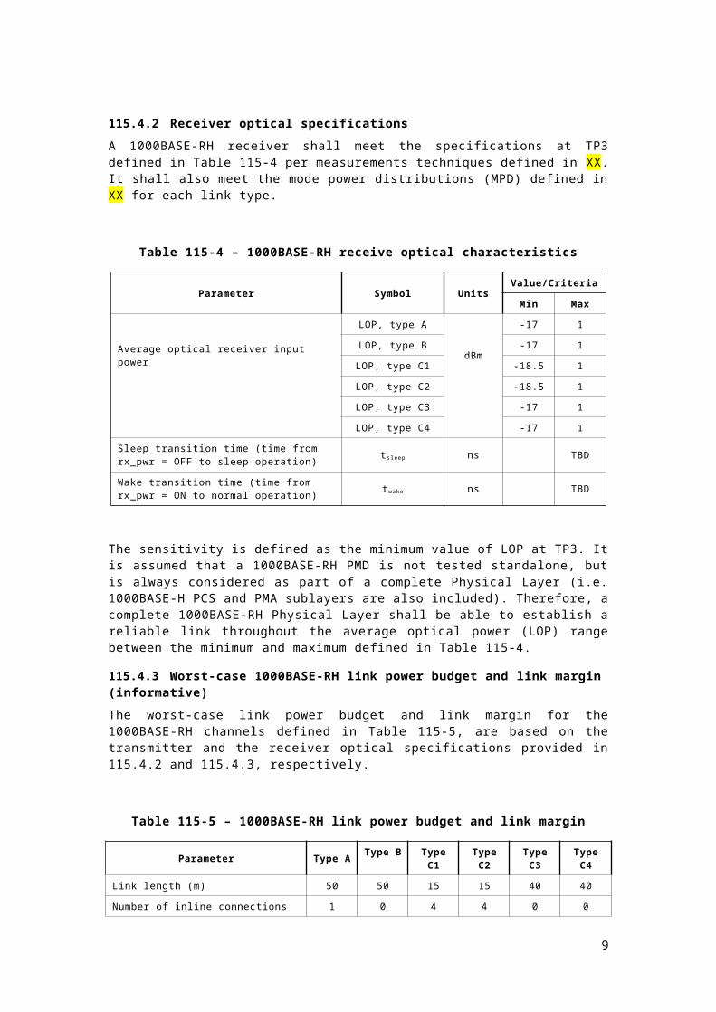
A 1000BASE-RH receiver shall meet the specifications at TP3 defined in Table 115-4 per measurements techniques defined in XX. It shall also meet the mode power distributions (MPD) defined in XX for each link type.
Table 115-4 – 1000BASE-RH receive optical characteristics
Parameter Symbol UnitsValue/Criteria
Min Max
Average optical receiver input power
LOP, type A
dBm
-17 1
LOP, type B -17 1
LOP, type C1 -18.5 1
LOP, type C2 -18.5 1
LOP, type C3 -17 1
LOP, type C4 -17 1
Sleep transition time (time from rx_pwr = OFF to sleep operation) tsleep ns TBD
Wake transition time (time from rx_pwr = ON to normal operation) twake ns TBD
The sensitivity is defined as the minimum value of LOP at TP3. It is assumed that a 1000BASE-RH PMD is not tested standalone, but is always considered as part of a complete Physical Layer (i.e. 1000BASE-H PCS and PMA sublayers are also included). Therefore, a complete 1000BASE-RH Physical Layer shall be able to establish a reliable link throughout the average optical power (LOP) range between the minimum and maximum defined in Table 115-4.
115.4.3 Worst-case 1000BASE-RH link power budget and link margin (informative)
The worst-case link power budget and link margin for the 1000BASE-RH channels defined in Table 115-5, are based on the transmitter and the receiver optical specifications provided in 115.4.2 and 115.4.3, respectively.
Table 115-5 – 1000BASE-RH link power budget and link margin
Parameter Type A Type B Type C1
Type C2
Type C3
Type C4
Link length (m) 50 50 15 15 40 40
Number of inline connections 1 0 4 4 0 0
Min LOP at TP2 (dBm) -6 -7 -7.5 -9 -7.5 -9
Plastic optical fiber max attenuation (dB) 9.5 10 3 3 8 8
Max insertion loss due to inline connections (dB) 1.5 0 6 6 0 0
Sensitivity at TP3 (dBm) -17 -17 -18.5 -18.5 -17 -17
Link margin (dB) 0 0 2 0.5 1.5 0
Link power budget (dB) 11 10 11 9.5 9.5 8
7
115.5 Optical measurement requirements
All the optical measurements of the transmitter shall be made at TP2 (at the end of a 1m length of POF cable consistent with the link type connected to the MDI). The optical measurements in the receiver shall be done at TP3.
The transmitter testing methodology assumes that a 1000BASE-RH PMD is not tested standalone, but is always considered as part of a complete Physical Layer (i.e. 1000BASE-H PCS and PMA sublayers are included). TP1 is not used as a stimulus point, rather the complete PHY is instructed through management to generate signals that are measured at TP2.
115.5.1 Center wavelength measurement
The center wavelength shall be measured using an optical spectrum analyzer per EIA/TIA standard FOTP-127/61.1, 1991. This shall be measured under normal conditions using a valid 1000BASE-H transmit signal as specified in 114.7.1. For this measurement, the PHY is not connected to any link partner, therefore the bidirectional link cannot be established and signal is not TH precoded and LPI mode is disabled.
The central wavelength is defined as:
where the power spectral density is measured in N points, taking the PSD P i (in watts/nm) for each λ i (in nm).
115.5.2 Spectral width measurement
The spectral width (RMS) shall be measured using an optical spectrum analyzer per EIA/TIA standard FOTP-127/61.3, 1991. The test conditions shall be the same as for center wavelength measurement (see 115.5.1).
The spectral width is defined as:
where the power spectral density is measured in N points, taking the PSD P i (in watts/nm) for each λ i (in nm).
115.5.3 Extinction Ratio (ER) measurement
The Extinction Ratio (ER) shall be measured in the time domain and measure maximum optical power (P1) and minimum optical power (P0) (defined in dBm):
P1 and P0 are measured in mW, as the integration of all the optical PSD along the complete spectrum. To make the effects on transmit signals from band limitation and possible AC coupling effects of the PMD transmitter negligible, a specific signal pattern shall be generated
8
0110 /log10 PPER
by the PCS. The signal pattern shall be generated configuring the PHY in Test mode 3 (see 114.8).
115.5.4 Average Optical Power (LOP) measurement
The LOP shall be measured at TP2 and TP3 by means of a large area photo-detector able to couple all the output optical power from the optical fiber.
In order to make the LOP measurement, considering the non-linear effects of the electrical-to-optical conversion of PMD transmitter, the test conditions shall be the same as center wavelength measurement (see 115.5.1).
115.5.5 Transmit rise/fall time characteristics
The transmit rise and fall time measurements shall be done using an electrical oscilloscope after optical to electrical conversion or an optical oscilloscope. The minimum required bandwidth of the optical-to-electrical converter and oscilloscope shall be 5/2 times the symbol rate FS. Therefore, the bandwidth provided by the apparatus, defined as -3dB cut-off frequency, shall be at least 812.5 MHz..
Rise time shall be measured as the time to transition the optical signal from 10% to 90% of maximum amplitude. In a similar way, the fall time shall be measured as the time to transition the optical signal from 90% to 10% of maximum amplitude.
The PHY shall be configured in Test mode 3 to make these measurements.
115.5.6 Transmitter timing jitter measurement
The transmitter timing jitter measurement shall be done using an internal or external optical to electrical converter and a general-purpose oscilloscope or jitter meter.
The PHY shall be configured in Test mode 2 to generate the signal pattern for the transmitter timing jitter measurement.
The RMS jitter of the crossing events of the PMD transmit signal with the average optical power, measured at TP2, relative to the corresponding edges of an unjittered clock reference with a frequency of FS/2 = 162.5 MHz shall be measured.
In order to guarantee null frequency deviation between the transmitter and the unjittered clock reference, the test instrument and testing device may share a low frequency clock reference if it can be proven this does not affect measurement accuracy.
115.5.7 Harmonic distortion measurement
The harmonic distortion (HD2 and HD3) measurement shall be done using an electrical spectrum analyzer after optical to electrical conversion. The minimum required bandwidth of the optical-to-electrical converter and apparatus shall be 5/2 times the symbol rate F S, equivalent to 812.5 MHz.
For this measurement the PHY shall operate in Test mode 4, generating a sine wave of frequency Fc (see 114.x). The harmonic distortion shall be measured as the power ratio of the 2nd harmonic at 2·Fc to carrier (Fc) and being the power ratio of the 3 rd harmonic at 3·Fc to carrier, for HD2 and HD3, respectively, returning the results in dBc. The resolution bandwidth (RBW) of the spectrum analyzer shall be less than 1 MHz.
115.5.8 Relative intensity noise (RIN) measurement
This test may not be an appropriate system level test in all implementations, but all implementations shall meet the specified performance. The PHY shall be configured in Test mode 5. RIN shall be measured according to Clause 58.7.7 with the following exceptions:
1) the low pass filter bandwidth is Fs/2 = 162.5 MHz
2) step d) of the test procedure is replaced by measuring the value of the photocurrent of the optical to electrical converter Ioe
9

3) step e) of the test procedure is replaced by using the following equation to evaluate RIN:
RIN=10 log10
PNBW ×I oe
2 ×R−G (dB/Hz)
where:
RIN is the relative intensity noise,
PN is the electrical noise power in Watts with modulation off,
BW is the low-pass bandwidth ot apparatus – high-pass bandwidth of apparatus du to DC blocking capacitor,
Ioeis the photocurrent of the optical to electrical converter,
R is the effective load impedance of the optical to electrical converter (for example, a 50 ohm detector load in parallel with a 50 ohm power meter would give R equal to 25),
G is the Gain in dB of any amplifier in the noise measurement path.
115.5.9 Mode power distribution specifications
The mode power distribution (MPD) specifications at TP2 and TP3 are defined by encircled angular flux (EAF) measurement method based on two-dimensional far field pattern data captured at TP2 and TP3, respectively. EAF measurement method shall conform to IEC 61300-3-54 defined for step-index multi-mode fibers as that defined in 115.8.
The MPD measured per EAF at TP2 or TP3 shall be contained between the upper and lower bound limits defined in Figures 115-2 to 115-5 for each link type.
Figure 115-2 –EAF template specification at TP2. Any link type
<insert figure>
Figure 115-3 –EAF template specification at TP3. Type A, B
<insert figure>
Figure 115-4 –EAF template specification at TP3. Type C1, C2
10

<insert figure>
Figure 115-5 –EAF template specification at TP3. Type C3, C4
115.6 Environmental specifications for automotive applications
115.6.1 General safety
All equipment subject to this clause shall conform to IEC 60950-1 (for IT and motor vehicle applications) and to ISO 26262 (for motor vehicle applications only, if required by the given application). All equipment subject to this clause may be additionally required to conform to applicable local, state, or national motor vehicle standards or as agreed to between the customer and supplier.
115.6.2 Environmental Safety
The 1000BASE-RH PHY is designed to operate in the automotive environment. All equipment in automotive applications shall conform to the potential environmental stresses with respect to their mounting location, as defined in the following specifications:
a) general loads: ISO 16750-1,b) electrical loads: ISO 16750-2, ISO 7637-2:2008, and ISO 8820-1,c) mechanical loads: ISO 16750-3, ASTM D4728, and ISO 12103-1,d) climatic loads: ISO 16750-4 and IEC 60068-2-1/27/30/38/52/64/78,e) chemical loads: ISO 167540-5 and ISO 20653
Automotive environmental conditions are generally more severe than those found in many commercial environments.
The targeted application environment(s) require careful analysis prior to implementation.
115.6.3 Electromagnetic Compatibility
A system integrating the 1000BASE-RH PHY shall comply with all applicable local and national codes, or as agreed to between the customer and the supplier, for the limitation of electromagnetic interference. A 1000BASE-RH PHY shall be tested according to IEC CISPR 25 test methods defined to measure the PHY's EMC performance in terms of RF immunity and RF emissions. When used in an an automotive environment, a 1000BASE-RH PHY shall meet the following motor vehicle EMC requirements:
a) Radiated/Conducted Emissions: CISPR 25, IEC 61967-1/4, and IEC 61000-4-21b) Radiated/Conducted Immunity: ISO 11452, IEC 62132-1/4, and IEC 61000-4-21c) Electrostatic Discharge: ISO 10605 and IEC 61000-4-2/3d) Electrical Disturbances: IEC 62215-3 and ISO 7637-2/3
Exact test setup and test limit values may be adapted to each specific application, subject to agreement between the customer and the supplier.
115.7 Optical Safety
Even when a Light Emitting Diode (LED) is used to generate the optical signal in equipment implemented according to this clause, 1000BASE-RH transceivers shall be Hazard Level 1 laser certified under any condition of operation. This includes single fault conditions whether coupled into a fiber or out of an open bore. Transceivers shall be certified to be in conformance with IEC 60825-1 and IEC 60825-2.
Conformance to additional laser safety standards may be required for operation within specific geographic regions.
115.8 Characteristics of the fiber optic cabling
The PMD subject to this clause is for a plastic optical fiber cable with a multimode optical fiber IEC 60793-2-40 types A4a.2. The cable shall be duplex.
11

115.9 Medium Dependent Interface (MDI)
The 1000BASE-RH PMD is coupled to the fiber optic cabling through a connection at the Medium Dependent Interface (MDI). An MDI mechanical interface is not specified by this clause. The MDI does not assume the use or non-use of optical connectors. (Some POF devices clamp the POF cable next to a lens without a connector, others use a plug and receptical connection.) Different MDI specifications are specified for the link types listed in Table 115-1.
Because a MDI mechanical interface is not specified, the transmit signal characteristics are defined at the output end of a 1m length (TP2) of plastic optical fiber. In the same way, the optical receive signal is defined at the output of the fiber optic cabling (TP3). Therefore, both the transmitter and the receiver optical characteristics are independent of the MDI mechanical implementation.
12