Embed Size (px)
Citation preview

Unit 12 Waves
348 minutes
344 marks
Q1.The diagram below shows three transparent glass blocks A, B and C joined together. Each glass block has a different refractive index.
(a) State the two conditions necessary for a light ray to undergo total internal reflection at the boundary between two transparent media.

condition 1 .....................................................................................................
........................................................................................................................
condition 2 .....................................................................................................
........................................................................................................................(2)
(b) Calculate the speed of light in glass A.
refractive index of glass A = 1.80
speed of light ..................................... ms−1
(2)
(c) Show that angle θ is about 30o.
(2)
(d) The refractive index of glass C is 1.40.
Calculate the critical angle between glass A and glass C.
critical angle ................................. degrees(2)
(e) (i) State and explain what happens to the light ray when it reaches the boundary between glass A and glass C.
...............................................................................................................
...............................................................................................................
...............................................................................................................(2)
(ii) On the diagram above continue the path of the light ray after it strikes the boundary

between glass A and glass C.(1)
(Total 11 marks)
Q2.Earthquakes produce transverse and longitudinal seismic waves that travel through rock. The diagram below shows the displacement of the particles of rock at a given instant, for different positions along a transverse wave.
(a) State the phase difference between
(i) points A and B on the wave ...................................................................
(ii) points A and C on the wave ...................................................................(2)
(b) Describe the motion of the rock particle at point B during the passage of the next complete cycle.
........................................................................................................................
........................................................................................................................
........................................................................................................................
........................................................................................................................
........................................................................................................................(2)
(c) A scientist detects a seismic wave that is polarised. State and explain what the scientist can deduce from this information.
........................................................................................................................
........................................................................................................................
........................................................................................................................(2)

(d) The frequency of the seismic wave is measured to be 6.0 Hz.
(i) Define the frequency of a progressive wave.
...............................................................................................................
...............................................................................................................(1)
(ii) Calculate the wavelength of the wave if its speed is 4.5 × 10³ m s−1.
wavelength .......................................... m(2)
(Total 9 marks)
Q3.(a) A laser emits monochromatic light.
Explain the meaning of the term monochromatic light.
........................................................................................................................
........................................................................................................................(1)
(b) The diagram below shows a laser emitting blue light directed at a single slit, where the slit width is greater than the wavelength of the light. The intensity graph for the diffracted blue light is shown.

The laser is replaced by a laser emitting red light.
On the axes shown in the diagram above sketch the intensity graph for a laser emitting red light.
(2)
(c) State and explain one precaution that should be taken when using laser light
........................................................................................................................
........................................................................................................................
........................................................................................................................(2)
(d) The red laser light is replaced by a non-laser source emitting white light.
Describe how the appearance of the pattern would change.

........................................................................................................................
........................................................................................................................
........................................................................................................................
........................................................................................................................
........................................................................................................................
........................................................................................................................(3)
(Total 8 marks)
Q4.The diagram below shows a section of a typical glass step-index optical fibre used for communications.
(a) Show that the refractive index of the core is 1.47.
(1)
(b) The refracted ray meets the core-cladding boundary at an angle exactly equal to the critical angle.
(i) Complete the diagram above to show what happens to the ray after it strikes the boundary at X.
(2)
(ii) Calculate the critical angle.
critical angle = .........................degrees(1)

(iii) Calculate the refractive index of the cladding.
refractive index = .....................................(2)
(c) Give two reasons why optical fibres used for communications have a cladding.
reason 1......................................................................................................
....................................................................................................................
reason 2......................................................................................................
....................................................................................................................(2)
(Total 8 marks)
Q5.Discuss the formation of stationary waves on a string or rope. Your account should include:
• a labelled diagram of a stationary wave
• the conditions necessary for stationary waves to form
• a definition of the terms node and antinode
• an explanation of how nodes and antinodes form.
The quality of written communication will be assessed in your answer.(Total 6 marks)
Q6.The diagram below shows the paths of microwaves from two narrow slits, acting as coherent sources, through a vacuum to a detector.

(a) Explain what is meant by coherent sources.
........................................................................................................................
........................................................................................................................
........................................................................................................................
........................................................................................................................(2)
(b) (i) The frequency of the microwaves is 9.4 GHz.
Calculate the wavelength of the waves.
wavelength = ................................. m(2)
(ii) Using the diagram above and your answer to part (b)(i), calculate the path difference between the two waves arriving at the detector.

path difference = ................................. m(1)
(c) State and explain whether a maximum or minimum is detected at the position shown in the diagram above.
........................................................................................................................
........................................................................................................................
........................................................................................................................
........................................................................................................................(3)
(d) The experiment is now rearranged so that the perpendicular distance from the slits to the detector is 0.42 m. The interference fringe spacing changes to 0.11 m.
Calculate the slit separation. Give your answer to an appropriate number of significant figures.
slit separation = ................................. m(3)
(e) With the detector at the position of a maximum, the frequency of the microwaves is now doubled. State and explain what would now be detected by the detector in the same position.
........................................................................................................................
........................................................................................................................
........................................................................................................................
........................................................................................................................(3)
(Total 14 marks)
Q7. Figure 1 shows a cross-section through an optical fibre used for communications.
Figure 1

(a) (i) Name the part of the fibre labelled X.
...............................................................................................................(1)
(ii) Calculate the critical angle for the boundary between the core and X.
answer = .........................degrees(2)
(b) (i) The ray leaves the core at Y. At this point the fibre has been bent through an angle of 30° as shown in Figure 1.
Calculate the value of the angle i.
answer = .........................degrees(1)

(ii) Calculate the angle r.
answer = .........................degrees(2)
(c) The core of another fibre is made with a smaller diameter than the first, as shown inFigure 2. The curvature is the same and the path of a ray of light is shown.
Figure 2
(c) State and explain one advantage associated with a smaller diameter core.
........................................................................................................................
........................................................................................................................
........................................................................................................................
........................................................................................................................

........................................................................................................................(2)
(Total 8 marks)
Q8. When a note is played on a violin, the sound it produces consists of the fundamental and many overtones.
Figure 1 shows the shape of the string for a stationary wave that corresponds to one of these overtones. The positions of maximum and zero displacement for one overtone are shown. Points A and B are fixed. Points X, Y and Z are points on the string.
Figure 1
(a) (i) Describe the motion of point X.
...............................................................................................................
...............................................................................................................
...............................................................................................................
...............................................................................................................(2)
(ii) State the phase relationship between
X and Y .................................................................................................
X and Z .................................................................................................(2)
(b) The frequency of this overtone is 780 Hz.
(i) Show that the speed of a progressive wave on this string is about 125 ms–1.
(2)
(ii) Calculate the time taken for the string at point Z to move from maximum displacement back to zero displacement.

answer = ................................... s(3)
(c) The violinist presses on the string at C to shorten the part of the string that vibrates.Figure 2 shows the string between C and B vibrating in its fundamental mode. The length of the whole string is 320 mm and the distance between C and B is 240 mm.
Figure 2
(i) State the name given to the point on the wave midway between C and B.
...............................................................................................................(1)
(ii) Calculate the wavelength of this stationary wave.
answer = ................................... m(2)
(iii) Calculate the frequency of this fundamental mode. The speed of the progressive wave remains at 125 ms–1.
answer = .................................Hz(1)
(Total 13 marks)

Q9. The figure below shows two ways in which a wave can travel along a slinky spring.
(a) State and explain which wave is longitudinal.
........................................................................................................................
........................................................................................................................(2)
(b) On the figure above,
(i) clearly indicate and label the wavelength of wave B(1)
(ii) use arrows to show the direction in which the points P and Q are about to move as each wave moves to the right.
(2)
(c) Electromagnetic waves are similar in nature to wave A.
Explain why it is important to correctly align the aerial of a TV in order to receive the strongest signal.
........................................................................................................................
........................................................................................................................
........................................................................................................................
........................................................................................................................(2)
(Total 7 marks)
Q10. (a) In an experiment, a narrow beam of white light from a filament lamp is directed at

normal incidence at a diffraction grating. Complete the diagram in the figure below to show the light beams transmitted by the grating, showing the zero-order beam and the first-order beams.
(3)
(b) Light from a star is passed through the grating.
Explain how the appearance of the first-order beam can be used to deduce one piece of information about the gases that make up the outer layers of the star.
........................................................................................................................
........................................................................................................................
........................................................................................................................
........................................................................................................................(2)
(c) In an experiment, a laser is used with a diffraction grating of known number of lines per mm to measure the wavelength of the laser light.
(i) Draw a labelled diagram of a suitable arrangement to carry out this experiment.
(2)
(ii) Describe the necessary procedure in order to obtain an accurate and reliable value for the wavelength of the laser light.Your answer should include details of all the measurements and necessary calculations.The quality of your written communication will be assessed in your answer.
...............................................................................................................

...............................................................................................................
...............................................................................................................
...............................................................................................................
...............................................................................................................
...............................................................................................................
...............................................................................................................
...............................................................................................................
...............................................................................................................
...............................................................................................................
...............................................................................................................
...............................................................................................................
...............................................................................................................(6)
(Total 13 marks)
Q11. The figure below shows a glass prism. Light is directed into the prism at an angle of 56°.The path of the ray of light is shown as is it enters the prism.
(a) (i) Calculate the refractive index of the glass.

answer = ......................................(2)
(ii) Calculate the critical angle for the glass-air boundary.
answer = ......................... degrees(2)
(b) On the figure above, continue the path of the ray of light until it emerges from the prism.(2)
(Total 6 marks)
Q12. The figure below shows a continuous progressive wave on a rope. There is a knot in the rope.
(a) Define the amplitude of a wave.
........................................................................................................................
........................................................................................................................(2)
(b) The wave travels to the right.Describe how the vertical displacement of the knot varies over the next complete cycle.
........................................................................................................................
........................................................................................................................

........................................................................................................................
........................................................................................................................
........................................................................................................................(3)
(c) A continuous wave of the same amplitude and frequency moves along the rope from the right and passes through the first wave. The knot becomes motionless.Explain how this could happen.
........................................................................................................................
........................................................................................................................
........................................................................................................................
........................................................................................................................
........................................................................................................................
........................................................................................................................(3)
(Total 8 marks)
Q13. (a) The speed of light is given by
c = f λ
State how each of these quantities will change, if at all, when light travels from air to glass.
c .......................................................
f ........................................................
λ .......................................................(3)
Figure 1 shows a side view of a step index optical fibre.
Figure 1
(b) Ray A enters the end of the fibre and then undergoes total internal reflection.
On Figure 1 complete the path of this ray along the fibre.(2)
(c) (i) The speed of light in the core is 2.04 × 10⁸ ms–1. Show that the refractive index of the core is 1.47.
(2)
(ii) Show that the critical angle at the boundary between the core and the cladding is about 80°.
refractive index of the cladding = 1.45
(2)
(d) Ray B enters the end of the fibre and refracts along the core-cladding boundary. Calculate the angle of incidence, θ, of this ray at the point of entry to the fibre.
answer = ...................................... degrees

(3)
(e) Figure 2 shows a pulse of monochromatic light (labelled X) that is transmitted a significant distance along the fibre. The shape of the pulse after travelling along the fibre is labelled Y. Explain why the pulse at Y has a lower amplitude and is longer than it is at X.
Figure 2
......................................................................................................................
......................................................................................................................
......................................................................................................................
......................................................................................................................(2)
(Total 14 marks)
Q14. A scientist is going to use a double-slit arrangement to carry out measurements in order to determine the wavelength of light from a laser.
(a) The scientist has a double slit of known separation. Describe the measurements that need to be taken and explain how they are used to find the wavelength of the light. Discuss any necessary safety precautions and how you would arrange the apparatus to improve accuracy.
The quality of your written communication will be assessed in this question.
......................................................................................................................
......................................................................................................................
......................................................................................................................

......................................................................................................................
......................................................................................................................
......................................................................................................................
......................................................................................................................
......................................................................................................................
......................................................................................................................
......................................................................................................................
......................................................................................................................
......................................................................................................................
......................................................................................................................
......................................................................................................................
......................................................................................................................
......................................................................................................................(6)
(b) In 1802 Thomas Young used candle light to observe the interference pattern from twonarrow slits acting as coherent light sources.
Explain what is meant by coherent light sources.
......................................................................................................................
......................................................................................................................
......................................................................................................................(2)
(c) Sketch and label on the diagram below the arrangement that Young would have used toobtain his interference pattern.
(2)

(d) State two differences in the appearance of the pattern obtained with a laser and thatproduced by a white light source such as a candle.
Difference 1 ..................................................................................................
......................................................................................................................
Difference 2 ..................................................................................................
.......................................................................................................................(2)
(e) Explain how the wave theory of light accounts for the areas on the screen where theintensity is a minimum.
.......................................................................................................................
.......................................................................................................................
.......................................................................................................................
.......................................................................................................................(2)
(Total 14 marks)
Q15. A single slit diffraction pattern is produced on a screen using a laser. The intensity of the central maximum is plotted on the axes in the figure below.
(a) On the figure above, sketch how the intensity varies across the screen to the right of the central maximum.
(2)
(b) A laser is a source of monochromatic, coherent light. State what is meant by

monochromatic light ....................................................................................
......................................................................................................................
coherent light ...............................................................................................
......................................................................................................................(2)
(c) Describe how the pattern would change if light of a longer wavelength was used.
......................................................................................................................
......................................................................................................................(1)
(d) State two ways in which the appearance of the fringes would change if the slit was made narrower.
......................................................................................................................
......................................................................................................................(2)
(e) The laser is replaced with a lamp that produces a narrow beam of white light. Sketch and label the appearance of the fringes as you would see them on a screen.
(3)
(Total 10 marks)
Q16. The figure below shows a stationary wave on a string. The string is tied onto a thin metal bar at A and fixed at B. A vibration generator causes the bar to oscillate at a chosen frequency.

Explain how a stationary wave is formed. Then describe the key features of the stationary wave shown in the figure above.
The quality of your written answer will be assessed in this question.
...............................................................................................................................
...............................................................................................................................
...............................................................................................................................
...............................................................................................................................
...............................................................................................................................
...............................................................................................................................
...............................................................................................................................
...............................................................................................................................
...............................................................................................................................
...............................................................................................................................
...............................................................................................................................
...............................................................................................................................
...............................................................................................................................
...............................................................................................................................(Total 6 marks)
Q17. The figure below shows a layer of oil that is floating on water in a glass container. A ray of light in the oil is incident at an angle of 44° on the water surface and refracts.

The refractive indices of the materials are as follows.
refractive index of oil = 1.47refractive index of water = 1.33refractive index of the glass = 1.47
(a) Show that the angle of refraction θ in the figure above is about 50°.
(2)
(b) The oil and the glass have the same refractive index. On the figure above, draw the path of the light ray after it strikes the boundary between the water and the glass and enters the glass. Show the value of the angle of refraction in the glass.
(2)
(c) Explain why the total internal reflection will not occur when the ray travels from water to glass.
......................................................................................................................
......................................................................................................................
......................................................................................................................(1)
(d) Calculate the critical angle for the boundary between the glass and air.

answer = ......................... degrees(2)
(e) On the figure above, complete the path of the ray after it strikes the boundary between the glass and air.
(2)(Total 9 marks)
Q18. (a) Define the amplitude of a wave.
......................................................................................................................
......................................................................................................................(1)
(b) (i) Other than electromagnetic radiation, give one example of a wave that is transverse.
.............................................................................................................(1)
(ii) State one difference between a transverse wave and a longitudinal wave.
.............................................................................................................
.............................................................................................................(1)
(c) The figure below shows two identical polarising filters, A and B, and an unpolarised light source. The arrows indicate the plane in which the electric field of the wave oscillates.
(i) If polarised light is reaching the observer, draw the direction of the transmission axis on filter B in the figure below.

(1)
(ii) The polarising filter B is rotated clockwise through 360º about line XY from the position shown in the figure above. On the axes below, sketch how the light intensity reaching the observer varies as this is done.
(2)
(d) State one application, other than in education, of a polarising filter and give a reason for its use.
......................................................................................................................
......................................................................................................................
......................................................................................................................
......................................................................................................................(2)
(Total 8 marks)

Q19. For a plane transmission diffraction grating, the diffraction grating equation for the first order beam is:
λ = d sin θ
(a) The figure below shows two of the slits in the grating. Label the figure below with the distances d and λ.
(2)
(b) State and explain what happens to the value of angle θ for the first order beam if the wavelength of the monochromatic light decreases.
......................................................................................................................
......................................................................................................................
......................................................................................................................
......................................................................................................................(2)
(c) A diffraction grating was used with a spectrometer to obtain the line spectrum of star Xshown in the figure below. Shown are some line spectra for six elements that have been obtained in the laboratory.
Place ticks in the boxes next to the three elements that are present in the atmosphere of star X.

(2)
(d) The diffraction grating used to obtain the spectrum of star X had 300 slits per mm.
(i) Calculate the distance between the centres of two adjacent slits on this grating.
answer = ................................. m(1)
(ii) Calculate the first order angle of diffraction of line P in the figure above.
answer = ........................ degrees(2)
(Total 9 marks)
Q20. A glass cube is held in contact with a liquid and a light ray is directed at a vertical face of

the cube. The angle of incidence at the vertical face is then decreased to 42° as shown in the figure below. At this point the angle of refraction is 27° and the ray is totally internally reflected at P for the first time.
(a) Complete the figure above to show the path of the ray beyond P until it returns to air.(3)
(b) Show that the refractive index of the glass is about 1. 5.
(2)
(c) Calculate the critical angle for the glass-liquid boundary.
answer = ........................ degrees(1)
(d) Calculate the refractive index of the liquid.
answer = .....................................(2)
(Total 8 marks)
Q21. The diagram below shows a cross-section through a step index optical fibre.
(a) (i) Name the parts A and B of the fibre.
A
B
(1)
(ii) On the diagram above, draw the path of the ray of light through the fibre.Assume the light ray undergoes total internal reflection at the boundary betweenA and B.
(2)
(b) Calculate the critical angle for the boundary between A and B.Give your answer to an appropriate number of significant figures.
The refractive index of part A = 1.46The refractive index of part B = 1.48
answer = ...................................... degrees(2)
(c) State and explain one reason why part B of the optical fibre is made as narrow as possible.

......................................................................................................................
......................................................................................................................
......................................................................................................................
......................................................................................................................(2)
(d) State one application of optical fibres and explain how this has benefited society.
Application
......................................................................................................................
......................................................................................................................
Benefit
......................................................................................................................
......................................................................................................................(2)
(Total 9 marks)
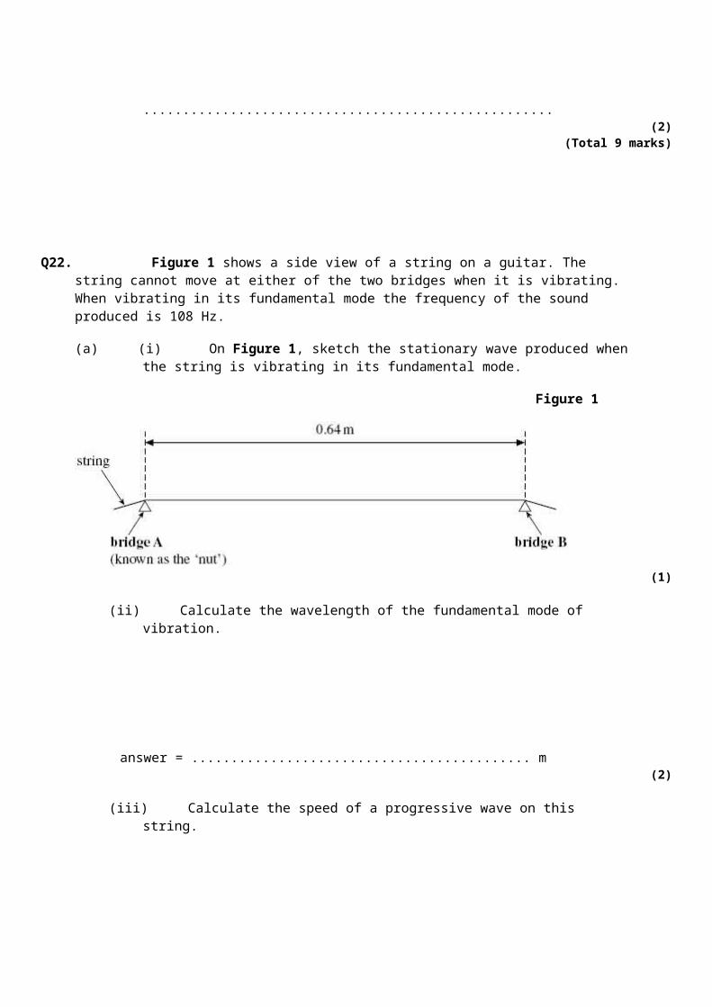
Q22. Figure 1 shows a side view of a string on a guitar. The string cannot move at either of the two bridges when it is vibrating. When vibrating in its fundamental mode the frequency of the sound produced is 108 Hz.
(a) (i) On Figure 1, sketch the stationary wave produced when the string is vibrating in its fundamental mode.
Figure 1
(1)
(ii) Calculate the wavelength of the fundamental mode of vibration.

answer = ........................................... m(2)
(iii) Calculate the speed of a progressive wave on this string.
answer = ...................................... m s–1
(2)
(b) While tuning the guitar, the guitarist produces an overtone that has a node 0.16 m frombridge A.
(i) On Figure 2, sketch the stationary wave produced and label all nodes that are present.
Figure 2
(2)
(ii) Calculate the frequency of the overtone.
answer = ...................................... Hz(1)
(c) The guitarist needs to raise the fundamental frequency of vibration of this string.State one way in which this can be achieved.

......................................................................................................................
......................................................................................................................(1)
(Total 9 marks)
Q23. Just over two hundred years ago Thomas Young demonstrated the interference of light by illuminating two closely spaced narrow slits with light from a single light source.
(a) What did this suggest to Young about the nature of light?
......................................................................................................................
......................................................................................................................(1)
(b) The demonstration can be carried out more conveniently with a laser. A laser producescoherent, monochromatic light.
(i) State what is meant by monochromatic.
.............................................................................................................
.............................................................................................................
(ii) State what is meant by coherent.
.............................................................................................................
.............................................................................................................(2)
(iii) State one safety precaution that should be taken while using a laser.
.............................................................................................................
.............................................................................................................(1)
(c) The diagram below shows the maxima of a two slit interference pattern produced on a screen when a laser was used as a monochromatic light source.

The slit spacing = 0.30 mm.The distance from the slits to the screen = 10.0 m.
Use the diagram above to calculate the wavelength of the light that produced the pattern.
answer = ...................................... m(3)
(d) The laser is replaced by another laser emitting visible light with a shorter wavelength.State and explain how this will affect the spacing of the maxima on the screen.
......................................................................................................................
......................................................................................................................
......................................................................................................................
......................................................................................................................(2)
(Total 9 marks)
Q24. (a) The diagram below represents a progressive wave travelling from left to right on a stretched string.

(i) Calculate the wavelength of the wave.
answer ................................... m(1)
(ii) The frequency of the wave is 22 Hz. Calculate the speed of the wave.
answer............................m s–1
(2)
(iii) State the phase difference between points X and Y on the string, giving an appropriate unit.
answer ..............................(2)
(b) Describe how the displacement of point Y on the string varies in the next half-period.
......................................................................................................................
......................................................................................................................
......................................................................................................................
......................................................................................................................
......................................................................................................................
......................................................................................................................(2)
(Total 7 marks)
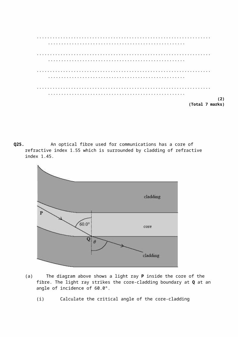
Q25. An optical fibre used for communications has a core of refractive index 1.55 which is surrounded by cladding of refractive index 1.45.

(a) The diagram above shows a light ray P inside the core of the fibre. The light ray strikes the core-cladding boundary at Q at an angle of incidence of 60.0°.
(i) Calculate the critical angle of the core-cladding boundary.
answer ........................... degrees(3)
(ii) State why the light ray enters the cladding at Q.
.............................................................................................................
.............................................................................................................(1)
(iii) Calculate the angle of refraction, θ, at Q.
answer .............................. degrees(3)
(b) Explain why optical fibres used for communications need to have cladding.

......................................................................................................................
......................................................................................................................
......................................................................................................................
......................................................................................................................
......................................................................................................................
......................................................................................................................(2)
(Total 9 marks)
Q26. A narrow beam of monochromatic light of wavelength 590 nm is directed normally at a diffraction grating, as shown in the diagram below.
(a) The grating spacing of the diffraction grating is 1.67 × 10⁻⁶ m.
(i) Calculate the angle of diffraction of the second order diffracted beam.
answer .................................... degrees(4)
(ii) Show that no beams higher than the second order can be observed at this wavelength.
(3)

(b) The light source is replaced by a monochromatic light source of unknown wavelength.A narrow beam of light from this light source is directed normally at the grating.Measurement of the angle of diffraction of the second order beam gives a value of 42.1°.
Calculate the wavelength of this light source.
answer ....................................... m(2)
(Total 9 marks)
Q27. Figure 1 represents a stationary wave formed on a steel string fixed at P and Q when it is plucked at its centre.
Figure 1
(a) Explain why a stationary wave is formed on the string.
......................................................................................................................
......................................................................................................................
......................................................................................................................
......................................................................................................................
......................................................................................................................(3)
(b) (i) The stationary wave in Figure 1 has a frequency of 150 Hz. The string PQ has a length of 1.2 m.Calculate the wave speed of the waves forming the stationary wave.

Answer ........................... m s–1
(2)
(ii) On Figure 2, draw the stationary wave that would be formed on the string at the same tension if it was made to vibrate at a frequency of 450 Hz.
Figure 2
(2)(Total 7 marks)
Q28. The diagram below shows a rectangular glass fish tank containing water. Three light rays, P, Q and R from the same point on a small object O at the bottom of the tank are shown.
(a) (i) Light ray Q is refracted along the water-air surface. The angle of incidence of light ray Q at the water surface is 49.0°. Calculate the refractive index of the water. Give your answer to an appropriate number of significant figures.
Answer ...............................(1)
(ii) Draw on the diagram above the path of light ray P from the water-air surface.(3)
(b) In the diagram above, the angle of incidence of light ray R at the water-air surface is 60.0°.
(i) Explain why this light ray is totally internally reflected at the water surface.
.............................................................................................................
.............................................................................................................(2)
(ii) Draw the path of light ray R from the water surface and explain whether or not Renters the glass at the right-hand side of the tank.
the refractive index of the glass = 1.50
.............................................................................................................
.............................................................................................................
.............................................................................................................
.............................................................................................................
.............................................................................................................
.............................................................................................................
.............................................................................................................
.............................................................................................................(4)
(Total 10 marks)
Q29. A narrow beam of monochromatic red light is directed at a double slit arrangement. Parallel red and dark fringes are seen on the screen shown in the diagram above.
(a) (i) Light passing through each slit spreads out. What is the name for this effect?
.............................................................................................................(1)

(ii) Explain the formation of the fringes seen on the screen.
.............................................................................................................
.............................................................................................................
.............................................................................................................
.............................................................................................................
.............................................................................................................
.............................................................................................................
.............................................................................................................
.............................................................................................................(4)
(iii) The slit spacing was 0.56 mm. The distance across 4 fringe spacings was 3.6 mm when the screen was at a distance of 0.80 m from the slits. Calculate the wavelength of the red light.
Answer ..................... m(4)
(b) Describe how the appearance of the fringes would differ if white light had been used instead of red light.
......................................................................................................................
......................................................................................................................
......................................................................................................................
......................................................................................................................
......................................................................................................................
......................................................................................................................
......................................................................................................................(3)
(Total 12 marks)

Q30. (a) State two requirements for two light sources to be coherent.
......................................................................................................................
......................................................................................................................
......................................................................................................................
......................................................................................................................(2)
(b) Figure 1
Young’s fringes are produced on the screen from the monochromatic source by the arrangement shown in Figure 1.Explain how this arrangement produces interference fringes on the screen. In your answer, explain why slit S should be narrow and why slits S1 and S2 act as coherent sources.The quality of your written answer will be assessed in this question.
......................................................................................................................
......................................................................................................................
......................................................................................................................
......................................................................................................................
......................................................................................................................
......................................................................................................................
......................................................................................................................
......................................................................................................................
......................................................................................................................(6)
(c) The pattern on the screen may be represented as a graph of intensity against position on the screen. The central fringe is shown on the graph in Figure 2. Complete this graph to represent the rest of the pattern by drawing on Figure 2.

Figure 2
(2)(Total 10 marks)
Q31. (a) State and explain two physical properties of the light produced by a laser which makes it different from the light produced by a filament lamp.
Property 1 ....................................................................................................
......................................................................................................................
......................................................................................................................
Property 2 ....................................................................................................
......................................................................................................................
......................................................................................................................(4)
(b) The diagram below shows a cross-section through an optical fibre used for transmitting information. A laser beam, carrying digital data, is incident on the end of the core of the fibre at an angle of incidence i.The core is made from glass of refractive index 1.5.

(i) Complete the graph below to show how the refractive index changes with radial distance along the line ABCD in the diagram, above.
(ii) Calculate the value of the angle of incidence, i, shown in the diagram.
Angle of incidence, i ........................
(iii) Explain how the glass cladding around the optical fibre’s core improves the security of data being transmitted through it and give a reason why this is important.
.............................................................................................................
.............................................................................................................
.............................................................................................................(8)
(Total 12 marks)
Q32. Figure 1 shows a stretched string driven by a vibrator. The right-hand end of a string is fixed to a wall. A stationary wave is produced on the string; the string vibrates in two loops.
Figure 1
(a) State the physical conditions that are necessary for a stationary wave to form on the string.
......................................................................................................................
......................................................................................................................
......................................................................................................................
......................................................................................................................(3)
(b) State how you know that the wave on the string is transverse.
......................................................................................................................(1)
(c) Compare the amplitude and phase of the oscillations of points A and B on the string.
Amplitude ....................................................................................................
Phase ..........................................................................................................(2)
(d) The length of the string is 1.2 m and the speed of the transverse wave on the string is 6.2 m s–1. Calculate the vibration frequency of the vibrator.

Vibration frequency ............................(4)
(e) The frequency of the vibrator is tripled.
(i) Sketch the new shape of the stationary wave on Figure 2.
Figure 2
(ii) Show on your diagram three points, P, Q and R that oscillate in phase.(2)
(Total 12 marks)
Q33. (a) State what is meant by coherent sources of light.
......................................................................................................................
......................................................................................................................
......................................................................................................................
......................................................................................................................(2)
(b)

Figure 1
Young’s fringes are produced on the screen from the monochromatic source by the arrangement shown in Figure 1.
You may be awarded marks for the quality of written communication in your answers.
(i) Explain why slit S should be narrow.
.............................................................................................................
.............................................................................................................
.............................................................................................................
.............................................................................................................
(ii) Why do slits S1 and S2 act as coherent sources?
.............................................................................................................
.............................................................................................................
.............................................................................................................
.............................................................................................................(4)
(c) The pattern on the screen may be represented as a graph of intensity against position on the screen. The central fringe is shown on the graph in Figure 2. Complete this graph to represent the rest of the pattern by drawing on Figure 2.
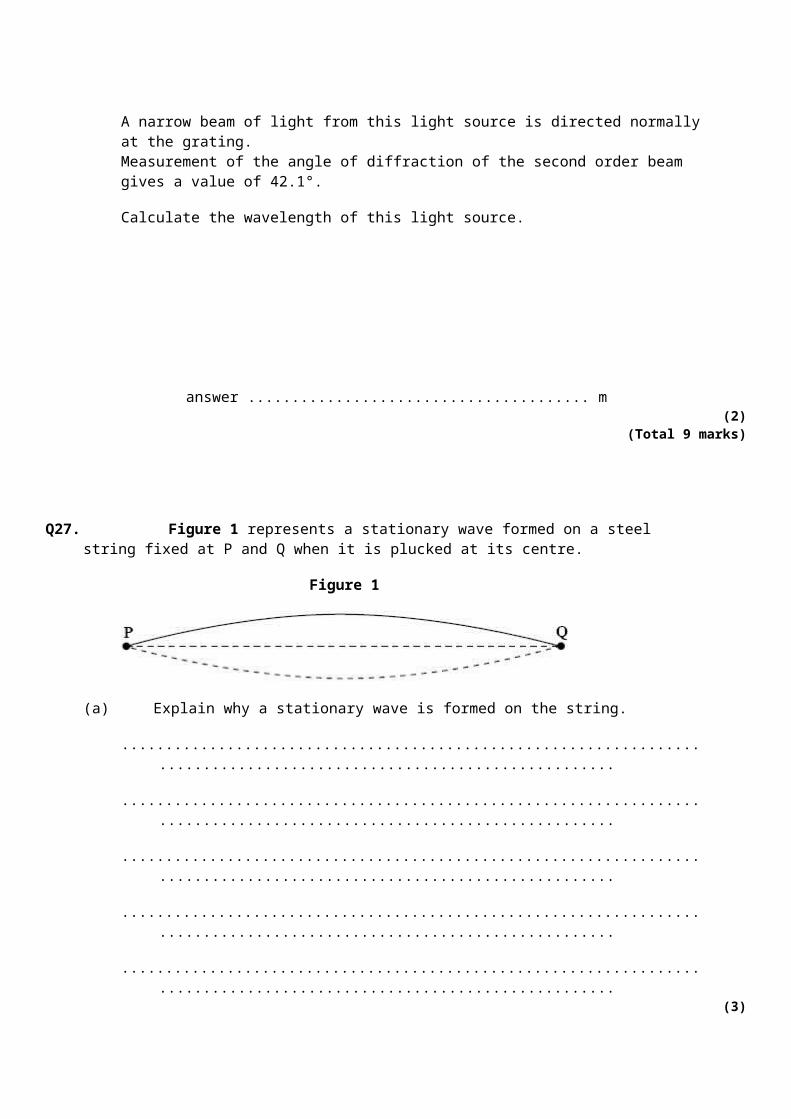
Figure 2(2)
(Total 8 marks)
Q34. (a) State the characteristic features of
(i) longitudinal waves,
.............................................................................................................
.............................................................................................................
(ii) transverse waves.
.............................................................................................................
.............................................................................................................(3)
(b) Daylight passes horizontally through a fixed polarising filter P. An observer views the light emerging through a second polarising filter Q, which may be rotated in a vertical plane about point X as shown in Figure 1.

Figure 1
Describe what the observer would see as Q is rotated slowly through 360°.
You may be awarded marks for the quality of written communication provided in your answer.
......................................................................................................................
......................................................................................................................
......................................................................................................................
......................................................................................................................
......................................................................................................................
......................................................................................................................(2)
(Total 5 marks)
Q35. (a) State the characteristic features of
(i) longitudinal waves,
.............................................................................................................
.............................................................................................................
(ii) transverse waves.
.............................................................................................................
.............................................................................................................(3)
(b) Daylight passes horizontally through a fixed polarising filter P. An observer views the light

emerging through a second polarising filter Q, which may be rotated in a vertical plane about point X as shown in Figure 1.
Figure 1
Describe what the observer would see as Q is rotated slowly through 360°.
You may be awarded marks for the quality of written communication provided in your answer.
......................................................................................................................
......................................................................................................................
......................................................................................................................
......................................................................................................................
......................................................................................................................
......................................................................................................................(2)
(Total 5 marks)
M1.(a) n1 > n2 Allow correct reference to ‘optical density’
(incident) angle > critical angle (allow θc not ‘c’)OR critical angle must be exceeded
Allow nA > nB
Do not allow: ‘angle passes the critical angle’2
(b)

For second mark, don’t allow 1.6 × 10⁸
Allow 1.66 × 10⁸ or 1.70 × 10⁸
Allow 1.6. × 108
(= 1.667 × 10 8) = 1.67 × 10⁸ (ms−1) 2
(c) sin72 = 1.80sin θ
Correct answer on its own gets both marks
θ = 31.895 = 31.9 correct answer >= 2sf seen Do not allow 31 for second markAllow 31.8 − 32
2
(d) 1.80 sin θc=1.40 OR θc = 51.058 = 51.1 ° (accept 51)
Correct answer on its own gets both marksDon’t accept 50 by itself
2
OR = 0.778
(e) (i) 22 + their (c) (22 + 31.9 = 53.9) 53.9 > (51.1) critical angle
If c + 22 < d then TIR expectedIf c + 22 > d then REFRACTION expected
ORc + 22 < their d (θc ) ecf from (c) and (d)angle less than critical angle
Allow max 1 for ‘TIR because angle > critical angle’ only if their d > c + 22
2
(ii) TIR angle correct ecf from e(i) for refraction answer
Tolerance: horizontal line from normal on the right / horizontal line from top of lower arrow.If ei not answered then ecf (d). If ei and d not answered then ecf c
1[11]

M2.(a) (i) π / 2 (radians) or 90 (degrees) No path differencesPenalise contradictionsNo fractions of a cycle
1
(ii) 3π / 2 (rad) or 270 (degrees) No path differencesPenalise contradictionsNo fractions of a cycle
1
(b) (oscillation or motion) perpendicular to direction of wave (travel / velocity / energy transfer) (oscillates from equilibrium to maximum positive displacement, back to equilibrium, then to max negative displacement) and back to equilibrium / starting position / rest position
do not allow ‘up and down’ for first markallow ‘up and down’, or ‘down then up’, ‘side to side’, ‘rise and fall’ in place of oscillatesAllow ‘rest position’, ‘starting position’ ,‘middle’, ‘centre line’ref to nodes / antinodes not allowed for 2 nd mark
2
(c) (the wave is) transverse OR not longitudinal accept it is an S wave or secondary wave
only transverse can be polarised OR longitudinal waves cannot be polarisedOR oscillations are in one plane
2
(d) (i) number of waves / complete cycles / wavelengths (passing a point / produced)per second
or ‘unit time’allow: (number of) oscillations / vibrations / cycles per secondallow f=1 / T only if T is correctly defineddo not allow references to f=c / λ
1
(ii) ( v = f / λ λ = v / f = ) 4.5 × 10³ / 6.0 = 750 (m)
correct answer only gets 2 marks2
[9]
M3.(a) single frequency (or wavelength or photon energy) not single colouraccept ‘very narrow band of frequencies’
1
(b) subsidiary maxima (centre of) peaks further away from centre

For second mark: One square tolerance horizontally. One whole subsid max seen on either side.
subsidiary maxima peaks further away from centre AND central maximum twice width of subsidiaries AND symmetrical
Central higher than subsid and subsid same height + / − 2 squares. Minima on the x axis + / − 1 square.Must see 1 whole subsidiary for second mark
2
(c) ONE FROM:
• don't shine towards a person• avoid (accidental) reflections• wear laser safety goggles• 'laser on' warning light outside room• Stand behind laser• other sensible suggestion
allow green goggles for red laser, ‘high intensity goggles’, etc.not ‘goggles’, ‘sunglasses’
eye / skin damage could occur 2
(d) 3 from 4
• central white (fringe)• each / every / all subsidiary maxima are composed of a spectrum (clearly stated or
implied)• each / every / all subsidiary maxima are composed of a spectrum (clearly stated or
implied) AND (subsidiary maxima) have violet (allow blue) nearest central maximumOR red furthest from centre
• Fringe spacing less / maxima are wider / dark fringes are smaller (or not present)allow ‘white in middle’For second mark do not allow ‘there are colours’ or ‘there is a spectrum’ on their ownAllow ‘rainbow pattern’ instead of spectrum but not ‘a rainbow’Allow ‘rainbow pattern’ instead of spectrum but not ‘a rainbow’If they get the first, the second and third are easier to awardAllow full credit for annotated sketch
3[8]
M4.(a) (n =) OR 0.2436 / 0.1657 working must be seen0.24 / 0.17 = 1.41 is not acceptable
AND ( = 1.4699) = 1.47 given correctly to 3 or more significant figuresWatch for:14.1 / 9.54 = 1.478
1
(b) (i) ray goes along the boundary Deviation by no more than 1mm by the end of the diagram.

(partial) reflection shown (allow dotted or solid line. This mark can be awarded if TIR is shown)
Tolerance: 70° to 85° to normal or labelled e.g. θ and θ, etc2
(ii) (90 − 9.54 = ) 80.46 or 80.5 (° ) ( allow 80° )Don’t allow 81 degrees
1
(iii) (n = nc sin θ)allow 80 or 81 degrees here
= 1.47 sin 80.46° ecf bii
=1.45 (1.4496)Correct answer gains both marks
2
(c) • protect the core (from scratches, stretching or breakage)comment on ‘quality’ of signal is not sufficient
• prevent ‘crossover’ of signal / ensure security of data / prevent loss of information / data / signaldon’t allow ‘leakage’ on its own.
• increase the critical angle / reduce pulse broadening / (modal)dispersion / rays with a small angle of incidence will be refracted out of the coreDon’t allow ‘loss of light’
• increase rate of data transferAllow ‘leakage of signal’, etc
max two correct (from separate bullet points) 2
[8]
M5.Good / Excellent
The candidate’s writing should be legible and the spelling, punctuation and grammar should be sufficiently accurate for the meaning to be clear.The candidate’s answer will be assessed holistically. The answer will be assigned to one of three levels according to the following criteria.
High Level (Good to excellent): 5 or 6 marksThe information conveyed by the answer is clearly organised, logical and coherent, using appropriate specialist vocabulary correctly. The form and style of writing is appropriate to answer the question.
can say disturbance, amplitude or displacement
Mentions:
• (1) waves (meet when) travelling in opposite directions / cross/ wave meets a

reflected wave / etc
• (2) same wavelength (or frequency)
• (3) node – point of minimum or no disturbance
• (4) antinode – point of maximum disturbance / maximum displacement/amplitude occurs
• (5) node - two waves (always) cancel / destructive interference / 180o phase difference (between displacements of the two waves at the node)
• (6) antinode – reinforcement / constructive interference occurs / (displacements) in phase
• (7) mention of superposition of the two waves
5 marks: points (1) AND (2) with three points from (3), (4), (5), (6) or (7)
for 6 marks: points (1) to (6) must be seenlabelled diagram can provide supporting evidence but labels: ‘node’ / ‘antinode’ by themselves cannot replace points 3 and 4
5 / 6
ModestIntermediate Level (Modest to adequate): 3 or 4 marks The information conveyed by the answer may be less well organised and not fully coherent. There is less use of specialist vocabulary, or specialist vocabulary may be used incorrectly. The form and style of writing is less appropriate.
Mentions any 3 of the 7 points.
4 marks: (1) OR (2) AND three others.3 / 4
LimitedLow Level (Poor to limited): 1 or 2 marksThe information conveyed by the answer is poorly organised and may not be relevant or coherent. There is little correct use of specialist vocabulary. The form and style of writing may be only partly appropriate.
One relevant point
OR a relevant, labelled diagram
2 marks: two points OR one point and a relevant labelled diagram1 / 2
[6]
M6.(a) same wavelength / frequency
constant phase relationship allow ‘constant phase difference’ but not ‘in phase’2

(b) (i) ( λ = )Use of speed of sound gets zero
3.00 × 108 = 9.4 (109) λ OR
= 3.2 × 10⁻² (3.19 × 10⁻² m) Allow 0.03
2
(ii) 3.2 × 10⁻² (m) ecf from biDon’t allow ‘1 wavelength’, 1λ, etcDo not accept: zero, 2 , 360 °
1
(c) maximum (at position shown) allow constructive superposition. ‘Addition’ is not enough
constructive interference / reinforcement
ecf for ‘minimum’ or for reference to wrong maximum
(the waves meet) ‘in step’ / peak meets peak / trough meets trough / path difference is (n) λ / in phase
3
(d) s = Don’t allow use of the diagram shown as a scale diagram
ecf biDo not penalise s and w symbols wrong way round in working if answer is correct.
= 0.12 (0.1218 m) Correct answer gains first two marks.
= any 2sf number Independent sf mark for any 2 sf number
3
(e) a maximum Candidates stating ‘ minimum ’ can get second mark only
(f × 2 results in) λ/2
path difference is an even number of multiples of the new wavelength ( 2n λ new )
allow ‘path difference is nλ’ / any even number of multiples of the new λ quoted e.g. ‘path

difference is now 2 λ’3
[14]
M7. (a) (i) cladding 1
(ii) sin θc = 1.41/1.46
θc= 75.0 (°) (74.96) 2
(b) (i) 65 (degrees) 1
(ii) 1.46 sin 65 = 1.41 sin r or sin r = 0.93845 ecf bi
r = 70 (degrees) (69.79) ecf bi2
(c) Two from:
• less light is lost
• better quality signal / less distortion
• increased probability of TIR
• Less change of angle between each reflection
• reflects more times (in a given length of fibre) keeping (incident) anglelarge(r than critical angle)
• (angle of incidence is) less likely to fall below the critical angle
• less refraction out of the core
• improved data transfer / information / data / signal carried quicker
• less multipath dispersion (smearing / overlap of pulses)
2
[8]
M8. (a) (i) oscillates / vibrates
(allow goes up and down / side to side / etc, repeatedly, continuously, etc)
about equilibrium position / perpendicularly to central line 2

(ii) X and Y: antiphase / 180 (degrees out of phase) / п (radians out of phase)
X and Z: in phase / zero (degrees) / 2п (radians) 2
(b) (i) v = fλ
= 780 x 0.32 / 2 or 780 x 0.16 OR 780 x 320 / 2 or 780 x 160
THIS IS AN INDEPENDENT MARK
= 124.8 (m s–1) correct 4 sig fig answer must be seen2
(ii) ¼ cycle
T = 1 / 780 OR = 1.28 × 10⁻³
0.25 × 1.28 × 10–3
= 3.2 × 10⁻⁴ (s)
Allow correct alternative approach using distance of 0.04m
travelled by progressive wave in ¼ cycle divided by speed.
0.04 /125 = 3.2 × 10⁻⁴ (s) 3
(c) (i) antinode 1
(ii) 2 x 0.240
= 0.48 m ‘480m’ gets 1 mark out of 22
(iii) (f = v/λ = 124.8 or 125 / 0.48 ) = 260 (Hz) ecf from cii 1
[13]
M9. (a) (wave) B
(the parts of the) spring oscillate / move back and forth in direction of / parallelto wave travelORmention of compressions and rarefactions
Second mark can only be scored if first mark is scored2

(b) (i) (double ended arrow / line / brackets) from between two points in phase 1
(ii) wave A: arrow vertically upwards
wave B: arrow horizontally to the left 2
(c) (transmitted radio waves are often) polarised
aerial (rods) must be aligned in the same plane (of polarisation / electric field) ofthe wave
2[7]
M10. (a) max three from
central maximum shown
two equally spaced first order maxima
central and one first order labelled correctly
central white maximum
indication of spectra/colours in at least one first order beam
at least one first order beam labelled with violet (indigo or blue) closest to thecentre or red furthest
3
(b) dark/black lines or absorption spectrum or Fraunhofer lines
(reveal the) composition (of the star’s atmosphere)
accept dark ‘bands’
accept atoms or elements in the star
or the peak of intensity
(is related to) the temperature
or Doppler (blue or red) shift
(speed of) rotation or speed of star (relative to Earth) 2
(c) (i) grating and screen shown with both labelled

laser or laser beam labelled 2
(ii) The candidate’s writing should be legible and the spelling, punctuation and grammar should be sufficiently accurate for the meaning to be clear.
The candidate’s answer will be assessed holistically. The answer will be assigned to one of three levels according to the following criteria.
High Level (Good to excellent): 5 or 6 marks
The information conveyed by the answer is clearly organised, logical and coherent, using appropriate specialist vocabulary correctly. The form and styleof writing is appropriate to answer the question.
• correct use of (n)λ = d sin θ
• and measure appropriate angle (eg ‘to first order beam’ is the minimum required)
• and method to measure angle (eg tan θ = x/D, spectrometer, accept protractor)
• and at least one way of improving accuracy/reliability
• for full marks: also explain how d is calculated, eg d = 1/ lines per mm (× 103)
Intermediate Level (Modest to adequate): 3 or 4 marks
The information conveyed by the answer may be less well organised and notfully coherent. There is less use of specialist vocabulary, or specialistvocabulary may be used incorrectly. The form and style of writing is lessappropriate.
• use of (n)λ = d sin θ
• and measure appropriate angle (eg ‘to first order beam’ is the minimum required)
• and method of measurement of θ (eg tan θ = x/D, spectrometer, accept protractor) or at least one way of improving accuracy/reliability
Low Level (Poor to limited): 1 or 2 marks
The information conveyed by the answer is poorly organised and may not berelevant or coherent. There is little correct use of specialist vocabulary. The formand style of writing may be only partly appropriate.
• use of (n)λ = d sin θ
• or measure appropriate angle (eg ‘to first order beam’ is the minimum required)
• or at least one way of improving accuracy/reliability

Incorrect, inappropriate of no response: 0 marks
No answer or answer refers to unrelated, incorrect or inappropriate physics.
The explanation expected in a competent answer should include
Accuracy/reliability points
• measure between more than one order (eg 2 θ)
• measure θ for different orders (for average λ not average angle)
• check or repeat/repeat for different distances (D)
• use of spectrometer
• use large distance to screen (D)
• protractor with 0.5 degree (or less) intervals
• graphical method: plot sin θ against n (gradient = λ/d)6
[13]
M11. (a) (i) sin 56 = nglass sin 30
(nglass = sin56/sin30) (= 1.658) = 1.7 2
(ii) sin θc = 1/1.658 ecf from ai
θc = (37.09 or 37.04) = 37 (degrees)
accept 36 (36.03 degrees) for use of 1.72
(b) TIR from the upper side of the prism ecf from part aii
and correct angle
refraction out of the long edge of the prism away from the normal 2
[6]
M12. (a) the maximum displacement (of the wave or medium)

from the equilibrium position
accept ‘rest position’, ‘undisturbed position’, ‘mean position’2
(b) (vertically) downwards (¼ cycle to maximum negative displacement)
then upwards (¼ cycle to equilibrium position and ¼ cycle to maximumpositive displacement)
down (¼ cycle) to equilibrium position/zero displacement and correctreference to either maximum positive or negative displacement or correctreference to fractions of the cycle
candidate who correctly describes the motion of a knot 180 degrees out ofphase with the one shown can gain maximum two marks(ie knot initially moving upwards)
3
(c) max 3 from
stationary wave formed
by superposition or interference (of two progressive waves)
knot is at a node
waves (always) cancel where the knot is
allow ‘standing wave’3
[8]
M13. (a) decrease
constant
decrease 3
(b)

straight ray (ignore arrow) reflecting to the right
reflected angle = incident angle (accept correct angle labels if reflected angle is outside tolerance)
2
(c) (i) (n = ) use of 3 (× 108) = = 1.47 (1.4706)
(must see 3 sf or more)2
(ii) sin θc = or correct substitution in un-rearranged formula
θc = 80.4 (80.401) (80.3 to 80.54) (≈ 80°) must see 3 sf or more2
(d) angle of refraction = 180 – 90 – 80.4 = 9.6°
sinθ = 147(06) sin 9.6 = 0.25 ecf from first mark
θ = 14 (= 14.194°) ecf from first mark
range 13 to 15° due to use of rounded values3
(e) (reduced amplitude) due to absorption/energy loss(within the fibre)/attenuation/scattering (by the medium)/loss from fibre
(pulse broadening caused by) multi-path (modal) dispersion/different rays/modes propagating at different angles/nonaxial rays take longer time to travel same distance along fibreas axial rays
2[14]
M14. (a) The candidate’s writing should be legible and the spelling, punctuation and grammar should be sufficiently accurate for the meaning to be clear.
The candidate’s answer will be assessed holistically. The answer will be assigned to one of three levels according to the following criteria.
High Level (Good to excellent): 5 or 6 marks
The information conveyed by the answer is clearly organised, logical and coherent, using appropriate specialist vocabulary correctly. The form and style of writing is appropriate to

answer the question.
The candidate provides a comprehensive and coherent description which includes; fringe spacing/separation w and distance D
measured with one instrument named, uses λ = to obtain value for λ,measures distance between several maxima and includes a valid point about safety.
Intermediate Level (Modest to adequate): 3 or 4 marks
The information conveyed by the answer may be less well organisedand not fully coherent. There is less use of specialist vocabulary, or specialist vocabulary may be used incorrectly. The form and style of writing is less appropriate.
The candidate provides an adequate explanation that lacks some of the essential points. The candidate is expected to include; w or ‘fringes’ measured or uses
λ = to obtain value for λ. They include one accuracy point or a valid point about safety.
Low Level (Poor to limited): 1 or 2 marks
The information conveyed by the answer is poorly organised and may not be relevant or coherent. There is little correct use of specialist vocabulary. The form and style of writing may be only partly appropriate.
The candidate provides a limited explanation with no more than one or two valid points.
Incorrect, inappropriate of no response: 0 marks
No answer or answer refers to unrelated, incorrect or inappropriate physics.
The explanation expected in a competent answer should include a coherent selection of the following points.
Measurements
• suitable measuring instrument for w
• suitable measuring instrument for D
Finding the wavelength
• uses λ = to obtain value for λ.• explains graphical approach
Accuracy
• several fringe spaces measured
• centres of fringes used
• five or more fringes/four fringe spaces measured

• large value of D
• D greater than or equal to 2 m
• dark room
• repeat measurements
• vernier calliper for w (not ‘calliper’, not micrometer)
• graphical method varying D and measuring w
• other valid accuracy point
Safety
• avoid shining laser at (or near) a person
• laser safety goggles
• avoid reflections
• warning sign or lightMax 6
(b) (light from both sources has) constant phase relationship / difference
‘in phase’ or ’same wavelength’ or ‘same frequency’ is one mark2
(c) single slit then double slits to the right
single slit and double slits labelled 2
(d)
if candidate refers to white light Young’s fringes with white light;
orif candidate refers to the laser;
contain (different) colours or central white fringe
monochromatic/one colour
less intense more intense
maxima wider/minima narrower ormax or min closer together for white light compared to a red laser
maxima narrower/minima wider ormax or min further apart for a redlaser
fringes/lines/bands etc compared to ‘dots’
‘dots’ for laser compared to ‘bands’ etc
2
from each row, one only max 2

(e) cancellation / waves cancel / destructive interference/destructive superposition
(light from one slit meets light from the other) in antiphase (180 out of phase) or a path difference of ((n+) ½) λ
2[14]
M15. (a) 3 subsidiary maxima in correct positions (1)
intensity decreasing (1)
2
(b) a single wavelength (1)
constant phase relationship/difference (1)2
(c) maxima further apart/central maximum wider/subsidiary maximumwider/maxima are wider (1)
1
(d) wider/increased separation (1)
lower intensity (1)2
(e) distinct fringes shown with subsidiary maxima (1)
indication that colours are present within each subsidiary maxima (1)
blue/violet on the inner edge or red outer for at least one subsidiarymaximum (1)

(middle of) central maximum white (1)3
[10]
M16. The candidate’s writing should be legible and the spelling, punctuationand grammar should be sufficiently accurate for the meaning to be clear.
The candidate’s answer will be assessed holistically. The answer will beassigned to one of the three levels according to the following criteria.
High Level (good to excellent) 5 or 6 marks
The information conveyed by the answer is clearly organised, logical andcoherent, using appropriate specialist vocabulary correctly. The form andstyle of writing is appropriate to answer the question.
Mentions waves travelling in opposite directions or waves of samefrequency (and amplitude) and superpose or interfere or add together.
Intermediate Level (modest to adequate) 3 or 4 marks
The information conveyed by the answer may be less well organised andnot fully coherent. There is less use of specialist vocabulary, or specialistvocabulary may be used incorrectly. The form and style of writing is lessappropriate.
Mentions waves travelling in opposite directions (accept ‘waves reflect/rebound back or from clamp’) or superposition/addition/interference ofwaves or waves of same frequency/wavelength.
Low Level (poor to limited) 1 or 2 marks
The information conveyed by the answer is poorly organised and may notbe relevant or coherent. There is little correct use of specialist vocabulary.The form and style of writing may only be partly appropriate.
One correct key feature or one relevant remark regarding formation given.
The explanation expected in a competent answer should include acoherent account of the following points concerning the physicalprinciples involved and their consequences in this case.
• 4 nodes where there is no movement/zero amplitude
• 3 antinodes where amplitude is maximum
• wavelength 0.80 m
• end antinodes in phase/middle and ends in antiphase

• between node and antinode, amplitude of oscillation increases
• waves reflect off the clamp (and the rod)
• waves travelling in opposite directions superpose/add/interfere
• wave have same wavelength and frequency (similar amplitude)
• always cancellation at nodes/always constructive superposition at antinodes
• energy is not transferred along string[6]
M17. (a) sin θ = or 1.33 sin θ = 1.47 sin44 or sin–1 0.768 (1)
θ = 50.15, 50.2, 50.35 (°) (1)answer seen to > 2 sf
2
(b) refracts towards normal (1) 44° shown (1)2
(c) (TIR) only when ray travels from higher n to lower n or (water to glass) islower n to higher n (1)
do not allow ‘density’, allow ‘optical density’, n or refractive index only
1
(d) sin θc = or 1.47 sin θc = (1 ×) sin90 (1)
θc = 42.86 (= 43.0(°)) (1)2
(e)

2[9]
M18. (a) maximum displacement from equilibrium/meanposition/mid-point/etc (1)
1
(b) (i) any one from:
surface of water/water waves/in ripple tank (1)
rope (1)
slinky clearly qualified as transverse (1)
secondary (‘s’) waves (1)max 1
(ii) transverse wave: oscillation (of medium) is perpendicular to
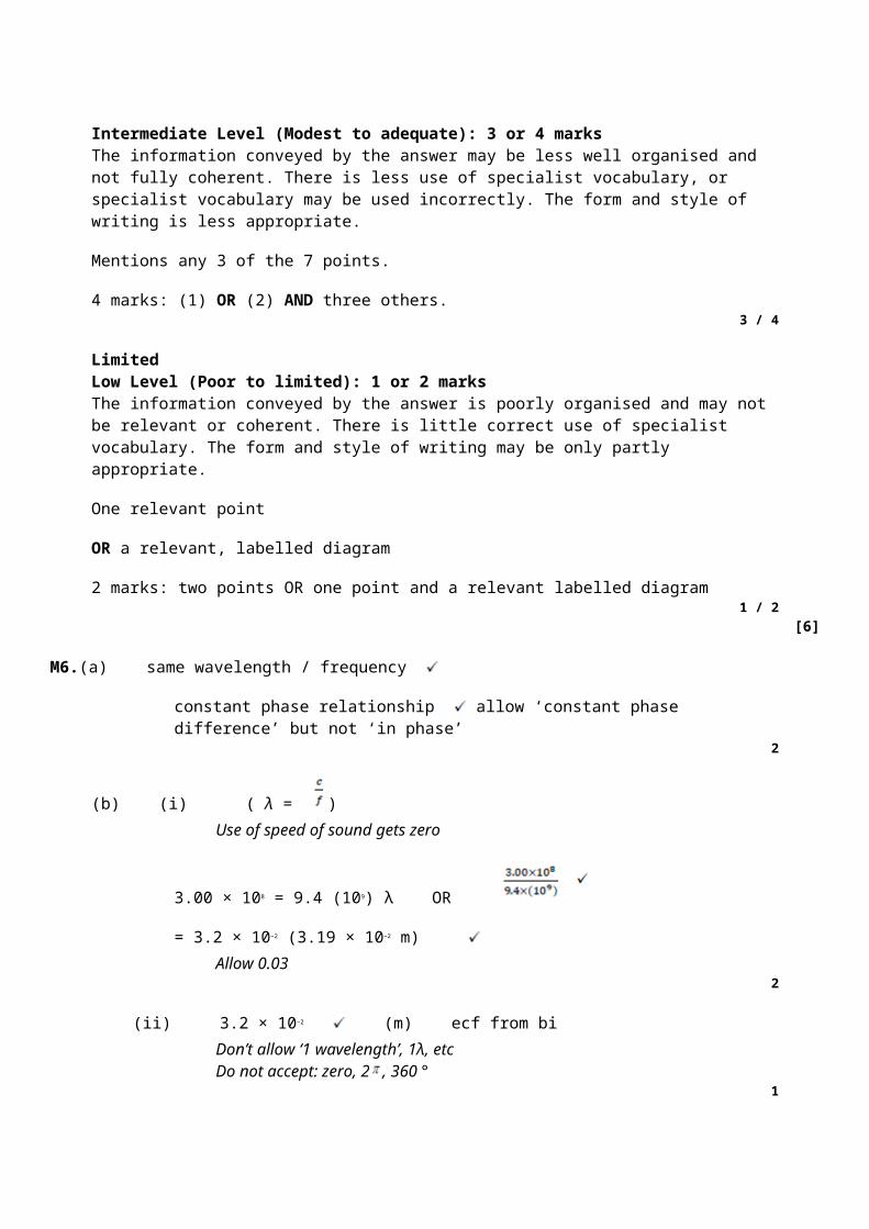
wave travel
or transverse can be polarised
or all longitudinal require a medium (1)1
(c) (i) vertical line on B ± 5° (1)1
(ii)
max 0, 180, 360 + min 90, 270 (1)
and line reaches same minimum and maximum every timeand reasonable shape (1)
2
(d) appropriate use (1)
reason for Polaroid filter being used (1)
eg
Polaroid glasses/sunglasses/ to reduce glare windscreens
camera reduce glare/enhance image
(in a) microscope to identify minerals/rocks
polarimeter to analyse chemicals/concentration or type of sugar
stress analysis reveals areas of high/low stress/ other relevant detail
LCD displays very low power/other relevant

detail
3D glasses enhance viewing experience, etc2
[8]
M19. (a) λ correct (1)
d correct (1) arrow or line needed, both ends extending beyondcentral black line
2
(b) angle θ gets smaller (1)
because path difference gets smaller/d constant, (λ smaller) sosin θ smaller (1)
max 1 for correct explanation for λ increasing2
(c) boxes 1,5,6 (1)(1)
two correct 1 mark
4 ticks max 1
5 or 6 ticks gets 02
(d) (i) 3.3 × 10⁻⁶ m (1) (1/300 = 3.33 × 10⁻³ mm, 3300 nm) DNA 1 sf hereDNA 1/300 000 as answer
accept 3 1/3 × 10–6, 3.33 × 10⁻⁶ recurring, etc1
(ii) (sin θ =) (1)
correct wavelength used and seen (545 to 548 × 10–9)
and 9.4 to 9.6 (°) (1) ecf (d) (i), for correct wavelength only(545 to 548 × 10–9)
2[9]

M20. (a) reflects at correct angle by eye (use top of ‘27’ and bottomof ‘42’ as a guide) or 27° or 63° correctly marked (1)
refracts away from normal at glass/air (1)
symmetrical by eye or refracted angle (42°) correctly markedand at least one normal line added (1)
3
(b) (ng) = (1) DNA 42/27 = 1.56
= 1.47 (1.474) 3 sf shown (1)2
(c) 63 (°) (1)allow 62 to 62.99 with reasoning, allow ‘slightly less than 63’ without reason given
1
(d) = 1.474 sin (c) (1) or use of n = 1.5
= 1.3(1) or 1.34 if n = 1.5 used (1)2
[8]
M21. (a) (i) A: cladding + B: core (1)1
(ii)
refraction towards the normal line (1)
continuous lines + strikes boundary + TIR correct angles byeye + maximum 2 TIRs (1)
2

(b) or = 0.9865 (1)
80.6 or 80.8 or 81 (°) only (1)2
(c) to reduce multipath or multimode dispersion (1)
(which would cause) light travelling at different angles to arrive atdifferent times/pulse broadening/merging of adjacent pulses/’smearing’/poor resolution/lower transmission rate/lower bandwidth/less distancebetween regenerators (1)
or to prevent light/data/signal loss (from core or fibre) (1)
(which would cause) signal to get weaker/attenuation/crossover/datato be less secure (1)
2
(d) correct application (1) (endoscope, cytoscope, arthroscope etc,communications etc)
linked significant benefit stated eg improve medical diagnosis/improvetransmission of data/high speed internet (1)
2[9]
M22. (a) (i) one ‘loop’ (accept single line only, accept single dashed line)
+ nodes at each bridge (± length of arrowhead)
+ antinode at centre (1)1
(ii) λ0 = 2L or λ = 0.64 × 2 (1)
= 1.3 (m) (1) (1.28)2
(iii) (c = f λ) = 108 × (a)(ii) (1)
= 138 to 140(.4) (m s–1) (1) ecf from (a) (ii)2
(b) (i) four antinodes (1) (single or double line)
first node on 0.16 m (within width of arrowhead)
+ middle node between the decimal point and the centre of the

‘m’ in ‘0.64 m’
+ middle 3 nodes labelled ‘N’, ‘n’ or ‘node’ (1)2
(ii) (4 f0 =) 430 (Hz) (1) (432)
or use of f = gives 430 to 440 Hz correct answer only, no ecf1
(c) decrease the length/increase tension/tighten string (1)1
[9]
M23. (a) showed that light was a wave (rather than a particle)/wave nature(of light) (1)
1
(b) (i) single wavelength (or frequency) (1)1
(ii) (waves/source(s) have) constant phase difference (1)1
(iii) any sensible precaution, eg do not look into laser/do not pointthe laser at others/do not let (regular) reflections enter theeye/safety signs/suitable safety goggles (1)
1
(c) (0.16/8) = 0.02(0) (1)
= (1) ecf from calculation of fringe spacing
= 6.0 × 10⁻⁷ m (1) (= 600 nm) ecf from calculation of fringe spacing3
(d) maxima closer together (1)
(quotes equation and states that) spacing is proportional to wavelength/D and s are constant therefore as λ decreases so ω decreases (1)
or links smaller wavelength to smaller path difference (1)2
[9]

M24. (a) (i) 0.4(0) m (1)
(ii) speed ( = frequency × wavelength) = 22 × 0.4(0) ecf (1)= 8.8 (m s–1) (1)
(ii) 90 or 450 (1) ° or degrees (1)or 0.5π or 2.5π or 5π/2 (1) rad(ians)or r or r (1) no R, Rad, etc
5
(b) displacement of Y will be a positive (or ‘up’) maximum at 1/4 of a period (or cycle) (0.0114 s) (1)
returns to original position (at 0.5 of a period or cycle) (owtte) (1)2
[7]
M25. (a) (i) (using n1 sin θ1 = n2 sin θ2 or sin θc = n2/n1 gives)
correct substitution in either equation (eg 1.55 sin c = 1.45 (sin 90)or sin c = 1.45/1.55) (1)
= 0.9355 (accept less sf) (1)c = 69.3(°) (1) (accept 69.4°, 69° or 70°)
(ii) the angle (of incidence) is less than the critical angleor values quoted (1)
(iii) (using n1 sin θ1 = n2 sin θ2 gives)
1.55 sin 60 = 1.45 sin θ (1)
(sin θ = 1.55 sin 60/1.45 =) 0.9258 or 0.926 or 0.93 (1)
θ = 67.8° (1) (accept 68° or 68.4)7
(b) any two from:
keeps signals secure (1)
maintains quality/reduces pulse broadening/smearing (owtte) (1)
it keeps (most) light rays in (the core due to total internal reflectionat the cladding-core boundary) (1)
it prevents scratching of the core (1)

(keeps core away from adjacent fibre cores) so helps to preventcrossover of information/signal/data to other fibres (1)
cladding provides (tensile) strength for fibre/prevents breakage (1)
given that the core needs to be very thin (1)max 2
[9]
M26. (a) (i) = 590 × 10–9m (1)
(using d sin θ = nλ gives)
(1) = 0.707 or
7.07 × 10⁸ if nm used (1)
θ = 45.0° (1) (accept 45°)
(ii) (sin θ ≤ 1) gives ≤ 1 or n ≤ or = (1) = 2.83 (1)
so 3rd order or higher order is not possible (1)
alternative solution:(substituting) n = 3 (into d sin θ = nλ gives) (1)
sin θ ( ) = 1.06 (1)
gives ‘error’/which is not possible (1)7
(b) (using d sin θ = nλ gives)
2 λ = 1.67 × 10⁻⁶ × sin 42.1 (1)
λ(= 0.5 × 1.67 × 10–6 × sin 42.1) = 5.6(0) × 10–7 m (or 560 nm) (1)2
[9]
M27. (a) (progressive waves travel from centre) to ends and reflect (1)

two (progressive) waves travel in opposite directions along the string (1)
waves have the same frequency (or wavelength) (1)
waves have the same (or similar) amplitude (1)
superposition (accept ‘interference’) (1)max 3
(b) (i) wavelength (= 2 × PQ = 2 × 1.20 m) = 2.4 m (1)
speed (= wavelength × frequency = 2.4 × 150) = 360 m s–1 (1)
(answer only gets both marks)
(ii) diagram to show three ‘loops’ (1) and of equal length andgood shape (1) (or loop of one third length (1))
4[7]
M28. (a) (i) (refractive index of water = 1/sin 49.0) = 1.33 (not 1.3 or 1.325) (1)
(ii) ray P shown in the air to right of vertical (1)
refracted away from the normal in the correct direction (1)
correct partial reflection shown (1)4
(b) (i) critical angle for water-air boundary = 49.0°or angle of (incidence of) Q is θc (1)
the angle of incidence (of R) exceeds the critical angle (1)
(ii) the figure shows that R undergoes TIR at water surface andstrikes the glass side (1)
angle of incidence at glass side = 30° (1)
R enters the glass and refracts towards the normal (1)
because ng > nw (1) (or water is optically less dense than glass)
(calculates angle = 26.2° gets last two marks)6
[10]

M29. (a) (i) diffraction (1)
(ii) any 4 points from
interference (fringes formed) (1)
where light from the two slits overlaps (or superposes) (1)
bright (or red) fringes are formed where light (from the twoslits) reinforces (or interfere constructively/crest meets crest) (1)
dark fringes are formed where light (from the two slits)cancels (or interferes destructively/trough meets crest) (1)
the light (from the two slits) is coherent (1)
eitherreinforcement occurs where light waves are in phase(or path difference = whole number of wavelengths) (1)
orcancellation occurs where light waves are out of phase of 180°(in anti-phase)(or path difference = whole number + 0.5 wavelengths) (1)(not ‘out of phase’)
(iii) gives λ = (1)
w (= 3.6/4) = 0.9(0) mm (1) (failure to /4 is max 2)
λ (1) = 6.3 × 10⁻⁷ m (1)9
(b) central (bright) fringe would be white (1)
side fringes are (continuous) spectra (1)
(dark) fringes would be closer together (because λred > average λwhite) (1)
the bright fringes would be blue on the side nearest the centre(or red on the side away from the centre) (1)
bright fringes merge away from centre (1)
bright fringes wider (or dark fringes narrower) (1)max 3
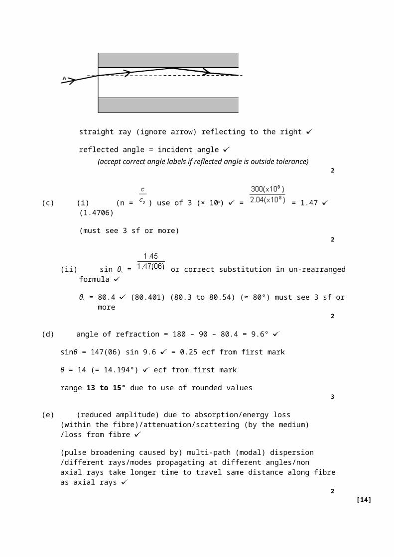
[12]
M30. (a) same wavelength or frequency (1)
same phase or constant phase difference (1)2
(b) The marking scheme for this part of the question includes an overallassessment for the Quality of Written Communication (QWC).There are no discrete marks for the assessment of QWC but thecandidates’ QWC in this answer will be one of the criteria usedto assign a level and award the marks for this part of the question.
Level Descriptoran answer will be expected to meet most of the criteria in the
level descriptor
Mark range
Good 3 – answer includes a good attempt at the explanations required
– answer makes good use of physics ideas including knowledge beyond that given in the question
– explanation well structured with minimal repetition or irrelevant points and uses appropriate scientific language
– accurate and logical expression of ideas with only minor/occasional errors of grammar, punctuation and spelling
5-6
Modest 2 – answer includes some attempts at the explanations required
– answer makes use of physics ideas referred to in the question but is limited to these
– explanation has some structure but may not be complete
– explanation has reasonable clarity but has a few errors of grammar and/or punctuation and spelling
3-4
Limited 1 – answer includes some valid ideas but these are not organised in a logical or clear explanation
– answer lacks structure
– several errors in grammar, punctuation and spelling
1-2
0 – incorrect, inappropriate or no response 0
the explanations expected in a competent answer should include a coherent selection of the following physics ideas:

• narrow single slit gives wide diffraction
• to ensure that both S1 and S2 are illuminated
• slit S acts as a point source
• narrow single slit ensures it provides coherent sources of light atS1 and S2
• S1 and S2 are illuminated by same source giving same wavelength
• paths to S1 and S2 are of constant length giving constant phasedifference or SS1 and SS2 so waves are in phase
• light is diffracted as it passes through S1 and S2 and the diffractedwaves overlap and interfere
• where the path lengths from S1 and S2 to the screen differ bywhole numbers, n of wavelengths, constructive interferenceoccurs producing a bright fringe on the screen
• where the path lengths differ by (n + ½) wavelengths, destructiveinterference occurs producing a dark fringe on the screen
(c) graph to show: maxima of similar intensity to central maximum (1) (or some decrease in intensity outwards from centre)
all fringes same width as central fringe (1)2
[10]
M31. (a) property (of laser light) explanation
monochromatic waves of single frequency/wavelength
collimated produces an approximately parallel beam
coherent waves produced are in constant phase
polarised vibrations in 1 plane only
two correct properties (1)(1)
each correct explanation (1)(1)(if explanation contradicts property, no mark for explanation)
4
(b) (i) stepped graph: n = 1.5 A to B (1)
n lower and constant between 1.5 and 1.0 B to C (1)

n constant at 1.0: C to D (1)
(ii) 1.5 = (1) i = 15(.1)º (1)
(iii) light does not enter the claddingso cannot pass across from one fibre to a neighbouring fibre (1)
fibres without cladding can allow light to pass between fibreswhen the surface of the fibre becomes scratched or moisturelinks two adjacent fibres optically (1)
personal data (such as bank account information) must betransmitted along fibres from which there is no danger ofleakage of light resulting in a breach of security (1)
8[12]
M32. (a) reflection (or 2 waves travelling in opposite directions) (1)
waves have similar amplitudes (1)
waves have similar frequency (1)
reflected wave loses only a little energy at the wall (1)max 3
(b) displacement perpendicular to rest position of the string (1)1
(c) A larger than B (1)
A 180° out of phase with B (1)2
(d) λ = 1.2m (1)
c = f λ (1)
f = 6.2/1.2 (1) 5.2Hz (1)4
(e) (i) diagram correct: 6 loops (1)
(ii) Q and R correct (1)2
[12]

M33. (a) same wavelength or frequency (1)(same phase or) constant phase difference (1)
2
(b) (i) narrow slit gives wide diffraction (1)(to ensure that) both S1 and S2 are illuminated (1)
(ii) slit S acts as a point source (1)S1 and S2 are illuminated from same source givingmonochromatic/same λ (1)paths to S1 and S2 are of constant length giving constant phasedifference (1)[or SS1 = SS2 so waves are in phase]
Max 4QWC 1
(c) graph to show:maxima of similar intensity to central maximum (1)[or some decrease in intensity outwards from centre]all fringes same width as central fringe (1)
2[8]
M34. (a) (i) particle vibration (or disturbance or oscillation) (1)same as (or parallel to) direction of propagation(or energy transfer) (1)
(ii) (particle vibration)perpendicular to direction of propagation (or energy transfer) (1)
3
(b) variation in intensity between max and min (or light and dark) (1)two maxima (or two minima) in 360° rotation (1)
2QWC 1
[5]
M35. (a) (i) particle vibration (or disturbance or oscillation) (1)same as (or parallel to) direction of propagation(or energy transfer) (1)
(ii) (particle vibration)perpendicular to direction of propagation (or energy transfer) (1)

3
(b) variation in intensity between max and min (or light and dark) (1)two maxima (or two minima) in 360° rotation (1)
2QWC 1
[5]
E1.(a) This was perhaps not as well understood as could be expected. There was some use of ‘dense’ rather than ‘optically dense’ and this was not accepted. There was also confusion with many over whether the incident angle should be greater than or less than the critical angle in order for TIR to take place.
(b) Most candidates were successful on this, but a few truncated to 1.6 × 10⁸.
(c) This was very well done. Some rounded or truncated 0.52836 to 0.52 or 0.53 which led to a rounding error in the answer. Only a few did not put a 2 or 3 significant figure answer.
(d) This was also very well done but again some problems with rounding or truncating, e.g. 1.4 / 1.8 = 0.78 or 0.77. Rounding to 2 sf should only be done for the final answer.
(e) (i) There was quite a lot of confusion on this one. Some candidates correctly calculated the incident angle of 54° but then went on to explain that this is less than the critical angle of 51° that they correctly calculated in (d). A common incorrect answer was: ‘It enters glass C because the angle is greater than the critical angle’.
Some candidates do not realise that a calculation can be used to answer a question like this and they instead reasoned that ‘glass C has a lower refractive index, therefore the ray will refract away from the normal’.
Many thought the angle of incidence was 31.9° forgetting to add 22° to this. Some gained only 1 mark because they did not quote the incident angle in their answer.
(ii) Again, some careless lines were drawn. Rulers were often not used, and incident and reflected angles were often very different. To get within the examiners tolerance it is a good idea for students to use a protractor.
E2.(a) (i) Some candidates thought this was a stationary wave and thus stated incorrect phase differences. See (a)(ii).
(ii) Phase difference is generally not well understood by candidates. Phase differences were often wrongly given in fractions of a wavelength e.g. λ / 4 rather than angles, e.g. 90°. Ninety degrees was often also given as π / 4 radians or π radians rather than π / 2 radians. Two hundred and seventy degrees was often thought to be equivalent to π rather than 3 / 2 π radians.
Many said ‘in phase’ or ‘out of phase’ rather than stating the phase difference.
Many marks were lost here due to contradictions, where candidates attempting to

embellish their answers only succeeded in talking themselves out of the mark. E.g.’90° (π / 4)’ or ‘90° (antiphase)’. Where a question says ‘state’ and there is one mark available, the candidate should try to give just the answer that they are confident is correct and not try to expand upon it.
(b) A high proportion of candidates thought that point B was going to go ‘downwards’. Candidates must be clearer when stating directions. It is always advisable to say ‘vertically upwards’ or ‘move upwards perpendicularly to the equilibrium line’. When a description of a complete cycle is required, marks will be lost if the whole cycle is not described including, in this case, the return to the equilibrium position.
(c) Many came up with interesting hypotheses such as, that the wave must have passed through a ‘crack’ in the rock to become polarised. However, in a question like this we are only expecting the candidate to apply the physics that they know. Here we were only looking for the link between polarisation and transverse waves, and not an in depth knowledge of seismology.
(d) This was very well done. A few candidates defined time period (T) rather than frequency. There was a tendency for some to say ‘number of waves that pass a point in a given time’ rather than per second. A rather odd response to this question that was seen quite often was: ‘The frequency doesn’t change’. Quite a few stated the equation f = c/λ but this is not the accepted definition of frequency.
E3.(a) In general, this was a well answered question apart from a tendency for candidates to add extra detail, e.g. ‘single wavelength and coherent’; this loses the mark. As does:‘single wavelength / colour’; because this implies that monochromatic could be just a single colour. However, ‘light of a single wavelength and therefore a single colour’ would be acceptable. It is therefore best to learn the appropriate definition and not add any further detail.
(b) Many candidates did not know what to do on this question.
The red light subsidiary maxima were often shown closer to the central maximum than the blue.
Perhaps single slit diffraction tends to be a little overlooked because the specification does not require any mathematical description. Nevertheless, students should be shown images of the single slit pattern and how it changes for different wavelengths. Images are readily available on the internet via any search engine.
(c) When talking about laser safety, it is not acceptable to say simply ‘wear goggles’. One must say ‘laser safety goggles’, ‘laser safety glasses’, or ‘laser safety eyewear’. Standard laboratory goggles would not afford any significant protection against laser light.
(d) Only a few candidates were able to describe the pattern accurately. Answers tended to be vague and ambiguous. Only a small number decided to add a sketch to clarify their answer and this approach should be encouraged. Again, perhaps the single slit has been overlooked by some in favour of the ‘more difficult’ double slit and grating.
E4.(a) This was a relatively easy question of a type that usually yields high marks. However, this produced a surprising number of wrong answers. A common error was to misinterpretn = c / cs as a ratio of angles and use it to justify dividing 14.1° by 9.54°.
(b) (i) Very few candidates showed the partial reflection and there was a mark available for

this.
(ii) In this question many candidates wrongly used critical angle = sin 1 / 1.47 (= 42.84). Perhaps because they didn’t have the n for the cladding they used n = 1. However, this would have given the critical angle for the air / core. Another common error was to think that the critical angle was 9.54°.
(iii) Again, many candidates chose the first equation they saw (n = c / cs) and substituted angles instead of speeds.
E5.This was a very accessible question given that there are several past paper questions that address the same issue of the formation of stationary waves.
Candidates did very well on this question but there was a lack of understanding of some wave terminology evident. Candidates often correctly explained that two progressive waves travelling in opposite directions give rise to a stationary wave. However, they often described the waves as having a constant phase difference and being coherent. Many also thought that a node is formed by a peak cancelling a trough and an antinode is formed by a peak meeting peak or a trough meeting a trough.
An antinode is formed at a position where the displacements of the two waves are always in the same direction and of equal magnitude, they are not always peaks or troughs. A node is formed where the waves always cancel and this is not only due to a peak meeting a trough but is due to the waves having equal and opposite displacements at the position of the node. Another common misconception was that two troughs meet to give destructive interference.
The two progressive waves have a constantly varying phase difference. It would be correct to say that at the position of a node, the two waves are always in antiphase and they arrive at antinode in phase.
E6.(a) The explanation of coherent should include ‘constant phase relationship’ and ‘same frequency’. Many only picked up one mark for stating one of these. Many said that the waves were ‘in phase’ which was not enough for the mark.
(b) (i) Some did not realise that the speed of light was given on the data sheet. There were many mistakes with the powers of ten; ‘M’ was often interpreted as 106 , 1012 or even 1015.
(ii) Many did not attempt this. Some may have run out of time but many did not understand the concept of path difference.
(c) Some felt that although the waves arrived in phase, the point where they meet is ‘zero displacement’ for both of them and therefore gives a zero reading.
Nodes and antinodes were often referred to as the peaks / troughs and points of zero displacement on a progressive wave, e.g. two troughs meet to give destructive interference. Nodes and antinodes were often mixed up – ‘anti’ wrongly associated with ‘minimum’ perhaps?
(d) Quite a few did not express their answer to 2sf, believing that 3sf was appropriate or that 2 d.p. was required.
To help students remember to address the significant figure issue, one could advise them to draw a line between the instruction: ‘...appropriate number of significant figures’ and the

answer line as soon as they read it in the question.
If the student is uncertain about which symbol represents slit separation and which represents fringe spacing, they may still get the right answer and this was not penalised. However, it is essential that s and D are not interchanged and this mistake led to many candidates failing to access 2 of the marks.
E7. In part (a)(i) a significant number of students did not know ‘cladding’ and in part (a)(ii) the majority got this one correct. However, a significant number had their calculators in radians mode and gained 1 mark for the correct working but got a wrong answer of 1.31. Some rounded prematurely (eg 1.41/1.46 = 0.97 which leads to an answer of 76° rather than 75°). When using the inverse sine function it is important that the value used has not been rounded to less than 4sf.
Quite a few students gave an answer of 85−30 = 55° or 90−30 = 60° for part (b)(i). In part (b)(ii) most students do very well on Snell’s law questions. Those who got the wrong answer for (b)(i) often got full marks here with the error carried forward taken into account. Some did get the refractive indices the wrong way round or omitted the 1.46 – presumably thinking they were calculating a critical angle for a glass / air boundary.
In part (c) many students thought that rays would refract ‘when the critical angle is exceeded’; perhaps associating a large angle with being ‘too big’. Many thought that a ray will travel further in a wide core. It will actually travel the same distance if the angle is the same.
E8. Part (a)(i) was almost universally misinterpreted due to a similar question appearing on a previous paper. Many students interpreted the question as ‘describe the motion over the next cycle’. Those who did this often failed to point out that there was a continuing oscillation taking place. Part (a)(ii) was very poorly answered which was a surprise. A common answer was ‘out of phase’ for X and Y which is not equivalent to ‘antiphase’. Phase was often given in terms of number of wavelengths, e.g. ½λ. There was little understanding of the difference between phase difference along a progressive wave and a stationary wave. Many had measured the fraction of a wavelength between the points and converted this into an angle as you would for a progressive wave. It is suggested that phase difference along a stationary wave be demonstrated by referring to the many simulations available.
Part (b)(i) presented few problems for students. In part (b)(ii) many students did 1/780 and obtained the time for one complete cycle but did not recognise that they needed to divide by 4 to get the time for ¼ of a cycle. A significant number thought that the time between maximum displacement and reaching the equilibrium position was half a cycle. Some divided 780 by 4 which makes the answer 8 times greater than it should be.
For part (c)(i) most students got ‘antinode’ but a significant number put ‘node’/ ‘amplitude’/ ‘max displacement’ / ‘stationary wave’ / ‘equilibrium’ / ‘maxima’. Part (c)(ii) presented few problems for students. In part (c)(iii) quite a few students left this blank because they were unable to answer the previous question. However, many of those who scored the mark did so by using an incorrect answer to (c)(ii). Students should be encouraged not to give up; the final part of a question is not necessarily the hardest.

E9. Most did well in part (b)(i) and indicated a complete wavelength very precisely, though a generous tolerance was allowed. A significant number thought the coils constituted the waveform and gave the spacing between one or two coils as the wavelength and some chose the compression or the rarefaction or the whole length of the spring. In part (b)(ii) many believed point P would move downwards. This is a very common misconception and a similar question has appeared in a past paper. The behaviour of point Q is more difficult to understand. The particle changes direction when the centre of a rarefaction or compression reaches it. If the wave is moving to the right, then as the compression gets closer to the particle, the particle will move left towards the compression.
In (c) the majority of students surprisingly did not recognise that this was about polarisation. Those who did point this out did not describe the aerial being aligned with the plane of polarisation.
E10. Part (a) was done well by most students. However, many would have benefitted from using a protractor to get the angles between the zero order and the two first-order beams roughly equal.
In part (b), the basic requirement is that students know that dark lines (absorption lines) are seen on the spectra from stars and that these reveal elements present in the outer layers of the star. The mark scheme also credited other uses of a stars spectrum. Many students had the idea that spectral lines revealed elements but few knew about absorption lines. This is an area where students who have taken PHYA1 first may have an advantage since they have studied atomic energy levels and may have seen absorption spectra.
Labelling a laser, diffraction grating and some sort of screen or suitable detector was all that was required for the two marks in part (c) (i). Many students missed out the screen. Some had double slits instead of a grating.
Part (c) (ii) was, in general, poorly answered. Many students did not seem to be familiar with this practical and instead described a two-slit approach to measuring wavelength. Those who seemed familiar with the procedure tended not to fully answer the question which asked for details of all the measurements and necessary calculations. The candidate who leaves out these details is unlikely to be able to score more than two marks out of six even if they have given a reasonable general description of the experiment. For example, they must include details of how the angle is to be measured eg by measuring the distance between the zero order and the first-order beam (using a ruler) and the distance between the screen and the grating. They must then use tan θ = O/A to calculate the angle. Where students knew which equation to use, they tended to know insufficient detail to score more than a few marks. Of those students who did describe the use of a grating, many did not know the meanings of the symbols in the equation eg, d was often thought to be the distance between grating and screen and n, the number of lines per mm or even the refractive index of air. Many described measuring the grating spacing with micrometers or metre rules, forgetting that the question stated that the lines per mm are known.
In short, many of the students who took this exam seemed poorly prepared for this type of

question. They were, in some cases, able to produce an answer from a past paper for a closely related, but significantly different, question. Many seemed unaware of the style and quality of answer expected.
Most answers were vague, the literacy level was generally poor and there was a lack of detail regarding the measurements and what should be done with them. This is often the case in the January examination, but it is possible to improve the necessary skills even in the short preparation time available. A few structured lessons on answering this type of question can to be incorporated into schemes of work, allowing students to be fully aware of the expectations.
E11. Most students got the answer to part (a) (i) correct. However, examiners were looking for correct rounding and some students lost a mark for 1.6 or 1.65. A common incorrect approach was to select the equation with the ratio of speeds and use the two angles instead of speeds.
Most students were also correct in part (a) (ii). These questions always yield high marks.
Part (b) was quite poorly answered. Rays were not drawn carefully enough. It can be difficult to draw angles well without a protractor. A protractor is often useful for PHYA2. Students who cannot judge equal angles approximately by eye should be encouraged to use a protractor. The slanted edge of the prism in this question makes the judgement more difficult than usual. In this question students lose the mark if their line is more than five degrees from the true angle. Many students thought that the ray would refract rather than undergo total internal reflection even though they had calculated the correct critical angle. Many showed the refracted rays bending towards the normal rather than away.
E12. Many students had learned the correct definition in part (a) but some gave a description, for example ‘the greatest height of the wave from the middle’. This did not gain marks.
Surprisingly in answer to part (b), many students referred to the equilibrium position as the ‘node’ and maximum amplitude as the ‘antinode’ on a progressive wave. Many use fractions of a cycle to describe the position of the knot but some use angles or fractions of a wavelength which are not appropriate. The biggest loss of marks occurred in the first mark where a large number thought that the knot would be travelling upwards initially.
Part (c) was a fairly easy question with students only needing to state that the ‘knot is at a node on a stationary wave which is caused by superposition’ to get three marks. Most students managed to get two of the marking points. Many did not understand how a node is formed, believing it is the sum of a peak and a trough only, or that the whole rope is stationary, or that the rope is only stationary at a node when cancellation occurs between waves that are 180° out of phase. The two waves that form a stationary wave are not always 180° out of phase in order to cancel at the nodes. Nodes are where the wave always cancels but the phase difference between the waves repeatedly varies from zero to 2π. Cancellation everywhere on the stationary wave only occurs when the waves are in antiphase but cancellation always happens at the nodes because the displacements of the waves are always equal and opposite at those points

(or displacements are both zero when in phase and in antiphase). This is a complex situation but there are many simulations available on the internet that help to get these ideas across.
E13. In part (a) relatively few candidates knew that the frequency remains constant when refraction takes place.
Most drew the ray very well in answer to part (b) and the widespread use of a ruler showed a significant improvement over similar questions in previous examinations. However, a large number did not attempt the question. Those who dropped one mark tended to do so because their ray had a reflected angle that was far too big. Though it is not necessary to use a protractor to gain this accuracy mark, it should be encouraged for those who find it hard to make a good approximation by eye.
Part (d) was a little bit more difficult than previous, similar questions in that the angle of refraction had to be calculated (90 – 80.4 = 9.6°) prior to finding the incident angle. This confused a large number of candidates. Among those who did know what to do, a surprisingly common error was to use 100° for a right angle rather than 90°.
Candidates tended to focus on one cause of loss in answer to part (e), either ‘multipath dispersion’ or ‘attenuation due to energy loss from the pulse’. This meant they accessed only one of the two marks available. Some guesswork was evident in responses to this question. Some candidates explained that the pulse had its amplitude reduced and length increased in order to fit inside the narrow fibre – ‘the fibre is too thin to let the high amplitude through’ was a typical answer. Other common responses were that the wavelength increased when the light entered the glass (presumably the pulse was interpreted as a waveform) or the lower speed of light in glass caused the broadening effect.
E14. Part (a), an extended answer question, yielded the highest marks of any so far on this examination. It was a standard situation and candidates were very familiar with the physics so, the majority gained more than half marks. It was not too difficult to get five marks out of six however; full marks were only given to the most complete of responses.
It was pleasing that only a few misinterpreted the question and chose the wrong path; inappropriate discussion of ‘gratings’ was only seen a few times. The majority of candidates still recommend protecting the eyes from laser radiation by wearing ‘goggles’. If the candidate insists on giving this advice, they must specify ‘goggles designed to protect the eyes from laser radiation’ or words to that effect, since ordinary lab goggles would provide no protection.
Marks were still sometimes lost due to candidates not specifying measuring instruments. However, there was a marked improvement on previous experimental description questions. Even the humble ‘ruler’ should be specified if it is to be used.
Part (b) was a common question and perhaps, therefore, it should have yielded a higher percentage of full-marks answers. The most common error was to say that the two sources are

‘in phase’. However, it should be stressed that coherent sources have a fixed phase relationship, so they are not necessarily in phase.
Many candidates did not include the single slit and many did not label the slits in answer to part (c).
A significant number did not attempt the question at all. Surprisingly, less than half scored any marks at all on this question.
In part (d), some candidates thought that the fringes for white light would be further apart. This would only be true if the laser were red; the candidate would have to state this assumption to gain the mark.
Some lost marks because they did not make it clear which light source they were referring to.
Most candidates gained the mark in part (e) for mentioning destructive interference but did not go on to explain that the cancellation is caused by the waves meeting in antiphase or with half a wavelength path difference.
E15. Most candidates gained at least one mark in part (a) for showing that the intensity of peaks reduced with distance from the centre. However, many did not recall the key difference between the pattern for single and double slits – the single slit pattern has a central maximum which is double the width of the subsidiary maxima.
There were many correct definitions of monochromatic and coherent in part (b). A few stated ‘same colour’ for monochromatic and ‘in phase’ for coherent. Neither of these were accepted.
In part (c), many candidates incorrectly used the equation for two slits to show that the maxima were further apart. This was not penalised since an explanation was not asked for.
Many candidates got part (d) the wrong way around, saying that the fringes would be more closely spaced and more intense. There seemed to be some guess work evident here. Candidates need to be able to describe the appearance of the single slit pattern and be aware of how it will change for different wavelengths, slit widths and for monochromatic and white light. Some teachers introduce the equation for the single slit although it is not in the specification. This is not necessary but can certainly help the more mathematically minded students. To illustrate the change in the pattern, a simple demonstration can be carried out with a red and a green laser shone through the same slit onto a screen.
A pleasing number of candidates produced very detailed and high quality answers to part (e), with many gaining all three marks. Some drew a graph of intensity, which did not gain a mark on its own.
E16. Some candidates forgot to answer the second part of the question and did not make adequate reference to the features of the stationary wave shown. The first part (how a stationary wave is formed) was answered well. Many candidates used the term ‘superimpose’ instead of

‘superpose’ and typically a candidate would lose a mark for this.
E17. There were very few mistakes on part (a). Most candidates correctly showed their answer to more than two significant figures, which was required here. Where one mark was lost it was usually for only giving the answer as 50 rather than 50.15.
For part (c), many candidates wrongly stated that there was no TIR because the angle was below the critical angle. Candidates had to use the term refractive index or optical density. Use of ‘density’ by itself was not given credit.
Part (d) was done very well by the majority of candidates. The most common error was to calculate sin = 1.33/1.47 for the glass/water boundary rather than the glass/air.
In part (e), the most common answer was to assume that the ray refracts out of the glass and into the air. Even candidates who correctly calculated the critical angle as 43 degrees did not realise that the ray is one degree beyond the critical angle. Most candidates who correctly showed the ray reflecting did not then show the ray continuing into the water.
E18. In part (a), the strict definition of amplitude was expected. Candidates needed to say ‘maximum displacement’ and then indicate in some way that this was relative to the equilibrium position.
The majority, however, chose to define amplitude as the distance between the centre and the peak.
For part (b) (i), the majority of candidates could not give an example of a transverse wave other than electromagnetic waves. Most gave a form of electromagnetic radiation (most commonly ‘light’) or even sound. Common answers that were accepted included ‘water waves’, ‘waves on strings’ or ‘s-waves’.
Most candidates realised that a comparison between the direction of wave travel and the oscillation of the medium was a good way to answer part (b) (ii). It was common, however, for candidates to struggle to express this clearly. The most common error was to say that a transverse wave ‘moves’ perpendicular to the direction of wave travel rather than ‘oscillation is perpendicular to direction of wave travel’.
The vast majority of candidates found part (c) (ii) very straight forward.
The majority of candidates had no problem with part (c) (ii). The exact shape of the line was not important as long as the maximum and minimum intensities appeared in the right place.
There were many very good answers to part (d), such as ‘sunglasses/ski goggles reduce glare from light reflected from water/snow’ and ‘a camera filter reduces unwanted reflections’. Common inadequate responses included saying that polarising sunglasses ‘reduce light intensity’ because the lenses are ‘darker’, or that polarising filters reduce UV.

E19. Many candidates did not seem at all familiar with the use of this diagram in the derivation of the grating equation in part (a) and the placing of the labels was often completely random. A large number did not attempt to label the diagram and half of all candidates did not score any marks.
Many who scored one mark had labelled the wavelength correctly but did not accurately indicate the ‘line spacing’ with a suitable arrow or line.
Most candidates gained the first mark in part (b) for realising that sin θ decreased so θ would decrease. Many candidates failed to gain the second mark by not stating that d remained constant. Very few candidates attempted to explain in terms of path difference.
The majority of candidates had no problem matching up the spectral lines in part (c).
In part (d) (i), about half of all candidates were unable to convert lines per mm to line spacing and there was considerable confusion with powers of ten. Many candidates did not convert to metres and many also rounded to one significant figure.
In part (d) (ii) it was expected that the candidate would read an accurate value off the scale.
However, many chose a value to the nearest 10 nm, typically 550 nm. In this situation, it is always best to interpolate when reading off the scale. The uncertainty in this reading can then be expressed by giving the final answer to two significant figures. Line P is somewhere between 545 and 548 nm.
E20. Part (a) states that reflection occurs. However, half of all candidates were unable to show the ray of light reflecting from the glass-liquid surface. Those who did do this tended to also get the second mark for showing the ray refracting away from the normal line as it entered the air.
In part (b), most were able to use the angles given to successfully calculate the refractive index of glass. Most of these also remembered to give their answer to three significant figures (1.47).
For part (c), candidates needed to realise the incident angle had just passed the critical angle and therefore the critical angle would be 63° to two significant figures. Some chose 27° instead of 63°. A common incorrect approach was to use 1.0/1.5 = sin θc.
Part (d) was quite a simple question but perhaps, because it was the last question, some candidates may have been short of time. Some may not have realised that they would get full credit for a correct method if they used their answer to part (c).
E21. In Part (a) (ii) nearly 50% of candidates did not score any marks. Many did not show the ray deviating towards the normal as it entered and many showed it bending away from the normal. It

was common to see the reflected ray at a noticeably different angle to the incident. A significant number did not use a ruler.
For part (b), some candidates rounded to 0.986 before calculating the angle which was penalised and a significant number gave an answer to four significant figures which was also penalised. However, the majority gained both marks here.
About 30% mentioned multimode dispersion or signal loss in part (c), but only a few picked up the second mark for explaining the consequence of this.
Part (d) was very easy and most candidates picked up both marks. Typical answers described the benefits of endoscopy or high speed internet.
E22. In part (a) (i), about 60% of candidates drew one ‘loop’ and picked up the mark. However, we were fairly lenient on the shape of the ‘loop’ and students need to practice drawing these shapes.
Part (a) (ii) was expected to be a little easier than it was. 42% scored no marks on this despite the benefit of an error carried forward from an incorrect part (a) (i). Many did not realise the wavelength was found from the length of the string and knowledge of the shape of the fundamental. Some candidates used λ = v/f with v = speed of light. In contrast, most candidates found part (a) (iii) a very easy calculation.
The majority of candidates got four antinodes in part (b) (i), but then nearly half of those lost the second mark by either not sketching the curve carefully enough or, more commonly, forgetting to label the antinodes.
In part (c), the vast majority correctly suggested tightening or shortening the string. A few thought that plucking harder would increase the pitch and some suggested increasing the length, using a thinner string, increasing the wave speed, or even ‘play faster’.
E23. Part (b) (i) was the definition of monochromatic. Most had no problem with this but a significant number simply said ‘one colour’ and this was not enough.
In part (b) (ii) ‘constant phase relationship’ or ‘difference’ was expected but many candidates said ‘in phase’ which was not given credit.
80% picked up the mark for a sensible suggestion in part (b) (iii) such as ‘never point the laser at someone’. The other 20% suggested ‘goggles’, ‘safety goggles’, ‘tinted goggles’ which was not enough. A few candidates said ‘specialised goggles’ or ‘goggles designed for use with lasers’ which was given credit.
Part (c) was a calculation using the two slit formula. 35% scored full marks. Common errors included converting 0.30 mm to 3 × 10⁻³ m, using 0.16 as w, or using w = 0.16/9 rather than 0.16/8 due to counting dots rather than gaps and incorrectly rearranging the formula.

In part (d), the majority of candidates scored the first mark but were unable to explain why in a convincing manner.
E24. Most picked up full marks to parts (a) (i) and (ii).
Candidates tended to successfully state the phase difference and the unit to part (iii). A few confused path difference with phase difference and gave an answer as a number of wavelengths.
Part (b) should have been a fairly easy question, but was quite poorly answered by many candidates. There was much confusion over the meaning of displacement. Many thought point Y goes down then up. Few stated that a positive peak is reached after ¼ period. Many referred to wavelength rather than period or think that this is a stationary wave and the ‘node’ would not move. Many believed point Y would move horizontally.
E25. It was very pleasing to see how well the calculations to parts (a) (i) and (iii) were done by candidates of all abilities. Part (a) (ii) also presented little difficulty to the vast majority.
The majority of candidates managed to pick up a mark and many the second mark to part (b). This seems to have been universally well learnt by candidates who often referred to ‘preventing crossover’ and the issue of signal security.
E26. There were common mistakes to part (a) (i), such as failing to put n = 2. Some candidates thought n was the refractive index and for this reason put n = 1. A significant number did not convert from nm to m. Part (a) (ii) was done very well by the majority of candidates, either by substituting in 90° or n = 3. Most were successful in finding the wavelength to part (b).
E27. A large number of candidates struggled with part (a). This was mainly due to a lack of understanding of the fact that two waves must be travelling in opposite directions in order for a standing wave to form. They seemed to be describing one wave reflecting back and forth. Those who understood how the stationary wave formed and added further detail went on to score two or three marks fairly easily.
Some candidates in part (b) (i) did not multiply by two and only scored one mark out of the two available.
A majority gained two marks in part (b) (ii). A few candidates knew what to do but their sketch lacked acceptable accuracy, for example, the ‘loops’ were not of similar length. Only a quarter of

candidates got the wavelength wrong.
E28. Many candidates incorrectly performed the calculation in part (a) (i) and some lost the mark by failing to round to three significant figures.
Most candidates comfortably picked up the first two marks in (a) (ii). The third mark required a correct indication of the partial reflection and very few candidates showed this.
A majority of candidates were able to point out that the angle exceeded the critical angle in part (b) (i). However, some candidates need to be careful not to say ‘gone past’ the critical angle as this does not clearly indicate ‘greater than’. Only a few went on to mention that the critical angle was 49 degrees.
Many candidates picked up the first two marks for a carefully drawn ray reflecting from the surface in (b) (ii) but many then did not correctly show the ray refracting into the glass. Many missed the fact that TIR only occurs when n1>n2 when a ray travels from one to two. Many also went on to calculate the critical angle for the glass-air boundary (62.5 degrees) which only applies to a ray travelling from glass to water. There was also a common misconception that a ray cannot pass into a medium with a higher refractive index. Some struggled to judge angles by eye and the use of a protractor should perhaps be encouraged for these candidates.
E29. Part (a) (ii) was answered well by many who knew the terminology very well; most gained three or four marks. The majority of the candidates who did not gain any marks had misinterpreted the words ‘describe the formation’ to mean ‘describe the appearance’ rather than ‘how and why are they formed’.
Most candidates correctly rearranged the double slit formula in (a) (iii). It was then surprising that very few candidates realised they had to divide 3.6 by 4 to get the fringe spacing and this limited them to a maximum of two marks. Again many candidates who understood how to answer the question then failed to get to grips with the powers of ten and dropped marks.
Most candidates did not gain any marks in part (b) and only very few gained full marks. Part of the problem was that many believed that a single continuous spectrum would appear or that each fringe would be a different colour. A useful exercise to overcome candidate’s difficulties with descriptive answers could be to show interference phenomena and ask students to write a detailed description as they are observing the pattern.
E33. Whilst it was generally recognised in part (a) that coherent sources provide waves of the same wavelength (or frequency), the requirement about phase was less well understood. The common answer was that the waves must be ‘in phase’, whilst the accepted answer was that there has to be a constant phase relation between them. Although monochromatic sources that

are in phase will be coherent, coherence does not require the sources to be in phase. In part (b), the single monochromatic source is the reason for fulfilling the same A criterion; this was correctly quoted by most. Satisfactory explanations of how the phase criterion is satisfied were very rare indeed, with few references to the paths SS1 and SS2.
Had part (c) required candidates to sketch Young’s fringes, there can be no doubt that the responses would have been much more rewarding. Most candidates were unable to translate their knowledge of the appearance of a familiar phenomenon into the required intensity/position graph. Near the centre of the pattern, the fringes are all of very similar intensity and all should have been drawn with the same width as the central fringe. The majority of wrong answers showed either the single slit diffraction pattern, or fringes having the same width as the central one but with much lower intensity.
E34. Reluctance to memorise conventional definitions meant that many candidates were struggling to construct an answer in part (a). This usually caused a failure to express ideas sufficiently clearly for any marks to be awarded - for example “the waves move along in the same direction as the wave is travelling”. Part (b) was generally very well answered, although there were references to coloured effects and/or fringes in some scripts. The most frequent mistake amongst more successful candidates was the notion that successive maxima of intensity occurred every 360° of rotation, rather than every 180°.
E35. Reluctance to memorise conventional definitions meant that many candidates were struggling to construct an answer in part (a). This usually caused a failure to express ideas sufficiently clearly for any marks to be awarded - for example “the waves move along in the same direction as the wave is travelling”. Part (b) was generally very well answered, although there were references to coloured effects and/or fringes in some scripts. The most frequent mistake amongst more successful candidates was the notion that successive maxima of intensity occurred every 360° of rotation, rather than every 180°.