Embed Size (px)
Citation preview

19” RACK Plus H2 + Zero Air Generator
User’s ManualThis Operating Manual is applicable for the following models:
H2 Generator plus NM style (flow rates from 100 ml/min to 1000 ml/min)
H2 Generator plus PG style (flow rates from 100 ml/min to 600 ml/min)
H2 Generator plus NM style with Zero Air (flow rates from 100 ml/min to 1000 ml/min)
H2 Generator plus PG style with Zero Air (flow rates from 100 ml/min to 600 ml/min)
Zero Air GC Style
Ver. 1.00.0100 - 1 -
VICI AG InternationalParkstrasse 2CH-6214 SchenkonSwitzerlandPhone Int +41 41 925 62 00Fax Int +41 41 925 62 01E-mail [email protected]

Table of Contents
1. Version history...................................................................................................42. Introduction.......................................................................................................52.1...................................................................................................................................FUNCTIONING PRINCIPLE............................................................................................................................................................. 5
2.2..............................................................................................................................................Symbols Definition............................................................................................................................................................. 5
2.3.......................................................................................................................................................Specifications............................................................................................................................................................. 6
2.4....................................................................................................................Transport and Storage conditions............................................................................................................................................................. 7
2.5.......................................................................................................................................Functioning conditions............................................................................................................................................................. 7
2.6.......................................................................................................................................................Packaging list............................................................................................................................................................. 7
3. Safety................................................................................................................84. Warning.............................................................................................................85. Specifications.....................................................................................................95.1..................................................................................................................................The most common option............................................................................................................................................................. 9
5.1.1. Remote Connections (I/O Board).........................................................................................95.1.2. Cascading.........................................................................................................................10
6. The Unit...........................................................................................................116.1.............................................................................................................................................................Front View........................................................................................................................................................... 11
6.1.1. H2 only model..................................................................................................................116.1.2. H2 + Zero Air model.........................................................................................................116.1.3. Zero Air only model..........................................................................................................12
6.2..............................................................................................................................................................Back view........................................................................................................................................................... 12
6.2.1. H2 only model..................................................................................................................126.2.2. H2 + Zero Air model.........................................................................................................136.2.3. Zero Air only model..........................................................................................................13
6.3................................................................................................................................................................Top view........................................................................................................................................................... 14
6.3.1. H2 only model (PG Style)..................................................................................................146.3.2. H2 + Zero Air model (NM Style)........................................................................................15
Ver. 1.00.0100 - 2 -
VICI AG InternationalParkstrasse 2CH-6214 SchenkonSwitzerlandPhone Int +41 41 925 62 00Fax Int +41 41 925 62 01E-mail [email protected]

6.4...........................................................................................................................................................Dimensions........................................................................................................................................................... 15
6.5................................................................................................................................................................Schemes........................................................................................................................................................... 16
6.5.1. Fluidics.............................................................................................................................166.5.2. Electronics........................................................................................................................17
7. Installation and initial Start-Up........................................................................187.1..................................................................................................................................................................General........................................................................................................................................................... 18
7.1.1. Receiving the generator...................................................................................................187.1.2. Placing the generator.......................................................................................................18
7.2...............................................................................................................................................Voltage selections........................................................................................................................................................... 19
7.3..................................................................................................................................................Gas Connections........................................................................................................................................................... 19
7.3.1. Hydrogen part..................................................................................................................197.4...................................................................................................................................................Filling the water........................................................................................................................................................... 20
7.5............................................................................................................................... Installing the deionizer bag........................................................................................................................................................... 20
7.6.....................................................................................................................Starting the Hydrogen Generator........................................................................................................................................................... 21
7.7........................................................................................................................Starting the Zero Air Generator........................................................................................................................................................... 22
8. Operation.........................................................................................................238.1...............................................................................................................................Hydrogen Part Display Tree........................................................................................................................................................... 23
8.2.........................................................................................................................................Configure Parameters........................................................................................................................................................... 24
8.3...............................................................................................................................................Diagnostic Display........................................................................................................................................................... 25
8.4.................................................................................................................................................Special Functions........................................................................................................................................................... 25
9. Maintenance....................................................................................................269.1..........................................................................................................................................Routine Maintenance........................................................................................................................................................... 26
Ver. 1.00.0100 - 3 -
VICI AG InternationalParkstrasse 2CH-6214 SchenkonSwitzerlandPhone Int +41 41 925 62 00Fax Int +41 41 925 62 01E-mail [email protected]

1. VERSION HISTORY
Version Date Comment/Change
1.00.0100 18th January 2017 VICI DBS layout, initial release VICI DBS
1.01.0000 updatek
Ver. 1.00.0100 - 4 -
VICI AG InternationalParkstrasse 2CH-6214 SchenkonSwitzerlandPhone Int +41 41 925 62 00Fax Int +41 41 925 62 01E-mail [email protected]
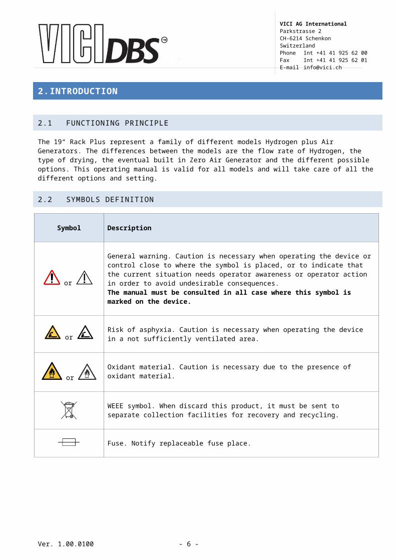
2. INTRODUCTION
2.1 FUNCTIONING PRINCIPLE
The 19“ Rack Plus represent a family of different models Hydrogen plus Air Generators. The differences between the models are the flow rate of Hydrogen, the type of drying, the eventual built in Zero Air Generator and the different possible options. This operating manual is valid for all models and will take care of all the different options and setting.
2.2 SYMBOLS DEFINITION
Symbol Description
or
General warning. Caution is necessary when operating the device or control close to where the symbol is placed, or to indicate that the current situation needs operator awareness or operator action in order to avoid undesirable consequences.The manual must be consulted in all case where this symbol is marked on the device.
or Risk of asphyxia. Caution is necessary when operating the device in a not sufficiently ventilated area.
or Oxidant material. Caution is necessary due to the presence of oxidant material.
WEEE symbol. When discard this product, it must be sent to separate collection facilities for recovery and recycling.
Fuse. Notify replaceable fuse place.
Ver. 1.00.0100 - 5 -
VICI AG InternationalParkstrasse 2CH-6214 SchenkonSwitzerlandPhone Int +41 41 925 62 00Fax Int +41 41 925 62 01E-mail [email protected]
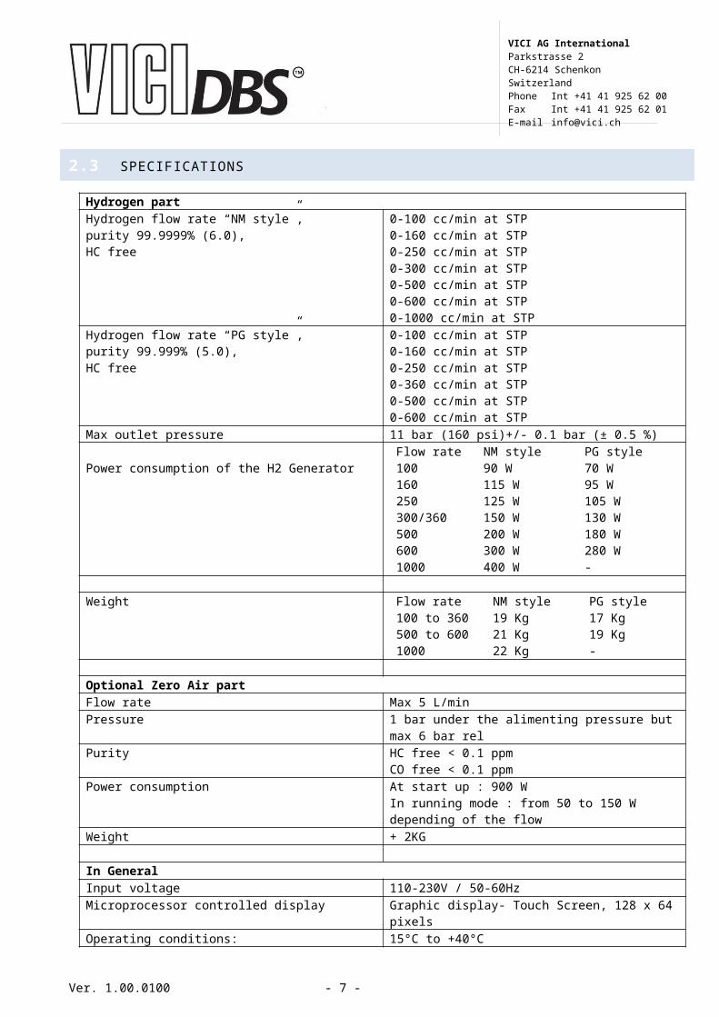
2.3 SPECIFICATIONS
Hydrogen partHydrogen flow rate “NM style”,purity 99.9999% (6.0),HC free
0-100 cc/min at STP0-160 cc/min at STP0-250 cc/min at STP0-300 cc/min at STP0-500 cc/min at STP0-600 cc/min at STP0-1000 cc/min at STP
Hydrogen flow rate “PG style”,purity 99.999% (5.0),HC free
0-100 cc/min at STP0-160 cc/min at STP0-250 cc/min at STP0-360 cc/min at STP0-500 cc/min at STP0-600 cc/min at STP
Max outlet pressure 11 bar (160 psi)+/- 0.1 bar (± 0.5 %)
Power consumption of the H2 GeneratorFlow rate NM style PG style100 90 W 70 W160 115 W 95 W250 125 W 105 W300/360 150 W 130 W500 200 W 180 W600 300 W 280 W1000 400 W -
Weight Flow rate NM style PG style100 to 360 19 Kg 17 Kg500 to 600 21 Kg 19 Kg1000 22 Kg -
Optional Zero Air partFlow rate Max 5 L/minPressure 1 bar under the alimenting pressure but max 6
bar relPurity HC free < 0.1 ppm
CO free < 0.1 ppmPower consumption At start up : 900 W
In running mode : from 50 to 150 W depending of the flow
Weight + 2KG
In GeneralInput voltage 110-230V / 50-60HzMicroprocessor controlled display Graphic display- Touch Screen, 128 x 64 pixelsOperating conditions:- Temperature- Relative humidity
15°C to +40°C0-80%, non condensing
Casing dimention 19 inch rack, 3U, 500mm deep
STP: Standard temperature and pressure (20°C, 1 bar)
Ver. 1.00.0100 - 6 -
VICI AG InternationalParkstrasse 2CH-6214 SchenkonSwitzerlandPhone Int +41 41 925 62 00Fax Int +41 41 925 62 01E-mail [email protected]
2.4 TRANSPORT AND STORAGE CONDITIONS
Temperature Minimum –10°C, maximum +45°CHumidity Inferior to 90%Rh, non condensingChocks and vibrations during transport Chocks < 1g; vibrations < 0.2g / 5HzInstrument’s position Horizontal
The above mentioned values are considered for an instrument transported in its original new packing.
Recommendations for the transport
When the instrument is shipped back to the factory for recalibration or repair, the gas divider + Nox should be packed in its original packing with the inlets and outlets protected against any accidental penetration of dust or particles of the package.
2.5 FUNCTIONING CONDITIONS
Operating temperature Minimum +15°C, maximum +40°CHumidity Inferior to 80%Rh, non condensingAtmospheric pressure From 850 to 1150 hPExternal vibrations Inferior to 0.05g / 25HzInstrument’s position Horizontal
2.6 PACKAGING LIST
List of items included in the shipment.
Quantity Description
1 Hydrogen generator1 External tank1 Filter for inlet Air (only if the option Air is installed)1 Instruction manual CD1 Deionizer bag1 Water drain with flexible tubing1 Power cable
Ver. 1.00.0100 - 7 -
VICI AG InternationalParkstrasse 2CH-6214 SchenkonSwitzerlandPhone Int +41 41 925 62 00Fax Int +41 41 925 62 01E-mail [email protected]

3. SAFETY
Indoor use only
Always unplug the unit from the mains power supply before accessing the internal components for replacement.
Depressurize completely the instrument and close the O2 Vent BEFORE handle it.
Depressurize completely the instrument, close the O2 Vent , and empty from the water BEFORE ship it.
4. WARNING
Never operate the unit in below-zero temperatures. This will cause irreversible damage to the electrolysis cell.
Only use pure (deionised) water (see “Filling the water tank”)
Only operate the unit in a room with sufficient ventilation (see “Placing the unit”).
Only the parts described in the “Spare parts list” can be replaced by the user.
Ver. 1.00.0100 - 8 -
VICI AG InternationalParkstrasse 2CH-6214 SchenkonSwitzerlandPhone Int +41 41 925 62 00Fax Int +41 41 925 62 01E-mail [email protected]

5. SPECIFICATIONS
5.1 THE MOST COMMON OPTION
5.1.1. Remote Connections (I/O Board)
This option request the I/O board optionThe hydrogen generators are fitted with an optional remote control feature, which allows the user to check the status of the machine from a remote position, and to start/stop the production of hydrogen. The contacts used in the remote control are potentially free relay contacts. The contacts can be configured via software as normally-open or normally-closed (see the Configuration section). The maximum voltage and current ratings for the contacts are 1A / 48V. The pin configuration of the remote connector is shown in the table below.
Remote connector pin configuration
Pin Description1+2 Start (12-30 VDC polarity not important)3+4 Standby5+6 Reaching external pressure09+10 Low water level11+12 Bad water13+14 Change water
Ver. 1.00.0100 - 9 -
VICI AG InternationalParkstrasse 2CH-6214 SchenkonSwitzerlandPhone Int +41 41 925 62 00Fax Int +41 41 925 62 01E-mail [email protected]

5.1.2. Cascading
This option required the I/O board option
The RS-485 interface allows up to 10 generators to be operated in parallel mode. The generators are connected with an external non return valve to a gas line. The pressure must be controlled with an external pressure regulator. The outlet pressure is fixed to 10.3 bars. This mode allows up to 10 generators in a cascading group.How does cascading work:The communication of the generators is done via the RS-485 Interface. For a correct communication each generator need a unique ID number. Each generator must know how many generators are connected in the cascading group. As soon as the generators are powered up, one generator becomes the master, and controls the others (slaves). If there is a problem with the master, one of the slave generators will become the master. Every generator can be forced to be the master, by entering into the menu you will see the function “force to master” , just select this function and acknowledge.When a generator is the master, you can see the letter “M” in the menu button, while the slaves show the letter “S”.
The cascading function will only work properly if the gas outlets on all the generators are connected to the same gas line.
Ver. 1.00.0100 - 10 -
VICI AG InternationalParkstrasse 2CH-6214 SchenkonSwitzerlandPhone Int +41 41 925 62 00Fax Int +41 41 925 62 01E-mail [email protected]

6. THE UNIT
6.1 FRONT VIEW
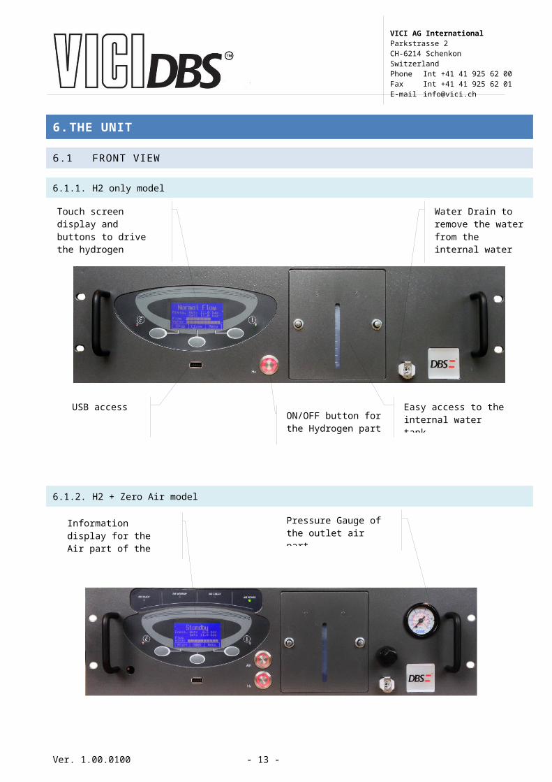
6.1.1. H2 only model
6.1.2. H2 + Zero Air model
6.1.3. Zero Air only model
Ver. 1.00.0100 - 11 -
Touch screen display and buttons to drive the hydrogen generator
Water Drain to remove the water from the internal water tank
USB accessON/OFF button for the Hydrogen part
Easy access to the internal water tank
Information display for the Air part of the Generator
Outlet pressure regulator of the air
Pressure Gauge of the outlet air part
ON/OFF button for the Air part
VICI AG InternationalParkstrasse 2CH-6214 SchenkonSwitzerlandPhone Int +41 41 925 62 00Fax Int +41 41 925 62 01E-mail [email protected]

6.2 BACK VIEW
6.2.1. H2 only model
Ver. 1.00.0100 - 12 -
Information display for the Air part of the Generator
AIR ON/OFF buttonOutlet pressure regulator of the air
Pressure Gauge of the outlet air part
Hydrogen outlet
110/230 V inlet
Set the correct fuses
Outlet H2 relief valve
Remove plug before use
I/O board option
Inlet external water tank
Outlet Vent O2
Remove plug before use
VICI AG InternationalParkstrasse 2CH-6214 SchenkonSwitzerlandPhone Int +41 41 925 62 00Fax Int +41 41 925 62 01E-mail [email protected]
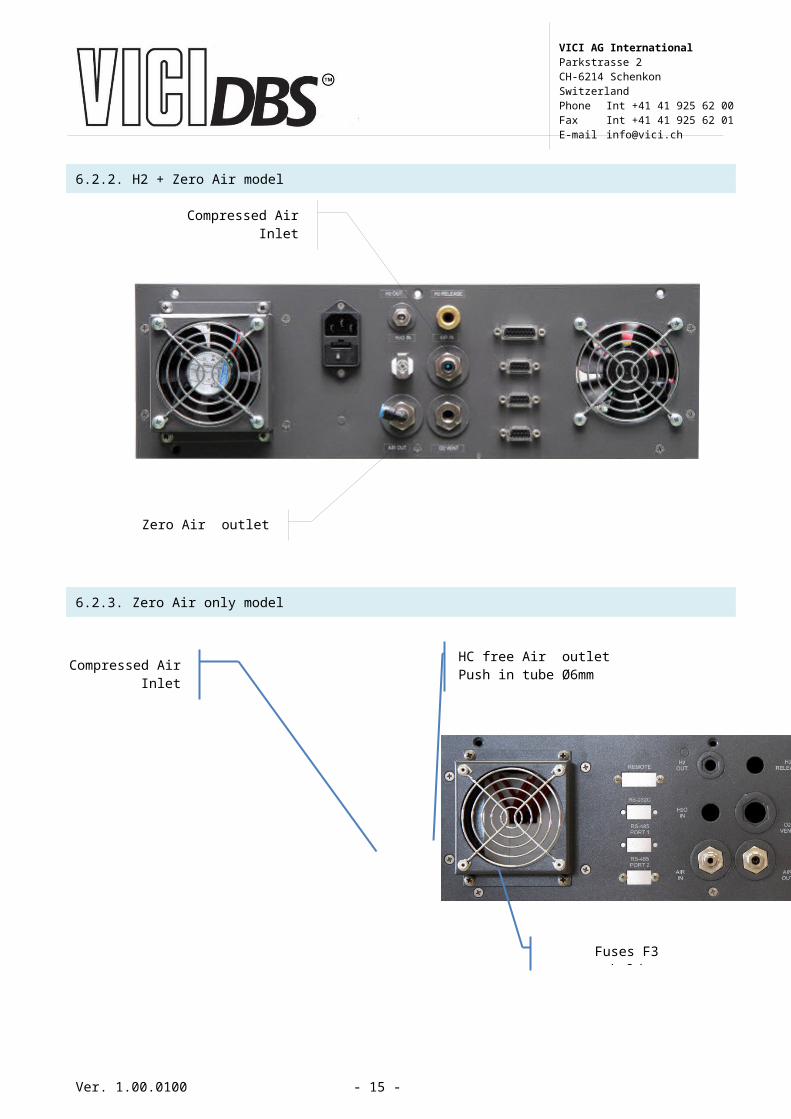
6.2.2. H2 + Zero Air model
6.2.3. Zero Air only model
Ver. 1.00.0100 - 13 -
Compressed AirInlet
Zero Air outlet
Compressed Air Inlet
Push in tube Ø6mm
HC free Air outletPush in tube Ø6mm
Fuses F3 holder
VICI AG InternationalParkstrasse 2CH-6214 SchenkonSwitzerlandPhone Int +41 41 925 62 00Fax Int +41 41 925 62 01E-mail [email protected]

6.3 TOP VIEW
6.3.1. H2 only model (PG Style)
Ver. 1.00.0100 - 14 -
VICI AG InternationalParkstrasse 2CH-6214 SchenkonSwitzerlandPhone Int +41 41 925 62 00Fax Int +41 41 925 62 01E-mail [email protected]
6.3.2. H2 + Zero Air model (NM Style)
6.4 DIMENSIONS
Ver. 1.00.0100 - 15 -
VICI AG InternationalParkstrasse 2CH-6214 SchenkonSwitzerlandPhone Int +41 41 925 62 00Fax Int +41 41 925 62 01E-mail [email protected]

6.5 SCHEMES
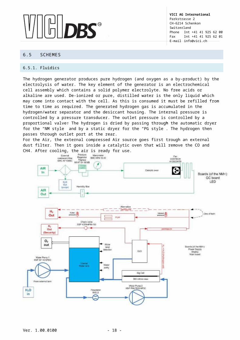
6.5.1. Fluidics
The hydrogen generator produces pure hydrogen (and oxygen as a by-product) by the electrolysis of water. The key element of the generator is an electrochemical cell assembly which contains a solid polymer electrolyte. No free acids or alkaline are used. De-ionized or pure, distilled water is the only liquid which may come into contact with the cell. As this is consumed it must be refilled from time to time as required. The generated hydrogen gas is accumulated in the hydrogen/water separator and the desiccant housing. The internal pressure is controlled by a pressure transducer. The outlet pressure is controlled by a proportional valve. The hydrogen is dried by passing through the automatic dryer for the “NM style” and by a static dryer for the “PG style”. The hydrogen then passes through outlet port at the rear.For the Air, the external compressed Air source goes first trough an external dust filter. Then it goes inside a catalytic oven that will remove the CO and CH4. After cooling, the air is ready for use.
Ver. 1.00.0100 - 16 -
VICI AG InternationalParkstrasse 2CH-6214 SchenkonSwitzerlandPhone Int +41 41 925 62 00Fax Int +41 41 925 62 01E-mail [email protected]

6.5.2. Electronics
Ver. 1.00.0100 - 17 -
VICI AG InternationalParkstrasse 2CH-6214 SchenkonSwitzerlandPhone Int +41 41 925 62 00Fax Int +41 41 925 62 01E-mail [email protected]
7. INSTALLATION AND INITIAL START-UP
7.1 GENERAL
7.1.1. Receiving the generator
All units have been carefully inspected before transport. Visual checks for damage and functional tests should be performed upon receipt. Any damage must be immediately noted and reported. The generator must only be returned according to the shipping instructions provided.
Conserve the ORIGINAL packaging is case of return.
7.1.2. Placing the generator
The hydrogen generator must be placed on a flat, level, vibration-free, shock-free surface. Do not place the generator over a source of heat, as this may cause the device to overheat. The unit should not be in contact with any other objects on any side, and the air inlet must not be blocked. Leave at least 30 cm of free space at the rear for ventilation. Do not operate the generator in a sealed or unventilated room, or in close proximity to open flame or other sources of ignition. Do not operate the generator at below freezing temperatures. Operation is guaranteed at operating temperatures between +15 and +40°C.
Normal precautions for any hydrogen supply should be taken when using the generator. DO NOT use in sealed or unventilated rooms.
DO NOT use in close proximity of open flames or other sources of ignition.
Ver. 1.00.0100 - 18 -
VICI AG InternationalParkstrasse 2CH-6214 SchenkonSwitzerlandPhone Int +41 41 925 62 00Fax Int +41 41 925 62 01E-mail [email protected]

7.2 VOLTAGE SELECTIONS
Check the setting of the voltage selector on the rear of the unit. The set voltage is indicated by the little window. To change the voltage, proceed as follows:
Using a small screwdriver, remove the voltage selector insert. Replace the voltage selector insert so that the white arrow points to the correct voltage.
Use only 240 VAC or 120 VAC setting and use the correct fuses!
7.3
GAS CONNECTIONS
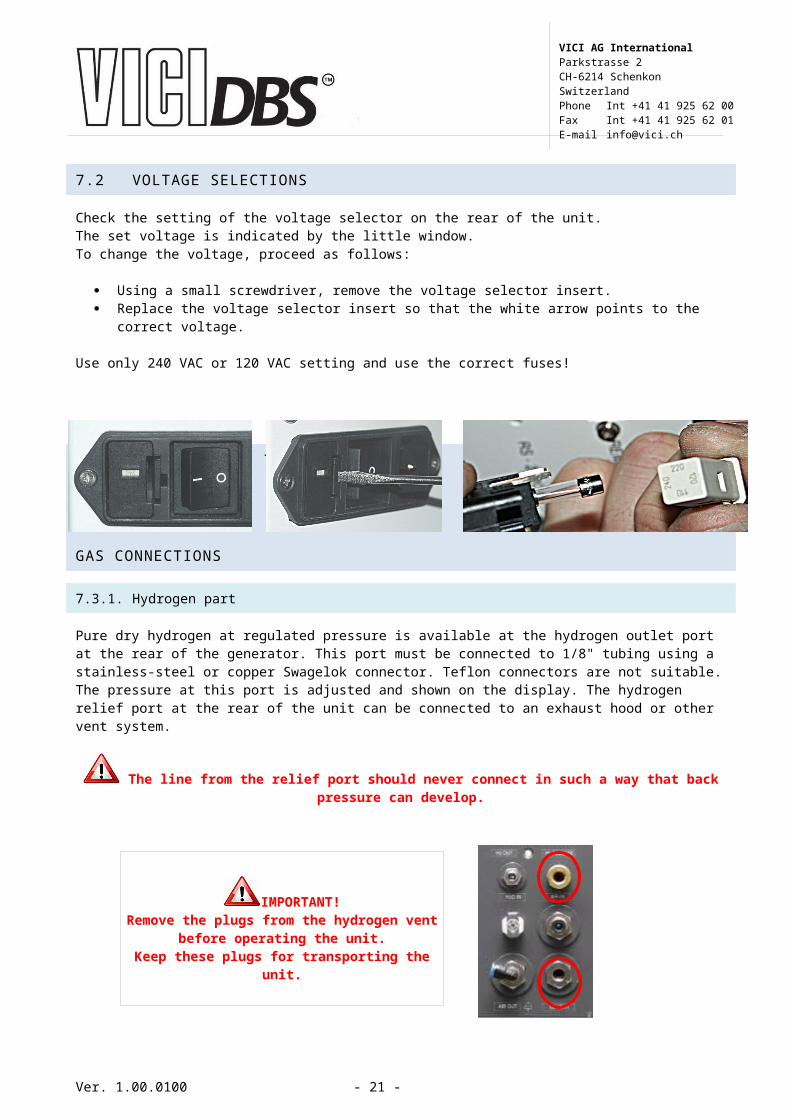
7.3.1. Hydrogen part
Pure dry hydrogen at regulated pressure is available at the hydrogen outlet port at the rear of the generator. This port must be connected to 1/8" tubing using a stainless-steel or copper Swagelok connector. Teflon connectors are not suitable. The pressure at this port is adjusted and shown on the display. The hydrogen relief port at the rear of the unit can be connected to an exhaust hood or other vent system.
The line from the relief port should never connect in such a way that back pressure can develop.
Ver. 1.00.0100 - 19 -
IMPORTANT!Remove the plugs from the hydrogen
vent before operating the unit.Keep these plugs for transporting the
unit.
VICI AG InternationalParkstrasse 2CH-6214 SchenkonSwitzerlandPhone Int +41 41 925 62 00Fax Int +41 41 925 62 01E-mail [email protected]

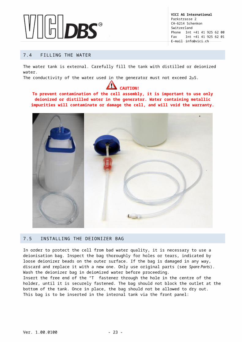
7.4 FILLING THE WATER
The water tank is external. Carefully fill the tank with distilled or deionized water.The conductivity of the water used in the generator must not exceed 2S.
CAUTION!To prevent contamination of the cell assembly, it is important to use only deionized
or distilled water in the generator. Water containing metallic impurities will contaminate or damage the cell, and will void the warranty.
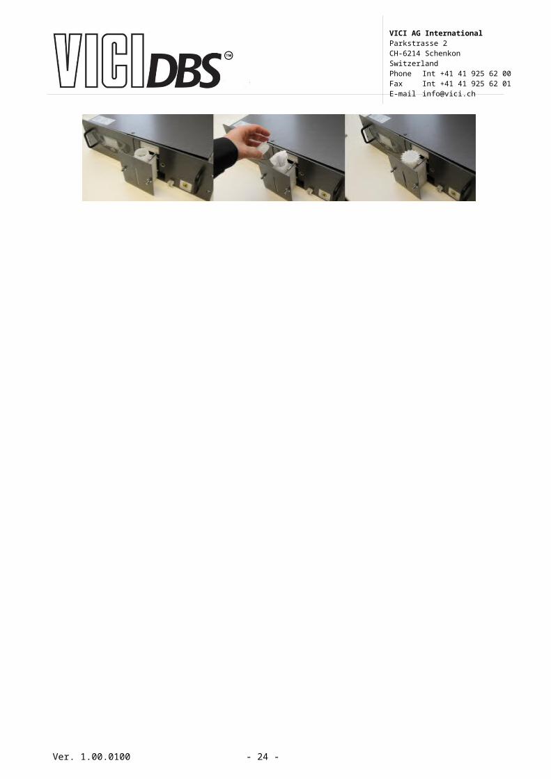
7.5 INSTALLING THE DEIONIZER BAG
In order to protect the cell from bad water quality, it is necessary to use a deionisation bag. Inspect the bag thoroughly for holes or tears, indicated by loose deionizer beads on the outer surface. If the bag is damaged in any way, discard and replace it with a new one. Only use original parts (see Spare Parts). Wash the deionizer bag in deionized water before proceeding.Insert the free end of the “T” fastener through the hole in the centre of the holder, until it is securely fastened. The bag should not block the outlet at the bottom of the tank. Once in place, the bag should not be allowed to dry out.This bag is to be inserted in the internal tank via the front panel:
Ver. 1.00.0100 - 20 -
VICI AG InternationalParkstrasse 2CH-6214 SchenkonSwitzerlandPhone Int +41 41 925 62 00Fax Int +41 41 925 62 01E-mail [email protected]
7.6 STARTING THE HYDROGEN GENERATOR
Once the ON/OFF button is pressed the Hydrogen generator will start to work.
Following screen will appear.Press “Menu” to select the correct sub menu (to set the pressure)
Press “Select” to select to go inside the “pressure adjust” menu
Use the arrows “up” and “down” to select the desired outlet pressure.Once done, press “Excit”
Press “start”.
The generator will first build the internal pressure. You have to wait until it reach 100% before going on
At this point, make sure that you have connected the outlet Hydrogen to your GC or application. At least make sure you have a restriction and that the outlet is not fully open.
Once done, press “Open”. The hydrogen will go through the outlet and the pressure will rise until it reaches the selected pressure.
Ver. 1.00.0100 - 21 -
VICI AG InternationalParkstrasse 2CH-6214 SchenkonSwitzerlandPhone Int +41 41 925 62 00Fax Int +41 41 925 62 01E-mail [email protected]

Once reached, the generator will show “Normal flow”
7.7 STARTING THE ZERO AIR GENERATOR
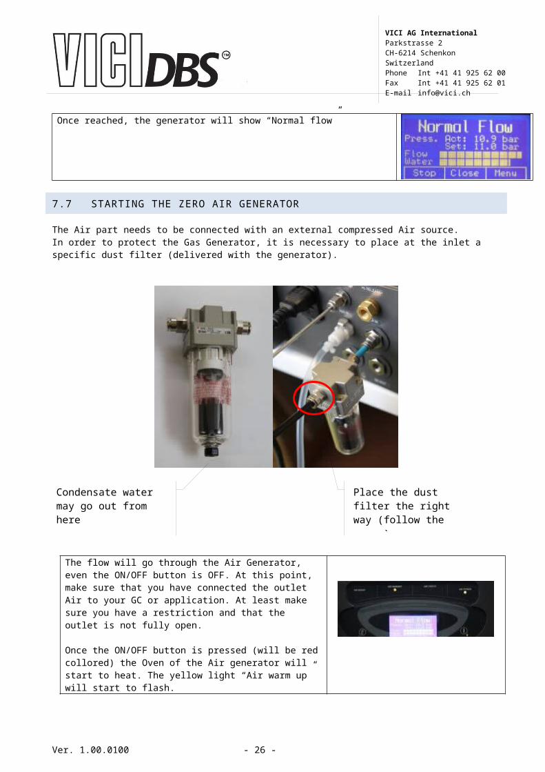
The Air part needs to be connected with an external compressed Air source. In order to protect the Gas Generator, it is necessary to place at the inlet a specific dust filter (delivered with the generator).
The flow will go through the Air Generator, even the ON/OFF button is OFF. At this point, make sure that you have connected the outlet Air to your GC or application. At least make sure you have a restriction and that the outlet is not fully open.
Once the ON/OFF button is pressed (will be red collored) the Oven of the Air generator will start to heat. The yellow light “Air warm up” will start to flash.
Once the temperature is reached, the green “Air ready” led will light. The instrument is ready to work
Ver. 1.00.0100 - 22 -
Condensate water may go out from here
Place the dust filter the right way (follow the arrow)
VICI AG InternationalParkstrasse 2CH-6214 SchenkonSwitzerlandPhone Int +41 41 925 62 00Fax Int +41 41 925 62 01E-mail [email protected]
8. OPERATION
8.1 HYDROGEN PART DISPLAY TREE
The operating status of the unit is shown on the main screen on the graphic display.The main screen has three options at the bottom, corresponding to the three buttons on the unit and the part of touch screen, which are used to run the various functions and access the configuration and diagnostics of the unit, following the tree structure shown in the figure below.
Ver. 1.00.0100 - 23 -
VICI AG InternationalParkstrasse 2CH-6214 SchenkonSwitzerlandPhone Int +41 41 925 62 00Fax Int +41 41 925 62 01E-mail [email protected]
8.2 CONFIGURE PARAMETERS
Item Description Options / Range DefaultSet Clock Adjusting the internal Clock - -Low Press Error* Percentage of total pressure that has to be
beat for activating the low pressure.0-100% 30%
Pressure rise Sets how fast the pressure has to increase. If the pressure increases at a slower rate, a low pressure alarm is activated.
0.01 – 4.2 bar/min0.2 - 60 psi/min
0.0914
Pressure drop delay
Sets a delay in seconds to ignore a pressure drop (override low pressure alarm)
2 - 10 min 2
Auto start Sets whether the unit automatically starts production when power is switched on.
YES / NO NO
Beeper Sets whether the audible signal is activated in the event of an alarm.
ON / OFF ON
Cascading mode Sets the cascading mode. (see cascading for more details)
None/ Normal / Ext. P control
None
N Gen H2 in cascading
Sets the number of generators in theCascading chain
1-10 1
ID number Sets the ID number 1-10 1Remote start/stop mode
Configures the remote start/stop function Start/stop, Start only, Direct control
start/stop
Remote relay mode
Configures the remote relay contacts. Normally open (NO)Normally closed (NC)
NC
Autorefill If set to ON, the pre-level water alarm is used to trigger an external pump or valve to refill the water tank
ON / OFF OFF
Pre alarms in list If set to Yes, the pre alarms are also shown in the alarm log.
YES / NO NO
Pressure units Sets the desired unit of measure for the pressure
bar / psi / kPa bar
Temp. units Sets the desired unit of measure for the temperature
°C and °F °C
Volume units Sets the desired unit of measure for the volume
scm (standard cubic meters)scf (standard cubic feet)
scm
Lock Keyboard If set to Yes, the keyboard will be locked automatically after the generator is in the main window for more than 20s. To unlock the keyboard, press the unlock button and hold for 5s.
YES / NO NO
Set default values
Sets all configuration parameters todefault
*BE CAREFUL: With a 100% set, the generator will never go in External Pressure Alarm.
Ver. 1.00.0100 - 24 -
VICI AG InternationalParkstrasse 2CH-6214 SchenkonSwitzerlandPhone Int +41 41 925 62 00Fax Int +41 41 925 62 01E-mail [email protected]

8.3 DIAGNOSTIC DISPLAY
Item DescriptionProduction Tot. Total production of hydrogenOperating time (h) Total number of hours the unit operationWat. quality (S) Actual water conductivityInt. Press.: Actual internal pressure of the unitCell voltage (V) Actual cell voltageCell current (A) Actual cell currentPS. temp. Actual temperature of the power supplyCell voltage peak (V) The maximum cell voltage in the life of the cellPS. temp. peak The maximum temperature of the PCB reachedPump Flow (l/min) Actual flow of water
8.4 SPECIAL FUNCTIONS
Item DescriptionDryer status Shows the temperatures of the drying columns and the
position of the cycleSystem test This offers several test functions see belowInternal leak test The outlet valve is closed, the pressure is set to the max.,
when the pressure reaches the max., production is stopped and the pressure drop is measured over 2 minutes. The pressure drop should below0.7 bars or 10 PSIImportant: The leak test will only work if the generator is in standby mode.
External leak test Works similar to the leak internal except the outlet valve is open and the test pressure is equal to the set pressureThis function can be used to test the external gas linesImportant: The leak external will only work if the generator is in standby mode.
Flow test This functions sets the outlet valve to provide a certain flowAdjustable from 0 to 100% of maximum flow.Important: this function will only work if the generator is in standby mode. It will take approx. 2 minutes to get a stable flow!
Rinse flow test This test checks the amount of gas flow, for the dryer regeneration
Complete system test Combination of all tests aboveHardware options not available for user (password protected)
Ver. 1.00.0100 - 25 -
VICI AG InternationalParkstrasse 2CH-6214 SchenkonSwitzerlandPhone Int +41 41 925 62 00Fax Int +41 41 925 62 01E-mail [email protected]
9. MAINTENANCE
With proper care and maintenance, your hydrogen generator should provide you with years of trouble-free operation. There are no adjustments to be made to the generator. The only routine service operations are those described below.
Nonetheless, the generator should be inspected approximately every 2 years. Contact your supplier.
9.1 ROUTINE MAINTENANCE
The following section describes the maintenance operations required for the correct operation of the hydrogen generator.The routine maintenance consists:
Fill the external water tank Replace the deionization bag every 6 monthsReplace the water filter (inside the external tank) every 6 monthsReplace the filtering element of the dust filter every 6 months (only if Air is installed)
IMPORTANT!The manufacturer reserves the right to change or modify its products without prior
notice.
Ver. 1.00.0100 - 26 -
VICI AG InternationalParkstrasse 2CH-6214 SchenkonSwitzerlandPhone Int +41 41 925 62 00Fax Int +41 41 925 62 01E-mail [email protected]


![Book, The Electric Generators Handbook Synchronous Generators[1]](https://img.pdfslide.us/doc/110x75/552a938b55034689428b46a1/book-the-electric-generators-handbook-synchronous-generators1.jpg)