Embed Size (px)
Citation preview

In-line solid state prediction during pharmaceutical
hot-melt extrusion in a 12 mm twin screw extruder
using Raman spectroscopy
Lien Saerensa*, Dima Ghanamb, Cedric Raemdonckc, Kjell Francoisc, Jürgen Manzc, Rainer Krügerd,
Susan Krügerd, Chris Vervaete, Jean Paul Remone, Thomas De Beera
aLaboratory of Pharmaceutical Process Analytical Technology, Ghent University, Harelbekestraat 72, 9000
Ghent, Belgium
bBrabender® Pharma, Kulturstraße 51-55, 47055 Duisburg, Germany
cSiemens NV, Marie Curie Square 30, 1070 Brussels, Belgium
dJosteit & Krüger Consulting, Bahnhofstr. 315/Hörnemannshof, D-47447 Moers, Germany
eLaboratory of Pharmaceutical Technology, Ghent University, Harelbekestraat 72, 9000 Ghent, Belgium
*Corresponding author:
Lien Saerens
Laboratory of Pharmaceutical Process Analytical Technology
Harelbekestraat 72
9000 Ghent
Belgium
Phone: +32 9 264 8355
Email: [email protected]
KEYWORDS. Hot-melt extrusion, Continuous production, in-line Raman spectroscopy, solid state
prediction, PAT
1

Abbreviations
API active pharmaceutical ingredient
CEL celecoxib
DCrit critical distance
DModX distance to model X
DSC differential scanning calorimetry
HME hot-melt extrusion
PAT process analytical technology
PC principal component
PCA principal component analysis
SIMCA soft independent modelling of class analogy
Tg glass transition temperature
Tm melt temperature
XRD x-ray diffraction
2

Abstract
The aim of this research was to use Raman spectroscopy for the in-line monitoring of the solid state
of materials during pharmaceutical hot-melt extrusion in the die head of a 12 mm (development
scale) twin-screw extruder during formulation development.
A full factorial (mixed) design was generated to determine the influence of variations in
concentration of Celecoxib (CEL) in Eudragit® E PO, three different screw configurations and varying
barrel temperature profiles on the solid state, ‘melt temperature’ and die pressure of continuously
produced extrudates in real-time. Off-line XRD and DSC analysis were used to evaluate the suitability
of Raman spectroscopy for solid state predictions. First, principal component analysis (PCA) was
performed on all in-line collected Raman spectra from the experimental design. The resulting PC1
versus PC2 scores plot showed clustering according to solid state of the extrudates, and two classes,
one class where crystalline CEL is still present and a second class where no crystalline CEL was
detected, were found. Then, a soft independent modelling of class analogy (SIMCA) model was
developed, by modelling these two classes separately by disjoint PCA models. These two separate
PCA models were then used for the classification of new produced extrudates and allowed distinction
between glassy solid solutions of CEL and crystalline dispersions of CEL. All extrudates were classified
similarly by Raman spectroscopy, XRD and DSC measurements, with exception of the extrudates with
a 30% CEL concentration extruded at 130°C . The Raman spectra of these experiments showed bands
which were sharper than the amorphous spectra, but broader than the crystalline spectra, indicating
the presence of CEL that has dissolved into the matrix and CEL in its crystalline state. XRD and DSC
measurements did not detect this. Modifications in the screw configuration did not affect the solid
state and did not have an effect on the solid state prediction of new produced extrudates.
3

Secondly, the influence of variations in die pressure on the Raman spectra was examined. The
applied drug concentration, processing temperature and feeder performance influence the die
pressure, which is reflected in the Raman spectra as a change in spectral intensity. When applying
PCA on the raw spectra from the experimental design, the first principal component describes the
influence of die pressure on the spectra, which was seen as a decrease in Raman intensity of the
whole spectrum when the pressure in the sample increased. Clustering according to processing
temperature was found, although the temperature in the die remained constant, indicating that a
difference in viscosity, resulting in a changed die pressure, was detected. When the feeder was
stopped, the score values of the first principal component almost simultaneously decreased, and only
stabilized once the die pressure became stable. Since Raman spectra collected in the extrusion die
are influenced by changes in die pressure, disturbances upstream of the extrusion process can be
observed and identified in the Raman measurements.
4

Introduction
The high throughput screening of potential therapeutic agents has increased the amount of poorly
soluble drug candidates. In the Biopharmaceutical Classification System (BCS), many active
pharmaceutical ingredients (APIs) such as Celecoxib (CEL) have been categorized as Class II, implying
that they have a high permeability, but a low aqueous solubility. The bioavailability of this type of
compounds is limited by their dissolution rate. The low water solubility of these compounds makes it
challenging to formulate them for oral delivery. Several manners of improving the dissolution of the
drug have been proposed [1], but the preferred option to enhance the solubility and therefore the
bioavailability of the drug is through formulation approaches. Presenting the compound as a solid
dispersion will reduce the particle size of the API, improve the wettability, increase the porosity, and
allow the formulation of drugs in their amorphous state [2]. The current method of choice for the
manufacturing of solid dispersions is hot-melt extrusion (HME) [1]. Melt extrusion has several
advantages over solvent based methods for forming glass solid solutions (solid dispersions where the
API is completely dissolved in an amorphous carrier). When applying solvent evaporation methods,
the first challenge is to find a solvent in which both API and carrier are soluble [3]. Other
disadvantages of solvent methods include difficulties of removing the residual (organic) solvent,
toxicity issues due to residual solvent, the requirement of a secondary drying step and possible
ecological problems [1, 2, 4]. Using hot-melt extrusion to produce solid dispersions requires high
processing temperatures, but avoids the need for solvents. Furthermore, HME is a one step
continuous process with decreased ecological implications. It has been shown that glassy solid
solutions of CEL can be produced via hot-melt extrusion using several polymer carriers, each
increasing the dissolution rate of the drug [5, 6].
Process analytical tools such as Raman spectroscopy can provide in-line and real-time information
about critical process and formulation parameters. Raman spectroscopy has been used off-line in
5

previous studies for the physical characterization of solid dispersions. It can be applied to determine
the type of solid dispersion (solid solution, glass suspension, etc.), the solid state of the API and
polymers and the occurring molecular interactions between polymer and drug [6-9]. Custom made
fibre optic probes connected to the spectrometer can be implemented into the HME equipment [10].
In-die monitoring of solid state and molecular interactions during a pharmaceutical hot-melt
extrusion process, has already been demonstrated using Raman spectroscopy [9] and NIR
spectroscopy [11]. The aim of this work is to demonstrate the application of Raman spectroscopy as a
PAT tool during formulation development and to determine the influence of varying process settings
on the material properties. Therefore, the solid state properties of the melt were determined in-line
during hot-melt extrusion on a 12 mm development scale twin screw extruder with low material
need, avoiding the dissipation of materials and making off-line analysis redundant.
6

Materials and methods
1. Materials
Celecoxib (CEL) (Selectchemie, Zürich, Switzerland) was selected as a model drug. CEL is an example
of a poorly soluble (BCS Class II) drug with a water solubility of 3-7 mg/L and a melting temperature
(Tm) of 163°C. The polymer Eudragit® E PO (Evonik®, Weiterstadt, Germany) was used to form the
matrix system. It is a cationic copolymer based on dimethylaminoethyl methacrylate, butyl
methacrylate, and methyl methacrylate. Eudragit® E PO is an amorphous polymer, used to create the
matrix in which CEL is dissolved.
The solubility parameters of both components were calculated with SPWin, version 2.11 [12], to give
an indication of miscibility of polymer and drug. The calculated values were 26.7 MPa½ and 19.7
MPa½ for CEL and Eudragit® E PO respectively. For components with a difference in solubility
parameters (t) smaller than 2.0 MPa1/2, melt extrusion is expected to result in a glass solution,
whereas components with t > 10 MPa½ are likely to be immiscible [13]. When t lays between 5
MPa1/2 and 10 MPa1/2, prediction of glass solution formation requires further investigation with
thermal analysis. As the difference in total solubility parameters is 7.0 MPa ½, further DSC
measurements were performed to assess the solubility of CEL in Eudragit® E PO.
Physical mixtures of both components were prepared with a Turbula® T2F mixer (Willy A. Bachofen
GmbH, Muttenz, Switzerland). The concentration of CEL was varied between 30% and 50% (w/w) in
Eudragit® E PO throughout the experiments (Table 1).
7
2. Hot-melt extrusion
Hot-melt extrusion was performed with a development scale co-rotating twin-screw extruder with a
screw diameter of 12mm (PTSE 12/36, Brabender® Pharma, Duisburg, Germany). The extruder was
equipped with a loss in weight feeder (Brabender® Technologie, Duisburg, Germany), which was used
in its gravimetric feeding mode and supplied the physical mixtures with a throughput of 1.5 g/min.
Three different screw configurations were applied during experiments (Table 1): the first
configuration included 2 consecutive forward kneading blocks (FF), a second configuration contained
a forward kneading block followed by a backward kneading block (FB), and the third screw setup
comprised 2x2 consecutive forward kneading blocks (2F) (Fig. 1). Each of the kneading blocks has a
length of 1.5D, containing 5 kneading elements with an offset angle of 45°. The FF configuration will
induce the lowest amount of shear on the mixture and will result in the shortest residence time.
When the shear forces on the mixture increase, and the time of exposure to a high temperature
becomes longer, the formation of a glass solution will be facilitated. Shear forces and residence time
values will increase when two more forward kneading blocks are added to the design, or when a
forward kneading block is replaced by a backward kneading element [14, 15]. The impact of these
design alterations is expected to be more distinct at lower processing temperatures than at the
higher barrel temperatures. The processing temperature was varied from 130°C to 150°C throughout
the experiments, and the die temperature was kept constant (110°C) for each experiment to
guarantee a solid end product (Table 1). Logging of the extrusion settings (throughput, screw speed,
barrel and die temperature) and parameters (actual barrel, die and product temperature, actual
throughput, actual screw speed, die pressure, motor load) was performed with the WinExtXT®
software (Brabender® Pharma, Duisburg, Germany). Extrudate samples were collected during the
experiments and stored at room temperature.
8
3. Raman spectroscopy
Both in-line and off-line Raman spectra were collected with a Raman Rxn1 spectrometer (Kaiser
Optical Systems, Ann Arbor, MI, USA). For in-line measurements, a fibre-optic Raman Dynisco probe
was built into die head (Fig. 2), to monitor the solid state of the extrudate before it is forced through
the die. The laser wavelength was the 785 nm line from a 785 nm Invictus NIR diode laser. All in-line
collected spectra were recorded with a resolution of 4 cm -1 and an exposure time of one second,
using a laser power of 400 mW. Spectra were collected every 20 seconds. The analyzed spectral
region was 100 – 1800 cm-1, since this region contains all envisaged drug and polymer information.
Prior to data analysis, SNV pre-processing was applied on the in-line collected spectra to eliminate
the additive baseline offset variations and multiplicative scaling effects in the spectra, induced by
pressure variations at the measurement point.
After storage of the samples collected during extrusion at room temperature for one year, off-line
Raman spectra of the extrudates were collected to verify the stability of the end products. These
spectra were recorded with a resolution of 4 cm-1 and an exposure time of five seconds, using a laser
power of 400 mW.
4. Data collection, alignment and analysis
An experimental design (Table 1) was created using the MODDE software (version 9.1.0.0, Umetrics,
Umeå, Sweden) to study the influence of the above described factors (drug load, screw configuration
and processing temperature) on extrusion. The applied design was a full factorial (mixed) screening
design with two quantitative factors, CEL concentration and processing temperature, and screw
configuration as a qualitative factor with three levels (FF, FB and 2F, Fig. 1). The monitored responses
in the design are the melt temperature as measured by the temperature probe in the die head, die
9
pressure and the solid state of the extrudates, which was monitored with Raman spectroscopy. Data
collection during each design experiment (Raman spectral data + logged data) and data alignment
were automated using the SIPAT software (Siemens NV, Brussels, Belgium) and SIMCA Q (Umetrics,
Umeå, Sweden). Raman spectral data analysis was performed using SIMCA P+ (version 12.0.1.0,
Umetrics, Umeå, Sweden).
The analysed spectral region was the region from 0 to 1800 cm -1. Since the formulation coloured
slightly yellow (due to the use of Eudragit® E PO) during extrusion, the background signal of all
Raman spectra gained intensity. Coloured substances will absorb laser beam energy, and generate
fluorescence which contaminates the Raman spectrum. However, the peaks of CEL were still
detectable in the in-line collected spectra. Soft independent modelling of class analogy (SIMCA) was
used to distinguish between extrudates containing crystalline CEL, and extrudates where a glassy
solid solution was formed, where CEL is molecularly dissolved into the polymer matrix. Therefore,
principal component analysis (PCA) was in first instance performed on all spectra collected during the
design experiments (Table 1), hence providing a general overview of the data and giving an indication
of present class separation (i.e., glassy solid solution versus crystalline suspension), trends and
outliers [16]. Subsequent to this initial overview, each class of observations determined from this
PCA was modelled separately by disjoint PCA models. These two separate PCA models were then
used to predict a likely class membership for new observations. Based on the residual variation of
each class, the distance to the model (DModX) for each (new) observation can be calculated [14].
DModX values are calculated as (1):
DModX=√ ∑ e ik2
(K−A )(1)
10

Where eik are the sum-squared residuals after projection of the observation on the PCA model of a
certain class, A is the number of principal components retained to model this class and K is the num-
ber of variables. A critical distance (Dcrit) to the model is calculated (from the F-distributed values of
the residual standard deviation of each observation divided by the pooled residual standard devia-
tion of the model) and is set at the 0.05 probability level. When the probability of belonging to the
model is higher than 95%, the observation is considered as a member of that particular class. Obser -
vations that do not fit any class, i.e. observations found outside Dcrit are considered as either outliers
or members of a new, unseen class. In a Coomans’ plot, DModX values for two classes are plotted
against each other in a scatter plot. By plotting the class membership limits (Dcrit) as well, four areas
of diagnostic interest are created. The upper left-hand and lower right-hand area is where observa-
tions belonging to one of both classes can be found. In the lower left-hand area of the plot, there is a
region where prediction set samples that fit both models are found, and in the upper right-hand area
the observations that do not conform with either of the models are found.
The ability of a class model to classify observations correctly cannot be realistically assessed if only
training set samples are considered. It is recommended that an independent prediction set of
observations that have not influenced the model calculations be employed. This will enable a more
realistic assessment of the classification performance of each model [14]. The classification model
developed for classification of new samples was implemented in the SIPAT software, and applied for
real-time data analysis and solid state predictions of new runs.
5. Differential scanning calorimetry
From each experiment (table 1), samples were collected after extrusion. Differential scanning calori-
metry was performed with a DSC Q 2000 (TA Instruments, Belgium). The thermograms were pro -
duced with the Thermal Advantage Release 5.1.2 software and analysed with TA Instruments Univer-
11

sal Analysis 2000 4.7A (TA Instruments, Belgium). Hermetically sealed aluminium hermetic pans (TA
Instruments, Belgium) were used to contain the samples. Measurements were carried out in a nitro-
gen atmosphere. The flow rate of dry nitrogen gas was 50 mL/min. Samples were subjected to three
cycles. First, the pans were heated with a heating rate of 10,0 °C/min from 0°C up to 200°C in the first
heating cycle. Then, a cooling cycle was started with a cooling rate of -10,0 °C/min to 0°C, followed
by a second and final heating cycle which was identical to the first. The results from the first heating
cycle reflect the influences of the hot-melt extrusion processing on the mixture, whereas the second
heating cycle provides insight in the possible interactions between both pure components.
6. X-ray powder diffraction
The crystallinity of CEL was assessed using X-ray diffraction on the pure compounds, the physical mix -
tures and the produced extrudates. X-ray diffraction was performed with a D2 Phaser (Bruker) in the
angular range of 5° < 2θ < 70° using a step scan mode (step size = 0.020°, step time = 1s).
12

Results and discussion
1. In-line monitoring of solid state
DSC measurements were performed on the pure components CEL and Eudragit® E PO and on a phys-
ical mixture (50:50) of both to assess the solubility of CEL in Eudragit® E PO. To determine the Tm for
CEL and the Tg for Eudragit®, the first heating cycle was used. The Tm of CEL was found at 163,6°C (±
0.7°C)with an onset temperature of 162.4°C (± 0.7°C), and the Tg of Eudragit® E PO was located at
55.2°C (± 0.5°C) with an onset temperature at 53.5°C (± 1.3°C). The Tg of CEL was found in the second
heating cycle of pure CEL, at 59.8°C (± 0.5°C) with an onset temperature of 58.0°C (± 0.1°C).To de -
termine whether CEL is soluble in the Eudragit® E PO matrix, a physical mixture containing 50% of
each component (w/w) was first heated, then cooled and reheated to verify the absence of crystal-
line CEL. No endothermic melting peak for CEL was detected in the thermogram of the second heat -
ing cycle, and only one Tg is visible at 54.7°C (± 0.7°C) with an onset temperature of 51.7°C (± 0.3°C).
When calculating the theoretical glass transition temperature for a 50:50 mixture containing CEL and
Eudragit® E PO according to the Gordon-Taylor equation for binary systems (1), a different value is
obtained than the experimentally determined Tg:
T g=x1T g , 1+k¿ (1−x1 )T g ,2
x1+k¿ (1−x1 )(1)
and
k ¿
ΔC p1
ΔC p2(2)
13

where x1 is the weight fraction of component 1 of the mixture, CEL, Tg,1 and Tg,2 are the glass
transition temperatures of CEL and Eudragit® E PO, respectively and ΔCp1 and ΔCp2 are the differences
in heat capacity before and after passing through the glass transition phase during the DSC
measurements of pure CEL and Eudragit® E PO, respectively. The calculated Tg of a 50:50 mixture is
57.6°C, whereas the experimentally determined Tg of the 50:50 mixture is 54,7°C. This indicates that,
in this 50:50 (% w/w) mixture, all CEL has interacted with the polymer on a molecular level, resulting
in a glassy solution. Since CEL is soluble in the Eudragit® E PO matrix, it was not required to perform
hot-melt extrusion at or above the Tm of CEL, hence lowering the processing temperatures required
during the experiments.
PCA was performed on the off-line obtained XRD and DSC data from the extrudate samples collected
after each design experiment (Table 1). The resulting principal component (PC) 1 versus PC 2 scores
plot and corresponding PC 2 loadings plot for the XRD data are shown in figure 4a and 4b. PC 1
(R²=0.58) captures the variation in the XRD diffraction pattern caused by differences in baseline in-
tensities between the extrudates of the different experiments. The second principal component
(R²=0.15) distinguishes between the extrudates still containing crystalline CEL and the samples where
no crystalline peaks were visible in the XRD patterns. The PC 2 loadings have very sharp, negative
peaks. These peaks correspond to the signals of crystalline CEL that were found in the diffraction
pattern of pure CEL, indicating that the observations with a low score value for PC 2 will contain the
most CEL in its crystalline form. All design experiments resulted in amorphous extrudates, except for
three experiments where physical mixtures containing 50% CEL were extruded at 130°C (experiments
7, 9 and 11, Table 1). In these three extrudates, crystalline CEL can be seen in the XRD patterns, res -
ulting in low PC 2 score values (Fig. 3a, blue observations). These extrudates were also opaque,
whereas all other formulations resulted in transparent end products.
14

PCA was also performed on all thermograms (first heating cycle) collected after each design experi-
ment. Only a small region of the thermograms was used for analysis, from 100°C to 190C°, since this
region captures information related to the presence of a melt peak for CEL. The PC 1 (R²=0.93)
versus PC 2 (R²=0.06) scores plot and the loadings plots for both components are shown in figure 3c
and 3d, respectively. The loadings for both PC 1 and PC 2 show a peak at the position where crystal-
line CEL displays a melting peak in the thermogram. This indicates that measurements with low score
values in both components will contain crystalline CEL. Hence, DSC analysis of the extrudates
clustered the end products in an identical manner as the XRD analysis. In the three experiments with
a concentration of 50% CEL at a temperature of 130°C (blue observations in Fig. 3c), an endothermic
melting peak was visible at 143.3°C, 143.7°C and 145.3°C with onset temperatures of 128.74°C,
127.92 °C and 130.1°C when using the FF, FB and 2F screw configurations, respectively. These onset
temperatures are significantly lower than the onset temperature of the melting peak of pure CEL,
162.9°C, indicating that some interaction between the polymer and CEL occurred during extrusion.
During each extrusion experiment (15 experiments, table 1), 15 in-line Raman spectra were collected
resulting in a data set of 225 spectra. In first instance, a general overview of the data was envisaged
by applying PCA on this training set. The resulting PC 1 versus PC 2 scores plot (Fig. 4a) shows three
clusters of spectra oriented along PC 1 (R²=0.96). The spectra having the highest PC 1 score values
correspond to the extrudates containing 50% CEL extruded at 130°C. The loadings of this component
(Fig. 4b) indeed represent the sharp peaks of crystalline CEL, indicating that the spectra having a high
PC1 score value correspond to extrudates containing crystalline CEL. This was confirmed by the off-
line XRD and DSC analysis. However, Raman spectroscopy seems to distinguish two groups within the
spectra collected during all other experiments of the design. The spectra obtained during extrusion of
30% CEL mixtures at 130°C (experiments 1, 3 and 5, Table 1) have lower PC 1 score values than the
spectra collected during extrusion of 50% CEL mixtures at 130°C, but these score values are remark-
ably higher than those for all other experiments of the design. Raman spectroscopy apparently de-
15
tects an additional difference between the spectra collected during extrusion of 30% CEL at 130°C
and the other experiments, which was not found in XRD and DSC analysis. According to the latter
two, these extrudates did not contain any crystalline CEL. Nevertheless, the Raman spectra suggest
that there is some crystalline CEL present when extruding a 30% CEL mixture at 130°C.
When the scores of PC 1 are used as responses in the experimental design (Table 1), only the factor
temperature has a significant (negative) effect on the scores of PC 1, which captures the spectral
variation related to solid state of the extrudates (Fig. 5a). It is possible to create glassy solutions with
all three investigated CEL concentrations (30%, 40% and 50% CEL), provided that the selected
processing temperature is high enough. A negative effect of temperature on the score values for PC 1
was registered, indicating that the lower the processing temperature is, the higher the score values
in PC 1 will be and thus the more crystalline CEL will be present in the extrudates. The tested
modifications in the screw configuration did not affect the solid state of the extrudates for this
formulation (Fig. 5a). When the mean die pressure monitored during extrusion is used as response in
the experimental design (Table 1), only the factors temperature and CEL concentration have a
significant (negative) effect on the mean pressure in the extrusion die. An increase in CEL
concentration and/or in process temperature will therefore lead to a decrease in die pressure. This
decrease in die pressure could be explained by a possible plasticizing effect of CEL on Eudragit® E PO
[5]. The three different screw configurations did not significantly influence the die pressure (Fig. 5b).
For this formulation, the shear forces induced by the different configurations of the screws used
during extrusion did not vary enough to induce differences in die pressure or in solid state of the end
products. This is also confirmed by the very small difference in melt temperature between mixtures
extruded with identical process temperature and CEL concentration, but with varying screw designs.
In a next step, a classification model was developed allowing the classification according to solid
state of new extruded physical mixtures. Therefore, SIMCA modelling was applied. The dataset used
16

for PCA with Raman spectra was split into two separate groups (classes) according to the off-line DSC
and XRD measurements (one class where crystalline CEL is still present and a second class where no
crystalline CEL was detected) and a separate PCA model was fit for each class. The class where crys-
talline CEL was detected in the off-line measurements contained 45 spectra (experiments 7, 9 and 11,
Table 1) and the class where no crystalline CEL was found comprised 180 spectra (all other experi -
ments). The class membership of a validation set containing 75 in-line collected Raman spectra (5
non subsequent spectra from each experiment) which were not used to build the model was estim-
ated by calculating the distance to the model of these new spectra (observations). A Coomans’ plot
was used as a diagnostic tool to interpret the classification results of this validation set (Fig. 6). The
experiments at 130°C with 50% CEL (experiments 7, 9 and 11, Table 1) are assigned to the group con -
taining crystalline CEL, and all other experiments, with exception of the spectra collected during ex-
trusion of 30% CEL at 130°C (experiments 1, 3 and 5, Table 1), belong to the group where no crystal -
line CEL is detected. In-line Raman measurements do not classify the spectra of the latter as com-
pletely crystalline or without any crystallinity, since the critical distance (Dcrit, red lines) is exceeded
for both models. The Raman spectra of these three experiments showed bands which were sharper
than the amorphous spectra, but broader than the crystalline spectra (Fig. 7), indicating the presence
of CEL that has dissolved into the matrix and CEL in its crystalline state. This indicates a possible
higher sensitivity of in-line Raman spectroscopy to determine the solid state of the extrudates com-
pared to the off-line XRD and DSC results. This developed classification model was added to the
measuring method in the SIPAT software, allowing real-time determination of the solid state in the
continuously produced extrudates.
A Coomans’ plot was calculated for the off-line XRD and DSC measurements as well (Fig. 8a and 8b,
respectively). Two separate PCA models were fit for each class observed in the original PCA models,
i.e. a class where crystalline CEL was detected, and a class where no crystalline CEL was found. The
class with crystalline CEL contained the off-line data from experiments 7, 9 and 11 (Table 1), and all
17

other off-line measurements were assigned to the class without crystalline CEL. The distance to these
two new PCA models for new off-line measurements performed on extrudate samples collected after
each experiment was calculated and plotted. The XRD diffraction patterns show that all measure-
ments with exception of the three experiments with physical mixtures containing a 50% CEL concen -
tration that were extruded at 130°C, have a DModX lower than Dcrit for the PCA model without the
crystalline data. In the Coomans’ plot based on the DSC measurements, four datapoints exceed the
critical distance to the model without crystalline CEL. Three of these points are the measurements
conducted on extrudates containing 50% CEL and extruded at 130°C, and the other datapoint, only
slightly exceeding the limit, is the extrudate with 40% CEL.
From each run of the experimental design, extrudate samples were collected and stored at room
temperature for one year. Then, off-line Raman spectra were collected from these samples, to verify
the stability of the extrudates. Principal component analysis was applied to these measurements,
and the resulting PC 1 (R²=0.81) versus PC 2 (R²=0.15) scores plot (Fig. 9a) demonstrates that the
spectra collected from extrudates with 30% CEL extruded at 130°C (experiments 1, 3 and 5, Table 1)
and with 50% CEL extruded at 130°C (experiments 7, 9 and 11, Table 1) have higher PC 1 score values
than the spectra collected from all other extrudate samples. The loadings of this component (Fig. 9b)
again represent crystalline CEL. This indicates that recrystallization has occurred in the extrudates
containing 30% CEL which were extruded at 130°C. The Raman spectra for these samples show sharp
bands for CEL. Therefore, the developed classification model for solid state also provides an indica-
tion of the storage stability of the extrudates.
2. Influence of die pressure on in-line collected Raman spectra
18

In addition to solid state properties, Raman spectra collected during extrusion in the die head also
provide information on processing history. When PCA is applied on the raw spectra of all
experiments in Table 1 (without any preprocessing), clustering in the PC1 versus PC2 scores plot
along PC 1 according to processing temperature can be observed (Fig. 10a). This is expressed in the
Raman spectra as differences in background signal (Fig. 10b). However, the temperature at the
Raman measurement point, the die, was kept constant at 110°C, and the average monitored melt
temperature in the die did not vary more than ± 3°C between al the experiments from the design
(Table 1). On the other hand, a large variation in average die pressure can be noticed between the
different experiments (Table 1 and Fig. 10b). This variation is caused by two factors. First, a higher
processing temperature reduces the viscosity of the melt, and lowers the die pressure. Secondly, CEL
has a plasticizing effect on Eudragit® E PO [5]. The CEL molecules settle between the polymer chains
and decrease the interaction between the polymer molecules. The more CEL interacts with the
matrix, the lower the viscosity of the melt, resulting in the lowest die pressures when 50% CEL is
extruded at a temperature of 150°C and the highest pressures when 30% and 50% CEL are processed
at 130°C. A higher pressure at the measurement point results in a decrease in Raman intensity [17].
Possible causes for this intensity decrease are the scattering losses due to heterogeneities induced by
pressure gradients, and a change of absorption coefficient with pressure. This is a general
observation, and is manifested as an intensity decrease in the whole spectrum (Fig. 10b).
Die pressure changes during hot-melt extrusion are not only related to drug concentration or
processing temperatures, but can also be caused by changes in feeder performance. Since the in-line
collected Raman spectra are influenced by the relative pressure in the die, Raman spectroscopy also
reflects the performance of the feeding equipment during processing. PCA was applied on all Raman
spectra collected during experiment number 10 from the design (Table 1) with a physical mixture
containing 50% CEL, at a temperature of 150°C and with the FB screw configuration. The scores from
the first principal component were plotted together with the feed rate and the die pressure versus
19

process time (Fig. 11). The product temperature remained constant throughout the experiment and
therefore did not influence the die pressure. During this extrusion experiment, Raman spectra were
collected every 20 seconds. At timepoint 161 (53 minutes and 40 seconds after the start of the
experiment), the feeder stopped due to insufficient filling volume. A refill was required, and the
feeding unit was restarted at timepoint 168 (140 seconds later). This drop in feed rate induced
almost immediately (at timepoint 162) a decrease in die pressure. This decrease in die pressure
simultaneously causes a drop in the score values of PC 1 at time point 162. The Raman signal did not
immediately return to its steady state value when the feed rate was increased again, but stabilized
only when the die pressure stabilized. As a result, it can be concluded that pressure fluctuations in
the die, are reflected in the Raman spectra which are collected in the die. Hence, disturbances
upstream of the extrusion process can be observed and identified in the Raman measurements.
Conclusion
The results of this research demonstrate that Raman spectroscopic measurements allow the
differentiation between glassy solid solutions and crystalline dispersions. A classification model was
developed to classify continuously produced extrudates according to solid state in real-time. Off-line
analysis with DSC and XRD appeared not to be sensitive enough to detect small fractions of
crystalline CEL that later on induced recrystallization of CEL in the extrudates during storage. This
small fraction was noticed in the Raman spectra, which therefore also provide information on the
stability of the extrudates. Consequently, Raman spectroscopy can be used for the monitoring of
product quality during hot-melt extrusion on the development scale. Additionally, die pressure
fluctuations caused by feeding disturbances upstream the extrusion process are reflected in the
Raman spectra.
20

References
1. C. Leuner, J. Dressman, Improving drug solubility for oral delivery using solid dispersions,
Eur. J. Pharm. Biopharm. 50 (2000) 47-60.
2. T. Vasconcelos, B. Sarmento, P. Costa, Solid dispersions as strategy to improve oral
bioavailability of poor water soluble drugs, Drug Discovery Today 12 (2007) 1068-1075.
3. K. Dhirendra, S. Lewis, N. Udupa, K. Atin , Solid Dispersions: A Review, Pak. J. Pharm. Sci. 22
(2009) 234-246.
4. S. Janssens, G. Van den Mooter, Review: physical chemistry of solid dispersions, J. Pharm.
Pharmacol. 61 (2009) 1571-1586.
5. J. Albers, Hot-melt extrusion with poorly soluble drugs, Institut für Pharmazeutische
Technologie und Biopharmazie, Heinrich-Heine Universität, Düsseldorf (2008).
6. G.P. Andrews, O. Abu-Diak, F. Kusmanto, P. Hornsby, Z. Hui, D.S. Jones, Physicochemical
characterization and drug-release properties of celecoxib hot-melt extruded glass solutions,
J. Pharm. Pharmacol. 62 (2010) 1580-1590.
7. G.P. Andrews, O.A. Abu-Diak, D.S. Jones, Physicochemical Characterization of Hot Melt
Extruded Bicalutamide-Polyvinylpyrrolidone Solid Dispersions, J. Pharm. Sci. 99 (2010) 1322-
1335.
8. L.S. Taylor, G. Zografi, Spectroscopic characterization of interactions between PVP and
indomethacin in amorphous molecular dispersions, Pharm. Res. 14 (1997) 1691-1698.
9. L. Saerens, L. Dierickx, B. Lenain, C. Vervaet, J.P. Remon, T. De Beer, Raman spectroscopy for
the in-line polymer-drug quantification and solid state characterization during a
pharmaceutical hot-melt extrusion process, Eur. J. Pharm. Biopharm. 77 (2011) 158-163.
21

10. T. De Beer, A. Burggraeve, M. Fonteyne, L. Saerens, J.P. Remon, C. Vervaet, Near infrared and
Raman spectroscopy for the in-process monitoring of pharmaceutical production processes,
Int. J. Pharm. 417 (2011) 32-47.
11. L. Saerens, L. Dierickx, T. Quinten, P. Adriaensens, R. Carleer, C. Vervaet, J. P. Remon, T. De
Beer, In-line NIR spectroscopy for the understanding of polymer-drug interaction during
pharmaceutical hot-melt extrusion, Eur. J. Pharm. Biopharm. 81 (2012) 230-237.
12. J. Breitkreutz, Prediction of intestinal drug absorption properties by three-dimensional
solubility parameters, Pharm. Res. 15 (1998) 1370-1375.
13. A. Forster, J. Hempenstall, I. Tucker, T. Rades, Selection of excipients for melt extrusion with
two poorly water-soluble drugs by solubility parameter calculation and thermal analysis, Int.
J. Pharm. 226 (2001) 147-161.
14. H.F. Giles Jr., J.R. Wagner Jr., E.M. Mount III, Extrusion: The Definitive Processing Guide and
Handbook, 1st ed., William Andrew, Inc., New York, USA, 2005.
15. D. Douroumis, Hot-Melt Extrusion: Pharmaceutical Applications (Advances in Pharmaceutical
Technology), 1st ed., John Wiley and Sons, Ltd., Chichester, UK, 2012.
16. L. Eriksson, E. Johansson, N. Kettaneh-Wold, J. Trygg, C. Wikström, S. Wold, Multi- and
Megavariate Data Analysis Part I: Basic Principles and Applications, Umetrics Academy,
Sweden (2006) pp. 63-101.
17. G. Lucazeau, Effect of pressure and temperature on Raman spectra of solids: anharmonicity,
J. Raman Spectrosc. 34 (2003) 478-496.
22

Tables
Table 1. Performed extrusion experiments (full factorial (mixed) screening design).
Figures
Figure 1. Applied screw configurations: FF, FB and 2F.
Figure 2. Experimental setup. 1) Extruder control panel, 2) Feeder control panel, 3) Feeder unit, 4)
Extrusion barrel, 5) Extrusion die with implemented Raman probe.
Figure 3. PC 1 versus PC 2 scores plots and loadings obtained after principal component analysis of
the XRD diffraction patterns (a and b) and on the DSC thermograms (c and d) from the end products
of each design experiment (experiment numbers according to Table 1).
Figure 4. a) PC1 versus PC2 scores scatterplot obtained after PCA of the in-line collected Raman
spectra and b) PC 1 loadings plot.
Figure 5. Significance of the influence of process parameters on the die pressure monitored during
extrusion.
Figure 6. Coomans’ plot for the validation set: Distances of the new Raman observations to the
models with (y-axis) and without crystalline CEL (x-axis).
Figure 7. In-line collected Raman spectra during extrusion of 50% CEL at 130°C (purple) and 150°C
(green) and of 30% CEL at 130°C (red) and 150°C (blue).
23
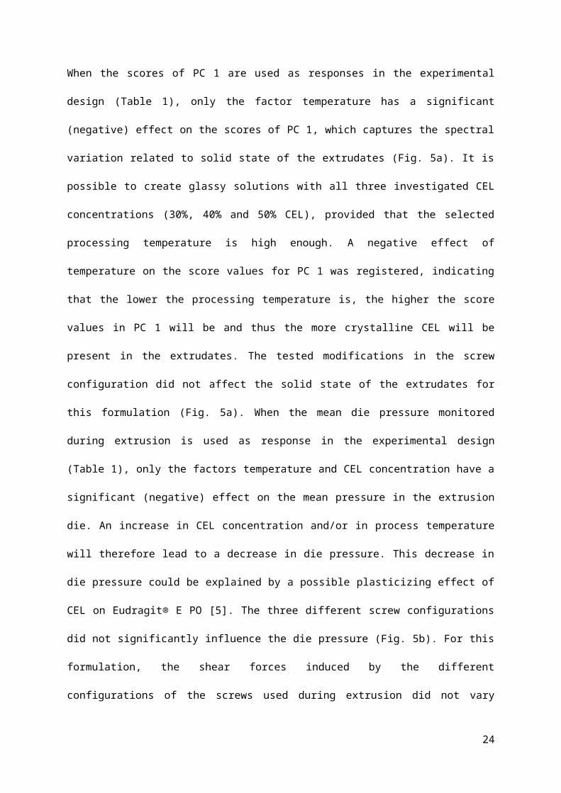
Figure 8. a) Coomans’ plot for the prediction of off-line measurements: distance of the new
observations in XRD (a) and DSC (b) measurements to the models with (y-axis) and without
crystalline CEL (x-axis)
Figure 9. a) PC1 versus PC2 scores scatterplot obtained after PCA of the off-line collected Raman
spectra after storage at room temperature for 1 year and b) PC 1 loadings plot.
Figure 10. a) PC1 versus PC2 scores scatterplot obtained after PCA of the in-line collected raw Raman
spectra. b) In-line collected raw Raman spectra with mean melt temperatures and die pressures.
Figure 11. PC 1 score values for the Raman spectra from the first principal component plotted with
the feed rate (kg/h) and the measured die pressure (bar).
24

Table 1. Performed extrusion experiments (full factorial (mixed) screening design).
Process and formulation settings Responses
Experi-
ment
Drug load Screw Barrel temperature profile Melt temperature Die pressure PC 1
number (% w/w) Configuration (feeding zone → die) (°C) in die (°C) (bar) Score values
1 30 FF 20-70-130-130-130-110 110,9 13,77 4,5461
2 30 FF 20-70-150-150-150-110 113,58 11,22 -3,4645
3 30 FB 20-70-130-130-130-110 111,31 18,28 2,6151
4 30 FB 20-70-150-150-150-110 114,2 16,36 -4,1576
5 30 2F 20-70-130-130-130-110 111,11 16,65 1,9484
6 30 2F 20-70-150-150-150-110 113,7 15,67 -3,1045
7 50 FF 20-70-130-130-130-110 111,35 16,89 8,7996
8 50 FF 20-70-150-150-150-110 114,06 7,75 -4,8359
9 50 FB 20-70-130-130-130-110 111 11,93 11,5758
10 50 FB 20-70-150-150-150-110 113,35 5,81 -5,7765
11 50 2F 20-70-130-130-130-110 111,18 14,45 8,0646
12 50 2F 20-70-150-150-150-110 113,55 7,11 -4,5921
13 40 FB 20-70-140-140-140-110 112,2 10,63 -2,3848
14 40 FB 20-70-140-140-140-110 112,01 10,77 -5,5010
15 40 FB 20-70-140-140-140-110 112,11 11,27 -3,7324
25

Figure 1. Applied screw configurations: FF, FB and 2F.
Figure 2. Experimental setup. 1) Extruder control panel, 2) Feeder control panel, 3) Feeder unit, 4)
Extrusion barrel, 5) Extrusion die with implemented Raman probe.
26

Figure 3. PC 1 versus PC 2 scores plots and loadings obtained after principal component analysis of
the XRD diffraction patterns (a and b) and on the DSC thermograms (c and d) from the end products
of each design experiment (experiment numbers according to Table 1).
27

Figure 4. a) PC1 versus PC2 scores scatterplot obtained after PCA of the in-line collected Raman
spectra and b) PC 1 loadings plot.
28

Figure 5. Significance of the influence of process parameters on a) the PC 1 scores obtained after PCA
on the in-line collected Raman spectra and b) the die pressure monitored during extrusion.
29

Figure 6. Coomans’ plot for the validation set: Distances of the new Raman observations to the
models with (y-axis) and without crystalline CEL (x-axis).
Figure 7. In-line collected Raman spectra during extrusion of 50% CEL at 130°C (purple) and 150°C
(green) and of 30% CEL at 130°C (red) and 150°C (blue).
30

Figure 8. a) Coomans’ plot for the prediction of off-line measurements: distance of the new
observations in XRD (a) and DSC (b) measurements to the models with (y-axis) and without
crystalline CEL (x-axis)
31

Figure 9. a) PC1 versus PC2 scores scatterplot obtained after PCA of the off-line collected Raman
spectra after storage at room temperature for 1 year and b) PC 1 loadings plot.
32

Figure 10. a) PC1 versus PC2 scores scatterplot obtained after PCA of the in-line collected raw Raman
spectra. b) In-line collected raw Raman spectra with mean melt temperatures and die pressures.
Figure 11. PC 1 score values for the Raman spectra from the first principal component plotted with
the feed rate (kg/h) and the measured die pressure (bar).
33