Embed Size (px)
Citation preview
Knight Sweeper 4200
University Of Central FloridaCollege of Engineering and Computer Science
Senior Design 1 Fall 2011Group 09
Phong LeJosh Haley
Brandon ReevesJerard Jose
Knight Sweeper 4200 Page 1

TABLE OF CONTENTS
1 Executive Summary
2 Project DescriptionSection 2.1 Project Motivation & Goals
Section 2.2 Objectives
Section 2.3 Project Requirments and Specs
Section 2.4 Project Management
Section 2.5 Project Financing and Budget
Section 2.6 Project Scheduling / Milestones
3 ResearchSection 3.1 Existing Solutions
Section 3.2 IED Detection System
Subsection 3.2.1 OverviewSubsection 3.2.2 Very Low FrequencySubsection 3.2.3 Pulse Induction Subsection 3.2.4 Beat Frequency Oscillation Subsection 3.2.3 Proximity Detector IC
Section 3.3 Obstacle Avoidance
Subsection 3.3.1 Ultrasonic Sensors Subsection 3.3.2 Infrared Sensors
Section 3.4 Power System
Subsection 3.4.1 Battery TechnologiesSubsection 3.4.2 Power DistributionSubsection 3.4.3 Power Regulation
Section 3.5 Wireless Communication
Section 3.6 Robotic Localization
Section 3.7 Digital Control System
Section 3.8 Robotic Control
Subsection 3.8.1 Chassis and Wheels Subsection 3.8.2 Motors Subsection 3.8.3 H-Bridges
Section 3.9 AI Navigation Algorithm
4 Project Hardware SelectionSection 4.1 Initial Design Architecture
Section 4.2. IED DetectionSection 4.3 Serial Camera SelectionSection 4.4 Power System
Knight Sweeper 4200 Page 2

Subsection 4.4.1 Battery SelectionSubsection 4.4.2 Power Regulation
Section 4.5 Wireless Communication SelectionSection 4.6 GPS SelectionSection 4.7 Compass SelectionSection 4.8 Microcontroller System
Subsection 4.8.1 MSP430Subsection 4.8.2 Stellaris Subsection 4.8.3 Concluding Remarks
Section 4.9 Motor ControllerSection 4. 10 Ultrasonic Range FinderSection 4. 11 Infrared RangersSection 4.12 Chassis and WheelsSection 4.13 MotorsSection 4.14 H-bridge
5 Design SummarySection 5.1 Software Architecture Overview
Subsection 5.1.1 Embedded SoftwareSubsection 5.1.2 PC SoftwareSubsection 5.1.3 PC Software / Embedded Software Message
Section 5.2 Hardware Architecture Overview
6 Project Prototype and ConstructionSection 6.1 Detection Circuit Design
Subsection 6.1.1 Obstacle AvoidanceSubsection 6.1.2 Metal Detection
Section 6.2 Power Systems Design
Section 6.3 PC Software Detailed Design
Subsection 6.3.1 Compass InterfaceSubsection 6.3.2 Message ParserSubsection 6.3.3 The GUI module
Section 6.4 Embedded Software Detailed Design
Subsection 6.4.1 Compass InterfaceSubsection 6.4.2 Exteneded UART InterfaceSubsection 6.4.3 OLED InterfaceSubsection 6.4.4 IED Detection InterfaceSubsection 6.4.5 Motor Controller Interface Subsection 6.4.6 Infra-Red Range FindersSubsection 6.4.7 Ultra Sonic Range FinderSubsection 6.4.8 Serial Camera InterfaceSubsection 6.4.9 GPS InterfaceSubsection 6.4.10 PC Serial Interface Subsection 6.4.11 Message Parsing ModuleSubsection 6.4.12 Telemetry ModuleSubsection 6.4.13 AI navigation Module
Section 6.5 Embedded/PC Communication Interface and Message Definition
Knight Sweeper 4200 Page 3

Subsection 6.5.1 Operation MessagesSubsection 6.5.2 Debugging and Manual MessagesSubsection 6.5.3 Concluding Remarks
7 Project Prototyping and TestingSection 7.1 Hardware Enviroment
Section 7.2 Hardware Test
Subsection 7.2.1 Obstacle Avoidance TestingSubsection 7.2.2 Motor Control InterfaceSubsection 7.2.3 IED Detection InterfaceSubsection 7.2.4 Power InterfaceSubsection 7.2.5 PC InterfaceSubsection 7.2.6 Chassis and WheelsSubsection 7.2.7 Motors and H-bridges
Section 7.3 Software Test
Subsection 7.3.1 PC, Embedded CommunicationSubsection 7.3.2 IR/ Ultra Sonic Ranger InterfaceSubsection 7.3.3 Metal Detector InterfaceSubsection 7.3.4 Motor Control InterfaceSubsection 7.3.5 Locational DataSubsection 7.3.6 Camera Module InterfaceSubsection 7.3.7 Navigational Artificial IntelligenceSubsection 7.3.8 PC Software TestingSubsection 7.3.9 Final Acceptance Testing
8 ConclusionSection 8.1 Participation
Section 8.2 Final Thoughts
Subsection 8.2.1 Phong LeSubsection 8.2.2 Josh HaleySubsection 8.2.3 Jerard JoseSubsection 8.2.4 Brandon Reeves
9 AppendicesSection 9.1 Work CitedSection 9.2 Image PermissionsSection 9.3 Table Of FiguresSection 9.4 Code libraries
Knight Sweeper 4200 Page 4

1. Executive Summary
The Knight Sweeper can serve several useful purposes and applications. The technology that will be used in Knight Sweeper can be found in many common consumer electronics. The main purpose of Knight Sweeper is to automate a metal detecting vehicle that has a autonomous start to end route and search the specified parameter for metallic materials. This function can be quite useful for either military application or hobbyist’s application. In case of military application Knight Sweeper could be quite useful in finding metallic objects such as mines, traps, or improvised explosive devices so that a safe path can be paved. The main components of Knight Sweeper is a rover 4 wheeled platform, a microcontroller unit, infrared sensors, ultrasonic devices, GPS unit, wireless module, and a metal detecting circuit.
The metal detector is composed of an integrated circuit with an internal oscillator. The external method of search for metal is done using a search coil that oscillates at a frequency which is close to that of the internal oscillation. A modern beat frequency oscillation method will then be utilized to determine detection of metallic objects. When detection occurs a bright LED will be lit, the rover will be flagged to stop its search path pinpoint the location of detection then run the algorithm to search for a new search path. Once detection occurs an analog output signal is sent to the main microcontroller unit to indicate that metal has been found. The microcontroller then records GPS location of detection and sends this information to the user interface which in return halts the actual rover vehicle for predetermined amount of time. Once the duration expires the pinpointed location will be removed from the vehicles search route and an alternate route will be determined and search will continue. The microcontroller also takes care of the controls of the rover vehicle through the utilization of a H-bridge design connector the a motor controller that controls vehicle acceleration and direction. Object avoidance will operate in a similar manner as the metal detection. Once the object is detected the microcontroller will be flagged and the rover will then cease to move until an alternate route is found.
The vehicle will be monitored on a personal computer through a custom GUI. From the interfacing of the personal computer the user will have the option to control the vehicle manually to override the autonomous mode. A visual view of the detection area as well as the pinpointed GPS location will also be available.
2. Project Description
2.1 Project MotivationImprovised explosive devices (IED’s) have been one of the primary causes of causalities in Middle Eastern affairs; about half of all American causalities in Iraq were the result of IED’s while in Afghanistan the figure is nearly two thirds. A improvised explosive device contains five components; a switch, an initiation, container, charge, and a power source.
Knight Sweeper 4200 Page 5

Improvised explosive devices are used to damage armored targets such as personnel carriers or tanks. Improvised devices are characterized by their employment.
The five employment techniques are coupling, rolling, boosting, sensitizing anti-tank mines, and daisy chaining. Coupling is the idea of linking one mine or explosive device to another. When the first device is detonated the other detonates by linkage. This technique is used to avoid countermine equipment. The rolling method is the act that one will roll pass the unfazed device and set off a second fuzzed device which detonated the over passed device underneath the vehicle. If the linked devices just so happen to be directional fragmentation mines a large lethal engagement area is created. The fourth method of employment is sensitizing antitank mines. Within this method it is often see that the pressure plate is cracked and the spring is removed to reduce the amount of pressure required to initiate the mine. The last method is the daisy chain employment which is the idea that mines may be used in daisy chains linked to other explosive hazards. When the initial mine is detonated the other mines detonate creating a larger lethal engagement area.
On top of the different methods of employment there are also different types of devices. The different types are explosive, nuclear, chemical, and incendiary. The explosive device is fabricated incorporating destructive, lethal, noxious, or incendiary chemicals to destroy areas nearby. Nuclear devices incorporate radioactive materials designed to disperse radioactive material or in the formation of a nuclear-yield reaction. Chemical devices incorporate toxic attributed of chemical materials that are meant to spread toxic chemical materials causing morbidity, mortality, or fear and behavioral modifications. Incendiary devices use exothermic chemical reactions designed to rapidly spread of fire for the purpose of creating primary patho-physiological effect on a large population.
Due to the idea that improvised explosive devices are truly improvised there is no specific guideline for explosive ordinance disposal. Explosive ordinance disposal personnel are trained in rendering safe and disposal of IEDs. Technology has been developed to counter improvised explosive devices such as IED jamming systems but since then terrorists have been able to improvise methods to counter such jamming systems by implementing physical connections between a detonator and an explosive device.
One of the early uses of improvised explosive devices was during the Vietnam War by the Viet Cong. IED’s were used against land and river borne vehicles as well as personnel. Thirty Three percent of United States casualties during the Vietnam war were due to IED or commercially manufactured mines. The three most used methods of explosives were the grenade in the can, rubber band grenade, and the Mason jar grenade. The grenade in a can is simply a hand grenade with the safety pin removed and a safety lever compressed and then placed in a tin can. The can was then fixed and a string was attached and stretched across a path. Once the grenade was pulled from the can by a person or vehicle through method of spring loading the safety lever would release and the grenade would then explode (MINE WARFARE IN VIETNAM)
Knight Sweeper 4200 Page 6

In Afghanistan the Afghan Mujahideen were supplied with large quantities of military supplies from the United States some of which being many various types of anti-tank mines. Explosives were often removed from anti-tank mines and combined with explosives in tin cooking oil cans for a more powerful blast. Methods of detonation were rarely through pressure fuses, most detonation was done by methods of remote triggering. Improvised explosive devices have become the most commonly used method of attack against NATO forces. According to a report by Homeland Security Market Research the number of improvised explosive devices used in Afghanistan had increased by 400% since 2007 and the number of troops killed by them also increased by 400%. (Combating the No. 1 killer of troops in Afghanistan)
In Iraq Improvised explosive devices were extensively used against coalition forces and by the end of 2007 responsible for almost 64% of deaths. IED’s were seen placed in animal carcasses, soft drink cans, and also boxes. As the technology of armored vehicle improved insurgents began to place IED’s in elevated positions on road signs or even trees so that damage was done to less protected areas. Even though armored technology has increased the deaths caused by improvised explosive devices still continue to increase. (More Attacks, Mounting Casualties)
Injuries sustained during a mine strike are caused by the pressure wave of the primary blast. During the second blast the penetrating and non-penetrating wounds are sustained. Combat medics when treating a victim of improvised electronic devices must be aware of multiple wounds and a combination of wounds that usually result from a mine strike. Additional to just wounds treatment of shock must be properly addressed.
2.2 Objectives
This project aims to design and implement an autonomous metal detecting robot with wireless connectivity and GPS logging with the purpose of detecting land mines and Improvised explosive devices. This involves the design and development of navigation AI, custom electronic interface design, and intelligent power mobile supply. After recent congressional budget cuts we feel this necessary topic to venture in. Our idea is to release our design to the public domain to those who have interest in related tasks.Our main objective is to create an autonomous vehicle capable of detecting IED’s and mapping a safe route between a denoted start and end point. IED detection will be done through sensors similar to those of a metal detector. Obstacle avoidance will also be a feature we plan on including which will be done using sensors to detect and avoid obstacles. Once an IED is detected its location will be pinpointed using a GPS module. A serial camera will be added to the design for output images and to be able to visual see the path of our vehicle. Integration of hardware and software will be done using an embedded system and software on a PC
Overall Objectives- Scan terrain for IED’s based on a start to end programmed route- Detect IED- Once IED is detected pinpoint location and paint grid area to notify detection
Knight Sweeper 4200 Page 7

- Avoid any obstacles that may be encountered during route of scan- Be able to navigate on desert like terrain and environments consisting of sand
2.3 Project Requirements
Below are the requirements we will try to meet while designing this vehicle. Along with meeting these initial requirements, we will try to meet more additional requirements as listed below if time permitted.
Initial Requirements
Knight sweeper shall be able to autonomously through a terrain Knight sweeper will operate on battery power (14.8 Li-Polymer battery) Knight sweeper shall be able to detect IED’s within a range of () Knight sweeper shall have a maximum weight of no more than 6 lbs. Knight sweeper shall avoid collisions with obstacles Knight sweeper shall be able to map its path and navigate to a destination via gps. Knight sweeper shall be able to communicate and send data to the user via
telemetry. Knight sweeper shall be able to operate in brightly lit environment Knight sweeper shall be able to operate both indoor and output Knight sweeper shall be able to operate for more than one hour on a fully charged
battery. Knight sweeper shall have a top speed for no less than 1mph Knight sweeper shall have a dimension of no more than inches Knight sweeper shall be able to operate in warm and cold climates.
Power Supply Requirements
The autonomous IDE detecting rover is going to be placed with the task of powering multiple powered electronic devices. There will be a power hungry camera and main driving motor that will be a great burden on the batteries. In addition, there will be multiple servos, microcontroller, and an obstacle avoidance system that will be competing for power from the battery. There are a few design requirements that will be met during construction of the Knight sweeper.
The power supply must last for at least an hour to give Knight sweeper time to complete a mission. The battery used in Knight sweeper must be able to fit on the bottom side of the chassis allowing space for other components. Knight sweeper must be able to maintain a regulated voltage during operation to avoid damage to electronics with differing power requirements. Knight sweeper must be able to function in Florida’s climate.
Knight Sweeper 4200 Page 8

Obstacle Avoidance Requirements
Obstacle avoidance is a vital task in the successful completion of a mission. If the rover does not detect and avoid obstacles it could severely comprise the integrity of a mission as Knight sweeper may run into a wall or large rock and become immovable. Below is a list of requirements that will be needed for successful obstacle avoidance.
Small enough to fit on the chassis without interfering with other components
Able to detection objects within a range of 180 degree from Knight sweeper.
Easy to test and interface with our selected microcontroller Be able to run off of our 5 volt DC power supply
IED Detection Requirements
Metal detection is used to detect any metallic object for means of simulation of improvised explosive device detection. Below is a list of requirements that must be met in order for Knight Sweeper to achieve success in its overall purpose.
Detection must occur within a minimum of 5 inches in front of the actual rover
Battery life must last for as long as the rover is operational Must be able to communicate output with the microcontroller Weight of the metal detection circuit must be under 18 ounces Power consumed by the metal detector must be under 12 watts Search coil of the detector must be placed in front of the actual rover
Specifications
Hardware: Aluminum chassis Four wheels, 2 inch diameter Two servo motors, robot moves at 4inches/sec with variable speed control
and differential steering Digital video camera with resolution up to 640×480 pixels Infrared sensors for obstacle detection and navigation (using beacons
along routes) Zigbee USB 802.15.4 wireless module (Range 100m indoors and 1000m
line-of-sight) Connectivity -- RS-232 or USB 14.8 VAh Li-on battery packs, provide up to 3 hours of operation Host PC runs on Windows
Knight Sweeper 4200 Page 9

Software:
Design Embedded Program in C Embedded Program must run in a small memory space and fit in onboard
flash. Must be robust to possible errors. Must successfully navigate the robot toward its goals. Reliable communication with PC software.
2.4 Project Management
For project management purposes we broke down the overall project into six different phases. Those phases are research, design, material acquisition, prototyping, testing, and integration. Within each project phase are tasks of the project which have each been assigned to individuals who will hold accountability for that particular task. These task names and people responsible for them are listed below.
Motor JerardIED Detection PhongObstacle Avoidance BrandonGPS JoshPower BrandonSerial Camera JoshMain Board Josh
The goal of each member being assigned a particular task is to ensure that each member has a contribution to the overall completion of the project. Weekly meetings are held to discuss progress, potential problems, and explanation of design to ensure that we are all updated with each individual’s progress.
2.5 Project Financing and Budget
Our project funding is sponsored by Work Central Florida. Work Central Florida is an organization with authority for workforce planning, programs, and labor market. Work Force Central Florida has a large pool of talent for which they try to connect with employers to provide work resources and training. Work Central Florida gives the community of Orlando the proper preparation meeting up to the demands of businesses for today and the future
QTY DescriptionActual Cost
Estimated Cost
Estim Total
Knight Sweeper 4200 Page 10

(unit) (unit) Cost
2 Robot Base Platform $ 270.00
$ 540.00
1 PCB FAB $ 370.00
$ 370.00
2 Lithium Battery ( 12v 4000mah $ 150.00
$ 300.00
1 Lithium Charger $ 90.00
$ 90.00
2 XBee Module $ 60.00
$ 120.00
2 Stellaris M3 + Dev Board $ 130.00
$ 260.00
2 GPS Module $ 80.00
$ 160.00
2 Power Supply $ 120.00
$ 240.00
2 Serial cameria $ 50.00
$ 100.00
1 Matlab & Simulink (student) $ 170.00
$ 170.00
1 SolidWorks (student) $ 150.00
$ 150.00
1 MS Office (student) $ 150.00
$ 150.00
1MISC Electrical Parts (caps, resistors, perfboards)
$ 100.00
$ 100.00
6 Sonar sensor $ 35.00
$ 210.00
3 Infrared Senors 13,95 $ 20.00
$ 60.00
4 Breadboards $ 35.00
$ 140.00
2 Soldering Materials(iron, flux, solder) $ 40.00
$ 80.00
1 Plexiglass Chassi $ 150.00
$ 150.00
1 MISC mechanical Hardware $ 120.00
$ 120.00
1 Tools(drill bits, knife) $ 50.00
$ 50.00
1 Misc hardware (for mcu test box) $ 60.00
$ 60.00
1Voltage reg, battery post, terminals, breadboard (for mcu test box)
$ 30.00
$ 30.00
Knight Sweeper 4200 Page 11

Total Estimated Cost $ 3,650.00
2.6 Project Scheduling / Milestones
As a group it was decided to break the project scheduling and setting of milestones into 5 major portions. The 5 major portions are Research, Design, Materials acquisition, Testing, and Implementation. Each portion of the project can be seen as a stage of the timeline of the actual scope of the project. Within each of the 5 major portions are the actual different components of the entire project. These components are IED detection, obstacle avoidance, power system, wireless communication, GPS module, microcontroller, robotic controls, and the AI controls systems. Each of these components has an assigned individual to be accountable and responsible for its completion. We chose to have it this way so that each group member will have their own part of the project for which they will be responsible for. The work is divided evenly and updates on progress are done at weekly meetings.
-RESEARCH
The research portion timeframe is set to be completed in the duration of 2 months. During this portion of the project we will be looking into existing solutions and the technology behind the components of our project. Based on the research done we will start designing the different components of Knight Sweeper. The project’s subsections are set to be 100% complete by the date of 10/31/11.
Knight Sweeper 4200 Page 12

-DESIGN
The design portion of the project is set to be completed in about 2 months. The actual design stage can’t officially start until all the research is completed. During the design stage we will be looking into various methods that each component can be designed. These methods will be brought up at our weekly meetings and as a group it will be decided which design will be more beneficial. The project’s subsections are scheduled to be completed by the date of 12/28/11.
-MATERIALS
The materials portion of the project is set to be completed in about 2 months. The actual stage of material acquisition can’t officially start until all the design is complete. Materials will be ordered in the order of lead time. If one part has a long lead time it will be moved in early priority for order in case it affects any of our schedule milestones. Parts must be ordered and shipped by the date of 01/25/12.
Knight Sweeper 4200 Page 13

-TEST
The actual testing portion of the project depends on completion of design and materials portion of scheduling. Testing is where we will be building to our design and seeing if it actual works in the manner we set in our specifications and requirements. Each subsection within the testing stage will have its own unique testing procedure. Testing of the actual project is projected to be completed by 3/7/12.
-IMPLEMENT
The last stage of our project is the implementation portion. This portion will take place after completion of the testing of our design. Implementation is the last and final stage of our project and during this stage is where everything comes together. Each component will be interfaced after testing to ensure that the rover functions in entirety. The project is projected to be implemented and completed by the date of 4/25/12. We chose an aggressive schedule to arrive at an early completion in case any major problems randomly occur.
Knight Sweeper 4200 Page 14

3. Research
3.1 Existing Solutions
There has been robots design to detect improvised explosive devices already. Based of off existing solutions we can learn and get a good idea about what kind of details we need to pay attention too. Having the option of being able to reference something gives more room to improve design functions.
One of the projects developed by Advanced Robotic Systems International was one with the functionality of removing mines left over from previous wars. The robot was built to navigate through rough terrain of vast size. Two arms were designed to detect mines and both were operated through remote control. The first arm was an actual sensor for detection and the second with was confirmation. Confirmation by the second arm was done by using tools that would probe the ground without actually detonating the mine. Mobilization is done using wheels with a caterpillar like track. The tracks are able to rotate up and down allowing the physical robot to maneuver without tiling to the side.
The first arm of the robot which is the sensing arm is known as the Selective Compliant Articulated Robot Arm, this arm allows for a large range of motion that allows for large areas to be scanned all at once. The way the sensor on the arm functions is one sensor is used to detect distance between the robotic arm and the ground while the second sensor adjusts itself for distance to detect mines inside the ground. The robot controller is used to monitor the distance of the sensors and constantly adjust itself when needed by the user. The controller is also used for means of transmitting data to a Personal computer. A crash sensor is added to ensure that the arms never collide while being controlled by the user. Location of detection is logged through means of GPS.
Another similar project is an autonomous mine detection robot for humanitarian demining. The purpose of this particular project was to develop a method using robotics to get rid of mines in areas where people are physically demining themselves. The usual method of getting rid of mines in foreign countries consists of people physically locating the mines. The main intended use of this particular robot is to prevent the risk and danger of humans removing landmines themselves. The physical body of the robot consists of six robotic arms that have a spider like shape. The six arms are used for means of maintaining stability. Two of the arms in the front serve for means of mine detectors. Two arms consist of sensors that consist of metal detecting and also a ground penetrating radar. The ground penetrating radar is used to provide a clear image of the mines. Once detection of a mine occurs one of the arms spray paints the spot and marks the detected mine. Like the first robot mention a system of tracks is attached for use of balancing in case tilting occurs.
The last existing technology researched was an integrated Robotic System for Antipersonnel Mine system. This project was developed through a collaboration of research groups from various universities. The project was developed to serve as a mine detector that didn’t need human intervention. This particular robot also used the method
Knight Sweeper 4200 Page 15

of Group Penetrating Radar and metal detectors as a mean of locating and detecting land mines. The body of the robot was a three wheel system which moved in all directions, Omni directional. The position of the three wheel system allowed for full 360 degree rotational ability. Movement is operated via joystick which is attached to a “HMI PC”. The other control systems are the location system and vehicle system which delivers data to the actual computer. The location system develops a map of the area and marks location of all mines found in route. A camera is used to be able to see a colored ball which is mounted on the robot to allow it to see the map as the robot moves. Each frame from the camera that is seen turns into an extracted position from the image of the ball. The vehicle system deals with the actual detection of mine and is also the actual robotic platform. Movement is controlled by a microcontroller while the sensors interfaces with an Embedded computer on the robot. The embedded computer then interfaces with the actual HMI PC.
3.2 IED Detection System
3.2.1 Overview
Our project application is to autonomously detect improvised explosive devices (IED) which is also known as roadside bombs or homemade bombs. Although not all of the improvised explosive devices are composed of metal most actually do have metal casing or substantial metallic content. Detection of nonmetal improvised explosive devices requires various sensors and other detection technologies that we do not plan on using. Some of these technologies are thermal, chemical, or ground penetrating radar imagery. These technologies pose great difficulty and complexity that is beyond our scope or budget. Nevertheless metal detectors remain the most commonly used form of tool to detect improvised explosive devices which is what we plan on utilizing. Our project is specifically designed to detect improvised explosive devices that are composed of metallic materials. The limitation of material is due to scaling the project to a degree that we can accomplish within the allotted time and also budget factors.
Metal detectors are usually used to find hidden metal items. These items are usually lost treasures found on beaches or historic sites. The way metal detectors operate are by sensing changes in magnetic waves caused by the metals. Some methods of metal detection are more sensitive than others. The three most common methods are VLF (Very Low Frequency, PI (Pulse Induction), and BFO (Beat Frequency Oscillation). The goal of selecting the ideal metal detection design was to create a circuit capable of detecting metal that is battery powered. On top of that, an easy compact circuit designs so that we can fit all the sensor related interfaces onto one printed circuit board.
The first industrial use of a metal detector was during the period of 1960 were they were used for application of mining and other various industrial applications. These uses include detection of land mines, detections of weapons to assure security, geophysical prospecting, archaeology, and treasure hunting. They may also be seen commonly used to detect steel bars in concrete, pipes, and wires buried behind a surface such as a wall.
3.2.2 Very Low Frequency
Knight Sweeper 4200 Page 16

Very low frequency detectors can be one of the most versatile compared to the other two methods. This is due to the range of metal detection that it provides. The way the design works is a method of induction balance using very low frequencies. Two coils are combined the outer one act as a transmitter using alternating current to create a magnetic field that gets distorted by any metal object. As current changes direction, polarity of the magnetic field also changes. For example if the coil of wire is parallel to the ground the field begins pushing down towards the ground and pulls back out. As the magnetic field pulses back and forth it then reacts once it detects a conductive object causing a generated small magnetic field. Depicted in figure 1 is a commercial example of a Very Low Frequency metal detector.
Figure 1(You are free to display and print for your personal, non-commercial use information you receive through the
Discovery Sites.)
The inner coil acts as a receiver for this disturbance and also reads the secondary magnetic field caused by the conductive object but it shielded from the magnetic field that the transmitter coil generated. Once an object is detected a small current travels through the receiver coil this current then oscillates at the same frequency as the magnetic field. The closer it is towards the surface of the object the stronger the magnetic field becomes and the stronger the current generates. Once the field is amplified it is outputted in a form of audio. An electric circuit can be used to tune out signals that need to be ignored, and focus on the desired ones. Different types of metals tend to emit different types of signals.
Knight Sweeper 4200 Page 17

Figure 2(You are free to display and print for your personal, non-commercial use information you receive through the
Discovery Sites.)
Figure 2 gives a description as well as depicts how VLF metal detections function. “As the magnetic field pulses back and forth into the ground, it interacts with any conductive object is encounters causing them to generate a weak magnetic field of their own. The polarity of the objects magnetic field is directly opposite of the transmitter coil’s magnetic field. If the transmitter coils field is pulsing down, then the objects field is pulsing up”. (How Metal Detectors Work )
3.2.3 Pulse Induction
The second method of metal detection tends to be that which is more specialized for users trying to seek metal objects deep under a surface. Large versions of pulse induction detectors are those used at security checkpoints to detect weapons. Pulse induction detectors usually only use one coil unlike that of a very low frequency detector. Very similar to that of the Very Low Frequency detector one coil sends out a magnetic field towards the ground once a metal underground reflects the signals the pulse induction unit quickly switches to listen mode for the reflected signal. This method sends pulses of current through the coil wire each pulse generating a magnetic field. After each pulse the field reverses polarity and collapses resulting in a sharp electric spike. One the pulse induction detector is over a metal object the pulse then creates an opposite magnetic field in the object then the pulse collapses causing reflected pulse to last longer to completely disappear. Below depicted in figure 3 is an example of a commercially used pulse induction metal detector.
Knight Sweeper 4200 Page 18

Figure 3(You are free to display and print for your personal, non-commercial use information you receive through the
Discovery Sites.)
This method is very similar to the way an echo is heard. An electric circuit is utilized to monitor the length of the reflected pulse. A comparison between expected lengths determines if another magnetic field caused reflected pulse to delay. If an abnormal delay is seen, one can assume that a metal object was detected. Pulse inductions are not as reliable in discriminating between metals as the very low frequency is. But unlike the very low frequency detector pulse induction is very useful in situations that have highly conductive materials in the environment of detection. High conductive materials may cause an inconsistency when dealing with detection. The fact that Pulse Induction doesn’t react to the disturbance in magnetic field that may be due to conductive materials in the environment proves to be very beneficial in certain applications. Due to our primary goal of detecting Improvises Explosive Devices, extreme accuracy is essential and absolute limitation of percentage of error almost has to be nonexistent.
Knight Sweeper 4200 Page 19

Figure 4
(You are free to display and print for your personal, non-commercial use information you receive through the Discovery Sites.)
The figure above is a description as well as a picture of how detection is done through pulse induction. “If the metal detector is over a metal object, the pulse will create an opposite magnetic field in the object. When the pulse’s magnetic field collapses, causing the reflected pulse, the magnetic field of the object adds, to the length of time that it takes the reflected pulse to completely disappear, think of this process like echoes.” (How Metal Detectors Work)
3.2.4 Beat Frequency Oscillation
The third type of metal detection is Beat Frequency Oscillation. This type of detector is the most inexpensive and simplest design of the three. Very similar to that of the very low frequency detector, beat frequency oscillation uses two separate coils for method of detection. An Oscillator creates a constant signal at a set frequency. The two coils are attached to an oscillator that generates thousands of pulses of current person second. The frequency of each pulse is an offset between the two coils. As the pulse travels a radio wave is then generated. These radio raves are then picked up by a receiver and then converted into a series of tones based on the difference between frequencies. Once the coil detects a metal object the magnetic field caused by the current through the coil another magnetic field is generated around the metal object. The objects magnetic field disturbs that of the radio waves frequency generated by the search head coil. As frequency begins to deviate from the frequency of the second coil the audible beats begin to change in duration and tone.
Frequency stability of each individual oscillator is important due to the idea that detection is based on frequency variation. To minimize frequency drift difference each individual oscillator should have high inherent stability with taking into account variation of temperature and voltage variations. Another main factor that affects beat frequency oscillators are whistles which are spontaneous beat notes. These whistles are due to the cross-modulation by the mixer within the AF amplifier. Whistles can be eliminated by
Knight Sweeper 4200 Page 20

programming the mixer to minimize RF harmonics or by filtering to prevent harmonics generated from the mixer to reach the amplifier circuit.
Figure 5
(You are free to display and print for your personal, non-commercial use information you receive through the Discovery Sites.)
Depicted in figure 5 is a description as well as a picture of how beat frequency oscillators work. “ If the coil in the search head passes over a metal object the magnetic field caused by the current flowing through the coil will create a magnetic field around the object. The objects Magnetic field will interfere with the frequency of the radio waves generated by the search head’s coil. As the frequency deviates from the frequency of the coil in the control box, the audible beats will change in duration and tone.” (How Metal Detectors Work)
Comparison
Three metal detection methods were described above, Very Low frequency, Beat frequency oscillations, and Pulse induction. Very Low frequency is one of the most commonly used in metal detection but it relies on phase shifting for metal detection. Objects that have high inductance may have a larger phase shift that react slowly to current change. Higher resistances cause a faster reaction but smaller phase shift. The most basic method on the other hand is beat frequency oscillation detection. One disadvantage of Beat frequency oscillation detection is that you do not have control of sensitivity based on functionality. The last detection method is Pulse Induction detection which is one widely used by hobbyists as coin detectors and is also commercially available. Each of the three options prove to be very useful in the application of simulating detection of improvised explosive devices. Although each method of detection is very unique and has different operating specifications that the other may not have.
Knight Sweeper 4200 Page 21

3.2.5 Proximity Detector Integrated Circuits
Proximity detector integrated circuits are also a solution when it comes to designing a metal detection circuit. These proximity sensor are basically Beat Frequency Oscillator metal detectors in a small compact format. Using an integrated circuit in our design could potentially decrease the size of our actual fabricated PCB board. Based on research done the existing integrated circuits that are used as proximity detectors are the CS209A, TDA0161, and also the STEVAL-IFS005V1.
CS209A
The CS209A is a bipolar monolithic integrated circuit which is often used for metal detection or proximity sensing applications. Within the CS209A is two current regulators, an oscillator, a peak detection/demodulation circuit, a comparator and two complementary output stages. The oscillator within the circuit provides controlled oscillation. The amplitude of the oscillation is dependent on the quality factor of the inductor capacitor external circuit. If the quality factor is low, a feedback circuit inside the chip provides the main drive to the oscillator. Within the inner workings, the peak demodulator senses the negative side of the oscillating wave and provides a demodulated waveform to the input of the comparator. The comparator then sets the states of the outputs by comparing the input from the demodulator to an internal reference.
Features: - Separate Current Regulator for Oscillator - Negative Transient Suppression - Variable Low-Level Feedback - Improved Performance over Temperature - 6mA Supply Current Consumption at VCC = 12V - Output Current Sink Capability - 20mA at 4VCC - 100mA at 24VCC
Commonly encountered metals-Stainless steel 0.101”-Carbon Steel 0.125”-Copper 0.044”-Aluminum 0.053”-Brass 0.052”
The CS209A integrated circuit is a metal detecting circuit which operates on the idea of detecting a reduction within Q of an inductor when encountered by metal.
Knight Sweeper 4200 Page 22

TDA0161
The TDA0161 is another integrated circuit that can be utilized for metal detection. This particular integrated circuit detects through variation of high frequency. Externally turned circuits added act as oscillators and output signal is altered by metal object detection. Output signal is determined once metal detection alters supply current.
Features: - 10mA Output current - Oscillator frequency of 10MHz - Supply voltage of +4 to +35V
The TDA0161 functionality is very similar to that of the BFO schematic proposed in our initial design. The main difference between the BFO circuit and the TDA0161circuit is the fact that with the BFO circuit oscillating frequency can be customized to specific application demands. But the idea of multiple parts versus one comes into play when dealing with faulty components. With the TDA016 there is only one component in concern and the main search coil may be designed to an oscillation of your choosing.
Figure 6Requested permission from STMicroelectronics
Figure 6 above is a pin layout for the TDA0161. Between the pins of 3 and 7 the integrated circuit acts as a negative resistor with a value equal to that of the external resistor of R1 which is connected to pin 2 and 4. Oscillation stops when the circuit loss resistance RP becomes smaller then that of R1.
DETECTION RANGE
L1 (μH)
C1 (pF)
fOSC (kHz)
R1 (kΩ)
C2 (pF)
2MM 30 120 2650 6.8 475MM 300 470 425 27 47010MM 2160 4700 50 27 3300
Knight Sweeper 4200 Page 23
Figure 7Requested permission from STMicroelectronics
Figure 7 depicts the actual circuit within the integrated circuit of the TDA0161. You can notice that the detector is directly connected to the oscillator. This is because the oscillator generates pulses of current that generate radio waves. As this is all taking place a receiver picks up the radio waves and creates an audible of series of tones based on different within frequency.
3.3 Obstacle Avoidance
Ultrasonic and Infrared sensors are among the most common sensor technologies used among hobbyists. Here we will discuss the physics behind both along with comparing both infrared and ultrasonic technologies.
3.3.1 Ultrasonic Sensors
Ultrasonic sensors are relatively simple devices. The sensor sends a pulse out; the pulse will then be reflected from objects in its immediate path. When the pulse is emitted from the device it travels through the medium until it collides with an object causes the pulse to be echoed back. Once the system receives the reflected the reflected wave, then the
Knight Sweeper 4200 Page 24

time difference between the firing of the pulses and the receiving of the reflected wave is proportional to the distance of the objects. Pulses can range from 40-200kHz but for most practical applications they are typically found to be in the range of 40-50 kHz.
The equation below is used calculate the distance of the obstacle, v is the speed of sound in air and t is the time between the fired pulsed and detection of the reflected wave, theta is the angle of incidence between the wave and obstacle. The infrared sensors will be used an alternative means for collision avoidance.
Block diagram for Ultrasonic Sensors
Figure 8
The piece of hardware that sends out the orginal pulse and senses the returned pulse is called a transducer. The two type of transducers commonly used are electrcosatic and piezo transducers. Electrostatic transducers are similar in structure to capictors. They consist of two plates, where one is fixed and one is movable. The fixed plate is usually constructecd out of aluminum while the movable plate is Kapton coated with a thin gold layer. The Kapton acts as an isulator in the movable plate. Applying a signal to the plates causes the layer of gold foil to be attracked to the backplate which cases a displacment of air and creates the ultrasonic burst.
In contrast to electrostatic transducers, piezo electric transducers use the peizo effect to create and measure the ultrasonic pulzes where a peizoelectric substance is one that
Knight Sweeper 4200 Page 25

produces an electric charge when a mechanical stress is applied. These sensors use a crystal or cermanic material that is bonded to a metal case. When a signal is applied to a signal which causes the the piezo material to contact or expand. Similarly the connected metal case also contracts or expands which generats the ultrasonic burtst. The return pulse causes the piezo material to vibrate which generates a signal. These tranducers are typically less expensive than the previously mentioned electricostatic transducrers in additon their construction makes them better suited for unfavoriable enviorments .
Ultrasonic sensors also have inherent limitations. These limitations are directly related to the cone shape of the emitted pulse. A major issue is anything in the pulses path will trigger feedback from the sensor so there is no way to discern a wall from a small obstacle, as both will reflect the pulse. A simple solution to this is to either employ rotating sensors or multiple sensors on a system. If multiple sensors are used they can be placed at a single point with different angles thus giving a better idea of where the detected object is.
3.3.2 Infrared Sensors
Infrared sensors (IR) used infrared radiation, which is part of the electromagnetic spectrum. There are two types of IR sensors, IR sensors with built in circuitry that outputs a binary result and those that provide an analog output or multiple bit output.
Sensors with a binary output are best at detecting the proximity of an object but not necessarily the range. Thus this type of sensor can output a threshold distance, this sensor are among the cheapest IR sensors. The other IR sensors fall into the category of ranging sensors, which return an output of the actual distance from the sensor to the object. This output can be returned in either an analog or digital byte.
Many IR sensors work by the process of triangulation, a pulse of light is emanated from the device and is either reflected back or not reflected at all. When the light is reflected back it returns at an angle that is dependent on the distance of the object is reflected off of, which is depicted by the figure below. Triangulation works by detected this reflected beam angle, once the angle is known the distance can be calculated.
Block diagram for Infrared Sensors
Knight Sweeper 4200 Page 26

Figure 9
A major limitation is infrared sensors are the decreased beam width compared to ultrasonic sensors. This means to detect an object the sensor has to point directly at the obstacle. Another limitation of most IR sensors are the non-linear outputs, this means that as distance increases linearly by set increments the output decreases and decays nonlinearly. One last difficulty that arises is that IR sensors often have a minimum distance where they cannot detect an obstacle, this can be overcome by not mounting the sensors flush on a robot but inside in a recess.
3.3.3 Ultrasonic vs. Infrared Sensors
Both means of obstacle avoidance have their own advantages and disadvantages, in this section will compare both Ultrasonic and Infrared sensors to determine which is a proper fit for Knight sweeper. As previously stated infrared sensors emit light that is emitted in a triangular pattern. The light travels until it is reflected back by and object and the distance of the object is dependant on the angle that the light is reflected back to the sensor. The main advantage to using these IR sensors is the cost, as they are not as versatile as ultrasonic sensors. Many infrared can be purchased for under $20, which makes them very economical to add to a project. As previously mentioned infrared sensors present many draw backs such as the fact that light reflects differently off objects of varying sizes and material compositions. There may also be discrepancy of reading on objects of various colors even if they are detected at the same distance. The biggest drawback in IR
Knight Sweeper 4200 Page 27

sensors is the extreme sensitivity to direct sunlight that can cause inaccurate readings. In contrast ultrasonic sensors emit a high frequency pulse instead of beam of light, which is more appropriate for outside use. Although ultrasonic sensors possess their own set of disadvantage first they are significantly more expensive than their counterpart infrared sensors. Ultrasonic sensors can typically run up to $50 more than twice the price of IR sensors. Ultrasonic sensors also show difficulty when trying to detect objects made of materials that absorb sound such as foam, in that case the pulse would not be reflected back thus no reading will have occurred. Overall ultrasonic sensors appear more advantageous to Knight sweeper than infrared sensors, which is why they will be the primary means of obstacle avoidance. Accuracy is among the most important of these advantages, in addition to the gained accuracy ultrasonic sensors are not affected by light and furthermore ultrasonic sensors have more versatile ways of interacting with microcontrollers such as UART and I2C interfaces as well analog pulse width modulation and a RS232 serial output. . Infrared sensors will be used a means of secondary and lateral obstacle avoidance which is not as pertinent as forward avoidance.
3.4 Power System
Knight Sweeper will need to operate freely, this means that all devices on-board will need to be powered wirelessly. The following will discuss power considerations for elements in need of an electrical configuration. These elements include the brushless DC motors, microprocessor, ultrasonic sensor and infrared sensors, compass, serial camera, and GPS system
3.4.1Battery Technologies There are many different types of batteries that may be used for robotic functions. A battery itself is rated according to voltage and current supplied. To create more voltage batteries are connected in series and to create more current batteries are connected in parallel. Rechargeable batteries have been around for many years and are continuing to improve as the year’s progress. A battery consists of a negative and a positive electrode each of which is made of a different material. The difference in material causes a chemical reaction within the battery internally. Electrolytes remain internally inside the battery and are the catalyst to the chemical reactions within the actual battery. This reaction causes the electrolytes to transport ions from one electrode to the other. Through this transformation is how stored chemical energy converts into useable electricity. In our case we chose to go with rechargeable batteries versus ones that can’t be recharged due to the idea that we are interested in multiple trials. Normal batteries that require constant replacement may pose to be expensive due to the amount of trials we intend to run causing it to potentially be very expensive in the long run. Another important factor that is important in our application of use is the power rating. For this particular application a battery with a high number of milliamps per hour but be chosen.
Knight Sweeper 4200 Page 28

Delivery of current via battery is done through continuous electron flow. The negative electrode (anode) releases electrons during the chemical reaction while the positive electrode (cathode) absorbs electrons. Reactions vary based upon the battery. Below is a list of specifications to look at when selected a proper battery - Shape of battery based on platform- Durability, how many times the battery can efficiently be charged/reused- Charge Capacity. Capacity of the battery pack in milliamperes-hour determines
how long the rover will run before losing power.- Initial cost, paying more is an option if it adds efficiency- Environmental, must take into consideration of proper disposal
Based on the specifications listed above, there will be four different types of batteries that will be researched upon. The four types are NiCd, NiMH, Lithium Ion, and Lithium Ion Polymer.
NiCd
A well know flaw within NiCd batteries is the idea of “memory effect” which is the cause to the battery losing charge faster as it ages relative to when it was brand new. Memory effect is the misconception of your battery thinking its fully charged but really it is not. It has been found that a key factor to the cause of the “memory effect” is Cadmium, cadmium is also very heavy and very toxic. Within a NiCd battery the negative and positive electrodes are set apart by a separator soaked with electrolytes. Once charged the cathode contains nick oxyhydroxide (NiOOH) and the anode contain cadmium. Cadmium atoms at the anode dissolve in the electrolyte and transform into positive ions therefore releasing two electrons.
At the cathode another reaction takes place during the discharge of the battery. This reaction involves two electrons combined with nick oxyhydroxide and water to form nickel hydroxide. During the recharge of these batteries reactions are reversed and the original structures of electrodes are restored. The charger of the battery causes an inverse in the direction during discharge and reverses all chemical reactions. After multiple recharges the battery may deteriorate and become unusable. A second alternative are NiMH batteries. Below in figure 11 illustrates the internal and external parts of NiCd batteries. (The Truth About NiCd Batteries)
Knight Sweeper 4200 Page 29

Figure 10Courtesy of hamradioindia
Charge
NiCad batteries are best charged when using a constant current. It is also recommended that NiCad batteries be charged at a temperature of 20 degrees which is room temperature. If the actual batteries is physically too cold or too warm then a smaller percentage of charge will be retained. Normal charge conditions call that a NiCad battery be charge at an initial voltage of 1.2v to and end point of 1.45volts. As charge current is applied to the battery current gets stored. But constant charge will progressively weaken the batteries ability to store energy. Overcharge causes crystals to grow between the plates and cells become shorted.
Discharge
Before charging cells of NiCad batteries each cell should be fully discharged. NiCad batteries have a tendency to fully discharge themselves over time. Discharge rates of 2% per day have been seen in some cases.
Retention
NiCad batteries suffer from the memory effect condition if they discharge and recharge at the same state of change hundreds of times. The capacity of the batter becomes substantially reduced over periods of time. If treated in ideal situations NiCad batteries are theoretically supposed to last for a solid 1000 cycles or more before capacity drops below half its original capacity.
NiMH Nickel metal hydride batteries are very similar to that of NiCd batteries. The nominal voltage of Nickel Metal Hydride is the same as nickel cadmium batteries which is 1.2 volts. Within Nickel Metal Hydride batteries an internal resistance exists that produces
Knight Sweeper 4200 Page 30

high current surges. The positive electrode contains nickel. But unlike NiCd batteries the negative terminal doesn’t have cadmium; it uses a hydrogen absorbing alloy. The reaction within the positive electrode is very similar to that of NiCD. Water molecules become ionized, protons and electrons attach to NiOOH to form Ni(OH)2. The negative electrode reaction involves metal releasing stored hydrogen and combining with a OH- ion to form water which leads to freeing an electron. NiMH batteries are ideal for applications such as camera flashes, RC vehicles and power tools. NiMH also has a capacity that is three times that of Nickel Cadmium.
A huge benefit of using nickel metal hydride is the idea that it does not have any memory effect meaning it can be recharged multiple times. An average recharge period of nickel metal hydride batteries is rated for approximately 1000 cycles. Although with every advantage always comes a disadvantage. Nickel Metal Hydride Batteries are seen to be less durable and suffer a high self-discharge rate. Limited service life is seen and performance begins to deteriorate after being cycled. Each month Nickel Metal Hydride batteries loss about 30 percent of their initial charge just sitting on the shelf.
Charge
The charging voltages of NiMH batteries are within the range of 1.4 to 1.6 volts per cell. Constant voltage charging method can’t be used for methods of automatic charging. The most efficient way to charge NiMH cells is with a low fixed current. Chargers for NiMH cells must know when to stop charge in order to avoid damaging the battery. A method of doing such a thing is to monitor change in voltage across the battery over time. Once the battery fully charges voltage across the terminals drop.
Discharge
Like NiCad batteries NiMH batteries have a level of self-discharge over a period of time. Some factors that contribute to this discharge is energy used during oxygen cycles of high states of charge. Long term contributions are caused by chemical ion shuttles which continuously discharge the cell over long periods of time.
NiCAD vs NiMH Batteries
NiMH batteries do not handle the high rate of charges that NiCAD batteries can. NiCAD batteries tend to use high rate, peak detection, or time-based chargers which would potentially damage NiMH cells permanently if used to charge NiMH batteries. NiMH discharge rate is greater than that of NiCAD by almost a factor of 2. Because of this discharge rate you often find yourself charging your NiMH battery each night before use. If both batteries are used in ideal use NiMH batteries can proof to be quite beneficial providing much longer run times than NiCAD batteries. NiMH batteries tend to be recommended when using applications that involve long durations and a low amp load. NiCAD batteries are usually recommended in applications where a lot of amps are needed.
Knight Sweeper 4200 Page 31

Lithium Ion Battery
Lithium Ion batteries (LIB) are rechargeable battery that moves from the negative electrode to the positive electrode during discharge and then returns once charging. Lithium Ion batteries may be seen commonly used in daily consumer electronics. They contain very efficient energy densities without any signs of memory effect. An advantage seen in lithium ion batteries is the fact that it comes in different shapes and sizes.
Lithium Ion batteries are primarily composed of three components anode, cathode, and electrolyte. The anode containing carbon, the cathode containing metal oxide, and the electrolyte is a lithium salt in an organic solvent. Pure lithium itself has a very reactive property that reacts with water to form lithium hydroxide and hydrogen gas. Due to this packaging is typically built to seal off any potential water from the battery pack. The anode and cathode are made so that lithium can migrate in a bi lateral manner. During lithium based cell discharge lithium itself Is removed from the anode and inserted into the cathode. During cell charging lithium is removed from the cathode and inserted into the anode.
- Positive electrode has a half reaction of .-Negative electrodes have a half reaction of
Charge
Lithium Ion batteries are charged by applying a charging current until voltage limit per cell is achieved. From here the charging current is reduced to enter a mode of balance where the state of charge of the individual cells is balancing by an electronic circuit until the battery is full balanced. A voltage of 4.2 volts needs to be applied in order to correctly charge a 3.7 voltage battery due to its internal resistance. The option of being rechargeable is gained through the method of lithium ions moving from negative electrodes to positive electrodes during discharge. Lithium ion batteries prove to be sensitive to high temperatures; heat causes them to degrade at a higher rate than usual. If a lithium ion battery is completely discharged it becomes ruined.
Discharge
In theory the life span of a lithium ion battery should be forever but due to cycling and temperatures performance is affected. Manufacturers take into consideration environmental conditions and due to that the average battery lifetime is between 300-500 discharge/charge cycles. Similar to the properties of a mechanical device, life span decreases with the increase of use. Exposure to high temperatures and high charge voltage has also proven to be quite detrimental to the cycle life of lithium ion batteries. Based on the figure 11 below you can see that the higher the voltage the higher the capacity but the lower the cycle life time.
Knight Sweeper 4200 Page 32

Figure 11Requesting permission from battery university
Retention
Charging lithium batteries form deposits within the electrolytes that inhibit ion transportation. Over time cells deplete the more and more one charges the battery. A lithium ion cells loses about 20% capacity yearly, this loss is one that is irreversible. It has been approximated that a self-discharge rate of 5-10% monthly is seen
Lithium Ion Polymer
Lithium polymer batteries are another form of rechargeable batteries (LiPo) that are composed of several identical cells in parallel addition which increases discharge current. Lithium polymer is considered to be a evolved version of the lithium ion battery. One of the main differences between Lithium Ion Polymer is and Lithium Ion is the fact that the lithium-salt electrolyte is not in a organic solvent form similar to that of the Lithium Ion battery. The form is actually a solid polymer composite such as polyethylene oxide. Lithium polymer batteries tend to be cheaper, lighter, and more reliable compared to Lithium ion.
Lithium polymer batteries negative electrode Is composed of LiCoO2 which has a reaction of Li1−xCoO2 + xLi+ + xe− → LiCoO2. The separator is a conducting polymer electrolyte called polyethyleneoxide. The positive electrode is composed of Li. Which has a reaction of carbon–Lix → C + xLi+ + xe−? Lithium polymer batteries have to be protected from overcharge by limited voltage applied to no more then that of 4.2 V per cell. If voltage is not limited and overcharge occurs a high chance of an explosion or fire might occur. Lithium ion polymer batteries are proven to have a higher power density than nick based batteries. Thus being said, a longer battery life and a lighter package can be expected.
Knight Sweeper 4200 Page 33

The figure 12 below depicts that over time crystals build up within nickel-based batteries and prevent them from charging completely. This in returns adds the convenience of being able to charge lithium polymer batteries at ones convenience without the obstacle of full charge or discharge that keeps the battery at peak performance. (What are Lithium Polymer Batteries?)
Figure 12Courtesy of Apple
Charge
Charging of Lithium Polymer batteries are broken into two stages fast charge and trickle charge. A common method of charging the batteries is using a fast charge method that charges the device to about 80% capacity then after that process Is complete it is switched to trickle charging.
Discharge
Lithium Polymer batteries increase capacity at higher voltages. During discharge Lithium ions are being transported back and forth between two insertion electrodes (Li1-xCoO2 + LixC<----> Li1-x+dxCoO 2 + Lix-dxC.) Most lithium polymer batteries consist of a protective circuit which prevents over charge or discharge, it is suggested that during discharge cells should be cut off at 3V.
Retention
Retention of battery power is based upon how much you use it. The workload of the utilization of the batteries is linearly related to its cycle span. Since lithium Polymer has a higher power density than most nickel based batteries you could expect a longer battery lifetime. But just like all rechargeable batteries over time and frequent use may result in a need for replacing the battery.
Knight Sweeper 4200 Page 34

Lithium Ion vs lithium Polymer
A major issue within batteries is the potential damage done due to overheating. Lithium Ion batteries are prone to such issues but have a protection circuit built in that prevents the battery from overheating and bursting into flame. Lithium Ion polymer batteries do not need this active protection circuit. Degradation of Lithium ion batteries also occurs at a faster rate, the moment they are made they begin to degrade and will become inoperable if not used for more than 2 years. Because Lithium Ion batteries have a greater energy capacity than that of Lithium polymer batteries they are more commonly used in devices that require higher current requirements. (Lithium Polymer Vs Ion Battery) Below is a technical specification of Lithium Ion in comparison to lithium polymer.
Lithium Ion Lithium PolymerType Secondary SecondaryChemical Reaction Varies depending on electrolyte Varies depending on electrolyteOperating Temperature 4-140 degrees Fahrenheit
improved performance at low and high temperatures
Recommended Usecell phones, mobile computing devices cell phones, mobile computing devices
Initial Voltage 3.6 and 7.2 volts 3.6 and 7.2 voltsCapacity 2x the capacity of NiCad Superior to standard lithium ionDischarge Rate flat flatRecharge Life 300-400 cycles 300-400 cyclesCharging Temperature 32-140 degrees Fahrenheit 32-140 degrees FahrenheitStorage Life loses about .1% per month loses about .1% per monthStorage Temperature about -4-140 degrees fahrenheit Varies depending on electrolyteDisposal Recyclable Recyclable
Final comparison The table below compares several different types of batteries. Gravimetric density shows how many watts hour per Kilogram can be extracted from a typical battery for each technology. A 100 Watt light bulb consumes 100 Wh during an hour. While Li-ion has a better energy density, they are difficult to recharge. NiMH has a better energy density than NiCd. However, the internal resistance of NiMH batteries is about 50% higher than for similar NiCd batteries. This means, that when a current flows the heat dissipated in the battery is higher for NiMH than for NiCd batteries. The peak load current for NiCd batteries is 20C. For example, a 600 mAh battery can provide a peak current of 12 Amperes (20 times 0,6 A). The best result is obtained when one C, i.e. 600 mA, is drained from this battery during continuous use. NiMH batteries can provide a peak current of 5C. This can be an important parameter in the case of autonomous robots, if the motors need to drain several amperes when they start accelerating. If more current is drained, because the robot is stuck and the motors request more and more energy, for example, the batteries get very warm and can be damaged.
Knight Sweeper 4200 Page 35

The table shows also that NiMH batteries can be recharged, in general, fewer cycles than NiCd batteries.
NiCd NiMH Lead AcidEnergy Density (Wh/kg) 45-80 60-120 30-50Internal Resistance (mW) 100 to 200 200 to 300 <100Cycle Life 1500 300-500 200-3002Fast Charge Time 1h typical 2-4h 8-16hOvercharge Tolerance moderate low highCell Voltage 1.25V 1.25V 2V
Operating Temperature (Celsius) from -40 to 60from -20 to 60
from -20 to 60
Commercial use since 1950 1990 1970
Li-ionLi-ion Polymer Alkaline
Energy Density (Wh/kg) 110-160 100-130 80 (initial)Internal Resistance (mW) 150 to 250 200 to 300 200 to 2000Cycle Life 500-1000 300-500 50-100Fast Charge Time 2-4h 2-4h 2-3hOvercharge Tolerance very low low moderateCell Voltage 3.6V 3.6V 1.5VOperating Temperature (Celsius) from -20 to 60 0 to 60 0 to 65Commercial use since 1991 1999 1992
3.4.2 Power Distribution
There are several approaches, which can be used for power management. We will explore several options in our discussion.
Individual power supplies – This option would be the easiest to handle but lacks elegance. In a commercial situation the power supplies for all devices would be more integrated. It is unpractical to have more than a couple of batteries since the life of the battery would then differ for all and constant changing would be necessary. This option would be fairly low risk since only simple circuits are used. To make this option more practical it is a good idea to take a few of the elements with similar voltage requirements such as the gyroscope, compass, and ultrasonic sensors and combine them for a more efficient design.
Integrated power supplies – This entails in-depth and potentially difficult circuitry involving transformers, voltage dividers, and voltage regulators. Although a successful design would be the most elegant, circuitry like this is a project in itself. This method has
Knight Sweeper 4200 Page 36

the possibility of being a high-risk project and could result in the loss and repurchase of equipment. In commercial applications this option would definitely implemented. This design could be considered optimal if the appropriate battery technology was found that met all design specifications.
Extension cord – Although this option is the most inelegant, an extension cord would simplify the power supply issues and give infinite power supply. Along with being inelegant the dragging of the cord could potentially set off an IED if disturbed. In addition to the aforementioned difficulties using an extension cord would only allow Knightsweeper to roam in a very limited domain.
Selected ApproachIt has been decided that the best option to implement and test is integrated power supply due to finding a battery that meets the projects design specifications. This method although may require slightly more complex circuitry but we believe it is more a elegant and economical method.
3.4.3 Power Regulation
Knight Sweeper has a plethora of parts that operate at varying voltage and current levels. For this reason, multiple regulators will be used to prevent undesirable loading effects inconsistent voltage regulation. In this section different type of power regulation topologies will be researched and discussed and a solution to the Knight Sweeper’s power needs will be found.
Linear vs. Switching Regulators
In a switching regulator transistors are turned are in either an on or off state. When the transistors are turned on there is large current flow but there is almost no voltage across the transistor therefore there is very little power dissipation. When the transistor is off there is usually a voltage across the transistor but there is no current so again there is very little power. Energy is stored and filtered through inductors and capacitors and voltage regulation is monitored by varying the duty cycle (% of time on vs. off). The main advantage to this is that there is only a slight amount of heat dispelled making thus producing a very efficient design.
In a linear regulator the transistor is turned partly on so as to provide the proper resistance to the load so that the load always sees the same voltage. Since in the design of linear regulators the transistor being partly on there is always a voltage drop across the regulating transistor which results in current proportional to what the load is demanding. Therefore power is being dissipated across the transistor that turns into wasted power or heat because of these linear regulators are a much more inefficient design.
Knight Sweeper 4200 Page 37

Thus to conclude the differences, a linear regulator is a voltage regulator based on an active device such as a bipolar junction transistor (BJT) or field effect transistor (MOSFET) operating in its linear region while a switching regulator is based on a transistor forced to act as an on/off switch or passive devices such as a zener diodes where the devices operate in their breakdown region. Both regulator devices can be thought of as variable transistors.
Linear Regulators Use
For the purpose of the project linear regulators are going to be considered for the 12V source (DC Motors), 5V courses (obstacle avoidance, microcontroller) and for the 3.3V source (wireless module) The components in these systems are susceptible to the noise ripples that are present in switching regulators. In addition to increased accuary the design will also benefit from lower cost, fewer external components, and less circuit complexity. Below is a figure of a simple linear regulator.
Figure 13
Knight Sweeper 4200 Page 38

Switching Regulators Use
For the purpose of the project switching regulators are going to be considered for the 9V source (IED detection). The motors are not susceptible to the noise ripples that obstacle avoidance or the serial camera will be so we can take advantage of switching regulators increased power efficiency. The increased efficiency is advantageous to battery-powered system because it will prolong the batteries life. Additionally there is less heat dissipated with the increased efficiency so it can eliminate the need for implementing heat sinks on the board. Another key advantage of the switching regulator is its design flexibility. They are capable of producing multiple outputs that differ in magnitude and polarity that give the engineer more options to consider. For battery-powered application such as the rover the quiescent current of the regulator becomes an important factor is prolonging the life of the battery. The quiescent current is the current the device uses when it is not in operation; a lot of regulators come with a shut down feature that allows the device to be turned off when not in use.
Flyback Regulator
The flyback topology is the most versatile topology of all the switching regulators. It allows the engineer to create one or more outputs given just a single input. It can create an output that is greater than or less than the input. The flyback topology gives the designer the ability to use it as a step up or step down converter. For this reason the flyback regulator is capable of powering multiple systems on Knightsweepr. The figure below shows the basic operation of a flyback regulator. It is important to note that the polarity on the primary inductor is dot negative. When the switch is on there is only current going through the transformers primary windings. During this time the diode is not conducting current and the current going to the load is supplied by the discharging capacitor. When the switch is turned off the diode begins to conduct current and the current flows across the load and output capacitor. The capacitor during this time is able to replenish its charge that was lost during the switch on time.
3.5 Wireless Communication
Knight Sweeper 4200 Page 39
Figure 14

Knight Sweeper aims to map a path though a hazardous area and communicate this path with a human operator. This requires the devices location to be logged and for this to be communicated with a user in a usable format. This is best accomplished by the transmission of telemetry to a computer which is capable of processing and displaying this data. As such some of our requirements require us to have a wireless link that is fast enough to allow for the transmission of images, and has enough range to allow the operator to remain at a safe distance of one hundred or more meters. Additionally, for debugging of the robotic system during development it would useful if systems could be manually commanded to allow for testing.
It was decided for Knight Sweeper that radio communication would be the best path due to the limited range and line of sight requirements of light based systems such as infra-red. With radio communications the rules of the Federal Communications Commission must be followed. These rules define both the frequencies available for use and interference issues that any solution will be susceptible to. This leaves us with a few options available for the public user with several parameters that must be chosen before part identification can begin. Radio communication may either be amplitude modulated where information is transmitted via varying the amplitude, or it may be frequency modulated where variations in frequency transmit the data. Frequency modulated signals are more resistant to noise and thus have become the dominant solution in many markets.
The use of the amateur radio spectrum requires the acquisition of an amateur radio license and is not allowed for commercial use and thus is poorly suited for this design. Popular solutions are available for use that occupies the 2.4 GHz spectrum which has a multitude of inexpensive components available, but due to its popularity the frequency has many potential sources of interference. This is the same frequency used by the popular Wi-Fi and Bluetooth systems. Another possible choice involves the use of cellular networks to transmit data. This type of communication system in developed countries has the benefit of wide spread use, but suffers from the latency of cellular networks and subscriber costs. Additionally, it is envisioned that the Knight sweeper system will be utilized in non-developed areas, and its controller will be nearby thus negating the need for extremely long distance communication provided by cellular.
Therefore given the technology factors above, to accomplish these goals within an economical budget it was decided that Knight sweeper will use a frequency modulated communication package available to the average user. It was decided that Bluetooth’s lack of range makes it unsuitable for use. Additionally, Wi-Fi and cellular both add an added level of complexity beyond what is necessary for Knight sweeper and both have potential patenting and licensing concerns. Thus a module will be selected that implements an open or free to use protocol and can be used directly with the MCU UART to form a serial link with the computer. This requires attention to interference concerns and possible data errors that must be accounted for in software.
3.6 Robotic Localization
Knight Sweeper 4200 Page 40

Robotic Localization is a paramount issue to an autonomous robotic navigation project because all of the navigational systems investigated require the robot to be able to plot a course from one point to another. This obviously requires the robot to know where it is to formulate a path and to know when it has reached its objective location. There are two fields of thought to solve this problem, either the robot determines its position on its own, which shall be referred to as internal localization methods, or some external systems or set of signals tell the robot it’s coordinates which shall be referred to as external localization methods. Several options to implement robotic localization are explored in this section.
One internal localization method usable for a predetermined map area is simply to take note of the robots starting position and then update this position as it changes. This can be viewed as adding a constantly updated displacement vector to the initial starting point, or origin, to determine the machines current relative coordinates. Idiothetic sources, or sources intrinsic to the robot itself such as the number of wheel rotations, allow us to calculate this displacement vector, but suffer from issues of cumulative errors. Another internal localization method involves using external data gathered by sensors and then using a mapping function to correlate these readings with a location. This method relies on allotheticsources, or sources gathered from external sensors, such as radar and sonar. The main disadvantage with this method is that the mapping between external sensor data and location is not guaranteed to be a one-to-one relationship and thus can provide false coordinates.
For these issues and the fact that the topography and location the robot is designed to run in has an unknown configuration, these internal localization methods were determined to be insufficient. In favor of an external localization system that provides the robots some coordinates or signals that give the current position. One such external localization method would involve using an external system that tracks the robot and communicates with the robot informing it of its location. An example of such a system is a camera based system that has an underlying grid pattern on the floor that allows the location of the robot to be observed and communicated with the robot. This is suitable and easily implementable for controlled laboratory environments and would indeed to enough to show a proof of concept, but does not allow testing in varying environment such as an outdoor location. The second considered external localization method is triangulation where the robot emits a signal that is received by three receivers which use the difference in the time at which the signal was received to calculate the robots approximate position. This is actually how cellular triangulation is accomplished and enjoyed widespread use before the integration of GPS into cellphones. This would require us to set up a system of receivers at a known location in a controlled environment. So long as the distance and orientation of the receivers is kept constant they could be used in any location, but due to the use of a proprietary system would still only be acceptable for proof of concept demonstration.
Another popular external localization method involves the use of external signals where the robot itself uses some time based calculation from multiple signal sources to
Knight Sweeper 4200 Page 41

determine its location. For this a standard signal exists worldwide in the form of the Global Positioning System (GPS) which uses a constellation of satellites to blanket the world with the signals required for localization to the longitude and latitude coordinate system. GPS systems have become inexpensive and easy to implement, but have several limitations such as a resolution of error that can measure several meters and an inability to work in indoor environments. GPS provides us with a location, but does not yield an orientation without several data points. The robot cannot wander randomly in a hazardous area so the incorporation of a compass to yield orientation must be encompassed into the design.
After weighting the strengths and weaknesses of the various localization techniques it was determined that this design will be using a GPS system to provide system localization. This was primarily due to its global availability which allows the Knight sweeper design to function in a multitude of outdoor environments which is where it is designed to operate. Additionally, the wide spread use of GPS has led to the development of economical complete GPS modules that allow for easy integration with the rest of the Knight sweeper systems. The choice of GPS means that the accuracy errors will have to be accounted for with our small prototype robot, but this is a nonissue for a full-sized version that, due to scaling, would experience less of an error relative to size and sensor reach. Additionally, if this project were to be continued by the department of defense it would have access to the military GPS signal which has a much greater accuracy.
3.7 Digital Control System
The Knight Sweeper system is going to require some digital processing and control unit capable of coordinating all of the low level functionality of the robot with the high level goals and objectives of the project. The choice is between a dedicated computer system, an embedded system with an operating system, and just a standard embedded system with its own dedicated code. Each type of system has its own set of advantages and disadvantages that need addressing to make sure that we are meeting the needs of the Knight Sweeper system.
The first option to be explored is the use of a traditional computer system over that of a dedicated embedded system. This allows for the easy use of multi-threading, a very familiar and standard set of runtime environment and tools, and large computational power. The A* navigation algorithm may create a large search tree and the RAM and processing power of a traditional computer would allow this task to be accomplished quickly with ease. The size of computers with the mini-ITX and pico-ITX form factor has decreased rapidly over the past several years to the point where it is not unreasonable to mount such systems into mobile applications. The computer control system, however, has several limitations that make it unsuitable for use in the Knight sweeper system. The computational power comes at the price of a significant increase of power consumption. The lowest power computer systems available still consume upwards of thirty watts of power which will rapidly deplete any battery based power system required for a mobile system. Additionally, a microcontroller unit (MCU) of some sort with its
Knight Sweeper 4200 Page 42

own embedded programming will be needed to interface with many of the low level components. For this reason the search for a type of digital control system has been restricted to embedded systems.
Embedded systems allow for custom programming and interaction with hardware at a very low level while using a small amount of electrical power. The amount of computational power and RAM are what will be the limiting factor with an embedded system, but this has increased dramatically in recent years. Rather than going through the time consuming task of interfacing a processor with the required support circuitry and memory, it was decided to use a microcontroller unit which is basically a system on a chip design containing much of the support circuitry, peripheral components, processing core, RAM, and long term storage. The use of an operating system was decided against because of the overhead and difficulties that can arise during debugging with multi-threaded systems. Given the lack of threading abilities and the need to perform concurrent tasks, a microcontroller that has interrupt capabilities is desired as it will require less speed, and thus power, than a similar system using polling techniques to keep up with data processing in near real time.
The choice of a particular microcontroller needs to take into account the problem and solution at hand, the autonomous navigation using the A* algorithm. This algorithm requires the construction and searching of a tree of locations. Every time the Knight sweeper system encounters an obstacle or detects a possible IED, this tree will need to be rebuilt and searched again. The speed and performance of the selected microcontroller must be able to keep up with this task as well as perform the background low level hardware interfacing. Another concern is the RAM available to the microcontroller available for use in the A* algorithm. If a 16-bit system is assumed with a two dimensional integer coordinate system, an approximately eight operators using a hexagonal grid system, then a node in the A* algorithm occupies twenty bytes of memory and thus only fifty-one nodes can be stored in a single kilobyte of memory. With the possibility of a large search space, a microcontroller that can support many nodes needs to be selected. Additionally, the use of a C/C++ environment is desired due to its familiarity and increased productivity over that of assembly level programming.
3.8 Robotic Control
The Knight Sweeper 4200 is going to be an autonomous vehicle that goes from one destination to another and in order to meet the objectives of the design the appropriate chassis, motor and motor controller will need to be chosen. Consideration for the chassis can be pre made or a new design can be completed. Alongside the chassis selection is the tires and tire types to attach to it. Research in controlling how the vehicle will move is also an issue, so the motors must be selected. Motors to control the movement of the vehicle will need be selected. There are several motor types to select from. In this research part there were three main types of motors to select from that would be appropriate: DC motors, servo motors and stepper motors. From the motor selected
Knight Sweeper 4200 Page 43

depending on voltage, current requirements, directional control and speed requirements an appropriate motor controller can be chosen.
3.8.1 Chassis Selection/Wheel Selection (Robot platform)
The research for this section discusses the possibility of using different platforms for the vehicle. The chassis needed for this project has to be able to accommodate the many requirements for mounting the sensors, wireless modules and motor controller. Another consideration is that it must be able to mount and hang the metal detector off the front of the vehicle. The metal detector that is hanging off the front will need the appropriate height from the ground in order to detect the metal in the range described in the specifications. It will also need to be stable enough to handle the weight from it on the front without tipping over. It will also need to be durable enough to handle the weight of all equipment.
The Knight Sweeper 4200 should be able to handle different types of terrain, such as grass, dirt, and gravel etcetera. For the scope of this project multilevel terrain like stairs or steps will not be considered, they will be treated as obstacles to go around. Therefore consideration in wheel selection would need to be addressed. To select the tires the size, the tread type and if it is continuous track tires need to be determined. There are pre made chassis available for robot vehicles and in many cases complete kits with chassis and wheels can be purchased. If there is a pre made chassis and wheel combination that meets the requirements of the Knight Sweeper then designing a chassis is not required. This section explores some available chassis. Many web sites were found that had a wide selection. Sold online were robot platform kits.
Continuous Track wheels with Chassis
Continuous tracks have a continuous surface banded around two or more wheels. Using a continuous track had its advantages and disadvantages. When using this type of track one of the advantages is the larger surface area offers a more even weight distribution than tradition 4 wheeled vehicles this would allow the vehicle to handle the varied terrain that hides I.E.D.’s from softer sand, rocky areas, mud and snow. Since tracks are not inflated there are fewer problems if it becomes punctured, if punctured the vehicle would still be able to continue where most traditional tires cannot. The disadvantages of this type of design compared to tires is that it is more complex system and generally slower in speed. But the biggest disadvantage is if the track breaks then the vehicle is completely disabled.
The surfaces of the tracks can be of different materials. They can be made of metallic plates connected in series or rubber based like traditional tires placed on cars. In order to avoid interference from the metal detection rubber tracked chassis will only be considered. Examples of tracked vehicles that are capable of going over difficult and multilevel terrain are tanks used in the military, construction equipment used for digging, bulldozers, farm equipment tractors, and snow mobiles. From the different types of machines mentioned it is clear that tracked vehicles can go over almost any terrain from grassy land, dessert link terrain and even snow.
4wheeled base
Knight Sweeper 4200 Page 44

There is also the traditional four wheeled vehicle just like cars driven on the road. With this design style the types of tires chosen will allow the vehicle to traverse the terrain types desired. It is a less complex in design and with fewer moving parts. The diameter of the tires would have to be wide enough to handle the terrain and large enough in diameter to handle the appropriate weight of the vehicle as well, they would be similar in design to ATV’s all-terrain vehicles. However selecting wheels that are too large in diameter would require significantly more torque in the motors. Also with deciding whether to utilize front wheel drive rear wheel drive or all-wheel drive will be considered. With this design there is also concern of the tires puncturing or breaking which would require replacement for the vehicle to move in any direction. Examples of wide based four wheeled vehicles that have the same type terrain that is travelled are, like stated before all-terrain vehicles; sport utility vehicles and the military hummer vehicle.
6 wheeled base
A potential design using six wheels can also be considered. The majority of off road and military and amphibious vehicles utilize this design. A benefit of using six wheels is its capability of handling a higher payload. In addition it is more robust for continued use if damage should occur to one wheel. The option for controlling the vehicle with four wheel drive and six wheel drive is available. Using six wheel drives would allow for use of smaller wheels and then would decrease the amount of torque required by the motors. However adding additional motors could require more power consumption from the batteries. Control of the vehicle would be similar to the previously mentioned to design styles. Examples of this type of vehicle for the application designed are amphibious all-terrain vehicles that is used on both land and shallow water, military light armored cars, tanks and larger trucks used for carrying heavy loads where the extra wheels allow for more wheel surface area to disperse the weight of the load. There is possibility of using the extra wheel and weight load for future additions onto the Knight Sweeper for attachments for future modifications and multiple uses.
3.8.2 Motors
Motors are the devices used to move the vehicle. They work by converting electrical energy into mechanical energy. The motors used will depend on how they will be powered. In the scope of the Knight Sweeper 4200 the design calls for the vehicle to be autonomous and move about freely in any direction. Because of this design requirement in addition to the other components in the design it has been decided that the power source will be a direct current source. The motor would also have to have enough power to travel on softer ground. The power of the motor would need to be relative in torque to the overall mass of the vehicle. In selecting the motors using one that can be supplied with dc would need to be implemented.
Several other criteria are needed to base motor selection. Of these criteria the speed of the vehicle, how quickly it can stop, the maximum weight capacity and the ability to rotate in both clockwise and counterclockwise directions are options that need to be assessed. In general an electrical motor can and will be used in this design project. There are several commonly used electric motors to choose from, DC motors, servo motors and stepper motors.
Knight Sweeper 4200 Page 45

Direct Current Motor
A Direct current motor is an electric motor that can run off of direct current. Direct current motors is a two wire connection that is simple to connect. The majority of small devices today with a motor use a Direct current motor. They are also a regular motor to select in every website that sells robot vehicle parts and available in wide selection of sizes, models, with wide ranges of torque, operating voltages and operating currents. Direct current motors are available in brushed and brushless types. Brushed and brushless motors will be discussed and the advantages and disadvantages of each one for use in this design. Direct current is abbreviated DC.
Brushed DC motor
Brushed DC motors are one of the earliest in motor designs. These motors are a type of commutated electric motors. The motor uses a coiled wire surrounding an armature containing the brush. The brush conducts current between the wires and the armature. When power is supplied to the coil a magnetic field is created. This magnetic field causes the armature to rotate by attracting the opposite magnet in the armature and by controlling the commutated signal at appropriate intervals the armature continues to rotate allowing the motor to turn. The magnetic field in the motor can be reversed allowing the motor rotate in the opposite direction, one of the criteria for the Knight Sweeper 4200.
There are several advantages to using the brushed DC motor. Some of the advantages are that they have been used for a long time, are relatively inexpensive, available in many shapes sizes, wide range of voltages, currents and torque. The speed and torque in motors with permanent magnets are linear to the voltages applied to it. Brushed DC motors are used in servo applications because the force of the torque and the speed of the motor are proportionate to the amount of current and voltage applied to it. Lastly controlling the motor is also relatively simple usually using pulse width modulation coding which will be discussed in more detail in the motor controller section of this document.
However a drawback to using this type of motor is that it is not very efficient in converting electrical energy to mechanical energy. Energy lost is primarily due to thermal noise. The heat created by the motion of the armature decreases the efficiency. The heat that is generated can cause the motor to not work completely so the motor housing is not entirely enclosed. Having housing with openings makes the motor susceptible to damage from outside sources. A potential problem is because of the scope of what this project does, can be sand, dirt and water intrusion that can cause malfunctions in the motors. Over time the brushes will deteriorate from the friction created by the brush on the coils and require maintenance or be replaced. When considering this motor type for the robot it will be cumbersome to continuously maintain the vehicle from wear and tear and potential damages.
Knight Sweeper 4200 Page 46

Figure: Printed with the permission of Tony Helmholdt from Experimentalev.wordpress.com
Figure 15
Brushless DC Motor
A brushless DC motor is very similar in design as a brushed DC motor. The major difference between the two types of motors is as the name suggests brushless commutated. That is to say the brushed motor used a mechanical commutated motor and the brushless uses an electronically commutated motor. The design is basically the opposite of a brushed dc motor where the permanent magnets are on the rotor and the windings are on the stator. This design is what allows the motor to be brushless and the majority of the disadvantages of the brushed dc motor disappear. They are traditionally made with multiple phase windings but can be made with a single winding distributed over the stator core. The number of windings and the signal input determine the torque response, if there are less windings and the slower the input signal then the worse the torque is.
Advantages is that this type of motor has less electromagnetic interference, reduced noise, more power and increased efficiency. The main advantage of this type of motor for the Knight Sweeper is that it more efficient on power consumption because less energy is lost to thermal dissipation from the brush contacting the coil. Because there is less thermal dissipation these motors can be completely enclosing in the housing making it unaffected by external interferences like dust, dirt and water. Again since the design would run for a longer period of time. Other advantages include higher torque allowing
Knight Sweeper 4200 Page 47

the design to be more robust or adaptable to additional components in the future like additional sensors. The disadvantage of using a brushless dc motor is that it is a more complex design and because they are more complex they are generally more expensive. By placing the permanent magnets on the rotor and the windings on the stator the design is more intricate and because of this the motors are more expensive to make and purchase.
Figure: Printed with the permission of EDN.com
Figure 16
Servo Motor
The research here discusses the possibility of using this motor to drive the vehicle. A servomechanism motor, abbreviated servo, is available in both DC and AC. They have been used for a long time and its applications vary greatly, from controlling the wing flaps on an airplane for flight control to being used in toy RC vehicles. Because RC vehicles are similar in nature to the functionality of our project the servo motor is considered. How a servo motor works is that it is a dc motor with additional components added to it. The added parts to the servo motor are gear reduction unit, a position sensor (like a potentiometer) and a circuit. These combined components allow the motor to function and receive feedback from the position sensor and turn in the direction and speed that will change from that sensor. The servo relies on the feedback of the position sensor to operate. This feedback has some advantages. The nice thing about it is continuously checking the state to make necessary changes in its operation, like the slowing down and speeding up the vehicle. This would work well for the reason of the GPS navigation telemetry, metal detection and position detection sensors since the autonomous robot will not necessarily be travelling in a straight line at all times.
Knight Sweeper 4200 Page 48

Most servo motors only allow the shaft of the motor to rotate around 180 degrees because of a mechanical stop built on the main gear. The stop can be removed for continuous rotations. The degree to which the shaft moves is determined by the position sensor. If the shaft is at a certain angle the servo will be turned off and if the angle of the shaft is incorrect to what the circuit states it should be then the servo will adjust to the correct position. Connecting the servo requires three wires. The wires are a power supply usually red encased, a ground connection usually black and a control wire usually white encased. The power required by the average servo motor is between 4 to 6 volts and have relatively high torque for its size. Small servo motors like the ones that can be used for the Knight Sweeper have up to ninety percent efficiency. The control wire is connected to some feedback controller circuit like a PID controller. The feedback given will adjust the rate the servo moves and the direction. A potential drawback to this feedback is that it may need additional calibration to have accurate results. In addition a servo motor cannot run on open loop, which means if there is no feedback going to the motor it will not operate.
Figure: Requested permission of SocietyofRobots.com
Figure 17
The electronics that comes with the servo motor specify the power and rotation of the motor. Those electronics can be sent a signal from a controller how to position the motor or rotate, in which direction to rotate and at what speed. See example in figure below. The coding type for servo motors is PWM, pulse width modulation. PWM signal and its explanation will be discussed in more depth in the microcontroller section. Other advantages for this type of motor is because of the coding operation the motor stays cool when in use, less thermal noise, can be used in high speed and torque with good efficiency and is reasonably quiet in operation. Some disadvantages in the use of this motor include the motor running away, which means if the circuit breaks the motor will continuously run without stopping. It is also more complex in design, the maximum torque is limited in duration, damages incur from overload of the motor, large current draw for maximum torque, and the speed of the servo motor is directly related to the power hooked up to the motor.
Knight Sweeper 4200 Page 49

Figure: Printed with the permission of Robotshop.com
Figure 18
Stepper Motor
The stepper motor is another available option for the Knight Sweeper 4200. It is an electromagnetic device that converts digital signals into mechanical rotational energy. They are available in both AC and DC design. Stepper motors are a newer design than the other motors, and have become more popular in the 1960’s, that stemmed from both dc motors and servo motors. The design came about because of the option for open loop control, generally less expensive than servos, that the servo motor did not have which requires some sort of feedback for it to work.
How the stepper motor works is that they have several salient poles with teeth around a rotor and stator. The rotor is usually a permanent magnet and electromagnets in the stator just like the brushless dc motors. See figure below. The majority of these designs have two phases and are driven by quadrature phase signals. The phases can be driven in many ways from fewer larger steps to many smaller steps. The poles are powered one at a time as one pole is powered off the next pole is powered on, the magnets line up to the ones powered on and they essentially step to the next location. The rotor and stator can have varying numbers in poles and can move the rotor in very small steps. Because there is no feedback in this design the alignment of the rotor and the stator is capable and the current flows in the stator that is not moving the motor which results in lower efficiency. There are many advantages to using this type of motor. Some advantages include no feedback required. Since the operation is open loop if anything breaks the motor is not dependent on the feedback from the circuit and will stop. Low cost, high reliability, high torque at low speeds and motor cannot be damaged by mechanical overload.
Disadvantages include low efficiency, the motor draws a lot of power regardless of load from turning on and off the poles. To go through steps quickly I the stepper motor the inductors in the motor do not let the currents change quickly which might not allow the currents to reach a steady state value before continuing on to the next step and the voltage must be increased to increase speed. But there is a point where the higher speeds do not
Knight Sweeper 4200 Page 50

operate at an adequate level. Torque falls rapidly with speed compared to the other motors so it’s not great for high speed, but since speed is not the primary concern of this design it still may work. The damping factor for is low for stepper motors and can have under damped problems with controlling the functionality in the motor and can be more difficult to control than the other motors. Low accuracy, prone resonances that requires micro-stepping to move smoothly, missed steps can occur, low torque to inertia ratio, motor can get hot in high performance, low power output for the size and can be noisy to operate.
Figure: Printed with the permission of pictlist.com
Figure 19
3.8.3 H-Bridges
The purpose of the motor controller is to control the functions of the motor. In designing this project deciding on how the vehicle would travel would be a factor and the motor type selected would determine the type of motor controller to be used. The different motors operate with different logic applied to them. In deciding the motor controller the directions in which the vehicle would go whether it would go both forwards and backwards. Also, how quickly the motors would be able to stop and if it would be able to break quick enough to stop when an obstacle or there was metal detection. How the vehicle would turn based on the current location and destination it would go towards shown from the GPS.
One of the objectives of the Knight Sweeper is that it would be able to rotate clockwise or counterclockwise allowing the vehicle to stay in one place while turning. This beneficial to the project once the vehicle detects an I.E.D. it can turn safely without accidentally detonating the device. Being able to control the left and right motors of the unit independently would accomplish this task. In order to do this the microcontroller can be attached to a circuit that can drive current in either direction. This circuit can be made on a circuit board with different field effect transistors. This type of circuit is desired
Knight Sweeper 4200 Page 51

frequently for a number of different functions and is therefore widely available in design and is called an h-bridge.
The term h-bridge drivers or h-bridge is derived because the physical circuit made for this purpose looks like the letter H, see figure. This is a circuit that enables voltage to be applied across a load in either direction. For the application of motors it can change the polarity of the coils. Changing the polarity in the coils can allow the motor to rotate in both the clockwise and counter clockwise direction. This would allow the vehicle to do what is required. The following paragraphs discuss in more detail how the h-bridge works.
Figure : Printed with the permission of Wikipedia
Figure 20
The basic h-bride has four field effect transistors and four diodes configured as seen in the figure. If connection on the top right and bottom left are turned on as seen in the right side of the figure the left of the motor is connected to ground and the right of the motor is connected to the power supply. This will allow the current to flow from the right to the left side of the motor and the motor will in one direction. Then by turning on connections on the top left and the bottom right as seen in the left part of figure the opposite will happen where the right side of the motor is connected to ground and the right side of the motor is connected to the power supply. T hen current will flow from left to right and the motor will rotate in the opposite direction.
H- bridges have many configurations from using field effect transistors, relays, and integrated circuits. The following few paragraphs will go into discussion of the advantages and disadvantages of using the different types of h-bridges and the basic design and configurations. The complexity of design, cost and the availability of components will be a heavy deciding factor for the type of h-bridge design to be used on the project.
Field Effect Transistor H-bridge
The simple field effect transistor can be made of metal oxide semiconductor materials, MOSFET’s, where the wired connections in the basic h-bridge design are now connected with the MOSFET’s and the same functionality of the h-bridge as explained in the previous section holds true. Most MOSFET’S have internal diodes but the external
Knight Sweeper 4200 Page 52

schottky diodes used will prevent potential damage from electromagnetic interference from the motors changing in direction. FETs are widely available and the design is simple. The following diagram depicts the wired connections with labeled MOSFET’S Q1 thru Q4.
Figure 21
Requested permission from roko.ca
Potential problems with designing this is the inconsistency of parts manufactured and requiring the complete design to be made taking up a lot of area on the printed circuit boards. In addition running the transistors over long periods of time can cause thermal dissipation and in turn giving decreased performance. A possibility of replacing components for maintenance and functionality can occur from this or an external thermal heat sink can be attached or other possible solutions can be considered for the design completion.
Relay H-bridge
The design and operation for designing the h-bridge is the same as using the field effect transistors including utilizing schottky diodes across the relays to prevent damages occurring to the microcontroller from the input signal from changes in current that create electromagnetic interferences. The switching of turning on and off the relays in these figures of A, B, C and D demonstrate with an arrow the direction of current flow that was previously only described. The left figure has relay A and D on and the right figure has relay B and C on. In designing the relay h-bridge the same disadvantages hold true as they did in the field effect transistor h-bridge. However, the design is simple and parts are readily available in a large variety.
Knight Sweeper 4200 Page 53

Requested permission from dprg.org
Requested permission from dprg.org
Figure 22
Integrated Circuit H-bridge
H-bridges are so common and widely used in designs of robotics and remote control cars that the complete h-bridge designs depicted in the previous sections designs of relay and MOSFETS can be completely encompassed in an integrated circuit. They designs are finished and more compact and easy to place on an integrated circuit. In addition they have optional advancements in the design to include the schottky diodes, provide overheating protection, multiple h-bridges for more than one motor called a dual full h-bridge, they are available in a large array of pin package types, operating voltages and operating currents. Utilizing the integrated circuit design is more compact and more advanced making it the best overall to consider instead of manufacturing an h-bridge specifically for this application.
Controlling the speed and torque of the motor can be accomplished by controlling the amount of voltage being sent into the motors. A common method to control the amount of voltage is called pulse width modulation. Pulse width modulation is a technique for controlling analog circuits with digital inputs. The digital input being used is a square wave and the amount of power being used is done by changing the duty cycle of the square wave. The signal is digital by using the square wave because it is either fully on or fully off or positive and negative voltages. The signal goes to the motor by using this
Knight Sweeper 4200 Page 54

series of pules to obtain the appropriate speeds. The frequency being used of the square waves will also affect the output of the signal. Examples of varying duty cycles for less power being used to more power being used are from ten percent on or high time to fifty percent on or high time to ninety percent high or on time and can be seen in the following figures. The on time or high time is considered the duty cycle, therefore the duty cycles were ten percent, fifty percent and ninety percent.
Figure 23
Requested permission of neutrino.com
The motor controller can be a microcontroller which can include the pulse width modulation or the motor controller may not include it and come from an outside microcontroller. The advantages of using the pulse width modulation for controlling the motors is that it allow the battery power life to be prolonged. By prolonging the battery life and varying the duty cycles and the frequencies used the efficiency of the power used can be optimized for sustained performance with minimal power loss. If the frequency used to control the input signal is low then the motor will effectively start and stop in a spurting motion, this is not ideal for the movement of the vehicle, increasing the frequency of the input signal where the off or low time is reduced will create smoother motion for the motors and result in a signal similar to an analog input and output for the motors.
3.9 AI Navigation Algorithm
Knight Sweeper 4200 Page 55

4. Project Hardware Selection
4.2 IED Detection (Hardware Selection)
Out of the three detection methods discussed we chose to go with the Beat Frequency Oscillator detection method. The reason for this selection is due to the simplistic design and very cost effective composite. Pulse induction proves to be very efficient but may also prove to be rather complicated. The circuit diagram for pulse induction detection may be one that is too large for our goal of one printed circuit board. Since our project is scaled to be done within two semester the Beat Frequency Oscillator detection circuit will accomplish our goal of simulating detection of improvised explosive devices.
Improvised Explosive Device detection will be done utilizing the TDA0161 integrated circuit along with a designed circuit to achieve metal detection. The reason the method of utilizing an integrated circuit was chosen was to be able to fit all of our electrical components on one printed circuit board. The TDA0161 circuit schematic is very similar to other methods of detection circuit. Testing and debugging will be more efficient due to the idea of what would be 10+ components versus just one. When comparing actual integrated circuits we chose to analyze the TDA0161 and the CS209A. The main reason for choosing the TDA0161 was due to the fact that the CS209A integrated circuit is current discontinued and isn’t available for purchase
4.3 Serial Camera Selection
To accomplish the requirement that the Knight sweeper system return a picture of any suspected mines a camera must be selected. To this end, it must be one that will interface with the microcontroller to facilitate the transmission of data back to the PC controller software. There is a tradeoff for resolution in that the higher resolution will yield better pictures, but will require more memory to buffer the image and will take longer to transmit via wireless. Conversely the lower resolutions will store and transmit easier, but will be of lesser quality. A middle ground will have to be found with regards to resolution in the options available. The metrics being considered for the camera unit will consist of the resolution, communication interface, current consumption, cost, and available extra features.
Option Number
Name Resolution Interface Current Consu-mption
Cost Link
1 LinkSprite JPEG Color Camera TTL Interface
160x120 TTL UART
80-100mA
$49.95 http://www.sparkfun.com/products/10061
2 CMOS 640x480 I2C Not $9.95 http://
Knight Sweeper 4200 Page 56

Camera - 640x480
Given www.sparkfun.com/products/8667
3 4D Systems microCAM Serial JPEG Camera Module - TTL
80x60,160x120, 320x240,640x480
TTL UART
62mA $59.00 http://www.robotshop.com/productinfo.aspx?pc=RB-Fds-15&lang=en-US
4 TTL Serial JPEG Camera with NTSC Video
160x120, 320x240,640x480
TTL UART
75mA $42.00 https://www.adafruit.com/products/397
Table 4.3.1 Camera Options
There are some special considerations about the options not depicted in the figure above that need to be considered before a choice can be made. Option 1 includes the feature that it is a color camera and has JPEG compression on board. However, it has few options and a relatively high current draw as compared to some of the other options available. Option 2 is a bare module with no supporting circuitry so its inexpensiveness comes at the cost of increased complexity. Option 3 offers multiple resolutions, built in color conversion, and JPEG compression and would be easy to interface with the Stellaris unit. Option 4 has many extra options such as JPEG compression, multiple resolutions, automatic brightness, contrast, white balance settings and built in motion detection.
Based on the information about the options above, option 4 was selected for the Knight Sweeper project due to its multiple resolutions, built in extra features, and the cost benefit over that of option 3 which had similar specifications. Option 2 required simply too much support circuitry, including some digital signal processing, to be feasible for the Knight Sweeper system, and option 1 did not contain any multiple resolution features which will allow us to adjust the required bandwidth and memory during integration testing.
4.4 Power Systems Hardware Selection
Knight Sweeper requires 12,9,5 and 3.3 VDC power. The power is drawn from a single integrated power supply for both the motor and electronics. The motor demands a high current draw in both steady state and in surges. The electronics maintain a much lower current but have a high overall all loading.
Knight Sweeper 4200 Page 57

Option 1: Tenergy 14.8V 5500mAh LIP Battery Pack w/PCB protection
Option 2 Tenergy 7.4V 5500mAh LIPO Battery Pack w/ PCB
Option 3: Tenergy 14.8V 3300mAh 25C LIPO Battery Pack
Features
Classification Lithium Polymer Lithium Polymer Lithium Polymer
Nominal Voltage 14.8V 7.4V14.8V
Operating Temp -18 to 55C -18 to 55C -22 to 65C
Discharge Rate 2.0-5.7 A7.0-18.0 A
3.3A
Dimesnions 152mm x 60mm x 28 mm
152mm x 58mm x 14.5mm
133mm x 43mm x 29 mm
Capacity 5500 mAh 5500 mAh 22.1x19.9x16.4mm
Cost $59.99 $39.99 $89.99
Linkhttp://www.all-battery.com/148volt-5500mahli-polypack.aspx
http://www.all-battery.com/74volt-5500mahli-polymerpackwithpcb.aspx
http://www.all-battery.com/148volt-3300mah25cli-polylipobatterypack-2.aspx
Knight Sweeper 4200 Page 58

Additional Comments :
Option 1: This battery has more than sufficient voltage along with large capacity.
Option 2: This option is similar to option one except the the battery is rated at 7.4V instead of 14.4V. Thus running both of these batteries in series is equvilent to the first option but a more expensive and less efficent way of doing so.
Option 3: This battery has a lower capcity than the other options but allows for a maximum burst of a 100A for 5 seconds for every 30 seconds which exceeds the scope of our project.
After researching various battery technologies it was decided that Knight Sweeper will be using option 1. The 14.8V Tenergy battery is the decided choice for use in an integrated power supply design. Although the voltage exceeds are maximum needs using a combination of voltage regulators will provide adequate voltage to all components along with a sufficient run time due to the large capacity of the battery.
4.4.2 Power Regulation
Since we are using an integrated power system, all power will be distributed from the battery by a series of voltage regulators and dividers to ensure there are no undesirable loading effects or voltage irregularities. The 5500 mAh will satisfy the time requirement for Knight Sweeper to run.
Figure 24
Knight Sweeper 4200 Page 59

Battery Specifications
Voltage Regulators
Voltage regulators will need to be used to regulate the voltage from 14.8V down to a sufficient voltage. Because of this design choice it will be unnecessary to find 12V, 9V, 5V, and 3.3 batteries. The regulators must be robust enough to deal with certain spikes in current; an example to illustrate this need is depicted by the ultrasonic sensors. When ultrasonic sensors are not sending out a pulse the current draw is 20 mA when both sensors are sending out a pulse the current draw is then significantly higher.
Linear regulators will be used for the components that are more susceptible to noise, so the obstacle avoidance (5V), microcontroller and serial camera (3.3V). Here we will benefit for simplicity of design and also by cost as linear regulators are both simpler and a more cost effective solution.
Knight Sweeper 4200 Page 60
Classification Lithium PolymerNominal Voltage 14.8 voltsOperating Temp -18°C to 55°C (0°F to 130°F)Weight 465 grams Max Discharge Rate
5.7 Amps
Max Charge Rate 2.0 AmpsShelf Life 5 years at 21°C (80% of
initial capacity)Capacity 5500 mAh

Figure 25
After extensive research the choice of using the LM7805 voltage regulator was made because of its ease of use, cost, and availability. The LM7805 comes in a simple three pin DIP package that can be fitted to a breadboard and tested or can be solder to a PCB. This regulator powered to most of the parts on the rover. These regulators require very few external components and come with many useful features. These regulators, if needed, can become adjustable regulators with a few external components such as resistors and capacitors. Below is a circuit diagram on how the voltage regulator was employed. It will output a constant DC voltage
4.5 Wireless Module Selection
In order for the PC software to remain in contact with the robot and have the ability to send the robot commands it was necessary to choose a wireless module that has a suitable range, and is reliable. It was decided during the research phase of Knight sweeper project that a frequency modulated system would be the best option to fulfill these requirements. The important metrics considered for the available option is transmission power, bandwidth, range, cost, and interface.
Option Number
Name Transmission Power
Range Current Consumption
Interface Cost Link
1 XBee 1mW Chip Antenna - Series 1
1mW 100m 50mA @ 3.3V
TTL UART
$22.95 http://www.digi.com/products/wireless-wired-embedded-solutions/zigbee-rf-modules/point-multipoint-rfmodules/
Knight Sweeper 4200 Page 61

xbee-series1-module#docs
2 XBee 60mW Chip Antenna - Series 1
60mW 1500m 215mA @ 3.3V
TTL UART
$37.95 http://www.digi.com/products/wireless-wired-embedded-solutions/zigbee-rf-modules/point-multipoint-rfmodules/xbee-series1-module#docs
3 Nordic RF Wireless Module
1mW Not Given
Not Given TTL UART
$4.00 http://iteadstudio.com/store/index.php?main_page=product_info&cPath=7&products_id=53
Table 4.5.1 Wireless Communication Module Options
Options 1 and 2 both are all in one modules that allow for either an API programming mode, or a virtual wire mode that would allow for the serial output to be treated no differently than a direct connection to a serial port. They allow for a speed up of 250Kbps and the lead programmer for the Knight sweeper project is already familiar with the Xbee system which implements the Zigbee protocol stack. The only difference between the Xbee options is price and range. The Nordic RF offering is economically efficient, but has several flaws including poor documentation, a lack of specifications, and the pre-allocated use of the SPI interface required to use that module.
Based on the given data about the options found it was elected that the Knight sweeper system will use option 2, theXBee 60mW transceiver module. Option 3 simply had too much risk to due to poor documentation and specifications. The Xbee module is an easy to use wireless solution that will make integration and software development easy due to the ability to treat it exactly like a serial port. Option 2 was chosen over that of option 1 because of the superior range of the wireless module. The only caveat is that in order to enable communication with a computer we must buy two modules and an accessory board that handles USB to serial conversion and voltage regulation. This increases cost, but the easy of programming to use the module was determined to be worth the cost.
4.6 GPS Module Selection
Knight Sweeper 4200 Page 62

The localization method chosen for the Knight sweeper design was a GPS system, and thus we must choose a system to integrate with our robot. We could design the full hardware with a discrete receiver and processor, but there exist so many all-in-one modules that accomplish the task and provide a serial interface that it was determined we would choose one of these models. This choice was chosen for simplicity of design and ease of integration into the robot. There are many all and one modules thus several where evaluated for their suitability. Due to our choice of microcontroller we must either have a UART or SPI interface to communicate with. The metrics we will be taking into account are the number of channels, where more is better, the sensitivity, the position accuracy, the form factor and cost. The metrics for all of the options considered is given in table 4.6.1
There are some special considerations that need to be taken into account before a decision can be made into the system that will be integrated with the Knight sweeper robot. Option 1 is popular and is a well-documented model that has been around for several years, but the 10m accuracy is far too inaccurate for the relatively small Knight sweeper robot. Option 2 has a high level of accuracy and it’s all in one design make it an attractive solution. Option 3 comes with PC software acceptable for immediate integration testing and has a breakout board solution available. Option 4 has a much faster update rate than all of the other available options and thus would allow for a higher temporal resolution of special telemetry data. Option 5 was investigated due to a high popularity with hobbyist communities, but had poor and conflicting documentation along with a high power drain relative to other options. Option 6 comes from the same manufacturer as option 5 and not surprisingly suffers from the same flaws. Option 7 requires and external antenna to operate which can cost more money, but may also be a better receiver by allowing the receiver to be removed from the electronics. Option 8 was designed for pedestrian GPS motion styles and would be useful for a small robotic design, but requires the use of a proprietary connector.
After researching the possible components it was decided that Knight sweeper will be using Option 2. The 20 Channel SR-92 GPS Engine Board is not the most economic option, but its high accuracy will ease the complexity of navigation and its all-in-one design will allow for easy integration and testing. An additional benefit of the all in one module design is that it can be mounted independently of a PCB in a location that minimizes the amount of noise. This module requires no additional hardware circuitry to interface with a microcontroller’s UARTs. To interface with the GPS an interface will have to be programmed to communicate with the module, and provide data in a useable manner to the microcontroller and navigational AI. This GPS location data will be used to tag the location of suspected IED’s and obstacles and will provide special telemetry to the PC software to allow us to track the robots progress.
Knight Sweeper 4200 Page 63

Option #
Name Channels
Sensitivity Form Factor
Accuracy Cost Interface
1 EM-406a SiRFIII
20 -159dBM All in one
10m $40.00 UART
2 SR-92 GPS
20 -159dBM All in one
<2.5m $59.00 UART
3 4D Systems
GPS
66 -165dBM All in one
< 3m $29.00 UART
4 LS20031 32 GPS
32 -165dBM All in one
3m $59.95 UART
5 Parallax GPS
12 -159dBM All in one
5m $79.99 UART
6 Parallax PMB-648
20 -159dBM All in one
5m $34.95 UART
7 Venus GPS
51 -161dBM Break out
board
<2.5m $49.95 UART, SPI
8 SiRF IV 48 -163dBM All in one
10m $49.95 UART
- Table 4.6.1 GPS Module Options
4.7 Compass Selection
The choice of GPS for Knight Sweeper localization will yield the absolute position, but will not yield the orientation which is necessary to plot a course from one point to another. For this reason and the pre-selection of a longitude and latitude coordinate system via the use of GPS, it was determined that a compass would be the best component to provide orientation in this system. There are a multitude of complete solutions available, and thus one will have to be chosen for use with the Knight sweeper system. The metrics by which each chip will be considered consist of accuracy, interface type, voltage levels, current draw, resolution and price. Table 4.7.1 compiles these metrics for the options considered
Knight Sweeper 4200 Page 64
.
Option #
Name Accuracy
Resolution
Form Factor
Cost Interface Power Link
1 HMC6343
2 degree
.1 degree
All in one
$149.95
I2C 4.5mA, 3.3V
http://www.sparkfun.com/products/8656
2 HMC6352
2.5degree
.5degree
All in one
$34.95
I2C 1mA, 3V http://www.sparkfun.com/products/7915
3 LSM303
3 degree
.5degree
All in one Module
$29.95
I2C 1mA, 3V http://www.sparkfun.com/products/10703
4 CMPS03
3degree .1degree
All in one Module
$54.00
I2C, PWM
20mA, 5V http://www.robotshop.com/devantech-magnetic-compass-module-cmps03-2.html
Table 4.7.1 Compass Module Options Metrics
Option 1 is the most accurate and contains multiple other sensor packages, but is prohibitively expensive. Option 2 has a very low power draw and seems to be simple to use via the use of a connected interface. Option 3 has a 3-axis magnetometer which requires additional computation and configuration, but has the advantage of tilt compensation which means it does not suffer from error when taken off a level surface. Option 4 is the only one that offers a PWM solution, but has a very high power draw, almost twenty times other available options.
Given the above options, option 3, the LSM303 Breakout Board - Tilt Compensated Compass, was chosen due to its low cost, tilt compensation, and low current draw. The only other option that offers the tilt compensation feature is close to five times the cost. The reason option 4 was not selected was its higher cost and current drain. Option 2 was not chosen due to the lack of tilt compensation which means that it would have errors if it were on a non-level plain.
The only perceived issue with the use of a compass is the effect of the electromagnetic fields created by the motors. For this reason the use of an all-in-one module presents itself as an advantage because it will be mounted on a mast of some sort away from the motors and can be conveniently connected with the sensor board via the use of a four pin cable. The Compass will be interfaced to the I2C bus of the microcontroller unit and will need functions to both configure and access the compass.
65 | P a g e

4.8 Microcontroller System
As mentioned earlier due to the interfacing requirements of the hardware and the computational and power required for this application an embedded system based upon a microcontroller unit was desired. The choice to work with a Texas Instruments product was influenced by both the donation of components for study and use, and the free training provided by Texas Instruments representatives. The lessened learning curve involved with the products combined with the engineering support facilities and code examples available made them more desirable than other brands of similar products such as Atmel and PIC. This only left the decision to select the appropriate product from the TI line. The A8 processor is too complex and currently not available in small quantity, so it was not considered as an option. Thus we have analyzed the TI MSP430 and M3 Stellaris microcontroller units for their use in the Knight sweeper project.
4.8.1 MSP430
The MSP430 is a low power interrupt enabled embedded solution with a controllable flexible clock that was designed for extremely low power environments. It is powered by a 16bit ARM RISC processor that allows the MSP430 to be computationally powerful despite its low power footprint. It contains two independent Universal Synchronous Communication Interfaces (USCI), each of which can function as a Uart, SPI, or I2C interface. The maximum Flash memory in the current product family is 16 kilobytes and it maximum RAM is 512 bytes. The maximum frequency of the MSP430 is 16Mhz which translates to 16million instructions per second (MIPS) of computational power. The MSP430 also contains two 16 bit timers, a number of analog to digital inputs, general purpose input/outputs and pulse width modulated pins available for use. An additional point of favor for the MSP430 is the GRACE graphical configuration tool that allows for the graphical configuration of all peripheral functions as well as pin directionality of the full MSP430 product line.
For all of the benefits of the MSP430 line, it has several flaws that make it unsuitable for this project. The most economically advantageous of the MSP430 is significantly limited with few peripheral functions and a low amount of RAM and Flash available. The more powerful options require a development board and JTAG emulator that can be quite costly. Additionally the AI navigation problem will probably not fit into the memory provided and may require more computational power than is provided by the 16-bit arm processor.
4.8.2 Stellaris M3 8962
The Stellaris M3 8962 is a mobile ARM, interrupt enabled processor that does not have the low power emphasis of the MSP430, but is significantly faster with a 50 Mhz clock speed for 62.5 MIPS. It contains 256 kilobytes of flash memory and 64 kilobytes of
66 | P a g e

RAM addressing the memory concerns of the MSP430. Just as with the MSP430 the Stellaris has many general purpose inputs and outputs, six PWM pins, five timers as well as four analog to digital inputs. The Stellaris has far more serial options available with two Uarts, Synchronous Serial Interface capable of SPI and a discrete I2C interface all of which can be used simultaneously. These specifications allow for a multitude of interface options for peripheral hardware.
Chip Speed Flash RAMMSP430 16 MIPS 16 KB 512 Bytes
Stellaris M3 62.5 MIPS 256 KB 64KBTable 4.8.1 Quick Comparison of MSP430 and Stellaris M3
4.8.3 Concluding remarks
A comparison of the MSP430 and Stellaris M3 is summarized in table 4.8.1 for reference when making the decision. The Stellaris M3 was chosen over the MSP430 as the MCU for the Knight sweeper system. The deciding factor for the Stellaris M3 over the MSP430 was the amount of memory available due to the fact that the graph theory algorithms needed for navigation are expected to create a number of nodes and with the MSP430 that would extinguish the memory space in only 170 nodes not including other code constructs. The Stellaris comes with a wealth of sample code in the form of the Stellaris Ware package to aid developers in using the various peripheral functions of the M3 processor. For the Knight sweeper system it was decided to use a development board provide by Texas Instruments as the controlling processor of the system and then just interface to a sensor breakout board. The development board provides power regulation for the processor as well as a number of integrated peripherals. The board provides JTAG emulation via a mini-USB port which allows for a unified coding, testing, and runtime environment. Additionally the board provides an organic light emitting diode display that will decrease the burden of debugging and software development.It was observed that few MCU’ had as many UARTS as is necessary to interface with all components and thus a solution had to be considered. To this end a solution was found to multiplex a serial signal using an analog multiplexer. This solution uses a 74HC4052 Serial/Analog Mux/Demux and is discussed further in the hardware design section of this document.
67 | P a g e

4.10 Ultrasonic Sensor Ultrasonic sensors are among one of the best powerful types of sensors used for obstacle avoidance. Knight sweeper will employ ultrasonic sensors as a primary means of obstacle avoidance.
4.10.1 Ultrasonic Sensors Selection Initially choosing a sensor was not an easy task, our group looked at many sensors. Maxbotix sensors were among the first we looked at, the company has a comparison of the product line on their website which proved very useful. The comparison chart is found below.
68 | P a g e

After deciding to use the Maxbotix LV line we looked at one sensor from Devaentech along with two in the LV product line found below.
Option 1 Option 2 Option 3
Features
Voltage 2.5-5.5 Volts 5 Volts 2.5-5.5 Volts
Current 2mA typical 15 mA typical, 3mA stand by
2mA typical
Frequency 42 kHZ 40 kHz 42 kHZ
Clock 625 kHz (1.6 µs)625 kHz (1.6 µs)
625 kHz (1.6 µs)
Range 6”-254” 3” to 6 meters 6”-254”
Dimensions 22.1x19.9x16.4mm 43mm x 20mm x 17mm
22.1x19.9x16.4mm
Resolution 1” 1 cm 1”
Interface UART, I2C, SPC I2C UART, I2C, SPC
Cost $26.95 $58.95 $26.95
Link http://www.robotshop.com/maxbotix-ez0-ultrasonic-ranger-1.html
http://www.robotshop.com/devantech-ultrasonic-range-finder srf08.html?utm_source=google&utm_medium=base&utm_campaign=jos
http://www.all-battery.com/148volt-5500mahli-polypack.aspx
69 | P a g e

Additional Comments :
Option 1: This sensor has a sufficient range and a versatile set of interfaces.
Option 2: The sensor has an extremely far range, but has a drawback of the only interface being I2C.
Option 3: This sensor mirrors option 1 except when looking at the beam characteristics. The EZ1 operations in a smaller detection beam range than the EZ0 (as seen by figure below)
The figure below shows a comparison of the LV-Max Sonar sensors and their beam widths.
Figure 26
After researching various ultrasonic sensor technologies it was decided that Knight sweeper will be using option 1. Option 2, the Devatech sensor was ruled out because of its restricted interface (only I2C), and option 3 was also ruled out as it is identical to
70 | P a g e

option 1 but with a much lower beam dispersion width (45˚ vs 18.5) thus making option 1 the obvious choice for the project.
4.10.2 Ultrasonic Sensors Selection Details
The following sensors will be used in the design for the project. Included are the technical sepcifications for each sensor, how they are interfaced with the controller, and how they are used. The technical specifications for the SRF04 ultrasonic sonar sensor are shown below.
Maxbotix LV-MaxSonar-EZ0 High Performace Module
Figure 27
The LV-MaxSonar-EZ0 operates at a voltage of 2-5 to 5V with recommended currents ranging from 2ma to 3mA. The sensor allows for reading at rate of 20-Hz or equivalently every 50mS. The MaxSonar-EZ0 provides both very short to long range detection with a sonar range from 6 inches to 254 inches with a 1 inch resolution.
71 | P a g e

Technical Specifications
Beam Width ~45˚
Power
Voltage 2.5-5.5 Volts
Current 2 mA typical
Frequency 42 kHz
Clock 625 kHz (1.6 µs)
Range
Maximum 254”
Minimum 6”
Resolution 2.5cm (1”)
Weight 0.4 oz
Dimensions 22.1x19.9x16.4mm
There must be at least 10ms between the end of the echo pulse and the beginning of a new trigger pulse. The sonic burst sent out by the sensor is a set of 8 bursts at 42 kHz. Once the return of the sound wave is detected, an echo pulse will be sent on the echo output pin that is proportional in width to the distance of the nearest detected object. The width of that pulse ranges from 100µs to 18ms, or is 36ms if the pulse does not return to the sensor then we can deduce there is nothing to be detected. With sound traveling 1 inch every 73.746µs, it will take at most 17.4 ms for the pulse to return. Therefore, the maximum time between triggers of the device is about 64ms (18ms + 36ms + 10ms).
72 | P a g e

Pin Out Description
General Power-UP Instruction
When the LV-MaxSonar-EZ0 is powered up, it will always calibrate during its first read cycle to generate and store a reference range to a close object. It is important that objects not close to the sensor during this calibration cycle. The best sensitivity is obtained when
73 | P a g e
GND Return for the DC Power Supply. GND (&Vcc) must be ripple and noise free for best operation.
+5V Return for the DC Power Supply. GND (&Vcc) must be ripple and noise free for best operation.
TX When the *BW is open or help low, the TX output delivers asynchronous serial with an RS232 format, except when voltages are 0-Vcc. The output is an ASCII capital “R”, followed by three ASCII character digits representing the range in inches up to a maximum if 255, followed by a carriage return (ASCII 13). The baud rate is 9600, 8 bits, no parity, with one stop bit. Although the voltage of 0-Vcc is outside the RS232 standard, most RS232 devices have sufficient margin to read 0-Vcc serial data. If standard voltage level RS232 is desired, invert and connect an RS232 converter such as a MAX232. When PW pin is held high the TX output sends a single pulse, suitable for low noise chaining. (no serial data).
RX This pin is internally pulled high, The EZ0 will continually measure range and output if RX data is left unconnected or held high. If held low the EZ0 will stop ranging. Bring high for 20 uS or move to a command a range reading.
AN Outputs analog voltage with a scaling factor of (Vcc/512) per inch. A supply of 5V yields ~9.8mV/in and 3.3V yields ~6.4mV/in. The output is buffered and corresponds to the most recent range data.
PW This pin outputs a pulse with a width representation range. The distance can be calculated using a scale factor of 147us inch.
BW Leave open or hold low for serial output on the TX output. When BW pin is held high the TX output sends a pulse (instead of serial data) suitable for a low noise chaining.

it is clear for fourteen inches, but good results are common when clear at least seven inches. If an object is too close during the calibration cycle, the sensor may ignore the data at that distance.
Beam Width
Beam width is an important considering for this project; the purpose of ultrasonic sensors in Knight sweeper is to be certain that Knight sweeper will be able to avoid obstacles within a certain distance. The LV-MaxSonar-EZ0 gave the Knight sweeper the best compromise of good sensitivity, without being overly sensitive and losing the object in front of it. The wide beam width is optimal as ultrasonic sensors are a primary means of obstacle avoidance and the EZ0 covers the largest area. The EZO has a range of 6-254 inches at 45 degrees each which is more than sufficient for our applications Figure () is a diagram of the beam width of the EZO
Mounting
For the purpose of testing the Knight sweeper, the rover needs to be able to autonomously navigate through a course and avoid obstacles. The tentatively planned location of the ultrasonic sensor is going to be on the front bumper about five inches from the ground to avoid making contact with an object that could be lying down. The picture below shows where the sensor is going to be located on the front of the car and the approximate amount of space it is going to take up. The mounting is going to be done with brackets that will hold the sensor at all four corners ensuring a secure fit.
74 | P a g e

4.11 Infrared Sensors
Knight sweeper will employ infrared sensors as a secondary and lateral means of obstacle avoidance.
4.11.1 Infrared Sensors Selection
Option 1: Sharp GP2Y0 IR Range Sensor
Option 2: Sharp GP2D12 IR Range Sensor
Option 3: Sharp GP2Y0A02YK0F IR Range Sensor
Features
Supply Voltage -0.3 to +7V -0.3 to +7V 4.5 to 5.5V
Detecting Distance 10 to 80 cm 4 to 30 cm20 to 150 cm
Interface Analog Analog Analog
Cost $11.10 $12.99 $14.95
Linkhttp://www.robotshop.com/productinfo.aspx?pc=RB-Dem-01&lang=en-US
http://www.robotshop.com/productinfo.aspx?pc=RB-Dem-03&lang=en-US
http://www.robotshop.com/productinfo.aspx?pc=RB-Dem-02&lang=en-US
Additional Comments :
Option 1: This sensor has a wide detection range with wide range of supply voltage.
Option 2: This IR sensor has a smaller range than the previous, which would present detection limitations.
Option 3: This sensor has the widest detection range but it also the largest in size. It also has a higher current draw as well as a more strict supply voltage.
75 | P a g e

After researching various Infrared Sensor technologies it was decided that Knight Sweeper will be using a option 2. Option 1 would optimal for front mounting on Knight Sweeper, while option 2 is better suited to be mounted on the sides of the Knight Sweeper since. It should be noted that option 1 has a much father detection range that is important for front mounting which proves to be a downside for lateral detection as only objects in a close proximity pose a immediate threat.
4.11.2 Infrared Sensors Selection Details
Knight Sweeper will use two Sharp Sensors, where the two will be mounted on the sides. These sensors are a secondary means of obstacle detection for lateral objects. The technical specifications of the front mounted sensors are found in the diagram below.
The side-mounted sensors do not need the distance detection capabilities as the Sharp GP2Y0, in fact it is even beneficial for them to have a small detection range. The technical specifications of the side-mounted sensors are found in the diagram below.
Technical Specifications
Power
Supply Voltage -0.3-+7.0 Volts
Operating Supply Voltage
4.5 to 5.5V
Range
Maximum 30cm
Minimum 4cm
Interface Analog
Operating Temp -10 to 60 C
76 | P a g e

Sharp IR Range Finder sensors are probably the most powerful sensors in its category. They are economical, easy to implement, and provide low power consumption. The Sharp IR sesnors chosen use the theory of triangulation to work.
Figure 28
A pulse of light with a wavelength of 850nm +/-70nm emanates from the sensor and is then reflected back. The pulse of light return at an angle that is dependant on the distance to the object that is has been reflected off of. This process works analogously to triangulation. The Sharp IR Range Finder contains a unique precision lens that transmits the reflected light onto an enclosed linear Charge-couple device (CCD) that is based on triangulation. The CCD array then determines the angle, which produces an analog value to be interpreted by the microcontroller. This output of an analog voltage varies non-linearly with the objectes related range, where the minimum range is 4cm and the maximum range 30cm. The figure below depeicts this relationship.
77 | P a g e

Figure 29
4.12 Chassis Selection/Wheel Selection
There were many available choices for readily made robot vehicles to use in the senior design project. Since there is such a large array and a generic type design can be utilized the need to design a chassis and wheel base is considered not necessary. Therefore the following considered chassis and wheeled kits are the top potential candidates and the specifications and options are stated and evaluated. Upon thorough examination of each model selected while discussing the advantages and disadvantages of each model the final design will be selected.
Tracked Vehicle
From the available tracked vehicles a good potential candidate for the Knight Sweeper 4200 is the Lynxmotion Tri-Track Chassis kit. It is a continuous tracked robot kit, included in the kit is a base, tracked wheels and two direct current motors. The base is made of a non-metal material is cut to precision size. The benefit of the non-metal base would be less interference for the metal detecting sensor that will be hanging from the front of it. The motors can be changed and their technology will be discussed in the following motor selection. This kit has optional accessories available to attach to it. A beneficial accessory is the base rotate kit and pan and tilt kit. These accessories combined can attach to the base of the robot and be used to mount the metal detecting sensor over the front of the vehicle. It would also allow the user to adjust the necessary height off of the ground the metal detector optimized at and in which direction it will point. This base is capable of handling up to 5 pound loads, which is less than the estimated load carried by the robot. The overall dimensions are 28 cm wide by 25.5 cm deep and 12 cm high. The base alone is 18 cm wide by 13 cm deep.
78 | P a g e

Printed with permission of Robotshop.com
Figure 30
4 Wheeled Vehicles
From the available four wheeled vehicles a good potential candidate for the Knight Sweeper 4200 is the Lynxmotion A4WD1 is a 4 wheel drive robot kit, included is the base, large all terrain tires and four direct current motors. The motors can be changed out and their technology will be discussed in the following motor selection. This kit also has optional accessories available to attach to it. Again because it is made by the same company the pan and tilt kit can be attached to do the same function as the stated before for the metal detector. This base also has the capability to add additional levels to the base. The additional levels can allow the circuit designs to be placed on additional levels. By adding these levels a potential design solution would be to place the GPS on the top level the sensors and microcontroller on the next level and the motor controller circuit inside the base. The sensors can have optimal positioning for line of sight without being blocked. Designing the Knight sweeper this way would minimize the electromagnetic interference caused by each circuit; this would give each circuit more accuracy. The additional level would also place more weight into the design making the consideration for the motor strength and torque into consideration.
79 | P a g e

Printed with permission of Robotshop.com
Figure 31
The specifics of the kit are overall dimensions 12 inches wide by 13.5 inches long and 4.75 inches in height. The chassis is made from strong anodized aluminum brackets and durable laser-cut Lexan panels. The chassis dimensions alone are 8 inches wide by 9.75 inches and 3.5 inches high. The tires includes are the Traxxas Stampede Tera off road robot tires the dimensions are 4.75 inches in diameter and 2.375 inches wide. As discussed earlier in the research section the size and type of tire is sufficient for the scale of this design. The tires can utilize any motor with a 6 mm output shaft. The maximum payload of this base is five pounds.
6 Wheeled Vehicles
From the available six wheeled vehicles a good potential candidate for the Knight Sweeper 4200 is again from Lynxmotion, the Stomper Sumo kit. This kit includes the base, six wheels and six direct current motors. The base foundation, like the tracked vehicle is not a metal base design and would merit the same advantages for low interference with the metal detector sensor. The motors can also be changed out and the technology will be discussed in the following motor selection. The included base already
80 | P a g e

has a second level attached to it as discussed in the four wheeled vehicle the benefits of utilizing this. Again the same options of adding mounts would apply. The Stomper Sumo also has a front mounted panel that was designed for pushing objects around. The specifics of the kit are overall dimensions 19.9 cm wide by 17.9 cm long and 9.6 cm wide. The chassis is made from laser cut Lexan structural components with aluminum reinforcements. The wheels included are six two and one eighth in diameter with hubs.
Printed with permission of Robotshop.com
Figure 32
Vehicle Type Advantages Disadvantages
Tracked Vehicle Low ground pressure
Excellent traction Available in rubber
and metal Can traverse almost
any terrain including the required desert like terrain
Broken continuous track will make the vehicle completely immobilized.
Tracks are large in size making it difficult to carry extra tracks.
81 | P a g e

Can traverse multiple levels
Links on tracks can be replaced
Four Wheeled Vehicle Most commonly used
Wide range of availability in tire sizes
Cost effective Wide range of
availability in power.
Not as versatile on different ground types.
Not as versatile on traversing multilevel terrains.
Six Wheeled Vehicle Less wear and tear on wheels from dispersed use
Consumes more power
Final Selection
From the three potential candidates of the Tri-Track, A4WD1 and the Stomper Sumo many considerations were made in the final selection. The benefits from the complexity of the design cost of the components, availability of the parts and the disadvantages of each type. The Tri-Track is the best to use for all the terrain types like the ones used by iRobot for their bomb detecting robots. But there is a possibility that the size of base for the additional components may not be large enough. In addition there may be possible complications with the tread wear or breaking of the tread and the power of simply using two motors to power the Knight Sweeper may not be strong enough. Therefore the Tri-Track is not selected as the base. The Stomper Sumo has excellent power options with the six independent motors which will easily handle the weight load of the design however the same problem with the size of the base, there may not be enough space for the components. Therefore the selected body and wheel components are the A4WD1 with its wide base and larger diameter in the wheels it should be versatile enough to traverse the type of terrain this design is suited for. The availability to place four motors will be an appropriate amount of power to handle the approximate weight of all the components and the printed circuit board.
DC Motor
82 | P a g e

In selecting the DC motor several factors were in consideration the primary function of each motor and the advantages and disadvantages of each. Below is a table of the pros and cons of using each type of motor after weighing them the final selection is made.
Motor Advantages Disadvantages
Brushed DC Low Cost Simple Control and
operation No controller required Operates in many
environments Worn out brushes can be
replaced
Maintenance required to change brushes
Inadequate heat dissipation
Brushes create EMI Not a large speed range
Brushless DC Less maintenance High efficiency High output power Low EMI produced Broad speed range
More Expensive Control is more complex
Stepper Inexpensive Works in open loop
needs no feedback High torque in low
speeds Low maintenance Precise position control Stable operation Easy to setup Safe Long life operation Overload Safe
Inaccurate at low speeds Inefficient with power Loud operation Lose position without
control Torque decreases in high
RPM Low accuracy Motor can have high
thermal dissipation Motor can be noisy in
operationServo High torque ratio in short
spans High speed Quiet operation High output power
relative to size High efficiency at low
loads Motor stays cool during
operation Low vibration
More Expensive Cannot operate in open
loop Feedback loop requires
tuning Frequent maintenance
required
Table
83 | P a g e

The servo motor is not considered because the primary use of this motor is to move in degrees between zero and two hundred seventy degrees and to change the motor in the manner that is required with full rotation is not necessary when other motors are available to do that task. The stepper motor is also not selected for that same reason, in addition the speed and torque control is not suited for the design. The remaining motors are the brushed dc and the brushless dc motors. The brushless dc motor is the ideal choice for this project because it does not have the functionality disadvantages of the brushed dc motor however the primary disadvantage is that it can cost five times more than the brushed dc motor. Therefore the final selected motor is the brushed dc motor.
4.13 Motor Selection
The motor selection is made from the final selection of the chassis and wheel so the motor can accommodate the specifications. From the brushed dc motors the following are the potential candidates for the design, two are from the company Lynxmotion and one is from Pololu.
Part Number GHM-01 GHM-02 Pololu 1109
Brand Lynxmotion Lynxmotion Pololu
Operating Voltage 12 vdc 12 vdc 6 vdc
RPM 200 120 90
Reduction 30:1 50:1 154:1
Stall Torque 63.89 oz-in 123.2 oz-in 120 oz-in
Outside Diameter 37 mm 37 mm 20 mm
Weight 5.44 oz 5.5 oz 1.55 oz
Shaft 6 mm 6 mm 4 mm
Operating Current 90 mA 90 mA 250 mA
Stall Current 1.5 A 1.5 A 3.3 A
Price per pair $21.95 $21.95 $19.95
Table
84 | P a g e

From possible the motors to select the Pololu 1109 has a good operating voltage option at 6 vdc for the Knight Sweeper so that it may operate for longer periods of time than the other motors from Lynxmotion. The overall RPM that it has is also sufficient because the overall speed is not high. The cost is better than the ones from Lynxmotion makes it a good potential candidate. However the main disadvantage from this motor compared to the other two is that the chassis and wheels selected are made by Lynxmotion which would require additional adaptors for it to work.
Printed with permission from robotshop.com
Figure 33
The remaining motors to select are both from Lynxmotion. The motors are identical in size, shape and operating current and voltages the major difference between the two motors is the rotations per minute, which is changed from the reduction ratio, and the stall torque. Between the two motors the one selected is the GHM-02 because the reduction ratio and the stall torque allows for higher weight load, which will be adequate enough to handle the chassis and all the equipment.
85 | P a g e

Lynxmotion GHM-01 motor
Printed with permission of robot shop
Figure 34
4.14 H-bridge
The motor controller could not be selected until the final selection of the motor is completed because the operating current and the operating voltage required knowing beforehand. The final selection of the motor is the GHM-02 as seen in the table above has an operating current 90 mA and the operating voltage is 12 vdc. From the overall design and objectives of the Knight Sweeper 4200 the motors will be controlled from the left motors connected to the same h-bridge and the right motors will also be connected together to an h-bridge. In order for this option to work the h-bridge must be at least twice the value of the motor specifications. Therefore the h-bridge motor controller must meet the specifications of the motor selected. Also the microcontroller being used is the Stellaris from Texas Instruments and the decided interface for the brushed dc motors is pulse wave modulation. So the motor controller must be able to support the interface from the microcontroller. From examining the different h-bridge designs it was decided that the integrated circuit h-bridge will be used because it is less space consuming and there are additional features available in a completed design without having to essentially reinvent the wheel. The following paragraphs go into the advantages and disadvantages of using each potential candidate for the h-bridge motor controller. Upon thorough examination of all parts a final product will be selected.
Brand Texas Instruments STMicroelectronics National Semiconductor
Model DRV 8432 L298N LMD 18201
Internal Diodes Yes No Yes
Number of Full H Bridges
2 2 1
Operating Supply Voltage
52.2 V 4.8 V to 46 V 55 V
Max. Current 12 A 4 A 3 A
86 | P a g e

Price $14.26 $3.04 $16.94
Pin Type HSSOP 36 15 Lead Multiwatt /PowerSO20
11 Lead TO-220
Control Type PWM PWM/TTL PWM
Table
The Texas Instruments model DRV 8432 is a new model with many advanced features. The device has a high efficiency and continuous current at 7 A which is more than adequate for the motors. The device can support pulse wave modulation control from the microcontroller being used. The integrated self-protection circuits of under voltage, over temperature, overload and short circuit make it an excellent option that does not have to be implemented outside the motor controller. There is no need for external schottky diodes as well. Texas Instruments over temperature protection is beneficial for the motor controller chip but it creates a proprietary pin type connection, HSSOP thermally enhanced shrink small outline package, for printed circuit boards. The HSSOP has the same width layout of the pins as a SSOP however the HSSOP chip is wider than the SSOP in order to add the extra thermal protection. Because of the proprietary pin type package there are no readily available adapters to dip packages for testing. In addition there is no schematic diagram available for simulation design which would require the design of one for printed circuit board fabrication.
87 | P a g e

Figure 35
Texas Instruments DRV 8432
The National Semiconductor model LMD 18201 is a commonly used motor controller interface. It can support pulse wave modulation as well. The device includes internal diodes which mean no external diodes are required for this like the DRV 8432. In addition this model only has one full bridge. According to the calculations earlier this should be able to control half of the vehicle which means the design would require two of the motor controllers. The additional motor controller would draw more power and current and will cause the design to run out of power quicker than with one.
88 | P a g e

National Semiconductor model LMD 18201
Figure 36
The STMicroelectronic model L298N is also a commonly used motor controller interface. This model can also support pulse wave modulation control. It has the ability to handle a wide range of operating supply voltages and maximum supply current. The design has standard pin packages for schematic design and printed circuit board design for testing and simulations unlike the Texas Instruments model. According to the specifications it can support the design of controlling the left two motors and the right two motors with the two full bridges. The only drawback for this design is that it does not have internal diodes in the motor controller which will require external diodes and according to the data sheet schottky diodes are recommended. The design with additional diodes is simple enough so the L298N is the selected motor controller for this design.
89 | P a g e

Half pin layout of STMicroelectronic model L298N
Design
In the design of the motor controller the basic schematic is taken from the bidirectional dc motor control from the STMicroelectronic model L298N data sheet. As indicated in the motor controller comparison the model selected does not contain internal diodes and will have to be designed with the recommended schottky diodes. In order to protect the motors from damage in the form of voltage spikes capacitors are placed to prevent sudden changes of voltage from damaging the motor controller and the output signal to the motors.
Component Quantity
L298N 1
Schottky Diodes 8
100 nF capacitors 4
90 | P a g e

Schematic layout of motor controller.
5. Design Summary
5.1 Software Architecture Overview
The Knight Sweeper system is intended to autonomously navigate a dangerous environment. To support this there must be a software package that interacts with a user to command the robot to autonomously navigate, to provide feedback to a user as to the robots progress and more importantly provide feedback about suspected IED’s. There also needs to be a software package that runs on the embedded system of the robot to control all of the low level hardware and software interfaces.
5.1.1 Embedded Software Overview
The Knight Sweeper embedded software will be designed in C/C++ in Texas Instruments Code Composer studio for the Stellaris M3 microcontroller unit. This software will consist of interconnected modules of software libraries that fall under two main categories; controlling units, and interface units. The interface units will allow for the control of sensors to collect data, and of the motor controller to allow for locomotion. The other type of unit is responsible for code flow and execution. Figure 5.1.1 shows a summary of the data connections of the various modules of the embedded software design. The data connections between message parsing and the other module are omitted.
91 | P a g e

Figure 5.1.1.1 Embedded Software Design
The AI navigation module is responsible for the main mode of operation and the A* search navigation algorithm. The Message parsing module continuously listens for messages from the PC and then actuates or gathers data from the various interface modules to facilitate debugging and integration. All of the all of the interface modules are either uni-directional in that they only are queried for data such as the IR Rangers and Motor Controllers or bi-directional where hardware is initialized and data is asked for such as with the GPS, Camera and Compass.
5.1.2 PC Software Overview
The PC software is the interface between the Knightsweeper user and developers, and the actual software running on the robot. It is designed to be a graphical user interface that will facilitate the debugging of various systems as well as allow for the normal operation of the robot. The desire for the software to be free and unencumbered by licensing concerns as well as the want for portable code that follows the object oriented paradigm lead to the choice of the Java programming language as a development option. The GUI consists of three main components which are depicted in figure 5.1.2.1.
92 | P a g e

Figure 5.1.2.1 Modules of the PC Software
The thread safe serial port is a serial port that has been made thread safe using the internal concurrency options available from within the java language. It exists as a wrapper to the RXTX open source middleware that allows for a connection to the PC’s serial port. The ports inputs are messages from the GUI that are commands to the robot and will be transmitted as such. The output is telemetry data which is sent as raw bytes to the Message parser. The message parser takes this raw data stream and tries to construct this data into valid messages that will be parsed. These parsed messages contain all of the telemetry data which includes all locational and sensor data and upon parsing will update the data value contained inside the GUI module.
Figure 5.1.2.2 GUI Module Breakdown
The GUI module, as pictured in figure 5.1.2.2 contains a main form which integrates together all of the control aspects of the Knight Sweeper system. The main form displays raw locational data from the GPS and compass as well as a pictorial map of the robot’s progress in an autonomous navigation task. It also contains a section that allows for an autonomous navigation to be activated, and a section to launch all of the debugging modules. The singleton mentioned in the figure refers to a data object that is instantiated
93 | P a g e
GUI
Message Parser
Thread Safe Serial Port
Serial PortUser IO
Main Form
Debug Modules Telem
etry Singleton
Embedded Software via Serial
Command Out
Command Out
TM In

only once to contain all of the incoming telemetry values so that they may be available to all GUI forms. The debugging modules consist of individual forms that are launched upon a button click. Each module is customized for each system depending on the pertinent inputs and outputs for that robotic system.
5.1.3 PC Software / Embedded Software Message Interface
Given that serial only exposes a raw data stream available for use, it is necessary to implement a message protocol that defines the data structure and error handling. The basic format for this message will contain a header, a payload and a checksum. The header contains information about the type of message and the size of the payload as well as provides a message start token. The payload is the data byte array whose size and meaning is dependent upon the message type. The checksum simply allows for the checking for bit errors as it is more acceptable to drop a message than execute bad commands. There are two basic types of messages: Operational and Developmental. Operational message are the messages that are needed for the end operation of the Knight Sweeper system. Developmental messages aid with the integration and testing of the various hardware system. A full explanation of all of the message types is given in the detailed software design chapter.
5.2 Hardware Architecture Overview
This section is geared towards giving an external overview of how the vehicle will be designed and built in order to perform its given objectives and requirements set in the prior sections. The vehicle itself requires that multiple inputs and outputs to and from the actual rover platform. The diagram provided below provides a very generalized overview of these inputs and outputs. On the vehicle the hardware components will be programmed through a computer connection port. The antenna on the vehicle allows for detection of position from GPS satellite broadcasts. Operation of the vehicle will be battery powered and a power port will allow for recharging of these batteries. The vehicle will also have the option of switching between autonomous or manual control.
The overall design of the project has many objectives from the metal detection, obstacle avoidance sensors, microcontroller selection, GPS, wireless communication, autonomous control, manual control, motor controller type and the ability to navigate on desert like terrain. In order to accomplish these tasks the basic overall design of the hardware would need to be taken into account. Because of the number of components used in the project placement and orientation of them is a primary concern. The obstacle avoidance sensors and the metal detection circuits are the major components that would require orientation. It was also important to consider the potential interferences the hardware would cause each other.
The Knight Sweeper will traverse in a forward direction the majority of the time it is used and so the metal detection will need to be in the front of the vehicle as seen in figure below and be able to sense metal the entire width of the vehicle so that no part of it might
94 | P a g e

detonate an improvised explosive device. The vehicle is likely to metal parts in its design and therefore must not interfere with the metal detecting sensor placed on the front; the metal detector itself must be far enough away from the chassis so not to get interference. The vehicle design or type will also need to be able to counter the weight of the sensor being placed on the front or be able to handle a counter weight placed inside. The obstacle avoidance sensors will also need to be pointing in the forward direction and angling in the right and left direction to account for potential obstacles when turning as seen in figure below. The forward facing sensor will include a range finder in order to account for the appropriate breaking distance for the vehicle. The following figures demonstrate the generic design for the sensor placement on the vehicle and the direction that they should be facing.
Figure of vehicle top view
Figure of vehicle side view
95 | P a g e

The wireless module to be selected is going to interface with a computer and according to the scope of the project will need to be able to communicate over long distances and be robust enough to continue to function with interferences between them such as buildings and other obstacles. Placement of each type of component as far away from each other is ideal for reducing the electromagnetic interferences between all of them. The interferences of wireless and GPS for inaccuracy or loss of data must be considered in the overall design of the Knight Sweeper 4200. For successful navigation global positioning system is also being used. The primary downfall for selecting the GPS is the accuracy for the cost. The cost is much more expensive for higher accuracy than less accurate models making the design functionality potentially flawed.
Power consumption of all the components can differ greatly from lower voltages to larger voltages and the appropriate power sources must meet the criteria of the design specifications. The weight of the design will also be considered in the amount of power drawn from the batteries. The ability to possibly change out batteries quickly or recharge is also considered. It can be a challenging to collaborate the overall resources for power with each member of the group as each member is potentially working independently on their portions of the project.
The number of components being used is all different in connection types and controlling the different functionalities is diverse. Therefore the need of either a single more powerful microcontroller will be considered or the use of multiple smaller microcontrollers for the project. The hopes are the keep the overall design down to a minimum of components for less errors and complications so the use of a single microcontroller for the design is desired. The availability and the functionality of the Stellaris and MSP 430 from Texas Instruments made them the primary candidates for selection, in addition the company providing the training for using them in the beginning of the semester and the availability of support resources made them very promising.
The hardware architecture overview has many positive possibilities and potential problems. The objectives of the design were not the only discussed options. The future use, updates and options are also considered. The design has potential for incorporating live video feed and additional sensors. Possible sensor that are in current use of todays improvised explosive device detectors are chemical sensors for chemical IEDs and frequency detectors on remotely detonated IEDs and even frequency jamming circuits to prevent those from being detonated.
96 | P a g e

6. Project Prototype and Construction
6.1 Detection Circuit Design
6.1.1 Metal Detection
Preliminary Design
Automation will be done for the metal detection circuit through the microcontroller. Metal detection is operational whenever Knight Sweeper is powered on. Once detection occurs it alerts Knight Sweeper’s microcontroller by setting a line between the module and the Microcontroller high. When the metal detector is operation and detection doesn’t occur the line will be set to low. The microcontroller reads the pin connected to the detection module and the Knight Sweeper takes appropriate action based on current state of the actual module. When Knight Sweeper is at high mode the vehicle will then enter a control loop programmed which will instruct it to perform a set of procedures. The proper procedure is for Knight Sweeper to physically stop its route signal the personal computer to alert the user and then a GPS location of pinpointed detection will be logged. Once
97 | P a g e

location of detection is determined it will take the area out of its search route and continue with a new search path.
We chose to incorporate the TDA0161 into our design for our metal detection circuit. The TDA0161 is design for metallic body detection by sensing variations within high frequencies. An externally tuned circuit is used as an oscillator and an output signal level is altered when approached with a metallic object. Output signal is determined by supply current changes. The schematic of the entire circuit is in figure 15 below.
Figure 37
Pending permission from Electronic Circuit Design
The actual search coil has to be custom made and wounded based upon the frequency of the actual circuit and the parts list of all the components needed is listed below.
QTY Value Description1 3K3 RESISTOR1 1K RESISTOR1 2K2 RESISTOR1 470 RESISTOR1 10K RESISTOR1 120 RESISTOR
2 470 Pf CAPACITORS
4 2N3904 TRANSISTOR
98 | P a g e

2 LED1 150 uH INDUCTOR
1 PUSH BUTTON
1 9volt Power Source1 Speaker1 TDA0161
How the output of the beat frequency oscillator works is depictured below in figure 18. The concept behind it is when two sinusoidal waves are added together the result becomes the difference of the two. The higher frequency wave then becomes filtered out only leaving the resulting low frequency wave to be used in our application of metal detection.
Figure 38
6.2 Power Systems Design
Knight sweeper requires a various amount of input voltage sources to correctly function. All components such as the DC brushless motors, IED detection, Obstacle avoidance, and digital logic require varying input voltages. A system will have to be designed that will efficient
ly meet all of the afro mentioned needs.
6.2.1
99 | P a g e

The block diagram above depicts the general power distribution of Knight sweeper. The main voltage source will be a 14.8V Lithium Polymer Battery rated at 5500 mAh where then the battery will be regulated down to four different voltages. A switching regulated will be used for the 4DC brushless geared motors, the consideration for a switching regulator over linear regulator was due to the fact the motors are not very susceptible to noise ripples causes by the switching regulator thus we can benefit from the gained efficiency. While in contrast the other system components such as IED detection, obstacle avoidance and all digital logic are susceptible to noise ripples so linear regulators will be used.
One of the regulators chosen for Knightsweeper is the PTN0405C voltage regulator produced by Texas Instruments. This regulator allows an input voltage of 2.6V to 5.5V and is able to deliver up to 12W of power. With just a single external resistor the output voltage can be regulated between 5 and 15V. This particularly adaptable design would power most devices on Knightsweeper. An application of this integrated circuit, provided by Texas Instruments is displayed below.
Another voltage regulator that will be used in the design is the LM7805 voltage regulator. It is a voltage regulator that outputs a constant voltage of 5 volts. This regulator has the ability to output a current of 1.5A if sufficient heat sinking is installed that is more than enough to power anything on the most devices on Knight Sweeper. The LM7805 also comes with thermal overload and short circuit protection, which are added bonuses. It
100 | P a g e
Figure 39

also comes available with short circuit protection and thermal overload protection. This type of regulator is known as a “step down regulator” and can handle an input voltage of 5-18V. In the simple three-pin design, the first pin is for the input, pin two is the regulated output and pin three is grounded. The block diagram below shows the LM7805 basic operation.
All IC’s will be fabricated onto a single PCB, the process of printing out a custom circuit board is fairly easy to understand. A circuit design will be completed using a PCB design software and then sent to a manufacturer to print out the PCB using their industrial grade equipment’s. The associated cost of printing a circuit board is dependant on the size of the circuit board as well of the number of layers on the board. The PCB fabricated for Knightsweeper will be either a one or two layer PCF as they are relatively cheap and should meet all desired needs.
Powering DC Motor
The motor that is used for the project is four DC brushless motors that where Knight sweeper will reach a speed of slightly under 1mph. The option to use larger motors exists if a greater top speed was a concern. The motor in Knight Sweeper is going to run off a 12V DC regulated voltage source that draws about 200 mA of current. With the panoply
101 | P a g e

of parts present on the Knight Sweeper running simultaneously there is concern over voltage drops. This comes of special concern because the battery is going to be run off of the same battery as the microcontroller. A solution to this would be to use two 7.4V batterys instead of a 14.8V but space does not permit this option as well as it would result in a slightly more complex design. If high voltage spikes do occur they could cause the Stellaris micontroller to reset thus interrupting the system.
Powering Obstacle Avoidance
After researching the various types of ultrasonic sensors available in the market it was decided the Knightsweeper will LV-MaxSonar-EZ0. The price, availability, size, and most importantly of all the ease of interface made it the appropriate choice for the sensor. The LM7805 regulated will be used to regulate the voltage from 14.8.V down to 5V for both obstacle avoidance sensors. The analog output on the sensor will be used to interface it with the microcontroller. The analog output gives a very easy way to interpret the distance the sensor is from the target object. The formula Vcc/512/inch gives the output voltage the sensor will send to the microcontroller telling the objects distance. Given this information a program can be loaded into the microcontroller to control the duty cycles of the motor.
6.3 PC Software Detailed Design
The PC software serves two purposes, operational and developmental. Concerning the operational purpose of the PC software, it is necessary for the autonomous vehicle to have some initial input or command to begin the execution of IED detection as well as define an end point. The development and testing of the Knight Sweeper system requires that we have access to the lower level systems of the robot. Rather than having separate embedded and PC code modules to test each module, it was desired to integrate all of the debugging modules into the PC controlling software in order to both ease the burden of programming and to allow anyone to test the system if parts require replacement. Additionally, the development of various debugging modules of the PC software will coincide with the development of the hardware interfaces discussed in the next chapter. This concurrency of development will allow a rapid integration and testing cycle that ensures Knight Sweeper will be completed according to schedule.
It was also determined that the choice of tools utilized for the PC software should be open source and freely available so that the Knight Sweeper system is not encumbered with licensing concerns. Portability is not a major concern, but a desired characteristic of the system, and thus platform specific languages and libraries such as C# and .Net were not considered for use. It was desired by the developers to use a language that supports object oriented ideas that will allow for a modern program to be developed quickly in a modular fashion. After considering these non-functional requirements of the PC software and consulting with the program developers, it was determined that the PC software would be written in the Java programming language which is both portable, free and
102 | P a g e

implements memory management natively. Furthermore, it was determined that the NetBeans IDE would be used as the development studio as it is free to use and provides a built in GUI editor that allows for the main development effort to be directed towards algorithms and functionality rather than GUI creation. Java is a high level language that runs inside its own virtual machine and thus has limited access to the hardware level components of the computer. This makes Java a secure language, but also presents difficulties with respect to RS232 serial communication. For this reason an outside piece of middle where named RXTX is used to interface with the computers serial port to facilitate with the IO between the robot and the PC software. RXTX is an open source utility that comes with pre-compiled binaries for a multitude of operating systems and CPU architectures.
The PC software can be broken down into three main functional components. The GUI is responsible for displaying data about the robot to the user and getting commands and data from user. The GUI contains many elements that will be detailed further in this chapter. The message parser is a thread that continuously listens to the serial port and reconstructs messages from the robot and updates the GUI display elements as appropriate. The thread safe serial port is what allows for bi-directional communication with the robot via a standard serial port reference. This serial object is event driven, a concept similar to hardware interrupts, and interacts with the RXTX middleware. The functional blocks described above will be described in detail in this chapter. The data flow relationships of the three major functional blocks are illustrated in figure 20 to clarify the interactions of the components.
103 | P a g e

Figure 40
SHAPE \* MERGEFORMAT
104 | P a g e
GUI
Message Parser
Thread Safe Serial Port
Serial PortUser IO

Figure 6.3.1.1 Thread Safe Module Class Diagram
The thread safe serial port is a wrapper to the RXTX middle where library that buffers input, and has a wrapper function for many of the serial IO functions typically associated with a serial object. This module has already been finished, and thus has a full UML class diagram available which is shown above. The TwoWaySerialComm contains most of the functionality with a single subclass SerialReader which takes care of serial events generated by the RXTX middleware by reading in a character and placing it into the software FIFO buffer inside TwoWaySerialComm. TwoWaySerialComm contains public functions to connect to the serial resource, write data, check if buffered input data is available, and retrieve buffered input data. It has a single private function to add a byte to the buffered input that is called from the SerialReader object when RXTX reports a byte is available. This module leverages the internals of the Java language to facilitate the input and output functionality by using streams, a standard java interface. Additionally, it uses the Java synchronized keywords in function declarations which will block other function calls to the same methods and effectively implement a semaphore or waiting list for these function calls. This assures that the resources are not improperly used in a multi-thread in a way that leads to race conditions and inconsistent state. This module’s designed has ensured that the Knight Sweeper PC software can interface with a hardware serial port in a way that is multi-threading safe.
105 | P a g e

6.3.2 Message Parser
The message parser consists of a thread that is constantly running and checking data from the serial port for messages from the embedded software running on the robot. The exact messages between the embedded and PC software are defined in section 6.5 of this chapter. The process that this thread follows is given in figure 6.3.2.1.
Figure 6.3.2.1 Message Parsing Thread Process
As seen in the figure above, the thread basically will continuously grab data from the serial input stream and look for the start of header identifier ‘0xA8’ and then will try to get the rest of the header. This header is then checked for consistency and the rest of the message is acquired from the serial input stream. This message then is checked for validity and upon success will be executed inside a switch statement. During the course of an autonomous run it is acceptable to miss a message or two due to the rate at which telemetry is being transmitted to the PC software. To facilitate this functionality, it would be useful to have auxiliary functions to verify the header, validate the checksum, and to actually process the message. The messages from the embedded software only consist of input data to the PC software so processing a message would mean simple updating the corresponding data values in the GUI modules.
106 | P a g e

6.3.3 The GUI module
The GUI is more than just simply a single module or class, but rather a collection of modules and classes that define both the GUI forms and the backend controlling elements behind them. Figure 6.3.3.1 depicts the breakdown of the GUI elements and the data flow between all modules. The telemetry data will be held in a single object, the debugging functionality will be implemented in discrete forms. The main form will bind together all elements and handle the autonomous task and display telemetry. The rest of this chapter will then describe all of these modules in great detail.
Figure 6.3.3.1
107 | P a g e
Main Form
Debug Modules Telem
etry Singleton
Embedded Software via Serial
Command Out
Command Out
TM In

Figure 6.3.3.2 Main GUI Frame
The GUI module will have a main form that the user interacts with and will handle operational considerations. This form pictured in Figure 6.3.3.2 will display the current mapped area and pictorially represent any IED’s or obstructions found. When any pictorial representation is clicked a new form will launch that will display the picture taken by the robot. The Main GUI also contains the a view of the current locational data taken from telemetry so that values will be given in addition to the pictorial representation displayed in progress area. An area is provided to input a desired end point and command the robot into its autonomous mode. Console Output allows for text based error and logging information to be available to the user. The debug section of the form will launch new windows to allow for the debugging of individual systems of the Knight Sweeper robot.
Each of the spawned debug modules will be custom tailored to each system undergoing testing, but will be similar in setup in that they will take in user input, package the message to be sent to the robot, and then show output based upon the results of the action. To facilitate the telemetry data input that needs to be available to all of the forms, ie the main form and all debugging forms, a singleton pattern was used. A singleton is an object that will only be instantiated once and is a preferable way to implement data that needs to have global availability. This object will contain all telemetry and data from the robot simplifying the interactions between the GUI forms and the message passing interface.
108 | P a g e

This design is subject to modification as new requirements are found, but as of now will allow for developer debugging, system integration testing, and serve as the Knight Sweeper user interface.
6.4 Embedded Software Detailed Design
The embedded software must support the autonomous navigation with reporting to the PC software in the form of constant telemetry data containing information such as sensor output, locational data and photographs from the serial based camera. The embedded software needs to implement the low level hardware interfacing that makes the robot move and interface with all the sensor circuitry. The sensor data that we will be reading and motor control requires a number of interfaces including UARTs, I2C, PWM, DAC’s and general purpose IO. The need for quick reporting of possible IED’s, constant telemetry and responding to PC commands necessitates the use of interrupt routines which will work more efficiently then polling systems. The embedded software will be developed using C/C++ in the Code Composer integrated development environment provided by Texas Instruments. Additionally, to interact with peripherals that are integrated with the Stellaris the TI Stellarisware peripheral library which aid in use and configuration allowing the development team to focus on algorithm development.
Below is an architecture diagram of the various interacting packages of the embedded software followed by a detailed description of each package starting with the hardware interfaces, continuing the interrupt subroutines, and finally discussing the AI navigation thread. Note, all hardware interfaces interact directly with the message parsing module but these connections have omitted in this diagram.
109 | P a g e

Figure 6.4.1 Software Architecture Block Diagram
6.4.1 Compass Interface
The Compass module selected for Knight Sweeper communicates via the use of an I2C interface and thus the Stellarisware peripheral driver library will be employed to work at the hardware level. To facilitate the data transfer, this interface is going to require the definition of a custom data type to contain the compass data in a format that is usable to the rest of the system. This requires this interface to contain a subroutine to initialize the I2C functions of the Stellaris M3. This function is a void function that will be named “compassInit” and it will take not input parameters. A function is needed to initiate a transfer of information over the I2C bus to notify the compass to begin transmitting information back to the microcontroller. This function will return an integer that will indicated the status of the compass read operation. This function named “getCompassReading” takes in a single parameter which is a reference to a compass data object allowing data to be returned from the calling module.
This module interacts with the Artificial Intelligence module, and the Message Parsing module. The AI module uses the heading information for its navigation task and stores
110 | P a g e

this information in the telemetry buffer to be sent to the PC at regular intervals. The interaction with the Message Parsing module is to facilitate integration, testing, and debugging using the PC software interface.
6.4.2 Extended UART Interface
The Stellaris does not contain enough discrete hardware UARTs to interface with all of the required sensor systems, and thus a serial multiplexing solution using the 74HC4052 was devised. The multiplexer uses two digital inputs to select which of the UART channels it will be passing through, thus it will have to be interfaced to the Stellaris’s GPIO. This module will essentially serve as a pass through with many of the same functions intrinsic to the UART Stellarisware peripheral library with the exception that they will take in an additional parameter specifying the channel as well. The selected channel will then be used to select the GPIO output before continuing with the call to the associated Stellarisware UART function. The design ideology behind this interface was to make it as similar as possible to the Stellarisware interface so that programming remains relatively consistent.
6.4.3 OLED Interface
The OLED interface allows for information to be displayed on the OLED by calling the appropriate Stellarisware graphic library functions. This allows for the display of a splash screen, and text. This display primarily will give the user a visual indicator of the machine state, and will be used heavily during integration and testing work. The development of this module has already been used extensively to test the development of the PC serial interface that will be mentioned later in this document. To facilitate the display of text that will eventually scroll up the screen as more is added, a string buffer queue is used in a system where once the maximum number of strings is entered onto the screen, strings are pushed into a queue, the oldest string, entered first, is popped from the queue, and then the only displays the lines in the queue. An initialization subroutine is needed to initialize the aforementioned queue, similarly a clear screen routine is used to reset the queue and clear all text currently on the OLED display. A print line function has already been implemented that will print a static line of text, but it is also desired to create a function similar to the C library’s “printf” so that sensor data can be viewed in real time in a manner that will allow for easy debugging during the course of software integration. In the end, this module does not really provide any support to the minimum operating capabilities of the robot, but would make it easier to use and much easier develop.
6.4.4 IED Detection Interface
The IED detector circuit merely takes in an input in the form of an analog signal via an analog to digital converter. This module will contain three main functions to facilitate the needed uses of the IED detection circuit. The first function initializes the digital to
111 | P a g e

analog input for use. This function will be called by main module during the system initialization phase. The second will manually read the analog to digital input value and return this to the calling code. This function is used for integration testing, as well as telemetry gathering. The last function for use is the comparator interrupt. The function pointer will be contained in the Stellaris nested vector interrupt table and will be forced to execute when the analog input is above a specified threshold. It will immediately stop the robot’s motion as we found an IED. A flag will be set letting the AI navigation module know that an IED has been detected and it will use this flag to determine the next best step of execution.
6.4.5 Motor Controller
The selected motor controller relies upon the use of use of pulse width modulated signals to control two full H bridge drivers that will allow the motors to move in forward and reverse. Pulse width modulation allows us to control the speed of the motors be essentially allowing the motors to be turned on and off very quickly. The directional data for the full H bridge chosen is given below.
Input A Input B OutputPWM 0 PWM speed Forward0 PWM PWM speed ReversePWM PWM Brake Motor0 0 Motor’s Coast
Table 6.4.5.1 Directional control of the full H bridge for a single motor
Turning is controlled via mixing the amount of the modulations for which the motors or engaged giving one side more power than the other. To accomplish the requirements for this project we need a function to initialize the Stellaris PWM outputs. It is useful then to have a function that can set these outputs to an arbitrary direction and power. This function is utilized by functions forward, reverse, and turning the robot. The function for forward will take one parameter which is the percentage of the duty cycle that the PWM is on, reverse will work similarly. The turning function will take in the degrees that the robot should turn and power the motors accordingly. This module may make use of the timer system to allow for the motors to work in a background task as navigation is occurring in the main module. This module interacts with the navigation module to allow for autonomous robotic movement, and the message parsing module for manual control and integration testing and debugging.
6.4.6 Infrared Range Finders
The IR range finders return an analog signal which is a function of the distance to the nearest solid obstruction. These sensors are used on the side of the vehicle to give us port
112 | P a g e

and starboard clearances. The module interacting with these sensors will need to be able to initialize the Stellaris ADC conversion peripheral library via a void function named “initIR”. A function, “getIRDist”, will also be needed to gather the distances read by the sensors which involve an ADC read operation, as well as some data processing. The software interface for this particular piece of hardware is relatively simple. This unit will interact with the navigation module, the telemetry module, and the message parsing module.
6.4.7 Ultra Sonic Range Finder
The ultra-sonic range finder selected uses a UART interface that will be piped through the extended UART interface. It requires a void function, “USInit” to initialize and read data from the actual ultra-sonic range finder. Another function, “getDistance”, will actually read the data from the sensors and return this information to the calling code module. Due to the relatively slow speed of the robot, this sensor can be polled for the distance to the target without worrying about the possibility of crashing as the polling rate will be high enough to prevent such a scenario.This unit will interact with the navigation module, the telemetry module, and the message parsing module.
6.4.8 Serial Camera Interface
The serial camera will be interfaced to the extended UART and just as with many of the other sensor systems, requires an initialization routine, “CamInit”, and a routine to take a picture, “getPic”. This module will be called by the IED triggered interrupt to take a picture of the suspected IED and be transmitted back to the PC. This module will interact with the IED detection interrupt routine, and the message parsing routine.
6.4.9 GPS Interface
The GPS unit is used for localizing the robot, planning navigation, and for logging the location of suspected IED’s. The GPS module is a UART device that will interface with the extended UART module. It requires a function, “GPSinit” to initialize the GPS for use. A function “hasLock” will indicate if the GPS currently has a locational lock and thus can be utilized for navigation. The final function, “getLoc” required will query the GPS and return a data type containing the location of the robot. This module will interact with the AI navigation, telemetry, and message parsing unit to allow for control of the robot.
6.4.10 PC Serial Interface
This interface is an interrupt driven interface that accepts data form the PC software program via the Xbee module, and transmits to the PC. The transmission is accomplished via a function that takes in character array and length and transmits this data to the PC. The receive functionality is determined by an interrupt that is triggered
113 | P a g e

by a transmission time out, or a filled first-in first-out queue implemented via hardware and calls the initial message processing routine of the Message parsing routine. An initialization routine is needed to interact with the Stellarisware UART module and initialize the serial device. To see more about the communication protocol employed see section 6.5 which details the interface between the PC
6.4.11Message Parser Module
This module will decode the messages from the PC and then command the various other modules to implement the desired functionality. This module serves to allow a user to check the robots state and start a navigation task. It allows the developer to integrate and debug the various interfaces in a manner that promotes quick and accurate integration of new code and hardware to the robot. To see the full communication protocol employed along with message information, see section 6.5 which details the interface between the PC and the embedded software on the robot.
6.4.12 Telemetry Module
The telemetry module is responsible for gathering data being buffered by the AI module on all of the sensor systems. The AI package contains all of the data needed; the telemetry module merely packages the data in a way that is acceptable to the PC software. It has only one function named “sendTelem” which is triggered via a timer interrupt which allows for data to be sent back to the PC at a constant rate. Data sent to the PC include GPS location, compass heading, current robot mode, proximity data, and any applicable error signals.
6.4.13 AI Navigation Module
The artificial intelligence module is driving and controlling element of the robot that takes in data from its various sensor systems and then commands the motors to drive the robot to a new location. This is done using a polling routine that constantly assesses the state of the robot, and then calls for the robot to move. This module allows for the robot to be in several modes: Standby, AI Navigation, or Manual. In standby the robot is not doing anything, but merely waiting for a command. In manual the robot is waiting for manual locomotion commands to drive the robot. The automatic mode is the one that is most complex as it contains several steps and algorithms. AI navigation and manual mode can only be commanded from standby mode which can be commanded from any mode. The first thing that the embedded software does in automatic mode is take the given objective location, and the current location, and create a coordinate grid. This coordinate grid is then broken down into a graph that indicates all locations that the robot can occupy with the vertices between each point indicating an available path of travel. This graph is generated by applying all of the movement operators to grid locations and determining which locations are immediately accessible in a single move operation by the robot. Each node is assigned a heuristic value used in the actual search. Nodes in the
114 | P a g e

graph that represent location of known obstructions or suspected IED’s are removed so that a path is not navigated through one of these locations. An example is shown below where the only node generating operators available are movement to non-diagonal adjacent nodes and repeated nodes have been omitted. Please Note how the node that should correspond to the IED has been ommited from the search tree.
Figure 41
Figure 6.4.13.1 Coordinate to Search Tree Conversion Example
As we can see in the graph above, there are multiple ways to reach the goal location at coordinates (2,2) so we must use a search algorithm that minimizes the number of nodes visited. To accomplish this, an A* search is performed on the graph where the heuristic utilized is level one normalization of the distance to the goal. As we can see in the example above, due to the heuristic value of the nodes the robot will vising (0,1), (0,2), (1,2), and then finally (2,2) which is the optimum path.
After the path has been constructed, the Knight sweeper robot will continue to follow this path by commanding the motor control module until it either reaches the goal, or finds a new obstruction or suspected IED. IF an obstruction or IED is detected, it will then send the PC information about that location, remove the location from the search space, and plot a new course. This algorithm has been presented in a flow chart below to pictorially represent the procedure of this module.
115 | P a g e

Figure 6.4.13.1 AI Module Process Flow Chart
6.5 Message InterfaceThe PC software communicates via a wireless module to the embedded software on the robot using a defined message interface. The Embedded software will only respond to messages that are defined in this document and implemented in the message parser.
116 | P a g e
No
No
No
No
No
Yes
Yes
Yes
Yes
Yes

These messages are defined below by section both for messages that are meant for operational use, and those which are designed specifically for integration and debug testing. Each message where have a multi-byte header in the form of 0xA8 0x57 to indicate the beginning of a message, followed by a size of the message payload, not including the header, in the number of bytes. The header is finished with a byte indicating type the inverse of the size and type and then a 0x57 0xa8. This allows us to check for valid headers based upon the size, and if the unsigned sum is equal to zero. After this the payload is defined, butat this time the message payload required for each message is not known, so message sizes may not be exact. The payload is then followed by a byte wide checksum of the message payload.
6.5.1 Operational Messages
The operational messages allow for the usual operation of the robot in the field by allowing for the initialization and command of the autonomous operation of the Knight sweeper system. It also defines the telemetry message that will be sent from the robot to the PC software to be displayed to the robot’s user.
System Checko Type: 0x01o Size: 0x01o Payload: 0xFF, place holdero Purpose: Queries the robot for its current status. It returns a system check response message.
System Check Responseo Type:0x02o Size: 0x04o Payload: First byte indicates that all initialization routines have finished, the second byte indicates the mode that the robot is currently in and the third byte indicates if the GPS has a location lock. The last byte returns any error codes defined in the system.o Purpose: It is
Telemetryo Type: 0x03o Size: Unknown at this timeo Payload: Location data from the GPS, orientation data from the compass, sensor input data from the various proximity sensor devices, IED detection status, current robot mode, and any error codes.o Purpose: This is the message sent from the robot to the PC software to let us know the status of the current run.
Command Manualo Type: 0x04o Size: 0x01o Payload: 0xFF, place holder or 0xEE to command emergency stop.
117 | P a g e

o Purpose: Allows the robot to be commanded to a manual mode to allow for testing and manual driving. This message elicits a system check response to allow checking to see if the robot is in manual mode.
Command Navigationo Type: 0x05o Size: Unknowno Payload: The location it is desired for the robot to navigate to. o Purpose: This is the command the operator sends to the robot initiating the automated navigation task which is the main purpose of the Knight sweeper design
Node Status Messageo Type: 0x06o Size: Unknowno Payload: The byte of the message indicates whether an IED or obstruction was found or if the area is clear, the rest of the message is the location data associated with this information. o Purpose: This allows the PC to keep track of the explored nodes and display this information to the operator. This message is sent from the robot to the PC when a node has been explored.
Image Messageo Type: 0x07o Size: Unknowno Payload: The payload contains both the raw image data, and the location data associated with this picture.o Purpose: It is desirable for the operator to be able to see the suspected IED’s so that when human’s navigate the area, they have information than a simple GPS coordinate that may inaccurate by a few meters.
6.5.2 Debugging and Manual Messages
These messages have the purpose of manually controlling the robot, or manually reading and controlling any of the individual hardware components to aid in integration, software development and debugging, and to test the various systems of the robot.
Motor Control Messageo Type: 0x08o Size: 4 Byteso Payload: The 1st byte indicates the direction of the left motor; the 2nd byte indicates the power level ranging from 0 to 100%. The 3rd and 4th
bytes follow the same pattern for the right motor.o This message allows the software developers to test the interface with the Full H-Bridge motor controllers as well as manually drive the robot.
Motor Turn Messageo Type:0x08
118 | P a g e

o Size: 2 byteso Payload: LSB, MSB containing the signed number of degrees that the robot should turn.o Purpose: This allows for the software developers to test the power mixing required to turn the robot accurately. This can also be used to drive the robot.
Get Range Data Messageo Type:0x09o Size: 0x01o Payload: 0xFF; place holdero Purpose: This message requests the data from the Ultra Sonic and Infra-Red sensors to allow for software testing. A Range Data Response Message is sent in response to this request.
Range Data Response Messageo Type: 0x0Ao Size: 0x04o Payload: All bytes contain the distance from various sensors. 1 st
byte: Ultrasonic Range left; 2nd byte: Ultrasonic Range right; 3rd byte: IR left; 4th byte IR right.o Purpose: Allows for the debugging of the hardware and software interface for all of the range sensors.
Get Location Datao Type: 0x0Bo Size:0x01o Payload: 0xFF; place holdero Purpose: Requests Compass heading and GPS coordinates from the robot to facilitate debugging and integration. Returns a Location Data Response.
Location Data Response.o Type: 0x0Co Size: Unknowno Payload: Location data from the GPS and Compass.o Purpose: Assist with debugging and integration of the compass and GPS system.
6.5.3 Concluding Remarks
These messages define the communication messages and responses between the GPS and the PC software. These messages will allow for both the standard operation of the robot and the integration and debugging stages of design. As the research phase continues and the integration phase begins these messages will be revised as more information and functional requirements become available.
119 | P a g e

7. Project Prototyping and Testing
The testing phase is one of the most important phases to ensure a successful completion of this project. It will vital that the parts are tested both individually and as a whole when the KnightS weeper is finally assembled. Regardless the time spent researching, if the components do not work in combination with each the project will have be deemed unsuccessful. This section will discuss how each part will be tested individually as well as when Knight Sweeper is completely built. In addition to testing will we discuss methodologies used to ensure that Knight Sweeper meets all previously described goals. The testing for each part will vary as some may function correctly from the manufacturer while others may require programming or designing of additional circuitry.
7.2.1) Obstacle Avoidance Testing
The ultrasonic sensor is going to be tested through the use of a multi-meter. The goal of the project is to have the Knight Sweeper detect and avoid obstacles at range of 3-24 inches. The output that is going to be used is the analog output because of its ease of use. The sensor will be connected to a breadboard with a power supply of 5VDC. For the infrared sensors the analog output pin will be connected to the multi-meter with an object in front of it. When the object is moved closer and farther away from the sensor the reading should change on the meter at a rate of Vcc/512/inch. This information then will be interpreted by the microcontroller and an appropriate duty cycles will be set to control the motor. At the desired range of 24 inches the motor will be commanded to shut off, and anything greater the motor will run until it reaches its target distance. For infrared sensors additional testing will need to be done to determine to what degree dark and light surfaces affect the sensors detection ability. This will be done in two ways we will take two objects of different shades (light/dark wood/black paint) and place that at incremental distances of 3” 6”, 12”, 18”, 24” and record the results. Following this we will also test the ability of the IR sensors to detection in no light, dim light and a high light setting. This will give us a good idea of how well the Detector / Reflector will be able to read the encoding disk.
Testing will also need to be done on the ultrasonic sensors to ensure that they operate as intended and that the distance readings are accurate. A test can be performed by connecting each sensor individually to the Stellaris and trigger the sensor to send out a pulse every 50 ms and returns the distance to the nearest obstacle. This value can then be compared to a known distance to the obstacle at increments of 6”, 12”, 18”, 24” etc. until we are out of the sensors detection range or the sensor fails to detect an object. In addition to varying the distance the angle should also be varied at increment of 5-10˚ The record data should approximately correspond to the beam pattern from the specifications.
It will be important to note that both the ultrasonic sensors and infrared sensors will be mounted on the chassis. Further testing will also need to be done once the sensors are mounted on the Knightsweeper to ensure that that an echo from one sensor is not picked
120 | P a g e

up by another sensor in addition to making sure that the emanating magnetic fields from other electronics are not causing interference. This can be accomplished by the following use case, we shall set up one sensor to send out a pulse with no obstacles present and then placing an object in front of each of the other sensors individually while angling the object in such a way as to bounce the signal back to the first sensor. As long as the first sensor does not detect anything, the test can be considered successful, to reiterate the test will be considered a success if each sensor does not pick up the echo pulse sent out by the other ultrasonic sensor. Since all sensors information will be available to the Stellaris microcontroller at all times, we will need to make sure that the processor is able to correctly read and interpret all the data being sent to it.
7.2.3 IED Detection (Hardware test)
The ultimate goal of IED detection testing is to find the range the detection circuit operates at. Testing will be conducted by wiring the circuit to a prototyping breadboard to fine tune the circuit for optimal performance. Output will be measured by utilizing oscilloscopes and millimeters’ to record measurements. Tuning will be done by increasing the values of the L1 and C1 components, simulating metal detection, and recording the output frequency. This process of tuning will be done until a suitable frequency is achieved. The ultimate goal of tuning is to achieve a high range of metal detection range to increase efficiency. To be able to communicate with the microcontroller that detection has occurred a threshold of voltage must be determined to set a flag. This threshold will be determined based on output of the conducted experiments result. The experiment will be done with various different metals of different sizes to measure accuracy by size of the metal.
The reason the testing of improvised explosive devices will be done with just metal is due to the fact of scaling the project to a bi-semester timeline. Improvised explosive devices can ideally be detecting through radio frequency, metal detection, plastic detections, and also chemical detection. Testing will be broken up into two portions prototyping and implementation. Passing the testing parameters set in the prototyping stage will lead into implementation stage.
7.2.4 Power InterfaceThe goal of the project is to have Knight Sweeper be able to run for an extended period of time on a single charge. The integrated battery system that is going to be employed will extend the run time of the Knight Sweeper and prevent voltage drops and electrical noise from affecting various components. A single 14.8V Lithium Polymer Tenergy battery will power all components. The first phase of the test will take place in the lab under ideal conditions. The calculated run time in the ideal case is about four hours with the 5500mAh battery with the main driving motors constantly running. The second phase of testing will take place in the field where all of the components will be installed and functioning. The field tests will give us the most accurate approximation of the run time of Knight Sweeper as they will be under real conditions. Different variable such as the
121 | P a g e

starting and stopping points, number of obstacles detected, and number of IED’s detected will of course affect the power supply life.
Power Supply Testing:
DC Brushless Motors
Testing plan –Run the motors along a course with time constraints similar to the final demonstration.
Pass criteria – The motors correctly function and for the full duration of the mission.
Microprocessor
Testing plan –
Pass criteria –
Obstacle Avoidance (Sensors)
Testing plan – Allow each sensor to individual send out a pulse/infrared beam
Pass criteria – Sensors send out pulse/infrared beam.
Serial Camera
Testing plan –Record live video/photograph feed.
Pass criteria – Camera is able to record photographs/video for duration of mission.
GPS System
Testing plan –
Pass criteria – The GPS
122 | P a g e

9VDC Power System
Testing plan –
Pass criteria – Devices in the 9VDC system (IED Detection) functions correctly.
5VDC Power System
Testing plan – Power will be supplied to different components and tested with a multimeter.
Pass criteria –Devices in the 5VDC system (Obstacle avoidance and digital logic) functions correctly.
Voltage Regulation TestThe voltage regulation test is vital to making the components on Knight Sweeper run as they should without them malfunctioning or getting damaged. It is expected that that voltage drops will regularly occur during a mission because of all of electrical components present on Knight Sweeper. It is key that during construction that the appropriate voltage is being received during operation. Various components will be turned on simultaneously and voltages at key points will be tested on the circuit with a multi-meter. To ensure the safety and functioning of Knight Sweeper the voltages will need to be kept with a certain threshold as described by the manufacturer to ensure optimum performance. Once these quantities are determined the appropriate power can be supplied the components for Knight Sweeper and the assembly process can begin.
7.2.6 Test chassis and wheels
The testing of the chassis and wheels is done for durability and verifying that the components can handle the expected weight load of the design and can traverse the expected terrain types. Upon completion of assembly of the design the following testing procedures will be done.
1. Place the chassis and wheel assembly on a surface and move it forwards and backwards a distance of ten feet, repeating ten times.
2. Repeat step one with four pounds of weight.3. Repeat step one with five pounds of weight.
Upon completion of the tests the durability and capability of the selected base will be confirmed for the designed specifications and to the scale of the project.
7.2.7 Motor and Motor Control Interface 123 | P a g e

This section will discuss the steps involved in testing all the motor control hardware to verify the hardware is ready to be tested with the software from the microcontroller and computer interface. Taking time to evaluate each component in steps before complete assembly will help identify the cause of any potential problem before the design is too complex to analyze. These are important start with our design because if the base and motor is not ready for the rest of the project all the remaining testable circuits in the design will not be able to interface.
1. Take a single motor and attach wheel. Take a twelve volt direct current voltage source and connect to the terminals of the motor and observe and note the direction of rotation of the wheels.
2. Remove the connection of the voltage source from the motor terminals and reconnect the voltage source to the opposite terminals. Observe the rotation of the wheels they should be rotating in the opposite direction from the previous connection.
3. Repeat the previous steps for the remaining four motors.4. Completing the motor control interface on a test board attach it to the motors.5. Send a twelve volt square wave input signal high to input one and verify that one
side of the motors are rotating.6. Send a twelve volt square wave input signal high to input two and verify that the
same side of the motors are rotating in the opposite direction.7. Send a twelve volt square wave input signal high to input three and verify that
opposite side of the motors are rotating.8. Send a twelve volt square wave input signal high to input four and verify that the
same side as in step seven of the motors are rotating in the opposite direction.9. Repeat steps five through eight and vary the duty cycle of the input square wave
signal to determine maximum and minimum speed capabilities.10. Send a square wave input high to input one and also to input three with a fifty
percent duty cycle while inputs two and four are low. The wheels should all be rotating in the same direction for motion forwards or backwards. Then change input signals to inputs two and four to high, the motors should stop observe and verify these results.
11. Repeat step ten but leave inputs two and four unchanged and change inputs one and three to low and observe and verify the motors should break.
12. Reverse the input signals in step ten then change the input signals of two and four to high and again the motors should break, observe and verify these results.
13. Repeat step twelve and change the input signals of one and three to high while leaving the input signals of two and four unchanged, observe and verify the motors breaking.
The completion of testing the motors and motor control interface is the foundation for the Knight Sweeper in order for the remaining components to be added for completion of the project.
7.3 Software Test124 | P a g e

The knight sweeper system was designed around the idea of modular testing and integration of hardware and software systems. The mantra of the software development team for this project is “develop, test, and develop” indicating the level of importance that testing is given in the development and integration cycle. This allows us to follow a bottom-up testing and integration approach where we are able to test all basic functionality, and then functionality that depends on multiple modules. This allows for the unit testing of all of the software systems individually to allow for a full understanding of the operating code and to confirm that data from these systems is reaching the PC. This methodology of testing single system modules at a time and then moving on will allow us to more easily identify potential issues and malfunctions. The PC software’s ability to view and log data from the device will be invaluable to identifying and debugging these errors. The development of software for the various sensor systems will be facilitated by the Knight Sweeper testing station pictured below in figure 7.3.1.
Figure 7.3.1 Knight Sweeper Development Board Test Station
The development station shown was developed by Joshua Haley to facilitate with testing of microcontroller development boards while eliminating common issues encountered with development and bread boards that are not secured such as wires becoming loose or damaged. The development station provide a mount for a variety of development boards
125 | P a g e

as well as individually controllable 5V and 3.3V power rails and bread boarding facilities.
The rest of this document details the various tests that we will run during the integration and development phases to consider a system functional. We will then define the acceptance tests that will be utilized to qualify the success of entire software package. This chapter will section will first discuss the testing between the PC and embedded software, followed by a tests detailing each of the software interfaces of the embedded software, followed by a discussion of verifying the PC software, and the final acceptance testing. It is important to note that these systems will first be testing by interfacing with the development board via bread board before being integrated onto the robotic system. This means that integration will be slowed down and tests will need to be performed multiple times, but this is an acceptable cost due to its leading to a better understanding of the software and an easier, more methodical, integration and testing process.
7.3.1 PC, Embedded Communication
Recall that an Xbee module is utilized via TTL UART serial to allow for wireless communication between the device and the robot. There are a couple of main areas of functionality that need to be tested. The first is a range test which can be accomplished via the software tools that are available with the Xbee module. This distance testing will be done in a line of sight condition which is expected operating conditions of the Knight Sweeper robot. The next test will consist of connecting via hyperterm and sending the device raw test to display on the OLED screen to ensure that our understanding of the serial interface is correct. The next stage is to make the serial communication interrupt enabled and implement the message parsing interface. The PC software will now need its own parser and message handling routines to make sure our communication protocol is well understood and correct. This integration task will be considered complete when an OLED output message can be sent to the device and it is parsed with the appropriate output displayed.
7.3.2 IR/Ultra Sonic Ranger Interface
Recall that the IR/Ultra-Sonic range sensors are used to prevent collisions and will have a software interface that allows for an accurate distance estimate between the sensor and the obstruction. A debugging module of the PC software is dedicated to viewing this sensor data. Our test will thus consist of viewing the telemetry data coming back from the device and seeing that the distance values match pre-determined obstruction distance for obstructions and scenarios that the designers and test engineers produce. The final stage of integration testing is to make this process interrupt enabled in such a way where it will change a flag variable and then test our interrupt subroutines accuracy. After this is complete then this interface will be considered to be acceptable and integration and testing will continue.
7.3.3 Metal Detector Interface
126 | P a g e

The software interface with the custom metal detection circuitry has a single analog input. It will be available for viewing on the PC software via our telemetry data and will be in a manner consistent with that stated for the IR Ranger Interface in that we will view our software output on the PC debugging module to verify its value with known measurements. We then need to make the interface interrupt enabled and check that the interrupt subroutine is correctly tripped and processed. If this process can be viewed by the PC software, then we will consider the software interface ready and will continue with integration and testing.
7.3.4 Motor Control Interface (Software Test)
The Motor Controller Interface software test will utilize the PC software’s motor debugging module that will allow us to test the systems performance by sending a manual movement command and seeing how the same software functions that will be utilized by the autonomous navigation. The tasks that the PC software must be able to command and the embedded system able to respond to are commands to turn an arbitrary number of degrees in place, and to be able to move forward or backward a given distance. Once we have demonstrated that the motor control interface is capable of this basic mobility it will be considered reading to be integrated into subsystems that utilize it and we will continue with integration testing.
7.3.5 Locational Data
The Knight Sweeper system has a critical dependence upon the locational data provided by the compass and GPS units and thus they will require extensive testing. The compass information is made available to the PC software via telemetry data, thus testing will consist of comparing the data provided by our software interface with that of a known reliable source. For the compass this means interfacing with the development board via a breadboard and then taking readings in several environments and taking independent readings with a known good compass to identify any inaccuracies of issues. After these results are satisfactory we will do the same test again with the compass on the robotic base to see if the base with its electronic circuitry introduces any new issues.
The GPS will go through a similar testing process. It will be integrated with the development board removed from the robot so that raw data may be collected and compared to known good results. This will allow the development team to view any inaccuracies or instabilities in the data provided by the GPS modules and develop strategies to overcome these possibilities. Once this progress has been achieved, the GPS module with be added to robotic platform and tested for integration issues.
7.3.6 Camera Module Interface
Testing the camera interface is simply a matter of the PC software sending a command to the embedded software and having the embedded side take and transmit back the picture. During the development stage it would be useful to vary the resolution and calculate the latency of taking a photograph and determining the best resolution for the time/quality
127 | P a g e

tradeoff. This stage of early testing is where any experimentation with sending a continuous video feed will occur. Once we have determined the basic functionality settings, we merely need to take pictures in a variety of settings and lightings to make sure that the camera will work in all conditions.
7.3.7 Navigational Artificial Intelligence
Given that the A* algorithm is being used to navigate a path; the algorithm is not in question, but rather its implementation. It is thus desirable to unit test this algorithm on a computer via simulation first to make sure that it is well understood and correctly implemented. Two versions of the algorithm should be used, one which sees the whole course and the other that discovers obstructions as discussed for the embedded software. This will allow the development team to compare the route that is generated by the robot with one that is optimal. Additional characteristics of the algorithm that should be simulated are the memory complexity of the task for a variety of course topologies. This will require its own piece of software to most effectively test the algorithm; it should also have an ability to run automated testing for a variety of factors. If this algorithm is deemed acceptable, its implementation will be ported to the embedded software on the robot.
7.3.8 PC software Testing
The PC software communication and debugging modules need to be tested as new interfaces and message are developed, and thus this is a concurrent task with the development and testing of the various interfaces of the embedded system. The PC’s map display will be tested during individual runs by physically viewing that its output matches the expected output given the telemetry from the robot and the physical topology of the course that the robot is currently running. It is required that the robots path is represented accurately and that pictures of any obstructions are available to the user to view. To facilitate with testing it would be useful if this module could operate off of logged data so that it can be tested without having to do continuous runs with the robot.
7.3.9 Final Acceptance Testing
The final software must pass the requirements of the software and facilitate the specified Knight Sweeper behavior. The software itself must pass a peer review from the development team of the Knight Sweeper system to make sure that it is in good style and practice. It must also be checked to follow the requirements stated by the earlier section of this document. The requirements include proper object oriented PC software, as well interrupt enabled C/C++ software for the embedded system. For our final acceptance test the robot must be able to perform the stated test functionality of all the interface tests above. This test will not continue until each of the subsystems can actually pass the tests stated for that individual system. After each system has passed its test, the robot will perform a run without error by successfully navigating the course to the destination while identifying all of the obstructions and IED’s in its path. This test then will be run for no
128 | P a g e
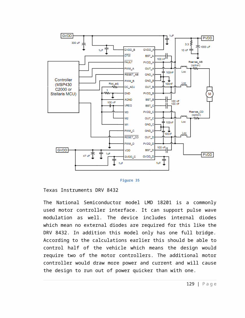
less than 25 runs of different configurations so that telemetry data may be collected and modeled. After each run, the developers may analyze data and make changes to the system as necessary, but then final acceptance testing will have to restart. The final acceptance test run will be witnessed by an outside party to ensure that test protocol is followed and can be verified by an outside party.
8. Conclusion
9. Appendices
9.1 Work Cites
9.2 Image Permission
Hello,
I am a student at the University of Central Florida Majoring in Electrical Engineering. Currently I am in senior design in a group made up of 3 other people. I would like to request permission to use some of the figures in the TDA0161 datasheet to be used in our research report document. The datasheet URL is found below.
http://www.st.com/internet/com/TECHNICAL_RESOURCES/TECHNICAL_LITERATURE/DATASHEET/CD00000119.pdf
Thank you for your time,Phong LeBSEE Undergraduate
129 | P a g e

University of Central Florida
-Apple Consent
You may use information on Apple products and services (such as data sheets, knowledge base articles, and similar materials) purposely made available by Apple for downloading from the Site, provided that you (1) not remove any proprietary notice language in all copies of such documents, (2) use such information only for your personal, non-commercial informational purpose and do not copy or post such information on any networked computer or broadcast it in any media, (3) make no modifications to any such information, and (4) not make any additional representations or warranties relating to such documents.
-Texas Instruments Consent
TI grants permission to download, reproduce, display and distribute the Materials posted on this site solely for informational and non-commercial or personal use, provided that you do not modify such Materials and provided further that you retain all copyright and proprietary notices as they appear in such Materials. TI further grants to educational institutions (specifically K-12, universities and community colleges) permission to download, reproduce, display and distribute the Materials posted on this site solely for use in the classroom, provided that such institutions identify TI as the source of the Materials and include the following credit line: "Courtesy of Texas Instruments". Unauthorized use of any of these Materials is expressly prohibited by law, and may result in civil and criminal penalties. This permission terminates if you breach any of these terms and conditions. Upon termination you agree to destroy any Materials downloaded from this site.
-How Stuff Works Consent
The materials available through the Discovery Sites are the property of Discovery or its licensors, and are protected by copyright, trademark and other intellectual property laws. You are free to display and print for your personal, non-commercial use information you receive through the Discovery Sites. But you may not otherwise reproduce any of the materials without the prior written consent of the owner.
Hello,
130 | P a g e

I am a student at the University of Central Florida Majoring in Electrical Engineering. Currently I am in senior design in a group made up of 3 other people. I would like to request permission to use some of the figures in the article “How to Prolong Lithium-based Batteries”. Below is the url to the page.
http://batteryuniversity.com/learn/article/how_to_prolong_lithium_based_batteries
Thank you for your time,Phong LeBSEE UndergraduateUniversity of Central Florida
131 | P a g e

132 | P a g e

Permission to use images Re: Motor brush replacement; use image request
6:09 PM Reply ▼ Tony Helmholdt To [email protected] Jared,
I welcome you to use any photo from my website! All I ask is that you give me a photo credit on the caption of any photos you use.
Thanks for asking first.
Hope your project turns out well.
-Tony HelmholdtOn Thu, Dec 1, 2011 at 11:41 AM, <[email protected]> wrote:To whom it may concern,
I am writing a paper for senior design and would like to the image of a brushed dc motor on your post. The paper is for school assignment and will not be republished. I would like to use the image on your article with your permission. I'd appreciate a prompt response and thank you for your time and consideration.
http://experimentalev.wordpress.com/2011/03/22/motor-brush-replacment-how-to/
Thank you,
Jerard Jose
http://en.wikipedia.org/wiki/File:H_bridge_operating.svgI, the copyright holder of this work, hereby publish it under the following licenses:
133 | P a g e

Permission is granted to copy, distribute and/or modify this document under the terms of the GNU Free Documentation License, Version 1.2 or any later version published by the Free Software Foundation; with no Invariant Sections, no Front-Cover Texts, and no Back-Cover Texts. A copy of the license is included in the section entitled GNU Free Documentation License.
This file is licensed under the Creative Commons Attribution-Share Alike 3.0 Unported license.
You are free: to share – to copy, distribute and transmit
the work to remix – to adapt the work
Under the following conditions: attribution – You must attribute the work
in the manner specified by the author or licensor (but not in any way that suggests that they endorse you or your use of the work).
share alike – If you alter, transform, or build upon this work, you may distribute the resulting work only under the same or similar license to this one.
This licensing tag was added to this file as part of the GFDL licensing update. This file is licensed under the Creative Commons Attribution-Share Alike 2.5 Generic, 2.0 Generic and 1.0 Generic license.
You are free: to share – to copy, distribute and transmit
the work to remix – to adapt the work
Under the following conditions: attribution – You must attribute the work
in the manner specified by the author or licensor (but not in any way that suggests that they endorse you or your use of the work).
share alike – If you alter, transform, or build upon this work, you may distribute the resulting work only under the same or similar license to this one.
You may select the license of your choice.
134 | P a g e
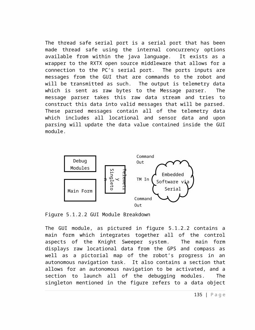
RE: Request to use image from article
1:10 PM Reply ▼ Patrick Mannion Add to contactsTo [email protected] Jerard,Sure, you can use it, but please give attribution.Ie: Image courtesy of EDN.com Thanks Patrick Mannion | Director of Content EDN | EETimes' Designlines | Test & Measurement Worldwww.edn.com | www.eetimes/design | www.tmworld.comUBM Electronics631-543-0445 | Cell: 516-474-5531Twitter: @patrick_mannionSkype: patrick_mannion2http://ubmelectronics.com/editorial-contacts/From: [email protected] [mailto:[email protected]] Sent: Thursday, December 01, 2011 12:50 PMTo: Patrick MannionSubject: Request to use image from article To whom it may concern,
I am writing a paper for a senior design project and would like permission to use an image from one of your articles. The paper is not published and is for educational purposes only. The address of the article is posted below and would request a prompt response. Thank you for your time and consideration.
http://www.edn.com/article/510206-Hardware_controlled_brushless_dc_motors_ease_the_burden_on_CPUs.php
Thank you,
Jerard Josehttp://www.piclist.com/images/www/hobby_elec/e_menu.htmThe use of the contents of my website is free. However, you are strictly forbidden to engage in any act which will lead to direct pecuniary profit from the contents of this website. For example, the sale of any information contained within these pages, or charges for access to the information. Furthermore, if you choose to quote any information found within the pages of this website, you do so at your own risk.The author accepts absolutely no responsibility for any loss or damages occurring
135 | P a g e

from the use of the information contained by this website.Please understand this before you use the information in any way.
[#HMK-491594]: Permission to use images
11/14/11 Reply ▼ (JB) RobotShop inc. Add to contactsTo [email protected] Jerard Jose,
You want to place images and description in your research paper? Will this be published online?
The problem is that we are granted rights by the copyright owners (the manufacturers) to use their images on our websites. In many cases, the descriptions are adapted from their documentation. We also have content on our website that is RobotShop's intellectual property.
So as you can see, we can not grant rights for content to which we do not have permission to grant. If it is simply for a school project (that does not include a website or web published document), then simply credit RobotShop in your document and nobody will ever know.
If you are publishing the work online then it gets complicated and we do not generally provide "carte blanche" to copy our content due to numerous complications this can create. The Digital Millennium Copyright Act and proposed legislation under the ACTA agreement might cause you problems.
Kind regards,
Jonathan
136 | P a g e
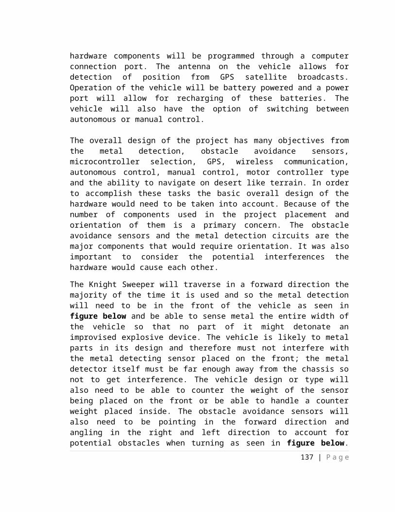
Technical Team - Équipe Technique
RobotShop inc.
Robotics at your service!®
La Robotique à votre Service!®
Web: www.robotshop.com
-----------------------------------------------------------------
Sign in at robotshop.helpserve.com to see your full support history.
Visitez robotshop.helpserve.com pour voir votre historique de support complet.
Ticket Details / Détails du ticket
===================
Ticket ID: HMK-491594
Department: Webmaster
Status: Closed
SoR
12:55 PM Reply ▼ jerard.jos [email protected] cf.edu To [email protected] whom it may concern,
I am writing a paper for a senior design project and would like permission to use an image from one of your articles. The paper is not published and is for educational purposes only. The address of the article is posted below and would request a prompt response. Thank you for your time and consideration.
http://www.societyofrobots.com/actuators_servos.shtml
Thank you,
137 | P a g e

Jerard Jose
Pulse width modulation figure.This article was published in the September 2001 issue of Embedded Systems Programming. If you wish to cite the article in your own work, you may find the following MLA-style information helpful:Barr, Michael. "Pulse Width Modulation," Embedded Systems Programming, September 2001, pp. 103-104.
Request permission to use images.
8:59 PM Reply ▼ jerard.jos [email protected] cf.edu To [email protected]
138 | P a g e

To whom it may concern,
I am writing a paper for a senior design project and would like permission to use an image from one of your articles. The paper is not published and is for educational purposes only. The address of the article is posted below and would request a prompt response. Thank you for your time and consideration.
The images in question are on the page: http://www.dprg.org/tutorials/1998-04a/
Thank you,
Jerard Jose
10.3 Code Libraries
139 | P a g e