Embed Size (px)
Citation preview
The use of TiO2-polymer composites to lower environmental impact and improve performance of waterborne paints
Andrew Trapani1, Marie Bleuzen2, Houshang Kheradmand2 and Anne Koller2
1The Dow Chemical Company, Dow Coating Materials, Valbonne, France, [email protected]
2The Dow Chemical Company, Dow Coating Materials, Valbonne, France
INTRODUCTIONThe primary white hiding pigment in high quality
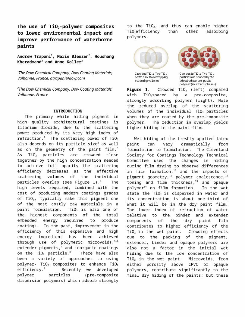
architectural coatings is titanium dioxide, due to the scattering power produced by its very high index of refraction.1 The scattering power of TiO2 also depends on its particle size2 as well as on the geometry of the paint film.3 As TiO2 particles are crowded close together by the high concentration needed to achieve full opacity the scattering efficiency decreases as the effective scattering volumes of the individual particles overlap (see Figure 1).4 The high levels required, combined with the cost of producing modern coatings grades of TiO2, typically make this pigment one of the most costly raw materials in a paint formulation. TiO2 is also one of the highest components of the total embedded energy required to produce coatings. In the past, improvement in the efficiency of this expensive and high energy ingredient has been achieved through use of polymeric microvoids,5,6 extender pigments,7 and inorganic coatings on the TiO2 particle.8 There have also been a variety of approaches to using polymer- TiO2 composites to enhance TiO2 efficiency.9 Recently we developed polymer particles (pre-composite dispersion polymers) which adsorb strongly to the TiO2, and thus can enable higher TiO2efficiency than other adsorbing polymers.
Crowded TiO2: Two TiO2particles with overlapping scattering volumes.
Composite TiO2: Two TiO2particles are spaced by the adsorbed pre-composite polymer (small red spheres).
Figure 1. Crowded TiO2 (left) compared with TiO2spaced by a pre-composite, strongly adsorbing polymer (right). Note the reduced overlap of the scattering volumes of the individual TiO2 particles when they are coated by the pre-composite polymer. The reduction in overlap yields higher hiding in the paint film.
Wet hiding of the freshly applied latex paint can vary dramatically from formulation to formulation. The Cleveland Society for Coatings Technology Technical Committee used the changes in hiding during film drying to observe differences in film formation,10 and the impacts of pigment geometry,11 polymer coalescence,12 toning and film thickness,13 and opaque polymer14 on film formation. In the wet state the TiO2 is dispersed in water and its concentration is about one-third of what it will be in the dry paint film. The lower index of refraction of water relative to the binder and extender components of the dry paint film contributes to higher efficiency of the TiO2 in the wet paint. Crowding effects due to the packing of the pigment, extender, binder and opaque polymers are also not a factor in the initial wet hiding due to the low concentration of TiO2 in the wet paint. Microvoids, from either porosity above CPVC or opaque polymers, contribute significantly to the final dry hiding of the paints; but these voids have not yet developed in the wet paint.
Wet hiding effects are important commercially as professional painters often equate the quality of the paint with its wet hiding. Initially all the latex paints which contain TiO2 drop in scattering power as they dry due to two primary effects: (A) the index of refraction rises from that of water to an average of the binder and extenders, thus reducing the contrast with TiO2 and lowering its scattering power; and (B) as the concentration of the TiO2 increases and the other particles restrict its location, the dependent scattering effects from the TiO2 crowding become significant. When the TiO2 use level in a formulation is low and a large amount of >CPVC porosity is a major source of dry hiding, the initial hiding of the wet paint can be lower than the final dry hiding of the paint. This can make it difficult for the painter to properly judge the color and hiding during the application process. In somewhat higher quality paints formulated only slightly above CPVC the initial wet and final dry hiding and color are closer together, which makes it easier to judge the final hiding and color during application. Below the CPVC the initial wet hiding is considerably higher than the dry hiding. This gives an impression of high quality during application, but this drop in hiding on drying can result in difficulty judging the final hiding and color during application.
While wet hiding is a very sensitive probe for monitoring latex film formation through the drying phases, a number of other techniques have recently been used to help elucidate further details of latex film formation15,16,17,18 and pigment distribution.19 This improved understanding of film formation has helped the coatings industry to lower VOC in formulations while delivering high performance paints. Lowering TiO2 usage via polymer- TiO2 composites continues this effort to lower the environmental impact of the coatings.
EXPERIMENTAL RESULTSInteractions of latex particles with TiO2 have helped boost
the scattering power of many paint formulations. But the efficiency of the TiO2 scattering in the formulation has varied with changes in surfactants, dispersants and thickeners. And
that scattering has sometimes varied with time due to slow equilibration of the paint. Recently we developed adsorbing latex particles which interact more robustly with the TiO2
surface, making the final hiding of the paint less dependent on the additives in the paint.
Defining the necessary Pre-composite/TiO2 Ratio. A key consideration in the formulation of the composite is the number of pre-composite particles which are needed to saturate the TiO2 surface. If the TiO2 is not saturated, then the pre-composite particle can potentially bridge between two TiO2 particles. Bridging can continue, involving other pre-composite and TiO2 particles to make very large aggregates. This pre-composite: TiO2 ratio can be thought of in several metrics such as the number ratio, weight ratio or volume ratio of adsorbing latex particles per TiO2 particle. One particularly convenient metric is the PVC of the TiO2 in the composite, so we can treat the composite formulation similarly to the way we formulate paints.
One can determine the Critical Composite Ratio (CCR), the PVC where the pre-composite saturates the TiO2 surface, by titrating TiO2 into the pre-composite. A 20 PVC, 38.7 VS Composite was prepared in a small container, adding the following materials in order with continuous good mixing:
Pre-Composite A 43.57 gDefoamer 0.10 gWater 6.77 gTiO2 Slurry Q (70% TiO2) 23.30 g
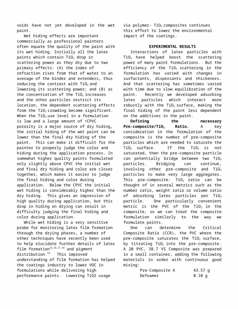
The Brookfield Viscosity (Spindle 4, 60 rpm) was determined. TiO2 was added in aliquots, with three minutes of mixing between additions. The viscosity was determined at the end of each three-minute mix. The results may be seen in Figure 2.
0500
1000150020002500300035004000450050005500600065007000
20% 25% 30% 35% 40% 45% 50% 55% 60%
TiO2 PVC
Bro
okfie
ld (c
ps)
Figure 2. Critical Composite Ratio (CCR) Titration of Pre-Composite A with TiO2 Slurry Q.
As the TiO2 concentration increases, the number of saturated composite particles increases. Since the composite particle has a larger hydrodynamic volume than the individual pre-composite and TiO2 particles which form it, the viscosity
will climb modestly. Once we approach the critical composite ratio, the viscosity increase becomes dramatic as bridging occurs between unsaturated composite particles. So the CCR for this combination of Pre-Composite A (a pre-composite polymer with a pure acrylic composition) and TiO2 Slurry Q is about 35 PVC. Typically the composite should be formulated somewhat below the CCR to minimize the possibility of grit formation.
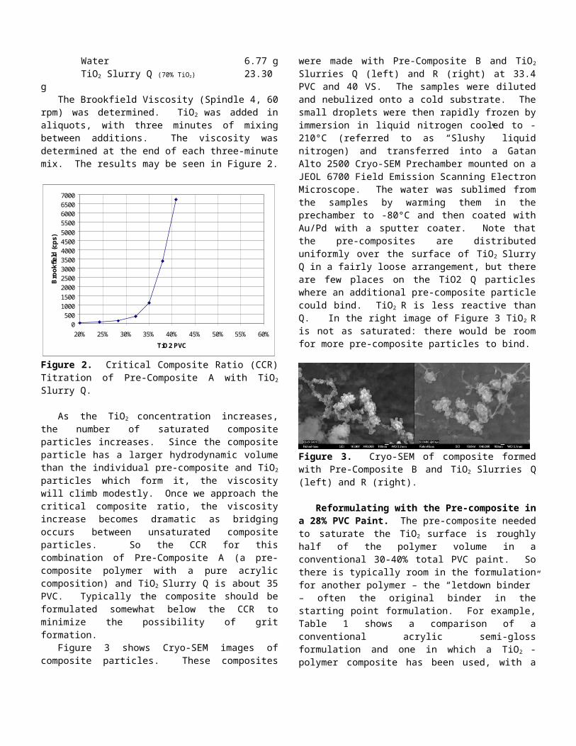
Figure 3 shows Cryo-SEM images of composite particles. These composites were made with Pre-Composite B and TiO2
Slurries Q (left) and R (right) at 33.4 PVC and 40 VS. The samples were diluted and nebulized onto a cold substrate. The small droplets were then rapidly frozen by immersion in liquid nitrogen cooled to -210°C (referred to as “Slushy” liquid nitrogen) and transferred into a Gatan Alto 2500 Cryo-SEM Prechamber mounted on a JEOL 6700 Field Emission Scanning Electron Microscope. The water was sublimed from the samples by warming them in the prechamber to -80°C and then coated with Au/Pd with a sputter coater. Note that the pre-composites are distributed uniformly over the surface of TiO2 Slurry Q in a fairly loose arrangement, but there are few places on the TiO2 Q particles where an additional pre-composite particle could bind. TiO2 R is less reactive than Q. In the right image of Figure 3 TiO2 R is not as saturated: there would be room for more pre-composite particles to bind.
Figure 3. Cryo-SEM of composite formed with Pre-Composite B and TiO2 Slurries Q (left) and R (right).
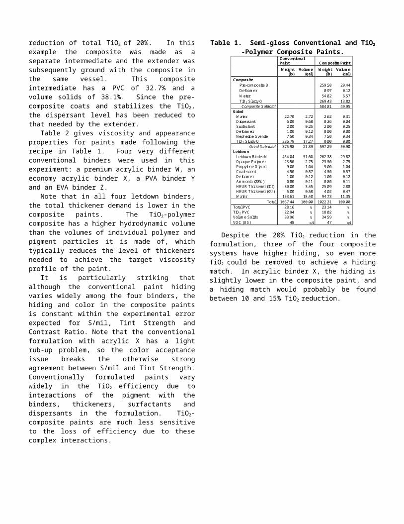
Reformulating with the Pre-composite in a 28% PVC Paint. The pre-composite needed to saturate the TiO2 surface is roughly half of the polymer volume in a conventional 30-40% total PVC paint. So there is typically room in the formulation for another polymer – the “letdown binder” – often the original binder in the starting point formulation. For example, Table 1 shows a comparison of a conventional acrylic semi-gloss formulation and one in which a TiO2 -polymer composite has been used, with a reduction of total TiO2 of 20%. In this example the composite was made as a separate intermediate and the extender was subsequently ground with the composite in the same vessel. This composite intermediate has a PVC of 32.7% and a volume solids of 38.1%. Since the pre-composite coats and stabilizes the TiO2, the dispersant level has been reduced to that needed by the extender.
Table 2 gives viscosity and appearance properties for paints made following the recipe in Table 1. Four very different conventional binders were used in this experiment: a
premium acrylic binder W, an economy acrylic binder X, a PVA binder Y and an EVA binder Z.
Note that in all four letdown binders, the total thickener demand is lower in the composite paints. The TiO2-polymer composite has a higher hydrodynamic volume than the volumes of individual polymer and pigment particles it is made of, which typically reduces the level of thickeners needed to achieve the target viscosity profile of the paint.
It is particularly striking that although the conventional paint hiding varies widely among the four binders, the hiding and color in the composite paints is constant within the experimental error expected for S/mil, Tint Strength and Contrast Ratio. Note that the conventional formulation with acrylic X has a light rub-up problem, so the color acceptance issue breaks the otherwise strong agreement between S/mil and Tint Strength. Conventionally formulated paints vary widely in the TiO2 efficiency due to interactions of the pigment with the binders, thickeners, surfactants and dispersants in the formulation. TiO2-composite paints are much less sensitive to the loss of efficiency due to these complex interactions.
Table 1. Semi-gloss Conventional and TiO2 -Polymer Composite Paints.
Conventional Paint Composite Paint
Weight
(lb) Volume
(gal) Weight
(lb) Volume
(gal) Composite Pre-composite B 259.58 29.44 Defoamer 0.97 0.12 Water 54.82 6.57 TiO2 Slurry Q 269.43 13.82
Composite Subtotal 584.81 49.95 Grind Water 22.70 2.72 2.62 0.31 Dispersant 6.00 0.68 0.36 0.04 Surfactant 2.00 0.25 2.00 0.25 Defoamer 1.00 0.12 0.00 0.00 Nepheline Syenite 7.50 0.34 7.50 0.34 TiO2 Slurry Q 336.79 17.27 0.00 0.00
Grind Sub-total 375.98 21.39 597.29 50.90 Letdown Letdown Binder W 454.04 51.60 262.38 29.82 Opaque Polymer 23.50 2.75 23.50 2.75 Propylene Glycol 9.00 1.04 9.00 1.04 Coalescent 4.50 0.57 4.50 0.57 Defoamer 1.00 0.12 1.00 0.12 Ammonia (28%) 0.80 0.11 0.80 0.11 HEUR Thickener (ICI) 30.00 3.45 25.09 2.88 HEUR Thickener (KU) 5.00 0.58 4.02 0.47 Water 153.61 18.40 94.73 11.35
Total 1057.44 100.00 1022.31 100.00 Total PVC 28.16 % 23.14 % TiO2 PVC 22.94 % 18.02 % Volume Solids 33.96 % 34.59 %
VOC (US) 48 g/l 47 g/l
Despite the 20% TiO2 reduction in the formulation, three
of the four composite systems have higher hiding, so even more TiO2 could be removed to achieve a hiding match. In acrylic binder X, the hiding is slightly lower in the composite paint, and a hiding match would probably be found between 10 and 15% TiO2 reduction.
Table 2. Semi-Gloss viscosity and appearance results (formulations in Table 1).
Paint Type
Conven-tional
Composite
Conven-tional
Composite
Conven-tional
Composite
Conven-tional
Composite
Letdown Binder
Acrylic W
Acrylic W
Acrylic X
Acrylic X
PVA Y
PVA Y
EVA Z
EVA Z
Wt (lb/100 gal) TiO2 Slurry Q 337 269 337 269 337 269 337 269 HEUR (ICI) 30 25.10 30 25.08 30 25 30 24.76
HEUR (KU) 5 4.03 5 4.12 9.5 3.97 13.5 12
Viscosity KU 104 108 84 100 82 91 90 108 KU equilib. 112 115 105 106 86 94 95 118 ICI 1.2 1.4 0.9 1.4 1.3 1.4 1.6 1.7
ICI equilib. 1 1.3 1.13 1.37 1.32 1.38 1.7 1.95
Hiding S/mil 6.92 7.07 7.39 7.02 6.42 7.13 6.50 7.01 Tint Strength 91.0% 100.0% 96.9% 100.2% 87.4% 98.9% 87.0% 100.0% Rub Up light
Contrast Ratio 0.9833 0.9864 0.9760 0.9868 0.9746 0.9866
Gloss 20° Gloss 22 32 29 35 20 32 21 30
60° Gloss 62 65 65 66 62 66 62 64
In the reformulation shown in Table 1 there is a 5 PVC drop between the conventional and the composite formulations due to the 20% reduction in the TiO2 level. That drop in PVC contributes directly to the increase in the gloss values seen in Table 2. In a more practical reformulation the total PVC and Volume Solids could be held constant by increasing the levels of opaque polymer and extender. Since the opaque polymer contributes independently to the scattering of the paint, the TiO2-polymer composite technology can be combined with the use of opaque polymer to maximize TiO2 reduction in the paint. Opaque polymer is similar in particle size to TiO2
which gives it a similar gloss potential, so it is particularly useful in maintaining the gloss level while replacing the dry volume of TiO2 removed in the reformulation. A precise match can then be achieved by balancing the opaque polymer and extender levels to fine-tune the gloss.
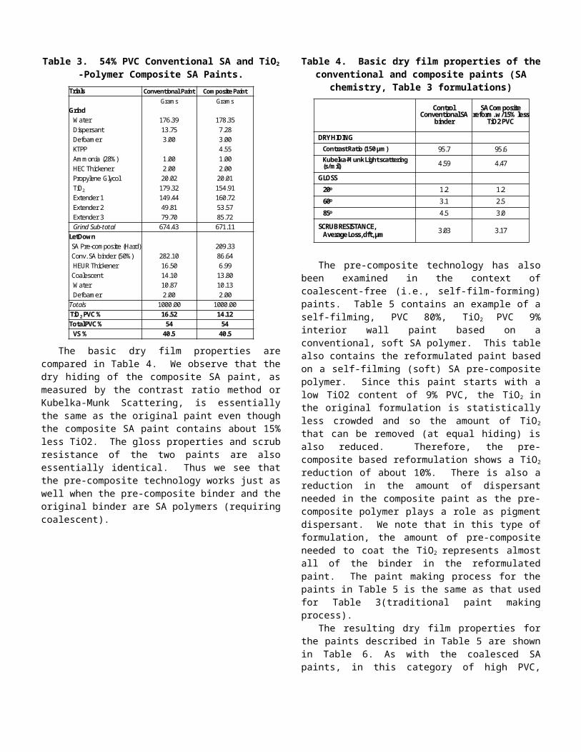
Reformulations with Styrene-acrylic Pre-composites. The previous results were obtained with a pre-composite polymer with a pure acrylic composition, however the pre-composite polymer can be made with other chemistries such as styrene-acrylic (SA) or even vinyl-acrylic. Table 3 contains a reformulation of a 54% PVC conventional paint based on traditional SA dispersion polymer requiring coalescent. The composite paint is made with a pre-composite SA polymer that also requires coalescent. At this total %PVC and %PVC of TiO2 (originally 16,5%) the pre-composite SA polymer makes up about two-thirds of the total binder in the reformulated paint (i.e, one-third of the original, conventional SA polymer remains in the reformulated paint.) The paint making process for the composite reformulation in Table 3 was a standard grinding process followed by the straight-forward introduction of the pre-composite SA polymer and the let-down binder. No special manufacturing steps were introduced.
The original paint contains 16,5% by volume (dry) and 17,9% by weight (wet) TiO2. The reformulated paint contains 14% less TiO2 by weight (wet) and 15% less TiO2 by volume
(dry). There is also less dispersant and thickener in the reformulated paint.
Table 3. 54% PVC Conventional SA and TiO2 -Polymer Composite SA Paints.
Trials Conventional Paint Composite PaintGrams Grams
GrindWater 176.39 178.35Dispersant 13.75 7.28Defoamer 3.00 3.00KTPP 4.55Ammonia (28%) 1.00 1.00HEC Thickener 2.00 2.00Propylene Glycol 20.02 20.01TiO2 179.32 154.91Extender 1 149.44 160.72Extender 2 49.81 53.57Extender 3 79.70 85.72Grind Sub-total 674.43 671.11
LetDownSA Pre-composite (Hard) 209.33Conv. SA binder (50%) 282.10 86.64HEUR Thickener 16.50 6.99Coalescent 14.10 13.80Water 10.87 10.13Defoamer 2.00 2.00
Totals 1000.00 1000.00TiO2 PVC % 16.52 14.12Total PVC % 54 54
VS % 40.5 40.5
The basic dry film properties are compared in Table 4. We observe that the dry hiding of the composite SA paint, as measured by the contrast ratio method or Kubelka-Munk Scattering, is essentially the same as the original paint even though the composite SA paint contains about 15% less TiO2. The gloss properties and scrub resistance of the two paints are also essentially identical. Thus we see that the pre-composite technology works just as well when the pre-composite binder and the original binder are SA polymers (requiring coalescent).
Table 4. Basic dry film properties of the conventional and composite paints (SA chemistry, Table 3 formulations)
ControlConventional SA
binder
SA Composite reform. w/15% less
TiO2 PVC
DRY HIDING Contrast Ratio (150 µm) 95.7 95.6Kubelka-Munk Light scattering (s/mil) 4.59 4.47
GLOSS
20o 1.2 1.2
60o 3.1 2.5
85o 4.5 3.0
SCRUB RESISTANCE,Average Loss, dft, µm 3.03 3.17
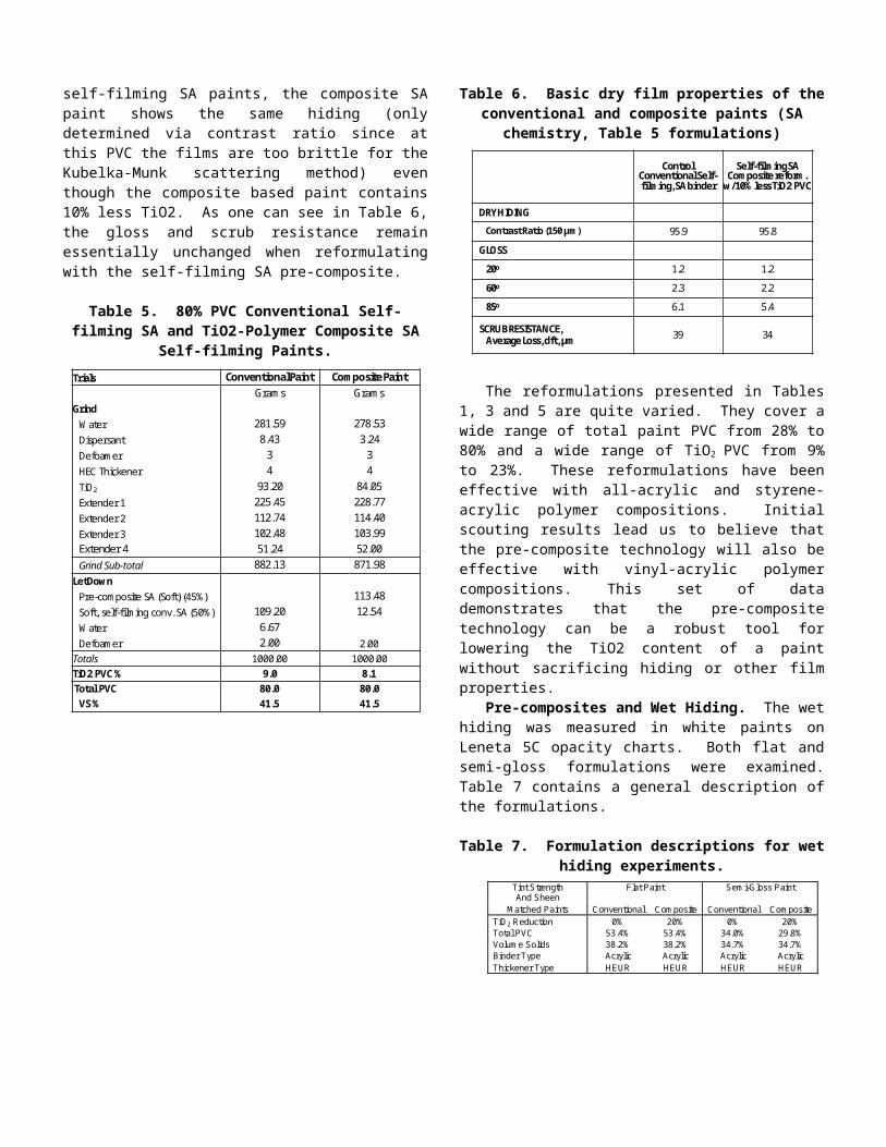
The pre-composite technology has also been examined in the context of coalescent-free (i.e., self-film-forming) paints. Table 5 contains an example of a self-filming, PVC 80%, TiO2
PVC 9% interior wall paint based on a conventional, soft SA polymer. This table also contains the reformulated paint based on a self-filming (soft) SA pre-composite polymer. Since this paint starts with a low TiO2 content of 9% PVC, the TiO2 in the original formulation is statistically less crowded and so the amount of TiO2 that can be removed (at equal hiding) is also reduced. Therefore, the pre-composite based reformulation shows a TiO2 reduction of about 10%. There is also a reduction in the amount of dispersant needed in the composite paint as the pre-composite polymer plays a role as pigment dispersant. We note that in this type of formulation, the amount of pre-composite needed to coat the TiO2 represents almost all of the binder in the reformulated paint. The paint making process for the paints in Table 5 is the same as that used for Table 3(traditional paint making process).
The resulting dry film properties for the paints described in Table 5 are shown in Table 6. As with the coalesced SA paints, in this category of high PVC, self-filming SA paints, the composite SA paint shows the same hiding (only determined via contrast ratio since at this PVC the films are too brittle for the Kubelka-Munk scattering method) even though the composite based paint contains 10% less TiO2. As one can see in Table 6, the gloss and scrub resistance remain essentially unchanged when reformulating with the self-filming SA pre-composite.
Table 5. 80% PVC Conventional Self-filming SA and TiO2-Polymer Composite SA Self-filming Paints.
Trials Conventional Paint Composite PaintGrams Grams
GrindWater 281.59 278.53Dispersant 8.43 3.24Defoamer 3 3HEC Thickener 4 4TiO2 93.20 84.05Extender 1 225.45 228.77Extender 2 112.74 114.40Extender 3 102.48 103.99Extender 4 51.24 52.00Grind Sub-total 882.13 871.98
LetDownPre-composite SA (Soft) (45%) 113.48Soft, self-filming conv. SA (50%) 109.20 12.54Water 6.67Defoamer 2.00 2.00
Totals 1000.00 1000.00TiO2 PVC % 9.0 8.1Total PVC 80.0 80.0VS % 41.5 41.5
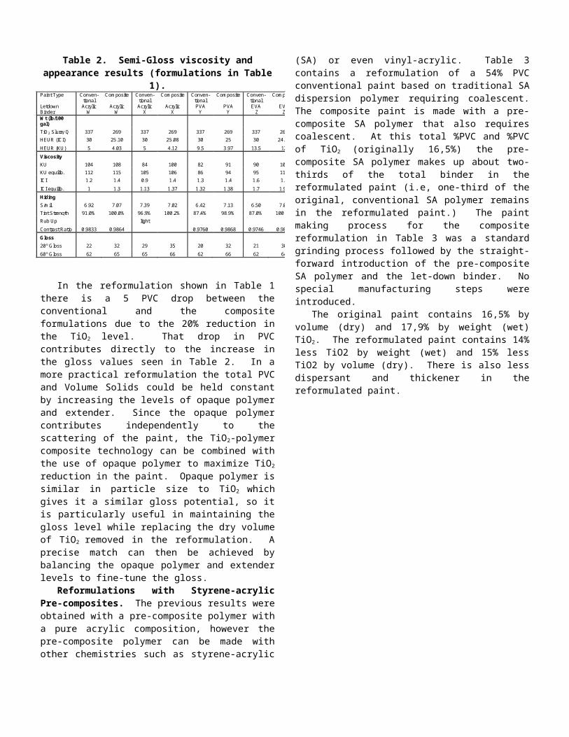
Table 6. Basic dry film properties of the conventional and composite paints (SA chemistry, Table 5 formulations)
ControlConventional Self-filming, SA binder
Self-filming SA Composite reform.
w/10% less TiO2 PVC
DRY HIDING
Contrast Ratio (150 µm) 95.9 95.8
GLOSS
20o 1.2 1.2
60o 2.3 2.2
85o 6.1 5.4
SCRUB RESISTANCE,Average Loss, dft, µm 39 34
The reformulations presented in Tables 1, 3 and 5 are quite varied. They cover a wide range of total paint PVC from 28% to 80% and a wide range of TiO2 PVC from 9% to 23%. These reformulations have been effective with all-acrylic and styrene-acrylic polymer compositions. Initial scouting results lead us to believe that the pre-composite technology will also be effective with vinyl-acrylic polymer compositions. This set of data demonstrates that the pre-composite technology can be a robust tool for lowering the TiO2 content of a paint without sacrificing hiding or other film properties.
Pre-composites and Wet Hiding. The wet hiding was measured in white paints on Leneta 5C opacity charts. Both flat and semi-gloss formulations were examined. Table 7 contains a general description of the formulations.
Table 7. Formulation descriptions for wet hiding experiments.
Tint Strength And Sheen
Flat Paint
Semi-Gloss Paint
Matched Paints Conventional Composite Conventional Composite TiO2 Reduction 0% 20% 0% 20% Total PVC 53.4% 53.4% 34.0% 29.8% Volume Solids 38.2% 38.2% 34.7% 34.7% Binder Type Acrylic Acrylic Acrylic Acrylic Thickener Type HEUR HEUR HEUR HEUR
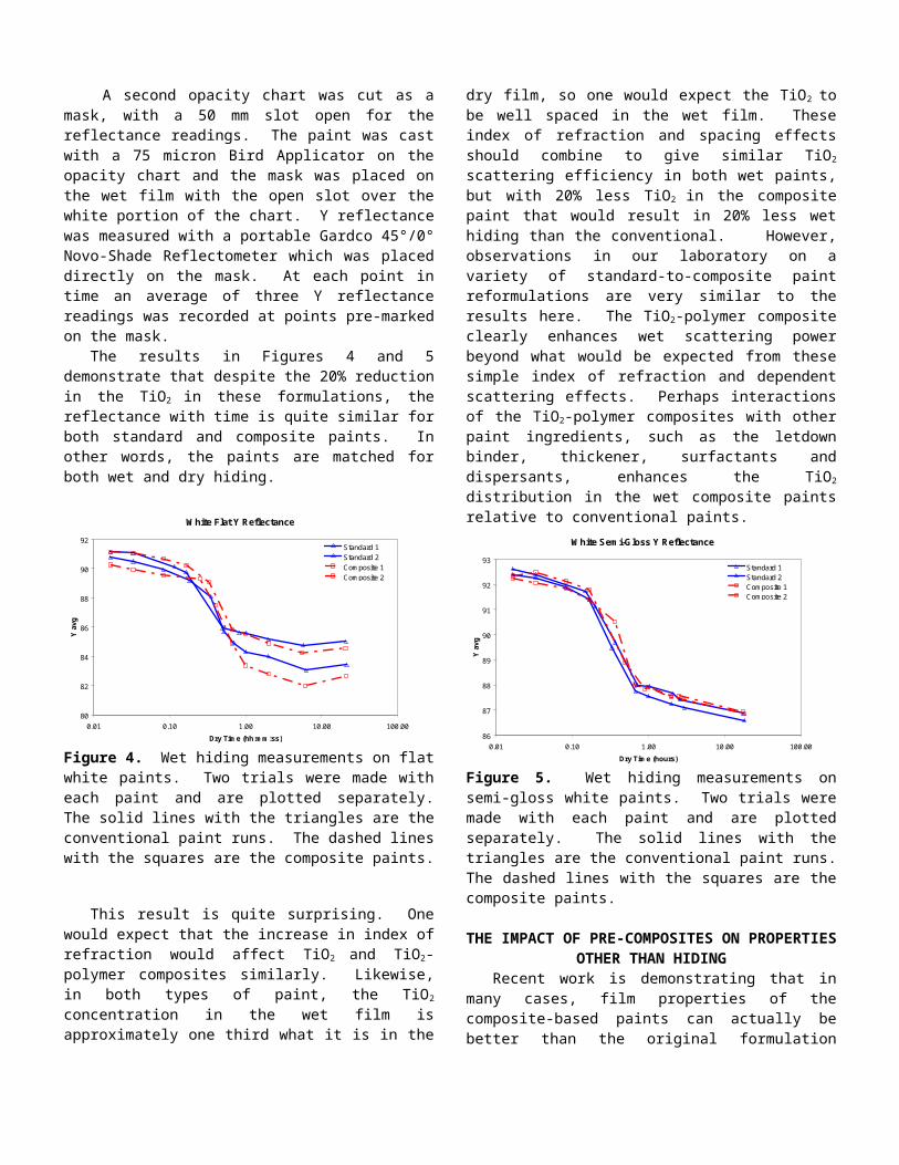
A second opacity chart was cut as a mask, with a 50 mm slot open for the reflectance readings. The paint was cast with a 75 micron Bird Applicator on the opacity chart and the mask was placed on the wet film with the open slot over the white portion of the chart. Y reflectance was measured with a portable Gardco 45°/0° Novo-Shade Reflectometer which was placed directly on the mask. At each point in time an average of three Y reflectance readings was recorded at points pre-marked on the mask.
The results in Figures 4 and 5 demonstrate that despite the 20% reduction in the TiO2 in these formulations, the reflectance with time is quite similar for both standard and composite paints. In other words, the paints are matched for both wet and dry hiding.
White Flat Y Reflectance
80
82
84
86
88
90
92
0.01 0.10 1.00 10.00 100.00
Dry Time (hh:mm:ss)
Y av
g
Standard 1Standard 2Composite 1Composite 2
Figure 4. Wet hiding measurements on flat white paints. Two trials were made with each paint and are plotted separately. The solid lines with the triangles are the conventional paint runs. The dashed lines with the squares are the composite paints.
This result is quite surprising. One would expect that the increase in index of refraction would affect TiO2 and TiO2-polymer composites similarly. Likewise, in both types of paint, the TiO2 concentration in the wet film is approximately one third what it is in the dry film, so one would expect the TiO2 to be well spaced in the wet film. These index of refraction and spacing effects should combine to give similar TiO2 scattering efficiency in both wet paints, but with 20% less TiO2 in the composite paint that would result in 20% less wet hiding than the conventional. However, observations in our laboratory on a variety of standard-to-composite paint reformulations are very similar to the results here. The TiO2-polymer composite clearly enhances wet scattering power beyond what would be expected from these simple index of refraction and dependent scattering effects. Perhaps interactions of the TiO2-polymer composites with other paint ingredients, such as the letdown binder, thickener, surfactants and dispersants, enhances the TiO2 distribution in the wet composite paints relative to conventional paints.
White Semi-Gloss Y Reflectance
86
87
88
89
90
91
92
93
0.01 0.10 1.00 10.00 100.00
Dry Time (hours)
Y av
g
Standard 1Standard 2Composite 1Composite 2
Figure 5. Wet hiding measurements on semi-gloss white paints. Two trials were made with each paint and are plotted separately. The solid lines with the triangles are the
conventional paint runs. The dashed lines with the squares are the composite paints.
THE IMPACT OF PRE-COMPOSITES ON PROPERTIES OTHER THAN HIDING
Recent work is demonstrating that in many cases, film properties of the composite-based paints can actually be better than the original formulation because the composite particles allow for the formation of a more homogenous, tighter paint film with fewer defects (see Figure 6).
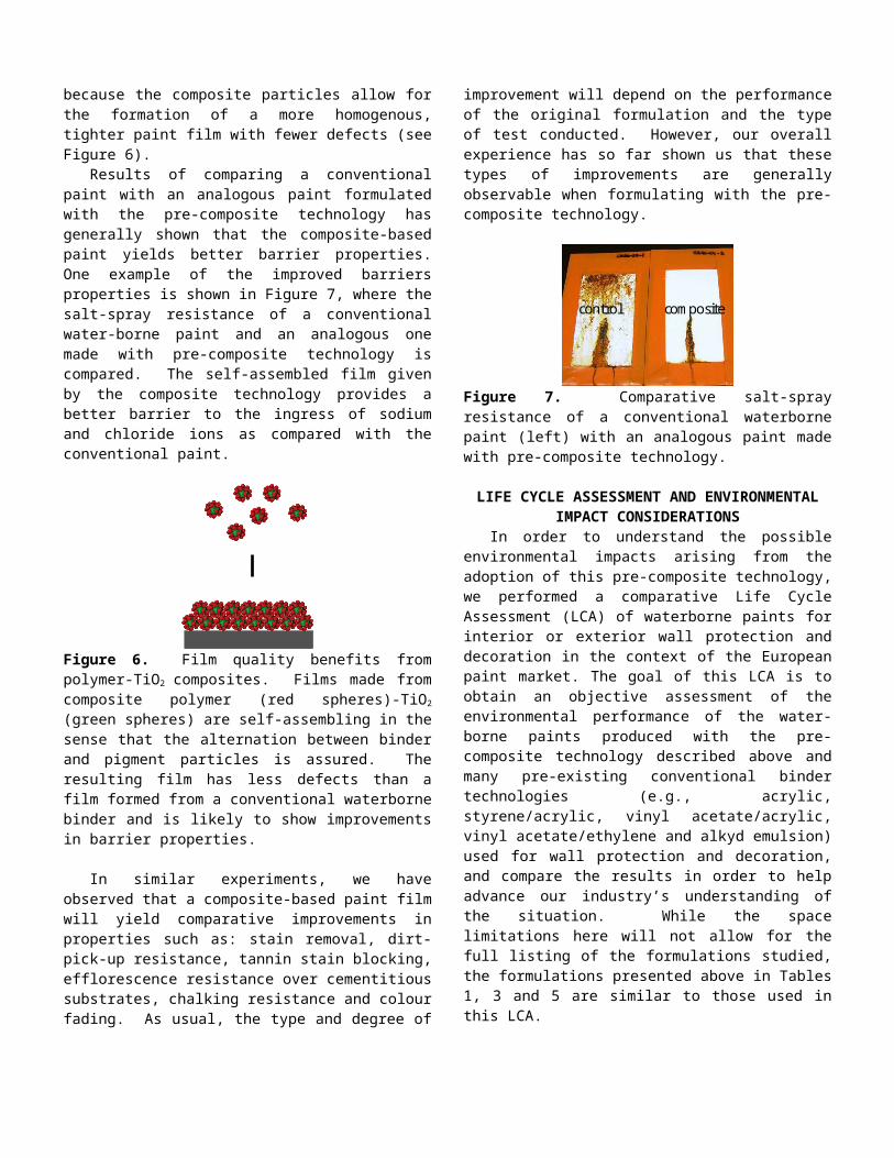
Results of comparing a conventional paint with an analogous paint formulated with the pre-composite technology has generally shown that the composite-based paint yields better barrier properties. One example of the improved barriers properties is shown in Figure 7, where the salt-spray resistance of a conventional water-borne paint and an analogous one made with pre-composite technology is compared. The self-assembled film given by the composite technology provides a better barrier to the ingress of sodium and chloride ions as compared with the conventional paint.
Figure 6. Film quality benefits from polymer-TiO2 composites. Films made from composite polymer (red spheres)-TiO2 (green spheres) are self-assembling in the sense that the alternation between binder and pigment particles is assured. The resulting film has less defects than a film formed from a conventional waterborne binder and is likely to show improvements in barrier properties.
In similar experiments, we have observed that a composite-based paint film will yield comparative improvements in properties such as: stain removal, dirt-pick-up resistance, tannin stain blocking, efflorescence resistance over cementitious substrates, chalking resistance and colour fading. As usual, the type and degree of improvement will depend on the performance of the original formulation and the type of test conducted. However, our overall experience has so far shown us that these types of improvements are generallyobservable when formulating with the pre-composite technology.
control composite
Figure 7. Comparative salt-spray resistance of a conventional waterborne paint (left) with an analogous paint made with pre-composite technology.
LIFE CYCLE ASSESSMENT AND ENVIRONMENTAL IMPACT CONSIDERATIONS
In order to understand the possible environmental impacts arising from the adoption of this pre-composite technology, we performed a comparative Life Cycle Assessment (LCA) of waterborne paints for interior or exterior wall protection and decoration in the context of the European paint market. The goal of this LCA is to obtain an objective assessment of the environmental performance of the water-borne paints produced with the pre-composite technology described above and many pre-existing conventional binder technologies (e.g., acrylic, styrene/acrylic, vinyl acetate/acrylic, vinyl acetate/ethylene and alkyd emulsion) used for wall protection and decoration, and compare the results in order to help advance our industry’s understanding of the situation. While the space limitations here will not allow for the full listing of the formulations studied, the formulations presented above in Tables 1, 3 and 5 are similar to those used in this LCA.
The LCA is performed in compliance with the requirements of International Standards (ISO 14040 and ISO 14044). A third party review and peer reviews have been performed by LCA and industry experts to provide independent opinions on this study. Several waterborne paint formulations reflecting typical PVCs are assessed in this LCA. Life cycle stages (system boundary) considered are Production, Application, Maintenance and End-of-life, for all materials. We have selected the following life-cycle inventory indicators and aggregated environmental impact categories to assess the environmental performance of the waterborne paints: primary energy consumption, total water consumption, total solid waste production, wastewater Chemical Oxygen Demand (COD), atmospheric (non-methane) Volatile Organic Carbon (NMVOC) emissions, depletion of abiotic resources, increase of the greenhouse gas effect (GHG), acidification potential, human toxicity and eutrophication potential.
The functional unit used in this study is defined as: To cover 1 m2 of wall surface for 20 years (based on standard quality criteria for the paint). Depending on paint density and durability data/assumptions, the above functional unit can be translated into total consumption of 0.34 to 0.71 kg of the studied water-borne paint formulations as top-coat (2 to 4 applications). All results and conclusions of this LCA are referring to this functional unit, unless specified otherwise.
The data used in this LCA is collected from various sources, including primarily emulsion/dispersion polymer production data collected directly from Dow factories, academic LCA publications, regional, national or sectoral standards and interviews with research institutes and paint manufacturers. When direct data is not available, assumptions have been made according to discussions with industry experts and then validated with paint manufacturers. The data and assumptions are used to build life cycle models for waterborne paints in PriceWaterhouseCoopers’ TEAM™ LCA software.20 Life Cycle Inventories (LCI) for all materials are then generated for result interpretation and analysis.
During the defined life cycle, production stages for waterborne paints (Raw materials, Emulsion/dispersion and Paint) contribute the most environmental impact. For the production of 1kg of waterborne paint, the embedded impact of raw materials contributes the most environmental impact and other production processes contribute only a small portion. Going further into the details reveals that in waterborne white paints, most of the embedded environmental impacts can be traced back to either the binder (dispersion polymer) or the pigment (TiO2), with the pigment being the overall largest contributor in most cases (contribution of the pigment is often about twice that of the binder).
Pre-composite
Ref: Pre-composite = 100
Pre-composite
Figure 8. LCA results for the functional unit for interior wall paints at 70% total PVC. Pre-composite technology (green) is taken at the reference at 100 and all other binder technologies are represented relative to this reference. The pre-composite technology yields the lowest impact for all impact categories compared to the other binder technologies.
Figure 8 shows the comparative results for the functional unit defined above for white interior wall paints at 70% overall PVC. The pre-composite technology (with all-acrylic polymer composition) yields the lowest impact for all the categories compared to the other binder technologies. This result is mainly driven by the reduction in TiO2 made possible by the pre-composite technology but the improved durability of the composite-based paint also plays a role in lowering the overall impact of the paint.
Figure 9 shows the comparative results for the functional unit defined above for white exterior masonry paints at 50% overall PVC. As with the case examined in Figure 4, the pre-composite technology (with all-acrylic polymer composition) yields the lowest impact for all the categories compared to the other binder technologies. Once again the drivers for the decrease in impact is driven by the TiO2 reduction (-15% by weight compared to the conventional formulation) and performance improvements.
Ref: Pre-composite = 100
Pre-composite
Figure 9. LCA results for the functional unit for exterior masonry paints at 50% total PVC. Pre-composite technology (green) is taken at the reference at 100 and all other binder technologies are represented relative to this reference. The pre-composite technology yields the lowest impact for all impact categories compared to the other binder technologies.
The results shown in Figures 8 and 9 can be extended to all of the paint formulation scenarios studied in this LCA. In general, the paint based on the pre-composite technology yielded the lowest impacts across the categories.
CONCLUSIONSThe stronger interactions of pre-composite particles with
TiO2 give higher and more consistent hiding efficiency than less strongly interacting polymer particles. By creating robust TiO2-polymer composites, formulators can lower the energy and raw materials cost of delivering both wet and dry hiding in their paints while still delivering premium performance to other properties such as stain and scrub resistance. The combination of the pre-composite and the letdown binder gives additional flexibility to the formulators in optimizing the quality and environmental impact of their paints.
The pre-composite technology can be a formulation tool to more efficiently use a relatively costly raw material like TiO2. In this way, the paint formulator can possibly reduce costs while at the same time the resulting paint might be higher performing in terms of film properties and environmental profile (as measured via an LCA methodology).
ACKNOWLEDGEMENTSThe authors thank the following for their contributions
and collaboration relative to the work presented in this paper: Dan Bors, Ward Brown, Susan Fitzwater, John Hook, Odile Quet, John Reffner, Łukasz Zukowski (all of The Dow Chemical Company).
1REFERENCES.Braun, J.H., Baidins, A., Marganski, R.E., “TiO2 pigment technology: a review,” Progress in Organic Coatings, 20, No.
2, 105-138 (1992).2 . Ross, W.D., “Theoretical Computation of Light Scattering Power,” Journal of Paint Technology, 43, No. 563, 50-
66 (1971).3 . Steig, F.B., “The Effect of Extenders on the Hiding Power of Titanium Pigments,” Official Digest, 31, No. 408,
52-64 (1959).4 . Fitzwater, S, and Hook, J.W., “Dependent Scattering Theory: A New Approach to Predicting Scattering in
Paints,” Journal of Coatings Technology, 57, No. 721, 39-47 (1985).5 . Fasano, D.M, “Use of Small Polymeric Microvoids in Formulating High PVC Paints,” Journal of Coatings
Technology, 59, No. 752, 109-116 (1987).6 . McDonald, C.J., Devon, M.J., “Hollow latex particles: synthesis and applications,” Advances in Colloid and
Interface Science, 99, No. 3, 181-213 (2002).7 .Steig, F.B., “The Dilution Efficiency of Extenders,” Journal of Coatings Technology, 53, No. 680, 75-79 (1981).8 .Steig, F.B., “Avoiding Excessive Titanium Costs,” Journal of Coatings Technology, 53, No. 682, 65-69 (1981).9 .Herk, A.M. “Encapsulation of Inorganic Particles,” Polymeric Dispersions: Principles and Applications, 435-450
(1997).10 .Anwari, F., Carlozzo, B.J., Chokshi, K., Chosa, M., DiLorenzo, M., Knauss, C.J., McCarthy, J., Rozick, P., Slifko,
P.M., and Weaver, J.C., “Changes in Hiding During Latex Film Formation,” Journal of Coatings Technology, 62, No. 752, 43-54 (1990).
11 .Anwari, F., Carlozzo, B.J., Chokshi, K., Chosa, M., DiLorenzo, M., Heble, M., Knauss, C.J., McCarthy, J., Rozick, P., Slifko, P.M., Stipkovich, W., Weaver, J.C., and Wolfe, M., “Changes in Hiding During Latex Film Formation: Part II. Particle Size and Pigment Packing Effects,” Journal of Coatings Technology, 63, No. 802, 35-46 (1991).
12 .Anwari, F., Carlozzo, B.J., Chokshi, K., Chosa, M., DiLorenzo, M., Heble, M., Knauss, C.J., McCarthy, J., Rozick, P., Slifko, P.M., Stipkovich, W., Weaver, J.C., and Wolfe, M., “Changes in Hiding During Latex Film Formation: Part III. Effect of Coalescent Level and Latex Properties,” Journal of Coatings Technology, 64, No. 804, 79-86 (1992).
13 .Anwari, F., Carlozzo, B.J., Chokshi, K., Chosa, M., DiLorenzo, M., Heble, M., Knauss, C.J., McCarthy, J., Rozick, P., Slifko, P.M., Stipkovich, W., Weaver, J.C., and Wolfe, M., “Changes in Hiding During Latex Film Formation: Part III. Effect of Coalescent Level and Latex Properties,” Journal of Coatings Technology, 64, No. 804, 79-86 (1992).
14 .Anwari F., Carlozzo, B.J., Chokshi, K., DiLorenzo, M., Heble, M., Knauss, C.J., McCarthy, J., Patterson, R., Rozick, P., Slifko, P.M., Stipkovich, W., Weaver, J.C., and Wolfe, M., “Changes in Hiding During Latex Film Formation: Part V. Effect of Opaque Polymer,” Journal of Coatings Technology, 65, No. 821, 39-48 (1993).
15 .Sperry, P.R., Snyder, B.S., O’Dowd, M.L., and Lesko, P.M., “Role of Water in Particle Deformation and Compaction in Latex Film Formation,” Langmuir, 1994, 10, 2619-2628 (1994).
16 .Winnik, M.A., ‘‘Latex Film Formation,’’ Current Opinion in Colloid and Interface Science., 2, 192–199 (1997).17 .Provder, T., and Urban, M., Editors, Film Formation in Coatings: Mechanisms, Properties, and Morphology,
Oxford University Press, Washington, DC (2001).18 .Ma, Y., Davis, H.T., and Scriven, L.E., “Microstructure development in drying latex coatings,” Progress in
Organic Coatings, 52 (1), 46-62 (2005).19 .Ingham, B., Dickie, S., Nanjo, H., and Toney, M.F., “In situ USAXS measurements of titania colloidal paint films
during the drying process,” Journal of Colloid and Interface Science, 336, 612-615 (2009).20 .Information on the TEAM™ software and methodology is available at https://ecobilan.pwc.fr/uk_tools.php
(accessed May 2012).