Embed Size (px)
Citation preview
Offaly Local Authorities
Requirementsfor
Public Lighting Worksfor
Residential Developments
Aras An Chontae, Charleville Rd, Tullamore, Co OffalyTel: (057) 9346800/Fax: (057) 9346868/ www.offalycoco.ie
Contents
Section:
1. General Information
2. Public Lighting Requirements
3. Lighting Column and Bracket
4. Fitting Out of Column
5. Control
6. Public lighting Customer Service Pillar
7. Fitting Out of Customer Service Pillar
8. Cable and Ducting
9. Earthing
10. Main Protective Conductor
11. Supply Connections and Main Supply Point
12. Column Installation
13. Safety
14. Standards
15. Drawings
16. Sample List of Approved Suppliers
1.0. General Information
1.1 Scope: This guide sets down specified standards and technical specifications which shall be com-plied with by developers undertaking public or private developments to assist them in pro-viding adequate lighting to the Irish Standard for road lighting, I.S. EN 13201-2:2003 while observing ETCI wiring regulations and ESB Networks Distribution System interface requirements. This document sets out the general public lighting requirements for all such developments. Where special circumstances occur, that require deviation from this document, these shall be clearly agreed in writing with the Local Authority in advance of any work commencing on site.
1.2 Public Lighting Design and Planning Permission: A public lighting design must be carried out and submitted with the plans of the development to the Planning Section of the Local Authority. All works must be carried out in accordance with the subsequent planning permission conditions, and any revised drawings and consequent lighting design must be submitted and agreed with the local Authority.
1.3 Consultation: The developer shall consult with the Local Authority at the earliest opportunity before beginning development works on site. The developer shall not make any alterations to the public lighting design submitted at the planning stage, and so agreed, without the written permission of the Local Authority. If danger exists on the development site due to overhead electrical lines the developer shall consult with ESB Networks, preferably at the planning stage.
1.4 Connection and Commissioning of the public lighting installation: On completion of each section of the public lighting installation the developer shall apply to ESB Networks for connection of supply with –
The relevant Completion Certificate A location map on which the relevant lanterns/columns, and supply Customer Service Pillars
are clearly marked. All connections and electrical commissioning and associated costs shall be the responsibility of the developer.
1.5 Taking in-Charge: On satisfactory completion of the development the Local Authority may, if requested, take in-charge the public lighting installation. The taking in charge will be as part of an application to take roads and services in charge. The Local Authority will not take public lighting only in charge. Following inspection by the Authority and the carrying out of any required tests, the developer shall be issued with a written notification of any works which the Authority considers necessary to bring the development up to the required standard. In relation to the public lighting all such tests and work shall be carried out by the developer’s electrical contractor and all costs shall be their responsibility.
1.6 Public Lighting Operating Costs (Energy and Maintenance): Public lighting qualifies for unmetered supply where the total load per connection point is less than 2kva (2kw). Where the total load per connection point exceeds 2kva (2kw) the installation will require metering and a special metering pillar shall be installed to accommodate the ESB meter and gear. The Local Authority will only accept responsibility for the energy and maintenance costs of public lighting, where taking in-charge has been agreed, and where the developer has satisfied the Authority that the public lighting has been installed to the required standards.
2.0. Public Lighting Requirements
2.1. Public Lighting may not be appropriate in all locations. However, if it is to be provided it shall be of high quality.
2.2. All public lighting installation for residential developments shall be designed to the requirements of IS EN 13201-2, IS EN 13201-3, and IS EN 13201-4, and BS 5489-1: 2013 which contains guidance and recommendations that are intended to support EN 13201 and assist designers of lighting systems in using the standard.
2.3. For aesthetic reasons the height of the lighting column shall not generally exceed that of nearby buildings. In a typical residential development of two storey houses the height of the column shall be 6m. In certain circumstances a 5m column may be permitted. At these low mounting heights, post mounted lanterns without brackets can be aesthetically advantageous. However, if a bracket is to be used, a straight rising bracket with a 50 tilt shall be used (see 3.7).
2.4. The design of the lighting shall be carried out by a competent person with experience in the design of public lighting installations.
2.5. Lighting shall be planned as an integral part of the street layout, taking account of the location of planting to avoid the resultant blocking affect of high level planting such as trees.
2.6. Where a road is to be lit, care shall be taken not to over-light as this can create unnecessary light pollution, light trespass, and increased energy consumption. Light above the horizontal shall be minimised by restriction of the Upward Light Output Ratio (ULOR).
2.7. The lighting installation shall consist of high performance LED lanterns which shall be suitable for post mounting directly on a public lighting column with a spigot size of 76mm or side-entry mounting on an outreach bracket with a spigot size of 60mm.
2.8. The lantern shall be designed and constructed to operate in Irish climatic conditions for a minimum of period of 15 years.
2.9. The colour rendition (Ra) and colour temperature (K) of the LED light source shall be an important consideration. The minimum acceptable Ra shall be ≥ 60 (White Light), while the colour temperature of the LED source shall be (Cool White). An option for a colour temperature of Neutral White shall also be available.
2.10. The LED lantern housing shall be manufactured from Aluminium and be capable of accommodating a three pin NEMA socket for a standard photocell or alternatively a miniature photocell.
2.11. The lantern shall be protected against the ingress of dust and water and shall have an IP66 rating as a minimum for the optical and driver compartments.
2.12. The lighting installations shall be controlled by solid state Photo Electric Cells which a have a dusk to dawn switching ratio of 70/70 lux (on/off). This equates with 4,150 annual operational hours. This switching ratio may be reduced in the future and will be advised.
2.13. A lighting installation may not require to be constant during the hours of darkness. Where possible a dusk to mid-night regime shall be considered providing for reduced annual hours of usage (1,571 hrs). A special dusk to mid-night PEC can easily facilitate this option.
2.14. A fixed terminal block with clearly identified phase, neutral, and earth connections shall be provided and provision shall be made to clamp all incoming cables.
2.15. The lantern and components shall conform to the required standards and be suitable for use on a 230V nominal supply voltage (-10%/+6%) on a 50 cycle AC circuit.
2.16. Where the design parameters vary during the hours of darkness, i.e. reduced traffic flow and use by pedestrians, consideration shall be given to the design of variable lighting, and thereby minimise energy consumption and light pollution, at times when lower lighting levels may be adequate.
3.0. Lighting Column and Bracket (where applicable)
3.1 The lighting column manufacturer shall be registered with and certified by the National Standards Authority of Ireland, for the design and manufacture of lighting columns and brackets, under their quality assurance schedule to IS EN ISO: 9001: 2000.
3.2. Lighting columns shall be of tapered octagonal construction with a minimum wall thickness of 3mm and shall comply with the requirements of BS 5649 or EN40. In certain circumstances, and with prior approval, a tubular column with a flush door may be accept-able. Brackets (where applicable) shall be of tubular construction with a minimum wall thickness of 4mm (see 3.7). Columns and brackets should be protected against corrosion by hot-dip galvanising, in accordance with IS EN ISO 1461.
3.3. Mill test certificates may be required for the column and bracket steel sections.
3.4. Octagonal Columns shall be 6 metres above ground with a 1 metre long root (7m total length), of folded steel, gradually tapered at a constant rate from the base and terminating with a dimension of 68mm across flats at the top (Drawing No: PL/504/05).
3.5. The base shall be fitted with a cable entry opening of 180 x 60mm, with the top of the opening 700mm from the base end. A base compartment shall be provided in the shaft with a welded in frame for a recessed fitting door (Drawing No: PL/504/06). The internal diameter of the compartment shall be not less than 120mm and the bottom of the compartment shall be 1300mm above ground level.
The door shall be vandal resistant and weatherproof to IP 33 with two recessed locking mechanisms requiring a female triangular key of 10mm side. The dimensions of the door shall be 385mm x 90mm (frame size 400mm x 108mm) and all doors must be interchangeable.
3.6. An earthing connection shall be provided within the base compartment of the column and the fastening screw for this connection should be of stainless steel.
3.7. The bracket (where applicable) shall be of the single arm type in 60mm tube with a 4mm wall thickness and made from steel which is equal to or better than BS EN 10025 (1993) S 275 JO. It shall be inclined 50 above the horizontal and constructed to permit clear movement of cable through bracket and column (Drawing No: PL/504/07).
3.8. The column and bracket combination shall be required to carry a side-entry lantern of max weight 11.5kg and a max wind area of 0.057m2 The optical centre of the lantern shall be considered to be 1,200mm from the shaft axis where side-entry mounted on the 700mm bracket, and 500mm from the shaft axis where post mounted. However, the column shall be designed to carry a twin bracket with lanterns of similar max weight and max wind area.
3.9. The lighting column shall be designed in accordance with the following standard:
EN 40-3-1: 2000: Lighting Columns – Design and Verification—Specification for Characteristic Loads.
3.10. Detailed wind loading calculations shall be carried out in accordance with the following standard:
Eurocode 1: Part 2.4 (DD ENV 1991-2-4) 1997. When designing to this standard a reference wind velocity of 30m/s (10 minute storm) and a Terrain Category of 2 shall be used.
3.11. Calculations using the 60 minute storm or the 3 second gust wind speed will not be acceptable.
3.12. The column and bracket shall carry a permanent identification mark, indicating the manufacturer and year of manufacture. Both identification marks shall be clearly visible fol-lowing galvanising.

4.0. Fitting Out of Column
4.1. A detachable hardwood baseboard, measuring 400x80x20mm shall be fitted in the base compartment of the column. The clearance between the baseboard and the inside face of the door, when secured, shall be not less than 100mm.
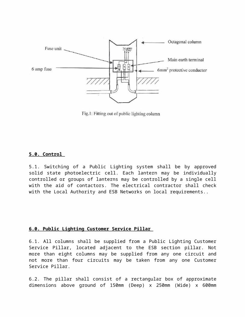
4.2. Each lantern shall be individually protected with a suitable fuse unit in the column base.
4.3. Neutral blocks, or looping-in blocks, shall be of an approved grooved bore 63A type, fully insulated and solidly mounted on the baseboard.
4.4. Columns shall be wired with a minimum 2.5mm2 PVC/PVC stranded copper cable. The internal electrical arrangement shall be as shown in Fig. 1
5.0. Control
5.1. Switching of a Public Lighting system shall be by approved solid state photoelectric cell. Each lantern may be individually controlled or groups of lanterns may be controlled by a single cell with the aid of contactors. The electrical contractor shall check with the Local Authority and ESB Networks on local requirements..
6.0. Public Lighting Customer Service Pillar
6.1. All columns shall be supplied from a Public Lighting Customer Service Pillar, located adjacent to the ESB section pillar. Not more than eight columns may be supplied from any one circuit and not more than four circuits may be taken from any one Customer Service Pillar.
6.2. The pillar shall consist of a rectangular box of approximate dimensions above ground of 150mm (Deep) x 250mm (Wide) x 600mm (High). The root section shall be 320mm long and turned out at the bottom for a distance of 50mm.
6.3. The pillar shall be fitted with a recessed, lift-out, door with a weather strip all round. The door shall be fixed with an M8 triangular headed locking screw at the top onto a suitably tapped fixing plate and secured at the bottom by a fixed catch onto the weather strip.
6.4. The door shall be equipped with a suitable unobtrusive finger grip to facilitate easy removal of the door.
6.5. The minimum ope size shall be 220mm wide x 510mm high
6.6. The pillar shell, door, and extension plates shall be of 3mm thick mild steel. The pillar, when fabricated, shall be suitable for free standing or recessing into a wall.
6.7. A hardwood baseboard, treated with a wood preservative, shall be fitted in each pillar which shall be easily removable.
6.8. A main earth terminal shall also be provided with an insulated earth fly lead to the door.
6.9. After fabrication the pillar shall be hot dipped galvanized both inside and outside in accordance with BS EN ISO 1461.
6.10. The pillar shall have a smooth exterior finish and be free of all sharp and rough edges, both outside and inside.
7.0. Fitting Out of Public Lighting Customer Service Pillar
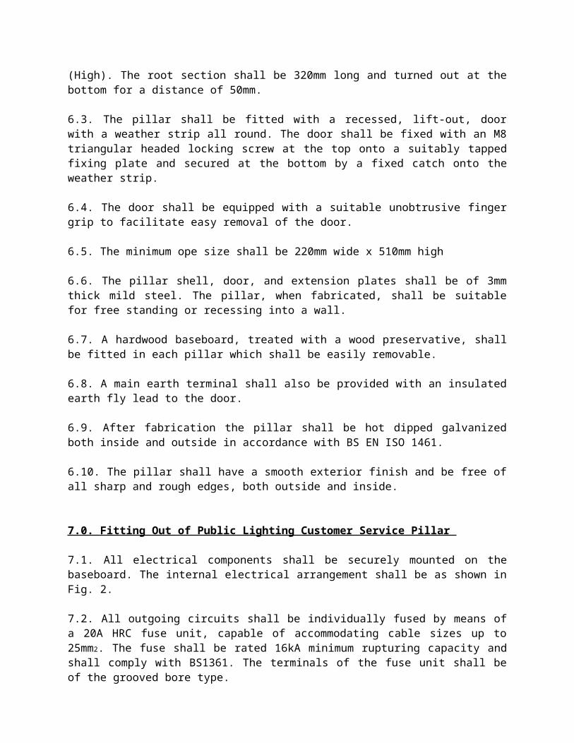
7.1. All electrical components shall be securely mounted on the baseboard. The internal electrical arrangement shall be as shown in Fig. 2.
7.2. All outgoing circuits shall be individually fused by means of a 20A HRC fuse unit, capable of accommodating cable sizes up to 25mm2. The fuse shall be rated 16kA minimum rupturing capacity and shall comply with BS1361. The terminals of the fuse unit shall be of the grooved bore type.
7.3. Where there is more than one outgoing circuit, a main fuse shall also be provided. The main fuse shall be rated 25A and shall otherwise be identical with individual circuit fuses.
7.4. The electrical contractor shall consult with the local ESB Networks office on ESB interface requirements at the Customer Service Pillar.

7.5. A bituminous protective coating shall be applied all around the extension plates and up to a level on the shell extending 100mm above the ground level marking.
7.6. The installed pillar shall be embedded in concrete, Class E, Clause 1502, Specification for Road-works, published by the Dept of the Environment.
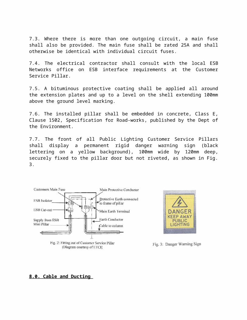
7.7. The front of all Public Lighting Customer Service Pillars shall display a permanent rigid danger warning sign (black lettering on a yellow background), 100mm wide by 120mm deep, securely fixed to the pillar door but not riveted, as shown in Fig. 3.
8.0. Cable and Ducting
8.1. All cabling shall be laid underground in 50mm PVC-U pipe coloured red of high density to IS 135 class B with a wall thickness in the range 2.3-2.8mm or other pipe coloured red having a high resistance to impact. The minimum standard acceptable is EN 50086-2-4 with a 750 Newton load rating for 5% deflection. A minimum cover of 600mm to the ducting shall be provided in grass margins and minimum cover of 750mm to the ducting shall be provided at road crossings. A spare duct shall be laid across all aprons.
8.2. Two core cable with a separate earth return path shall be used. Cables shall be either:
2 x 6mm2 NYCY type to VDE specification 0271/5or
3 x 6mm2 PVC/SWA/PVC type to BS 6346:1989, with colours brown, blue, and green-yellow.
8.3. Cable joints are not permitted. Cables shall be looped from column to column on each circuit. If faults develop on cables prior to commissioning, the section of cable involved shall be replaced.
8.4. A duct should be provided between the ESB section pillar and the Public Lighting Customer Service Pillar.
9.0. Earthing
9.1. All Customer Service Pillars shall be earthed, using an earth electrode and the supply neutralised. The electrode shall consist of a bare copper, or hot dipped galvanised steel rod/pipe of at least 16mm diameter, driven vertically into the soil for a length of at least 1,200mm. If difficulties arise in driving the vertical rod, due to underground services, a horizontal earth electrode may be installed as follows:
9.2. A straight length of at least 4.5m of either: 16mm diameter bare copper, 16mm diameter hot dipped galvanised steel rod, 25mm2 cross-section bare copper, 25mm2 cross-section hot dipped galvanised steel rod,
buried in the soil to a depth of at least 500mm. The earthing lead shall exit the pillar through the services cable entry opening.
9.3. The connection at the earth electrode shall be accessible for inspection and shall be protected against corrosion by a suitable waterproof tape. The connection shall be enclosed in a galvanised steel box, with an inspection cover. After inspection, the connection shall be buried underground.
9.4. A main earth terminal shall be mounted on the pillar baseboard, with the following connections: 10mm2 PVC cable from the earth terminal on the pillar, with a crimped lug connection to the
pillar, 10mm2 PVC cable from the earth electrode, 10mm2 PVC cable from the neutral link.
9.5. A main earth terminal shall be mounted on the baseboard in each lighting column, with the following connections:
6mm2 PVC cable from the earth terminal to the column, with a crimped lug connection to the column,
2.5mm2 PVC cable from the lantern earth terminal.
9.6. The outer sheath of the incoming and/or outgoing service cable shall be connected to the main earth terminal, in the case of both the lighting column and the public lighting customer service pillar.
9.7. If PVC/SWA/PVC cables are used, the outer sheath shall be terminated in an approved manner.
9.8. Earth continuity cables shall be coloured yellow/green, in accordance with ETCI wiring rules. In the case of NYCY cables, appropriate yellow/green sleeving shall be used.
10.0. Main Protective Conductor (“neutralising link”)
10.1. The main protective conductor connects the main earthing terminal to the ESB neutral in the Customer Service Pillar. This connection is made only by ESB where no isolator is fit-ted. In situations where the isolator is provided by the ESB, it is the responsibility of the con-tractor to connect the main protective conductor to the designated terminal on the isolator.
11.0. Supply Connections and Main Supply Point
11.1 The ESB Mini Pillar is the point of connection to the electricity Network. An under-ground cable connects this point to the ESB standard cut-out in the Customer Service Pillar. This in turn is connected to an isolator supplied and fitted by ESB Networks. The isolator is sealed in the off position. It is the responsibility of the contractor who constructed and tested the installation to connect the installation to the isolator and perform the post connection tests. 11.2. There shall be a separation of at least two metres between the ESB Mini-Pillar and the Customer Service Pillar. The purpose of this requirement is to avoid conflict between the ESB cable vaults and ducts, and the public lighting cables and ducts. Public lighting circuits shall not pass through the ESB Mini-Pillar vault. This distance may be reduced if segregation of ducting is ensured. In this situation the Mini-Pillar and the Customer Service Pillar must be cross bonded to one another with a 10mm2 copper conductor. This conductor shall be installed by the contractor, and it will be connected by ESB Networks at their Mini-Pillar.
12.0. Column Installation
12.1. Lighting column bases shall be treated internally and externally with a bituminous preservative to a height of 50mm above planting depth.
12.2. Where there is no grass verge, all columns shall be located to the back of the footway.
12.3. The excavation for lighting columns shall be a minimum of 500mm in diameter and 1.05 metres in depth.
12.4. Column erection shall be in three stages as follows:
Place 50mm of blinding concrete in the bottom of excavation. Concrete shall be Class E, Clause 1502, Specification for Road-works.
Erect column vertically and centrally on the blinding and surround the column with Grade 15.20 concrete, to a level 150mm below the cable entry slot. Concrete shall be class 30/20, Clause 1501, Specification for Roadwork’s.
The final one metre of incoming and outgoing supply cable, up to the cable entry slot, shall be protected by polyethylene piping, which shall extend 30mm into the column. The cable shall be kept level with the bottom of the entry slot, in order to avoid dam-age due to column settlement.
The column shall be positioned such that the base compartment faces away from the direction of on-coming traffic.
12.5. Alternatively, a column foundation may be supplied by the installation of a concrete or plastic sleeve. The sleeve type and installation information are shown in drawing PL/504/08 in section 16.4. 12.6. If any other services are exposed by the excavation, care shall be taken not to encase them in the concrete surround. If necessary, an approved separating barrier shall be used, in order to maintain service access.
12.7. Excavations shall be free of water when pouring the concrete surround. Columns shall be erected with the compartment door positioned on the side facing away from the direction of traffic
flow and shall be set back a minimum distance of one metre from the kerb edge. The installation shall be completed by properly backfilling the excavation to ground level.
13.0. Safety and Risk Assessment
13.1. Road-works: The installation of public lighting will require workers to carry out activities on or near public roads or footpaths. Many of these activities such as excavations, column installation, and work with electric cabling are high risk. In addition to the risks associated with the actual work activity, by being located on, or near to, public roads and footpaths, there are increased risks to both employees and public alike.
13.2. Traffic Management Safety: To ensure the safety of both employees and the public during the installation of public lighting the contractor will ensure that suitable and sufficient traffic management systems are planned and implemented. An important aspect of this safety process is the assessment of the risks to be faced and how traffic management systems will assist in controlling the risks.
13.3. Design brief and risk assessment: There are specific obligations on designers. The design of the installation shall include a risk assessment and shall include specific information that will have an impact on the final traffic/pedestrian management system chosen. This shall include the following:
Location of the works (nearness to specific risks such as schools, hospitals, etc).
Time that work shall take place (peak hours, off-peak hours, during the day, at night).
Type and volume of traffic to be expected.
Type of road (motorway, national rd, regional rd, local rd, etc).
Speed limit and road characteristics
Type of pedestrian traffic to be encountered (local activities will be a reference).
Work to take place and duration.
Equipment and materials to be used and stored on site
Weather conditions and local environment conditions
Location of services beneath the road.
14.0. Legislative requirements:
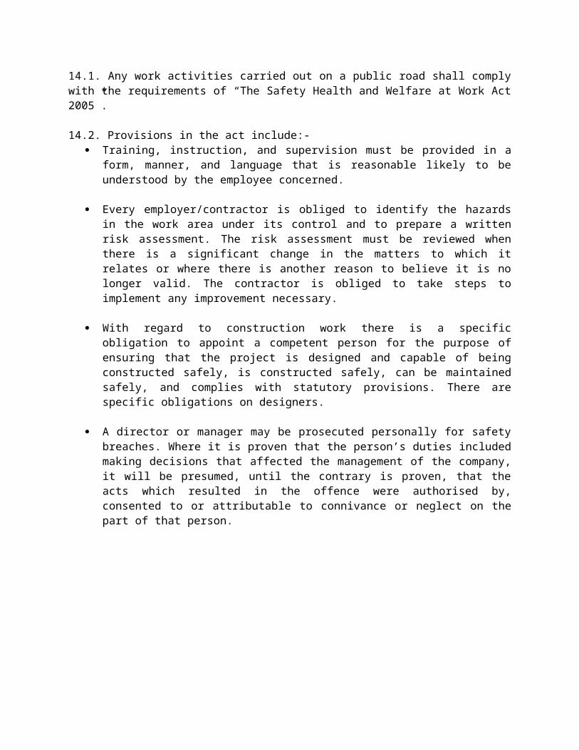
14.1. Any work activities carried out on a public road shall comply with the requirements of “The Safety Health and Welfare at Work Act 2005”.
14.2. Provisions in the act include:- Training, instruction, and supervision must be provided in a form, manner, and language that
is reasonable likely to be understood by the employee concerned.
Every employer/contractor is obliged to identify the hazards in the work area under its control and to prepare a written risk assessment. The risk assessment must be reviewed when there is a significant change in the matters to which it relates or where there is another reason to believe it is no longer valid. The contractor is obliged to take steps to implement any improvement necessary.
With regard to construction work there is a specific obligation to appoint a competent person for the purpose of ensuring that the project is designed and capable of being constructed safely, is constructed safely, can be maintained safely, and complies with statutory provisions. There are specific obligations on designers.
A director or manager may be prosecuted personally for safety breaches. Where it is proven that the person’s duties included making decisions that affected the management of the company, it will be presumed, until the contrary is proven, that the acts which resulted in the offence were authorised by, consented to or attributable to connivance or neglect on the part of that person.
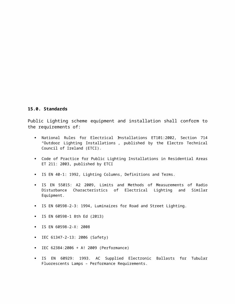
15.0. Standards
Public Lighting scheme equipment and installation shall conform to the requirements of:
National Rules for Electrical Installations ET101:2002, Section 714 “Outdoor Lighting Installations”, published by the Electro Technical Council of Ireland (ETCI).
Code of Practice for Public Lighting Installations in Residential Areas ET 211: 2003, published by ETCI
IS EN 40-1: 1992, Lighting Columns, Definitions and Terms.
IS EN 55015: A2 2009, Limits and Methods of Measurements of Radio Disturbance Characteristics of Electrical Lighting and Similar Equipment.
IS EN 60598-2-3: 1994, Luminaires for Road and Street Lighting.
IS EN 60598-1 8th Ed (2013)
IS EN 60598-2-X: 2008
IEC 61347-2-13: 2006 (Safety)
IEC 62384:2006 + A! 2009 (Performance)
IS EN 60929: 1993. AC Supplied Electronic Ballasts for Tubular Fluorescents Lamps – Performance Requirements.
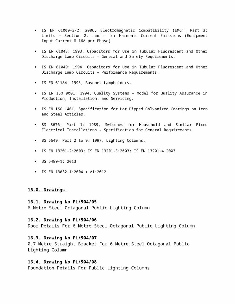
IS EN 61000-3-2: 2006, Electromagnetic Compatibility (EMC). Part 3: Limits – Section 2: limits for Harmonic Current Emissions (Equipment Input Current 16A per Phase)
IS EN 61048: 1993, Capacitors for Use in Tubular Fluorescent and Other Discharge Lamp Circuits – General and Safety Requirements.
IS EN 61049: 1994, Capacitors for Use in Tubular Fluorescent and Other Discharge Lamp Circuits – Performance Requirements.
IS EN 61184: 1995, Bayonet Lampholders.
IS EN ISO 9001: 1994, Quality Systems – Model for Quality Assurance in Production, Installation, and Servicing.
IS EN ISO 1461, Specification for Hot Dipped Galvanized Coatings on Iron and Steel Articles.
BS 3676: Part 1: 1989, Switches for Household and Similar Fixed Electrical Installations – Specification for General Requirements.
BS 5649: Part 2 to 9: 1997, Lighting Columns.
IS EN 13201-2:2003; IS EN 13201-3:2003; IS EN 13201-4:2003
BS 5489-1: 2013
IS EN 13032-1:2004 + A1:2012
16.0. Drawings
16.1. Drawing No PL/504/05
6 Metre Steel Octagonal Public Lighting Column
16.2. Drawing No PL/504/06 Door Details For 6 Metre Steel Octagonal Public Lighting Column
16.3. Drawing No PL/504/07 0.7 Metre Straight Bracket For 6 Metre Steel Octagonal Public Lighting Column
16.4. Drawing No PL/504/08 Foundation Details For Public Lighting Columns
16.1. PL/504/05
16.2. PL/504/06
16.3. PL/504/07
16.4. PL/504/08
17.0. Sample List Of Approved Suppliers
Philips WRTL Lighting Thorn Lighting Siteco Urbis Schreder D W Windsor Holophane
Note: Consideration will be given to other suppliers subject to the lanterns offered complying with the requirements herein.