Embed Size (px)
Citation preview
QUESTION BANK 2016
Power Electronics Page 1
Prepared by:M.sreenivasulu reddy
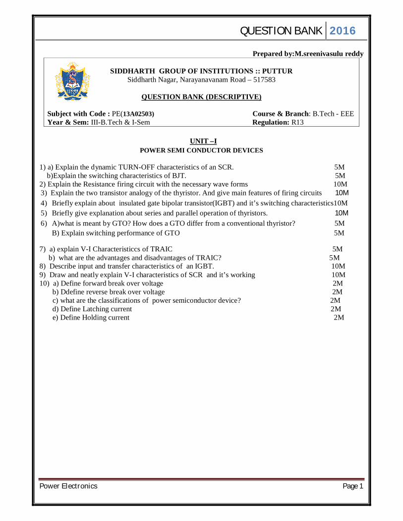
SIDDHARTH GROUP OF INSTITUTIONS :: PUTTUR Siddharth Nagar, Narayanavanam Road – 517583
QUESTION BANK (DESCRIPTIVE)
Subject with Code : PE(13A02503) Course & Branch: B.Tech - EEE Year & Sem: III-B.Tech & I-Sem Regulation: R13
UNIT –I
POWER SEMI CONDUCTOR DEVICES
1) a) Explain the dynamic TURN-OFF characteristics of an SCR. 5M b)Explain the switching characteristics of BJT. 5M 2) Explain the Resistance firing circuit with the necessary wave forms 10M 3) Explain the two transistor analogy of the thyristor. And give main features of firing circuits 10M 4) Briefly explain about insulated gate bipolar transistor(IGBT) and it’s switching characteristics10M 5) Briefly give explanation about series and parallel operation of thyristors. 10M 6) A)what is meant by GTO? How does a GTO differ from a conventional thyristor? 5M
B) Explain switching performance of GTO 5M
7) a) explain V-I Characteristiccs of TRAIC 5M b) what are the advantages and disadvantages of TRAIC? 5M 8) Describe input and transfer characteristics of an IGBT. 10M 9) Draw and neatly explain V-I characteristics of SCR and it’s working 10M 10) a) Define forward break over voltage 2M b) Ddefine reverse break over voltage 2M c) what are the classifications of power semiconductor device? 2M d) Define Latching current 2M e) Define Holding current 2M

QUESTION BANK 2016
Power Electronics Page 2
UNIT –II PHASE CONTROLLED CONVERTERS
1) Explain the operation of single phase semi converter with RLE load by using freewheeling diode with necessary output wave forms. 10M 2)Explain the operation of single phase half controlled bridge converter with RL-Load at α=60 with necessary wave forms. Also derive the output voltage , output current and RMS output voltages. 10M 3.) Explain the operation of single phase full wave midpoint converter for RL load at a α =60deg with necessary output wave waveforms. Also derive the output voltage, output current & Rms voltage equations. 10M 4) What is a freewheeling diode? Draw the circuit diagram of an SCR full wave rectifier with RL load For with and with out freewheeling diode and explain the operation with necessary output waveforms 10M 5)a) Give the difference between midpoint and bridge type converters 5M b) Give the difference between discontinuous mode and continuous mode of operation 5M 6) a)what are the difference between half controlled and fully controlled bridge rectifier? 5M b) What are the effects of source inductance in controlled rectifier? 5M 7) Explain the operation of three phase half controlled rectifier with different loads. 10M 8) Explain the operation of 3 phase fully controlled rectifier with resistive laod and also derive the average and RMS load voltage 10M 9) A single phase half wave converter is operated from a 120v,60Hz supply. 10M If the load is resistive of value 10 ohms and delay angle is alpha is 60. Determine i) the efficiency ii)formfactor iii)ripple factor iv) Transformer utilization factor v)peak inverse voltage of thyristor . 10) a) what is meant my phase controlled rectifier? 2M b) what is meant by uncontrolled rectifier? 2M c) what is meant by half controlled rectifier 2M d) what is meant by full converter? 2M e) mention some application of controlled rectifier? 2M
QUESTION BANK 2016
Power Electronics Page 3
UNIT-III CHOPPERS 1.(a) Explain about the jones chopper with circuit diagram and wave forms? 5M (b) Explain about the AC chopper with circuit diagram and wave forms? 5M 2.a) Describe the the principle of dc chopper operation. 5M b) Derive an expression for it’s average dc output voltage 5M 3.explain the step-up chopper operation with help of neat diagram? 10M 4.with the help of basic power circuit diagram explain the working of a current commutated chopper. also , Draw the associated wave forms. 10M 5.Derive the expression for output voltage of step up chopper with neat diagrams 10M 6.a)what are the advantages of current commutated chopper? 5M b)Discuss the main classification of dc to dc converters 5M 7.a)what are the advantages and disadvantages of load commutated chopper? 5M b)what is meant my dc chopper explain with neat circuit diagram 5M 8.Describe the principle of dc chopper operation. derive an expression for its average dc output voltage 10M 9.what is a dc chopper? describe various types of chopper configurations with appropriate diagram wherever necessary 10M 10.a)what are the advantages of dc chopper 2M b)what are the applications of dc chopper 2M c)what is meant by duty cycle 2M d)what is meant by step-down chopper 2M e)what is meant by step-up chopper 2M
QUESTION BANK 2016
Power Electronics Page 4
UNIT- IV INVERTERS
1.a) explain the operation of parallel inverter 5M b)Explain the operation of series inverter 5M 2. Explain the operation of single phase half bridge voltage source inverter 10M 3.Draw and explain the simple SCR series inverter circuit. Draw and discuss the important waveforms. State the limitations of this series inverter. 10M 4.Explain the operation of single phase full bridge voltage source inverter and the help of voltage and current waveforms? 10M 5. a) what are the advantages of PWM ? 5M b)List various PWM techniques 5M 6.Describe different types of pulse width modulation techniques (PWM) inverter 10M 7.Explain different methods of harmonic reduction in inverters 10M 8.Explain the operation of Basic Parallel Capacitor Inverter Bridge Inverter 10M 9. Explain about Voltage Control Techniques for Inverters 10M 10.a)what are the applications of inverters? 2M b)what is meant by VSI 2M c)what are the different methods for forced commutation employed in inverter circuits? 2M d)what is meant by PWM control? 2M e)what is meant by series inverter? 2M

QUESTION BANK 2016
Power Electronics Page 5
UNIT- V AC VOLTAGE CONTROLLERS & CYCLO CONVERTERS
1. Explain about the 1 – Ø AC voltage controller with R & RL loads with circuit diagram and wave forms? 10M 2. Briefly explain the operation of TRIAC in different modes 10M 3.a)what is meant by ac voltage controllers and what are the different types? 5M b)list the applications of ac voltage controller. 5M 4.Explain the principle of operation of single phase to single phase mid point cycloconverter 10M 5.Explain the basic principle of operation of step up cyclonverter. 10M 6.Describe the principle of working of single phase to single phase cycloconverter For both continuous and discontinuous conduction for a bridge type cycloconverter . 10M 7.what is meant by by load commutated cycloconverter ? how does it differ from force commutated and line commutated cycloconverter? 10M 8.Explain the operation of single phase ac voltage controller with resistive load 10M 9. Explain the operation of Triac with R And RL Loads 10M 10.a)what is meant by acd voltage controller? 2M b)what are the applications of ac voltage controller? 2M c)what are the advantages and disadvantages of ac voltage controller? 2M d)what is meant by cycloconverter? 2M e)what are the applications of cycloconverter? 2M
QUESTION BANK 2016
Power Electronics Page 6
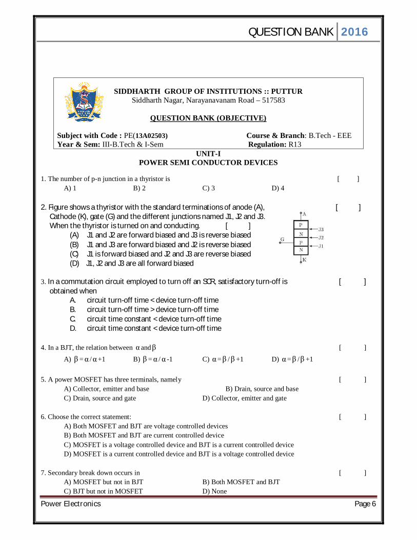
SIDDHARTH GROUP OF INSTITUTIONS :: PUTTUR
Siddharth Nagar, Narayanavanam Road – 517583
QUESTION BANK (OBJECTIVE)
Subject with Code : PE(13A02503) Course & Branch: B.Tech - EEE Year & Sem: III-B.Tech & I-Sem Regulation: R13
UNIT-I POWER SEMI CONDUCTOR DEVICES
1. The number of p-n junction in a thyristor is [ ] A) 1 B) 2 C) 3 D) 4 2. Figure shows a thyristor with the standard terminations of anode (A), [ ] Cathode (K), gate (G) and the different junctions named J1, J2 and J3. When the thyristor is turned on and conducting. [ ]
(A) J1 and J2 are forward biased and J3 is reverse biased (B) J1 and J3 are forward biased and J2 is reverse biased (C) J1 is forward biased and J2 and J3 are reverse biased (D) J1, J2 and J3 are all forward biased
3. In a commutation circuit employed to turn off an SCR, satisfactory turn-off is [ ] obtained when
A. circuit turn-off time < device turn-off time B. circuit turn-off time > device turn-off time C. circuit time constant < device turn-off time D. circuit time constant < device turn-off time
4. In a BJT, the relation between α andβ [ ]
A) β = α / α +1 B) β = α / α -1 C) α =β / β +1 D) α =β /β +1
5. A power MOSFET has three terminals, namely [ ] A) Collector, emitter and base B) Drain, source and base C) Drain, source and gate D) Collector, emitter and gate
6. Choose the correct statement: [ ] A) Both MOSFET and BJT are voltage controlled devices
B) Both MOSFET and BJT are current controlled device C) MOSFET is a voltage controlled device and BJT is a current controlled device D) MOSFET is a current controlled device and BJT is a voltage controlled device
7. Secondary break down occurs in [ ] A) MOSFET but not in BJT B) Both MOSFET and BJT
C) BJT but not in MOSFET D) None

QUESTION BANK 2016
Power Electronics Page 7
8. The conduction loss versus device current characteristic of a power MOSFET is best approximated by [ ]
A) a parabola B) a straight line B) a rectangular hyperbola D)an exponentially decaying function
9. Match list-I(devices ) with list-II(switching time) and select correct answer using code given below the lists: [ ]
List-I list-II A. TRIAC 1. 5-10µs B. SCR 2. 100-400 µs C. MOSFET 3. 50-100 µs D. IGBT 4.200-400 µs
Codes: A B C D (a) 4 3 2 1 (b) 1 2 3 4 (c) 4 2 3 1 (d) 1 3 2 4
10. A thyristor has a PIV of 650 V. The voltage safety factor is 2. Then the voltage up to which the device can be operated is given by [ ]
A) 1300V B) 650V C) 325V D) 230V 11. An SCR triggered by a current pulse applied to the gate cathode can be turned off [ ]
A) By applying a pulse to the cathode B) By applying a pulse to the anode C) By applying another pulse of opposite polarity to the gate cathode D) By reversing the polarity of the anode and cathode voltage
12. A dc source of 100 v supplies a purely inductive load of 0.1 H. The controller is an SCR in series with source and load. If the specified latching current is 100ma then the minimum width of the gating pulse to ensure turn on of SCR would be [ ] A) 10µs B) 50 µs C) 100 µs D) 1 µs 13. The most suitable device for high frequency inversion in SMPS is [ ]
(a) BJT (b) IGBT (c) MOSFET (d) GTO 14. A modern power semiconductor device that combines the characteristics of BJT & MOSFET is [ ] A) GTO B)FCT C)IGBT D)MCT 15. Consider the following statements [ ]
1) A thyristor requires turn off circuit while transistor does not 2) The voltage drop of a thyristor is less than that of a transistor 3) A thyristor require a continuous gate current
QUESTION BANK 2016
Power Electronics Page 8
4) A transistor draws continuous base current Which of these statements are correct? A) 1, 2, 3 & 4 B) 1 & 2 C) 2 & 4 D) 1 & 4 16. di/dt protection for an SCR is achieved by [ ] A) R in series with SCR B) L in series with SCR C) R across SCR D) L across SCR 17. R-C snubber is used in parallel with the thyristor [ ]
A) Reduce dv /dt across it B) reduce di/dt through it C) limit current through it D) ensure its conduction after gate signal is removed
18. Sharing of voltage between thyristors operating in series is influenced by the [ ]
A) Di/dt capabilities B) dv/dt capabilities C) Junction temperature D) static V-I characteristics and leakage current
19. Turn on and Turn off time of transistor depends on [ ]
A) static characteristics B) junction capacitance C) current gain D) none of the above
20. Which of the following are UJT Parameters and Ratings? [ ]
A) Maximum reverses emitter voltage B) Maximum interbase voltage C) Maximum peak emitter current D) All the above
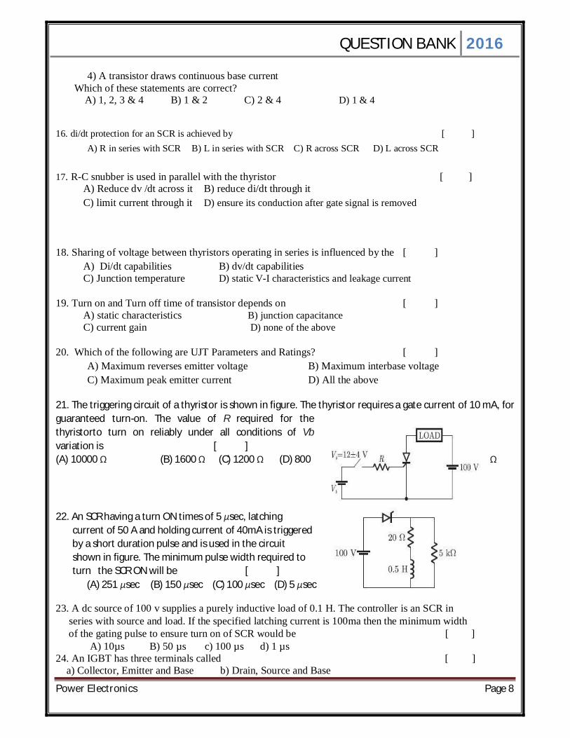
21. The triggering circuit of a thyristor is shown in figure. The thyristor requires a gate current of 10 mA, for guaranteed turn-on. The value of R required for the thyristorto turn on reliably under all conditions of Vb variation is [ ] (A) 10000 Ω (B) 1600 Ω (C) 1200 Ω (D) 800 Ω 22. An SCR having a turn ON times of 5 μsec, latching current of 50 A and holding current of 40mA is triggered by a short duration pulse and is used in the circuit shown in figure. The minimum pulse width required to turn the SCR ON will be [ ] (A) 251 μsec (B) 150 μsec (C) 100 μsec (D) 5 μsec 23. A dc source of 100 v supplies a purely inductive load of 0.1 H. The controller is an SCR in series with source and load. If the specified latching current is 100ma then the minimum width of the gating pulse to ensure turn on of SCR would be [ ] A) 10µs B) 50 µs c) 100 µs d) 1 µs 24. An IGBT has three terminals called [ ] a) Collector, Emitter and Base b) Drain, Source and Base
QUESTION BANK 2016
Power Electronics Page 9
c) Drain, Source and Gate d) Collector, Emitter and Gate 25. The function of snubber circuit connected across the SCR is to [ ] a) Suppress dv/dt b) Increase dv/dt c) Decrease dv/dt d) Decrease di/dt [ ] 26. An UJT exhibits negative resistance region: a) Before the break point b) Between peak and valley point c) After the valley point d) Both (a) and (c) 27. For dynamic equalizing circuit used for series connected SCRs, the choice of C is based on: [ ] a) Reverse recovery characteristics b) Turn-on characteristics c) Turn-off characteristics d) Rise time characteristics 28. The frequency of the ripple in the output voltage of 3-phase semiconductor depends on: [ ] a) Firing angle and load resistance b) Firing angle and load inductance c) The load circuit parameters d) Firing angle and the supply frequency 29. Practical way of obtaining static voltage equalization in series connected SCRs is by the use of: [ ] a) One resistor across the string b) Resistors of different values across each SCR c) Resistors of the same value across each SCR d) One resistor in series with each SCR 30. A resistor connected across the gate and cathode of an SCR in a circuit increases its [ ] a) dv/dt rating b) Holding current c) Noise Immunity d) Turn-off time 31. A Triac has three terminals viz ……………… [ ] a)Drain, source, gate b)Two main terminal and a gate terminal c)Cathode, anode, gate d)None of the above 32. A triac is equivalent to two SCRs ………….. [ ] a)In parallel b)In series c)In inverse-parallel d)None of the above 33. A triac is a …………. Switch [ ] a) Bidirectional b)Unidirectional c)Mechanical d)None of the above 34. The V-I characteristics for a triac in the first and third quadrants are essentially identical to those of ………………. in its first quadrant [ ] a)Transistor b)SCR c)UJT d)none of the above 35. A triac can pass a portion of …………… half-cycle through the load [ ] a)Only positive b)Only negative c)Both positive and negative d)None of the above 36. A diac has ………….. terminals [ ]

QUESTION BANK 2016
Power Electronics Page 10
a)Two b)Three c)Four d)None of the above 37. A triac has …………….. semiconductor layers [ ] a)Two b)Three c)Four d)Five 38. A diac has …………… pn junctions [ ] a)Four b)Two c)Three d)None of the above 39. The device that does not have the gate terminal is ………………. [ ] a)Triac b)FET c)SCR d)Diac 40. A diac has ……………… semiconductor layers [ ] a)Three b)Two c)Four d)None of the above
QUESTION BANK 2016
Power Electronics Page 11
UNIT-II PHASE CONTROLLED CONVERTERS
1. A single phase half wave circuit is one which produces number of pulses of load current during one cycle of source voltage. [ ] A) 2 B) 3 C) 6 D) 1 2. In a single phase semi converter with resistive load and for a firing angle of α, each SCR and freewheeling diode conducts respectively for [ ] A)α,00 B)Π -α, α C) Π + α, α D) - α, 00 3. In a single phase semi converter if output voltage has peak and average value of 325V and 133V respectively, then the firing angle is__________ [ ] A) 400 B) 1400 C) 73.400 D) 800 4. Freewheeling diode is also know as [ ]
A) commutating diode B) fly wheel diode C) by pass diode D) all the above
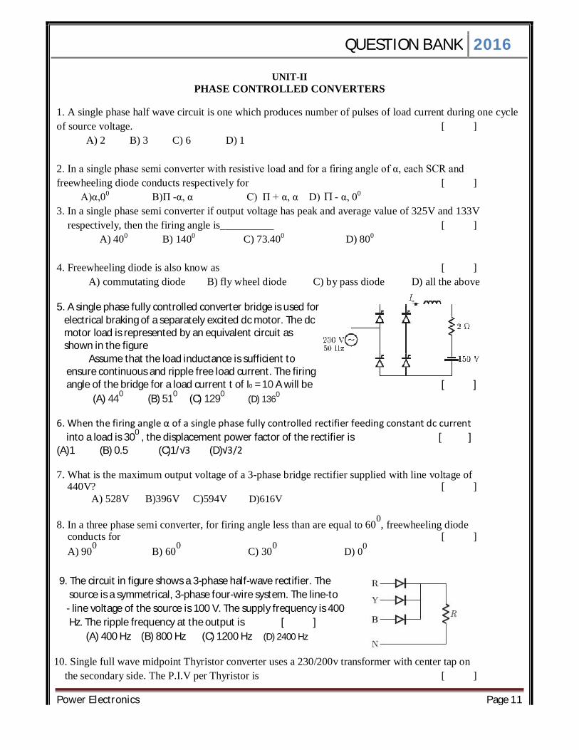
5. A single phase fully controlled converter bridge is used for electrical braking of a separately excited dc motor. The dc motor load is represented by an equivalent circuit as shown in the figure
Assume that the load inductance is sufficient to ensure continuous and ripple free load current. The firing angle of the bridge for a load current t of I0 = 10 A will be [ ]
(A) 440 (B) 510 (C) 1290 (D) 1360 6. When the firing angle α of a single phase fully controlled rectifier feeding constant dc current into a load is 300 , the displacement power factor of the rectifier is [ ] (A)1 (B) 0.5 (C)1/√3 (D)√3/2 7. What is the maximum output voltage of a 3-phase bridge rectifier supplied with line voltage of 440V? [ ]
A) 528V B)396V C)594V D)616V
8. In a three phase semi converter, for firing angle less than are equal to 600, freewheeling diode conducts for [ ] A) 900 B) 600 C) 300 D) 00
9. The circuit in figure shows a 3-phase half-wave rectifier. The source is a symmetrical, 3-phase four-wire system. The line-to - line voltage of the source is 100 V. The supply frequency is 400 Hz. The ripple frequency at the output is [ ] (A) 400 Hz (B) 800 Hz (C) 1200 Hz (D) 2400 Hz
10. Single full wave midpoint Thyristor converter uses a 230/200v transformer with center tap on the secondary side. The P.I.V per Thyristor is [ ]

QUESTION BANK 2016
Power Electronics Page 12
(A) 400 (B) 1400 (C) 500 (D) 1300 11. Each thyristor of a 3 half-wave controlled rectifier conducts for [ ]
A) 600 B) 1200 C) 1800 D) 900 12. A converter which can operate in both 3 pulse and 6 pulse modes is a [ ] A) 1- full converter B) 3 half wave converter C) 3 semi converter D) 3 full converter 13. The effect of source inductance on the performance of single-phase and three phase full converters is to [ ]
A) Reduce the ripples in the load current B) Make discontinuous current as continuous C) Reduce the output voltage D) Increase the load voltage
14. A three phase fully controlled bridge converter is feeding a load drawing a constant and ripple free load current of 10 A at a firing angle of 300. The approximate Total harmonic Distortion (%THD) and the rms value of fundamental component of input current will respectively be [ ]
(A) 31% and 6.8 A (B) 31% and 7.8A
(C) 66% and 6.8 A (D) 66% and 7.8 A
15. In circulating – current type of dual converter, the nature of voltage across reactor is [ ] A) alternating B) pulsating C) direct D) Triangular 16. In a 3 full converter, the six SCRs are fired at an interval of [ ] A) 300 B) 900 C) 1200 D) 600 17. A single-phase fully controlled thyristor bridge ac-dc converter is operating at a firing angle of 250and an overlap angle of 10c with constant dc output current of 20 A. The fundamental power factor (displacement factor) at input ac mains is [ ] (A) 0.78 (B) 0.827 (C) 0.866 (D) 0.9 18. A six pulse thyristor rectifier bridge is connected to a balanced 50 Hz three phase ac source. Assuming that the dc output current of the rectifier is constant, the lowest frequency harmonic component in the ac source line current is [ ] (A) 100 Hz (B) 150 Hz (C) 250 Hz (D) 300 Hz 19. For a single phase ac to dc controlled rectifier to operate in regenerative mode, which of the following conditions should be satisfied? [ ]
A) Half controlled bridge, α<90 deg , source of emf in load B) Half controlled bridge, α>90 deg , source of emf in load C) Full controlled bridge, α>90 deg , source of emf in load D) Full controlled bridge, α<90 deg , source of emf in load
20. The relation between firing angles of anti parallel converters of dual converter in circulating current mode of operation is [ ] (A) Π = α1 + α2 (B) Π - α1 = α2 (C) α1 + α2 = 1800 (D) all 21. For full-wave rectified sine wave, rms value is [ ]

QUESTION BANK 2016
Power Electronics Page 13
(a) 0.707 im (b) 0.6036 im (c)0.5 im (d) 0.318 im .
22. For full-wave rectified sine wave, mean value is [ ]
(a) 0.70 im (b) 0.636 im
(c) 0.5 im (d) 0.318 lm.
23.For full-wave rectified sine wave, form factor is [ ]
(a) 1.5 (b) 1.41
(c) 1.28 (d) 1.11.
24.The ripple factor of a full-wave rectifier circuit compared to that of a half wave rectifier circuit without filter is [ ]
(a) half of that for a half 'wave rectifier (b) less than half that for a half-wave rectifier circuit
(c) equal to that of a half wave rectifier. (d) none of the above.
25. A thyristor equivalent of a thyratron tube is a [ ]
(a) Silicon controlled rectifier (SCR) (b)Triac
(c) Diac (d) None of the above.
26. For single phase supply frequency of 50 Hz, ripple frequency in full
wave rectifier is [ ]
(a) 25 (b) 50
(c)100 (d) 200.
27. A rectifier is a [ ]
(a) Bilateral device (b) Linear device
(c) Non-linear device (d) Passive device.
28. In the process of diode based rectification, the alternating input

QUESTION BANK 2016
Power Electronics Page 14
voltage is converted into [ ] (a) an uncontrolled alternating output voltage (b) an uncontrolled direct output voltage (c) a controlled alternating output voltage (d) a controlled direct output voltage
29. Explanation: Rectification is AC to DC. In DIODE biased rectification,
control is not possible.In a half-wave rectifier, the........ [ ] a) current & voltage both are bi-directional b) current & voltage both are uni-directional c) current is always uni-directional but the voltage can be bi-directional or uni-directional d) current can be bi-directional or uni-directional but the voltage is always uni-directional
30. For a certain diode based rectifier, the output voltage (average value) is given by the equation 1/2π [ ∫Vm sin ωt d(ωt) ] Where the integral runs from 0 to π The rectifier configuration must be that of a [ ] a) single phase full wave with R load b) single phase full wave with RL load c) single phase half wave with R load d) single phase half wave with RL load
31. For a single phase half wave rectifier, with R load, the diode is reversed biased from ωt = [ ] a) 0 to π, 2π to 2π/3 b) π to 2π, 2π/3 to 3π c) π to 2π, 2π to 2π/3 d) 0 to π, π to 2π
32. In a 1-Phase HW diode rectifier with R load, the average value of load current is given by
Take Input (Vs) = Vm sinωt [ ] a) Vm/R b) Vm/2R c) Vm/πR d) Zero
33. A 3phase half controlled bridge converter consists of [ ] a) 3 diodes and 6 thyristors b) 3 diodes and 3 thyristors c) 3 diodes and 5 thyristors d) none 34. The pulse number of a 3phase fully controlled bridge converter is [ ] a) six b)nine c)twelve d) three 35. Due to source inductance which is reduced [ ] a) average current b) average dc voltage c) average power d)none 36.In3-ⱷ full wave rectifier duration of pulse and thyristor conduction period are [ ] a)600,1200 b) 600,600 c)1200 , 600 d) 1200 , 1200 37. A converter which can operate both in 3 pulse & 6 pulse modes is a …….. [ ] a)Single phase full converter b) 3 phase half wave converter c) 3 phase semi converter d) 3 phase full converter 38.A three phase semi converter can work as…………. [ ] a)Converter for α=00 to 1800 b)Converter for α=00 to 900
c)Inverter for α=900 to 1800 d)Inverter for α=00 to 900
39.In a 3-phase full converter, the output voltage during overlap is equal to [ ]

QUESTION BANK 2016
Power Electronics Page 15
a)Zero b)Source voltage c)Source voltage minus the inductance drop d)average value of the conducting-phase voltages 40.A single phase diode bridge rectifier supplies a highly inductive load. The load current can be assumed to be ripple free. The ac supply side current waveform will be [ ] a) sinusoidal b)constant dc c)square d)triangle
QUESTION BANK 2016
Power Electronics Page 16
UNIT-III
CHOPPERS
1. In a dc choppers, if T is the chopping period then output voltage can be controlled by varying. (a) T, Ton constant (b) Ton, T constant [ ] (c) T, Toff constant (d) All
2. A step-up chopper has VS as the source voltage and as duly cycle. The Output voltage for this chopper is given by [ ]
(a) VS (1+) (b) VS/ (1- ) (c) VS (1- ) (d) VS/ (1+) 3. The conjugation of step-up chopper is used in _____ [ ] (a) dynamic braking (b) regeneration braking (c) plugging (d) all 4. Which chopper is the example for class –D commutation? [ ] (a) Step-up chopper (b) Oscillation chopper (c) morgans chopper (d) jones chopper 5. A chopper has VS as the source voltage , R as the load resistance and the duty cycle For this chopper, rms value of o/p voltage is [ ] (a) VS (b) VS (c) VS / (d) 1 VS 6. Chopper can be used as [ ] (a) Pulse – width modulation only (b) Frequency modulation only (c) Amplitude modulation only (d) Both pwm and Fm 7. In d.c. chopper, the wave forms for input and output voltages are respectively [ ] (a) discontinuous, continuous (b) both continuous (c) both discontinuous (d) continuous, discontinuous 8. In d.c. choppers if Ton is the on period and f is the chopping frequency, then output [ ] voltage is given by
(a) f
TV onS
(b)
onS T
fV (c) onS Tf
V.
(d) onS TfV ..
9. In time ratio control (TRC) the controlled output is obtained by varying [ ]
(a) T
Ton (b) onTT (c)
fT
(d) Tf
10. For type – A chopper, VS is the source voltage; R is the load resistance and is the duty cycle. The average output voltage and current for this chopper are respectively. [ ]
(a)
RV
V SS , (b)
RVV S
S
1,1
(c) R
VV SS
, (d) R
VV SS
1,
1
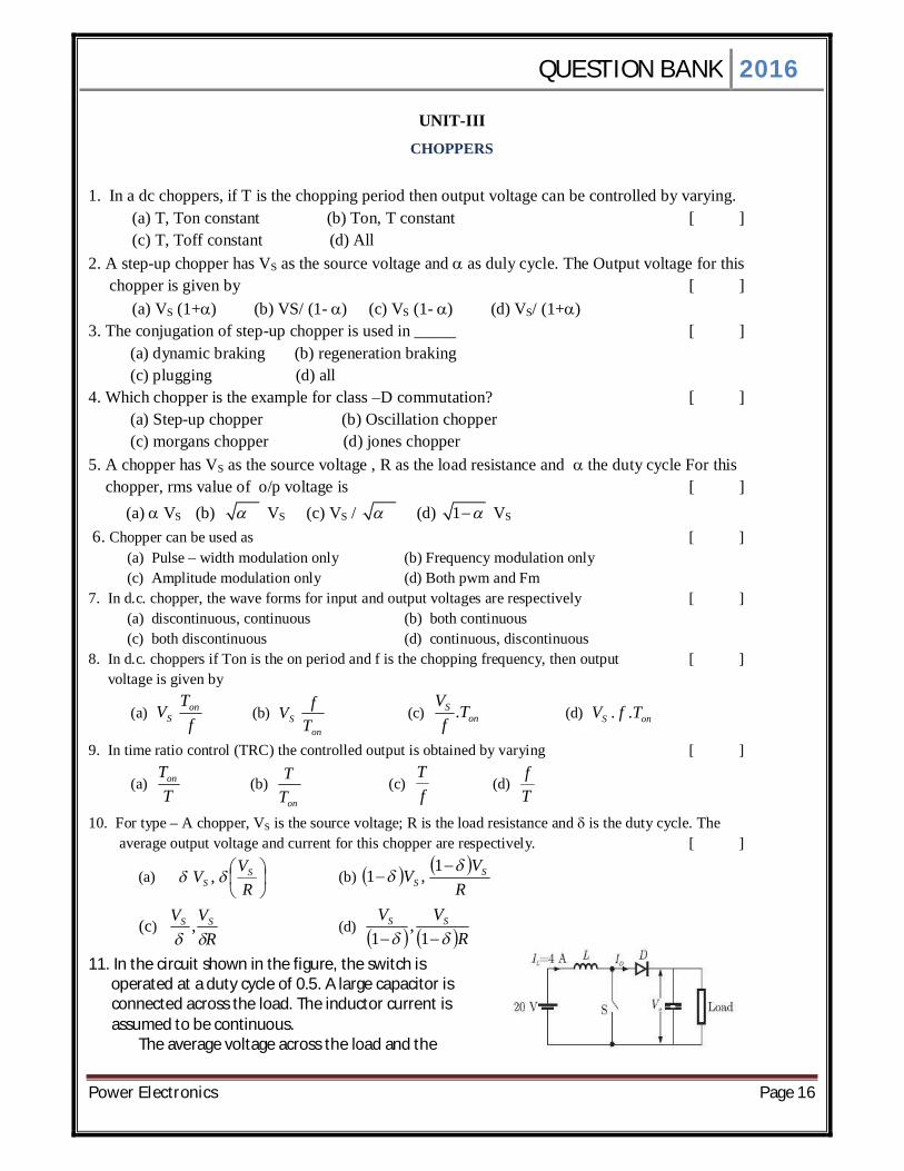
11. In the circuit shown in the figure, the switch is operated at a duty cycle of 0.5. A large capacitor is connected across the load. The inductor current is assumed to be continuous.
The average voltage across the load and the
QUESTION BANK 2016
Power Electronics Page 17
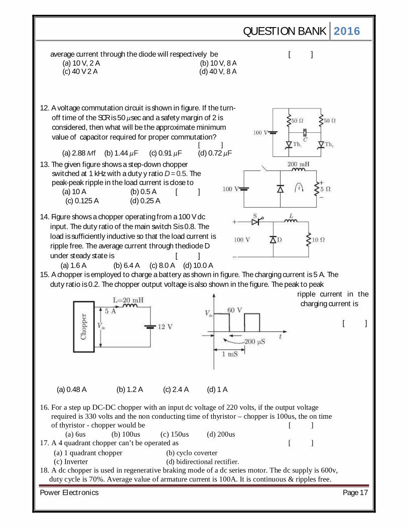
average current through the diode will respectively be [ ] (a) 10 V, 2 A (b) 10 V, 8 A (c) 40 V 2 A (d) 40 V, 8 A
12. A voltage commutation circuit is shown in figure. If the turn- off time of the SCR is 50 μsec and a safety margin of 2 is considered, then what will be the approximate minimum value of capacitor required for proper commutation? [ ] (a) 2.88 Μf (b) 1.44 μF (c) 0.91 μF (d) 0.72 μF 13. The given figure shows a step-down chopper switched at 1 kHz with a duty y ratio D = 0.5. The peak-peak ripple in the load current is close to (a) 10 A (b) 0.5 A [ ]
(c) 0.125 A (d) 0.25 A
14. Figure shows a chopper operating from a 100 V dc input. The duty ratio of the main switch S is 0.8. The load is sufficiently inductive so that the load current is ripple free. The average current through thediode D under steady state is [ ] (a) 1.6 A (b) 6.4 A (c) 8.0 A (d) 10.0 A 15. A chopper is employed to charge a battery as shown in figure. The charging current is 5 A. The duty ratio is 0.2. The chopper output voltage is also shown in the figure. The peak to peak ripple current in the
charging current is
[ ] (a) 0.48 A (b) 1.2 A (c) 2.4 A (d) 1 A 16. For a step up DC-DC chopper with an input dc voltage of 220 volts, if the output voltage required is 330 volts and the non conducting time of thyristor – chopper is 100us, the on time of thyristor - chopper would be [ ]
(a) 6us (b) 100us (c) 150us (d) 200us 17. A 4 quadrant chopper can’t be operated as [ ]
(a) 1 quadrant chopper (b) cyclo coverter (c) Inverter (d) bidirectional rectifier.
18. A dc chopper is used in regenerative braking mode of a dc series motor. The dc supply is 600v, duty cycle is 70%. Average value of armature current is 100A. It is continuous & ripples free.

QUESTION BANK 2016
Power Electronics Page 18
What is the value of power feedback to the supply? [ ] (a) 3 KW (b) 9KW (c)18KW (d)35KW 19. In a type-A chopper, source voltage is 100 V, d.c. on-period = 100 ms, off-period = 150 ms and load RLE consists of R = 2Ω, L = 5 mH, E = 10 V. For continuous conduction average output voltage and average output current for this chopper
are respectively: [ ]
(a) 40 V, 15 A (b) 66.66 V, 28.33 A (c) 60 V, 25 A (d) 40 V, 20 A
20. A dc to dc transistor chopper supplied from a fixed voltage dc source feeds a fixed-resistive- inductive load and a free-wheeling diode. The chopper operates at 1 kHz and 50% duty cycle. Without changing the value of the average dc current through the load, if it is desired to reduce the ripple content of load current, the control action needed will [ ]
(a) increase the chopper frequency keeping the duty cycle constant (b) increase the chopper frequency and duty cycle in equal ratio (c) decrease only the chopper frequency (d) decrease only the duty cycle
21. .In case of chopper if the output voltage is greater than the input voltage then that type is [ ] (a)step up chopper (b)step down chopper (c)jones chopper (d)oscillation chopper 22. A chopper is a static device that converts [ ] (a) dc to ac (b) ac to dc (c) fixed dc to variable dc (d) fixed frequency to variable frequency 23. . in which chopper both voltage and current remains negative [ ] (a) class –A (b) class –B (c) class –c (d) class –D 24. By varying the duty cycle then the output voltage can be [ ] (a) can’t be varied (b) can be varied (c) nooo change (d)none 25. In a dc choppers, if T is the chopping period then output voltage can be controlled by varying [ ]
(a) T, Ton constant (b) Ton, T constant (c) T, Toff constant (d) All 26. A step-up chopper has VS as the source voltage and as duly cycle. The output voltage for this
chopper is given by [ ] (a) VS (1+) (b) VS/ (1- ) (c) VS (1- ) (d) VS/ (1+) 27. The conjugation of step-up chopper is used in _____ [ ] (a) dynamic braking (b) regeneration braking (c) plugging (d) all 28. Which chopper is the example for class –D commutation? [ ] (a) Step-up chopper (b) Oscillation chopper (c) morgans chopper (d) jones chopper 29. A chopper has VS as the source voltage , R as the load resistance and the duty cycle For this chopper, rms value of o/p voltage is [ ] (a) VS (b) VS (c) VS / (d) 1 VS 30. Chopper can be used as [ ] (a) PWM only (b) FM only

QUESTION BANK 2016
Power Electronics Page 19
(c) Amplitude modulation only (d) Both PWM and FM 31. In d.c. chopper, the wave forms for input and output voltages are respectively [ ] (a) Discontinuous, continuous (b) both continuous (c)both discontinuous (d)continuous, discontinuous 32. A Step-down chopper is operated in the continuous conduction mode in steady state with a constant duty ratio D.If Vo is the magnitude of the dc output voltage and if Vs is the magnitude of dc input voltage,the ratio Vo/Vs is given by [ ] (a)D (b)1-D (c)1/1-D (d) D/1-D 33.When polyphase choppers are used,the output ripple [ ] (a) decreases (b)Increases (c) remains the same (d) has low frequency 34.The features of chopper drives are [ ] (a) smooth control but slow response (b)for braking only (c) for speed control and braking (d) none 35.Which of the following system is preferred for chopper drives? [ ] (a) Constant frequency system (b)Variable frequency system (c) both are correct (d) none 36.Chopper controlled dc motor used in underground traction with regenerative braking, the power consumption will be reduced to [ ] (a) 35-40% (b)50-60% (c) 60-70% (d) none 37.In dc chopper,the load voltage is governed by …………. [ ] (a) number of thyristors used in the circuit (b)duty cycle of the circuit (c) dc voltage applied to circuit (d) none 38. .In case of chopper if the output voltage is greater than the input voltage then that type is [ ] (a)step up chopper (b)step down chopper (c)jones chopper (d)oscillation chopper 39. A chopper is a static device that converts [ ] (a) dc to ac (b) ac to dc (c) fixed dc to variable dc (d) fixed frequency to variable frequency 40. in which chopper both voltage and current remains negative [ ] (a) class –A (b) class –B (c) class –c (d) class –D

QUESTION BANK 2016
Power Electronics Page 20
UNIT-IV
INVERTERS
1. If for a single phase half-bridge inverter, the amplitude of output voltage is VS and the output power is P, then their corresponding values for a single phase full-bridge inverter are [ ] (a) VS, P (b) 2 VS, P (c) 2 VS, 2P (d) 2VS, 4P 2. A single-phase full bridge inverter can operated in load commutation mode, if load consists of [ ] (a) RL (b) RLC under damped (c) RLC over damped (d) RLC critically lamped 3. In single pulse modulation of pwm inverters, fifth harmonic can be eliminated if pulse width is equal to (a) 300 (b) 720 (c) 360 (d) 1280
[ ] 4. In single-pulse modulation of pwm inverters, 3rd harmonic can be eliminated if pulse width is equal to (a) 300 (b) 600 (c) 1200 (d) 1500 [ ] 5. In single-pulse modulation used in pwm inverters, VS is the input D.C voltage. For eliminating third harmonic, the magnitudes of rms value of fundamental component of output voltage and pulse width are respectively [ ]
(a) 0120,22SV
(b) 060,6
SV
(c) 060,22SV
(d) 0120,6
SV
6. A 1Φ full bridge VSI has inductor Load. For a constant source voltage, the current through the inductor is [ ] (a) Square wave (b) Triangular wave (c) Step function (d) Pulsed wave 7. Which of the following statement is correct in connection with inverters? [ ] (a).VSI and CSI both requires feedback diodes (b) Only CSI requires feedback diodes GTOS can be used in CSI (c ) GTOS can be used in CSI (d)Only VSI requires feedback diodes. 8. If for a single-phase half bridge inverter, the amplitude of output voltage is Vs and Out put power is P, then their corresponding values for a single-phase full bridge Inverter are [ ] (a) Vs,P (b) Vs/2,P/2 (c) 2Vs. 4P (d) 2Vs,P 9. A single-phase bridge inverter delivers power to a series connected RLC load with R=2Ω, ωL=8 Ω for this inverter- load commutation is possible in case the magnitude of 1/ωC in ohms is [ ] (a) 10 (b)8 (c) 6 (d) zero 10. In single –pulse modulation used in PWM inverters, Vs is the input dc voltage. For Elimination third harmonic the magnitude of rms value of fundamental component of output voltage and pulse width are respectively [ ]
(a) 2 2
Vs, 1200 (b) 4Vs
,600 (c) 2 2
Vs, 600 (d) 4Vs
,1200
11. A current source inverter is obtained by inserting a large [ ] (a)Inductance in series with dc supply (b)Capacitance in parallel with dc supply (c)Inductance in parallel with dc supply (d) Capacitance in series with dc supply 12. A constant current source inverter supplies 20 A to load resistance of 1Ω to a load resistance

QUESTION BANK 2016
Power Electronics Page 21
change to 5Ω, then the load current [ ] (a)Remains same at 20A and the load voltage changes to 100V (b)Changes to 4A from 20A and the load voltage changes to 20A
(c)Changes to 4A from 20A and the load voltage changes to 80V (d) load voltage stay at 20A and 20V respectively
13. In case of voltage source inverter, freewheeling can be needed for the load of [ ] (a) Inductive nature (b) capacitive nature (c) resistive nature (d) back EMF nature
14. PWM switching is preferred in voltage source inverter for the purpose of [ ] (a) Controlling output voltage (b) output harmonics (c ) reducing filter size (d) controlling output voltage, harmonics and filter size
15. Compare to a single phase half bridge inverter, the output power of a single – phase full- bridge inverter is higher by a factor of [ ] (a)12 (b) 8 (c) 4 (d) 2 16. Which of the following inverter control schemes allows simultaneous control of output voltage and output frequency in a 3 phase VSI [ ]
(a) SPWM scheme (b) 180 deg conduction mode (c) 120 deg conduction mod (d) all of the above
17. A 3-phase voltage source inverter is operated in 1800conduction mode. Which one of the following statements is true? [ ]
a) both pole-voltage and line-voltage will have 3rdharmonic components b) Pole-voltage will have 3rdharmonic component but line-voltage will be free from 3rd harmonic c) Line-voltage will have 3rd harmonic component but pole-voltage will be free from 3rd harmonic d) Both pole-voltage and line-voltage will be free from 3rdharmonic Components
18. A PWM switching scheme is used with a three phase inverter to [ ] (a) reduce the total harmonic distortion with modest filtering (b) minimize the load on DC side (c) increase the life of the batteries (d) reduce low order harmonics and increase high order harmonics
19. In the inverter circuit shown in Fig., if the SCRs are fired at delayed angles, the frequency of the output waveform will [ ]
(a) increase (b) remain the same (c) decrease (d) depend upon which SCR is fired first
20. The single pulse modulation of PWM inverters, third harmonic can be eliminated if pulse width is equal to [ ]
(a) 30° (b) 60° (c) 120° (d) None of these 21. In sinusoidal PWM, there are ‘m’ cycles of the triangular carrier wave in the half-cycle of the reference sinusoidal signal. If zero of the reference sinusoid coincides with zero/peak of the triangular carrier waves then number of pulses generated in each half-cycle are respectively [ ] (a) (m – 1)/m (b) (m – 1)/ (m – 1) (c) m/m (d) none of these 22. A series inverter is a device in which the commutating components are connected in [ ]

QUESTION BANK 2016
Power Electronics Page 22
(a) in series (b)parallel (c)antiparllel (d)none 23. In series inverter operating frequency will be increased then the dc input source will be [ ] (a)open circuite ( b)short circuited (c)no change ( d)none 24. series inverters are capable of producing the output waveform ranging from [ ] (a) 200HZ TO 100KHZ (b)10HZ TO 1000HZ (c)500HZ TO 2000HZ (d)1KHZ TO 1MHZ 25. Main draw back of parallel inverter is [ ] (a) it will be short circuited (b) open circuited (c) core gets saturated (d) none 26. Which of the following inverter control schemes allows simultaneous control of output voltage and output frequency in a 3 phase VSI [ ] (a) SPWM scheme (b) 180 deg conduction mode (c) 120 deg conduction mod (d) all of the above 27. A 1Φ full bridge VSI has inductor Load. For a constant source voltage, the current through the inductor is [ ] (a) Square wave (b) Triangular wave (c) Step function (d) Pulsed wave12. A PWM 12.switching scheme is used with a three phase inverter to [ ] (a) reduce the total harmonic distortion with modest filtering (b)minimize the load on DC side (c) increase the life of the batteries (d) none of the above 28 The single pulse modulation of PWM inverters, third harmonic can be eliminated if pulse width is equal to [ ] (a)30 (b)60 (c) 120 (d)none 29.A single phase voltage source-square wave inverter feeds pure inductive load. The waveform of the load current will be [ ] (a) sinusoidal (b)rectangular (c) trapezoidal (d)triangular 30. A PWM switching scheme is used with a three phase inverter to [ ] (a) Reduce the total harmonic distortion with modest filtering (b) minimize the load on DC side (c) increase the life of the batteries (d) reduce low order harmonics and increase high order harmonics 31.The single pulse modulation of PWM inverters,third harmonic can be eliminated if pulse width is equal to [ ] (a)300 (b)600 (c)1200 (d) none 32.In single-pulse modulation of PWM inverters fifth harmonic can be eliminated if pulse- width is equal to … [ ] (a)300 (b)720 (c)360 (d) 1080
33.In single-pluse modulation of PWM inverters,the pulse width is 1200.For an input voltage of 220V dc.the rms value of the output is.. [ ] (a) Source inductancc is large and load inductance is small (b) Source inductance is small and load inductance is small (c) both source and load inductance are small (d) both source and load inductances are large 34.In resonant pulse inverters [ ] (a)dc output voltage variation is wide (b) the frequency is low (c)output voltage is never sinusoidal (d)dc saturation of transformer core is minimized 35.In multiple-pulse modulation used in PWM inverters,the amplitudes of reference square-wave and triangular carrier wave are respectively 1V and 2V.For generating 5 pulses per half-cycle,the pulse width should be [ ] (a)360 (b)240 (c)180 (d) 120

QUESTION BANK 2016
Power Electronics Page 23
36.In sinusoidal-pulse modulation,used in PWM inverters amplitude and frequency for triangular carrier and sinusoidal reference signals are respectively 5V,1Khz then the modulation index and order of significant harmonics are respectively [ ] (a)0.2,9and 11 (b)0.4,9and 11 (c)0.2,17,and 19 (d) none 37.Which of the following statements is correct in connection with inverters [ ] (a)Voltage source inverter and current source inverter,bothe require feedback diode (b)Only current source inverter requires feedback diodes (c)GTOs can be used in current source inverter (d)Only VSI requires feedback diodes 38.In a constant source inverter,if frequency of output voltage is fHz,then frequency of voltage input to constant source inverter is [ ] (a)f (b)2f (c)3f (d)4f 39.In an inverter with fundamental output frequency of 50Hz,if third harmonic is eliminated,then frequencies of other components in the output voltage wave in Hz,would be [ ] (a)250,350,500,high frequencies (b)50,250,350,500 (c)50,50,350,550 (d)None 40.A single-phase CSI has capacitor C as the load.For the constant source current,the voltage across the capacitor is [ ] (a)Square-wave (b)triangular wave (c)step function (d)none of these

QUESTION BANK 2016
Power Electronics Page 24
UNIT-V
AC VOLTAGE CONTROLLERS &CYCLO CONVERTERS
1. A Single phase voltage controller, using two SCRS in anti parallel, is found to be operating as a controlled rectifier. This is because [ ] (a) load is R and pulse gating is used (b)load is RL and pulse gating is used (c) load is RL and continuo’s gating is used (d)none 2. A Single phase voltage controller feeds power to a resistance. The source voltage is 200v Vrms. For a firing angle of 900. the rms value of thyristor current in amperes is [ ] (a) 20 (b) 15 (c) 10 (d) 5 3. Which of the statement is not correct for cycloconverter ? [ ] (a) step-down cycloconverter works on natural commutation (b) step-up requires forced commutation (c) load commutated cycloconverter works on line commutation (d) load commutated cycloconverter requires a generated emf in the load circui 4. In cycloconverter the output frequency is normally less than ________ of the input Frequency. (a) 1/4 (b) 1/3 (c) 1/2 (d) 1/5 [ ] 5. In a single phase voltage controller with RL load, the output power can be controlled if α and
(a) (β- α) =π (b) (β- α) π, βπ (c) β=π (d) βπ [ ] 6. The circuit turn off time tc for 1- AC voltage controllers is [ ]
(a) π/ω (b) (π-α)/ω (c) (π+α)/ω (d) ω 7. A.C voltage controller is a device which converts fixed alternating voltage directly to
_______________without change in ______________ [ ] (a) variable AC voltage, frequency (b) constant AC voltage, frequency (b) variable AC voltage, p.f (d) constant AC voltage, frequency
8. In the case of A.C voltage regulator control range of firing angle is given as _____ [ ] (a) 0 to π (b) 0 to π+α (c) 0 to π-α (d) 0 to 2π
9. Cyclo converter converts input power at ________frequency to output power at ____________ frequency with single stage conversion. [ ] (a) One, different (b) One, same (c) variable, constant (d) none
10. Step down cycloconverters works on ______________________ [ ] (a) Resonant commutation (b) variable commutation (c) Load commutation (d) natural commutation
11. A cyclo converter is operating on a 50 Hz supply. The range of output frequency that can be obtained with acceptable quality is [ ]
(a) 0-16 Hz (b) 0-32 Hz (c) 0-64 Hz (d) 0-128 Hz 12. in the single phase voltage controller circuit shown in the figure, for what range of triggering angle (), the input voltage (V0) is not controllable? [ ] (a) 00<<450 (b) 450<<1800

QUESTION BANK 2016
Power Electronics Page 25
(c) 900<<1800 (d) 1350<<1800 13. The triac circuit shown in figure controls the ac output power to the resistive load. The peak power dissipation in the load is [ ] (a) 3968 W (b) 5290 W (c) 7935 W (d) 10580 W 14. A single phase ac regulator fed from 50HZ supply feeds a load having 4Ω resistance & 12.73mh inductance .the control range of firing angle will be [ ] (a) 00 to 1800 (b) 450 to 1800 (c) 900to 1800 (d) 00to 450 15. An integral cycle a.c. voltage controller is feeding a purely resistive circuit from a single-phase a.c. Voltage source. The current waveform consists alternately burst of N-complete cycle of conduction followed by M-complete of extinction. The rms value of the load voltage equals the rms value of supply voltage for [ ] (a) N=M (b) N=0 (c)N=M=0 (d) M=0 16. A single phase ac voltage controller is controlling current in a purely inductive load. If the firing angle of SCR is α. What will be the conduction angle of the SCR? [ ] (a) Π (b) (π-α) (c)(2π-α) (c)2π 17. The quality of output ac voltage of a cyclo converter is improved with [ ]
(a) Increase in output voltage at reduced frequency (b) Increase in output voltage at increased frequency (c) Decrease in output voltage at reduced frequency (d) Decrease in output voltage at increased frequency
18. A cycloconverters can be considered to be composed of two converters [ ]
(a) connected back to back (b) series connected (c) parallel connected (d) series-parallel connected
19. How many switches are used to construct a three – phase Cycloconverter? [ ] (a) 3 (b) 6 (c)12 (d) 18 20. A cycloconverter – fed induction motor drive is most is suitable for which one of the following? [ ] (a) compressor drive (b) machine tool drive (c)paper mill drive (d) cement mill drive 21.A Single phase voltage controller, using two SCRS in anti parallel, if found to be operating as a controlled rectifier. This is because [ ] (a) load is R and pulse gating is used (b)load is RL and pulse gating is used (c) load is RL and continuo’s gating is used (d)none 22. A Single phase voltage controller feeds power to a resistance. The source voltage is 200v Vrms. For a firing angle of 900. the rms value of thyristor current in amperes is [ ] (a) 20 (b) 15 (c) 10 (d) 5 23. A.C voltage controller is a device which converts fixed alternating voltage directly to
_______________with out change in ______________ [ ] (a)variable AC voltage, frequency (b)constant AC voltage, frequency (c)variable AC voltage, p.f (d) constant AC voltage, frequency

QUESTION BANK 2016
Power Electronics Page 26
24. Cyclo converter converts input power at ________frequency to output power at ____________ frequency with single stage conversion. [ ] (a) One, different (b) One, same (c) variable, constant (d) none 25.How many switches are used to construct a three – phase Cycloconverter? [ ] (a) 3 (b) 6 (c)12 (d) 18 26. A cyclo converter – fed induction motor drive is most is suitable for which one of the following? [ ] (a)compressor drive (b) machine tool drive (c)paper mill drive (d) cement mill drive 27. In the case of A.C voltage regulator control range of firing angle is given as _____ [ ]
(a) 0 to π (b) 0 to π+α (c) 0 to π-α (d) 0 to 2π
28.In a 3-pulse cycloconverter with intergroup reactor operating in circulating current mode, both P and N converter groups synthesize the [ ] (a)same fundamental sinewave ( b)different fundamental sinewave (c) same fundamental cosinewave (d)different fundamental cosinewave 29. AC voltage regulators converters converts [ ] (a)fixed mains voltage to fixed ac voltage (b) fixed mains voltage directly to variable ac voltage without change in frequency (d) none 30.sequence control of AC regulators is employed for [ ] (a) The improvement of power factor& reduction of harmonics (b) The reduction of power factor only (c) The reduction of harmonics only (d) the improvement of power factor & increase in harmonics 31.Resonant converters are basically used to [ ] (a) Generate large peaky voltage (b) Reduce the switching losse (c) eliminate harmonic (d) convert a square wave into a sine wave 32. In a step-down cycloconverter commutation required is [ ] (a) Natural (b) depend on power (c) forced (d) none of these 33.The cycloconverter require natural or forced commutation a under [ ] (a) natural commutation in both step-up and step-down CCs (b) forced commutation in both step-up and step-down CCs (c) forced commutation in step-up CCs (d) forced commutation in step –down CCs 34. AC voltage regulators are widely used in [ ] (a) traction drives (b) fan drives (c) synchronous motor drives (d) slip power recovery scheme of slip-ring induction motor 35. An advantage of a cycloconverte is [ ] (a) very good power factor (b) requires few number of thyristors (c) commutation failure does not short circuit the source (d) load commutation is possible 36.In the case of A.C voltage regulator control range of firing angle is given as ___ [ ]
(a) 0 to π (b) 0 to π+α (c) 0 to π-α (d) 0 to 2π
37.Cyclo converter converts input power at ________frequency to output power at ____________ frequency with single stage conversion. [ ]
(a) One, different (b) One, same (c) variable, constant (d) none 38. Step down cycloconverters works on ______________________ [ ]
(a) Resonant commutation (b) variable commutation (c) Load commutation (d) natural commutation
QUESTION BANK 2016
Power Electronics Page 27
39. A cyclo converter is operating on a 50 Hz supply. The range of output frequency that can be obtained with acceptable quality is [ ]
(a) 0-16 Hz (b) 0-32 Hz (c) 0-64 Hz (d) 0-128 Hz 40. In cycloconverter the output frequency is normally less than ________ of the input Frequency. (a) 1/4 (b) 1/3 (c) 1/2 (d) 1/5