Embed Size (px)
Citation preview

View-Dependent Displacement Mapping
Lifeng Wang Xi Wang‡ Xin Tong Stephen Lin Shimin Hu‡ Baining Guo Heung-Yeung Shum
Microsoft Research Asia∗ ‡Tsinghua University†
(d)(c)(b)(a)
Figure 1: Comparison of different mesostructure rendering techniques: (a) bump mapping, (b) horizon mapping, (c) conventional displace-ment mapping, and (d) view-dependent displacement mapping with self-shadowing.
AbstractSignificant visual effects arise from surface mesostructure, such asfine-scale shadowing, occlusion and silhouettes. To efficiently ren-der its detailed appearance, we introduce a technique called view-dependent displacement mapping (VDM) that models surface dis-placements along the viewing direction. Unlike traditional dis-placement mapping, VDM allows for efficient rendering of self-shadows, occlusions and silhouettes without increasing the com-plexity of the underlying surface mesh. VDM is based on per-pixelprocessing, and with hardware acceleration it can render mesostruc-ture with rich visual appearance in real time.
CR Categories: I.3.3 [Computer Graphics]: Picture/Image Gen-eration; I.3.7 [Computer Graphics]: Three-Dimensional Graphicsand Realism.
Keywords: Reflectance and shading models, mesostructure, dis-placement maps, hardware rendering
1 IntroductionAccurate rendering of fine-scale geometric features and their as-sociated visual effects yields vivid object appearance. This levelof detail, commonly referred to as mesostructure [Koenderink andDoorn 1996; Dana et al. 1999], lies between that of meshes, which
∗3F Beijing Sigma Center, No 49 Zhichun Road, Haidian District, Bei-jing 100080, P R China, email: [email protected]
†This research was done when Xi Wang was working as a visiting stu-dent at Microsoft Research Asia.
provide an efficient representation of gross shape, and bi-directionalreflectance functions (BRDFs) that describe the light scattering ef-fects of micro-scale material structure. The high-frequency visiblegeometry of mesostructure leads to complex visual effects includ-ing fine-scale shadowing, occlusion and silhouettes. These charac-teristics are necessary to include for realistic appearance, but arealso difficult to render efficiently.
Mesostructures are typically rendered using techniques such asbump mapping, horizon mapping or displacement mapping. Acomparison of different mesostructure rendering methods in han-dling visual effects is provided in Table 1. As displayed in Fig. 1,bump mapping [Blinn 1978] provides basic shading but not shad-owing, occlusion, and silhouettes. Horizon mapping [Max 1988]improves realism by adding self-shadows, but occlusion and silhou-ettes are still missing. A combination of displacement mapping andhorizon mapping could potentially yield most of the visual effects,but achieving real-time performance is challenging. Although con-ventional displacement mapping can be implemented in hardware,its performance for mesostructure rendering is limited by the largenumber of vertices that result from the considerable mesh subdivi-sion required. Adding shadows by horizon mapping would furtheraggravate the performance problem.
Inspired by previous work on horizon mapping and bi-directionaltexture functions (BTFs), we introduce in this paper a pixel-basedtechnique called view-dependent displacement mapping (VDM) forefficient rendering of mesostructures. Unlike the traditional dis-placement mapping [Cook 1984], VDM represents displacementsalong the viewing direction instead of the mesh normal direction.This view dependency allows VDM to interactively compute self-shadows as well as shading, occlusion and silhouettes. Most im-portantly, all these visual effects are achieved without increasingthe complexity of the underlying surface mesh. Implementation ofVDM can be done in current graphics hardware as per-pixel oper-ations, bringing greater processing efficiency than methods that re-quire fine mesh subdivision (e.g., [Cook et al. 1987]). The primarybenefits of VDM are as follows:
• Renders major visual effects of mesostructure.
• Achieves high frame-rates with hardware acceleration of aper-pixel algorithm.
Interreflection is not directly included in VDM and is approximated
in our implementation as an overall effect using an ambient illumi-nation term.
The remainder of the paper is organized as follows. The sub-sequent section reviews previous work. In Section 3, we describeour mesostructure rendering algorithm and its hardware implemen-tation. Section 4 presents results, and the paper concludes withfuture work in Section 5.
Fine-scale Visual EffectShadow Occlusion Silhouette Interreflection
Bump MappingHorizon Mapping XDispl. Mapping X X
BTF X X XVDM X X X
Table 1: Comparison of mesostructure rendering methods. Forbump mapping and displacement mapping, this table refers to theirconventional algorithms.
2 Related Work
The simplest technique for mesostructure rendering is bump map-ping [Blinn 1978], which perturbs mesh normals to match thoseof the fine geometric detail. Unfortunately, bump mapping doesnot handle other visual effects of mesostructure. To deal with self-shadows, Max introduced horizon mapping [Max 1988] as an ex-tension to bump mapping. Sloan and Cohen demonstrated that hori-zon mapping can be done at an interactive rate with hardware accel-eration [Sloan and Cohen 2000]. To account for occlusion, Beckerand Max proposed redistribution bump mapping [Becker and Max1993], where the bump map normals are adjusted according to theviewing direction. However, they also point out that problems arisewhen horizon mapping and redistribution bump mapping are puttogether. Heidrich et al. enhanced bump mapping using precom-puted visibility [Heidrich et al. 2000]. Their technique simulatesself-shadowing and interreflection but does not account for occlu-sions and silhouettes.
Traditionally, displacement mapping [Cook 1984] is imple-mented by subdividing the original geometry into a large number ofmicro polygons whose vertices can be displaced in the normal di-rection [Cook et al. 1987]. Adaptive remeshing methods [Gumholdand Huttnert 1999; Doggett and Hirche 2000] have been proposedto reduce the number of subdivisions; nevertheless, the number ofgenerated triangles is still large and remains difficult to process inreal time without development of hardware support.
To have the features of displacement mapping without the com-plexity of modifying original geometry, several hardware-basedtechniques have been based on image layers [Kautz and Seidel2001; Meyer and Neyret 1998; Lensch et al. 2002]. In this 3Dtexture approach, each triangle is rendered several times accordingto the number of slice layers, and self-shadowing is not simulated.Several other methods avoid extensive subdivision by employingper-pixel processing. Most of these are based on ray-tracing [Pat-terson et al. 1991; Pharr and Hanrahan 1996; Smits et al. 2000],which is computationally slow. Schaufler et al. presented a back-ward warping algorithm that efficiently finds pixel appearance frommany reference depth images [Schaufler and Priglinger 1999]; how-ever, a hardware implementation does not exist for this complicatedmethod. Another warping-based technique, the relief texture map-ping by Oliveira et al. [Oliveira et al. 2000], captures silhouettesand occlusion, but self-shadowing and shading are absent.
An image-based approach to mesostructure rendering is to sam-ple surface appearance under various lighting and viewing direc-tions. The bi-directional texture function introduced by Dana et al.captures shading, self-shadowing, and occlusion [Dana et al. 1999].The polynomial texture map (PTM) proposed by Malzbender et al.
Vv
'Pd
h
P
l
ReferenceSurface
MesostructureSurface
),( yxP
),( ''' yxPlv
Texture Space
(b)(a)
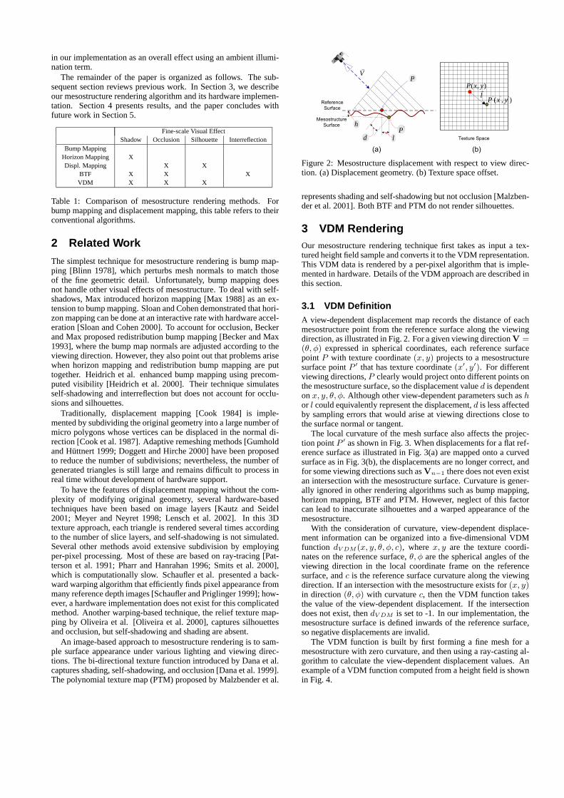
Figure 2: Mesostructure displacement with respect to view direc-tion. (a) Displacement geometry. (b) Texture space offset.
represents shading and self-shadowing but not occlusion [Malzben-der et al. 2001]. Both BTF and PTM do not render silhouettes.
3 VDM RenderingOur mesostructure rendering technique first takes as input a tex-tured height field sample and converts it to the VDM representation.This VDM data is rendered by a per-pixel algorithm that is imple-mented in hardware. Details of the VDM approach are described inthis section.
3.1 VDM DefinitionA view-dependent displacement map records the distance of eachmesostructure point from the reference surface along the viewingdirection, as illustrated in Fig. 2. For a given viewing direction V =(θ, φ) expressed in spherical coordinates, each reference surfacepoint P with texture coordinate (x, y) projects to a mesostructuresurface point P ′ that has texture coordinate (x′, y′). For differentviewing directions, P clearly would project onto different points onthe mesostructure surface, so the displacement value d is dependenton x, y, θ, φ. Although other view-dependent parameters such as hor l could equivalently represent the displacement, d is less affectedby sampling errors that would arise at viewing directions close tothe surface normal or tangent.
The local curvature of the mesh surface also affects the projec-tion point P ′ as shown in Fig. 3. When displacements for a flat ref-erence surface as illustrated in Fig. 3(a) are mapped onto a curvedsurface as in Fig. 3(b), the displacements are no longer correct, andfor some viewing directions such as Vn−1 there does not even existan intersection with the mesostructure surface. Curvature is gener-ally ignored in other rendering algorithms such as bump mapping,horizon mapping, BTF and PTM. However, neglect of this factorcan lead to inaccurate silhouettes and a warped appearance of themesostructure.
With the consideration of curvature, view-dependent displace-ment information can be organized into a five-dimensional VDMfunction dV DM (x, y, θ, φ, c), where x, y are the texture coordi-nates on the reference surface, θ, φ are the spherical angles of theviewing direction in the local coordinate frame on the referencesurface, and c is the reference surface curvature along the viewingdirection. If an intersection with the mesostructure exists for (x, y)in direction (θ, φ) with curvature c, then the VDM function takesthe value of the view-dependent displacement. If the intersectiondoes not exist, then dV DM is set to -1. In our implementation, themesostructure surface is defined inwards of the reference surface,so negative displacements are invalid.
The VDM function is built by first forming a fine mesh for amesostructure with zero curvature, and then using a ray-casting al-gorithm to calculate the view-dependent displacement values. Anexample of a VDM function computed from a height field is shownin Fig. 4.

(a)
'0P
'1P
'2P
'1−nP
… ..
.
P
(b)
P
1V 0V
1−nV
2V…
...
'0P
1V 0V
1−nV
2V
… ..
.
'0P
'1P
'2P
'1−nP
… ...
Figure 3: View-dependent displacement variation for curved sur-faces.
While it is possible to compute the full 5D VDM by forminga mesostructure mesh for various curvature values, we in practicetake a less computationally expensive approach that is based on thezero-curvature mesostructure mesh. Details of this method are pre-sented in the Appendix.
3.2 Rendering AlgorithmAfter computing a VDM for a given mesostructure surface, it can bemapped to a new surface as a high-dimensional texture. This map-ping should result in texture coordinates on the object surface thathave locally uniform scale and little distortion, with the mesostruc-ture pattern closely maintained. Since the mesostructure is a 3Dvolume, it is also requisite that its dimensions be scaled equally inthe mapping.
To render this mapping, the normals of the object surface mustfirst be calculated from the height field. Each surface normal andthe two orthogonal directions of the texture define a local coordinatesystem in which the viewing and lighting directions are expressed.
The parameters of each pixel on the rasterized surface are thencomputed. These parameters consist of the texture coordinateT = (x, y), the illumination direction L = (θL, φL), the view-ing direction V = (θV , φV ), and the local curvatures cV , cL alongV and L respectively. From the two principal curvature directionsCmax, Cmin and their corresponding curvature values cmax, cmin,the curvature along the viewing direction V can be computed as
cV =cmax(V · Cmax)2 + cmin(V · Cmin)2
1 − (V · N)2.
The curvature cL along the lighting direction L is computed sim-ilarly. Since the cost of calculating the parameter values for eachpixel is unacceptably large, in practice we calculate the parametersper vertex and then interpolate them for each pixel.
After calculating these pixel quantities, VDM rendering of de-tailed geometry proceeds with the following four steps, organizedin the flowchart of Fig. 6.Silhouette Determination: The VDM function includes an explicitrepresentation of point visibility along the mesostructure silhouette.When dV DM = −1, then the corresponding line of sight intersectsno detailed geometry. In this case, the pixel need not be processedand the rest of the algorithm is skipped. In practice, for each pixelwe use its nearest sample value in texture space for silhouette de-termination.
(a) (b) (c) (d) (e)
Figure 4: VDM images synthesized from a mesostructure heightfield. (a) Height field, (b-e) VDM images for different viewing di-rections, where the gray-level is proportional to the view-dependentdisplacement from the bounding reference surface.
'PLθ
LθP ''PReference Surface
Mesostructure Surface
)tan( Lh θ⋅
Ld
)sec( L
hθ⋅
LightVv
Lv
h
Camera
Figure 5: Shadow determination in VDM
Real Texture Coordinate Calculation: Since properties of thedetailed geometry are parameterized by texture coordinates onthe planar reference surface, the actual texture coordinate of eachmesostructure intersection point needs to be determined.
For a planar reference surface, the offset between the real tex-ture coordinate T ′ and original texture coordinate T = (x, y)can be computed as dT = dV DM (x, y, θV , φV , cV )Vxy , whereVxy = (sinθV cosφV , sinθV sinφV ) is the projection of the view-ing vector onto the local tangent plane. For a curved reference sur-face, the texture offset can be computed in the same way from theextended VDM displacement for curved surfaces described in theAppendix.
The real texture coordinate T ′ is then obtained by adding thisoffset to the original texture coordinate T , i.e., T ′ = T + dT .Shadow Determination: Shadowing of the intersection point fromthe light source can be determined from the VDM function. We firstdescribe this computation for a flat surface as illustrated in Fig. 5.Let P be the mesh surface point and P ′ be the intersection pointon the detailed geometry. Let h denote the distance from P ′ to thesurface as given by the mesostructure height field. The point P ′′
represents the reference surface intersection of L passing throughP ′.
Since the surface is flat, the texture coordinate of P ′′ can begeometrically determined as T = T + h · tan(θL) · L. The view-dependent displacement of P ′′ = (x′′, y′′) along L is given bydL = dV DM (x′′, y′′, θL, φL, 0).
The distance h · sec(θL) between P ′ and P ′′ is compared to dL
to determine the presence of shadow. When the two quantities areequal, the light source is not occluded from P ′; otherwise, P ′ is inshadow.
For a curved object surface, the computation of T requires solv-ing some trigonometric equations. To reduce run-time computation,a table indexed by the variables h, θL and cL could be built. Wehave found, however, that the effect of curvature on shadow deter-mination is generally unnoticeable, so it is ignored in our imple-mentation.Pixel Shading: If the pixel is not in shadow, a pre-defined re-flectance model is used to compute pixel appearance. Otherwise,its appearance is computed for ambient illumination only.
3.3 Data Decomposition and CompressionThe rapid development of programmable graphics hardware pro-vides opportunities for real-time implementations of our VDM ren-dering algorithm. However, some hardware constraints should beovercome. First, the maximum dimensionality of texture maps incurrent hardware poses a problem for high-dimensional maps suchas VDM. Second, memory constraints present an obstacle to thesubstantial amount of VDM data. Throughout this paper, we usemesostructure height fields of resolution 128 × 128 with 32 × 8viewing directions and 16 curvatures. The corresponding 64 MB ofVDM data consumes most of the graphics hardware memory andcannot efficiently be loaded.
To deal with these restrictions, we decompose and compress thedata by singular-value decomposition (SVD). SVD has the benefit

Begin
Silhouette DeterminationYes
No
Real Texture Coordinate Calculation
Shadow DeterminationYesNo
Shading Computation Ambient Computation
End
Output Pixel Apperance
Figure 6: Flowchart of per-pixel VDM rendering.
that it can efficiently decompose a high-dimensional map into twolower-dimensional maps. Moreover, reconstruction is performedusing only linear arithmetic operations, which can easily be handledin the hardware. For data with high correlation, a small number ofeigen-functions is sufficient for good reconstruction.
In VDM, when a ray along a view direction has no intersectionwith the mesostructure, it is labelled with the special value −1.When the silhouette exhibits high frequency, the number of eigenfunctions needed for acceptable reconstruction is dramatically in-creased, which leads to difficulties in hardware implementation.
To address this problem, we employ an auxiliary 4D MaximalView polar angle Map (MVM). For a densely sampled VDM, theMVM θMV M (x, y, φ, c) ≡ max θ such that
dV DM (x, y, θ, φ, c) �= −1,
where x, y are texture coordinates, φ is the azimuth angle of theviewing direction, and c is the local curvature. After this compu-tation, the -1 value of the corresponding polar viewing angle in theoriginal VDM is then replaced with this maximum polar viewingangle. For our mesostructure samples, the MVM size is 4 MB, andcombined with the VDM data, the total data size becomes 68 MB.
The high-dimensional VDM and MVM are then reorganized intoa 2D matrix
A = [AV DM , AMV M ]
such that the rows are indexed by x, y, φ and the columns are in-dexed by θ and/or c. Although these maps could be differentlyorganized for decomposition, experiments have shown that our so-lution provides the best compromise between accuracy and storagefor all data used in this paper.
Applying SVD to A gives A = UλET = WET , where E =[EV DM , EMV M ] contains the eigen functions of A and W = Uλcontains the weights of the eigen functions. From this, the two mapscan be expressed as
dV DM (x, y, θ, φ, c) =∑
i
W i(x, y, φ)EiV DM (θ, c)
θMV M (x, y, φ, c) =∑
i
W i(x, y, φ)EiMV M (c)
where i indexes the eigen functions in E and the eigen functionweights in W . Note that a common weight function is used for thetwo maps to reduce storage.
Since the eigenvalues decrease rapidly in magnitude, good ren-dering accuracy can be achieved with a small number of eigen func-tions. For the VDM data used in this paper, we employ only 8 VDMand 4 MVM eigen functions for rendering. By this decompositionand compression, the original 68 MB of VDM is reduced to 4 MB.
(b)(a) (c)
Figure 7: Mesh complexity in VDM and displacement mappingfor rendering similar level of detail images. (a) VDM mesh, (b)Displacement map mesh. (c) Zoomed views of the green and redboxes in (a) and (b) respectively.
4 ResultsOur system is implemented on a 1.4 GHz 768MB Pentium IV PCwith an ATI Radeon 9700 Pro 128MB graphics card. The hardware-accelerated VDM rendering is implemented as a single renderingpass using Pixel Shader 2.0 with OpenGL. The complexity of thepixel shader is 40 arithmetic instructions and 14 texture lookups.All VDM data in this paper is of resolution 128x128 and sampledfor 32x8 viewing directions and 16 curvatures between −2.0 and3.0, which are interpolated for intermediate values. The number ofsampled values can be increased for greater accuracy at the expenseof data size. Additionally, VDM as a texture map is easily anti-aliased by mip-mapping all data dimensions.
Important visual effects such as shadowing, occlusion, and sil-houettes are all captured well by the VDM technique. Fig. 1compares VDM with hardware-accelerated bump mapping, horizonmapping and conventional displacement mapping where the geom-etry is subdivided and displaced before software rendering.1 Theadded mesh complexity of displacement mapping as exemplified inFig. 7 prevents rendering in real time.
Overall, the VDM algorithm has a fill rate performance of ap-proximately 50M/sec and a per-triangle processing speed of about15M/sec. A main reason for the real-time performance of VDMis that it is based on per-pixel processing. Additional examples ofVDM rendering are displayed in Fig. 9. These models have a screensize of 512 × 512 and rendering performance listed in the figure.
Renderings under different levels of data compression are dis-played in Fig 8. It can be seen that even with only a small numberof eigen functions, the mesostructure maintains an appearance closeto that for the original uncompressed VDM.
5 ConclusionIn this paper, we presented a pixel-based method for real-time ren-dering of surface mesostructure and its associated visual effects,including shadowing, occlusion, and silhouettes. A number of re-search topics remain to be explored. We plan to investigate meth-ods for efficient capture of VDM functions from real world sur-faces. Also, VDMs will be extended to model open surface bound-aries, which are not handled in our current implementation. An-other interesting topic is to incorporate interreflections and supportspatially-variant BRDFs in the VDM framework.
Acknowledgments: We would like to thank the anonymous re-viewers for their constructive critiques. Many thanks to Jeff Royle
1Currently, adaptive tessellated displacement mapping is supported onlyby the Matrox Parhelia, but information such as source code, API supportand a proper driver are not available. ATI claims to support pre-sampleddisplacement mapping on the Radeon9700. However, our personal commu-nications with ATI technical staff revealed that no proper driver is availablenow to access this feature.
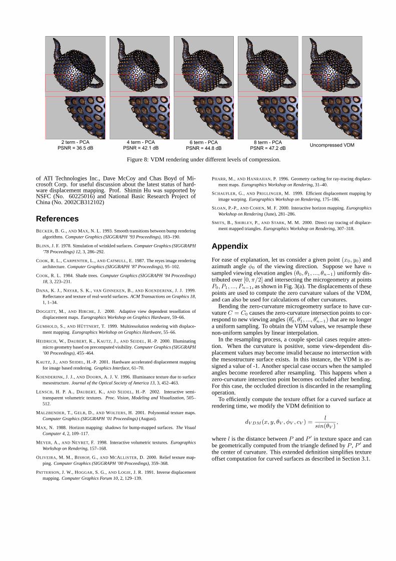
2 term - PCAPSNR = 36.5 dB
4 term - PCAPSNR = 42.1 dB
6 term - PCAPSNR = 44.8 dB
8 term - PCAPSNR = 47.2 dB
Uncompressed VDM
Figure 8: VDM rendering under different levels of compression.
of ATI Technologies Inc., Dave McCoy and Chas Boyd of Mi-crosoft Corp. for useful discussion about the latest status of hard-ware displacement mapping. Prof. Shimin Hu was supported byNSFC (No. 60225016) and National Basic Research Project ofChina (No. 2002CB312102)
ReferencesBECKER, B. G., AND MAX, N. L. 1993. Smooth transitions between bump rendering
algorithms. Computer Graphics (SIGGRAPH ’93 Proceedings), 183–190.
BLINN, J. F. 1978. Simulation of wrinkled surfaces. Computer Graphics (SIGGRAPH’78 Proceedings) 12, 3, 286–292.
COOK, R. L., CARPENTER, L., AND CATMULL, E. 1987. The reyes image renderingarchitecture. Computer Graphics (SIGGRAPH ’87 Proceedings), 95–102.
COOK, R. L. 1984. Shade trees. Computer Graphics (SIGGRAPH ’84 Proceedings)18, 3, 223–231.
DANA, K. J., NAYAR, S. K., VAN GINNEKEN, B., AND KOENDERINK, J. J. 1999.Reflectance and texture of real-world surfaces. ACM Transactions on Graphics 18,1, 1–34.
DOGGETT, M., AND HIRCHE, J. 2000. Adaptive view dependent tessellation ofdisplacement maps. Eurographics Workshop on Graphics Hardware, 59–66.
GUMHOLD, S., AND HUTTNERT, T. 1999. Multiresolution rendering with displace-ment mapping. Eurographics Workshop on Graphics Hardware, 55–66.
HEIDRICH, W., DAUBERT, K., KAUTZ, J., AND SEIDEL, H.-P. 2000. Illuminatingmicro geometry based on precomputed visibility. Computer Graphics (SIGGRAPH’00 Proceedings), 455–464.
KAUTZ, J., AND SEIDEL, H.-P. 2001. Hardware accelerated displacement mappingfor image based rendering. Graphics Interface, 61–70.
KOENDERINK, J. J., AND DOORN, A. J. V. 1996. Illuminance texture due to surfacemesostructure. Journal of the Optical Society of America 13, 3, 452–463.
LENSCH, H. P. A., DAUBERT, K., AND SEIDEL, H.-P. 2002. Interactive semi-transparent volumetric textures. Proc. Vision, Modeling and Visualization, 505–512.
MALZBENDER, T., GELB, D., AND WOLTERS, H. 2001. Polynomial texture maps.Computer Graphics (SIGGRAPH ’01 Proceedings) (August).
MAX, N. 1988. Horizon mapping: shadows for bump-mapped surfaces. The VisualComputer 4, 2, 109–117.
MEYER, A., AND NEYRET, F. 1998. Interactive volumetric textures. EurographicsWorkshop on Rendering, 157–168.
OLIVEIRA, M. M., BISHOP, G., AND MCALLISTER, D. 2000. Relief texture map-ping. Computer Graphics (SIGGRAPH ’00 Proceedings), 359–368.
PATTERSON, J. W., HOGGAR, S. G., AND LOGIE, J. R. 1991. Inverse displacementmapping. Computer Graphics Forum 10, 2, 129–139.
PHARR, M., AND HANRAHAN, P. 1996. Geometry caching for ray-tracing displace-ment maps. Eurographics Workshop on Rendering, 31–40.
SCHAUFLER, G., AND PRIGLINGER, M. 1999. Efficient displacement mapping byimage warping. Eurographics Workshop on Rendering, 175–186.
SLOAN, P.-P., AND COHEN, M. F. 2000. Interactive horizon mapping. EurographicsWorkshop on Rendering (June), 281–286.
SMITS, B., SHIRLEY, P., AND STARK, M. M. 2000. Direct ray tracing of displace-ment mapped triangles. Eurographics Workshop on Rendering, 307–318.
Appendix
For ease of explanation, let us consider a given point (x0, y0) andazimuth angle φ0 of the viewing direction. Suppose we have nsampled viewing elevation angles (θ0, θ1, ..., θn−1) uniformly dis-tributed over [0, π/2] and intersecting the microgeometry at pointsP0, P1, ..., Pn−1, as shown in Fig. 3(a). The displacements of thesepoints are used to compute the zero curvature values of the VDM,and can also be used for calculations of other curvatures.
Bending the zero-curvature microgeometry surface to have cur-vature C = C0 causes the zero-curvature intersection points to cor-respond to new viewing angles (θ′
0, θ′1, ..., θ
′n−1) that are no longer
a uniform sampling. To obtain the VDM values, we resample thesenon-uniform samples by linear interpolation.
In the resampling process, a couple special cases require atten-tion. When the curvature is positive, some view-dependent dis-placement values may become invalid because no intersection withthe mesostructure surface exists. In this instance, the VDM is as-signed a value of -1. Another special case occurs when the sampledangles become reordered after resampling. This happens when azero-curvature intersection point becomes occluded after bending.For this case, the occluded direction is discarded in the resamplingoperation.
To efficiently compute the texture offset for a curved surface atrendering time, we modify the VDM definition to
dV DM (x, y, θV , φV , cV ) =l
sin(θV ),
where l is the distance between P and P ′ in texture space and canbe geometrically computed from the triangle defined by P , P ′ andthe center of curvature. This extended definition simplifies textureoffset computation for curved surfaces as described in Section 3.1.
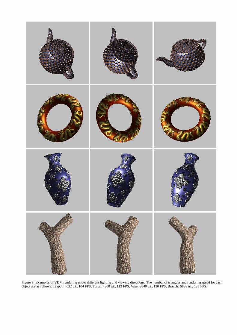
Figure 9: Examples of VDM rendering under different lighting and viewing directions. The number of triangles and rendering speed for eachobject are as follows. Teapot: 4032 tri., 104 FPS; Torus: 4800 tri., 112 FPS; Vase: 8640 tri., 130 FPS; Branch: 5888 tri., 139 FPS.


![Analytic Displacement Mapping using Hardware Tessellation › papers › 2013 › 3analytic › ... · Analytic Displacement Mapping using Hardware Tessellation 3 Ray et al. [2010]](https://img.pdfslide.us/doc/110x75/5f03e70c7e708231d40b5591/analytic-displacement-mapping-using-hardware-tessellation-a-papers-a-2013-a.jpg)