Embed Size (px)
Citation preview
Please read this manual before operating your fusion splicer, and keep it for future reference.
2014/11 Rev.0.1
ARC Fusion SplicerView 7 User Manual

1
View 7User Manual

2

3
Contents
Introduction
Chapter 1: Technical specifications
Applicable fiber type
Splice loss
Splice mode
Heat oven
Power supply
Dimensions and weight
Environment
Other
Battery precautions
Chapter 2: Installation
Safety warnings and precautions
Operational safety warnings
Maintenance and external care precautions
Transport and storage precautions
Installation
Unpacking the splicer
Splicer overview
Power supply
Battery
Charge the battery
How to check remaining battery capacity
Battery refresh
Chapter 3: Basic Operation
Turning on the splicer
Adjusting the monitor position
Adjusting the monitor brightness
7
8
8
8
8
8
9
9
9
9
10
11
11
11
12
13
14
14
16
17
17
17
18
18
19
19
19
20
Contents 4
Touch screen On/Off
Fiber zoom function on screen
Preparing the fibers
How to make a splice
Placing the fibers
Inspecting the fibers
Splicing
How to protect the splice
Heating procedure
Chapter 4: Splice Programs
Displaying the active splice program
Selecting a splice program
General splicing steps
Pre-fusion
Fusion
Splicing process
Splice program parameters under general splicing process
Chapter 5: Splice Option
Setting up splice mode
Chapter 6: Heater Mode
Selecting heater mode
Editing heater mode
Deleting heater mode
Heater mode parameters
Chapter 7: Maintenance Menu
Replace electrodes
Replacement procedure
Stabilize electrodes
Operation procedure
Diagnostic test
20
21
21
22
22
22
23
24
24
25
25
26
27
27
27
27
28
30
30
32
32
33
34
34
35
35
35
36
36
36
Contents 5
Operation procedure
Dust check
Operation procedure
Motor calibration
Operation procedure
Arc calibration
Operation procedure
Electrode setting
Update software
Chapter 8: Other Functions & Utilities
Data storage
Display splice record
Delete splice record
Cancel data storage
System setting
Monitor position
Power save option
System information
Appendix I: Reasons for high splice loss and solutions
Appendix II: List of error messages
Appendix III: Frequent questions and troubleshooting
36
37
37
37
38
38
38
39
39
40
40
40
40
40
41
42
43
43
44
46
49
6
Important: INNO Instrument strongly recommends all users to read this manual
before operating VIEW 7.
This manual is valid for the following software version:

7
Introduction
Thank you for choosing VIEW 7 Arc Fusion Splicer from INNO Instrument. View 7
adopts innovative product design and exquisite manufacturing technology so as to
deliver unprecedented splicing experience to customers.The totally new
technology greatly reduces splicing and heating time, and advanced estimation
method and alignment technique ensure the accuracy of splice loss estimation.
The simple-but-trendy product design, sophisticated internal structure and reliable
protective cover make the splicer be suitable for any operating environment.
Dynamic operation interface and automatic splice mode provide users great
convenience. For more information of VIEW 7, please visit our official website at
www.innoinstrument.com
8
Technical Specifications
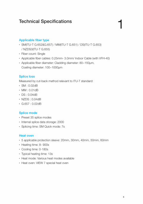
Applicable fiber type• SM(ITU-T G.652&G.657) / MM(ITU-T G.651) / DS(ITU-T G.653)
/ NZDS3(ITU-T G.655)• Fiber count: Single• Applicable fiber cables: 0.25mm- 3.0mm/ Indoor Cable (with VFH-40)• Applicable fiber diameter: Cladding diameter: 80~150μm,
Coating diameter: 100~1000μm
Splice lossMeasured by cut-back method relevant to ITU-T standard:• SM : 0.02dB• MM : 0.01dB• DS : 0.04dB• NZDS : 0.04dB• G.657 : 0.02dB
Splice mode• Preset 35 splice modes• Internal splice data storage: 2000• Splicing time: SM Quick mode: 7s
Heat oven• 5 applicable protection sleeve: 20mm, 30mm, 40mm, 50mm, 60mm• Heating time: 8- 900s• Cooling time: 0-180s• Typical heating time: 13s• Heat mode: Various heat modes available• Heat oven: VIEW 7 special heat oven
1

Chapter 1 Technical Specifications 9
Power supply• Standard AC power voltage: AC 100-240V, 50-60Hz• Standard DC power voltage: DC 9-14V
Dimensions and weight• Size: Height x Width X Depth = 167mm x 143mm x 163mm• Weight: 2.80kg (battery included)
Environment• Operating condition: 0~5000m above sea level, 0~95% relative humidity,
-10~50℃, 15m/s max wind speed• Storage condition: 0~95% relative humidity, -40~80℃• Battery: -20~30℃ for long time storage
Other• Viewing and displaying method: two cameras and 5.0 inch color LCD monitor• 520x magnification for single X or Y view, or 520x magnification for
both X and Y view.• Tensile test: 1.96-2.25N• Terminals: USB2.0 / MINI USB
Chapter 1 Technical Specifications 10
Battery precautions• DO NOT collide the battery with sharp or hard objects.• DO NOT transport or store the battery with metals simultaneously.• DO NOT throw, drop, impact or bend the battery.• DO NOT strike the battery with hammers or tread on it.• DO NOT connect the anode and cathode of the battery to metals such as
electrical short circuit.• DO NOT let the anode and cathode contact with the external aluminum coating
of the battery so as to avoid short circuit.• DO NOT disassemble the battery under any circumstances.• DO NOT immerse the battery in fresh water or sea water, and avoid moisture.• DO NOT use or place the battery near heat source. (e.g. fire, heat oven)• DO NOT heat the battery or throw it into water.• DO NOT weld the battery directly.• DO NOT charge the battery near fire or in high temperature.• DO NOT put the battery into the microwave oven or high pressure container.• DO NOT use or place the battery in extremely high temperature
(e.g. strong sunlight or inside a car which is with poor ventilation) for long period
of time. Otherwise, it may cause overheat, fire, battery malfunction, or shorter
battery life.• DO NOT use damaged battery. The battery with electrolyte leakage or electrolyte
smell shall be kept away from fire to avoid fire or explosion.• If electrolyte leakage contacts with skin or other parts of body, please wash it off
with a plenty of water immediately. If electrolyte leakage contacts with your
eye(s), please rinse your eye(s) with water immediately and seek medical advice.
11
2Installation
Safety warnings and precautionsAs VIEW 7 is designed for fusion splicing silica glass optical fibers, it is very
important that the splicer should not be used for any other purposes. The splicer
is a precision instrument and must be handled with caution. Therefore, you must
read the following safety rules and general precautions in this manual regarding the
use and handling of VIEW 7 at any time. Any behaviors that do not follow the
warnings and cautions will break the safety standard about design, manufacture,
and usage of the fusion splicer. INNO Instrument will not take the responsibility for
those consequences caused by misuse!
Operational safety warnings• Never operate the splicer in an environment where flammable liquids or vapors
exist.• DO NOT touch the electrodes when the splicer is on.
Note: Only use specified electrodes for the fusion splicer. Select [Replace
electrode] in maintenance menu to replace electrodes, or turn off the splicer and
disconnect the AC power source or remove battery before replacing electrodes.
Discharging is prohibited before the electrodes are placed as a pair.
• DO NOT disassemble or modify any components of the splicer without approval,
except for the permitted-to-disassemble / modify components or parts by users
stated in this manual. Component replacement and its internal adjustment must
be implemented by INNO Instrument or its authorized technicians or engineers. • Never operate the splicer in an environment where flammable liquids or vapors
exist. Risk of dangerous fire or explosion could result from the splicer’s electrical
arc in such an environment. DO NOT operate the splicer near hot objects or in
high temperature and dusty / humid atmosphere, or when condensation is
present on the splicer. This may result in electric shock, splicer malfunction,
or poor splicing performance.
Chapter 2 Installation 12
• Users should always wear safety glasses during fiber preparation and splicing
operation. Fiber fragments can be extremely dangerous if they are ingested or
come into contact with eyes, skin.• Take out the battery immediately if the followings are observed when using
the splicer:• Fumes, bad smell, abnormal noise or over heat.• Liquid or other matter falls into cabinet• The splicer is damaged or dropped.
Note: If any of these faults occurs, please contact our service center
immediately. Leaving the splicer in a damaged state without any prompt
measures may cause equipment failure, electric shock, or fire and may result in
injury or death.
• Do not use compressed gas or canned air to clean the splicer. They may contain
flammable materials that could ignite during the electrical discharge.• Please use VIEW 7 designed battery only. Using an improper AC power source
may cause fuming, electric shock or equipment damage and may even result in
fire, injury or death.• Please use VIEW 7 designed charger only. Do not place any heavy objects on
the AC power cord. Keep the power cord away from heat source. Using an
improper cord or a damaged cord may cause fuming, electric shock or
equipment damage and may even result in fire, injury or death.
Maintenance and external care precautions• Always avoid using hard objects to clean V-grooves and electrodes.• Always avoid using acetone, thinner, benzol or alcohol when cleaning any parts
of the splicer, except for the places advised.• Use a dry cloth to remove dust and dirt from the splicer.• If the outside of the splicer is dirty, plunge a soft cloth into diluted neutral
washing up liquid, wring out the cloth and clean. Dry the splicer with a dry cloth
but DO NOT USE furniture polish or other cleaning agents.• Always follow the maintenance instructions in this manual.

Chapter 2 Installation 13
Transport and storage precautions• When the splicer is moved from cold to warm environment, you should allow the
splicer to warm up gradually. Otherwise, the condensation generated inside will
bring harmful effects to the splicer.• Pack the fusion splicer well for long time storage.• Keep the splicer clean and dry.• The splicer is precision adjusted and aligned. Always keep the splicer in its
carrying case to protect from damage and dirt. Put cushion package outside the
carrying case for long distance transportation.• Always avoid leaving the splicer in direct sunlight or expose to excessive heat.• DO NOT store the splicer in dusty or humid environment. This may result in
electric shock, splicer malfunction or poor splicing performance.• Keep the humidity to a minimum level where the splicer is stored. The humidity
must not exceed 95%.
Chapter 2 Installation 14
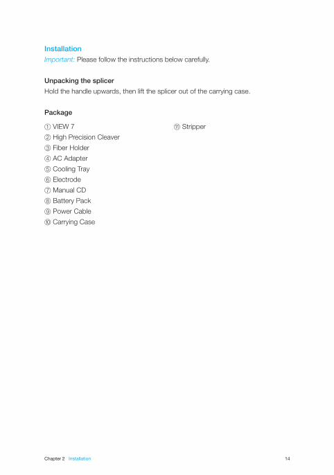
InstallationImportant: Please follow the instructions below carefully.
Unpacking the splicer
Hold the handle upwards, then lift the splicer out of the carrying case.
Package
⑪ Stripper① VIEW 7
② High Precision Cleaver
③ Fiber Holder
④ AC Adapter
⑤ Cooling Tray
⑥ Electrode
⑦ Manual CD
⑧ Battery Pack
⑨ Power Cable
⑩ Carrying Case
Chapter 2 Installation 15
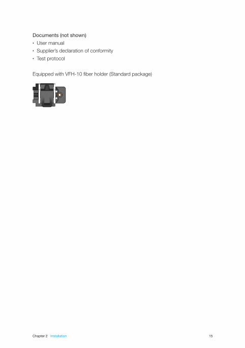
Documents (not shown)• User manual• Supplier’s declaration of conformity• Test protocol
Equipped with VFH-10 fiber holder (Standard package)
Chapter 2 Installation 16
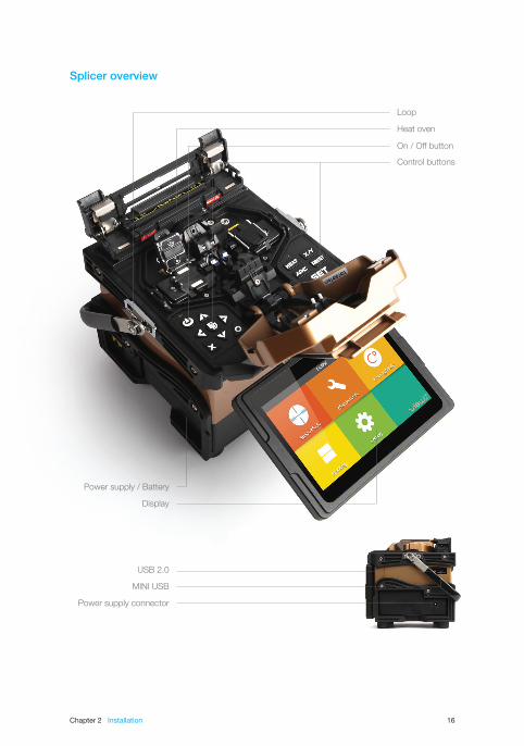
Heat oven
USB 2.0
MINI USB
Power supply connector
Display
Power supply / Battery
Loop
On / Off button
Control buttons
Splicer overview

Chapter 2 Installation 17
Insert the battery into the power unit dock until it clicks into place.
Insert
Release button
Take out the battery
Step 1 Step 2
Power supplyBattery
Switch off the splicer. Press the [Release] button at the side of the splicer and take
out the battery from the splicer.
Charge the battery
Connect the battery charger to the battery.
Charging progress is indicated by five lit LEDs continuously sweeping from 20% to
100% on the battery indicator (see below).
As charging proceeds, one LED is lit when 20% charged. When it’s fully charged,
all five LEDs are lit (i.e. 100%).
Chapter 2 Installation 18
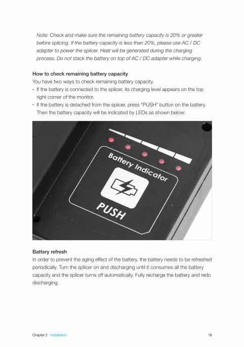
Note: Check and make sure the remaining battery capacity is 20% or greater
before splicing. If the battery capacity is less than 20%, please use AC / DC
adapter to power the splicer. Heat will be generated during the charging
process. Do not stack the battery on top of AC / DC adapter while charging.
How to check remaining battery capacity
You have two ways to check remaining battery capacity.• If the battery is connected to the splicer, its charging level appears on the top
right corner of the monitor.• If the battery is detached from the splicer, press “PUSH” button on the battery.
Then the battery capacity will be indicated by LEDs as shown below:
Battery refresh
In order to prevent the aging effect of the battery, the battery needs to be refreshed
periodically. Turn the splicer on and discharging until it consumes all the battery
capacity and the splicer turns off automatically. Fully recharge the battery and redo
discharging.
19
Basic Operation
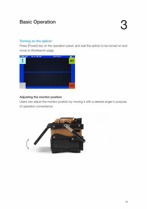
Turning on the splicerPress [Power] key on the operation panel, and wait the splicer to be turned on and
move to Workbench page.
Adjusting the monitor position
Users can adjust the monitor position by moving it with a desired angle in purpose
of operation convenience.
3
Chapter 3 Basic Operation 20
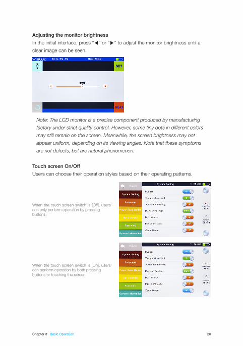
Adjusting the monitor brightness
In the initial interface, press “◀” or “▶” to adjust the monitor brightness until a
clear image can be seen.
Note: The LCD monitor is a precise component produced by manufacturing
factory under strict quality control. However, some tiny dots in different colors
may still remain on the screen. Meanwhile, the screen brightness may not
appear uniform, depending on its viewing angles. Note that these symptoms
are not defects, but are natural phenomenon.
Touch screen On/Off
Users can choose their operation styles based on their operating patterns.
When the touch screen switch is [Off], users can only perform operation by pressing buttons.
When the touch screen switch is [On], users can perform operation by both pressing buttons or touching the screen.
Chapter 3 Basic Operation 21
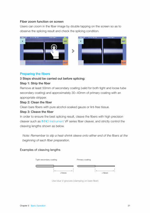
Fiber zoom function on screen
Users can zoom in the fiber image by double tapping on the screen so as to
observe the splicing result and check the splicing condition.
Preparing the fibers3 Steps should be carried out before splicing:
Step 1: Strip the fiber
Remove at least 50mm of secondary coating (valid for both tight and loose tube
secondary coating) and approximately 30~40mm of primary coating with an
appropriate stripper.
Step 2: Clean the fiber
Clean bare fibers with pure alcohol-soaked gauze or lint-free tissue.
Step 3: Cleave the fiber
In order to ensure the best splicing result, cleave the fibers with high precision
cleaver such as INNO Instrument VF series fiber cleaver, and strictly control the
cleaving lengths shown as below.
Note: Remember to slip a heat-shrink sleeve onto either end of the fibers at the
beginning of each fiber preparation.
Examples of cleaving lengths
10 10
Use blue V-grooves (clamping on bare fiber)
Primary coatingTight secondary coating
Chapter 3 Basic Operation 22
Important: Make sure that the bare fiber and its cleaved section are clean.• Avoid putting the fibers on a dusty working surface.
• Avoid swaying the fibers in the air.
• Check if the V-grooves are clean. If not, must clean it with pure alcohol-soaked
cotton swabs.
• Check if the fiber holders are clean. If not, must clean it with pure alcohol-soaked
cotton swabs.
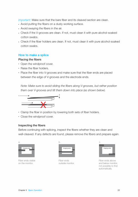
How to make a splicePlacing the fibers• Open the windproof cover.• Raise the fiber holders.• Place the fiber into V-grooves and make sure that the fiber ends are placed
between the edge of V-grooves and the electrode ends.
Note: Make sure to avoid sliding the fibers along V-grooves, but rather position
them over V-grooves and tilt them down into place (as shown below).
• Clamp the fiber in position by lowering both sets of fiber holders.• Close the windproof cover.
Inspecting the fibers
Before continuing with splicing, inspect the fibers whether they are clean and
well-cleaved. If any defects are found, please remove the fibers and prepare again.
Fiber ends visible on the monitor.
Fiber ends outside monitor.
Fiber ends aboveand below monitor,not possible to findautomatically.
a. b. c.
Chapter 3 Basic Operation 23
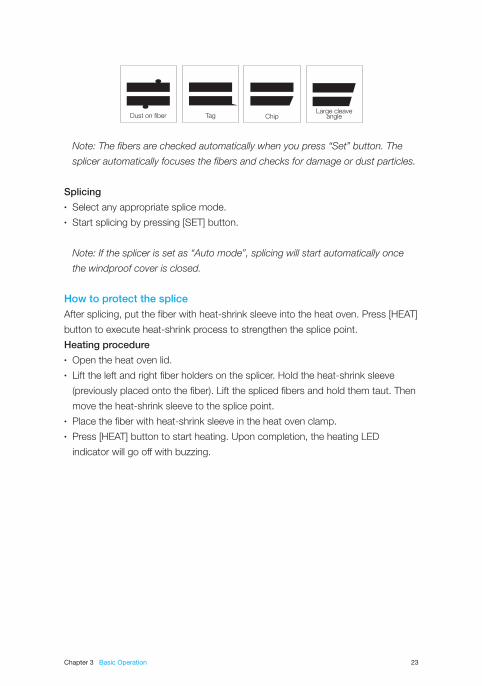
Note: The fibers are checked automatically when you press “Set” button. The
splicer automatically focuses the fibers and checks for damage or dust particles.
Splicing• Select any appropriate splice mode.• Start splicing by pressing [SET] button.
Note: If the splicer is set as “Auto mode”, splicing will start automatically once
the windproof cover is closed.
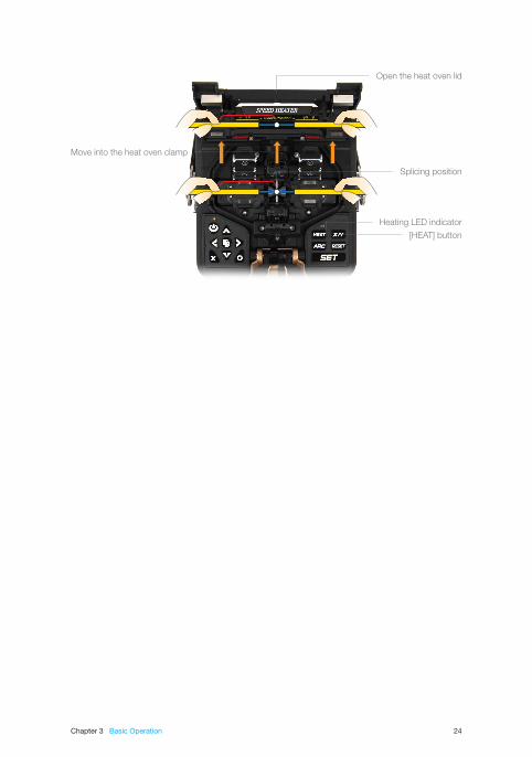
How to protect the spliceAfter splicing, put the fiber with heat-shrink sleeve into the heat oven. Press [HEAT]
button to execute heat-shrink process to strengthen the splice point.
Heating procedure• Open the heat oven lid.• Lift the left and right fiber holders on the splicer. Hold the heat-shrink sleeve
(previously placed onto the fiber). Lift the spliced fibers and hold them taut. Then
move the heat-shrink sleeve to the splice point.• Place the fiber with heat-shrink sleeve in the heat oven clamp.• Press [HEAT] button to start heating. Upon completion, the heating LED
indicator will go off with buzzing.
Dust on fiber ChipTagLarge cleave
angle
Chapter 3 Basic Operation 24
Open the heat oven lid
Move into the heat oven clamp
Splicing position
Heating LED indicator
[HEAT] button
25
Splice Programs
VIEW 7 has an intuitive and simple but very powerful program structure to operate.
Splice programs define arc currents, splice times as well as various parameters
used when performing a splice. Therefore, it is essential to select the correct splice
program. There are a number of “preset” splice programs for common fiber
combinations. Therefore, it is much easier to modify and further optimize the
parameters for more unusual fiber combinations.
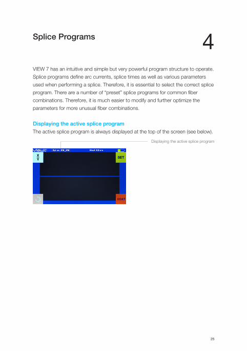
Displaying the active splice programThe active splice program is always displayed at the top of the screen (see below).
4
Displaying the active splice program
Chapter 4 Splice Programs 26
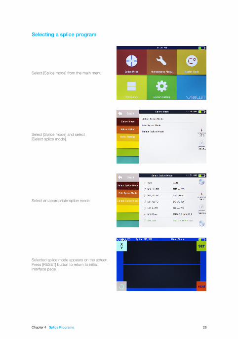
Selecting a splice program
Select [Splice mode] from the main menu.
Select [Splice mode] and select [Select splice mode].
Select an appropriate splice mode
Selected splice mode appears on the screen. Press [RESET] button to return to initial interface page.
Chapter 4 Splice Programs 27
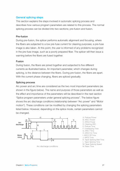
Arc discharge conditions
General splicing stepsThis section explains the steps involved in automatic splicing process and
describes how various program parameters are related to this process. The normal
splicing process can be divided into two sections; pre-fusion and fusion.
Pre-fusion
During pre-fusion, the splicer performs automatic alignment and focusing, where
the fibers are subjected to a low pre-fuse current for cleaning purposes; a pre-fuse
image is also taken. At this point, the user is informed of any problems recognized
in the pre-fuse image, such as a poorly prepared fiber. The splicer will then issue a
warning before the fibers are fused together.
Fusion
During fusion, the fibers are joined together and subjected to five different
currents as illustrated below. An important parameter, which changes during
splicing, is the distance between the fibers. During pre-fusion, the fibers are apart.
With the current phase changing, fibers are spliced gradually.
Splicing process
Arc power and arc time are considered as the two most important parameters (as
shown in the figure below). The name and purpose of those parameters as well as
the effect and importance of the parameters will be described in the next section
“Splice program parameters under general splicing process”. The below figure
shows the arc discharge conditions (relationship between “Arc power” and “Motor
motion”). These conditions can be modified by changing the splicing parameters
listed below. However, depending on the splice mode, certain parameters cannot
be changed.
A: Prefuse PowerB: ARC1 PowerC: ARC2 PowerD: Cleaning ARCE: Prefuse TimeF: Overlapping TimeG: ARC1 TimeH: ARC2 On TimeI: ARC2 Off TimeJ: ARC2 TimeK: Taper Splicing Wait TimeL: Taper Splicing TimeM: Taper Splicing SpeedN: Rearc Time
Chapter 4 Splice Programs 28
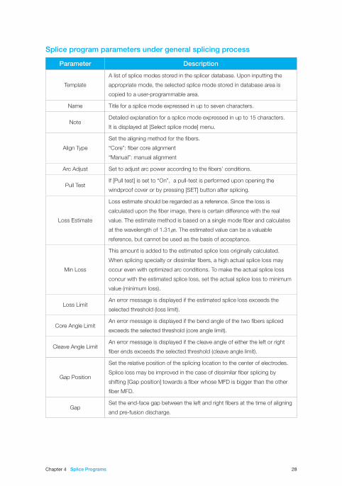
Splice program parameters under general splicing process
Parameter Description
Template
A list of splice modes stored in the splicer database. Upon inputting the
appropriate mode, the selected splice mode stored in database area is
copied to a user-programmable area.
Name Title for a splice mode expressed in up to seven characters.
NoteDetailed explanation for a splice mode expressed in up to 15 characters.
It is displayed at [Select splice mode] menu.
Align Type
Set the aligning method for the fibers.
“Core”: fiber core alignment
“Manual”: manual alignment
Arc Adjust Set to adjust arc power according to the fibers’ conditions.
Pull TestIf [Pull test] is set to “On”, a pull-test is performed upon opening the
windproof cover or by pressing [SET] button after splicing.
Loss Estimate
Loss estimate should be regarded as a reference. Since the loss is
calculated upon the fiber image, there is certain difference with the real
value. The estimate method is based on a single mode fiber and calculates
at the wavelength of 1.31㎛. The estimated value can be a valuable
reference, but cannot be used as the basis of acceptance.
Min Loss
This amount is added to the estimated splice loss originally calculated.
When splicing specialty or dissimilar fibers, a high actual splice loss may
occur even with optimized arc conditions. To make the actual splice loss
concur with the estimated splice loss, set the actual splice loss to minimum
value (minimum loss).
Loss LimitAn error message is displayed if the estimated splice loss exceeds the
selected threshold (loss limit).
Core Angle LimitAn error message is displayed if the bend angle of the two fibers spliced
exceeds the selected threshold (core angle limit).
Cleave Angle LimitAn error message is displayed if the cleave angle of either the left or right
fiber ends exceeds the selected threshold (cleave angle limit).
Gap Position
Set the relative position of the splicing location to the center of electrodes.
Splice loss may be improved in the case of dissimilar fiber splicing by
shifting [Gap position] towards a fiber whose MFD is bigger than the other
fiber MFD.
GapSet the end-face gap between the left and right fibers at the time of aligning
and pre-fusion discharge.

Chapter 4 Splice Programs 29
Overlap
Set the overlap amount of fibers at the fiber propelling stage. Relatively
small [Overlap] is recommended if [Preheat Arc Value] is low, while relatively
large [Overlap] is recommended if [Preheat Arc Value] is high.
Clean Arc Time
A cleaning arc burns out micro dust on the surface of the fiber with an arc
discharge for a short period of time. The duration of the cleaning arc can be
changed by this parameter.
Preheat Arc Value
Set the prefuse arc power from the beginning of arc discharging to the
beginning of fibers propelling. If [Preheat Arc Value] is set too low, axial
offset may occur if cleaved angles are relatively poor. If [Preheat Arc Value]
is set too high, fiber end-faces are fused excessively and splice loss gets
worse.
Preheat Arc Time
Set the prefuse arc time from the beginning of arc discharging to the
beginning of fibers propelling. Long [Preheat Arc Time] and high
[Preheat Arc Value] lead to the same results.
Fuse Arc Value Set arc power.
Fuse Arc Time Sets arc time.
30
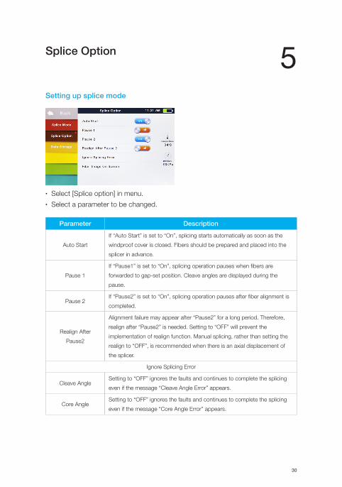
Splice Option
Setting up splice mode
• Select [Splice option] in menu.• Select a parameter to be changed.
5
Parameter Description
Auto Start
If “Auto Start” is set to “On”, splicing starts automatically as soon as the
windproof cover is closed. Fibers should be prepared and placed into the
splicer in advance.
Pause 1
If “Pause1” is set to “On”, splicing operation pauses when fibers are
forwarded to gap-set position. Cleave angles are displayed during the
pause.
Pause 2If “Pause2” is set to “On”, splicing operation pauses after fiber alignment is
completed.
Realign After
Pause2
Alignment failure may appear after “Pause2” for a long period. Therefore,
realign after “Pause2” is needed. Setting to “OFF” will prevent the
implementation of realign function. Manual splicing, rather than setting the
realign to “OFF”, is recommended when there is an axial displacement of
the splicer.
Ignore Splicing Error
Cleave AngleSetting to “OFF” ignores the faults and continues to complete the splicing
even if the message “Cleave Angle Error” appears.
Core AngleSetting to “OFF” ignores the faults and continues to complete the splicing
even if the message “Core Angle Error” appears.

Chapter 5 Splice Option 31
Loss Setting to “OFF” ignores the faults and continues to complete the splicing
even if the message “Loss Error”, “Cleave Shape Error”, “Fat Error”, or “Thin
Error” appears.
Fat
Thin
Fiber Image On Screen
Gap Set
Set the displaying method of the fiber image on the screen during splicing
operation.
Pause1
Align
Pause2
Arc
Estimate
32
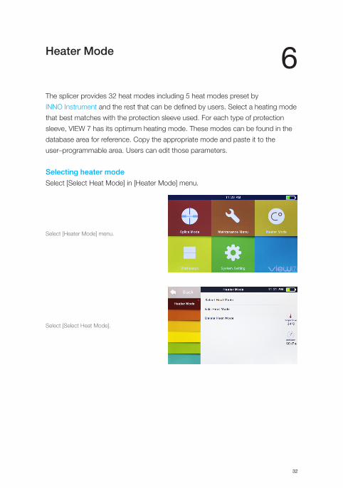
Heater Mode
The splicer provides 32 heat modes including 5 heat modes preset by
INNO Instrument and the rest that can be defined by users. Select a heating mode
that best matches with the protection sleeve used. For each type of protection
sleeve, VIEW 7 has its optimum heating mode. These modes can be found in the
database area for reference. Copy the appropriate mode and paste it to the
user–programmable area. Users can edit those parameters.
Selecting heater modeSelect [Select Heat Mode] in [Heater Mode] menu.
6
Select [Heater Mode] menu.
Select [Select Heat Mode].
Chapter 6 Heater Mode 33
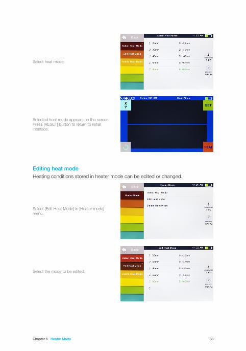
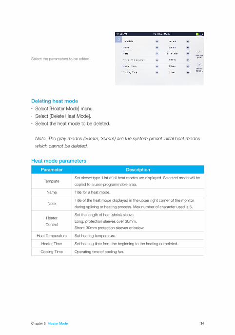
Editing heat modeHeating conditions stored in heater mode can be edited or changed.
Select [Edit Heat Mode] in [Heater mode] menu.
Select the mode to be edited.
Select heat mode.
Selected heat mode appears on the screen.Press [RESET] button to return to initial interface.
Chapter 6 Heater Mode 34
Deleting heat mode• Select [Heater Mode] menu.• Select [Delete Heat Mode].• Select the heat mode to be deleted.
Note: The gray modes (20mm, 30mm) are the system preset initial heat modes
which cannot be deleted.
Heat mode parameters
Parameter Description
TemplateSet sleeve type. List of all heat modes are displayed. Selected mode will be
copied to a user-programmable area.
Name Title for a heat mode.
NoteTitle of the heat mode displayed in the upper right corner of the monitor
during splicing or heating process. Max number of character used is 5.
Heater
Control
Set the length of heat-shrink sleeve.
Long: protection sleeves over 30mm.
Short: 30mm protection sleeves or below.
Heat Temperature Set heating temperature.
Heater Time Set heating time from the beginning to the heating completed.
Cooling Time Operating time of cooling fan.
Select the parameters to be edited.
35
Maintenance Menu
The splicer has a function to perform routine maintenance. This chapter describes
how to use the maintenance menu.• Press □ button, and select [Maintenance menu].• Select a function to perform.
Replace electrodesAs electrodes are worn out during the splicing process, oxide generated on the
tips of electrodes should be regularly eliminated. It is recommended that the
electrodes should be replaced after 3500 arc discharges. When the number of arc
discharges reaches a count of 3500, a message prompting to replace the
electrodes is displayed immediately after turning on the power. Using the
electrodes without a replacement will result in greater splice loss and reduced
splice strength.
Replacement procedure• Select [Replace electrodes] in [Maintenance Menu].• Instruction messages will appear on the screen to turn off the power.
Then turn off the splicer.• Remove the old electrodes.
• Loosen screw located on electrode cover.• Take electrodes out of the electrode covers. (electrodes are fixed in electrode
cover)• Clean the new electrodes with alcohol-impregnated clean gauze or lint-free
tissue, and install them in the splicer.• Insert the electrodes in the electrode covers.• Place the electrode covers on the splicer, and tighten the screws.
Note: Do not pull out wiring when replacing electrode. Do not exceed the normal
finger strength when tightening screw.
7
Chapter 7 Maintenance Menu 36
• INNO Instrument strongly recommends all users to do stabilizing electrodes and
arc calibration after electrodes replacing to keep good splice results and splice
strength (Details are described below).
Stabilize electrodesIn the event of sudden change in environmental conditions, especially when
the splicer is moved from lower altitudes to higher altitudes, the arc power may
become unstable, resulting in higher splice loss. In such case, it takes time for arc
power to be stabilized. In this case, stabilizing electrodes will expedite the process
to set the arc power stable. If many tests are needed until the “Operation
Complete” message appears in [Arc calibration], use this function as well.
Operation procedure• Select [Stabilize electrodes].• Place prepared fibers into the splicer for splicing.• Press [SET] button, and the splicer will begin to stabilize the electrodes
automatically in the following procedures:• Repeat arc discharge five times to measure the arc position.• Perform splicing rapidly.• Perform stabilizing electrodes 20 times consecutively to precisely locate
the electrodes position.
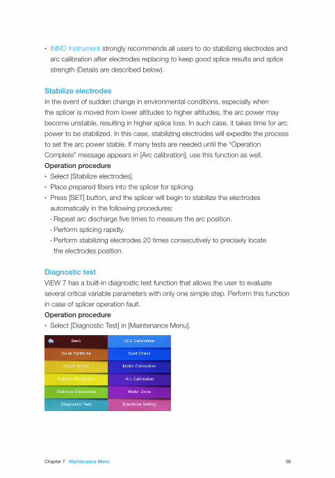
Diagnostic testVIEW 7 has a built-in diagnostic test function that allows the user to evaluate
several critical variable parameters with only one simple step. Perform this function
in case of splicer operation fault.
Operation procedure• Select [Diagnostic Test] in [Maintenance Menu].
Chapter 7 Maintenance Menu 37
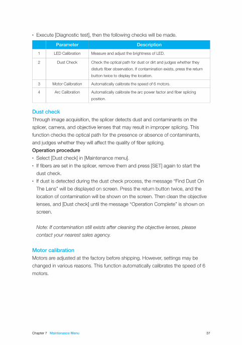
• Execute [Diagnostic test], then the following checks will be made.
Dust checkThrough image acquisition, the splicer detects dust and contaminants on the
splicer, camera, and objective lenses that may result in improper splicing. This
function checks the optical path for the presence or absence of contaminants,
and judges whether they will affect the quality of fiber splicing.
Operation procedure• Select [Dust check] in [Maintenance menu].• If fibers are set in the splicer, remove them and press [SET] again to start the
dust check.• If dust is detected during the dust check process, the message “Find Dust On
The Lens” will be displayed on screen. Press the return button twice, and the
location of contamination will be shown on the screen. Then clean the objective
lenses, and [Dust check] until the message “Operation Complete” is shown on
screen.
Note: If contamination still exists after cleaning the objective lenses, please
contact your nearest sales agency.
Motor calibrationMotors are adjusted at the factory before shipping. However, settings may be
changed in various reasons. This function automatically calibrates the speed of 6
motors.
Parameter Description
1 LED Calibration Measure and adjust the brightness of LED.
2 Dust Check Check the optical path for dust or dirt and judges whether they
disturb fiber observation. If contamination exists, press the return
button twice to display the location.
3 Motor Calibration Automatically calibrate the speed of 6 motors.
4 Arc Calibration Automatically calibrate the arc power factor and fiber splicing
position.
Chapter 7 Maintenance Menu 38
Operation procedure• Select [Motor Calibration] in [Maintenance Menu].• Load prepared fibers in the splicer, and press [SET].• Speeds for all motors are automatically calibrated. Upon completion,
the message “Operation Complete” will be displayed.
Note: Perform this function when “Fat” or “Thin” error occurs, or fiber aligning
or focusing takes too much time.
Arc calibrationAtmospheric conditions such as temperature, humidity and pressure are
constantly changing, which creates variability in the arc temperature. VIEW 7 is
equipped with temperature and pressure sensors that are used in a constant
feedback monitoring control system to maintain the arc power at a stable level.
However, changes in arc power due to electrode wear and glass adhesion cannot
be calibrated automatically. Also, the center position of arc discharge sometimes
shifts to the left or to the right. In this case, the fiber splicing position has to be
shifted in relation to the arc discharge center. It is necessary to perform an arc
power calibration to eliminate those problems.
Note: Performing arc calibration function changes the parameter of the system.
The arc power value will not be changed in the splice modes.
Operation procedure• Select [Arc Calibration] in [Maintenance Menu] to display arc calibration on the
screen.• Place prepared fibers into the splicer, and press [SET] to perform arc calibration.
Note: Use standard SM fiber for arc calibration. Use well-prepared fibers for arc
calibration since dust on the fiber surface affects arc calibration.
Chapter 7 Maintenance Menu 39
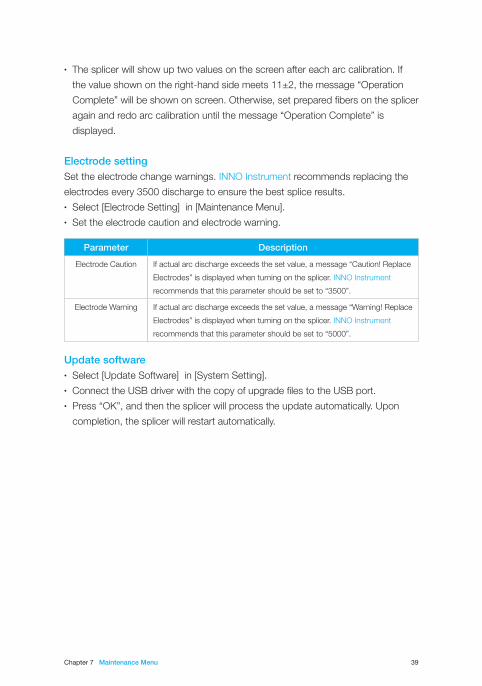
• The splicer will show up two values on the screen after each arc calibration. If
the value shown on the right-hand side meets 11±2, the message “Operation
Complete” will be shown on screen. Otherwise, set prepared fibers on the splicer
again and redo arc calibration until the message “Operation Complete” is
displayed.
Electrode settingSet the electrode change warnings. INNO Instrument recommends replacing the
electrodes every 3500 discharge to ensure the best splice results.• Select [Electrode Setting] in [Maintenance Menu].• Set the electrode caution and electrode warning.
Update software• Select [Update Software] in [System Setting].• Connect the USB driver with the copy of upgrade files to the USB port.• Press “OK”, and then the splicer will process the update automatically. Upon
completion, the splicer will restart automatically.
Parameter Description
Electrode Caution If actual arc discharge exceeds the set value, a message “Caution! Replace
Electrodes” is displayed when turning on the splicer. INNO Instrument
recommends that this parameter should be set to “3500”.
Electrode Warning If actual arc discharge exceeds the set value, a message “Warning! Replace
Electrodes” is displayed when turning on the splicer. INNO Instrument
recommends that this parameter should be set to “5000”.
40
Other Functions & Utilities
Data storageThis splicer stores up to 2000 splicing results. Contents of data stored are different
depending on the splicing mode.
Display splice record
Splicing results stored in the splicer can be displayed.• Select [Display Splice Record] in [Data Storage] menu.
Delete splice record
Splicing results can be cleared by part or whole.• Select [Delete Splice Record], and input specific number (Start Splice Record
and End Splicer Record) of splicing results to be cleared.• Select [Reset Splice Record], then the splicing results will be cleared.
Cancel data storage
If users do not want to save any splicing results, please select [ON] in [Cancel Data
Storage].
8
Chapter 8 Other Functions & Utilities 41
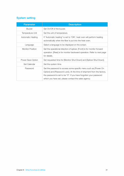
System setting
Parameter Description
Buzzer Set On/Off of the buzzer.
Temperature Unit Set the unit of temperature.
Automatic Heating If “Automatic heating” is set to “ON”, heat oven will perform heating
automatically when the fiber is put into the heat oven.
Language Select a language to be displayed on the screen.
Monitor Position Set the operational direction of splicer. [Front] is for monitor forward
operation. [Rear] is for monitor backward operation. Refer to next page
for details.
Power Save Option Set requested time for [Monitor Shut Down] and [Splicer Shut Down].
Set Calendar Set the system time.
Password Set the password to access some specific menu such as [Power On
Option] and [Password Lock]. At the time of shipment from the factory,
the password is set to be “0”. If you have forgotten your password
which you have set, please contact the sales agency.
Chapter 8 Other Functions & Utilities 42
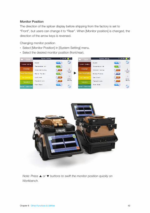
Monitor Position
The direction of the splicer display before shipping from the factory is set to
“Front”, but users can change it to “Rear”. When [Monitor position] is changed, the
direction of the arrow keys is reversed.
Changing monitor position• Select [Monitor Position] in [System Setting] menu.• Select the desired monitor position (front/rear).
Note: Press ▲ or ▼ buttons to swift the monitor position quickly on
Workbench.
Chapter 8 Other Functions & Utilities 43
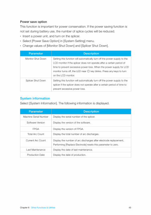
Power save option
This function is important for power conservation. If the power saving function is
not set during battery use, the number of splice cycles will be reduced.• Insert a power unit, and turn on the splicer.• Select [Power Save Option] in [System Setting] menu.• Change values of [Monitor Shut Down] and [Splicer Shut Down].
System informationSelect [System Information]. The following information is displayed.
Parameter Description
Monitor Shut Down Setting this function will automatically turn off the power supply to the
LCD monitor if the splicer does not operate after a certain period of
time to prevent excessive power loss. When the power supply for LCD
monitor turns off, the LED near ◎ key blinks. Press any keys to turn
on the LCD monitor.
Splicer Shut Down Setting this function will automatically turn off the power supply to the
splicer if the splicer does not operate after a certain period of time to
prevent excessive power loss.
Parameter Description
Machine Serial Number Display the serial number of the splicer.
Software Version Display the version of the software.
FPGA Display the version of FPGA.
Total Arc Count Display the total number of arc discharges.
Current Arc Count Display the number of arc discharges after electrode replacement.
Performing [Replace Electrode] resets this parameter to zero.
Last Maintenance Display the date of last maintenance.
Production Date Display the date of production.
44
Appendix I
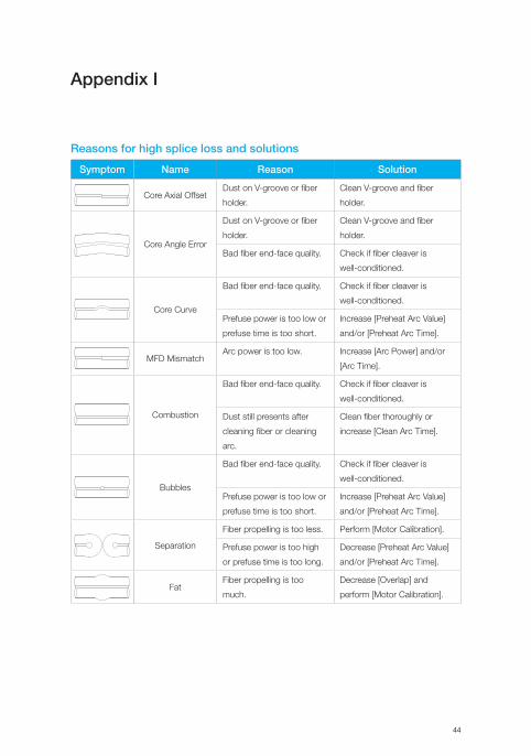
Reasons for high splice loss and solutions
Symptom Name Reason Solution
Core Axial OffsetDust on V-groove or fiber
holder.
Clean V-groove and fiber
holder.
Core Angle Error
Dust on V-groove or fiber
holder.
Clean V-groove and fiber
holder.
Bad fiber end-face quality. Check if fiber cleaver is
well-conditioned.
Core Curve
Bad fiber end-face quality. Check if fiber cleaver is
well-conditioned.
Prefuse power is too low or
prefuse time is too short.
Increase [Preheat Arc Value]
and/or [Preheat Arc Time].
MFD MismatchArc power is too low. Increase [Arc Power] and/or
[Arc Time].
Combustion
Bad fiber end-face quality. Check if fiber cleaver is
well-conditioned.
Dust still presents after
cleaning fiber or cleaning
arc.
Clean fiber thoroughly or
increase [Clean Arc Time].
Bubbles
Bad fiber end-face quality. Check if fiber cleaver is
well-conditioned.
Prefuse power is too low or
prefuse time is too short.
Increase [Preheat Arc Value]
and/or [Preheat Arc Time].
Separation
Fiber propelling is too less. Perform [Motor Calibration].
Prefuse power is too high
or prefuse time is too long.
Decrease [Preheat Arc Value]
and/or [Preheat Arc Time].
FatFiber propelling is too
much.
Decrease [Overlap] and
perform [Motor Calibration].

Appendix I 45
Note: A vertical line sometimes appears at the splice point when MM fibers or
dissimilar fibers (different diameters) are spliced. We call it as “Splicing line”. This
does not affect splice quality (such as splice loss and tensile strength).
Thin
Arc power is not adequate. Perform [Arc Calibration].
Some arc parameters are
not adequate.
Adjust [Preheat Arc Value],
[Preheat Arc Time],
or increase [Overlap].
LineSome arc parameters are
not adequate.
Adjust [Preheat Arc Value],
[Preheat Arc Time],
or [Overlap].
46
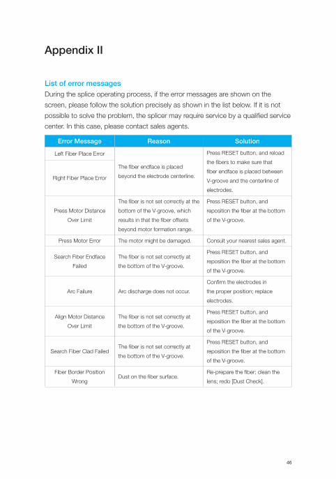
Appendix II
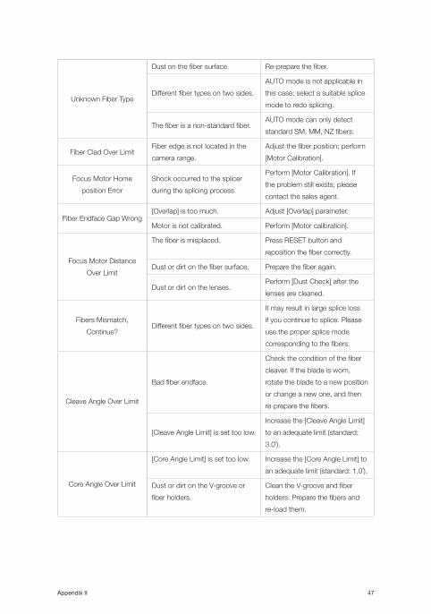
List of error messagesDuring the splice operating process, if the error messages are shown on the
screen, please follow the solution precisely as shown in the list below. If it is not
possible to solve the problem, the splicer may require service by a qualified service
center. In this case, please contact sales agents.
Error Message Reason Solution
Left Fiber Place Error
The fiber endface is placed
beyond the electrode centerline.
Press RESET button, and reload
the fibers to make sure that
fiber endface is placed between
V-groove and the centerline of
electrodes.
Right Fiber Place Error
Press Motor Distance
Over Limit
The fiber is not set correctly at the
bottom of the V-groove, which
results in that the fiber offsets
beyond motor formation range.
Press RESET button, and
reposition the fiber at the bottom
of the V-groove.
Press Motor Error The motor might be damaged. Consult your nearest sales agent.
Search Fiber Endface
Failed
The fiber is not set correctly at
the bottom of the V-groove.
Press RESET button, and
reposition the fiber at the bottom
of the V-groove.
Arc Failure Arc discharge does not occur.
Confirm the electrodes in
the proper position; replace
electrodes.
Align Motor Distance
Over Limit
The fiber is not set correctly at
the bottom of the V-groove.
Press RESET button, and
reposition the fiber at the bottom
of the V-groove.
Search Fiber Clad FailedThe fiber is not set correctly at
the bottom of the V-groove.
Press RESET button, and
reposition the fiber at the bottom
of the V-groove.
Fiber Border Position
WrongDust on the fiber surface.
Re-prepare the fiber; clean the
lens; redo [Dust Check].
Appendix II 47
Unknown Fiber Type
Dust on the fiber surface. Re-prepare the fiber.
Different fiber types on two sides.
AUTO mode is not applicable in
this case; select a suitable splice
mode to redo splicing.
The fiber is a non-standard fiber.AUTO mode can only detect
standard SM, MM, NZ fibers.
Fiber Clad Over LimitFiber edge is not located in the
camera range.
Adjust the fiber position; perform
[Motor Calibration].
Focus Motor Home
position Error
Shock occurred to the splicer
during the splicing process.
Perform [Motor Calibration]. If
the problem still exists, please
contact the sales agent.
Fiber Endface Gap Wrong[Overlap] is too much. Adjust [Overlap] parameter.
Motor is not calibrated. Perform [Motor calibration].
Focus Motor Distance
Over Limit
The fiber is misplaced. Press RESET button and
reposition the fiber correctly.
Dust or dirt on the fiber surface. Prepare the fiber again.
Dust or dirt on the lenses.Perform [Dust Check] after the
lenses are cleaned.
Fibers Mismatch,
Continue?Different fiber types on two sides.
It may result in large splice loss
if you continue to splice. Please
use the proper splice mode
corresponding to the fibers.
Cleave Angle Over Limit
Bad fiber endface.
Check the condition of the fiber
cleaver. If the blade is worn,
rotate the blade to a new position
or change a new one, and then
re-prepare the fibers.
[Cleave Angle Limit] is set too low.
Increase the [Cleave Angle Limit]
to an adequate limit (standard:
3.0˚).
Core Angle Over Limit
[Core Angle Limit] is set too low. Increase the [Core Angle Limit] to
an adequate limit (standard: 1.0˚).
Dust or dirt on the V-groove or
fiber holders.
Clean the V-groove and fiber
holders. Prepare the fibers and
re-load them.

Appendix II 48
Fiber Axis Align FailedToo large axial offset (>4.0㎛). Re-prepare the fibers.
The motor is not calibrated. Perform [Motor calibration].
Fiber is Dirty
Dust or dirt on the fiber surface. Prepare the fiber again.
The lenses are covered with dust.Perform [Dust check] after
cleaning the lenses.
[Clean Arc Time] is too short. Set [Clean Arc Time] to 180ms.
It is difficult to identify the fiber
core by using the method of core
alignment to splice.
Use MM splice mode (clad align-
ment) to splice the unidentified
fiber core.
Fat Splicing Point[Overlap] is too much. Adjust [Overlap] parameter.
The motor is not calibrated. Perform [Motor Calibration].
Thin Splicing Point
Arc power is too low. Perform [Arc Calibration].
The level of pre-discharge is
too high.
Decrease pre-discharge or pre-
discharge time.
Insufficient [Overlap]. Adjust [Overlap] parameter.
49
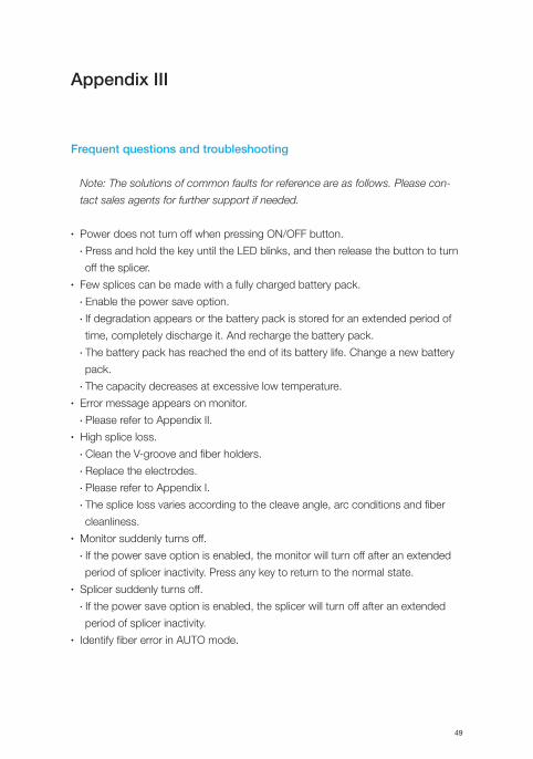
Appendix III
Frequent questions and troubleshooting
Note: The solutions of common faults for reference are as follows. Please con-
tact sales agents for further support if needed.
• Power does not turn off when pressing ON/OFF button. • Press and hold the key until the LED blinks, and then release the button to turn
off the splicer.• Few splices can be made with a fully charged battery pack.
• Enable the power save option.• If degradation appears or the battery pack is stored for an extended period of
time, completely discharge it. And recharge the battery pack.• The battery pack has reached the end of its battery life. Change a new battery
pack.• The capacity decreases at excessive low temperature.
• Error message appears on monitor.• Please refer to Appendix II.
• High splice loss.• Clean the V-groove and fiber holders.• Replace the electrodes.• Please refer to Appendix I.• The splice loss varies according to the cleave angle, arc conditions and fiber
cleanliness.• Monitor suddenly turns off.
• If the power save option is enabled, the monitor will turn off after an extended
period of splicer inactivity. Press any key to return to the normal state.• Splicer suddenly turns off.
• If the power save option is enabled, the splicer will turn off after an extended
period of splicer inactivity.• Identify fiber error in AUTO mode.
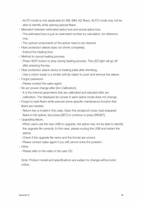
Appendix III 50
• AUTO mode is only applicable for SM, MM, NZ fibers. AUTO mode may not be
able to identify while splicing special fibers.• Mismatch between estimated splice loss and actual splice loss.
• The estimated loss is just an estimated number by calculation, for reference
only.• The optical components of the splicer need to be cleaned.
• Fiber protection sleeve does not shrink completely.• Extend the heating time.
• Method to cancel heating process.• Press HEAT button to stop during heating process. The LED light will go off
after pressing the key.• Fiber protection sleeve sticks to heating plate after shrinking.
• Use a cotton swab or a similar soft tip object to push and remove the sleeve.• Forgot password.
• Please contact the sales agent.• No arc power change after [Arc Calibration].
• It is the internal parameters that are calibrated and adjusted after arc
calibration. The displayed arc power in each splice mode does not change.• Forgot to load fibers while execute some specific maintenance function that
fibers are needed.• Return key is invalid in this case. Open the windproof cover, load prepared
fibers in the splicer, and press [SET] to continue or press [RESET].• Upgrading failure.
• When users use the new USB to upgrade, the splice may not be able to identify
the upgrade file correctly. In this case, please re-plug the USB and restart the
splicer.• Check if the upgrade file name and the format are correct.• Please contact sales agent if you still cannot solve the problem.
• Other• Please refer to the video in the user CD.
Note: Product model and specifications are subject to change without prior
notice.

www.innoinstrument.com
Europe Branch Office
Korea Head Office
China Branch Office
USA Branch Office
Over
70 countries
Exclusive distributors & dealers 97companies
Printed in Korea
Copyright ⓒ 2014 INNO Instrument Inc. All rights reserved.11, Sunhwan-ro 214beon-gil, Jungwon-gu, Seongnam-si, Gyeonggido 462-807, Republic of Korea tel 82-31-742-8755 fax 82-31-742-8799