Embed Size (px)
Citation preview

Remote quantum entanglement between two micromechanical oscillators∗
Ralf Riedinger,1, † Andreas Wallucks,2, † Igor Marinkovic,2, † Clemens
Loschnauer,1 Markus Aspelmeyer,1 Sungkun Hong,1, ‡ and Simon Groblacher2, §
1Vienna Center for Quantum Science and Technology (VCQ),Faculty of Physics, University of Vienna, A-1090 Vienna, Austria
2Kavli Institute of Nanoscience, Delft University of Technology, 2628CJ Delft, The Netherlands
Entanglement, an essential feature of quantum theory that allows for inseparable quantum cor-relations to be shared between distant parties, is a crucial resource for quantum networks [1]. Ofparticular importance is the ability to distribute entanglement between remote objects that can alsoserve as quantum memories. This has been previously realized using systems such as warm [2, 3]and cold atomic vapours [4, 5], individual atoms [6] and ions [7, 8], and defects in solid-state sys-tems [9–11]. Practical communication applications require a combination of several advantageousfeatures, such as a particular operating wavelength, high bandwidth and long memory lifetimes. Herewe introduce a purely micromachined solid-state platform in the form of chip-based optomechan-ical resonators made of nanostructured silicon beams. We create and demonstrate entanglementbetween two micromechanical oscillators across two chips that are separated by 20 centimetres.The entangled quantum state is distributed by an optical field at a designed wavelength near 1550nanometres. Therefore, our system can be directly incorporated in a realistic fibre-optic quantumnetwork operating in the conventional optical telecommunication band. Our results are an importantstep towards the development of large-area quantum networks based on silicon photonics.
In recent years, nanofabricated mechanical oscillatorshave emerged as a promising platform for quantum in-formation processing. The field of opto- and electrome-chanics has seen great progress, including ground-statecooling [12, 13], quantum interfaces to optical or mi-crowave modes [14, 15], mechanical squeezing [16–18] andsingle-phonon manipulation [19–22]. Demonstrations ofdistributed mechanical entanglement, however, have sofar been limited to intrinsic material resonances [23] andthe motion of trapped ions [8]. Entanglement of engi-neered (opto-)mechanical resonances, on the other hand,would provide a route towards scalable quantum net-works. The freedom of designing and choosing opticalresonances would allow operation in the entire frequencyrange of the technologically important C-, S- and L-bandsof fibre-optic telecommunications. Together with densewavelength-division multiplexing (on the ITU-T grid),this could enable quantum nodes separated by long dis-tances (about 100 km) that can communicate at largebandwidths. State-of-the-art engineered mechanical ele-ments have energy lifetimes that typically range betweenmicro- [15] and milliseconds [24], which would allow en-tanglement distribution on a regional level [25]. In ad-dition, these entangled mechanical systems could be in-terfaced with microwaves [26], opening up the possibilityof integrating superconducting quantum processors in thelocal nodes of the network.
Here we report on the observation of distributed en-tanglement between two nanomechanical resonators, me-
∗ This work was published in Nature 556, 473–477 (2018).† These authors contributed equally to this work.‡ [email protected]§ [email protected]
diated by telecommunication-wavelength photons. Weuse the DLCZ protocol [27], which was experimentallypioneered with ensembles of cold atoms [4]. The entan-glement is generated probabilistically through the condi-tional preparation of a single phonon, heralded by the de-tection of a signal photon that could originate from eitherof two identical optomechanical oscillators. Fabricationimperfections have previously limited the use of artificialstructures, requiring external tuning mechanisms to ren-der such systems indistinguishable. Here we demonstratenot only that obtaining sufficiently identical devices is infact possible through nanofabrication, but also that ourmethod could in principle be applied to more than twosystems.
The mechanical oscillators that we use in our experi-ment are nano-structured silicon beams with co-localizedmechanical and optical resonances. Radiation pressureforces and the photoelastic effect couple the optical andmechanical modes with a rate g0, causing the optical fre-quency to shift under the displacement of the mechan-ical oscillator [28]. This effect can be used to selec-tively address Stokes and anti-Stokes transitions by driv-ing the optical resonance with detuned laser beams, re-sulting in a linear optomechanical interaction. As wasrecently shown, this technique can be used to create non-classical mechanical and optomechanical states at thesingle-quantum level for individual devices by using pho-ton counting and post-selection [15, 21].
To apply the DLCZ scheme to the entanglement of twoseparate optomechanical crystals, a critical requirement isthat the photons emitted from the optomechanical cavi-ties must be indistinguishable. This can be achieved bycreating a pair of nanobeams with identical optical andmechanical resonances. Until now, however, fabrication
arX
iv:1
710.
1114
7v2
[qu
ant-
ph]
6 A
ug 2
018
2
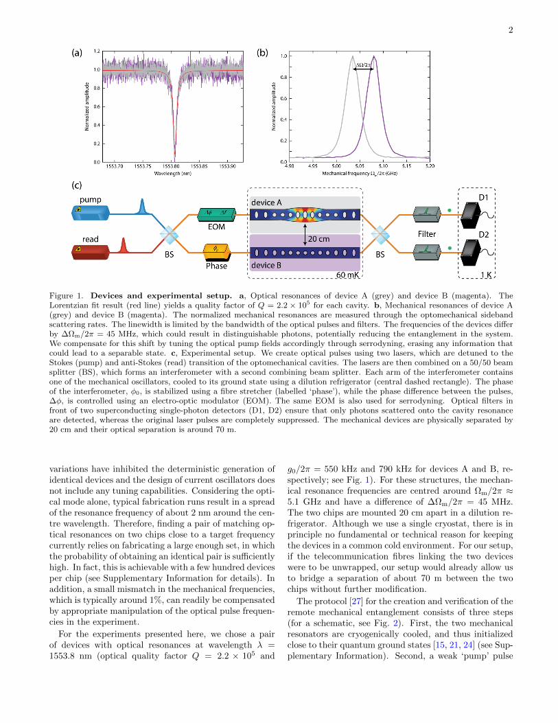
Figure 1. Devices and experimental setup. a, Optical resonances of device A (grey) and device B (magenta). TheLorentzian fit result (red line) yields a quality factor of Q = 2.2 × 10⁵ for each cavity. b, Mechanical resonances of device A(grey) and device B (magenta). The normalized mechanical resonances are measured through the optomechanical sidebandscattering rates. The linewidth is limited by the bandwidth of the optical pulses and filters. The frequencies of the devices differby ∆Ωm/2π = 45 MHz, which could result in distinguishable photons, potentially reducing the entanglement in the system.We compensate for this shift by tuning the optical pump fields accordingly through serrodyning, erasing any information thatcould lead to a separable state. c, Experimental setup. We create optical pulses using two lasers, which are detuned to theStokes (pump) and anti-Stokes (read) transition of the optomechanical cavities. The lasers are then combined on a 50/50 beamsplitter (BS), which forms an interferometer with a second combining beam splitter. Each arm of the interferometer containsone of the mechanical oscillators, cooled to its ground state using a dilution refrigerator (central dashed rectangle). The phaseof the interferometer, φ0, is stabilized using a fibre stretcher (labelled ‘phase’), while the phase difference between the pulses,∆φ, is controlled using an electro-optic modulator (EOM). The same EOM is also used for serrodyning. Optical filters infront of two superconducting single-photon detectors (D1, D2) ensure that only photons scattered onto the cavity resonanceare detected, whereas the original laser pulses are completely suppressed. The mechanical devices are physically separated by20 cm and their optical separation is around 70 m.
variations have inhibited the deterministic generation ofidentical devices and the design of current oscillators doesnot include any tuning capabilities. Considering the opti-cal mode alone, typical fabrication runs result in a spreadof the resonance frequency of about 2 nm around the cen-tre wavelength. Therefore, finding a pair of matching op-tical resonances on two chips close to a target frequencycurrently relies on fabricating a large enough set, in whichthe probability of obtaining an identical pair is sufficientlyhigh. In fact, this is achievable with a few hundred devicesper chip (see Supplementary Information for details). Inaddition, a small mismatch in the mechanical frequencies,which is typically around 1%, can readily be compensatedby appropriate manipulation of the optical pulse frequen-cies in the experiment.
For the experiments presented here, we chose a pairof devices with optical resonances at wavelength λ =1553.8 nm (optical quality factor Q = 2.2 × 10⁵ and
g0/2π = 550 kHz and 790 kHz for devices A and B, re-spectively; see Fig. 1). For these structures, the mechan-ical resonance frequencies are centred around Ωm/2π ≈5.1 GHz and have a difference of ∆Ωm/2π = 45 MHz.The two chips are mounted 20 cm apart in a dilution re-frigerator. Although we use a single cryostat, there is inprinciple no fundamental or technical reason for keepingthe devices in a common cold environment. For our setup,if the telecommunication fibres linking the two deviceswere to be unwrapped, our setup would already allow usto bridge a separation of about 70 m between the twochips without further modification.
The protocol [27] for the creation and verification of theremote mechanical entanglement consists of three steps(for a schematic, see Fig. 2). First, the two mechanicalresonators are cryogenically cooled, and thus initializedclose to their quantum ground states [15, 21, 24] (see Sup-plementary Information). Second, a weak ‘pump’ pulse

3
tuned to the upper mechanical sideband (at frequencyωpump = 2πc/λ + Ωm, where c is the speed of light), issent into a phase-stabilized interferometer (with a fixedphase difference φ0, see Fig. 1 and Supplementary Infor-mation) with one device in each arm. This drives theStokes process–that is, the scattering of a pump photoninto the cavity resonance while simultaneously creating aphonon [15]. The presence of a single phonon is heraldedby the detection of a scattered Stokes photon in one of oursuperconducting nanowire single-photon detectors. Thetwo optical paths of the interferometer are overlapped ona beam splitter, and a variable optical attenuator is seton one of the arms so that a scattered photon from ei-ther device is equally likely to reach either detector. Theheralding detection event therefore contains no informa-tion about which device the scattering took place in andthus where the phonon was created. The energy of thepulse is tuned to ensure that the scattering probabilityppump ≈ 0.7% is low, making the likelihood of simulta-neously creating phonons in both devices negligible. Theheralding measurement therefore projects the mechanicalstate into a superposition of a single-excitation state indevice A (|A〉 = |1〉A|0〉B) or device B (|B〉 = |0〉A|1〉B),with the other device remaining in the ground state. Thejoint state of the two mechanical systems
|Ψ〉=1√2
(|1〉A|0〉B ± eiθm(0)|0〉A|1〉B
)(1)
is therefore entangled, where θm(0) = φ0 is the phasewith which the mechanical state is initialized at delayτ = 0. This phase is determined from the relative phasedifference that the pump beam acquires in the two in-terferometer arms [4], which we can choose using our in-terferometer lock. However, because the two mechanicalfrequencies differ by ∆Ωm, the phase of the entangledstate will continue to evolve as θm(τ) = φ0 + ∆Ωmτ . Thesign in equation (1) reflects which detector is used forheralding, with + (−) corresponding to the positive (neg-ative) detector, as defined by the sign convention of theinterferometer phase φ0.
In the third step of our protocol, we experimentallyverify the entanglement between the two mechanical os-cillators. To achieve this, we map the mechanical stateonto an optical field using a ‘read’ pulse after a vari-able delay τ . This relatively strong pulse is tuned tothe lower mechanical sideband of the optical resonance(ωread = 2πc/λ − Ωm). At this detuning, the fielddrives the anti-Stokes transition–that is, a pump photonis scattered onto the cavity resonance while annihilatinga phonon [15]. Ideally, this state transfer will convert |Ψ〉into
|Φ〉=1√2
(|1〉rA|0〉rB ± e
i(θr+θm(τ))|0〉rA|1〉rB), (2)
where rA and rB are the optical modes in the two interfer-ometer arms. The state of the optical field now contains
pum
p
read
phononphoton photon
device A
device B
τ
p1
^
p2
^
r1
^
r2
^
mA
^
mB
^
rA
rB^
^
Figure 2. Creation and detection of entanglement be-tween two remote mechanical oscillators. A pump pulsedetuned to the Stokes sideband of two identical optomechani-cal resonators is sent into an interferometer, creating a singleexcitation in either device A or B. This process emits a pho-ton on resonance with one of the cavities, and the two possiblepaths are superimposed using a beam splitter (black square)when exiting the interferometer (left). Detection of this pho-ton in one of the single-photon detectors projects the two me-chanical systems into an entangled state, in which neither de-vice can be described separately. To verify this non-separablestate, an optical read pulse tuned to the anti-Stokes sidebandis sent into the interferometer with a delay of τ , de-exciting themechanical systems and emitting another on-resonance pho-ton into modes ri (i = A,B) with operators ri. The two opti-cal paths are again superimposed on the same beam splitter(right), and the photon is detected, allowing us to measurevarious second-order correlation functions, which are used totest an entanglement witness. The operators pj and rj, withj = 1, 2, denote the optical modes created from the pump andthe read pulses, respectively, after recombination on the beamsplitter and mi (i = A,B) are the operators of the mechanicalmodes. We note that in our experiment, the detectors usedfor the pump and read photons are identical (see Fig. 1).
the mechanical phase as well as the phase difference θr ac-quired by the read pulse. We can add an additional phaseoffset ∆φ to the read pulse in one of the interferometerarms so that θr = φ0 +∆φ by using an electro-optic phasemodulator, as shown in Fig. 1. Sweeping ∆φ allows us toprobe the relative phase θm(τ) between the superpositions|A〉 and |B〉 of the mechanical state for fixed delays τ . Toavoid substantial absorption heating creating thermal ex-citations in the oscillators, we limit the energy of the readpulse to a state-swap fidelity of about 3.4%, reducing thenumber of added incoherent phonons to about 0.07 at adelay of τ = 123 ns (see Supplementary Information).
So far we have neglected the consequence of slightlydiffering mechanical resonance frequencies for our herald-ing scheme. To compensate for the resulting frequencyoffset in the scattered (anti-) Stokes photons and to eraseany available ‘which device’ information, we shift thefrequency of the laser pulses by means of serrodyning(see Supplementary Information). Specifically, we use theelectro-optic phase modulator, which controls the phase
4
offset ∆φ, to also shift the frequency of the pump (read)pulses to device A by +∆Ωm (−∆Ωm). The frequencydifferences of the pulses in the two opposing paths can-cel out their mechanical frequency differences exactly, en-suring that the scattered photons at the output of theinterferometer are indistinguishable.
To confirm that the measured state is indeed entan-gled, we need to distinguish it from all possible sepa-rable states, that is, the set of all states for which sys-tems A and B can be described independently. A specif-ically tailored measure that can be used to verify thisnon-separability of the state is called an ‘entanglementwitness’. Here we use a witness that is designed for op-tomechanical systems [29]. In contrast to other path-entanglement witnesses based on partial state tomogra-phy, such as concurrence, this approach replaces measure-ments of third-order coherences, g(3), by expressing themas second-order coherences, g(2), assuming linear inter-actions between Gaussian states. This greatly simplifiesthe requirements and reduces the measurement times forour experiments. Because the coherences refer to the un-conditional states, the nonlinear detection and state pro-jection do not contradict these assumptions. The aboveassumptions are satisfied for our system because the ini-tial mechanical states of our devices are in fact thermalstates close to the corresponding quantum ground states(step 1 of our protocol; see Supplementary Information)and we use linearized optomechanical interactions (de-scribed in steps 2 and 3) [30]. The upper bound for thiswitness of mechanical entanglement is given by [29] (seeSupplementary Information).
Rm(θ, j) = 4 ·g
(2)r1,pj (θ) + g
(2)r2,pj (θ)− 1
(g(2)r1,pj (θ)− g(2)
r2,pj (θ))2, (3)
in a symmetric setup. In equation (3), θ = θr + θm,
j = 1, 2 denotes the heralding detectors and g(2)ri,pj =
〈r†i p†j ripj〉/〈r†i ri〉〈p†j pj〉 is the second-order coherence be-
tween the photons scattered by the pump pulse (with p†jand pj the creation and annihilation operators, respec-tively, of the mode going to detector j) and the converted
phonons from the read pulse (with r†j and rj the creationand annihilation operators, respectively, of the mode go-ing to detector j). For all separable states of the mechan-ical oscillators A and B, the witness yields Rm(θ, j) ≥ 1for any θ and j. Hence, if there exists a θ and j for whichRm(θ, j) < 1, the mechanical systems must be entangled.
Although entanglement witnesses are designed to be ef-ficient classifiers, they typically depend on the individualcharacteristics of the experimental setup. If, for exam-ple, the second beam splitter (see Fig. 1) were to mal-function and act as a perfect mirror–that is, if all pho-tons from device A (B) were transmitted to detector 1(2)–then Rm(θ, j) could still be less than 1 for separablestates. This is because the witness in equation (3) esti-mates the visibility of the interference between |A〉 and
Seco
nd o
rder
coh
eren
ce g
(2)
Phase ∆φ (π)-1.0 -0.5 0.0 0.5 1.0
0
1
2
3
4
5
6
7
8
9
10
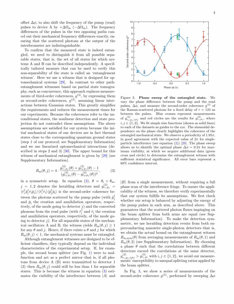
Figure 3. Phase sweep of the entangled state. Wevary the phase difference between the pump and the readpulses, ∆φ, and measure the second-order coherence g(2) ofthe Raman-scattered photons for a fixed delay of τ = 123 nsbetween the pulses. Blue crosses represent measurements
of g(2)ri,pj ,i 6=j and red circles are the results for g
(2)ri,pi , where
i, j ∈ 1, 2. We fit simple sine functions (shown as solid lines)to each of the datasets as guides to the eye. The sinusoidal de-pendence on the phase clearly highlights the coherence of theentangled mechanical state. We observe a periodicity of 1.95π,in good agreement with the expected value of 2π for single-particle interference (see equation (2)) [29]. The phase sweepallows us to identify the optimal phase ∆φ = 0.2π for max-imum visibility, at which we acquire additional data (greencross and circle) to determine the entanglement witness withsufficient statistical significance. All error bars represent a68% confidence interval.
|B〉 from a single measurement, without requiring a fullphase scan of the interference fringe. To ensure the appli-cability of the witness, we therefore verify experimentallythat our system fulfills its assumptions. We first checkwhether our setup is balanced by adjusting the energy ofthe pump pulses in each arm, as described above. Thisguarantees that the scattered photon fluxes impinging onthe beam splitter from both arms are equal (see Sup-plementary Information). To make the detection sym-metric, we use heralding detection events from both su-perconducting nanowire single-photon detectors–that is,we obtain the actual bound on the entanglement witnessRm,sym(θ) from averaging measurements of Rm(θ, 1) andRm(θ, 2) (see Supplementary Information). By choosinga phase θ such that the correlations between differentdetectors exceed the correlations at the same detector,
g(2)ri,pj ,i6=j > g
(2)ri,pi with i, j ∈ 1, 2, we avoid our measure-
ments’ susceptibility to unequal splitting ratios applied bythe beam splitter.
In Fig. 3, we show a series of measurements of thesecond-order coherence g(2), performed by sweeping ∆φ
5
with a readout delay of τ = 123 ns, which verify thecoherence between |A〉 and |B〉. Using these data, wechose an optimal phase setting θ = θopt with ∆φ = 0.2πfor the main experiment. We obtain Rm,sym(θopt) =0.74+0.12
−0.06, which is well below the separability bound of 1.By including measurements at the non-optimal adjacentphases ∆φ = 0 and 0.25π, the statistical uncertainty im-proves, and we obtain Rm,sym([θopt−0.2π, θopt+0.05π]) =0.74+0.08
−0.05. Hence, we experimentally observe entangle-ment between the two remote mechanical oscillators witha confidence level above 99.8%.
The coherence properties of the generated state can becharacterized through the decay of the visibility
V =max(g
(2)ri,pj )−min(g
(2)ri,pj )
max(g(2)ri,pj ) + min(g
(2)ri,pj )
. (4)
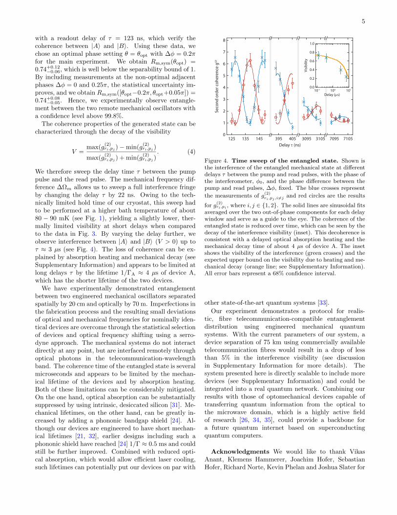
We therefore sweep the delay time τ between the pumppulse and the read pulse. The mechanical frequency dif-ference ∆Ωm allows us to sweep a full interference fringeby changing the delay τ by 22 ns. Owing to the tech-nically limited hold time of our cryostat, this sweep hadto be performed at a higher bath temperature of about80 − 90 mK (see Fig. 1), yielding a slightly lower, ther-mally limited visibility at short delays when comparedto the data in Fig. 3. By varying the delay further, weobserve interference between |A〉 and |B〉 (V > 0) up toτ ≈ 3 µs (see Fig. 4). The loss of coherence can be ex-plained by absorption heating and mechanical decay (seeSupplementary Information) and appears to be limited atlong delays τ by the lifetime 1/ΓA ≈ 4 µs of device A,which has the shorter lifetime of the two devices.
We have experimentally demonstrated entanglementbetween two engineered mechanical oscillators separatedspatially by 20 cm and optically by 70 m. Imperfections inthe fabrication process and the resulting small deviationsof optical and mechanical frequencies for nominally iden-tical devices are overcome through the statistical selectionof devices and optical frequency shifting using a serro-dyne approach. The mechanical systems do not interactdirectly at any point, but are interfaced remotely throughoptical photons in the telecommunication-wavelengthband. The coherence time of the entangled state is severalmicroseconds and appears to be limited by the mechan-ical lifetime of the devices and by absorption heating.Both of these limitations can be considerably mitigated.On the one hand, optical absorption can be substantiallysuppressed by using intrinsic, desiccated silicon [31]. Me-chanical lifetimes, on the other hand, can be greatly in-creased by adding a phononic bandgap shield [24]. Al-though our devices are engineered to have short mechan-ical lifetimes [21, 32], earlier designs including such aphononic shield have reached [24] 1/Γ ≈ 0.5 ms and couldstill be further improved. Combined with reduced opti-cal absorption, which would allow efficient laser cooling,such lifetimes can potentially put our devices on par with
395 405 3095 3105 7095 7105125 135 1450
1
2
3
4
5
6
7
8
Seco
nd o
rder
coh
eren
ce g
(2)
Delay τ (ns)
10-1 100 101
Delay (µs)
Visi
bilit
y
0.0
0.2
0.4
0.6
0.8
1.0
Figure 4. Time sweep of the entangled state. Shown isthe interference of the entangled mechanical state at differentdelays τ between the pump and read pulses, with the phase ofthe interferometer, φ0, and the phase difference between thepump and read pulses, ∆φ, fixed. The blue crosses represent
the measurements of g(2)ri,pj ,i 6=j and red circles are the results
for g(2)ri,pi , where i, j ∈ 1, 2. The solid lines are sinusoidal fits
averaged over the two out-of-phase components for each delaywindow and serve as a guide to the eye. The coherence of theentangled state is reduced over time, which can be seen by thedecay of the interference visibility (inset). This decoherence isconsistent with a delayed optical absorption heating and themechanical decay time of about 4 µs of device A. The insetshows the visibility of the interference (green crosses) and theexpected upper bound on the visibility due to heating and me-chanical decay (orange line; see Supplementary Information).All error bars represent a 68% confidence interval.
other state-of-the-art quantum systems [33].
Our experiment demonstrates a protocol for realis-tic, fibre telecommunication-compatible entanglementdistribution using engineered mechanical quantumsystems. With the current parameters of our system, adevice separation of 75 km using commercially availabletelecommunication fibres would result in a drop of lessthan 5% in the interference visibility (see discussionin Supplementary Information for more details). Thesystem presented here is directly scalable to include moredevices (see Supplementary Information) and could beintegrated into a real quantum network. Combining ourresults with those of optomechanical devices capable oftransferring quantum information from the optical tothe microwave domain, which is a highly active fieldof research [26, 34, 35], could provide a backbone fora future quantum internet based on superconductingquantum computers.
Acknowledgments We would like to thank VikasAnant, Klemens Hammerer, Joachim Hofer, SebastianHofer, Richard Norte, Kevin Phelan and Joshua Slater for

6
valuable discussions and help. We also acknowledge as-sistance from the Kavli Nanolab Delft, in particular fromMarc Zuiddam and Charles de Boer. This project wassupported by the European Commission under the MarieCurie Horizon 2020 initial training programme OMT(grant 722923), Foundation for Fundamental Researchon Matter (FOM) Projectruimte grants (15PR3210,16PR1054), the Vienna Science and Technology FundWWTF (ICT12-049), the European Research Council(ERC CoG QLev4G, ERC StG Strong-Q), the AustrianScience Fund (FWF) under projects F40 (SFB FOQUS)and P28172, and by the Netherlands Organisationfor Scientific Research (NWO/OCW), as part of theFrontiers of Nanoscience program, as well as through aVidi grant (680-47-541/994). R.R. is supported by theFWF under project W1210 (CoQuS) and is a recipient ofa DOC fellowship of the Austrian Academy of Sciencesat the University of Vienna.
[1] H. J. Kimble, Nature 453, 1023 (2008).[2] K. Jensen, W. Wasilewski, H. Krauter, T. Fernholz, B. M.
Nielsen, M. Owari, M. B. Plenio, A. Serafini, M. M. Wolf,and E. S. Polzik, Nature Phys. 7, 13 (2011).
[3] K. F. Reim, P. Michelberger, K. C. Lee, J. Nunn, N. K.Langford, and I. A. Walmsley, Phys. Rev. Lett. 107,053603 (2011).
[4] C. W. Chou, H. de Riedmatten, D. Felinto, S. V.Polyakov, S. J. van Enk, and H. J. Kimble, Nature 438,828 (2005).
[5] D. N. Matsukevich, T. Chanelieere, S. D. Jenkins, S.-Y.Lan, T. A. B. Kennedy, and A. Kuzmich, Phys. Rev.Lett. 96, 030405 (2006).
[6] S. Ritter, C. Nolleke, C. Hahn, A. Reiserer, A. Neuzner,M. Uphoff, M. Mucke, E. Figueroa, J. Bochmann, andG. Rempe, Nature 484, 195 (2012).
[7] D. L. Moehring, P. Maunz, S. Olmschenk, K. C. Younge,D. N. Matsukevich, L.-M. Duan, and C. Monroe, Nature449, 68 (2007).
[8] J. D. Jost, J. P. Home, J. M. Amini, D. Hanneke, R. Oz-eri, C. Langer, J. J. Bollinger, D. Leibfried, and D. J.Wineland, Nature 459, 683 (2009).
[9] I. Usmani, C. Clausen, F. Bussieres, N. Sangouard,M. Afzelius, and N. Gisin, Nature Photon. 6, 234 (2012).
[10] E. Saglamyurek, J. Jin, V. B. Verma, M. D. Shaw, F. Mar-sili, S. W. Nam, D. Oblak, and W. Tittel, Nature Photon.9, 83 (2015).
[11] B. Hensen, H. Bernien, A. E. Dreau, A. Reiserer, N. Kalb,M. S. Blok, J. Ruitenberg, R. F. L. Vermeulen, R. N.Schouten, C. Abellan, W. Amaya, V. Pruneri, M. W.Mitchell, M. Markham, D. J. Twitchen, D. Elkouss,S. Wehner, T. H. Taminiau, and R. Hanson, Nature 526,682 (2015).
[12] J. D. Teufel, T. Donner, D. Li, J. W. Harlow, M. S. All-man, K. Cicak, A. J. Sirois, J. D. Whittaker, K. W. Lehn-ert, and R. W. Simmonds, Nature 475, 359 (2011).
[13] J. Chan, T. P. M. Alegre, A. H. Safavi-Naeini, J. T.Hill, A. Krause, S. Groblacher, M. Aspelmeyer, and
O. Painter, Nature 478, 89 (2011).[14] T. Palomaki, J. Teufel, R. Simmonds, and K. Lehnert,
Science 342, 710 (2013).[15] R. Riedinger, S. Hong, R. A. Norte, J. A. Slater,
J. Shang, A. G. Krause, V. Anant, M. Aspelmeyer, andS. Groblacher, Nature 530, 313 (2016).
[16] E. E. Wollman, C. U. Lei, A. J. Weinstein, J. Suh, A. Kro-nwald, F. Marquardt, A. A. Clerk, and K. C. Schwab,Science 349, 952 (2015).
[17] J.-M. Pirkkalainen, E. Damskagg, M. Brandt, F. Massel,and M. A. Sillanpaa, Phys. Rev. Lett. 115, 243601 (2015).
[18] F. Lecocq, J. B. Clark, R. W. Simmonds, J. Aumentado,and J. D. Teufel, Phys. Rev. X 5, 041037 (2015).
[19] A. D. O’Connell, M. Hofheinz, M. Ansmann, R. C. Bial-czak, M. Lenander, E. Lucero, M. Neeley, D. Sank,H. Wang, M. Weides, J. Wenner, J. M. Martinis, andA. N. Cleland, Nature 464, 697 (2010).
[20] Y. Chu, P. Kharel, W. H. Renninger, L. D. Burkhart,L. Frunzio, P. T. Rakich, and R. J. Schoelkopf, Science358, 199 (2017).
[21] S. Hong, R. Riedinger, I. Marinkovic, A. Wallucks, S. G.Hofer, R. A. Norte, M. Aspelmeyer, and S. Groblacher,Science 358, 203 (2017).
[22] A. P. Reed, K. H. Mayer, J. D. Teufel, L. D. Burkhart,W. Pfaff, M. Reagor, L. Sletten, X. Ma, R. J. Schoelkopf,E. Knill, and K. W. Lehnert, Nature Phys. 13, 1163(2017).
[23] K. C. Lee, M. R. Sprague, B. J. Sussman, J. Nunn, N. K.Langford, X.-M. Jin, T. Champion, P. Michelberger, K. F.Reim, D. England, D. Jaksch, and I. Walmsley, Science334, 1253 (2011).
[24] S. M. Meenehan, J. D. Cohen, G. S. MacCabe, F. Marsili,M. D. Shaw, and O. Painter, Phys. Rev. X 5, 041002(2015).
[25] M. Razavi, M. Piani, and N. Lutkenhaus, Phys. Rev. A80, 032301 (2009).
[26] J. Bochmann, A. Vainsencher, D. D. Awschalom, andA. N. Cleland, Nature Phys. 9, 712 (2013).
[27] L. M. Duan, M. D. Lukin, J. I. Cirac, and P. Zoller,Nature 414, 413 (2001).
[28] J. Chan, Laser cooling of an optomechanical crystal res-onator to its quantum ground state of motion, Ph.D. the-sis, California Institute of Technology (2012).
[29] K. Børkje, A. Nunnenkamp, and S. M. Girvin, Phys. Rev.Lett. 107, 123601 (2011).
[30] W. Wieczorek, S. G. Hofer, J. Hoelscher-Obermaier,R. Riedinger, K. Hammerer, and M. Aspelmeyer, Phys.Rev. Lett. 114, 223601 (2015).
[31] T. Asano, Y. Ochi, Y. Takahashi, K. Kishimoto, andS. Noda, Opt. Express 25, 1769 (2017).
[32] R. N. Patel, C. J. Sarabalis, W. Jiang, J. T. Hill, andA. H. Safavi-Naeini, Phys. Rev. Applied 8, 041001 (2017).
[33] N. Maring, P. Farrera, K. Kutluer, M. Mazzera,G. Heinze, and H. de Riedmatten, Nature 551, 485(2017).
[34] A. Rueda, F. Sedlmeir, M. C. Collodo, U. Vogl, B. Stiller,G. Schunk, D. V. Strekalov, C. Marquardt, J. M. Fink,O. Painter, G. Leuchs, and H. G. L. Schwefel, Optica 3,597 (2016).
[35] A. P. Higginbotham, P. S. Burns, M. D. Urmey, R. W.Peterson, N. S. Kampel, B. M. Brubaker, G. Smith, K. W.Lehnert, and C. A. Regal, arXiv:1712.06535 (2017).
[36] K. Fang, J. Luo, A. Metelmann, M. H. Matheny, F. Mar-quardt, A. A. Clerk, and O. Painter, Nature Phys. 13,

7
465 (2017).[37] R. C. Cumming, Proc. IRE 45, 175 (1957).[38] K. K. Wong, R. M. D. L. Rue, and S. Wright, Opt. Lett.
7, 546 (1982).[39] R. Horodecki, P. Horodecki, M. Horodecki, and
K. Horodecki, Rev. Mod. Phys. 81, 865 (2009).[40] S. Hill and W. K. Wootters, Phys. Rev. Lett. 78, 5022
(1997).[41] S. G. Hofer, W. Wieczorek, M. Aspelmeyer, and K. Ham-
merer, Phys. Rev. A 84, 52327 (2011).[42] A. Kuzmich, W. P. Bowen, A. D. Boozer, A. Boca, C. W.
Chou, L.-M. Duan, and H. J. Kimble, Nature 423, 731(2003).
[43] K. C. Lee, Generation of room-temperature entanglementin diamond with broadband pulses, Ph.D. thesis, Univer-sity of Oxford (2012).

8
SUPPLEMENTARY INFORMATION
Device fabrication and characterization
The devices in the main part are fabricated as describedin reference [21]. The most crucial steps for generatingtwo identical chips are the electron beam lithography andthe inductively coupled plasma reactive ion etching. Webeamwrite and etch on a single proto-chip containing twosets of devices. This chip is then diced into two halves,each with several hundred nominally identical resonators.The structures are subsequently released in 40% hydroflu-oric acid and cleaned with the RCA method, followed bya dip in 2% hydrofluoric acid. When characterizing thetwo chips, we find the center wavelengths to be 1552.4 nmon chip A and 1550.0 nm on chip B (see Figure S1). Thestandard deviation on the spread of the optical resonancesis around 2 nm on both chips. For the experiments in themain text, we search for resonances that overlap to within10% of their linewidth, which is equal to around 100 MHz.We find a total of 5 pairs fulfilling this requirement within234 devices tested per chip.
In order to verify that finding identical devices is notjust lucky coincidence and that this can even be donewith a smaller sample size per chip, one can estimate thenumber of devices needed for a birthday paradox typeapproach. Therefore, we assume a pair of chips with 234devices each that are centered at the same target wave-length. Taking similar parameters as found in our actualchips, we use a spread in resonance wavelength of 2 nmand we define resonances to be identical if they matchto within 100 MHz. While the probability of obtaininga single device exactly at the center wavelength is only0.03%, the probability of finding two matching devices atany wavelength within this distribution is 99.9996%. Thisis reduced if an offset in the mean wavelength of the twochips is introduced. For an offset of 2.5 nm, the probabil-ity is 99.98%, and for 5 nm, it is still 92.7%. By extend-ing this approach to, for example, four chips, with thesame parameters as above, no offset in the center wave-length and 500 devices per chip, we calculate the prob-ability of finding four identical resonances to be 51.6%.Such a quartet would directly enable experiments on en-tanglement swapping and tests of a Bell inequality, asproposed by DLCZ. Further improvements could includepost-fabrication wavelength tuning, as has recently beendemonstrated for similar devices [36]. This could signifi-cantly improve the prospect of scalability of our approach,as it would allow to fabricate identical devices more de-terministically.
In addition, the mechanical resonances are also suscep-tible to fabrication errors and vary by up to 50 MHz forour devices. To overcome this mismatch, we use serro-dyne frequency shifting (see sections below).
Wavelength (nm)1545 1547 1549 1551 1553 1555 1557
# of
dev
ices
0
5
10
15
20
25
30
35
40
45
1559
Figure S1. Distribution of optical wavelengths. We plota histogram (bin size 1 nm) of the optical resonance wave-lengths for a large set of devices on each of the chips contain-ing devices A (gray) and B (magenta). The fits of a Gaussiandistribution to the data sets (red solid lines) give a standarddeviation of 2.3 nm and 2.0 nm, respectively. The large overlapof the optical resonance frequencies highlights the feasibilityof extending the entanglement to even more optomechanicaldevices in the future.
Experimental setup
A detailed drawing of the experimental setup is shownin Figure S2. The light sources for our pump andread beams are two New Focus 6728 CW lasers, tunedand stabilized on their respective sideband of the opti-cal resonance. The beams are filtered by MicronOpticsFFP-TF2 tunable optical filters in order to reduce thelaser phase noise in the GHz regime. We then proceedto generate the actual pump and read pulses by driv-ing acousto-optic modulators (Gooch&Housego T-M110-0.2C2J-3-F2S) with an arbitrary function generator (Tek-tronic AFG3152C). These pulses are then combined on avariable ratio coupler (Newport F-CPL-1550-N-FA). Thecombined optical mode is subsequently split by anothervariable ratio coupler and fed into the Mach Zehnder in-terferometer. The coupling ratio is adjusted to primarilycompensate for a small difference in total losses betweentwo paths. The power in the interferometer arms can ad-ditionally be balanced by an electrically driven variableoptical attenuator (Sercalo VP1). We reflect the pulsesfrom the two devices via optical circulators and recom-bine on a 50/50 coupler (measured deviation of 0.6%, seebelow). The strong pump pulses are filtered with twoMicronOptics FFP-TF2 fiber filters per detection arm,tuned to transmit only the scattered (anti-) Stokes pho-tons (bandwidth 50 MHz). We detect the resonant pho-tons with superconducting nanowire single photon detec-tors (Photonspot) and register their arrival times on a

9
TimeHarp 260 NANO correlation board.
Serrodyne frequency shifting
In our experiment, the mechanical frequency of de-vice B (Ωm,B) is greater than of device A (Ωm,A) by∆Ωm = 2π · 45 MHz. If we were to send pump pulseswith exactly the same frequency ωpump to both of thedevices, they would produce scattered photons with fre-quencies ωo,A = ωpump−Ωm,A and ωo,B = ωpump−Ωm,B =ωo,A −∆Ωm. This frequency mismatch of scattered pho-tons from the two devices would make them distinguish-able, therefore preventing the entangled state. A simplesolution is to shift the frequency of the pump pulse goingto the device A by ∆Ωm, i.e. ωpump,A = ωpump − ∆Ωm.We experimentally realize this by electrically driving theelectro-optic phase modulator on the path to device A,with a sawtooth waveform. This so-called serrodynemodulation with frequency ωs = ∆Ωm and peak-to-peakphase amplitude of 2π results in an optical frequency shiftof ωs [37, 38]. We use an arbitrary waveform generator(Agilent 81180A, bandwidth DC to 600 MHz) to generatethe sawtooth voltage signal, amplify it with a broadbandamplifier (Minicircuits TVA-R5-13A+, bandwidth 0.5 to1000 MHz) and apply it to the optical phase modula-tor (Photline MPZ-LN-10-P-P-FA-FA-P, bandwidth DCto 12 GHz). We also apply an additional DC-bias to theserrodyne signal in order to generate a fixed phase offset∆φ in the interferometer arms. Due to the high analogbandwidth of the AWG compared to the frequency shiftof 45 MHz, higher order sidebands were negligible andwere not observed in the experiment.
Phase stabilization of the interferometer
For stabilizing the phase of the interferometer, we usean additional laser pulse ∼5 µs after the read pulse.To produce these auxiliary pulses, we also use the red-detuned laser that generates the read pulses and sendthem along the same beam paths. After being reflectedfrom the optical filters in the detection line, the pulsesare re-routed by optical circulators and picked up by abalanced detector (see Figure S2). These signals are thensent to a PID controller, which regulates a fiber stretcherto stabilize the relative path length and therefore lockingthe phase of the interferometer on a slow timescale (i.e.with the experiment repetition period of 50 µs).
In principle, the read or pump pulses that are reflectedoff the filter cavities could also be used for the phase lock-ing. However, the serrodyne modulation during pumpand read results in a beat signal of the pulses behind thebeam splitter. This beating requires more sophisticatedsignal processing, which we avoid by using the auxiliarypulses, during which the serrodyne modulation is off. We
note that the auxiliary pulses also induce some absorp-tion heating of the devices. However, the 50 µs repetitionperiod is sufficiently long compared to the decay timesof the devices for the extra heating not to influence ourexperimental result.
Entanglement witness and Systematic Errors
The entanglement witness [39]
R(τ, j) =
⟨m†A(τ)mA(τ)m†B(τ)mB(τ)
⟩j∣∣∣∣⟨m†A(τ)mB(τ)
⟩j
∣∣∣∣2(S1)
derived in reference [29] is based on the concurrence [40]of the bipartite mechanical system. Here, the conditionalaverage 〈o〉j = 〈o p†j pj〉/〈p
†j pj〉 for an operator o is its ex-
pectation value of the state heralded by a Stokes photondetected by detector j. The mi (m†i ) are the mechani-cal annihilation (creation) operators of device i = A,B.While R is experimentally not directly accessible, the up-per bound to this witness Rm, see Eq. (3), is a measurablequantity in our interferometry setup. The derivation ofthe inequality Rm ≥ R, as described in reference [29]and its supplementary material, is based on several of as-sumptions: The unheralded state must be Gaussian at alltimes, and the interference on the combining beamsplit-ter must be symmetric. In this section, we would like todiscuss the validity of each of these assumptions in moredetail.
To obtain Rm, threefold coincidence measurements arere-expressed as twofold coincidences, which can be donefor Gaussian states. Note that as the degrees of sec-ond order coherence in Eq. (3) are measured between thepump and the read pulse, they are applied to this Gaus-sian state, not to the heralded, non-Gaussian entangledstate |Ψ〉 ∼ |A〉 + eiθ|B〉. We ensure that the mechani-cal states at the beginning of our protocol are Gaussianby allowing sufficiently long thermalization times (7x themechanical decay time) prior to any optical manipula-tions. Consequently, the initial state is thermal, whichfor a bosonic system [15, 21] implies Gaussian quadraturestatistics [30]. Next, all optomechanical interactions in-volved in our protocol are linear [41], therefore conservingthe Gaussianity of the state [30]. Specifically, the Stokesprocess is described by the linear interaction Hamilto-nian HS ∝ g0m
†i o†i + h.c. and the anti-Stokes process by
HAS ∝ g0mio†i + h.c. for device i = A,B with the annihi-
lation (creation) operator of optical resonance oi (o†i ).Unintentional interactions, like absorption heating,
happen probabilistically and in a remote frequencyregime, such that it effectively acts as a Gaussian ther-mal bath [21, 24]. Though not strictly contributing to themechanical state, we also consider false positive detection

10
read
pump
AWG
φ0
Device A
Device B
PID
AWG
EOM
AOMFilter
Filter SNSPD
VRC BSVRC
VOA
Figure S2. Experimental setup. A detailed schematics of our setup is shown here and described in the text. AOM arethe acousto-optic modulators, AWG the arbitrary waveform generators, VRC the variable ratio couplers, EOM the electro-optic modulator, VOA the variable optical attenuator, BS the 50/50 beamsplitter and SNSPD the superconducting nanowiresingle-photon detectors.
events: drive photons leaking through the filter stages canbe described by a coherent state (with Gaussian intensityfluctuations). Detection of stray photons and electricallycaused false positive events are rare (∼0.3% of the to-tal count rate in the detection window) and uncorrelated(autocorrelation g(2)(0) = 1.05 ± 0.09), such that it isreasonable to model them as a Gaussian process as well.More specifically, we observe an average added noise of∼0.14 phonons during the measurement, from which theindividual contributions of leaked drive photons, back-ground detection events, and optical absorption heatingcan be estimated with additional measurements (for de-tails see the section on ”Second Order Coherence andEntanglement”). With the latter being a thermal processand therefore yielding Gaussian quadrature statistics, andan estimation of the initial thermal occupation from thenominal cryostat temperature, this leaves ∼ 4+2.8
−2.7 · 10−2
phonons in device A and ∼ 0+1.4−0 · 10−2 in device B of
unidentified origin. These are likely thermal phononsstemming from the non-ideal thermalization of the chipswith their environment [15, 21].
For the modes leaving the interferometer rj, pj, refer-ence [29] assumes an ideal 50/50 beamsplitter with equalpowers on each input. Small experimental deviationsfrom this idealized scenario result in quadratic correc-tions to the witness. For example, when the ratio of readphotons at the beamsplitter originating from devices Aand B is 1 + δ, the measurable upper bound changes toRm(1+δ2/2) ≥ R for small δ. In our experimental setup,we choose a fused fiber beamsplitter with a measured de-viation of 0.6%, leading to a relative correction on theorder of 10−5. Experimentally, we cannot achieve powerbalancing at the input of the beamsplitter for photonsscattered from the pump and the read pulses at the sametime because the devices have slightly different thermal
occupation. We choose to match the detection rates ofheralding photons, i.e. photons scattered by the pumppulse. This preserves the unknown origin of the herald-ing photons. Differences in the optomechanical couplingstrength and optical losses on the path from the deviceto the combining beamsplitter are compensated by ad-justing the drive power in each path. After the balancingprocedure, the relative difference in count rates of herald-ing photons is below 2%, limited by the measurementprecision during the balancing run and laser power fluc-tuations during the measurements. This leads to a rel-ative correction of the witness below 10−3. The slightlydifferent heating dynamics between devices A and B re-sult in a measured flux ratio deviation of the scatteredreadout photons of δ ∼ 5 − 10%. It can easily be seenfrom Equation (3) that an increased heating will increasethe witness Rm, and therefore the heating induced im-balance does not limit the validity of the witness. Yet,neglecting the thermal origin of the imbalancing, employ-ing the correction Rm(1+δ2/2) ≥ R, we obtain a relativesystematic correction of 0.5% to our result in the worstcase scenario. Adding all systematic errors, we obtain aconservative upper bound of all relative systematic cor-rections of ∼0.5%. Consequently, we use a reduced clas-sicality bound of Rm ≥ 0.995 instead of 1, reducing theconfidence level slightly from 99.84% to 99.82%.
Statistical Analysis
Results in the text and figures are given as maximumlikelihood values and, where applicable, with a confi-dence interval of ±34% around this value. For the sec-ond order coherences g
(2)ri,pj , (i, j = 1, 2), we apply bi-
nomial statistics based on the number of counted two-

11
fold coincidences, which dominates the statistical uncer-tainty [15]. The entanglement witness Rm (θ, j) in Eq. (3)
is a non-trivial function of multiple such g(2)ri,pj , expressed
here as Rm (θ, j) ≡ Rm
(g
(2)r1,pj (θ) , g
(2)r2,pj (θ)
). To es-
timate its confidence intervals, we discretize the prob-ability density function of the second order coherences
P (g(2)ri,pj ∈ [a; a+ δa]) at equidistant a = nδa, n ∈ N. The
probabilities for finding Rm in an interval [f, f + δf ] is
then given by P (Rm ∈ [f, f + δf ]) =∑
(a,b)∈M P (g(2)r1,pj ∈
[a, a + δa])P (g(2)r2,pj ∈ [b, b + δb]) on the set M for which
Rm(a, b) ∈ [f, f + δf ]∀(a, b) ∈ M. For the optimalread phase θopt we obtain as maximum likelihood val-ues for the witness bounds Rm(θopt, 1) = 0.612+0.152
−0.057
and Rm(θopt, 2) = 0.846+0.210−0.090. We obtain the sym-
metrized witness by treating the experimentally observedRm(θopt, 1) and Rm(θopt, 2) as two independent measure-
ments of the expectation value Rm, sym(θ) ≡ 〈Rm(θ, 1)〉 !=
〈Rm(θ, 2)〉 of the optomechanical state in a symmetricsetup with no detector noise. For a realistic setup with de-tectors exhibiting different noise properties, without lossof generality, let detector j have more false positive de-tection events than detector i. We then find the sym-metrized witness 〈Rm(θopt, i)〉 ≤ Rm, sym ≤ 〈Rm(θopt, j)〉to be an upper bound to the entanglement witness of thestate heralded by the better detector i. Consequently1 > Rm, sym ≥ Rm(θopt, i) ≥ R implies entanglementbetween the two remote mechanical oscillators. The ob-served values yield a confidence level for Rm, sym < 1 of98.4%. When correcting for the conservative upper boundof systematic errors, see above, the confidence level forhaving observed entanglement remains at 98.3%.
The complete counting statistics of the witness mea-surement at θopt are accumulated over N = 1.114 · 109
trials (i.e. sets of pulses). We obtain C(p1) = 111134and C(p2) = 184114 counts for photons scattered by thepump pulse on detectors i = 1, 2 and C(r1) = 108723and C(r2) = 167427 counts from the read pulse. Thisyields the coincidence counts Cri,pj , (i, j = 1, 2) forcounts on detector i, heralded by detector j, Cr1,p1 = 9,Cr2,p1 = 130, Cr1,p2 = 129, Cr2,p2 = 37.
For non-optimal phases θ 6= θopt, Rm(θ, i) ≥Rm(θopt, i). Consequently, by adding the photon countsof measurements from an interval [θ1, θ2], the resultingRm([θ1, θ2], i) ≥ Rm(θ ∈ [θ1, θ2], i) serves as an upperbound to any phase θ within that interval. Including themeasurements at the non-optimal phase ∆φ = 0, we ob-tain Rm([θopt−0.2π, θopt], 1) = 0.66+0.114
−0.055 and Rm([θopt−0.2π, θopt], 2) = 0.806+0.129
−0.071, resulting in Rm, sym([θopt −0.2π, θopt]) = 0.74+0.08
−0.05 ≥ Rm, sym(θopt). The confidencelevel for Rm, sym < 1 is 99.84%, dropping to 99.82% whencorrecting for the conservative upper bound for system-atic errors. Note that for states heralded only with themore efficient detector 1, we already have a confidencelevel for entanglement between the two mechanical os-
cillators of 99.50%, including corrections for systematicerrors.
The statistics of the witness within the extended phaseregion are obtained from N = 1.949·109 experimental tri-als. We get C(p1) = 196080 and C(p2) = 322608 countsfor photons scattered by the pump pulse on detectorsi = 1, 2 and C(r1) = 194023 and C(r2) = 300373 countsfrom the read pulse. This yields the coincidence countsCri,pj , (i, j = 1, 2) for counts on detector i, heraldedby detector j, Cr1,p1 = 16, Cr2,p1 = 223, Cr1,p2 = 242,Cr2,p2 = 67.
Second Order Coherence and Entanglement
The second order coherence between the scattered pho-tons from the pump pulse and signal phonons trans-
fered by the read pulse after a delay t, g(2)i,rp(t) =
〈r†j p†j rjpj〉/〈r†j rj〉〈p†j pj〉, of the individual devices i = A,B,
allows to us quantify the total noise contribution lim-iting the interference visibility. The measurements areperformed the same way as described in the main text,however with the optical path to the other device blocked(see Fig. 2). Though there is no fundamental differencebetween the detectors j = 1, 2, we only use detector j = 2for the single device measurements. Following [42] andstarting from a thermal state for the mechanical systemρm and vacuum |0〉〈0|o in the optical sidebands we obtainin the low temperature limit
g(2)i,rp(t) ≈ 1 +
e−Γit
ni,th(t) + ppump,i · e−Γit + nleak + nbg,
(S2)where ni,th 1 is the mean phonon occupation of the
device, ppump,i nth is the Stokes excitation probabil-ity, nleak nth is the average number of leaked pumpphotons per transfered phonon, and nbg nth is the av-erage number of background counts per detected phonon.
At a delay of τ = 123 ns 1/Γi we measure g(2)A,rp =
7.1+1.2−0.9 and g
(2)B,rp = 9.6+1.1
−0.9. With calibrated rates of
nbg = 3·10−3, ppump,A = 0.56·10−2, ppump,B = 0.80·10−2
and leaks at detector 1 nleak,1 = 4.2 · 10−2 and detector2 nleak,2 = 3.2 · 10−2 we can estimate the number of in-coherent phonons to be nth,A = 11.9+2.8
−2.7 · 10−2 for device
A and nth,B = 6.9+1.4−1.3 · 10−2 for device B. In a more de-
tailed analysis, including the mechanical decay measure-ment (see below), we can estimate that absorption by thepump pulse contributes npump ∼ 3 ·10−2 phonons and ab-sorption from the read pulse contributes nread ∼ 5 · 10−2
phonons. This suggest, that the performance of device Ais limited by imperfect thermalization with the cryostatat a temperature of 60 mK.
The interference contrast of the entangled state, i.e.
Ce(t) = max(g(2)ri,pj(t, θ)) − min(g
(2)ri,pj(t, θ)) is bound by

12
device Adevice B
Calib
rate
d co
unt r
ate
(pho
nons
)
0.0
0.2
0.4
0.6
0.8
Delay t (µs)0 5 10 15 20 25
Figure S3. Pump-probe experiment. The experiment reveals the response of the devices mechanical modes to the initialoptical pump. See text for details. Error bars are s.d.
the cross correlation of the individual devices Ce,max(t) ≈min(g
(2)A,rp(t), g
(2)B,rp(t)) − 1 [43]. A pump-probe measure-
ment of the thermal response of the devices [15] allowsus to predict the cross correlations and thus an upperbound to the interference contrast. We excite the deviceswith a blue detuned pump pulse with ppump,A = 2.8%(ppump,B = 4.0%) and vary the delay of a read (or probe)pulse with 5.6% (8.0%) state swap fidelity for device A(B). Note that for this experiment, we deliberately choosepulse energies higher than for the interference experi-ments in order to reduce the measurement time. Asis done for sideband asymmetry [15, 21], the scatteringrate of the probe pulse can be converted into the numberof phonons at time t, when using the rate of the pumppulse (after scaling the signal according to the pump-to-probe power ratio) as a reference signal of single-phononstrength. This is only valid when nth 1 at the timeof pump pulse, which we find is the case later in the sec-tion. The results of these measurements are shown in Fig-ure S3. We observe an initial rise in phonon occupationafter the pump pulse, followed by a decay to an equi-librium state. The delayed heating can be understoodby the presence of long lived high frequency phonons,which weakly couple to the 5 GHz modes under inves-tigation. We model these high frequency phonons by aneffective thermal bath, exponentially decaying with rateγi. This results in the rate equation ni(t) = −Γini(t) +kie−γit+Γini,init of the mean occupation number ni of de-
vice i = A,B. The additional bath couples with strengthki, and the thermal environment of the chip has an equi-librium temperature of ni,init. The detected signal ofthe probe pulse di(t) = ni,pump(t) + ni,final contains theaverage phonon number ni,pump(t) = ni(t) − ni,init in-
duced by the pump beam, as well as a constant offsetni,final = ni,init + ni,probe + nleak + nbg given by the ther-mal environment ni,init, the false positive events nleak
and nbg and the heating during the probe pulse itselfni,probe. Consequently, we fit the pump-probe data withthe general solution of the above differential equationdi(t) = ai ·e−Γit−bi ·e−γit+ni,final, with ai, bi fitting pa-rameters and including the offset ni,final of the probe pulsedetection rate. We obtain 1/ΓA = 4.0 µs, 1/ΓB = 5.8 µs,1/γA = 0.5 µs and 1/γB = 0.5 µs. Using the cali-brated false positive detection rates and estimating theequilibrium occupation from the thermal environmentni,init ∼ 1/(e~Ω/kBT−1), with the Boltzmann constant kBand cryostat temperature T , we can obtain the individ-ual contributions to the absorption heating by the pump(ni,pump) and the probe pulse (ni,probe) for any given de-lay t. Adapting the number of phonons added by the opti-cal drive pulses ni,pump and ni,probe for the lower energies,under the assumption of linear absorption and optome-chanical processes, we obtain an estimate of the thermaloccupation ni,th(t) = ni(t) + ni,probe − ppump,ie
−Γit dur-ing the entanglement experiment. Using the calibratedrates and equation (S2), we can obtain an upper boundto the interference contrast Ce,max (see above) and there-fore also for the visibility Vmax = Ce,max/(Ce,max + 2),which is shown in Figure 4.
Rates and Extrapolation of Results
In order to highlight the scalability of the mechanicalentanglement, we recapitulate the detection rates in theentanglement witness measurement. The experiment is

13
repeated every 50 µs, limited by the thermalization timeof the mechanical modes. Using the counting statistics ofthe measurement at the optimal phase θopt, see above, wehave a probability of pherald ≈ 2.7 · 10−4 and the uncon-ditional probability to also detect the anti-Stokes photonfrom the readout pulse of pread ≈ 2.8 ·10−7. These proba-bilities contain the optomechanically generated photons,leaked pump photons and background counts. In thecurrent setup these rates are limited by losses in the fil-tering setup and low optomechanical scattering rates toretain the effects of absorption heating. When the twomechanical devices are placed in two separate refriger-ators and placed in different locations, additional fiberwould be inserted, causing additional losses. While thedetection rate of leaked pump photons reduces in thesame manner as the of the optomechanical photons, therate of background counts stays the same. Consequently,the signal-to-noise ratio reduces, lowering the normalizedcross-correlation between Stokes and anti-Stokes pho-tons. In the present measurements, the inverse signal-to-background ratio is nbg,1 = 2.9 · 10−3 (nbg,2 = 3.2 · 10−3)for detectors 1 (2). The most reliable estimate of the sec-ond order coherence of device A, which has worse prop-erties, can be extracted from the observed interference
contrast, resulting in g(2)A,rp ∼ 7.5 ± 0.35, as it has better
statistics than the direct measurement. For device B, we
use the direct measurement g(2)B,rp = 9.6+1.1
−0.9. To maintainan interference contrast of 95% of the current level, thesecond order coherence of both devices is allowed to de-crease to ∼7.1. With equation (S2) we can estimate thatan additional loss of 5.4 dB (10.6 dB) loss in the opti-cal path from device A (B) to the combining beamsplit-ter decreases the signal-to-background ratio, such that
g(2)A,rp ≈ g
(2)B,rp ≈ 7.1. Using the nominal attenuation of
commercial low-loss telecom fiber (Corning SMF-28 ULL∼0.17 dB/km), we can estimate that an additional fiberlength of 94+8
−12 km could be inserted between the devices.The projected entanglement witness in this configurationis Rm ∼ 0.76 and would need roughly the same numberof coincidence events to clear the classicality bound of 1by 3 standard deviations. Including the reduced scatter-ing rates from matching both paths, this would require∼170 days of integration time, including a 15% overheadtime for stabilization of filters and interferometer as wellas data management. Reducing the separation distanceto 75 km, i.e. an additional fiber length of 32 km (43 km)between device A (B) and the beamsplitter, requires 38days of continuous measurement time for a statisticallysignificant demonstration of remote entanglement. Whileour cryostat currently only allows for a few weeks of mea-surements at a time due to technical limitations, muchlonger times should in principle be easily achievable.