Embed Size (px)
Citation preview
UNCLASSIFIED
UNCLASSIFIED
VIDEO TELECONFERENCE SECURITY TECHNICAL
IMPLEMENTATION GUIDE (STIG) OVERVIEW
Version 1, Release 2
07 February 2014
Developed by DISA for the DoD
UNCLASSIFIED VTC STIG Overview, V1R2 DISA Field Security Operations
07 February 2014 Developed by DISA for the DoD
ii
UNCLASSIFIED
Trademark Information
Names, products, and services referenced within this document may be the trade names,
trademarks, or service marks of their respective owners. References to commercial vendors and
their products or services are provided strictly as a convenience to our users, and do not
constitute or imply endorsement by DISA FSO of any non-Federal entity, event, product,
service, or enterprise.
UNCLASSIFIED VTC STIG Overview, V1R2 DISA Field Security Operations
07 February 2014 Developed by DISA for the DoD
iii
UNCLASSIFIED
TABLE OF CONTENTS
Page
1. INTRODUCTION..................................................................................................................1
1.1 Background ..........................................................................................................................1 1.2 Authority ..............................................................................................................................1 1.3 Scope ....................................................................................................................................1 1.4 Vulnerability Severity Category Code Definitions ..............................................................1 1.5 STIG Distribution .................................................................................................................4
1.6 Document Revisions ............................................................................................................4
2. INTRODUCTION TO VTC TECHNOLOGY ...................................................................5
2.1 Definitions ............................................................................................................................6 2.2 VTC Endpoints .....................................................................................................................7 2.3 Point-to-Point Communications or Conferences ...............................................................11 2.4 Multipoint Conferences ......................................................................................................11
2.5 Ad hoc Conferences ...........................................................................................................14 2.6 VTC as a C2 Communications Media ...............................................................................14
2.7 Classified/Un-Classified or Secure/Non-Secure Conferencing Systems ...........................16 2.7.1 Periods Processing .............................................................................................................17
3. VTU/VTC ENDPOINT SECURITY ..................................................................................19
3.1 DoD Access Control and Auditing Policy Compliance .....................................................20 3.2 Confidentiality ....................................................................................................................20
3.2.1 Confidentiality of Information in the Physical Environment ............................................21 3.2.2 Confidentiality while the VTU is Inactive/in Standby ......................................................21
3.2.2.1 Power-Off the VTU When Inactive .................................................................................. 22 3.2.2.2 Disable the VTU When Powered & Inactive .................................................................... 22 3.2.2.3 Sleep Mode ....................................................................................................................... 22
3.2.2.4 Incoming Call Notification ............................................................................................... 23 3.2.2.5 Auto-Answer Availability ................................................................................................. 23
3.2.2.6 Auto-Answer Use Mitigations .......................................................................................... 23 3.2.3 Confidentiality While the VTU is Active ..........................................................................24 3.2.3.1 Audio Pickup and Broadcast SOP .................................................................................... 24 3.2.3.2 Information In View Of the Camera SOP......................................................................... 24
3.2.3.3 Incoming Calls While In a Conference ............................................................................. 25
3.2.3.4 Disable VTU Remote Monitoring .................................................................................... 25
3.2.3.5 VTU Remote Monitoring Password ................................................................................. 26 3.2.3.6 Remote Monitoring Notification....................................................................................... 26 3.2.3.7 Remote Monitoring Operator Clearance ........................................................................... 26 3.2.3.8 Far End Camera Control ................................................................................................... 26 3.2.4 Conference Media and Signaling Confidentiality ..............................................................26
3.2.4.1 Encryption of Signaling and Signaling Security ............................................................... 27 3.2.4.2 Encryption of Media ......................................................................................................... 28 3.2.4.3 FIPS 140-2 Validated Encryption ..................................................................................... 28
3.2.4.4 Encryption Indicator ......................................................................................................... 28
UNCLASSIFIED VTC STIG Overview, V1R2 DISA Field Security Operations
07 February 2014 Developed by DISA for the DoD
iv
UNCLASSIFIED
3.2.4.5 User Validation Of Encryption ......................................................................................... 29
3.3 VTC Endpoint Access Control ...........................................................................................29 3.3.1 Change Default Passwords ................................................................................................29
3.3.2 Password Display during Logon ........................................................................................30 3.3.3 Password/PIN Strength or Complexity ..............................................................................30 3.3.4 Passwords for Different VTU Functions ...........................................................................32 3.3.5 VTC Endpoint User Access Control ..................................................................................33 3.3.6 Manual Password Management SOP .................................................................................34
3.3.7 One Time Use “Local Meeting Password” ........................................................................34 3.3.8 Configuration/Administration Session Timeout ................................................................34 3.4 Media Streaming from a VTU/CODEC over IP ................................................................35 3.4.1 Use of Streaming in General ..............................................................................................37 3.4.2 Streaming Indicator ............................................................................................................37
3.4.3 SOP for CODEC Streaming...............................................................................................37 3.4.4 User Training for CODEC Streaming................................................................................37
3.4.5 Blocking Configuration for VTU/CODEC Streaming ......................................................37 3.4.6 VTU/CODEC Streaming Configuration ............................................................................38
3.5 PC Data and Presentation Sharing .....................................................................................38 3.5.1 PC Data and Presentation Sharing SOP .............................................................................38
3.5.2 PC Data and Presentation Sharing User Training ..............................................................39 3.5.3 PC Data and Presentation Sharing Software ......................................................................39 3.6 VTC Endpoint CODEC API Issues ...................................................................................40
3.6.1 Password for API Configuration Administrative Command Access .................................40 3.6.2 API Command Encryption and Authentication .................................................................41
3.7 Remote Management/Configuration IP Protocol Concerns ...............................................41
3.7.1 Use Secure Management Protocols ...................................................................................41
3.7.2 Disable Unnecessary Protocols ..........................................................................................41 3.7.3 SNMP Requirements .........................................................................................................42
3.7.4 Management/Configuration IP addresses ..........................................................................42 3.8 VTC Endpoint Firmware/Software Version RE: Password Compromise .........................42 3.8.1 Use Latest Firmware, Software, and Patches .....................................................................42 3.9 DoD Logon “Notice (Warning) and Consent Banner” ......................................................43 3.10 VTC Infrastructure and Management Appliances/Applications ........................................45
3.10.1 Compliance with all applicable STIGs ..............................................................................45 3.11 VTC Recording, Archiving, and Streaming Devices .........................................................45 3.12 PC Workstations as VTC Endpoints: Requirements ..........................................................46
4. POLICIES, DOCUMENTATION, APPROVALS, SOPS, USER AGREEMENTS,
AND TRAINING .........................................................................................................................47
4.1 VTC Endpoint Office Installation Policy ...........................................................................47 4.2 DAA Approval for VTC Implementation ..........................................................................47
4.3 Local VTC endpoint Implementation, Operation, and Use Policy – SOPs .......................48 4.4 VTC Endpoint User/Administrator Training .....................................................................48 4.5 VTC Endpoint User’s Agreement and Training Acknowledgment ...................................49 4.6 VTC Endpoint User’s Guide ..............................................................................................49
5. LOCAL NETWORK SECURITY FOR VTC ..................................................................50
UNCLASSIFIED VTC STIG Overview, V1R2 DISA Field Security Operations
07 February 2014 Developed by DISA for the DoD
v
UNCLASSIFIED
5.1 LAN Service Segregation ..................................................................................................50
5.1.1 Wireless LAN Access ........................................................................................................52 5.1.1.1 Wireless STIG Compliance .............................................................................................. 52 5.1.1.2 Simultaneous Wired and Wireless LAN Connection ....................................................... 52
5.1.1.3 Disable Wireless Support .................................................................................................. 52 5.1.1.4 Wireless Conference Room Implementation .................................................................... 53 5.1.2 Endpoint Authentication to the LAN/Port Security ...........................................................53
6. IP BASED VTC ENCLAVE BOUNDARY CROSSING ISSUES ..................................54
6.1 Network Address Translation (NAT) .................................................................................54
6.2 VTC Capable Firewall .......................................................................................................55 6.3 H.323 Firewall Traversal Technologies .............................................................................56 6.4 IP Based Ports and Protocols Used In VTC .......................................................................58
6.5 DoD Ports and Protocols Management ..............................................................................61 6.5.1 VTC ports and protocols in the PPS CAL .........................................................................61 6.5.2 PPS registration ..................................................................................................................63
7. SECURE/NON-SECURE VTC SECURITY .....................................................................64
7.1 Classified / Un-Classified Conferencing Systems .............................................................64
8. VTC HUB/MCU SECURITY .............................................................................................68
8.1 Access Control for Multipoint Conferences ......................................................................68 8.2 Conference Scheduling Systems ........................................................................................69
8.2.1 Scheduling system access control ......................................................................................69
APPENDIX A. ACRONYMS ....................................................................................................70
UNCLASSIFIED VTC STIG Overview, V1R2 DISA Field Security Operations
07 February 2014 Developed by DISA for the DoD
vi
UNCLASSIFIED
LIST OF TABLES
Page
Table 1-1. Vulnerability Severity Category Code Definitions ...................................................... 2 Table 6-1. IP Port Numbers Used in Firewall Traversal .............................................................. 57 Table 6-2. IP Port Numbers Used in Video Teleconferencing ..................................................... 61 Table 6-3. H.323 VTC PPS status in the PPS CAL ...................................................................... 63
UNCLASSIFIED VTC STIG Overview, V1R2 DISA Field Security Operations
07 February 2014 Developed by DISA for the DoD
vii
UNCLASSIFIED
LIST OF FIGURES
Page
Figure 2-2. VTC Endpoint Components and Connections ............................................................. 9 Figure 2-3. Point-to-Point VTC Connectivity .............................................................................. 11 Figure 2-4. Multipoint VTC Connectivity .................................................................................... 13 Figure 7-1. Secure / Non-Secure VTU Components and Connections ........................................ 66
UNCLASSIFIED VTC STIG Overview, V1R2 DISA Field Security Operations
07 February 2014 Developed by DISA for the DoD
viii
UNCLASSIFIED
This page intentionally left blank.
UNCLASSIFIED VTC STIG Overview, V1R2 DISA Field Security Operations
07 February 2014 Developed by DISA for the DoD
1
UNCLASSIFIED
1. INTRODUCTION
1.1 Background
Video teleconferencing (VTC) systems are comprised of multiple products and services working
together to provide point-to-point and point-to-multipoint video conferencing. This overview
gives technology-specific background and information specific to the architecture of VTC
servers. Included also are security review considerations to prepare for periodic assessments.
The associated Security Technical Implementation Guide (STIG), provides security policy and
configuration requirements for VTC implementations. Special considerations for classified or
periods processing VTC services are included in this revision.
1.2 Authority
DoD Directive (DoDD) 8500.1 requires that “all IA and IA-enabled IT products incorporated
into DoD information systems shall be configured in accordance with DoD-approved security
configuration guidelines” and tasks Defense Information Systems Agency (DISA) to “develop
and provide security configuration guidance for IA and IA-enabled IT products in coordination
with Director, NSA.” This document is provided under the authority of DoDD 8500.1.
Although SRGs and STIGs implement an applicable subset of IA controls for specific types of
systems, all applicable IA controls must be applied to information systems. The current DoD IA
controls are specified in DoDI 8500.2. Draft DoDI 8500.02aa states that “All DoD ISs and
platform IT systems, including non-National Security System (NSS), shall be categorized in
accordance with CNSSI 1253, and implement a corresponding set of security controls that are
published in NIST SP 800-53.” SRGs and derived STIGs are based on NIST SP 800-53.
1.3 Scope
This document is a requirement for all DoD administered systems and all systems connected to
DoD networks. These requirements are designed to assist Security Managers (SMs), Information
Assurance Managers (IAMs), Information Assurance Officers (IAOs), and System
Administrators (SAs) with configuring and maintaining security controls. This guidance
supports DoD system design, development, implementation, certification, and accreditation
efforts.
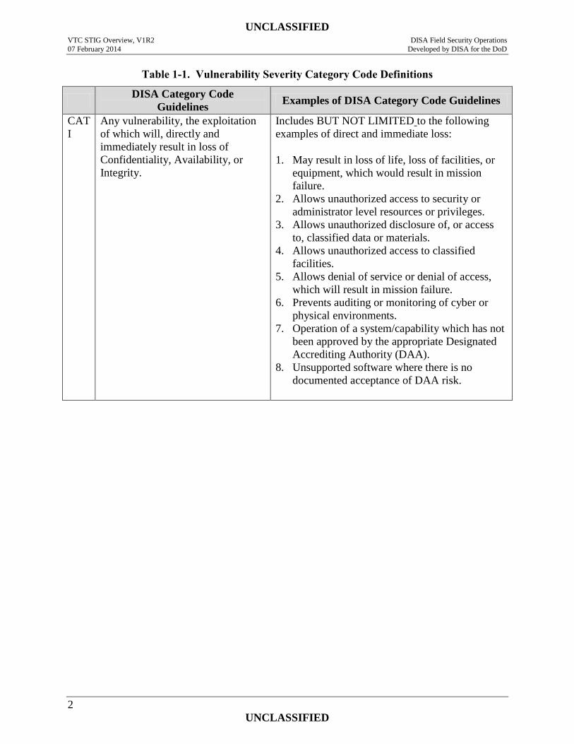
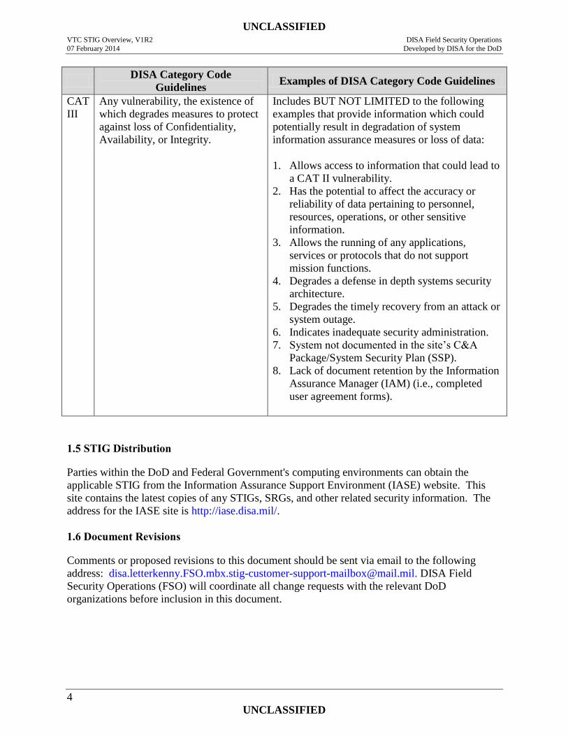
1.4 Vulnerability Severity Category Code Definitions
Severity Category Codes (referred to as CAT) are a measure of vulnerabilities used to assess a
facility or system security posture. Each security policy specified in this document is assigned a
Severity Code of CAT I, II, or III.
UNCLASSIFIED VTC STIG Overview, V1R2 DISA Field Security Operations
07 February 2014 Developed by DISA for the DoD
2
UNCLASSIFIED
Table 1-1. Vulnerability Severity Category Code Definitions
DISA Category Code
Guidelines Examples of DISA Category Code Guidelines
CAT
I
Any vulnerability, the exploitation
of which will, directly and
immediately result in loss of
Confidentiality, Availability, or
Integrity.
Includes BUT NOT LIMITED to the following
examples of direct and immediate loss:
1. May result in loss of life, loss of facilities, or
equipment, which would result in mission
failure.
2. Allows unauthorized access to security or
administrator level resources or privileges.
3. Allows unauthorized disclosure of, or access
to, classified data or materials.
4. Allows unauthorized access to classified
facilities.
5. Allows denial of service or denial of access,
which will result in mission failure.
6. Prevents auditing or monitoring of cyber or
physical environments.
7. Operation of a system/capability which has not
been approved by the appropriate Designated
Accrediting Authority (DAA).
8. Unsupported software where there is no
documented acceptance of DAA risk.
UNCLASSIFIED VTC STIG Overview, V1R2 DISA Field Security Operations
07 February 2014 Developed by DISA for the DoD
3
UNCLASSIFIED
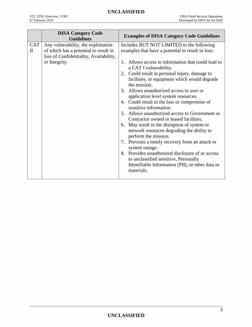
DISA Category Code
Guidelines Examples of DISA Category Code Guidelines
CAT
II
Any vulnerability, the exploitation
of which has a potential to result in
loss of Confidentiality, Availability,
or Integrity.
Includes BUT NOT LIMITED to the following
examples that have a potential to result in loss:
1. Allows access to information that could lead to
a CAT I vulnerability.
2. Could result in personal injury, damage to
facilities, or equipment which would degrade
the mission.
3. Allows unauthorized access to user or
application level system resources.
4. Could result in the loss or compromise of
sensitive information.
5. Allows unauthorized access to Government or
Contractor owned or leased facilities.
6. May result in the disruption of system or
network resources degrading the ability to
perform the mission.
7. Prevents a timely recovery from an attack or
system outage.
8. Provides unauthorized disclosure of or access
to unclassified sensitive, Personally
Identifiable Information (PII), or other data or
materials.
UNCLASSIFIED VTC STIG Overview, V1R2 DISA Field Security Operations
07 February 2014 Developed by DISA for the DoD
4
UNCLASSIFIED
DISA Category Code
Guidelines Examples of DISA Category Code Guidelines
CAT
III
Any vulnerability, the existence of
which degrades measures to protect
against loss of Confidentiality,
Availability, or Integrity.
Includes BUT NOT LIMITED to the following
examples that provide information which could
potentially result in degradation of system
information assurance measures or loss of data:
1. Allows access to information that could lead to
a CAT II vulnerability.
2. Has the potential to affect the accuracy or
reliability of data pertaining to personnel,
resources, operations, or other sensitive
information.
3. Allows the running of any applications,
services or protocols that do not support
mission functions.
4. Degrades a defense in depth systems security
architecture.
5. Degrades the timely recovery from an attack or
system outage.
6. Indicates inadequate security administration.
7. System not documented in the site’s C&A
Package/System Security Plan (SSP).
8. Lack of document retention by the Information
Assurance Manager (IAM) (i.e., completed
user agreement forms).
1.5 STIG Distribution
Parties within the DoD and Federal Government's computing environments can obtain the
applicable STIG from the Information Assurance Support Environment (IASE) website. This
site contains the latest copies of any STIGs, SRGs, and other related security information. The
address for the IASE site is http://iase.disa.mil/.
1.6 Document Revisions
Comments or proposed revisions to this document should be sent via email to the following
address: [email protected]. DISA Field
Security Operations (FSO) will coordinate all change requests with the relevant DoD
organizations before inclusion in this document.
UNCLASSIFIED VTC STIG Overview, V1R2 DISA Field Security Operations
07 February 2014 Developed by DISA for the DoD
5
UNCLASSIFIED
2. INTRODUCTION TO VTC TECHNOLOGY
VTC is an extension of traditional telephony technologies (i.e., dial up telephone service) with
the added feature of being able to see the person or persons with whom one is talking. Another
way to consider VTC technology is as an extension or combination of television, which provides
the audio and video communication aspect, and telephony or telecommunications which provides
the addressable, bi-directional connectivity. The results of which are a bidirectional, “closed
circuit”, dial-able, TV system. The television portion of the technology uses video display
screens (televisions/video monitors/projectors), video cameras, microphones, and speakers at
each location connected to a Coder-Decoder (CODEC). The CODEC is the interface between
the analog voice/video devices in the system and the addressable connectivity or transmission
portion of the system. The CODEC converts the analog signals to a digital format that is
compatible with the transmission media (and vice versa). The CODEC also has the capability to
interface and convert presentation and whiteboard information. The combined digital signal is
then transmitted to the remote location via a telecommunications network which is either TDM
or IP based. Quality VTC communications requires much higher bandwidth than voice or
traditional data communications. The actual bandwidth required is dependent upon the CODEC
and compression algorithm used. The typical minimum bandwidth required is 128Kbps with
384Kbps being typical and required for quality video using ISDN. Similarly, bandwidths on an
IP network typically range from 384Kbps to 768Kbps. Some CODECs require as much as
2Mbps in support of high definition video. Due to the overhead required in an Ethernet network,
these bandwidths will actually require 460.8Kbps, 921.6Kbps, and 2.458Mbps respectively, to
achieve proper throughput on the LAN.
Classically, the telecommunications network used for VTC connectivity has been (and still is
today) a traditional circuit switched network such as the Defense Switched Network (DSN)
and/or PSTN. The DSN is the preferred network for DoD VTC connectivity. Both of these
networks are based in TDM technologies and typically provide Integrated Services Digital
Network (ISDN) lines for access to the network. Both Basic Rate Interface (BRI) and Primary
Rate Interface (PRI) ISDN lines are used. Addressability is handled as with any other telephone
instrument, the address is the phone number associated with the line from the circuit switch to
the instrument.
Within the circuit switched network, the bandwidth requirements of VTC systems necessitate the
use of one or more ISDN lines from the circuit switch to the VTC location. The ISDN line(s) is
(are) interfaced with the CODEC using a modem like device called an Inverse Multiplexer
(IMUX). The IMUX also provides the dialing capability required by the network. Some
CODECs can interface with an external IMUX to control this dialing capability, while other
CODECs contain an internal or integrated IMUX. The protocol used for VTC transmission
across the circuit switched network is H.320. The external IMUX is required for
secure/classified dial-up sessions across an unclassified ISDN network. This arrangement is
discussed later in this document.
VTC systems/CODECs can also be interconnected via an IP based network. In fact the industry
is migrating heavily toward using today’s ubiquitous IP based connectivity. This eliminates the
IMUX function and/or device, as well as the expensive ISDN lines. The protocol that was
UNCLASSIFIED VTC STIG Overview, V1R2 DISA Field Security Operations
07 February 2014 Developed by DISA for the DoD
6
UNCLASSIFIED
developed for VTC transmission across an IP based network is H.323. This is in reality a suite
of protocols that provides the complete range of VTC capabilities. Some VTC systems are
migrating to the Session Initiation Protocol (SIP) (as are VoIP systems), however, SIP does not
provide all of the VTC control and feature functionality that H.323 does today. These
capabilities are under development. H.323 and SIP are signaling protocols used for the setup and
control of the VTC session. The session content or media is carried across the network using
Real Time Protocol (RTP) or Secure RTP (SRTP).
Many of today’s CODECs include both IP and ISDN capabilities. The ISDN capability is
provided via serial interfaces for use with an external IMUX or via an onboard IMUX.
2.1 Definitions
Before going on with the discussion of VTC technology, its vulnerabilities, and IA requirements,
the terms used in this document need to be defined to identify various people and their roles
associated with the VTC system and its operation. These are as follows:
User: a user of VTC equipment is one who operates the equipment and/or displays
presentations or whiteboard information using the equipment. Users have basic operating
privileges. A user is the operator of a conference room based system or the operator of
an office based or personal VTC device.
Conferee or Attendee: a person attending a VTC in person that is not a “user”.
Participant: a “user” that is participating in a connected or active VTC session using
their VTC equipment. While, in the English language, a participant can be considered a
conferee, and vice versa, a distinction is made for the purpose this document to maintain
clarity.
Facilitator: the “user” facilitating the VTC. This person is typically the user that has
the knowledge to set up a VTC session but does not participate in it, while other users
only operate the devices that display presentations and whiteboard information.
Chair: a “user” who operates the controls of the VTC system and/or the audio visual
equipment in a conference room or the person leading a VTC.
Administrator: a person responsible for the proper configuration and management of
the VTC system, equipment, or device. An administrator may also serve as, or be
referred to as, a “user”, “facilitator”, or “chair”.
UNCLASSIFIED VTC STIG Overview, V1R2 DISA Field Security Operations
07 February 2014 Developed by DISA for the DoD
7
UNCLASSIFIED
2.2 VTC Endpoints
A VTC endpoint is the human interface to the overall VTC system. It is the “thing” (device or
application) at the end of the wire where the electronic conference and human interaction occurs.
VTC endpoints take various forms as will be described in this section.
VTC endpoints can be referred to by additional names. These are Video Teleconferencing Unit
(VTU), and VTC/Video End Instrument (EI). The term EI comes from the combination of the
term endpoint and telephony parlance where a telephone is typically called a subscriber
instrument. An EI can refer to a telephone, VTU, or VTC endpoint.
The first VTC endpoint was a “videophone” system developed by AT&T and introduced to the
public at the world’s fair in 1964. It was dubbed “Picturephone”, and subsequently offered it as
a service in 1970. This was a personal communications device that flopped due to its initial cost
and the cost of the lines to operate it.
Early cost effective business VTC endpoints were developed and based upon the conference
room model. This model is still widely used today and supports conferences having multiple
people at each of the locations in the conference. The video cameras, microphones, speakers,
and video display screens are built into the conference room to provide maximum coverage of all
people in the room. There may also be an electronic whiteboard or document camera used for
the transmission of hand drawn sketches and other physical documents to all conference
participants. These types of VTC systems are typically referred to as VTC Suites. VTC suites
typically include a complete audio visual control system with controls for room lighting,
camera/microphone selection, camera positioning, etc. Some systems also implement the
capability for a facilitator or chair person to control the camera(s) of the remote location. This is
called Far End Camera Control (FECC).
Many of VTC endpoints are operated and configured via a wireless remote control that is very
similar to a TV remote control. These remote controls are implemented using either infrared
(typical) or radio frequency technologies. Endpoints are also able to be controlled and
configured using a directly connected PC via serial connection or remotely across a LAN. The
serial connection may also be used to provide VTC system control from a room audio visual
(AV) control system.
Due to the higher bandwidth capabilities of today’s CODECs, the size and resolution of today’s
video displays, and the higher bandwidth capabilities of today’s transmission networks, VTC
suites are being built to provide the feeling of “presence” as part of the conferee experience.
This is called “telepresence”. The telepresence experience is designed to make the conferees feel
as if the individuals at the distant location are sitting across the conference table in the same
conference room with them. Telepresence systems typically utilize large high definition flat
screen monitors placed along what is perceived as the centerline of a conference table. Cameras
and these monitors are positioned such that an almost life-size image of a remote conferee is
displayed in a normally spaced seat location around the perceived conference table.
Telepresence is touted as the next frontier for VTC. Many vendors such as Cisco, HP, Polycom,
UNCLASSIFIED VTC STIG Overview, V1R2 DISA Field Security Operations
07 February 2014 Developed by DISA for the DoD
8
UNCLASSIFIED
Tandberg, and others have developed telepresence solutions. Point-to-point HD telepresence
connections typically require 8Mbps bandwidth.
Today’s trend toward miniaturization and reduction of system footprint, as well as today’s lower
cost of manufacturing electronic devices, is making the proliferation of personal VC devices cost
effective. Systems have been developed that combine the video display screens, cameras,
microphones, speakers, CODEC, and IMUX (or various combinations thereof) into a single unit.
These units have the capability to dial a phone number using the wireless remote control and
sometimes via an on-screen dial-pad.
The dream of a cost effective “videophone” is now being realized from several vendors. The
definition of videophone is the combination of a telephone instrument having a handset and dial-
pad with a video camera and display. The combined unit described in the previous paragraph
does not have the handset portion of a videophone so it can only function as a speakerphone.
Some of these products have been developed to signal and interoperate with VoIP telephone
systems to provide videophone functionality in conjunction with a VoIP telephone instrument.
Some of these devices do have the handset and physical dial-pad and can be used as a phone
without the video.
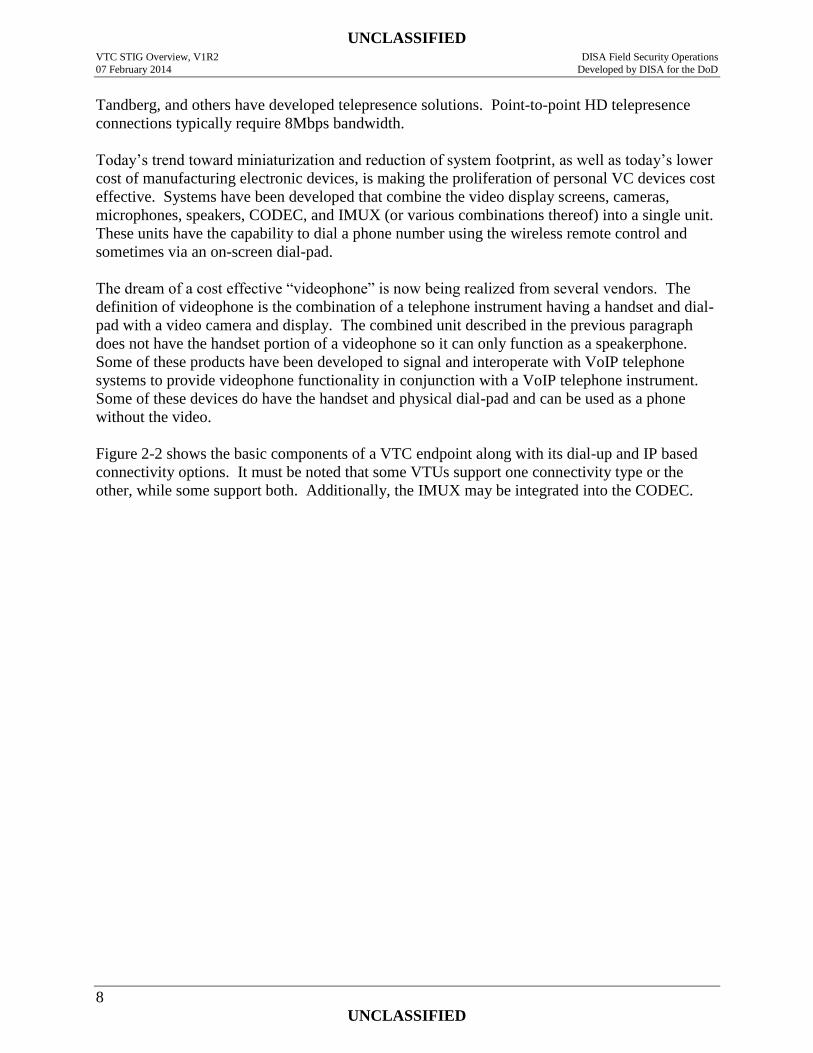
Figure 2-2 shows the basic components of a VTC endpoint along with its dial-up and IP based
connectivity options. It must be noted that some VTUs support one connectivity type or the
other, while some support both. Additionally, the IMUX may be integrated into the CODEC.
UNCLASSIFIED VTC STIG Overview, V1R2 DISA Field Security Operations
07 February 2014 Developed by DISA for the DoD
9
UNCLASSIFIED
Figure 2-2. VTC Endpoint Components and Connections
In addition to a room based system as described above, a VTU can take various forms as follows:
“Integrator systems” consist of the individual piece parts used to implement built in room
based systems as described above.
Mobile “Large Room” or “Small Room / executive” systems can include one or two
video monitors, including speakers, mounted on a cart or pedestal. These are typically
packaged systems. The size of the monitors used dictates the type of system (large vs.
IP Network
LAN / WAN
Audio & Video
EIA-530
Dialing
Info Only EIA-366
NxISDN H.320
IMUX (Inverse
MUX)
VTC
CODEC
Video OUT
Audio OUT
Presentation & External Monitor IN
Audio IN
Video IN
Whiteboard IN
Camera Control
Wired System Control – PC or Room AV
Control
Wireless IR System Control
& Configuration
H.323 or SIP & RTP
Optional Remote Control & Configuration Management
B
Transport Options: ISDN and / or IP
A and / or B
Local Configuration Via Serial port or
Ethernet/IP
Ethernet/IP Port
DSN or PSTN or local PBX
(TDM - Circuit Switched
Network )
A
B
Note: The local VTC system control mechanisms may also control the far
end camera and microphone
UNCLASSIFIED VTC STIG Overview, V1R2 DISA Field Security Operations
07 February 2014 Developed by DISA for the DoD
10
UNCLASSIFIED
small/executive). Some of these systems have the CODEC and IMUX mounted
separately in the base cabinet with the camera on top of the display. Others utilize a set-
top VTU (combined CODEC and IMUX) as described next.
A Set-Top VTU integrates the CODEC/IMUX, camera, microphone, and sometimes the
speaker(s) into a single unit. These are available for use with customer provided
monitor(s) and speaker(s). These devices are designed to sit on top of the monitor(s),
ergo their name.
Desktop VTUs combine all the parts of the VTC system into a single device that looks
like and is typically the size of a PC workstation LCD display or small flat screen
television. These appliances are small enough to sit on the user’s desk, ergo the name
Desktop VTU.
Videophone: Some desktop VTUs include a telephone dial-pad and integrate with a
VoIP telephone system. Such a device is called a videophone.
PC based VTU or soft-VTU: A PC workstation can function as a VTC endpoint using a
software application along with additional accessories or peripherals. These applications
in combination with the PC workstation and its peripherals can be called a soft-VTU or
PC soft-VTU. The PC workstation can be a portable PC (i.e., laptop, etc). The
communications are typically carried over an IP based network, while some applications
are bundled with a PC adaptor card that is an ISDN interface. Such an interface card may
also contain a dedicated CODEC. These applications typically use a USB connected
camera (i.e., “webcam”) along with the PCs native video monitor, sound card,
microphone, and speakers. Microphone(s) and/or speaker(s) can be embedded devices as
found in a portable PC or PC monitor, while they can also be external stand alone
devices. For better audio quality, some higher quality webcams include a high quality
microphone. The microphone and speaker(s) can also be contained in a headset which
can provide some enhanced audio confidentiality. Cameras have typically been stand
alone devices; however, they are also being embedded in laptop screens. While the stand
alone camera can be a simple USB webcam it can also be a more sophisticated device
such as those produced by VTC system vendors. PC workstation VTC applications go by
different names. Confusingly, some vendors market their PC based solutions as “desktop
video systems” or “desktop VTC” since it integrates with the Windows operating system
“desktop”. This is a misnomer which confuses them with hardware based devices that sit
on a desk (i.e., desktop VTUs) and are also called desktop VTC units. Names like “PC
VTC”, soft-VTC, or “Personal VTC” are more appropriate for these software based
VTUs. A soft-VTU is much like a PC soft-phone; a software application that runs on a
personal computer and uses the computer’s resources and peripherals to provide the voice
telephone service. Other PC based applications such as unified communications and/or
collaboration suites are subject to the same or similar requirements since they typically
include video conferencing, as well as telephone capabilities.
UNCLASSIFIED VTC STIG Overview, V1R2 DISA Field Security Operations
07 February 2014 Developed by DISA for the DoD
11
UNCLASSIFIED
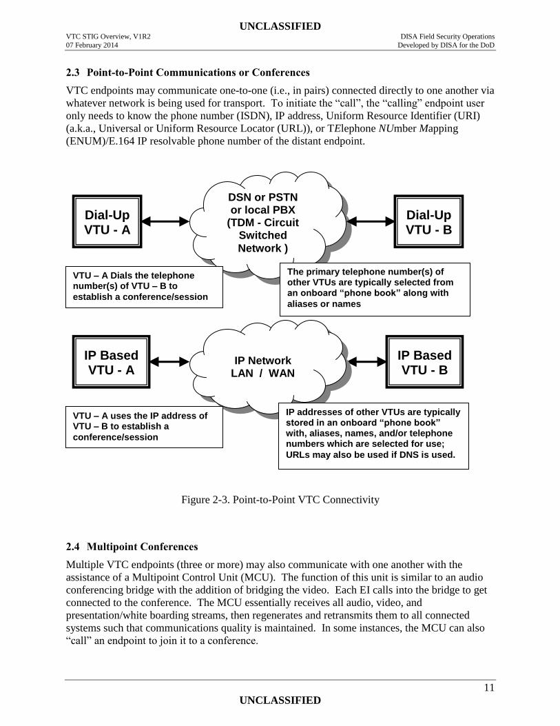
2.3 Point-to-Point Communications or Conferences
VTC endpoints may communicate one-to-one (i.e., in pairs) connected directly to one another via
whatever network is being used for transport. To initiate the “call”, the “calling” endpoint user
only needs to know the phone number (ISDN), IP address, Uniform Resource Identifier (URI)
(a.k.a., Universal or Uniform Resource Locator (URL)), or TElephone NUmber Mapping
(ENUM)/E.164 IP resolvable phone number of the distant endpoint.
Figure 2-3. Point-to-Point VTC Connectivity
2.4 Multipoint Conferences
Multiple VTC endpoints (three or more) may also communicate with one another with the
assistance of a Multipoint Control Unit (MCU). The function of this unit is similar to an audio
conferencing bridge with the addition of bridging the video. Each EI calls into the bridge to get
connected to the conference. The MCU essentially receives all audio, video, and
presentation/white boarding streams, then regenerates and retransmits them to all connected
systems such that communications quality is maintained. In some instances, the MCU can also
“call” an endpoint to join it to a conference.
DSN or PSTN or local PBX
(TDM - Circuit Switched
Network )
IP Network
LAN / WAN
Dial-Up VTU - A
Dial-Up VTU - B
IP Based VTU - A
IP Based VTU - B
VTU – A Dials the telephone number(s) of VTU – B to
establish a conference/session
VTU – A uses the IP address of VTU – B to establish a
conference/session
The primary telephone number(s) of other VTUs are typically selected from an onboard “phone book” along with
aliases or names
IP addresses of other VTUs are typically stored in an onboard “phone book” with, aliases, names, and/or telephone numbers which are selected for use;
URLs may also be used if DNS is used.
UNCLASSIFIED VTC STIG Overview, V1R2 DISA Field Security Operations
07 February 2014 Developed by DISA for the DoD
12
UNCLASSIFIED
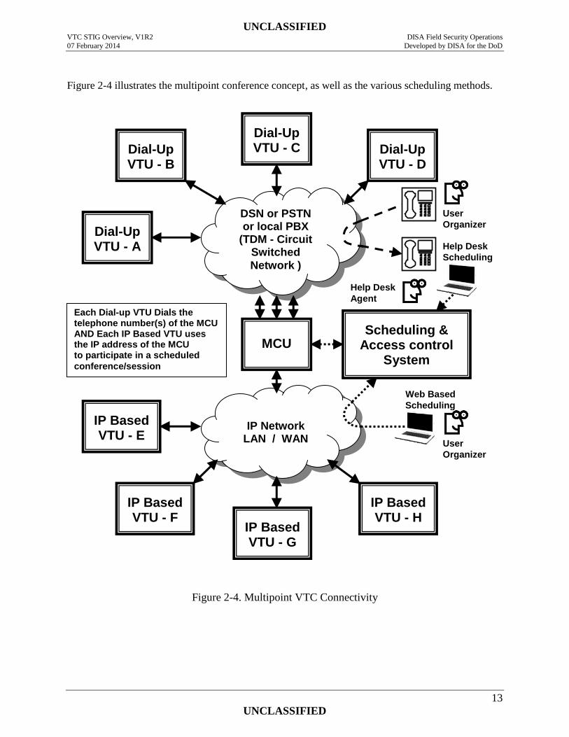
In addition to the MCU, H.323 gatekeepers provide MCU access control and authentication of IP
based endpoints. Conference scheduling/reservation/registration systems are used in conjunction
with the gatekeeper such that the MCU resources are controlled and not overloaded. The
scheduling/reservation/registration systems are accessed via a helpdesk operator or directly by
the conference organizer using a web browser on their workstation. Typically, endpoints must
be pre-registered with the gatekeeper before being able to gain access to the MCU and join
conferences. Organizers must also be registered with the scheduling system.
Some VTC endpoint CODECs have an integrated MCU that can support a limited number of
endpoints (typically four to six). Some of these MCUs can also conference in audio only
telephone calls. Bandwidth requirements of course are higher for the endpoint hosting a
multipoint conference in this manner.
UNCLASSIFIED VTC STIG Overview, V1R2 DISA Field Security Operations
07 February 2014 Developed by DISA for the DoD
13
UNCLASSIFIED
Figure 2-4 illustrates the multipoint conference concept, as well as the various scheduling methods.
Figure 2-4. Multipoint VTC Connectivity
DSN or PSTN or local PBX
(TDM - Circuit Switched
Network )
Dial-Up VTU - A
Dial-Up VTU - D
Dial-Up VTU - C
Dial-Up VTU - B
MCU
Scheduling & Access control
System
IP Network
LAN / WAN
IP Based VTU - E
IP Based VTU - F
IP Based VTU - H
IP Based VTU - G
Each Dial-up VTU Dials the telephone number(s) of the MCU AND Each IP Based VTU uses the IP address of the MCU to participate in a scheduled
conference/session
Web Based
Scheduling
Help Desk
Scheduling
User
Organizer
User
Organizer
Help Desk
Agent
UNCLASSIFIED VTC STIG Overview, V1R2 DISA Field Security Operations
07 February 2014 Developed by DISA for the DoD
14
UNCLASSIFIED
2.5 Ad hoc Conferences
The term “ad hoc” as it relates to VTC refers to conferences being established on the spur of the
moment without scheduling in advance. An example of this is when one user/endpoint calls
another user/endpoint directly in a point-to-point manner. Small ad hoc multipoint conferences
can be supported by many of today’s VTUs using their integrated MCU. These integrated
MCUs are prevalent in today’s desktop and small room/executive conference systems and
typically support four to six VTC endpoints. Some can also conference voice only telephones.
This ad hoc functionality exists since there is generally no need to schedule MCU facilities. Ad
hoc conferences are usually initiated by the originator calling the other participants and joining
them to the conference, however some VTUs can support dial in joining.
Care must be taken by LAN designers and administrators when planning to support a VTU that
will use its MCU capability because of the additional bandwidth requirements. The LAN
connections and equipment supporting the VTU will need to support three (or more) times the
bandwidth needed by a point-to-point call if the capacity of the MCU is utilized. A VTU that
hosts a multipoint conference with three other VTUs operating at a nominal bandwidth of 384
Kbps for each attached VTU will require 1.152 Mbps to support the conference and maintain
good quality audio and video. If a higher definition VTU is used, higher bandwidth is required.
While 384 Kbps is needed for fair quality, many of today’s VTUs default to 768 Kbps.
Additionally, if the access circuit connecting the LAN to the WAN is small, it can be clogged by
this traffic. If the three hosted endpoints are external to the LAN and the LAN is connected to
the WAN with a T1 having 1.544 Mbps, the access circuit capacity is almost filled (exceeded if
768 kbps) this will slow LAN data traffic flowing to and from the WAN while the conference is
in progress while the data traffic could affect quality of the VTC. If the conference is established
between high definition VTUs, the capacity of the access circuit is exceeded. It must also be
noted that some VTUs can also reduce the bandwidth requirement for each of the joined calls, so
that bandwidth requirements are reduced.
This is different from multipoint calls using a central MCU and gatekeeper since the use of the
facilities supporting such calls must be available and typically such usage is scheduled. Some
MCU/gatekeeper systems can support ad hoc multipoint conferences but this capability requires
additional bandwidth into and out of the MCU, as well as additional ports over and above that
required for scheduled conferences. While this is a desired feature in centralized MCU facilities,
this function relies heavily on the availability of MCU resources and over provisioning.
2.6 VTC as a C2 Communications Media
Command and Control (C2) communications requires assured service. The term “assured
service” means that the delivery and availability of information or communications is assured or
guaranteed. In a network, this translates to the allocation of bandwidth and resources on demand
based on precedence consistent with mission needs based on situational awareness. It allows for
preempting bandwidth and resources assigned to lower precedence sessions, so the bandwidth
can be used for higher precedence sessions during a crisis.
Classically, the DoD TDM based telephony network (the DSN) has supported assured service by
having a relatively robust inter-switch trunk (IST) backbone combined with the ability to identify
UNCLASSIFIED VTC STIG Overview, V1R2 DISA Field Security Operations
07 February 2014 Developed by DISA for the DoD
15
UNCLASSIFIED
the priority of a call and pre-empt lower priority calls with higher priority calls both on the line
and trunk sides of a telephone switch. This capability is referred to as Multi-Level Precedence
and Priority (MLPP).
Traditional VTC connections that use ISDN lines provided by a DSN switch and supported by
the DSN backbone trunks can and do support reliable C2 Communications to include precedence
calls by applying MLPP. This is supported in a point-to-point or multipoint configuration
providing the conference is connected within the DSN. The capability is a function of the
network and not the endpoints. Other traditional TDM based networks, such as the PSTN do not
support assured service or MLPP.
IP based networks are not designed to provide assured service. The IP protocol and the
supporting network are designed to provide “best effort” delivery of network traffic. This works
fine for typical data traffic, however, it is not so fine for Real Time Service (RTS) traffic, such as
voice and video. Voice and video require that the packets containing the media streams are
delivered with minimal packet loss, delay (latency), and/or jitter. Packet delivery problems
occur when there is congestion within network elements (equipment) and/or the connections
between the elements. One way that network designers try to overcome the lack of assured
service (or in other words assured delivery of packets) is to beef up the bandwidth handling
capability of the network elements and their interconnections. This is, however, only part of the
solution. Priority delivery of packets can be achieved by the application of Quality of Service
(QOS) and Differential Service Code Point (DSCP) tagging which allows network routers and
switches to forward packets on a priority basis. Another part of the IP based assured service
equation is network redundancy along with the ability of network elements to sense where
problems exist in the network so that packets can be routed around them. Finally, the concept of
“admission control” must be exercised to ensure that no more calls are accepted into the network
than the network can handle without degrading the quality of all calls.
While QOS and DSCP have been available for some time, the implementation of these
capabilities in IP based network elements is relatively new. While newer equipment can provide
and support these capabilities, there is still a lot of older equipment in use today that does not
support them. On the other hand, some endpoints have supported these capabilities for some
time now, waiting for the supporting networks to catch up.
Another capability required for DoD assured service for voice and video is the capability to
signal the priority of a call to call processing elements. This is under development by DISA
engineering and the RTS work group in collaboration with major DoD telephony system
vendors. The capability is supported by an extension of the SIP protocol which is called Assured
Services SIP (AS-SIP).
IP based VTC systems and networks do not provide “assured service”. That is they cannot
guarantee the quality of the video and audio communications and they cannot guarantee that a
connection between VTUs can be established or maintained for the duration of a call. While
some may be capable of using QOS and DSCP tagging, they cannot signal the priority of a call.
UNCLASSIFIED VTC STIG Overview, V1R2 DISA Field Security Operations
07 February 2014 Developed by DISA for the DoD
16
UNCLASSIFIED
As such, IP based VTC should not be relied upon for critical C2 communications that require
assured service or the guarantee that the communication is heard, seen, and understood. This
reality and limitation must be reflected in user training and user agreements.
As the infrastructure and vendor’s products mature, required capabilities are built in, and new
products deployed, assured service will not be an issue.
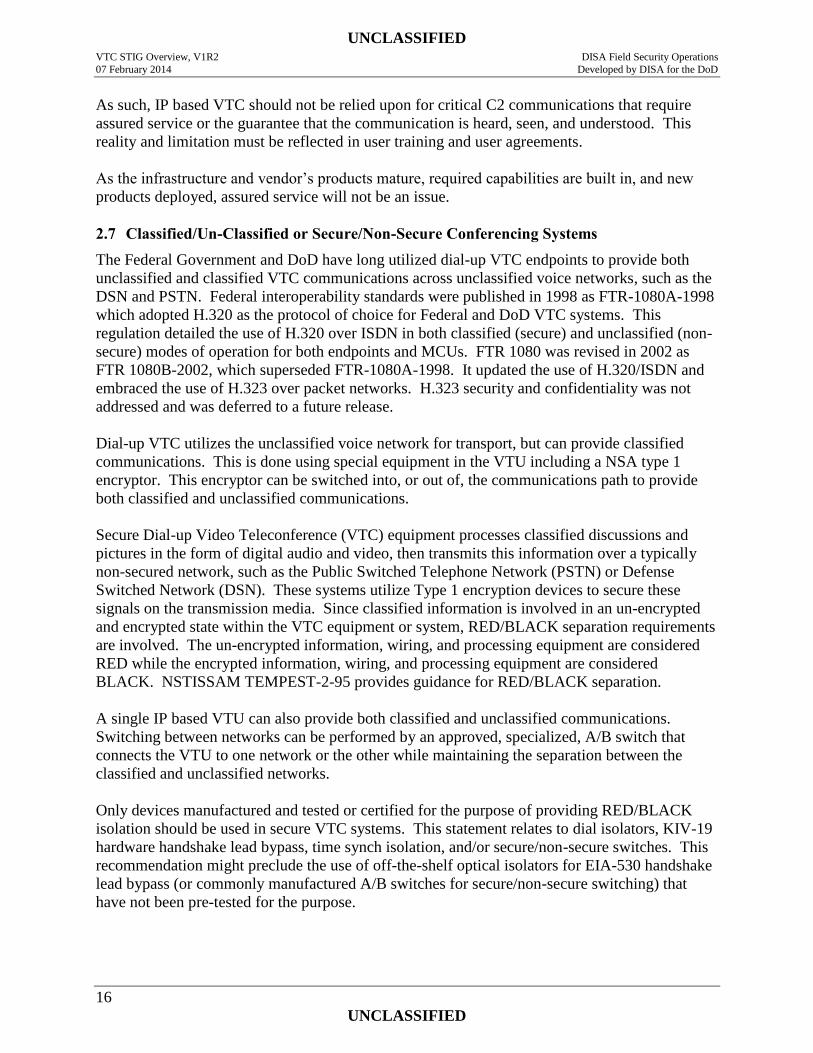
2.7 Classified/Un-Classified or Secure/Non-Secure Conferencing Systems
The Federal Government and DoD have long utilized dial-up VTC endpoints to provide both
unclassified and classified VTC communications across unclassified voice networks, such as the
DSN and PSTN. Federal interoperability standards were published in 1998 as FTR-1080A-1998
which adopted H.320 as the protocol of choice for Federal and DoD VTC systems. This
regulation detailed the use of H.320 over ISDN in both classified (secure) and unclassified (non-
secure) modes of operation for both endpoints and MCUs. FTR 1080 was revised in 2002 as
FTR 1080B-2002, which superseded FTR-1080A-1998. It updated the use of H.320/ISDN and
embraced the use of H.323 over packet networks. H.323 security and confidentiality was not
addressed and was deferred to a future release.
Dial-up VTC utilizes the unclassified voice network for transport, but can provide classified
communications. This is done using special equipment in the VTU including a NSA type 1
encryptor. This encryptor can be switched into, or out of, the communications path to provide
both classified and unclassified communications.
Secure Dial-up Video Teleconference (VTC) equipment processes classified discussions and
pictures in the form of digital audio and video, then transmits this information over a typically
non-secured network, such as the Public Switched Telephone Network (PSTN) or Defense
Switched Network (DSN). These systems utilize Type 1 encryption devices to secure these
signals on the transmission media. Since classified information is involved in an un-encrypted
and encrypted state within the VTC equipment or system, RED/BLACK separation requirements
are involved. The un-encrypted information, wiring, and processing equipment are considered
RED while the encrypted information, wiring, and processing equipment are considered
BLACK. NSTISSAM TEMPEST-2-95 provides guidance for RED/BLACK separation.
A single IP based VTU can also provide both classified and unclassified communications.
Switching between networks can be performed by an approved, specialized, A/B switch that
connects the VTU to one network or the other while maintaining the separation between the
classified and unclassified networks.
Only devices manufactured and tested or certified for the purpose of providing RED/BLACK
isolation should be used in secure VTC systems. This statement relates to dial isolators, KIV-19
hardware handshake lead bypass, time synch isolation, and/or secure/non-secure switches. This
recommendation might preclude the use of off-the-shelf optical isolators for EIA-530 handshake
lead bypass (or commonly manufactured A/B switches for secure/non-secure switching) that
have not been pre-tested for the purpose.
UNCLASSIFIED VTC STIG Overview, V1R2 DISA Field Security Operations
07 February 2014 Developed by DISA for the DoD
17
UNCLASSIFIED
Recently, various organizations with the DoD have expressed a desire to more efficiently utilize
their VTC systems by switching them between networks having different classifications. This
can be accommodated, however, it is imperative that at no time can a VTC system be connected
to networks with different classification levels or dissemination caveats. Switching between
networks having different classification levels is performed by an approved, specialized A/B
switch that meets very specific port isolation and TEMPEST criteria.
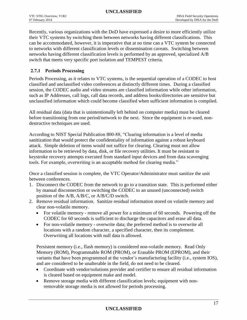
2.7.1 Periods Processing
Periods Processing, as it relates to VTC systems, is the sequential operation of a CODEC to host
classified and unclassified video conferences at distinctly different times. During a classified
session, the CODEC audio and video streams are classified information while other information,
such as IP Addresses, call logs, call data records, and address books/directories are sensitive but
unclassified information which could become classified when sufficient information is compiled.
All residual data (data that is unintentionally left behind on computer media) must be cleared
before transitioning from one period/network to the next. Since the equipment is re-used, non-
destructive techniques are used.
According to NIST Special Publication 800-88, “Clearing information is a level of media
sanitization that would protect the confidentiality of information against a robust keyboard
attack. Simple deletion of items would not suffice for clearing. Clearing must not allow
information to be retrieved by data, disk, or file recovery utilities. It must be resistant to
keystroke recovery attempts executed from standard input devices and from data scavenging
tools. For example, overwriting is an acceptable method for clearing media.”
Once a classified session is complete, the VTC Operator/Administrator must sanitize the unit
between conferences.
1. Disconnect the CODEC from the network to go to a transition state. This is performed either
by manual disconnection or switching the CODEC to an unused (unconnected) switch
position of the A/B, A/B/C, or A/B/C/D switch.
2. Remove residual information. Sanitize residual information stored on volatile memory and
clear non-volatile memory.
For volatile memory - remove all power for a minimum of 60 seconds. Powering off the
CODEC for 60 seconds is sufficient to discharge the capacitors and erase all data.
For non-volatile memory - overwrite data; the preferred method is to overwrite all
locations with a random character, a specified character, then its complement.
Overwriting all locations with null data is allowed.
Persistent memory (i.e., flash memory) is considered non-volatile memory. Read Only
Memory (ROM), Programmable ROM (PROM), or Erasable PROM (EPROM), and their
variants that have been programmed at the vendor’s manufacturing facility (i.e., system IOS),
and are considered to be unalterable in the field, do not need to be cleared.
Coordinate with vendor/solutions provider and certifier to ensure all residual information
is cleared based on equipment make and model.
Remove storage media with different classification levels; equipment with non-
removable storage media is not allowed for periods processing.
UNCLASSIFIED VTC STIG Overview, V1R2 DISA Field Security Operations
07 February 2014 Developed by DISA for the DoD
18
UNCLASSIFIED
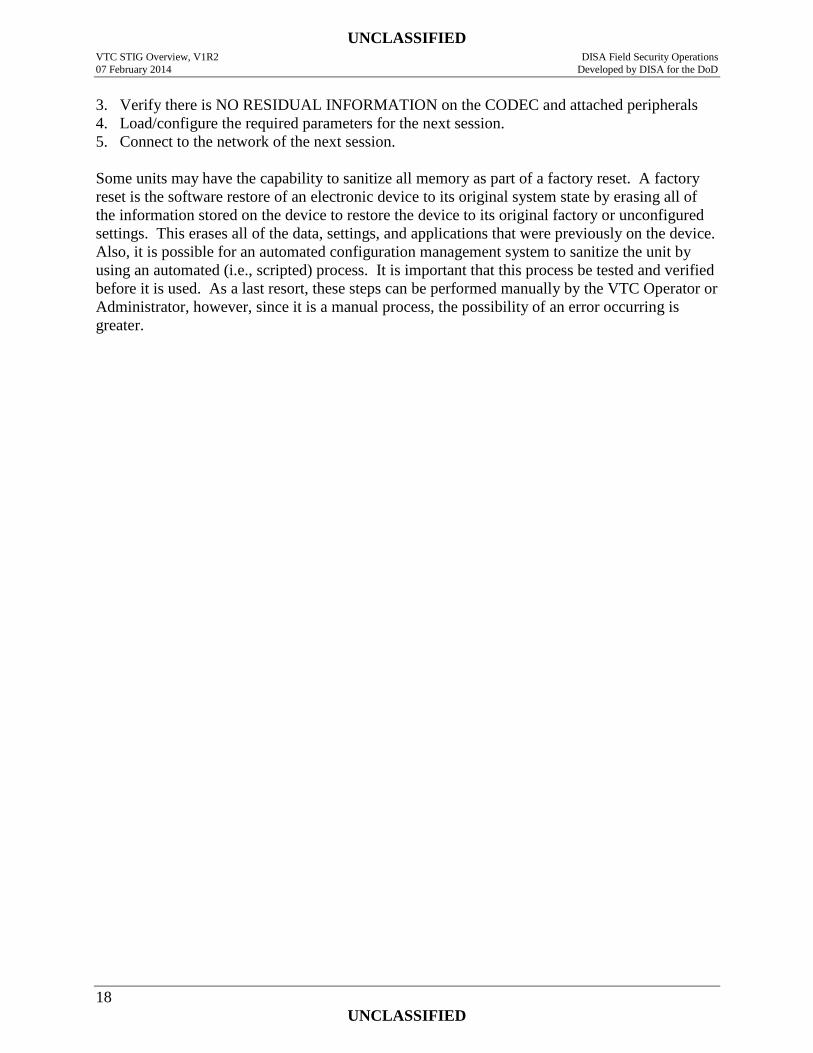
3. Verify there is NO RESIDUAL INFORMATION on the CODEC and attached peripherals
4. Load/configure the required parameters for the next session.
5. Connect to the network of the next session.
Some units may have the capability to sanitize all memory as part of a factory reset. A factory
reset is the software restore of an electronic device to its original system state by erasing all of
the information stored on the device to restore the device to its original factory or unconfigured
settings. This erases all of the data, settings, and applications that were previously on the device.
Also, it is possible for an automated configuration management system to sanitize the unit by
using an automated (i.e., scripted) process. It is important that this process be tested and verified
before it is used. As a last resort, these steps can be performed manually by the VTC Operator or
Administrator, however, since it is a manual process, the possibility of an error occurring is
greater.
UNCLASSIFIED VTC STIG Overview, V1R2 DISA Field Security Operations
07 February 2014 Developed by DISA for the DoD
19
UNCLASSIFIED
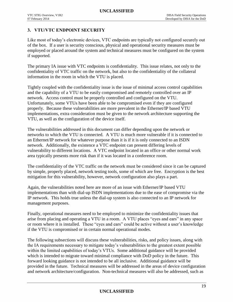
3. VTU/VTC ENDPOINT SECURITY
Like most of today’s electronic devices, VTC endpoints are typically not configured securely out
of the box. If a user is security conscious, physical and operational security measures must be
employed or placed around the system and technical measures must be configured on the system
if supported.
The primary IA issue with VTC endpoints is confidentiality. This issue relates, not only to the
confidentiality of VTC traffic on the network, but also to the confidentiality of the collateral
information in the room in which the VTU is placed.
Tightly coupled with the confidentiality issue is the issue of minimal access control capabilities
and the capability of a VTU to be easily compromised and remotely controlled over an IP
network. Access control must be properly controlled and configured on the VTU.
Unfortunately, some VTUs have been able to be compromised even if they are configured
properly. Because these vulnerabilities are more prevalent in the Ethernet/IP based VTU
implementations, extra consideration must be given to the network architecture supporting the
VTU, as well as the configuration of the device itself.
The vulnerabilities addressed in this document can differ depending upon the network or
networks to which the VTU is connected. A VTU is much more vulnerable if it is connected to
an Ethernet/IP network for whatever purpose than it is if it is only connected to an ISDN
network. Additionally, the existence a VTC endpoint can present differing levels of
vulnerability to different locations. A VTC endpoint located in an office or other normal work
area typically presents more risk than if it was located in a conference room.
The confidentiality of the VTC traffic on the network must be considered since it can be captured
by simple, properly placed, network testing tools, some of which are free. Encryption is the best
mitigation for this vulnerability, however, network configuration also plays a part.
Again, the vulnerabilities noted here are more of an issue with Ethernet/IP based VTU
implementations than with dial-up ISDN implementations due to the ease of compromise via the
IP network. This holds true unless the dial-up system is also connected to an IP network for
management purposes.
Finally, operational measures need to be employed to minimize the confidentiality issues that
arise from placing and operating a VTU in a room. A VTU places “eyes and ears” in any space
or room where it is installed. These “eyes and ears” could be active without a user’s knowledge
if the VTU is compromised or in certain normal operational modes.
The following subsections will discuss these vulnerabilities, risks, and policy issues, along with
the IA requirements necessary to mitigate today’s vulnerabilities to the greatest extent possible
within the limited capabilities of today’s VTUs. Some additional guidance will be provided
which is intended to migrate toward minimal compliance with DoD policy in the future. This
forward looking guidance is not intended to be all inclusive. Additional guidance will be
provided in the future. Technical measures will be addressed in the areas of device configuration
and network architecture/configuration. Non-technical measures will also be addressed, such as
UNCLASSIFIED VTC STIG Overview, V1R2 DISA Field Security Operations
07 February 2014 Developed by DISA for the DoD
20
UNCLASSIFIED
Standard Operating Procedures (SOPs), vulnerability awareness, user/administrator/helpdesk
training, user agreements, and user guides.
In general, when VTC systems are implemented, consideration must be given to mission benefits
weighed against operational risks and the possibility of improper disclosure of information. This
applies to facilities based, desktop based, and PC based systems and devices.
3.1 DoD Access Control and Auditing Policy Compliance
DoD user/administrator account and password requirements are defined by the DoDI 8500.2 IA
control IAIA-1, IAIA-2, IAAC-1, IAGA-1, as well as Cyber Command Tasking Order (CTO)
issuances, as amended, and any current INFOCON modifications. IA controls ECLO-1 and 2
provide policy for system/device logon controls, while IATS-1 and 2 provide policy requiring
DoD Public Key Infrastructure (PKI) certificates along with physical tokens (i.e., Common
Access Card (CAC) or Alternate Logon Token (ALT)) be used for system/device access, user
identification, authentication, and non-repudiation. These policies address individual
user/administrator accounts and user-IDs; two-factor authentication using CAC, other PKI based
tokens (i.e., ALT), or the use of passwords; password strength; password history; password and
account aging and lockout; account lockout for failed logon attempts; removal of unnecessary
accounts; group accounts, and more. IA controls ECPS-1 and ECLP-1 define policy for various
levels of user and administrator authorization based on roles and the principal of least privilege.
Additionally, IA controls ECAT-1, ECAR-1, 2, and 3, as well as ECTP-1 define DoD security
auditing policy. Under these policies, user and administrator actions that could affect security
are to be recorded in a protected security or audit log. These IA controls rely on the successful
implementation of individual user accounts and other required access control measures. Without
individual user accounts and/or identities to which actions can be tied, auditing of
user/administrator actions becomes impossible. Examples of auditable actions include (but are
not limited to) access to the system or device; access to, use of, or activation of services provided
by the system or device; access to files on the system or device to include modification, deletion,
name changes etc.; access to configuration settings along with changes made. These auditing
records are in addition to and separate from traditional telephony CDRs used for accounting
purposes.
3.2 Confidentiality
Both operational controls and technical controls are required to ensure the best possible
confidentiality of conference content (i.e., the information discussed or viewed) and of the
information in the space in which a VTU is installed (i.e., non-conference or “collateral”
information within view of a camera or range of the microphone), as well as the information
contained on a presenter’s workstation (i.e., information contained in files or open windows
other than those being presented to the conference). The following subsections will deal with the
requirements necessary to ensure the confidentiality of non-conference information and
conference content including the media streams. Subsequent sections will discuss and define
additional requirements to help with ensuring this confidentiality. These additional requirements
will address CODEC configuration measures, network configuration measures, and other issues.
UNCLASSIFIED VTC STIG Overview, V1R2 DISA Field Security Operations
07 February 2014 Developed by DISA for the DoD
21
UNCLASSIFIED
3.2.1 Confidentiality of Information in the Physical Environment
The VTU in itself presents a great vulnerability to the confidentiality of information in the
physical environment in which it is installed. The information in question is the “collateral”
information within the audio and video pickup range of the endpoint. The simple introduction of
a VTU (i.e., VTC endpoint) into a room degrades the security posture of that room. This is
because this endpoint places “eyes and ears” in the physical environment. The “eyes” are the
cameras while the “ears” are the microphones. If not properly configured and operated, sensitive
or classified information may be unintentionally disclosed to entities that do not have proper
clearance or a need-to-know. This could be more of a concern in offices and work areas where
sensitive or classified work is performed and discussed than in conference rooms, however, the
vulnerability applies to both areas. This is because sensitive or classified information is not
typically hung on the walls of a conference room, except during a conference, but may be in an
office, cube, or other work area. On the other hand, if a conference room is only used for VTC
conferences, and there are no other meetings held there and the room contains no sensitive or
classified information when not in use, there is little or no vulnerability.
If the endpoint is not properly configured to prevent compromise or unintentional/unauthorized
access, a room can be visually and/or aurally monitored from a remote location, and in some
instances, without detection by the occupants of the space. Non-fixed cameras can be remotely
controlled (i.e., panned, tilted, and zoomed) without the room occupants being aware unless they
spot the movement. A microphone can also be remotely activated. VTC system microphone
sensitivity is very high and can typically pick up a relatively quiet conversation from across a
room. This places occupant activities and conversations at risk of disclosure to unknown
entities. A VTU located in an office space or on a desktop could capture the space occupant’s
conversations, one side of their telephone calls (both sides if a speakerphone is used), and/or
video of the occupant performing his/her regular activities. While this could be considered a
privacy issue, if the workspace is one where sensitive or classified information is used,
discussed, or posted on the wall in view of the camera, this information can also be captured. All
of this captured information can be disclosed to individuals without a validated need-to-know or
proper security clearance. Consideration must be given to the operation and configuration of a
VTU in the context of the physical environment in which it is installed. This consideration must
include answering the question: who’s watching you or who could potentially be watching
and/or listening.
The most common and easiest avenue for unintentional/unauthorized access and/or compromise
of a VTU is via the Ethernet/IP interface. While a VTU can be compromised, as described
above, via ISDN using a combination of “auto answer” and far end camera control, there are
many more ways to do it via the IP interface.
3.2.2 Confidentiality while the VTU is Inactive/in Standby
For the purpose of this document, a VTU being “inactive” means it is NOT actively participating
in a VTC session but it is powered on. This could be considered a “standby” mode of operation.
Conversely, a VTU being “active” means it is actively participating in a VTC session.
“Inactive” could include both “standby” and “sleep” modes of operation. Sleep mode is a power
conservation and semi disabled state that the VTU might enter after being on standby for a
UNCLASSIFIED VTC STIG Overview, V1R2 DISA Field Security Operations
07 February 2014 Developed by DISA for the DoD
22
UNCLASSIFIED
period of time. While in sleep mode, the VTU is still minimally powered and thereby could be
remotely accessed, compromised, or easily activated.
A VTU that is powered on and in an “inactive” mode but is not appropriately disabled (and
configured) presents a vulnerability to the following:
Meetings held in a conference room in which a VTU is installed but that does not require
the use of the VTU to participate in a VTC.
Activities and information located in an office or other work area in which a VTU is
installed that is within range of the VTU when the VTU is not participating in a VTC.
3.2.2.1 Power-Off the VTU When Inactive
When the VTU is not active, it is best to power it off to mitigate the issues addressed here. This
may not be practical, particularly if the VTU is intended, or required, to receive un-scheduled
incoming calls or is to be remotely managed/monitored in an un-scheduled manner. Receiving
un-scheduled incoming calls that are automatically answered is, in itself, a vulnerability. This is
an issue for IP and ISDN connected systems if auto-answer is on. The auto-answer feature is
discussed later. Remote access and monitoring are also vulnerabilities due to the lack of strong
access control mechanisms and the ease with which a VTU can be compromised if it is
connected to an IP network. These vulnerabilities are discussed later. The point of this and the
next requirement is to disable the capability of the VTU to “see and hear” information and
activities located or occurring near the VTU when it is not actively participating in a call. While
these vulnerabilities are of particular concern in an office or other work area, it may be of less
concern in a conference room except if meetings occur in the facility that do not require the use
of the VTC system.
3.2.2.2 Disable the VTU When Powered & Inactive
In the event that mission requirements dictate the VTU be in a powered-on state when inactive
(thereby overriding RTS-VTC 1020), other measures are required to mitigate the vulnerability of
possible VTU compromise and establish a defense in depth posture. These mitigations are: 1) to
mute the microphone and 2) to disable the viewing capability of the camera in some manner. If
the camera is movable, it could be aimed at the nearest corner of the room, however, this is no
mitigation if the VTU is compromised and the camera can be re-aimed into the room. The best
mitigation for the camera is to cover the lens. This is applicable to both movable and fixed
cameras.
3.2.2.3 Sleep Mode
Sleep mode is the power conservation and semi disabled state that some VTUs can enter after
being on standby for a period of time. While in sleep mode, the VTU is still minimally powered
and thereby could be remotely accessed, managed, compromised, or easily activated. For the
purpose of our discussions, sleep mode is different from standby mode by the fact that in standby
mode, by our definition, the VTU is not actively participating in a call but is ready to receive or
place a call. Sleep mode is a semi off state whereby most functions of the VTU are disabled to
conserve power. If used to mitigate vulnerabilities and not just conserve power, sleep mode
must have the characteristics noted in RTS-VTC 1027.00.
UNCLASSIFIED VTC STIG Overview, V1R2 DISA Field Security Operations
07 February 2014 Developed by DISA for the DoD
23
UNCLASSIFIED
3.2.2.4 Incoming Call Notification
In the event that mission requirements dictate the VTU be in a powered-on state when inactive,
the VTU becomes available to receive incoming calls (except possibly when sleeping).
Additionally, if a VTU is connected to an IP network, it may be capable of receiving incoming
calls while active. When a VTU receives an incoming call, the normal operation is that a
notification of the incoming call is provided both audibly and visually. The visual notification
typically includes a display of the source of the call. This can be a phone number or IP address.
This information should be accompanied by an identification of the caller. While the source
information is typically available from the network, the identity of the calling party associated
with that information is typically contained in a locally accessible directory. If the source
information is in the directory, the associated identity information is located and added to the
display or displayed by itself. This directory is typically on the VTU or can be on a locally
associated management or directory server. Directories must therefore be kept up to date with
user information related to other VTUs with which any given VTU is expected to communicate.
Ideally, the full identity of the caller is sent from the calling system for display on the called
system even if there is no local directory entry.
Based upon the displayed information, the user of the VTU can make an informed decision and
take appropriate action to answer the call or not. Users must be trained to not answer calls from
unknown sources in the event doing so could disclose sensitive or classified information in the
area of the VTU or while engaged in a VTC session.
3.2.2.5 Auto-Answer Availability
Some VTC endpoints have a user selectable feature that provides the capability to automatically
answer an incoming call. This would be akin to your speakerphone picking up a call each time
the phone rang allowing an ongoing conversation to be heard by the caller. This feature, if
activated, is highly detrimental to the confidentiality of information in a room in which a VTU is
installed. In fact, a security incident could result from “auto-answer” being enabled. Such
would be the case in the event a VTU automatically answered a call when a classified meeting or
discussion (not via VTC) was being held in a conference room or an office having VTC
capability. The auto-answer feature must not be activated by a user unless the feature is required
to satisfy mission requirements. Furthermore, users must be trained in the vulnerabilities
associated with the auto-answer feature and in its proper use if it is to be used. The ideal
mitigation for this vulnerability is for the auto-answer feature to not be supported by the VTU or
there be an administrator setting that can disable the feature preventing a user from activating it.
3.2.2.6 Auto-Answer Use Mitigations
In the event the auto-answer feature is approved for use or cannot be administratively disabled
and thus is available for users to activate, several mitigating requirements must be met. The first
of these is that the user(s) to which the feature is available must be trained in its proper use and
in the vulnerabilities it presents because the user is the one that must implement the operational
mitigations. The second is the VTU must answer the call with the microphone muted and with
the camera covered or disabled. This will prevent an ongoing conversation from being heard and
room activities seen by the caller. This will also prevent the room from being audibly and
visually monitored if a call is automatically answered when the VTU is un-attended. The third
UNCLASSIFIED VTC STIG Overview, V1R2 DISA Field Security Operations
07 February 2014 Developed by DISA for the DoD
24
UNCLASSIFIED
mitigating requirement is that the user must be notified that the VTU has received and answered
a call such that the user may be viewed if the camera is not/cannot be covered or listened to if the
microphone is not/cannot be muted. This means that a noticeable visual indication must be
provided and any available audible signal must be maintained at an audible level so it can be
heard.
3.2.3 Confidentiality While the VTU is Active
As noted earlier, a VTU being “active” means it is actively participating in a VTC session.
There are several issues to be aware of or vulnerabilities to be mitigated while the VTU is active.
These are discussed in the following subsections.
3.2.3.1 Audio Pickup and Broadcast SOP
Microphones used with VTC systems and devices are designed to be extremely sensitive such
that people speaking anywhere within a conference room is picked up and amplified so they can
be heard clearly and understood at the remote location(s) on the call. This same sensitivity is
included in VTUs that are used in office spaces. This has one disadvantage. The microphones
can pick up sidebar conversations and other conversations that have no relationship to the
conference or call in progress. Likewise, in an open area, received conference audio can be
broadcast to others in the area that are not part of the conference, and possibly should not be
exposed to the conference information for need-to-know reasons. Speakerphones exhibit a
similar vulnerability. This is the same confidentiality vulnerability posed to information in the
environment as discussed above with the added twist that the conference audio is vulnerable to
others in the environment. While this is more of an issue in environments where classified
conversations normally occur, it is also an issue in any environment. This is of particular
concern in open work areas or open offices where multiple people work in near proximity. Users
or operators of VTC systems of any type must take care regarding who can hear what is being
said during a conference call and what unrelated conversations can be picked up by the sensitive
microphone(s). Where a VTU is used by a single person in an open area, a partial mitigation for
this could be the use of a headset with earphones and a microphone. While this would limit the
ability of others to hear audio from the conference and could also limit the audio pickup of
unrelated conversations, it may not be fully effective. In some instances, such as when a VTU is
located in a SCIF, a Push-to-Talk (PTT) handset/headset may be required.
This SOP should take into account the classification of the area where the VTU is installed, as
well as the classification and need-to-know restraints of the information generally communicated
via the facility or specific VTU. Along with those mentioned above, measures should be
included, such as closing office or conference room doors, muting of microphones before and
after conference sessions and during conference breaks, volume levels in open offices as well as
muting the microphone when not speaking.
3.2.3.2 Information In View Of the Camera SOP
Care must be taken by conference room and office based VTU users not to inadvertently display
information of a sensitive or classified nature that is not part of the conference proceedings while
the VTU is active. This can happen if information in the form of charts, pictures, or maps are
displayed on a wall that is within the viewing range of a camera. The pan, tilt, and zoom
UNCLASSIFIED VTC STIG Overview, V1R2 DISA Field Security Operations
07 February 2014 Developed by DISA for the DoD
25
UNCLASSIFIED
capabilities of the camera(s) must be considered. One may think something is out of range, but it
may not be due to camera capabilities and video enhancement capabilities for captured frames.
Inadvertent displays of information could also happen if the information is laying on a desk or
table unprotected.
3.2.3.3 Incoming Calls While In a Conference
As discussed above, whether active or inactive, a VTU must display the source of an incoming
call and the caller’s identity so the user can decide to answer the call or not. This decision must
also be based upon what information would be made available to the caller when the call is
answered. The information that would be placed at risk is what can be picked up in the physical
area of the VTU or what is being carried by the conference in which it is participating.
If the VTU is participating in a conference already, answering a call while in a conference would
activate the VTU’s integrated MCU and join the caller to the conference. The possibility of an
incoming call being automatically joined to a meeting in progress in this manner places the
confidentiality of that meeting at risk. The caller could become a participant of a meeting to
which they were not invited and subsequently receive sensitive or classified information for
which the caller may or may not have a need-to-know or appropriate security clearance.
As with a VTU in standby mode, an “auto-answer” feature is of great concern during a VTC
session. A VTU must be configured in such a way that it cannot automatically answer a call and
join the call to an active session without some form of access control. Either user intervention or
a properly managed “local meeting” password is required to join such an incoming call to an
active session. In some instances the “do-not-disturb” feature may be used by the user to block
such calls by returning a “busy” signal. The capability of joining a conference on a VTU using
its integrated MCU through the use of a “local meeting” password must be used only when the
VTU user needs to pre-schedule and host a multipoint conference on his/her VTU. This
capability must not be available at all times. The VTU should have the capability to disable this
kind of access when it is not needed. Local meeting passwords must be used one time and not
repeated. This requirement is discussed later.
3.2.3.4 Disable VTU Remote Monitoring
Some VTC endpoints support the capability for an administrator or facilitator to view or monitor
the VTU location (i.e., the room where it is located) remotely via a web interface. Some VTUs
provide this feature via snapshots, while others provide the capability in real time. This feature
can also include control capabilities and is used for troubleshooting, checking endpoints and
rooms for operational readiness, or active monitoring of a call for quality control, etc. This
capability poses a confidentiality issue for active conferences and the information in the
proximity of the endpoints. Remote monitoring must be disabled as a general rule unless
required to satisfy validated and approved mission requirements to prevent unauthorized access.
This discussion also applies to administrator’s endpoints fully participating in a call for reasons
of troubleshooting or quality control.
UNCLASSIFIED VTC STIG Overview, V1R2 DISA Field Security Operations
07 February 2014 Developed by DISA for the DoD
26
UNCLASSIFIED
3.2.3.5 VTU Remote Monitoring Password
Activation and use of remote monitoring and control features, such as those discussed here must
be protected by access control. Minimally, this must be the administrator password, however,
access to this feature should not give full administrator access.
3.2.3.6 Remote Monitoring Notification
Monitoring of a conference or VTC system can be performed in various ways. This can be by
accessing the monitoring capabilities of a particular VTU via IP as discussed above, or using a
capability of a centralized MCU, or an administrator or “operator/facilitator” can participate in a
conference using a VTU. No matter how monitoring is being performed, participants in a call
must be notified or be made aware that the call is being monitored by someone that is not a direct
participant of the call or conference who therefore may not have a need-to-know regarding the
conference information. This is particularly of concern if the monitored conference contains
classified information. If the monitoring is done by remotely accessing a VTU, typically, an
automated notification is displayed on the VTU being monitored. This indication should also be
displayed on all connected endpoints. Minimally, there is an SOP that requires the presence of a
person monitoring a conference be announced to the conferees.
3.2.3.7 Remote Monitoring Operator Clearance
Administrators or “operators/facilitators” that perform monitoring as discussed in this section
must have an appropriate security clearance commensurate with or higher than the classification
level of the system and/or the information to which they are exposed.
Additional requirements and/or clarifications regarding remote monitoring features and activities
may appear in a future release of this or a related STIG. Some of these may specifically address
classified conferences. One such requirement may be the use of a tone to announce the presence
of monitoring.
3.2.3.8 Far End Camera Control
Many VTC endpoints support Far End Camera Control (FECC). This feature uses H.281
protocol which must be supported by both VTUs. Typically, this is only available during an
active VTC session but could be available if the VTU is compromised or if a call is
automatically answered. Allowing another conference attendee to take control of your camera
can place the confidentiality of non conference related information at risk. FECC should be
disabled to prevent the control of the near end camera by the far end unless required to satisfy
validated mission requirements.
3.2.4 Conference Media and Signaling Confidentiality
DoDI 8500.2 IA control ECCT-1 for “Enclave and Computing Environment/Encryption for
Confidentiality (Sensitive Data in Transit) states “Unclassified, sensitive data transmitted
through a commercial or wireless network are encrypted using NIST-certified cryptography (see
also DCSR-2).” [ed. DCSR-2 Specified Robustness – Medium; Type-3]
UNCLASSIFIED VTC STIG Overview, V1R2 DISA Field Security Operations
07 February 2014 Developed by DISA for the DoD
27
UNCLASSIFIED
DoDI 8500.2 IA control ECCT-2 for “Enclave and Computing Environment/Encryption for
Confidentiality (Classified Data in Transit) states “Classified data transmitted through a network
that is cleared to a lower level than the data being transmitted are separately encrypted using
NSA-approved cryptography (See also DCSR-3).” [ed. DCSR-3 Specified Robustness – High;
NSA Type-1]
Furthermore, DoDI 8500.2 IA control ECNK-1 for Enclave and Computing
Environment/Encryption for Need-To-Know states “Information in transit through a network at
the same classification level, but which must be separated for need-to-know reasons, is
encrypted, at a minimum, with NIST-certified cryptography. This is in addition to ECCT. (ed.
Encryption for confidentiality data in transit).”
DoDI 8500.2 IA control ECCT-2 primarily applies to classified data traversing the IP WAN (i.e.,
Defense Information Systems Network (DISN)) or other transport media, such as a TDM based
circuit switched network. The IP WAN is protected by NSA type 1 encryptors that bulk encrypt
the circuits or links that interconnect the local classified enclaves or LANs. Separation of traffic
for need-to-know purposes, while traversing these classified IP LANs and links, is covered by IA
control ECNK-1. On the other hand, Dial-up VTUs that process classified information
implement ECCT-2 by utilizing a NSA type 1 encryptor at each VTU and each port of a MCU if
applicable.
The “NIST-certified cryptography” referred to by these IA controls is cryptography validated to
Federal Information Processing Standard (FIPS) 140-2 as validated through the National Institute
of Standards (NIST) Cryptographic Module Validation Program (CMVP).
In the early days of VTC, CODECs did not support confidentiality of the media or signaling
streams directly. As security and conference confidentiality have become an IA issue in recent
years, VTU vendors have standardized on DES and then AES as encryption standards for VTC
media streams. H.235 has been developed to help to secure the signaling protocols used in the
H.323 suite of protocols.
3.2.4.1 Encryption of Signaling and Signaling Security
The International Telecommunications Union (ITU) has developed H.235, which is the security
recommendation for H.323 and other H.245 based systems. This recommendation provides for
user identification rather than device identification. User identification can be simple or utilize
Public Key Infrastructure (PKI). The latter being the goal of the DoD PKI policy. H.235 also has
the capability and purpose of negotiating encryption and key exchange.
H.235 security ensures the authentication of each endpoint and the integrity of messages. The
basis of the security process is the shared secret between the endpoint and the gatekeeper. This
shared secret can be either a password or a key. Only the endpoint and the gatekeeper know the
shared secret. Authentication and Integrity are achieved by encrypting part of the entire message
using the shared secret. Whenever an endpoint sends a message to the gatekeeper, the endpoint
encrypts the message using the password. The gatekeeper authenticates the message using the
same password. If one of the parties does not have the correct password, the authentication fails
and the call is rejected.
UNCLASSIFIED VTC STIG Overview, V1R2 DISA Field Security Operations
07 February 2014 Developed by DISA for the DoD
28
UNCLASSIFIED
3.2.4.2 Encryption of Media
Most if not all VTC media traffic is considered to be sensitive information requiring protection
under the IA controls discussed above. ECNK-1 applies to such traffic while traversing any
network with any classification level (i.e., NIPRNet, SIPRNet, JWICS). ECCT-1 specifically
applies to such traffic traversing any commercial or wireless network (i.e., Internet, 802.ll
WLAN, or cellular network) but should also be considered as a requirement for traversal of the
NIPRNet.
At minimum, and if supported by both endpoints in a point-to-point conference, or all endpoints
and the MCU in a multipoint conference, encryption must be used for media encryption. The
encryption algorithm required is AES for two reasons. The first is that DES has been cracked
and is no longer approved for Federal Government use, and the second is to satisfy DoDI 8500.2
IA control ECCT-1 and ECNK-1; Type-3 encryption of data in transit for confidentiality and
need-to-know.
Unfortunately, there is a lot of legacy VTC gear in use today that either only supports DES or
has no encryption capability at all. To support this situation, newer CODECs typically have
three encryption options ON, OFF, or automatic/negotiate. The preferred setting is ON and
should be used if it is known that all other VTUs that a VTU needs to communicate with support
encryption. Auto/negotiate is the preferred setting if this is not known.
In reality, however, any encryption, AES or DES, is better than no encryption at all and must be
used if available. Many VTUs provide the capability to select the type of encryption used and
may also provide an auto-negotiate mode. If it is known that all other VTUs that a VTU needs to
communicate with uses AES encryption, AES should be selected. DES should never be selected
if AES is available. Auto/negotiate is the preferred setting if it is not known which algorithm the
other VTUs will use.
3.2.4.3 FIPS 140-2 Validated Encryption
The current DoD requirement for encryption is that the encryption module, which includes a
FIPS 197 validated encryption algorithm plus “approved functions” (i.e., key management and
sharing/distribution functions), be NIST validated to FIPS 140-2. It must be noted that legacy
equipment validated to FIPS 140-1 may still be used and FIPS 140-3 is in development.
While many VTU vendors support AES, they have only validated the algorithm to FIPS-197, if
at all. This does not meet the FIPS 140-2 requirement because the additional “approved
functions” have not also been addressed.
3.2.4.4 Encryption Indicator
In support of the need for encryption and the need for the VTU user to be aware that, in fact,
his/her conference session is being encrypted, the VTU must display an indicator that encryption
is indeed occurring.
UNCLASSIFIED VTC STIG Overview, V1R2 DISA Field Security Operations
07 February 2014 Developed by DISA for the DoD
29
UNCLASSIFIED
3.2.4.5 User Validation Of Encryption
When encryption is enabled via automatic/negotiate, and one endpoint does not support
encryption or supports DES and not AES, the entire conference defaults to the lower capability
level. This is not acceptable for some conferences depending upon the sensitivity of the
information discussed or presented. As noted above, the stated DoD IA controls require
encryption. To ensure this requirement is met, when it is unknown whether all endpoints in a
conference support encryption and whether it is turned on, the VTU user must provide the final
check that encryption is being used. If a conference is to be encrypted, the user must check that
all participants are using encryption and have enabled the encryption on their devices. When the
conference has begun, the user must ensure the conference is encrypted. The alternate to this is
to exclude the endpoint that does not support the required encryption or not proceed with the
conference session.
3.3 VTC Endpoint Access Control
DoD IS access control requirements for users and administrators are defined in various IA
controls in DoDI 8500.2. Account and password requirements are defined by the IA controls
IAIA-1, IAIA-2, IAAC-1, IAGA-1, as well as Cyber Command CTOs, and any current
INFOCON modifications. Additionally, IA controls ECLO-1 and 2 provide policy for
system/device logon, while IATS-1 and 2 provide policy requiring the use of DoD PKI
certificates along with CAC/ALT are used for system/device access. These policies address
individual user/administrator accounts and passwords, password strength, password history,
password and account aging and lockout, account lockout for failed logon attempts, group
accounts, and more.
Typically, VTC CODECs do not support most of these requirements on all access points, if at
all. Thus, they are easily compromised.
There are typically two methods of accessing a VTU for operational control or administrative
reasons. The first is using the hand-held remote control, which is similar to a television remote
control. The second is using one of the connections on the CODEC to directly connect an AV
system control panel or a PC. The ports used for these purposes are typically the serial (EIA-
232) port or the Ethernet port. Additionally, a PC, centralized management server, or emergent
AV control panel can be used across an Ethernet/IP network. The EIA-530 and ISDN
connections typically do not support operational control or administrative functions; however, at
least one vendor provides the capability of upgrading CODEC software over ISDN.
The following subsections will discuss access control requirements regarding VTC endpoints.
3.3.1 Change Default Passwords
DoDI 8500.2 IA controls IAIA-1 and IAIA-2 state, in part: “Ensure all factory set, default,
standard or well-known user-IDs and passwords are removed or changed.”
Factory default, well-known, and/or manufacturer backdoor accounts and their associated
passwords provide easy unauthorized access to system/device. Leaving such accounts and
passwords active on a system/device makes it extremely vulnerable to attack and/or other
UNCLASSIFIED VTC STIG Overview, V1R2 DISA Field Security Operations
07 February 2014 Developed by DISA for the DoD
30
UNCLASSIFIED
unauthorized access. As such, they need to be removed, changed, renamed, or otherwise
disabled.
Also covered by this policy are “community strings”, which act as passwords for monitoring and
management of network devices and attached systems via SNMP. The universal default SNMP
community strings are “public” and “private” and are well-known.
Default access for VTC operation, local and remote control, and management/configuration
purposes is typically unrestricted or minimally protected by well-known and well published
default passwords. It has been demonstrated that not changing these passwords is the most
common cause of VTC system compromise, making RTS-VTC 2020.00 one of the most
important requirements in this STIG.
3.3.2 Password Display during Logon
As any information is entered on a keyboard, the keyboard sends each keystroke to the
processing unit which then, typically, echoes the character represented by the keystroke to the
display device as feedback to the system’s user. Such echoing is done in what is called “clear
text” in that what was entered can be read. This process is used for normal typing, but must be
changed when entering passwords. When passwords are displayed (echoed) during logon, the
risk of password compromise is increased and password confidentiality is greatly reduced. If the
password is displayed during logon, it can easily be compromised through the use of a simple
technique of shoulder surfing i.e., a third party witnessing the logon (other than the system or
user/administrator) could view the echoed password and remember it or write it down. This
could also happen through surveillance methods. This presents a major vulnerability to the
security or confidential nature of the password. To mitigate this, when entering a password, the
characters that are echoed to the display must be something other than the clear text characters.
Typically, an asterisk or other punctuation character is used to replace the actual characters in an
echoed password. The prevention of shoulder surfing is in support of DoDI 8500.2 IA control
IAIA-1’s requirement to protect passwords from disclosure.
3.3.3 Password/PIN Strength or Complexity
DoD policy mandates the use of strong passwords. IA control IAIA-1&2 item 2 states “For
systems utilizing a logon ID as the individual identifier, ensure passwords are, at a minimum, a
case sensitive 8-character mix of upper case letters, lower case letters, numbers, and special
characters, including at least one of each (i.e., emPagd2!).”
DoDI 8500.2, therefore, sets the minimum complexity requirement for a character based
password. This minimum complexity is reiterated by CJCSM 6510.01, C-A, Section 4 which
adds the recommendation that “If technically feasible, 12 to 16 characters using a mix of all four-
character sets is recommended (i.e., 14 characters using a mix of all four-character sets in the
first 7 characters and the last 7 characters).”
In some circumstances, policies change is the result of Cyber Command CTO issuances which
set the minimum password complexity (for systems not using DoD PKI) to 9 characters with “a
mix of at least two lowercase letters, two uppercase letters, two numbers, and two special
UNCLASSIFIED VTC STIG Overview, V1R2 DISA Field Security Operations
07 February 2014 Developed by DISA for the DoD
31
UNCLASSIFIED
characters”. This policy may again be updated to require 15 characters for some systems or
devices that do not support CAC/PKI logon where required.
Additionally, in situations such as when INFOCON levels are raised, additional requirements can
be implemented. An example of this is in the recent past, the minimum password length was
raised from 9 to 15 characters. When the INFOCON level returned to normal, password length
reverted to 9 characters. IA requirements can be increased and decreased in conjunction with
adjustments in INFOCON levels. Such adjustments in policy and INFOCON level changes will
first be reflected in the checklist associated with an effected STIG and subsequently in a STIG
update if the change is permanent.
While VTC endpoints today typically do not require a username, they do require a password for
user access and authentication. The strength of these passwords is an issue for VTUs and is
dependent upon the method of entry.
The local VTU passwords are entered using the hand-held remote control. The remote control
typically has a dial-pad like a telephone and not a full QWERTY keyboard. Using the dial-pad,
a user is capable of entering numbers, letters, and two special characters, the * and # signs.
Letter entry requires pressing a number key multiple times to scroll through the number and
three or four associated letters until the correct letter is accessed. This is the same as text entry
on a cell phone. To ensure accuracy of this process, the characters must be displayed on the
screen as they are entered. Another method is to utilize an on-screen keyboard that is navigated
using arrow keys on the remote control. While these methods are usable for entering names and
other information in places such as the directory, it is not usable for password entry. This is
because passwords must not be echoed to the screen to prevent password compromise by another
person having a view of the screen while entry is taking place. Additionally, password
characters can be shoulder surfed as they are entered if the on-screen keyboard method is used.
This reduces the password to a number. It is better to protect a number from shoulder surfing
than to require a strong password entered locally. Such a number is considered a Personal
Identification Number (PIN) not a password. While there is the possibly of using the * and #
characters, these characters typically signal special functions in some types of systems,
particularly telephone systems. These could be used if, during PIN entry, they do not trigger
some other function.
Strong passwords along with other measures, as noted in DoD policy, are required for any access
method that is received by the VTU across a network. This is because of the potential that a
password could be broken by a variety of high speed cracking attacks. Due to the inability to use
letters, PINs are very weak passwords. One would think that a PIN should be extra long to make
them harder to break. This is not the case if they are not required to be used to access a device
remotely across a network. PINs associated with a bank card are only 4 characters because the
card is a token that is associated with the PIN. Similarly, DoD CAC cards are tokens with an
associated 6 to 8 digit PIN for higher security. Typically, a local VTU PIN entered from a hand-
held remote control can support 5 characters, while others can support more which is preferable.
By contrast, most instances of password entry from a remote device or system (i.e., management
application/server/terminal/PC, PC for streaming access, pre-configured machine passwords,
UNCLASSIFIED VTC STIG Overview, V1R2 DISA Field Security Operations
07 February 2014 Developed by DISA for the DoD
32
UNCLASSIFIED
etc.) can utilize a full keyboard. In this case, such passwords must be in compliance with DoD
policy. VTU password/PIN strength or complexity is therefore dependent upon the entry device.
In some cases, a VTU user must enter a “password” through their VTU. In this case, this must
be a PIN because of the entry device limitations posed by the hand-held remote control. The
mitigation for sending a PIN across the network could be to use it one time and change it. This
may not be necessary due to an additional requirement for passwords sent across a network to a
remote device per DoDI 8500.2 IA control IAIA-1, which is that they must be encrypted in
transit.
3.3.4 Passwords for Different VTU Functions
Passwords are required for access control to various functions provided by a VTU. The
following is a list of possible functions:
1. Local user device use/activation (not typically supported)
2. Local user call accounting code
3. Local user access to user configurable settings
4. Local user or machine access from the VTU to the user’s networked or otherwise attached PC
running a presentation or desktop sharing application (or vice versa i.e., PC to VTU) (discussed
later)
5. Local administrator access to configuration settings
6. Remote administrator access to configuration settings
7. Remote/centralized VTU management/control system access to the VTU (identifies the
management server to the VTU, alternately restricted by IP address)
8. Remote caller access to a VTU integrated MCU conference without local user intervention
9. Remote user access to media streamed from a VTU CODEC
10. Local VTU access to a centralized MCU for joining conferences hosted remotely (i.e., the
password sent to the remote MCU)
11. Local VTU access to gatekeeper services (automatically identifies the VTU to the
gatekeeper)
The passwords or PINs used for various differing functions must be logically grouped and be
unique among other passwords implemented on the system. For example, local user
password/PINs such as those in items 1, 2, and 3 could be the same. These would be entered
manually using the hand-held remote control. Another logical grouping might be items 10 and
11. The other functions are logically separate because they perform different functions and are
used by different entities. One vendor uses a single password pre-configured in the VTU for
functions 8 (bidirectionally), 9, 10 and possibly 11. This is a problem for two reasons. The first
was stated above, it is used for different functions, and secondly, it is preprogrammed into the
VTU which is in violation of DoDI 8500.2 IA control IAIA-1 that states in part passwords “are
not embedded in access scripts or stored on function keys.” While a machine can have an
identity or password that identifies itself to another machine for passing control information (i.e.,
routing between the machines or i.e., passing routing tables between routers), such a password
cannot be used to provide user level access to information. The user must enter this password
manually. A VTC related application of machine to machine authentication would be the VTU
identifying itself to a gateway or a centralized VTU management/control system to a VTU.
UNCLASSIFIED VTC STIG Overview, V1R2 DISA Field Security Operations
07 February 2014 Developed by DISA for the DoD
33
UNCLASSIFIED
3.3.5 VTC Endpoint User Access Control
There are numerous DoD policy statements that require a user of a DoD IS to identify
themselves to the IS so it can authenticate and authorize the user before being used or before
service is provided. This is primarily so accesses to, and usage of, the IS and access to DoD
information can be controlled and monitored based on the user’s privileges or authorizations.
These requirements range from a minimum of a user-id and password to token based two factor
authentication and work in combination with security auditing to create a record of user activities
that are tied to the user’s identification.
VTC endpoints today do not provide any identification, authorization, or auditing capabilities
with regard to their activation and use, whether stand alone or in conjunction with an
authentication server. Any user can turn an endpoint on and make or receive calls. While at
least one vendor’s system can be configured to require the entry of a PIN to place a call, the
feature is only a call accounting feature and not a security feature.
While gatekeepers and gateways provide some access control, this control only relates to access
to their services. They do not play a part in endpoint activation or use of the endpoint for point-
to-point calls.
The International Telecommunications Union (ITU) has developed H.235, which is the security
recommendation for H.323 and other H.245 based systems. This recommendation provides for
user identification rather than device identification. User identification can be simple or utilize
Public Key Infrastructure (PKI). The latter being the goal of the DoD PKI policy. H.235 also
has the capability and purpose of negotiating encryption and key exchange.
The ITU has also developed H.350. Unlike other H. series protocols, H.350 is a schema using
Lightweight Directory Access Protocol (LDAP) to store directory and identity management
information. The use of H.350 can improve security by providing standardized management and
storage of authentication credentials, as well as multilevel authorization.
The use of H.245 and H.350 in combination could be the solution to the endpoint activation and
user identification deficiency currently exhibited by VTC endpoints.
While it seems debatable whether a VTC endpoint is, or should be, subject to DoD access control
and auditing policies, particularly in unclassified environments, there are use cases where such
compliance would be beneficial to the protection of DoD information. This is particularly in
cases where a VTU is located in an area where classified materials, information, and/or
discussions occur because an active VTU could generate a security incident. This issue could be
more of a concern if the VTU was located in a classified work area while connected to an
unclassified network or network having a lower classification than the work area. Compliance
would also be beneficial for VTUs in areas processing sensitive information.
To protect the information discussed in the previous paragraph, the VTU should remain dormant
(even while powered on) and not capable of placing or answering a call unless it is activated by a
user logging onto the system.
UNCLASSIFIED VTC STIG Overview, V1R2 DISA Field Security Operations
07 February 2014 Developed by DISA for the DoD
34
UNCLASSIFIED
3.3.6 Manual Password Management SOP
Those DoD policies and requirements that are not supported by the CODEC must be addressed
and enforced by a site policy or SOP that provides compliance to the greatest extent possible
within the capabilities of the system/device. Typically, a CODEC supports only one
administrative password and therefore a group administrator account/password must be used.
Some CODECs can support multiple user passwords or PINs for accounting purposes.
Additionally, there are other passwords used to access certain features of the system and for the
system and user to access other systems and devices.
3.3.7 One Time Use “Local Meeting Password”
A “local meeting password” must be used one time only. Once any meeting password is
distributed to conferees, it is known by them. If a different and unique meeting password is not
used for subsequent meetings, someone that has knowledge of (i.e., remembered or recorded) a
previously used password could join a conference to which they were not invited to or in which
they should not be included. This capability could violate requirements for access to information
based on need-to-know and/or could lead to the disclosure of sensitive or classified information.
While the setting of the “local meeting password” password could be an administrator function,
most often it is set by the VTU user hosting the conference since the integrated MCU may be
used in an ad hoc manner. Ideally, its use would be prescheduled. As noted above, the
capability that uses this password should not be functional at all times.
Of additional concern is: in the event a local meeting password is not set on the VTU, the VTU
might provide no access control to the services that use it. This cannot be permitted if the VTU
performs in this manner. As such this issue must be mitigated by configuration of a “blocking”
password that is kept confidential.
In some instances, the local meeting password is also used for gaining access to media streamed
from the VTU. While these are two different functions or entry points, and should not have the
same password, the passwords for these functions are to be managed and used similarly.
Streaming is discussed later in this document.
3.3.8 Configuration/Administration Session Timeout
An established and/or open configuration/administration (user or administrator) session that is
inactive, idle, or unattended is an avenue for unauthorized access to the management
port/interface of the VTU. This can lead to compromise of the system’s/device’s configuration
and/or denial of service. Idle sessions can be caused simply by a user or administrator being
distracted or diverted from a configuration/administration session/task or by forgetting to log out
of the management session when finished with his/her tasks. To ensure the capability for
unauthorized access in the event of an idle/inactive session is mitigated, an idle/inactive session
timeout/logout capability must exist and be used. The timeout duration must be configurable to
adjust for changing policies and requirements. Typically, this duration should be set for 15
minutes as a maximum, however, it can be shortened for tighter security. This requirement
applies to all types of local and remote management connections/sessions and all management
session protocols.
UNCLASSIFIED VTC STIG Overview, V1R2 DISA Field Security Operations
07 February 2014 Developed by DISA for the DoD
35
UNCLASSIFIED
While not specifically related to VTC, this requirement can work against or inhibit certain
management functions. System/device configuration backups or software upgrades requiring file
transfers may exceed the idle timeout duration. In this case, the operation might fail if the idle
timer disconnected the session midway through. During such events, the idle timer should
recognize this activity as the session not being idle. Alternately, the idle timer duration may be
extended or may be disabled as long as it is re-enabled/reset after the file transfer. Another
management function that can be inhibited by an idle session timeout is when a session is
required to be established for the continuous monitoring of the system/device. In this case, the
idle timer may be disabled as long as it is re-enabled after the monitoring is no longer needed.
3.4 Media Streaming from a VTU/CODEC over IP
Media Streaming as it is related to VTC systems permits a VTU to engage in a normal IP or
ISDN connected conference with other VTUs while broadcasting (streaming) the conference
audio and video to PC workstations over an IP based LAN to which it is connected. This permits
a workstation user to view the conference in near real time but not to participate in it. VTUs may
also stream other content such as pre-recorded media played from a VCR or similar media
source and some VTUs support streaming while others do not. It seems that as vendors mature
their streaming server technology and more products become available, they are removing the
streaming capability from the CODEC where it presents greater vulnerability.
Streaming from a VTU’s CODEC can also be used to record a conference by sending the stream
to a recording/streaming server that can perform the recording function. These servers also serve
as streaming distribution points. Recording/Streaming servers are discussed later.
While streaming from a CODEC most often uses IP multicast, streams can also be sent to one
receiver (i.e., PC or recording/distribution server), or to multiple receivers in the local broadcast
domain.
IP multicast or broadcast streaming works best within a LAN where ample bandwidth is
available and IP multicast is supported. While multicast streaming is conceivable across a WAN
such as the Internet, it is much less feasible and less reliable due to limited multicast support and
access circuit bandwidth constraints. To use IP multicast, the network elements must be
configured to support it.
To enable streaming, the following configuration items are needed:
Destination address; unicast (address of specific destination, client or server); broadcast
(local subnet or global); multicast (address configured on a router in the range 224.0.0.1-
239.255.255.255)
IP port(s) (some CODECs may require one port for audio and one for video)
Time-To-Live (TTL) (i.e., number of router hops or routers to traverse)
VTU Streaming can typically be activated by a user selecting it from a menu. It could also be
possible to activate it by the simple press of a button on the remote control. As such, it could be
possible to activate streaming by accident when it is not desired or required. Additionally, some
UNCLASSIFIED VTC STIG Overview, V1R2 DISA Field Security Operations
07 February 2014 Developed by DISA for the DoD
36
UNCLASSIFIED
VTUs permit a remote user to activate the feature. The “broadcast” or stream is received by a
compatible client running on a PC. Examples of clients used are RealMedia Player™, Apple
Quicktime™, VIC, or Cisco IP/TV.
To receive a multicast stream, the recipient can do one of the following two things:
First, they can use a web browser to access the IP address of the CODEC that is
streaming. The user accesses the CODEC’s web page and clicks a link to receive the
stream. This causes the browser to download an .sdp file (filename.sdp) that contains
information about the stream and launch the streaming client. The .sdp file tells the client
what IP address and port the stream can be found on, as well as the compression types
(protocols) being used. Accessing the streaming web page or .sdp file typically requires
the use of a password before gaining access. Some vendors use the administrator
password (not acceptable) while others use a “meeting password”. In some cases, the
recipient (remote user) can also activate streaming (i.e., cause the CODEC to begin
streaming) from this web page if it is not already activated.
The second method of access is essentially direct. The recipient uses the streaming client
to retrieve the .sdp file from the CODECs IP address. Some streaming clients can access
a multicast stream without the use of an .sdp file.
The only access control for streaming is that imposed by the CODEC for accessing its web page
and/or retrieving the .sdp file. While this is effective using clients such as RealMedia Player™,
Apple Quicktime™, which require the .sdp file information to function, there are other clients
that do not. Using a client that does not, once the CODEC is streaming, anyone knowing the IP
address and port for the stream can view the stream. There is no access control for viewing a
media stream in this manner because IP provides no access control for joining an IP multicast
group.
When streaming, there is no way of knowing who or how many recipients are viewing a
conference. The number of possible recipients is virtually unlimited. Typically, there is only an
indication on the VTU screen that the CODEC is streaming. Again, some VTUs permit
streaming to be activated remotely by anybody who knows the IP address of the VTU and can
access its streaming web page. As such, it could be possible for an unauthorized person to
activate streaming and eavesdrop on the room or a conference in session. These vulnerabilities
can greatly jeopardize the confidentiality of any given conference by broadcasting it on the
connected LAN to indeterminate numbers of unknown recipients.
An additional vulnerability that streaming presents to any conference, whether hosted on a
central MCU, point-to-point, or an MCU integrated unto a VTU is that any meeting participant
could accidentally or maliciously stream the meeting from their VTU if their VTU supports
streaming. For these reasons, the activation and use of streaming from a VTU/CODEC is
discouraged and must be tightly controlled by all IAOs who are responsible for any streaming
capable VTU that might participate in a conference. CODECs must be configured in such a way
that if streaming is activated, the stream can only be accessed by authorized individuals or be
non-functional or inaccessible if activated by accident.
UNCLASSIFIED VTC STIG Overview, V1R2 DISA Field Security Operations
07 February 2014 Developed by DISA for the DoD
37
UNCLASSIFIED
3.4.1 Use of Streaming in General
Generally speaking, the use of streaming to an IP multicast or broadcast address should never be
used or activated unless it is required to fulfill a specific, validated, authorized, and documented
mission requirement. This applies to both streaming from a CODEC or a recording/streaming
server because of the inherent lack of full access control. Streaming to a unicast address, i.e.,
one recipient, from a CODEC should be the only method used. The one recipient should only be
a recording/streaming server. The best method for streaming to a number of recipients is to use a
recording/streaming/web server where media can be encrypted and DoD compliant access
control and auditing can be enforced via individual viewer sessions with the server using
protocols other than IP multicast or broadcast. In the event IP multicast must be used, the media
stream must be encrypted and a secure key exchange process employed. Full DoD compliant
access control and auditing is required to gain access to the .sdp file that contains the information
required to decrypt the stream. Encryption will prevent a streaming client that does not require
the .sdp file from viewing the content after accessing the stream.
While this requirement addresses some aspects for the use of recording/streaming servers, a more
in depth discussion can be found later in this document.
3.4.2 Streaming Indicator
It is imperative that the operator of a VTU know if his/her CODEC is streaming. This is due to
the ease with which streaming can be activated accidentally or intentionally and that it can be
activated remotely by various methods and individuals with different privilege levels. The VTU
must display an indication on the screen if it is actively streaming so the VTU user/operator can
be aware of the fact and take action to stop the streaming or disconnect the call if the CODEC
should not be streaming.
3.4.3 SOP for CODEC Streaming
To control streaming from a VTU/CODEC, the site must have a policy and procedure regarding
the use of streaming. This could be very simple if streaming will never be used or more complex
if there is the potential for its use. This SOP will reflect the requirements of this STIG regarding
streaming.
3.4.4 User Training for CODEC Streaming
In conjunction with the SOP for VTU/CODEC streaming, users must be trained in the
vulnerabilities of streaming, how to recognize if their CODEC is streaming, and how to
deactivate streaming if it should not be active.
3.4.5 Blocking Configuration for VTU/CODEC Streaming
When a CODEC is not required to be streaming, the capability will be disabled. The preferred
method for this is via an administrator configurable setting. Both user activation and remote start
must be addressed. In lieu of this, a streaming configuration must be implemented on the VTU
that inhibits the ability to stream such that streaming will not be able to effectively be used to
view a room or conference.
UNCLASSIFIED VTC STIG Overview, V1R2 DISA Field Security Operations
07 February 2014 Developed by DISA for the DoD
38
UNCLASSIFIED
3.4.6 VTU/CODEC Streaming Configuration
In the event conference streaming directly from a VTU/CODEC is approved for a given
conference, the administrator will need to properly configure the VTU to support the streamed
conference. One of these measures is to set a one-time-use password for the streamed media.
Another measure is to install configuration settings to limit the reach of the streamed media
across the network to only those portions that are to receive it. This is done by setting the TTL
as low as possible. A mitigation that can be used for the lack of access control for IP multicast is
to use different multicast addresses and IP ports each time a streaming session is configured.
These should never be the default addresses or ports used by the vendor’s system and they
should be randomly selected.
Streaming is a feature of the VTU that could be turned on and configured for monitoring
purposes by an adversary if the administrative access to the VTU is compromised. This is
another reason why it is imperative to change all access codes and passwords on the VTU as
required earlier. Additionally, users must be trained to recognize any displayed indication
provided by the VTU that it is in streaming mode.
3.5 PC Data and Presentation Sharing
VTC CODECs provide various means and methods to permit the display of presentations and
various other forms of data to all of the endpoints in a conference. Typically, this involves
connecting a PC workstation, on which the presentation is displayed and controlled, to a CODEC
which distributes the presentation to the conferees. Care in operating this feature must be
exercised so the PC user does not inadvertently display information on their workstation that is
not part of the conference and is not intended to be viewed by the conferees. Users must be
aware that anything that they display on their PC workstation display while connected to the
CODEC will be displayed on all of the conference monitors. This collaboration/display feature
could result in the disclosure of sensitive or classified information to individuals that do not have
a validated need-to-know or have the proper clearance to view the information. This is a
problem when sharing a PC desktop via any collaboration tool using any connection method.
The first of the PC-CODEC interconnection methods, supported by most (but not all) CODECs,
is the direct connection of the PC video output to an external video input on the CODEC. This
method is the most common interconnection method, is most secure, and is the recommended
method for DoD. This is the only method available to users of VTUs connected to ISDN only
(i.e., not connected to an IP network in addition to the ISDN lines).
3.5.1 PC Data and Presentation Sharing SOP
An SOP is needed that addresses mitigations for the vulnerabilities posed by PC data and
presentation sharing. Such an SOP could include the following discussion. If a user needs to
view non meeting related information while presenting to a conference, the PC external display
port must be turned off, or better yet, the cable disconnected. Dual monitor operation of the PC
could mitigate this problem somewhat. The second monitor output would be connected to the
CODEC which would serve as the second monitor. Using this method, any information may be
viewed on the native PC monitor while the presentation can be displayed on the VTU
presentation screen.
UNCLASSIFIED VTC STIG Overview, V1R2 DISA Field Security Operations
07 February 2014 Developed by DISA for the DoD
39
UNCLASSIFIED
3.5.2 PC Data and Presentation Sharing User Training
Users must be trained regarding the display of information that is not part of the conference.
Such training must be based on the SOP discussed above that is designed to mitigate the
vulnerability.
3.5.3 PC Data and Presentation Sharing Software
The second method for PC-CODEC interconnection for data/presentation sharing is to establish a
virtual connection between the CODEC and PC workstation across an IP based LAN. While this
method is implemented in different ways by different vendors, most if not all methods require
the installation of an application or a utility on the PC workstation that is to share its data or
display. While this method is convenient, since it does not require a cable connected to the
CODEC, it presents varying degrees of vulnerability to the PC and the data it contains depending
upon the particular application or utility installed. Additionally, the installation of such software
is contrary to most DoD policy regarding approved workstation applications. All such software
must be thoroughly evaluated and approved before installation.
Most vendors provide a proprietary application or utility that is loaded on the PC workstation to
establish the virtual connection between the PC and CODEC. The main purpose and capability
of this utility is to capture the PC’s display graphics and send it to the CODEC. Typically, these
utilities require only the IP address of the CODEC. The CODEC may or may not require a
password to accept this input. When reading the documentation on these utilities there is no
indication that the media stream generated by these utilities is encrypted. This may or may not be
an issue depending upon the protocols used by the utility. Sniffing the stream may or may not
reveal the displayed information. One vendor provides a utility to upload MS PowerPoint files
to the CODEC and display them using an embedded viewer. This same vendor provides another
utility to integrate with MS NetMeeting on the PC and stream content from there using T.120
protocol.
An additional feature of some of these utilities is the capability of conferees to share and work on
files across the connection between CODECs. This feature brings a larger set of collaboration
tool features to the VTC arena.
At least one vendor’s virtual connection method requires the installation of PC remote control
desktop sharing software on the PC. Once the remote control/access server application is
running, anybody with the matching or compatible viewer/control application and the access
password can connect to the PC workstation from another PC workstation. This provides full
control of its resources and access to all of its files since this is the purpose of this type of
application. This type of application can receive remote keyboard and mouse inputs as if the
user was sitting at the PC itself controlling it. As such, this method is capable of much more
than capturing the graphics displayed on the PC monitor and sending it to a CODEC. As such,
an adversary could gain full control of the PC workstation at any time when the server
application is running, whether there is a conference being displayed or not. Many such server
applications are started as a service when the workstation is booted. This means that the
connection is available to an adversary any time the PC is running. This is a huge vulnerability
UNCLASSIFIED VTC STIG Overview, V1R2 DISA Field Security Operations
07 February 2014 Developed by DISA for the DoD
40
UNCLASSIFIED
for the PC workstation. As such, the use of virtual connection methods must first be approved
by the DAA and must be tightly controlled.
Another issue that must be addressed is the access control between the VTU and the PC. This
discussion and/or requirements are dependent upon the direction of the access (i.e., PC to VTU
or VTU to PC). Access to a PC (from a VTU), by policy, requires a strong policy compliant
password (and other measures, supported or not). Such a password cannot be entered from a
VTU remote control unless an on screen keyboard (or cell phone text entry requiring password
display) is used thus opening the password to shoulder surfing or being viewed by a conference
room full of people (discussed earlier). If the VTU is to initiate the connection to the PC, it is
best to store a strong password on the VTU that will identify the VTU to the PC sharing
application. The sharing application is only run when needed when the PC is required to
interface with the VTU; it is not run as a service that is constantly available. Other constraints
could apply. The recommended alternative is to initiate all VTU - PC connections from the PC
and implementing the appropriate access control in the VTU in compliance with password policy
if a virtual connection is to be used. Better yet, use a direct connection using a video out
connection on the PC.
Furthermore, it is recommended that, if the remote control/access method is used, a PC
workstation be dedicated to the purpose of displaying presentations on the CODEC. No other
information should be placed on this PC. The PC should be turned off or disconnected from the
LAN when a presentation is not being displayed to a conference. In this way, the installation of
the remote control/access software will not place non conference information at risk.
3.6 VTC Endpoint CODEC API Issues
Large conference room VTC systems may be built into the conference room in such a way that a
hand-held remote control cannot directly access or control the CODEC due to its being located in
another room such as an AV control room. While there are systems and methods for extending
the control signals from the hand-held remote control to the CODEC, many times the CODEC is
connected to an AV control panel (typically called a “touch panel”) that sits on the conference
table or a podium. While this panel can be connected to the CODEC wirelessly (as discussed
later) or via a wired IP connection, typically the connection is via an EIA-232 serial connection
on the CODEC. To give the “touch panel” the ability to control the CODEC, the CODEC
contains an Application Programmers Interface (API) control program. All functions that are
available on the hand-held remote control are typically duplicated on the “touch panel”.
3.6.1 Password for API Configuration Administrative Command Access
Typically, a VTC CODEC’s API provides full access to all configuration settings and control
commands supported by the CODEC. This can be a big problem if the command channel is
compromised because this would give the attacker the ability to reconfigure the CODEC or its
features and capabilities and not just control them. To mitigate this problem, the CODEC’s API
must provide a separation of the commands that control the system from the commands related
to user and administrator configuration settings. If a password/PIN is implemented for user
settings as required above, the touch panel must support the manual entry of the user
configuration password/PIN assuming they will need to be accessed via the touch panel.
Similarly, administrator settings should not be accessible from the touch panel or the interface on
UNCLASSIFIED VTC STIG Overview, V1R2 DISA Field Security Operations
07 February 2014 Developed by DISA for the DoD
41
UNCLASSIFIED
the CODEC that it uses without the use of an administrator password/PIN. Such
separation/segregation of access to privileged commands is required by DoDI 8500.2 IA controls
ECLP-1 and ECPA-1.
3.6.2 API Command Encryption and Authentication
The commands passed between the “touch panel” and CODEC are typically in a human readable
clear text format. While older touch panels required a physical and direct connection to the EIA-
232 serial connection on the CODEC, newer models are being developed to make use of
Ethernet networks and associated IP protocols. Wireless models are also becoming available
using wireless networking technologies. Sending clear text commands across these types of
connections is an issue because it places the CODEC at risk of hijack, i.e., being controlled by an
entity other than the authorized touch panel in the conference room. Due to these issues, if the
touch panel is implemented using a networking technology, the API commands must be
encrypted in transit and the CODEC must authenticate the source of the commands.
3.7 Remote Management/Configuration IP Protocol Concerns
The following addresses the various IP protocols used for remote management or configuration
and operation of a VTU.
3.7.1 Use Secure Management Protocols
Many VTC Endpoints are remotely accessed across a LAN via non-secure IP protocols, such as
telnet, FTP, and HTTP. This poses another confidentiality issue since these protocols do not
meet DoD requirements for password encryption while in transit per DoDI 8500.2 IA control
IAIA-1 and IAIA-2, nor do they meet the encryption requirements for sensitive information in
transit as required by IA controls ECCT-1 and ECNK-1. Therefore, if possible, non-secure
protocols should not be used. Some devices provide the option to select the secure versions of
these protocols, such as HTTPS, FTPS, and SSH for remote access. Secure protocols are
required over non-secure protocols if available.
Of additional concern is that remote control/management/configuration is performed in-band. In
other words, it is performed using the same Ethernet port as the VTC traffic utilizes. If non-
secure protocols must be utilized, the VTC production and CODEC remote access traffic must be
segregated on the LAN from the normal data traffic. This is so the confidentiality of the remote
access password and sensitive management/configuration information is protected to the greatest
extent possible by limiting access to it. Segregation requirements are discussed later under the
LAN configuration section.
3.7.2 Disable Unnecessary Protocols
Management protocols, secure or not, that are not required or used for management of a device
in a given implementation, but are active and available for a connection, places the device at risk
of compromise and unauthorized access. These protocols must be disabled or turned off.
UNCLASSIFIED VTC STIG Overview, V1R2 DISA Field Security Operations
07 February 2014 Developed by DISA for the DoD
42
UNCLASSIFIED
3.7.3 SNMP Requirements
Some VTC endpoints can be monitored using SNMP. It is also possible that if not today, in the
future, VTC endpoints could be configured via SNMP. SNMP is typically used by vendor’s
VTU/MCU management applications but it is conceivable that SNMP traps could be sent to any
SNMP compatible network management system. At the time of this writing, applicable STIG
requirements for the use of SNMP are contained in the Network Infrastructure STIG.
3.7.4 Management/Configuration IP addresses
In any network device management system, it is best practice to limit the IP address or addresses
from which a network attached device can be accessed and to which device status information
can be sent.
3.8 VTC Endpoint Firmware/Software Version RE: Password Compromise
Some of today’s VTUs do not appropriately protect their passwords or access codes. Best
practice and DoD policy dictates that authenticators are to be protected. This includes user
account names, passwords, PINs, access codes, etc. The primary method used to protect these
bits of information is encryption in transit for both the username and the password, and
encryption of passwords in storage. It has been found that some VTC endpoint vendors do not
provide this protection for passwords in storage, or at least, have not in the past.
The first such vulnerability to be aware of is one where the administrator password can be
obtained across the network by requesting certain files from the CODEC using a web browser.
Once the file is accessed, the admin password is displayed in the clear within the source code for
the page.
The second such vulnerability to be aware of is one where, in one vendor’s product line, the user
access codes are stored in a clear text file that is uploaded to the CODEC. This file is accessible
from the FTP server on the CODEC. Access is, however, protected by the remote access
password. One can only assume the vendor does not value these access codes as an IA measure
since the discussion of their use relates to call accounting.
3.8.1 Use Latest Firmware, Software, and Patches
Vulnerabilities like these and other issues are typically addressed by vendors like most issues are
addressed, via patches to software, firmware upgrades, and major new releases of code. As such,
it is good practice and a widely used DoD requirement that DoD systems should be running the
latest version of software and install all patches to mitigate IA issues. Such is the purpose of the
DoD IAVM program as required by DoD 8500.2 IA control VIVM-1, as well as mentioned in
ECND-1 and ECND-2. Therefore, the following applies:
It is highly recommended that all patches, firmware, and/or software applied to DoD ISs be
digitally signed and appropriately hashed by the vendor to ensure its authenticity and integrity.
UNCLASSIFIED VTC STIG Overview, V1R2 DISA Field Security Operations
07 February 2014 Developed by DISA for the DoD
43
UNCLASSIFIED
3.9 DoD Logon “Notice (Warning) and Consent Banner”
DoDI 8500.2 IA control ECWM-1 regarding “Warning Message” requires “users” to be warned
that “they are entering a Government information system, and are provided with appropriate
privacy and security notices to include statements informing them that they are subject to
monitoring, recording and auditing.” This requirement applies to all user and administrative
access points or interfaces to a DoD Information System.
The purpose of the logon warning or “Notice and Consent Banner” is two-fold. First, it warns
users that unless they are authorized they should not proceed. It is like an electronic “No
Trespassing” sign that allows prosecution of those who do trespass. Secondly, it warns both
authorized and unauthorized users that they are subject to monitoring to detect unauthorized use
and access if they do logon or attempt to logon. This provides the informed consent that again
allows prosecution of those who abuse or damage the system. Not displaying the properly
worded banner will hamper the sites legal authority or ability to monitor the given device.
Failure to display the required login banner prior to logon attempts will also limit the sites ability
to prosecute unauthorized access which has the potential of criminal and civil liability for
systems administrators and information systems managers who fail to cause the banner to be
displayed. Banner requirements are applicable to any and all DoD information systems, and
more specifically those requiring a logon for access.
All user and administrator access requires a logon per DoD policy. Acknowledgment of the
banner with a keystroke or mouse click before receiving the logon screen is the preferred display
and acknowledgment method which can be supported on most, if not all, user and management
terminals/workstations and many managed systems/devices. Unfortunately, some managed
systems/devices cannot support this due to limitations in memory and/or processing power. In
this case, the banner must minimally be displayed on the logon screen. Continuing to login
implies acknowledgement and consent based upon the login being the acknowledgement
keystroke.
In order for VTC systems and devices to properly comply with the warning banner requirement,
the banner must be displayed and acknowledged in the following situations:
When a normal user or administrator logs in to or activates the VTU locally, i.e., when the VTU
is initially powered on and when it comes out of sleep mode (selectable) in the event sleep mode
is used instead of powering off the VTU.
When an administrator remotely accesses/logs in to a VTU or any other VTC system
device (i.e., MCU, gateway, any server) over any network connection whatever the
purpose, access method, application, or protocol used.
When an administrator accesses/logs in to a management suite/application and/or its
supporting platform(s).
When a user is required to logon to a multipoint conference via an MCU.
When a user accesses/logs in to an independent scheduling system, i.e., a standalone
scheduling application hosted on a server or appliance (i.e., application or web server).
This would not be required if the scheduling process was performed through another
application that the user was running on their platform, such as a collaboration or unified
communications tool/application to which they had already logged in.
UNCLASSIFIED VTC STIG Overview, V1R2 DISA Field Security Operations
07 February 2014 Developed by DISA for the DoD
44
UNCLASSIFIED
When a user accesses/logs-in to a streamed conference whatever the source, i.e., VTU or
streaming media server.
Regarding the inclusion of the MCU in the above list: it is debatable whether an MCU
(centralized or VTU integrated) needs to comply with this requirement. While the MCU and
VTU-MCU are DoD ISs, the argument can be made that a user accessing the MCU should have
already logged into a VTU, which is the endpoint of the VTC system (viewing and
acknowledging the banner). This argument works if the VTU and MCU are part of the same
organization or integrated system. However, the argument does not work if the MCU is, or can
be, accessed by someone from a different organization than the one that operates the MCU and
more so if the person accessing the MCU is a non-DoD entity. Therefore, the access control
mechanism for the MCU must present the user with the banner and require its acknowledgement.
In some cases, this function could be handled by a device external to the MCU (if used) that
authenticates the user and controls access to the MCU.
VTC endpoints (and MCUs) typically do not support this requirement (that is, at the time of this
writing). No “warning banner/message” is displayed on configuration interfaces or to a user.
Some VTUs provide a capability that permits the use of a customized company logo in place of
the vendor’s logo on the welcome or possibly some other screen. This is implemented by
uploading a graphics image file, such as a .jpg to the VTU. This feature can and should be used,
in lieu of a better method, to install a warning banner that is shown to the user on initial startup
of the VTU and while it is not participating in a conference. This feature could provide partial
and minimal compliance with the DoD banner requirement, but only for VTU users and
administrators using the local access method with the remote control.
A suggested process for this non-compliance mitigation follows: banner text can be written and
formatted in a text editor as appropriate to fit the display parameters of the CODEC for its logo
display. This formatted text can be converted to .jpg or other compatible graphics file using a
screen capture program such as PrintKey v3.0. Experimentation may be necessary to get the
banner to display cleanly in a readable size. VTC administrators who successfully implement a
banner in this manner are encouraged to send their file to the FSO helpdesk
[email protected] along with the make and
model of the VTU on which it was installed so it may be shared with others.
While the mitigation suggested above is a partial solution, it does not solve the problem and
vendors need to build this functionality into their products that are sold to the DoD to meet DoD
policy.
It is understood that this requirement will generate a finding for most, if not all, VTC devices in
use or available today. Vendors are encouraged to provide the required functionality to meet this
requirement in future products, not only for their DoD customers but also for other Federal
Government customers that most likely need to comply with NIST SP 800-53 AC-8. Vendors
are also encouraged to produce patches or firmware/software upgrades to add this functionality
to products that are already deployed and in use throughout the DoD and Federal Government
today.
UNCLASSIFIED VTC STIG Overview, V1R2 DISA Field Security Operations
07 February 2014 Developed by DISA for the DoD
45
UNCLASSIFIED
3.10 VTC Infrastructure and Management Appliances/Applications
Most VTC system vendors offer a range of centralized VTC system management applications
and application suites. These include VTC endpoint and MCU managers, gatekeeper, gateway,
and scheduling software. Gateways, gatekeepers, and scheduling systems are discussed later in
this document.
The advantage of implementing a management system for the management of VTC endpoints is
that all endpoints can be managed from a central location and their configuration can be
standardized. This is a good thing in that configuration changes made on any given endpoint for
temporary purposes can be discovered and corrected easily.
The disadvantage is that their use makes all managed VTC endpoints vulnerable and at risk of
compromise if the management system is compromised.
While compliance with all applicable STIGs is covered in the next subsection, additional
guidance may be provided in a future release of this or a related document.
3.10.1 Compliance with all applicable STIGs
Typically, VTC vendors provide their management applications and other infrastructure products
on appliances with embedded operating systems (modified/scaled down, general purpose, or
proprietary) and other application and database code (proprietary or otherwise). Some of these
applications may be provided to run on a general purpose platform.
In general, to mitigate risks, all VTC system management applications and application suites,
including endpoint and MCU managers, gateways, gatekeepers, and scheduling systems, must be
operated on secure or hardened platforms and comply with all applicable DoD STIGs with
specific emphasis on user accounts, roles/permissions, access control, and auditing.
The following is a listing of, but possibly not all, applicable STIGs:
Operating system, i.e., Windows, UNIX
Web Server, Application Services
Database
Application Development, Application Security Checklist
3.11 VTC Recording, Archiving, and Streaming Devices
Some VTC system vendors offer network appliances or servers that can be used to record and
archive meetings. These typically can also be used as distribution or streaming servers.
In general, the following IA measures must be considered and applied when assessing and
implementing such a device:
The application must be operated on a secure or hardened platform and comply with all
applicable DoD STIGs.
Role and permissions based access control and auditing at the user level, as well as the
administrator level.
UNCLASSIFIED VTC STIG Overview, V1R2 DISA Field Security Operations
07 February 2014 Developed by DISA for the DoD
46
UNCLASSIFIED
User Authentication, Authorization, and Accountability (AAA) must be exercised to
control who can initiate a recording of a meeting, and who can stream a meeting. This
could be done on-board or by leveraging an AAA server.
Ownership of meeting recordings, i.e., who controls the access rights to view, allow
others to view, and dispose (move, copy, delete, or archive to removable media) of the
meeting. This would seem to be the organization or person that recorded it.
Administrators might not have the right to view meetings for reasons of meeting
confidentiality and need-to-know, but may have the right to dispose of it to maintain the
health of the server/appliance.
Confidentiality of meetings and other media housed on the device, i.e., encrypted storage
for data at rest.
Confidentiality of meetings and other media while it is being recorded or streamed across
the network to/from a user, i.e., encryption for data in transit (i.e., IPSEC, TLS.).
The use of such a device on classified networks along with the classification level of the
meetings recorded and streamed. The classification level of the device and the highest
classification of the information it processes or stores must be derived from the
classification level of the network to which it is attached. Additionally, the device must
be located in an area that is rated for the derived classification level.
Classification of meeting recordings, i.e., define a classification guide and who has the
ability to determine the classification of a meeting recording and who has associated
responsibility for safeguarding and declassification or classification downgrade.
Announcement and recording of the classification level of the recording, i.e., the “owner”
or organizer/moderator of the conference/meeting should be required to, at the beginning
of the recording session, announce the classification level of the meeting.
Announcement that the meeting is being recorded, i.e., the “owner” or
organizer/moderator of the conference/meeting should be required to announce the fact
that the meeting is being recorded to the participants.
It is unknown at this time if these types of devices can support the considerations noted above.
Vendors are encouraged to provide features that can.
Further guidance and requirements will be provided in a future release of this or a similar
document.
3.12 PC Workstations as VTC Endpoints: Requirements
As noted above under the VTC endpoint definitions, a PC workstation can function as a VTC
endpoint using a software application. In general, these applications must be operated on secure
or hardened platforms that comply with all applicable DoD STIGs in addition to the applicable
requirements contained in this STIG. The platform provides the access control required to
operate the VTU. The application may be required to provide certain additional IA features
while the supporting network may need to meet additional architectural and IA requirements.
Specific guidance will be provided in a future release of a related document covering PC
workstation communications soft clients, i.e., softphones, soft-VTUs, and collaboration clients.
UNCLASSIFIED VTC STIG Overview, V1R2 DISA Field Security Operations
07 February 2014 Developed by DISA for the DoD
47
UNCLASSIFIED
4. POLICIES, DOCUMENTATION, APPROVALS, SOPS, USER AGREEMENTS, AND
TRAINING
Due to the IA implications of using a VTC endpoint, there must be policies, SOPs, user
agreements, recurring user training, and DAA approvals or acceptance of risk for their use. This
section will discuss these items.
4.1 VTC Endpoint Office Installation Policy
Due to the various IA issues surrounding VTC endpoint operation, they should only be installed
or deployed where there is a validated requirement for their use. Conference room systems are
easily justified and beneficial to an organization. General deployment to every desk in an
organization is more difficult to justify. Deployments of office based VTUs, desktop VTUs, and
PC software based VTC applications must be considered on the basis of a validated need for the
user to have this capability.
In general, when VTC systems are implemented, consideration must be given to mission benefit
weighed against the operational risks and the possibility of improper disclosure of information as
discussed throughout this document. While this is important for ISDN only connected VTUs,
this is most important for IP connected VTUs.
The site must develop policies and enforce them regarding the deployment of VTC endpoints in
support of IA control DCSD-1, which requires IA documentation be maintained, and IA control
DCPR-1, which requires a change management process be instituted.
4.2 DAA Approval for VTC Implementation
DoDI 8500.2 IA control DCII-1 regarding “Security Design and Configuration/IA Impact
Assessment” states “Changes to the DoD information system are assessed for IA and
accreditation impact prior to implementation.”
IA control DCII-1 essentially requires that the risk of operating any DoD system or application
be assessed, defined, and formally accepted before use. The person responsible for the enclave’s
network and system’s or application’s accreditation is the DAA. The DAA is also “the official
with the authority to formally assume responsibility for operating a system at an acceptable level
of risk” per the definition of the DAA in DoDD 8500.1.
For the above reasons, the DAA must approve changes to an existing system or the
implementation of a new system or application that can affect the IA posture and therefore the
accreditation of the system(s) for which he/she is responsible.
The IA issues surrounding the use of VTC endpoints warrant DAA approval. The DAA
responsible for the network supporting a VTC endpoint and area in which it is installed must be
made aware of the issues and vulnerabilities presented to the network, the area, and information
processed, as well as the mitigations for same. Once informed, the DAA can approve the
operation with “an acceptable level of risk”, if so inclined. Approval by the DAA responsible for
the locally effected enclave/network/area must be obtained in addition to accreditation received
from the DISN DAAs represented by the DISN Security Accreditation Working Group
UNCLASSIFIED VTC STIG Overview, V1R2 DISA Field Security Operations
07 February 2014 Developed by DISA for the DoD
48
UNCLASSIFIED
(DSAWG) through the DoD APL or other pre-deployment approval process, such as the
Information Support Plan (ISP) or Tailored Information Support Plan (T-ISP) process.
The DAA approval required here is for the addition of IP based VTC endpoints or VTC
infrastructure devices (MCUs, gatekeepers, gateways, etc.) to the base network and/or
organization’s intranet. This is not intended to require separate approval for each individual
endpoint in a multi-endpoint system, however, if the system is a single endpoint, it may require
an individual approval.
Appropriate documentation is added to the Site Security Authorization Agreement (SSAA) or
other documentation that exists for the accreditation of the supporting network and the
accreditation is adjusted accordingly. Standalone VTC systems or endpoints, such as those that
connect using ISDN only may have their own accreditation or may be added to the site
accreditation.
4.3 Local VTC endpoint Implementation, Operation, and Use Policy – SOPs
Implementation, operation, and use policies for VTC endpoints have been discussed throughout
this document and have been the subject of several requirements. These SOPs are required to
mitigate IA deficiencies in the VTC equipment and/or mitigate the vulnerabilities that their use
presents to the environment in which they are installed and to the information they process or
communicate, whether intentionally or inadvertently.
In the interest of time, they will not be repeated here. Further guidance and requirements or a re-
structuring of the stated requirements may be provided in a future release of this or a similar
document.
4.4 VTC Endpoint User/Administrator Training
DoDI 8500.2 IA control PRTN-1 regarding “Personnel/Information Assurance Training” states
“A program is implemented to ensure that upon arrival and periodically thereafter, all personnel
receive training and familiarization to perform their assigned IA responsibilities, to include
familiarization with their prescribed roles in all IA- related plans, such as incident response,
configuration management and COOP or disaster recovery.”
An “assigned IA responsibility” of any user or administrator of a DoD IS is to operate the system
or device in a secure and IA conscious or aware manner. This means that administrators have an
“assigned IA responsibility” to configure systems and devices in a manner that mitigates
vulnerabilities and other IA issues to the greatest extent possible. This also means that users
have an “assigned IA responsibility” to use and operate systems and devices in the same manner.
Under this IA control, users and administrators of VTC systems and endpoints must receive
training that covers the vulnerabilities and other IA issues associated with operating a VTC
system and/or endpoint. Additionally, users and administrators must be trained in the proper
configuration, installation techniques, and approved connections for the VTC system and/or
endpoint that are applicable to their exposure to the system. Furthermore, users and
administrators must be trained in the proper operating procedures for the system so meeting
information is properly protected, as well as, other non-meeting related information in the area
UNCLASSIFIED VTC STIG Overview, V1R2 DISA Field Security Operations
07 February 2014 Developed by DISA for the DoD
49
UNCLASSIFIED
near a VTC endpoint is not improperly disclosed or compromised. Helpdesk representatives
supporting a VTC system or endpoints must also be appropriately trained in all aspects of VTC
operation and IA. This may be accomplished within a typical tiered helpdesk organization, but
all representatives must be made aware of the IA vulnerabilities and issues.
4.5 VTC Endpoint User’s Agreement and Training Acknowledgment
DoDI 8500.2 IA control PRRB-1 regarding “Security Rules of Behavior or Acceptable Use
Policy” states “A set of rules that describe the IA operations of the DoD information system and
clearly delineate IA responsibilities and expected behavior of all personnel is in place. The rules
include the consequences of inconsistent behavior or non-compliance. Signed acknowledgement
of the rules is a condition of access.”
This IA control requires, or at minimum supports, the generation and use of a “user agreement”
that contains site policy regarding acceptable use of various IS assets. Requiring the user to read
and sign the user agreement before receiving their government furnished hardware and/or
software, or before gaining access to an additional IS or add on application or an additional
privilege, provides the required acknowledgement.
The Secure Remote Computing STIG requires a user agreement be used and signed for a user to
be permitted to remotely access a DoD network or system. The Wireless STIG adds policy items
to this user agreement regarding the use of wireless capabilities in conjunction with remote
access. While the first two STIGs mentioned require a user agreement prior to remote access
privileges being granted, there should also be a user agreement signed when the user receives
any government furnished hardware that covers all acceptable use policies to include such things
as acceptable web browsing, remote access, all wireless usage, as well as the usage of certain
applications and personal hardware and software.
This STIG defines most, but not necessarily all, of the rules of use and operational procedures for
VTC endpoints of all types. Each endpoint type will or may require different rules and
procedures. Users must be informed of the vulnerabilities and risks of VTC endpoint use and
trained in the procedures required to mitigate them as described in the training requirement.
Furthermore, users must acknowledge their awareness of the IA issues and mitigating
requirements and their agreement to abide by the rules of operation of the VTC endpoint or
system. This is accomplished by the user signing a “user agreement”. This user agreement
should restate the high points of the required training and might serve as an acknowledgement
that the training was received. This user agreement can also include a statement of the penalties
for non-compliance with the rules of operation.
4.6 VTC Endpoint User’s Guide
User’s documentation packages should include user's agreements, training documentation, and
endpoint user's guides that reiterate the training information and the agreed upon User's
Agreement policies. The Endpoint User's Guides should also provide additional information to
include system or device operations, usage procedures for features, and IA measures, as required,
to address the protection of both meeting related and non-meeting related information.
This requirement is supported by DoDI 8500.2 IA control PRRB-1 discussed above.
UNCLASSIFIED VTC STIG Overview, V1R2 DISA Field Security Operations
07 February 2014 Developed by DISA for the DoD
50
UNCLASSIFIED
5. LOCAL NETWORK SECURITY FOR VTC
This section will discuss various IA issues regarding the connection of one or more VTC
endpoints to a LAN.
5.1 LAN Service Segregation
A common and widely used practice in traditional LAN design is the use and implementation of
VLANs (at layer 2) and IP subnets (at layer 3) to segregate services and organizational
workgroups or departments including their traffic as it traverses the LAN. This has the effect of
providing confidentiality for the workgroup traffic by limiting the ability of users in other
workgroups to see and access the traffic. It also enhances the ability to control traffic flows for,
and access to, LAN services. Another benefit of using VLANs is that it can improve network
performance if they are properly pruned. Typically, when a VLAN is configured on one LAN
switch, the other switches in the network will “learn” that VLAN, thus it will propagate
throughout the network. This property is not what enhances network performance since it allows
broadcast traffic in the VLAN to traverse the entire network. Also, if the number of allowable
VLANs that a switch has configured or learns is exceeded, the LAN can become unstable.
VLAN pruning eliminates this problem and is actually what can enhance network performance
by limiting the traffic that devices in the LAN must process.
This practice is very useful in protecting a communications service running on the LAN. The
use of a separate IP address space and separate VLANs for VoIP telephone systems (different
than those assigned to data services) is required by the VoIP STIG. This requirement helps
protect the voice communication service from compromise and will provide the same protection
for VTC services running on the LAN.
The use of a separate IP address space and properly pruned separate VLANs for VTC systems
will have the following effects:
Enhance the confidentiality of unencrypted VTC traffic.
Enhance the confidentiality of the VTC device management traffic particularly if secure
protocols are not available for use.
Limit the ability of the average LAN user (in the data VLAN(s)) to “see” the VTC
device(s) on the LAN (in the VTC VLAN(s)) thereby limiting the possibility of
compromise from user or machine induced malicious activity (in data VLAN(s)).
This separation is intended to protect the VTC devices and the information conveyed by them
from compromise. It is not intended to prevent a PC soft VTC client (in the data VLAN(s)) from
participating in a conference or from viewing a streamed conference. This can be implemented
through appropriate routing and gateways. PC based soft-VTUs and their segregation is covered
in a related document covering softphones and soft-VTUs.
UNCLASSIFIED VTC STIG Overview, V1R2 DISA Field Security Operations
07 February 2014 Developed by DISA for the DoD
51
UNCLASSIFIED
Different VTC systems should be protected using different VLAN structures as follows:
Primary conference room systems should have their own closely pruned VLAN and IP
subnet. This could be a single conference room, or several conference rooms, if they are
required to communicate with each other or are part of an overall managed VTC network
within the enclave. This will provide the maximum protection from compromise for the
conference room systems.
Hardware based desktop and office VTUs should be grouped into their own VLAN and
IP subnet. This could be the same VLAN and subnet as the one used for conference
rooms if these devices are to communicate with them or if they are part of an overall
managed VTC network within the enclave.
Hardware based desktop and office VTUs that integrate and signal with the site’s VoIP
telephone system may be grouped separately or utilize the Voice system VLAN structure
and IP subnet.
PC based soft-VTUs are to be implemented or segregated/controlled as described in the
related document covering softphones and soft-VTUs.
Local MCUs and VTU management stations must reside in the VTC VLAN and IP
subnet with the devices they manage or conference.
If WAN access is required, the VLAN(s) can be extended to the enclave boundary.
Another concern when implementing VLANs on a LAN is the default functionality of routers to
create paths or routes between IP address that they can reach or are aware of. While it requires a
routing device (router or a layer three switch) to communicate between VLANs, a router will, by
default, create a route between the IP addresses in the different VLANs it “sees”. This behavior
works against the separation and protection provided by a segregated VLAN and IP subnet
structure. To maintain the integrity of this structure, router ACLs must be configured on routing
devices that block this default behavior. VTU Traffic is then only permitted to cross VLAN
boundaries where required and at the points in the LAN where required.
VLAN Pruning must limit the reach of the VLAN(s) to only those network elements and links
required to interconnect the devices in the VLAN.
This requirement is supported by DoDI 8500.2 IA control DCSP-1 regarding Security Design
and Configuration/Security Support Structure Partitioning which states “The security support
structure is isolated by means of partitions, domains, etc., including control of access to, and
integrity of, hardware, software, and firmware that perform security functions. The security
support structure maintains separate execution domains (i.e., address spaces) for each executing
process.”
It is recognized that in some tactical environments or programs this requirement may not be able
to be met due to various constraints. In this case, the situation must be documented and the
responsible DAA must accept the risk for not meeting the requirement.
It is recommended that VTUs that integrate VoIP telephone systems be implemented so they
work with the RTS Assured Service communications infrastructure being developed.
UNCLASSIFIED VTC STIG Overview, V1R2 DISA Field Security Operations
07 February 2014 Developed by DISA for the DoD
52
UNCLASSIFIED
Further guidance and requirements on the segregation of VTC systems on the LAN may be
provided in a future release of this or a related document. The guidance provided here will
minimally be coordinated or combined with similar guidance found in the VVoIP STIG.
5.1.1 Wireless LAN Access
Some VTC endpoints provide integrated support for wireless LAN connectivity. This is
typically supported by the inclusion of a Personal Computer Memory Card International
Association (PCMCIA) slot and wireless LAN configuration settings that supports a third party
PCMCIA wireless LAN card. This capability may also provide both ad hoc and access
point/infrastructure connections. Other vendors claim wireless support via the LAN port. This
requires an external wireless LAN adapter which is externally configured. While these wireless
LAN capabilities exist today, it is also possible that a wireless adapter could be incorporated into
the CODEC much as they are in laptops today.
5.1.1.1 Wireless STIG Compliance
In the event wireless LAN connectivity is to be used for VTC endpoints, it must be implemented
via an established and approved wireless LAN infrastructure which is configured, along with its
connected devices, in compliance with the Wireless STIG. Key requirements include Wi-Fi and
WPA2 certification of the VTC wireless LAN Network Interface Card (NIC) and FIPS 140-2
certification of the wireless encryption module.
5.1.1.2 Simultaneous Wired and Wireless LAN Connection
An additional consideration regarding wireless LAN capabilities in VTC endpoints is the
possibility that, with some implementations, a VTU could be connected to a wired LAN while
also supporting a wireless connection in either ad hoc or infrastructure mode. Activating
wireless capabilities on a VTU while it is connected to a wired LAN can provide an attack vector
to that LAN. If the VTU connects via infrastructure mode to a non-DoD WLAN in the vicinity
of the VTU, a bridge could be formed between the 2 LANs compromising the DoD wired LAN,
as well as any conference sessions in which the VTU is included. If connected via an ad hoc
connection, the same vulnerabilities exist for the conference since the other connected device
may or may not be connected to another LAN. Either way, this has the potential of creating a
back door to the DoD wired LAN, a vulnerability which must be mitigated by preventing this
dual connectivity. The Wireless STIG describes security requirements for both ad hoc and
infrastructure mode wireless connections.
5.1.1.3 Disable Wireless Support
The proper mitigation for the vulnerabilities discussed above is to disable the wireless capability
available or included in a VTC endpoint. Typically, one would expect a configuration setting
that says something like “Disable Wireless” that would disable any onboard wireless capability
whether integrated or reliant on a plug-in card. The Wireless STIG in WIR0167 requires all
wireless LAN NICs to be turned-off by default after system boot-up or whenever a wireless
network connection is not required. Additionally, WIR0130 requires that the NIC have the
capability to disable ad hoc connectivity. While these requirements are addressed toward PCs
and PEDs, they are applicable to VTC endpoints. Support for these requirements does not seem
to be available with at least some VTC endpoint’s PCMCIA wireless LAN card
UNCLASSIFIED VTC STIG Overview, V1R2 DISA Field Security Operations
07 February 2014 Developed by DISA for the DoD
53
UNCLASSIFIED
implementations. It is conceivable that a WLAN card could be inserted into the PCMCIA slot
and activated with basic default settings and no security. To prevent this, the VTU’s PCMCIA
slot must be physically blocked, making it difficult to insert a WLAN card.
5.1.1.4 Wireless Conference Room Implementation
Conference room VTC systems, and particularly large ones, can require multiple microphones,
cameras, and displays along with AV control systems. These systems typically require a
significant amount of wiring. This can be a problem when retrofitting a well appointed
conference room without damaging the room’s walls, ceilings, furniture, and finishes. As a
result, conference room VTC systems, as well as other VTC endpoint systems, can utilize
various wireless communication technologies to interconnect its microphones, cameras,
speakers, desktop audio conferencing units, and displays to the VTC CODEC and control panels
to the AV control system and CODEC. The wireless communications technologies used are
802.11, Bluetooth, standard radio (cordless telephone and wireless microphone
frequencies/technology), as well as infrared.
The use of wireless technologies to implement a conference room in a DoD facility could pose
an eavesdropping vulnerability to VTC conferences and other meetings held in the facility. This
could place sensitive or classified DoD information at risk. To mitigate this, all audio, video,
white boarding, and data sharing communications within the conference room system must be
encrypted. Furthermore, those technologies covered by the Wireless STIG and other DoD
wireless policies, must be in compliance with them.
A much more expensive mitigation to this issue would be to enclose the room in RF shielding so
the information carrying VTC radio signals do not escape the facility. This might not be
practical.
Wireless AV control systems or “touch panels” were discussed and requirements provided earlier
in this document. These requirements are to be used in conjunction with this one.
5.1.2 Endpoint Authentication to the LAN/Port Security
The Network Infrastructure STIG requires that access control for devices connecting to the LAN
is implemented. This is called port security. It provides for various means of doing this, one of
which is the use of 802.1x authentication of network attached devices. Some VTC endpoints
support 802.1x which must be configured on the VTU along with the appropriate challenge type
if the LAN uses this method of port security. Other methods are handled by the LAN access
switch.
Port security and the implementation of 802.1X is performed in accordance with the Network
Infrastructure STIG. Other endpoint authentication information and requirements are covered
elsewhere in this document.
UNCLASSIFIED VTC STIG Overview, V1R2 DISA Field Security Operations
07 February 2014 Developed by DISA for the DoD
54
UNCLASSIFIED
6. IP BASED VTC ENCLAVE BOUNDARY CROSSING ISSUES
VTC over IP like voice over IP is a real time communications media or RTS which uses
signaling protocols to set up and tear down calls and additional protocols to carry and control the
media streams. Signaling protocols typically use Transport Control Protocol (TCP) while the
media streams use User Datagram Protocol (UDP).
Typical firewall rule sets permit outgoing requests and only inbound responses to them. While
this may work for outgoing RTS calls, incoming calls are blocked. This means that for incoming
calls to be set up, the IP port or ports used for signaling must be open for inbound requests.
Furthermore, if it is unknown from where in the world an inbound call will be received (calls can
be received from customers, suppliers, and telecommuters), this port must permit the IP port or
ports sourced from all IP addresses. Additionally, the IP ports used for the media streams are
typically selected randomly or dynamically, in sets of four per media stream, across the entire
range of non well-known IP ports (i.e., 1024 through 65535). Some vendors limit this to a much
smaller range. To receive the media streams, this wide range of IP ports must also be permitted
inbound from the wide range of IP addresses.
Additional standard and non-standard ports are used by VTC vendors for management and
access control. Most of these are listed in Table 6-2.
The wide range of UDP ports and the select TCP ports needing to be opened bidirectionally
destroys traditional network enclave boundary protection. This presents a huge vulnerability to
the protection of the network enclave.
6.1 Network Address Translation (NAT)
The Network Infrastructure STIG NET0190 requires that real addresses of devices within the
enclave not be revealed outside the enclave by implementing NAT on the firewall or the router at
the enclave boundary or by using a proxy.
The typical method for meeting this requirement is to use a “private” addressing scheme, in
accordance with IETF RFC 1918, within the enclave along with NAT or a proxy at the enclave
boundary. NAT, however, does not require the use of “private”, RFC 1918, addresses. In fact,
the use of RFC 1918 addresses on SIPRNet is contrary to guidance from the SIPRNet PMO for
reasons of accountability. Even so, NET0190 still applies.
RTS devices must therefore accept the addressing scheme provided by the network that supports
them, “public” or “private” along with NAT if used.
Using NAT, outgoing and incoming packets are modified as they pass through the NAT device.
The internal addresses are replaced by the external address in source field of the packet headers
on their way out and conversely on the way back in.
This is a problem for RTS communications protocols which are designed to negotiate call setup
and media stream addressing directly between endpoints. To effectively communicate, each
endpoint needs to know the unique address of the other endpoint. NAT typically replaces the
unique address with one common one. This confuses the system with regard to the incoming
UNCLASSIFIED VTC STIG Overview, V1R2 DISA Field Security Operations
07 February 2014 Developed by DISA for the DoD
55
UNCLASSIFIED
packets since it does not know what internal endpoint the packet is destined for. The call cannot
be completed.
Basic NAT on a router or firewall breaks RTS communications using SIP and H.323 signaling
protocols, however, there are methods to deal with the problem. These are discussed below.
If NAT is used by an enclave to hide its internal infrastructure and devices in accordance with
NET0190, and if VTC is to traverse the enclave boundary, the VTC endpoints and infrastructure
components will use the internal addresses and be NATed at the enclave boundary.
6.2 VTC Capable Firewall
To mitigate the issues discussed in the previous sections, a specialized firewall is required that is
application aware (i.e., it understands the secondary IP port negations between endpoints within
the signaling messages) and can open ports (i.e., create pinholes) for the signaling and media
streams dynamically for the duration of the call. Meanwhile, the firewall must ensure the
packets permitted to pass through the pinhole are actually part of the given communications
session. Additional functionality of such a firewall is to deal with the NAT problem and provide
NAT services for the RTS traffic. This is typically handled through a proxy function. Such a
firewall is called an Application Layer Gateway (ALG)/ Stateful Packet Inspection Firewall.
This can be implemented in parallel with a standard traditional non RTS aware data firewall or as
part of a single firewall solution. These firewalls are relatively new to the marketplace. Major
vendors now offer these, as well as some VTC and VoIP system vendors.
While a RTS capable/aware eliminates the need for opening large numbers of UDP ports on a
standard firewall, thereby negating its effectiveness, a few ports must still be opened (or
permitted inbound) to receive incoming calls. The ports that must be permitted inbound are the
primary signaling ports. For H.323 VTC, this is primarily or minimally port 1720. This being
the case, this opening must be restricted by IP address. A firewall administrator must therefore
know the IP addresses or range of addresses of the VTUs or VTC systems that are expected to
call.
The implementation of a properly configured RTS capable/aware Application Layer Gateway /
Stateful Packet Inspection Firewall as described above meets DoD boundary protection
requirements for V/VoIP (RTS) systems whose traffic must traverse a DISN WAN. Such a
device must be used or an approved firewall traversal solution as discussed below.
A firewall performs an IA function as its primary purpose (i.e., protecting the LAN and internal
connected devices from unwanted access and compromise). It is therefore subject to NIAP
Common Criteria Validation in accordance with DoDI 8500.2 IA control DCAS-1 and NSTISSP
No. 11.
The firewall function discussed here is essentially the same as is discussed in the VoIP STIG and
is what is needed for all RTS traffic. Additional information and specific requirements for
firewalls will be addressed in a future release of this or a similar/associated document.
UNCLASSIFIED VTC STIG Overview, V1R2 DISA Field Security Operations
07 February 2014 Developed by DISA for the DoD
56
UNCLASSIFIED
6.3 H.323 Firewall Traversal Technologies
VTC system vendors and integrators have used various methods or “work arounds” to solve the
problems that traditional firewalls and NAT present to V/VoIP traffic. These methods are in lieu
of employing the recently available RTS ALG solution as discussed above.
One of these is to use an IP to ISDN gateway at the IP network boundary to bypass the IP based
WAN between V/VoIP enclaves or islands. This causes traffic to traverse a traditional long haul
ISDN/TDM based circuit switched network, much as is required for DoD VoIP traffic today.
This would be an approved method for VTC traffic. The down side of this method is that it does
not provide the end-to-end IP solution mandated by DoD net-centricity goals.
Another method is to actually bypass the firewall with a MCU that has connections to the
“inside” and “outside” of the firewall or enclave. The MCU therefore acts as the firewall and
provides a proxy function. Only VTC traffic can traverse the MCU. The proxy function is
affected by default since the internal and external calls are terminated on the MCU and no direct
IP traffic using non-VTC protocols traverses the MCU. This can effectively solve the NAT
problem as well. A normal proxy would be placed in the firewall’s DMZ, however, doing this
with the MCU will not solve the “open ports in the firewall” problem unless the “inside”
connection is made directly to the LAN. While internal and external access to this MCU could
be controlled by gatekeepers and possibly routing, this method may not meet DoD requirements
for enclave boundary protection. The down side of this method is that MCUs and gatekeepers
are expensive and a set would be needed at each enclave boundary requiring VTC traversal.
Due to the problems with crossing enclave boundaries and firewalls with RTS protocols, major
VTC vendors have developed “Firewall Traversal Technologies”. While these have been
proprietary innovations, these same vendors have sponsored the development of the H.460.17,
H.460.18, and H.460.19 protocol standards based on their innovations. Each standard resolves a
different portion of the solution to the firewall traversal problem. H.460.17 and H.460.18 deal
with signaling using two different methods while H.460.19 deals with the media streams. The
most common vendor implementations seem to use H.460.18/19.
Firewall traversal technologies are intended to eliminate the requirement for a RTS aware
firewall by limiting the number of ports that need to be opened on the firewall and limit the IP
addresses they are opened to. These technologies also deal with the NAT problem. The various
vendors that offer firewall transversal products implement their solutions in different ways and
with differing capabilities, while most are migrating toward or are providing H.460 support.
A full description of this subject is beyond the scope of this release or this STIG, however, a
brief description is provided below.
Firewall traversal systems utilize a “traversal server” or “border controller” to coordinate the
process. The border controller sits on the public side of the firewall or in its DMZ. The
technology makes use of the normal firewall property of permitting outbound connections while
blocking connections initiated from outside the enclave. A “traversal” aware/capable VTC
endpoint or a gatekeeper inside the enclave establishes a connection outbound to the border
controller (i.e., registers with the border controller). This is permitted by the firewall as with
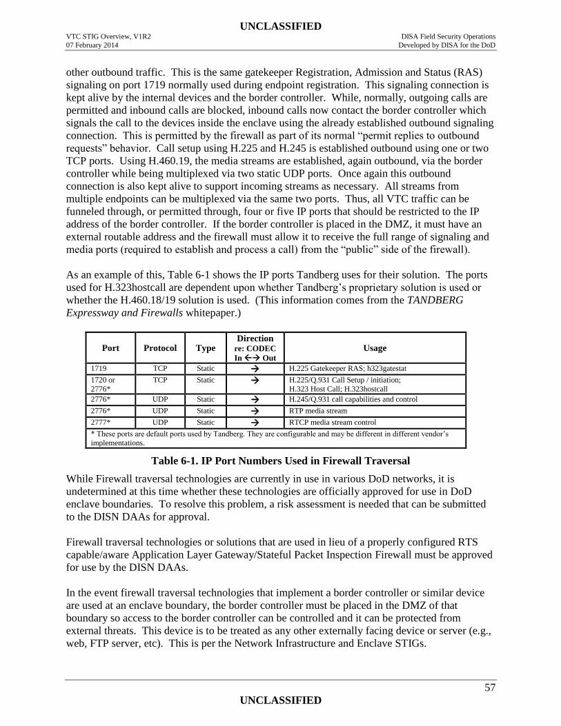
UNCLASSIFIED VTC STIG Overview, V1R2 DISA Field Security Operations
07 February 2014 Developed by DISA for the DoD
57
UNCLASSIFIED
other outbound traffic. This is the same gatekeeper Registration, Admission and Status (RAS)
signaling on port 1719 normally used during endpoint registration. This signaling connection is
kept alive by the internal devices and the border controller. While, normally, outgoing calls are
permitted and inbound calls are blocked, inbound calls now contact the border controller which
signals the call to the devices inside the enclave using the already established outbound signaling
connection. This is permitted by the firewall as part of its normal “permit replies to outbound
requests” behavior. Call setup using H.225 and H.245 is established outbound using one or two
TCP ports. Using H.460.19, the media streams are established, again outbound, via the border
controller while being multiplexed via two static UDP ports. Once again this outbound
connection is also kept alive to support incoming streams as necessary. All streams from
multiple endpoints can be multiplexed via the same two ports. Thus, all VTC traffic can be
funneled through, or permitted through, four or five IP ports that should be restricted to the IP
address of the border controller. If the border controller is placed in the DMZ, it must have an
external routable address and the firewall must allow it to receive the full range of signaling and
media ports (required to establish and process a call) from the “public” side of the firewall).
As an example of this, Table 6-1 shows the IP ports Tandberg uses for their solution. The ports
used for H.323hostcall are dependent upon whether Tandberg’s proprietary solution is used or
whether the H.460.18/19 solution is used. (This information comes from the TANDBERG
Expressway and Firewalls whitepaper.)
Port Protocol Type Direction
re: CODEC
In Out Usage
1719 TCP Static H.225 Gatekeeper RAS; h323gatestat
1720 or
2776*
TCP Static H.225/Q.931 Call Setup / initiation;
H.323 Host Call; H.323hostcall
2776* UDP Static H.245/Q.931 call capabilities and control
2776* UDP Static RTP media stream
2777* UDP Static RTCP media stream control
* These ports are default ports used by Tandberg. They are configurable and may be different in different vendor’s
implementations.
Table 6-1. IP Port Numbers Used in Firewall Traversal
While Firewall traversal technologies are currently in use in various DoD networks, it is
undetermined at this time whether these technologies are officially approved for use in DoD
enclave boundaries. To resolve this problem, a risk assessment is needed that can be submitted
to the DISN DAAs for approval.
Firewall traversal technologies or solutions that are used in lieu of a properly configured RTS
capable/aware Application Layer Gateway/Stateful Packet Inspection Firewall must be approved
for use by the DISN DAAs.
In the event firewall traversal technologies that implement a border controller or similar device
are used at an enclave boundary, the border controller must be placed in the DMZ of that
boundary so access to the border controller can be controlled and it can be protected from
external threats. This device is to be treated as any other externally facing device or server (e.g.,
web, FTP server, etc). This is per the Network Infrastructure and Enclave STIGs.
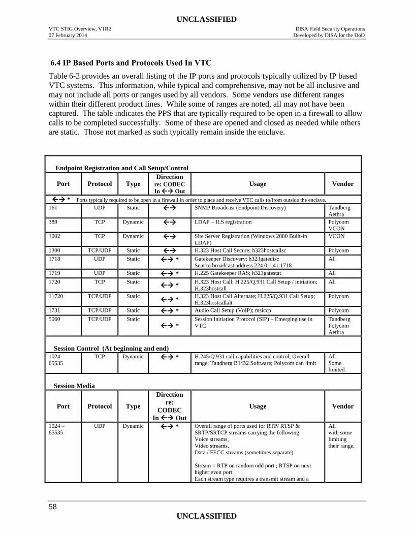
UNCLASSIFIED VTC STIG Overview, V1R2 DISA Field Security Operations
07 February 2014 Developed by DISA for the DoD
58
UNCLASSIFIED
6.4 IP Based Ports and Protocols Used In VTC
Table 6-2 provides an overall listing of the IP ports and protocols typically utilized by IP based
VTC systems. This information, while typical and comprehensive, may not be all inclusive and
may not include all ports or ranges used by all vendors. Some vendors use different ranges
within their different product lines. While some of ranges are noted, all may not have been
captured. The table indicates the PPS that are typically required to be open in a firewall to allow
calls to be completed successfully. Some of these are opened and closed as needed while others
are static. Those not marked as such typically remain inside the enclave.
Endpoint Registration and Call Setup/Control
Port Protocol Type Direction
re: CODEC
In Out Usage Vendor
* Ports typically required to be open in a firewall in order to place and receive VTC calls to/from outside the enclave.
161 UDP Static SNMP Broadcast (Endpoint Discovery) Tandberg
Aethra
389 TCP Dynamic LDAP – ILS registration Polycom
VCON
1002 TCP Dynamic Site Server Registration (Windows 2000 Built-in
LDAP)
VCON
1300 TCP/UDP Static H.323 Host Call Secure; h323hostcallsc Polycom
1718 UDP Static
* Gatekeeper Discovery; h323gatedisc
Sent to broadcast address 224.0.1.41:1718
All
1719 UDP Static * H.225 Gatekeeper RAS; h323gatestat All
1720 TCP Static *
H.323 Host Call; H.225/Q.931 Call Setup / initiation;
H.323hostcall
All
11720 TCP/UDP Static *
H.323 Host Call Alternate; H.225/Q.931 Call Setup;
H.323hostcallalt
Polycom
1731 TCP/UDP Static * Audio Call Setup (VoIP); msiccp Polycom
5060 TCP/UDP Static
* Session Initiation Protocol (SIP) – Emerging use in
VTC
Tandberg
Polycom
Aethra
Session Control (At beginning and end)
1024 –
65535
TCP Dynamic * H.245/Q.931 call capabilities and control; Overall
range; Tandberg B1/B2 Software; Polycom can limit
All
Some
limited.
Session Media
Port Protocol Type
Direction
re:
CODEC
In Out
Usage Vendor
1024 –
65535
UDP Dynamic * Overall range of ports used for RTP/ RTSP &
SRTP/SRTCP streams carrying the following:
Voice streams,
Video streams.
Data / FECC streams (sometimes separate)
Stream = RTP on random odd port ; RTSP on next
higher even port
Each stream type requires a transmit stream and a
All
with some
limiting
their range.
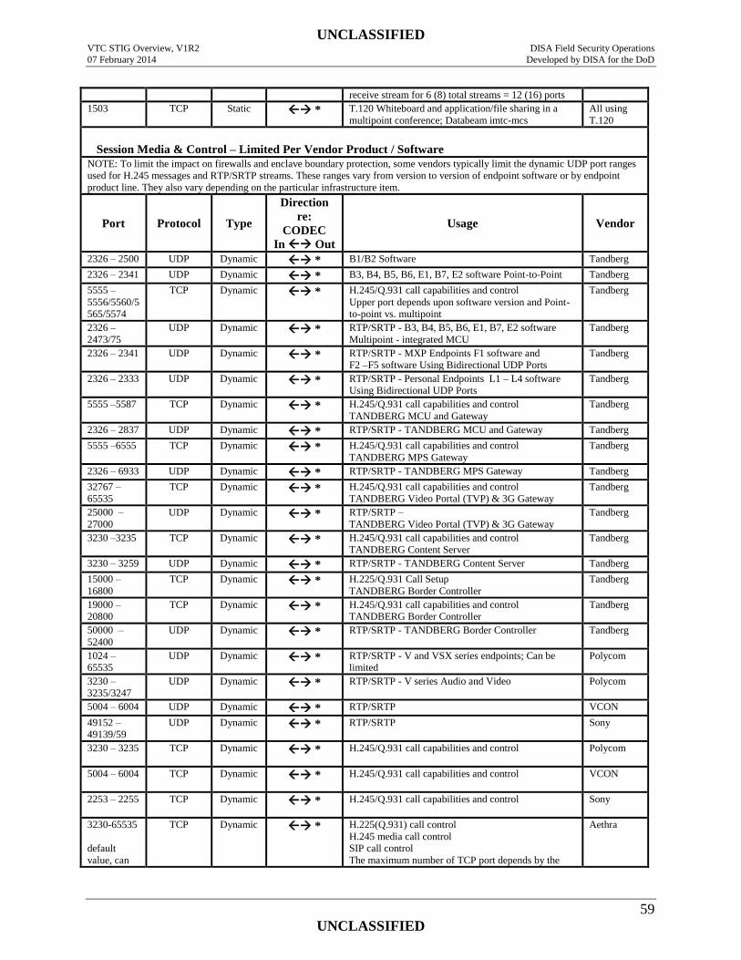
UNCLASSIFIED VTC STIG Overview, V1R2 DISA Field Security Operations
07 February 2014 Developed by DISA for the DoD
59
UNCLASSIFIED
receive stream for 6 (8) total streams = 12 (16) ports
1503 TCP Static * T.120 Whiteboard and application/file sharing in a
multipoint conference; Databeam imtc-mcs
All using
T.120
Session Media & Control – Limited Per Vendor Product / Software
NOTE: To limit the impact on firewalls and enclave boundary protection, some vendors typically limit the dynamic UDP port ranges
used for H.245 messages and RTP/SRTP streams. These ranges vary from version to version of endpoint software or by endpoint
product line. They also vary depending on the particular infrastructure item.
Port Protocol Type
Direction
re:
CODEC
In Out
Usage Vendor
2326 – 2500 UDP Dynamic * B1/B2 Software Tandberg
2326 – 2341 UDP Dynamic * B3, B4, B5, B6, E1, B7, E2 software Point-to-Point Tandberg
5555 –
5556/5560/5
565/5574
TCP Dynamic * H.245/Q.931 call capabilities and control
Upper port depends upon software version and Point-
to-point vs. multipoint
Tandberg
2326 –
2473/75
UDP Dynamic * RTP/SRTP - B3, B4, B5, B6, E1, B7, E2 software
Multipoint - integrated MCU
Tandberg
2326 – 2341 UDP Dynamic * RTP/SRTP - MXP Endpoints F1 software and
F2 –F5 software Using Bidirectional UDP Ports
Tandberg
2326 – 2333 UDP Dynamic * RTP/SRTP - Personal Endpoints L1 – L4 software
Using Bidirectional UDP Ports
Tandberg
5555 –5587 TCP Dynamic * H.245/Q.931 call capabilities and control
TANDBERG MCU and Gateway
Tandberg
2326 – 2837 UDP Dynamic * RTP/SRTP - TANDBERG MCU and Gateway Tandberg
5555 –6555 TCP Dynamic * H.245/Q.931 call capabilities and control
TANDBERG MPS Gateway
Tandberg
2326 – 6933 UDP Dynamic * RTP/SRTP - TANDBERG MPS Gateway Tandberg
32767 –
65535
TCP Dynamic * H.245/Q.931 call capabilities and control
TANDBERG Video Portal (TVP) & 3G Gateway
Tandberg
25000 –
27000
UDP Dynamic * RTP/SRTP –
TANDBERG Video Portal (TVP) & 3G Gateway
Tandberg
3230 –3235 TCP Dynamic * H.245/Q.931 call capabilities and control
TANDBERG Content Server
Tandberg
3230 – 3259 UDP Dynamic * RTP/SRTP - TANDBERG Content Server Tandberg
15000 –
16800
TCP Dynamic * H.225/Q.931 Call Setup
TANDBERG Border Controller
Tandberg
19000 –
20800
TCP Dynamic * H.245/Q.931 call capabilities and control
TANDBERG Border Controller
Tandberg
50000 –
52400
UDP Dynamic * RTP/SRTP - TANDBERG Border Controller Tandberg
1024 –
65535
UDP Dynamic * RTP/SRTP - V and VSX series endpoints; Can be
limited
Polycom
3230 –
3235/3247
UDP Dynamic * RTP/SRTP - V series Audio and Video Polycom
5004 – 6004 UDP Dynamic * RTP/SRTP VCON
49152 –
49139/59
UDP Dynamic * RTP/SRTP Sony
3230 – 3235 TCP Dynamic * H.245/Q.931 call capabilities and control
Polycom
5004 – 6004 TCP Dynamic * H.245/Q.931 call capabilities and control
VCON
2253 – 2255 TCP Dynamic * H.245/Q.931 call capabilities and control
Sony
3230-65535
default
value, can
TCP Dynamic * H.225(Q.931) call control
H.245 media call control
SIP call control
The maximum number of TCP port depends by the
Aethra
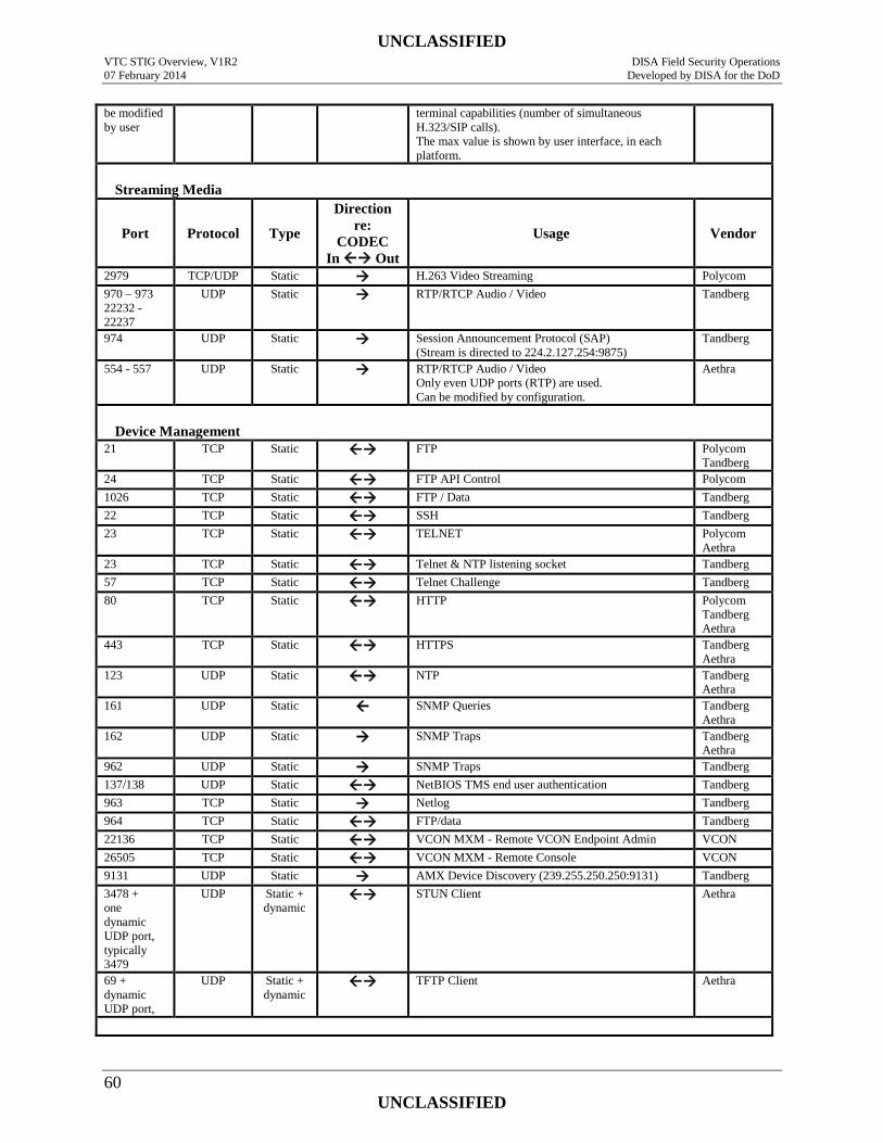
UNCLASSIFIED VTC STIG Overview, V1R2 DISA Field Security Operations
07 February 2014 Developed by DISA for the DoD
60
UNCLASSIFIED
be modified
by user
terminal capabilities (number of simultaneous
H.323/SIP calls).
The max value is shown by user interface, in each
platform.
Streaming Media
Port Protocol Type
Direction
re:
CODEC
In Out
Usage Vendor
2979 TCP/UDP Static H.263 Video Streaming Polycom
970 – 973
22232 -
22237
UDP Static RTP/RTCP Audio / Video Tandberg
974 UDP Static Session Announcement Protocol (SAP)
(Stream is directed to 224.2.127.254:9875)
Tandberg
554 - 557 UDP Static RTP/RTCP Audio / Video
Only even UDP ports (RTP) are used.
Can be modified by configuration.
Aethra
Device Management
21 TCP Static FTP Polycom
Tandberg
24 TCP Static FTP API Control Polycom
1026 TCP Static FTP / Data Tandberg
22 TCP Static SSH Tandberg
23 TCP Static TELNET Polycom
Aethra
23 TCP Static Telnet & NTP listening socket Tandberg
57 TCP Static Telnet Challenge Tandberg
80 TCP Static HTTP Polycom
Tandberg
Aethra
443 TCP Static HTTPS Tandberg
Aethra
123 UDP Static NTP Tandberg
Aethra
161 UDP Static SNMP Queries Tandberg
Aethra
162 UDP Static SNMP Traps Tandberg
Aethra
962 UDP Static SNMP Traps Tandberg 137/138 UDP Static NetBIOS TMS end user authentication Tandberg
963 TCP Static Netlog Tandberg 964 TCP Static FTP/data Tandberg 22136 TCP Static VCON MXM - Remote VCON Endpoint Admin VCON
26505 TCP Static VCON MXM - Remote Console VCON
9131 UDP Static AMX Device Discovery (239.255.250.250:9131) Tandberg
3478 +
one
dynamic
UDP port,
typically
3479
UDP Static +
dynamic STUN Client Aethra
69 +
dynamic
UDP port,
UDP Static +
dynamic TFTP Client Aethra
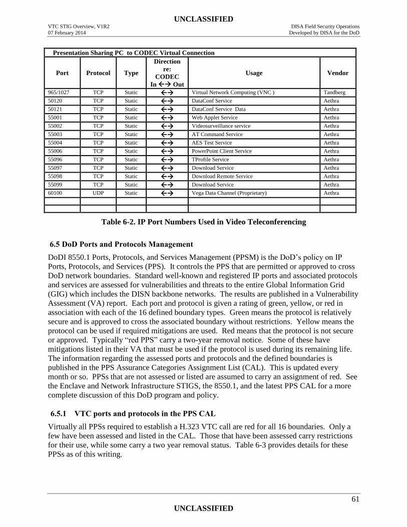
UNCLASSIFIED VTC STIG Overview, V1R2 DISA Field Security Operations
07 February 2014 Developed by DISA for the DoD
61
UNCLASSIFIED
Presentation Sharing PC to CODEC Virtual Connection
Port Protocol Type
Direction
re:
CODEC
In Out
Usage Vendor
965/1027 TCP Static Virtual Network Computing (VNC ) Tandberg 50120 TCP Static DataConf Service Aethra
50121 TCP Static DataConf Service Data Aethra 55001 TCP Static Web Applet Service Aethra 55002 TCP Static Videosurveillance service Aethra 55003 TCP Static AT Command Service Aethra 55004 TCP Static AES Test Service Aethra 55006 TCP Static PowerPoint Client Service Aethra 55096 TCP Static TProfile Service Aethra 55097 TCP Static Download Service Aethra 55098 TCP Static Download Remote Service Aethra 55099 TCP Static Download Service Aethra 60100 UDP Static Vega Data Channel (Proprietary) Aethra
Table 6-2. IP Port Numbers Used in Video Teleconferencing
6.5 DoD Ports and Protocols Management
DoDI 8550.1 Ports, Protocols, and Services Management (PPSM) is the DoD’s policy on IP
Ports, Protocols, and Services (PPS). It controls the PPS that are permitted or approved to cross
DoD network boundaries. Standard well-known and registered IP ports and associated protocols
and services are assessed for vulnerabilities and threats to the entire Global Information Grid
(GIG) which includes the DISN backbone networks. The results are published in a Vulnerability
Assessment (VA) report. Each port and protocol is given a rating of green, yellow, or red in
association with each of the 16 defined boundary types. Green means the protocol is relatively
secure and is approved to cross the associated boundary without restrictions. Yellow means the
protocol can be used if required mitigations are used. Red means that the protocol is not secure
or approved. Typically “red PPS” carry a two-year removal notice. Some of these have
mitigations listed in their VA that must be used if the protocol is used during its remaining life.
The information regarding the assessed ports and protocols and the defined boundaries is
published in the PPS Assurance Categories Assignment List (CAL). This is updated every
month or so. PPSs that are not assessed or listed are assumed to carry an assignment of red. See
the Enclave and Network Infrastructure STIGS, the 8550.1, and the latest PPS CAL for a more
complete discussion of this DoD program and policy.
6.5.1 VTC ports and protocols in the PPS CAL
Virtually all PPSs required to establish a H.323 VTC call are red for all 16 boundaries. Only a
few have been assessed and listed in the CAL. Those that have been assessed carry restrictions
for their use, while some carry a two year removal status. Table 6-3 provides details for these
PPSs as of this writing.
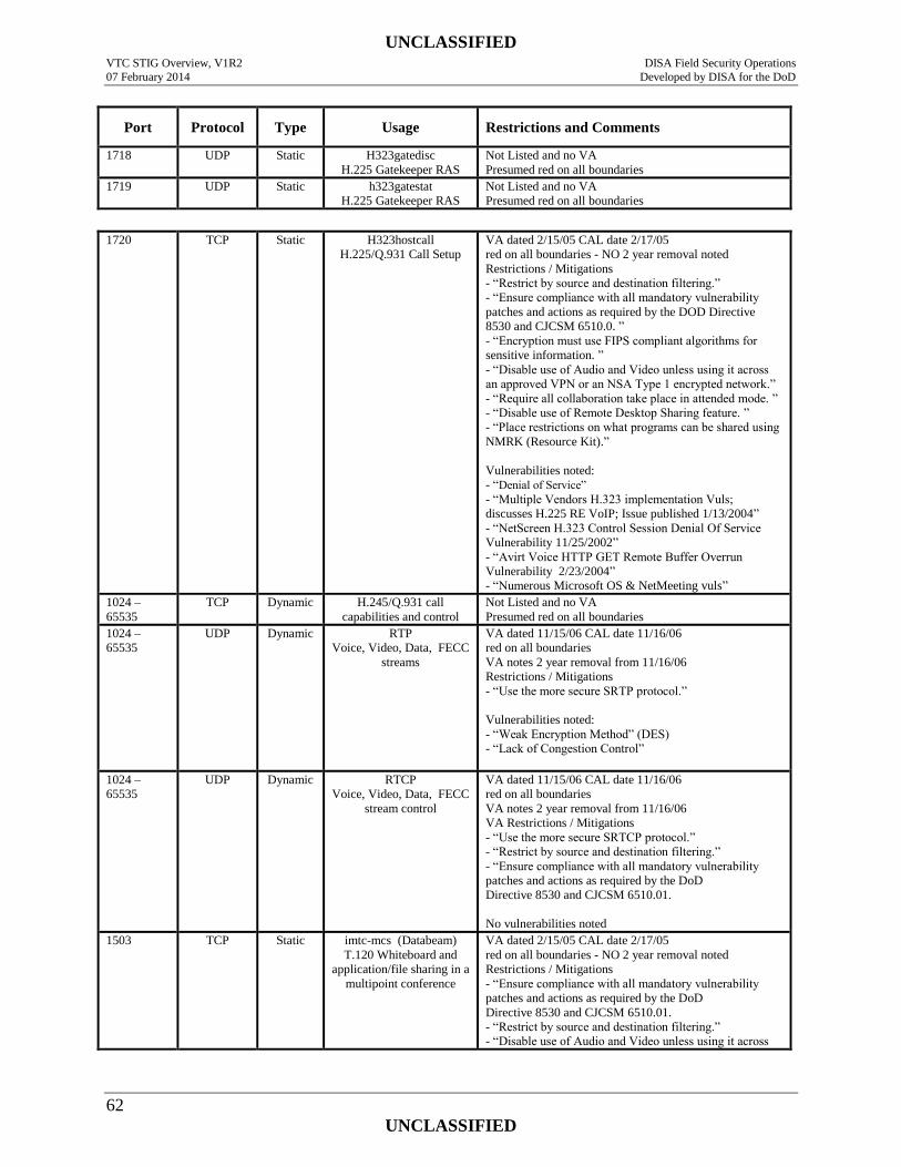
UNCLASSIFIED VTC STIG Overview, V1R2 DISA Field Security Operations
07 February 2014 Developed by DISA for the DoD
62
UNCLASSIFIED
Port Protocol Type Usage Restrictions and Comments
1718 UDP Static H323gatedisc
H.225 Gatekeeper RAS
Not Listed and no VA
Presumed red on all boundaries
1719 UDP Static h323gatestat
H.225 Gatekeeper RAS
Not Listed and no VA
Presumed red on all boundaries
1720 TCP Static H323hostcall
H.225/Q.931 Call Setup
VA dated 2/15/05 CAL date 2/17/05
red on all boundaries - NO 2 year removal noted
Restrictions / Mitigations
- “Restrict by source and destination filtering.”
- “Ensure compliance with all mandatory vulnerability
patches and actions as required by the DOD Directive
8530 and CJCSM 6510.0. ”
- “Encryption must use FIPS compliant algorithms for
sensitive information. ”
- “Disable use of Audio and Video unless using it across
an approved VPN or an NSA Type 1 encrypted network.”
- “Require all collaboration take place in attended mode. ”
- “Disable use of Remote Desktop Sharing feature. ”
- “Place restrictions on what programs can be shared using
NMRK (Resource Kit).”
Vulnerabilities noted:
- “Denial of Service”
- “Multiple Vendors H.323 implementation Vuls;
discusses H.225 RE VoIP; Issue published 1/13/2004”
- “NetScreen H.323 Control Session Denial Of Service
Vulnerability 11/25/2002”
- “Avirt Voice HTTP GET Remote Buffer Overrun
Vulnerability 2/23/2004”
- “Numerous Microsoft OS & NetMeeting vuls”
1024 –
65535
TCP Dynamic H.245/Q.931 call
capabilities and control
Not Listed and no VA
Presumed red on all boundaries
1024 –
65535
UDP Dynamic RTP
Voice, Video, Data, FECC
streams
VA dated 11/15/06 CAL date 11/16/06
red on all boundaries
VA notes 2 year removal from 11/16/06
Restrictions / Mitigations
- “Use the more secure SRTP protocol.”
Vulnerabilities noted:
- “Weak Encryption Method” (DES)
- “Lack of Congestion Control”
1024 –
65535
UDP Dynamic RTCP
Voice, Video, Data, FECC
stream control
VA dated 11/15/06 CAL date 11/16/06
red on all boundaries
VA notes 2 year removal from 11/16/06
VA Restrictions / Mitigations
- “Use the more secure SRTCP protocol.”
- “Restrict by source and destination filtering.”
- “Ensure compliance with all mandatory vulnerability
patches and actions as required by the DoD
Directive 8530 and CJCSM 6510.01.
No vulnerabilities noted
1503 TCP Static imtc-mcs (Databeam)
T.120 Whiteboard and
application/file sharing in a
multipoint conference
VA dated 2/15/05 CAL date 2/17/05
red on all boundaries - NO 2 year removal noted
Restrictions / Mitigations
- “Ensure compliance with all mandatory vulnerability
patches and actions as required by the DoD
Directive 8530 and CJCSM 6510.01.
- “Restrict by source and destination filtering.”
- “Disable use of Audio and Video unless using it across
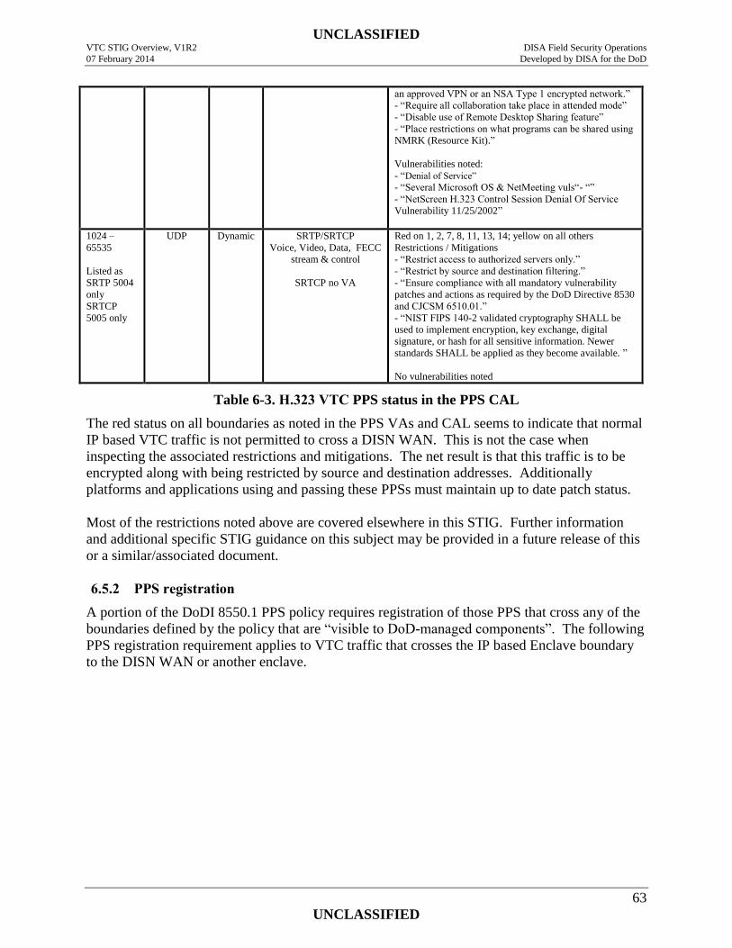
UNCLASSIFIED VTC STIG Overview, V1R2 DISA Field Security Operations
07 February 2014 Developed by DISA for the DoD
63
UNCLASSIFIED
an approved VPN or an NSA Type 1 encrypted network.”
- “Require all collaboration take place in attended mode”
- “Disable use of Remote Desktop Sharing feature”
- “Place restrictions on what programs can be shared using
NMRK (Resource Kit).”
Vulnerabilities noted:
- “Denial of Service”
- “Several Microsoft OS & NetMeeting vuls“- “”
- “NetScreen H.323 Control Session Denial Of Service
Vulnerability 11/25/2002”
1024 –
65535
Listed as
SRTP 5004
only
SRTCP
5005 only
UDP Dynamic SRTP/SRTCP
Voice, Video, Data, FECC
stream & control
SRTCP no VA
Red on 1, 2, 7, 8, 11, 13, 14; yellow on all others
Restrictions / Mitigations
- “Restrict access to authorized servers only.”
- “Restrict by source and destination filtering.”
- “Ensure compliance with all mandatory vulnerability
patches and actions as required by the DoD Directive 8530
and CJCSM 6510.01.”
- “NIST FIPS 140-2 validated cryptography SHALL be
used to implement encryption, key exchange, digital
signature, or hash for all sensitive information. Newer
standards SHALL be applied as they become available. ”
No vulnerabilities noted
Table 6-3. H.323 VTC PPS status in the PPS CAL
The red status on all boundaries as noted in the PPS VAs and CAL seems to indicate that normal
IP based VTC traffic is not permitted to cross a DISN WAN. This is not the case when
inspecting the associated restrictions and mitigations. The net result is that this traffic is to be
encrypted along with being restricted by source and destination addresses. Additionally
platforms and applications using and passing these PPSs must maintain up to date patch status.
Most of the restrictions noted above are covered elsewhere in this STIG. Further information
and additional specific STIG guidance on this subject may be provided in a future release of this
or a similar/associated document.
6.5.2 PPS registration
A portion of the DoDI 8550.1 PPS policy requires registration of those PPS that cross any of the
boundaries defined by the policy that are “visible to DoD-managed components”. The following
PPS registration requirement applies to VTC traffic that crosses the IP based Enclave boundary
to the DISN WAN or another enclave.
UNCLASSIFIED VTC STIG Overview, V1R2 DISA Field Security Operations
07 February 2014 Developed by DISA for the DoD
64
UNCLASSIFIED
7. SECURE/NON-SECURE VTC SECURITY
This section will encompass requirements (not covered elsewhere) for the use and
implementation of secure, as well as secure/nonsecure VTC endpoints and HUBs that process
classified information i.e., support classified conferences. At this time, this section only provides
a description of this type of VTC system.
7.1 Classified / Un-Classified Conferencing Systems
The previous discussions can relate to both un-classified and classified conferences. All
classified conferences require NSA type-1 cryptography and key management. The
implementation of this cryptography depends upon the transmission method and the network that
is carrying the transmitted information. VTUs that support both classified and un-classified
conferences are sometimes referred to as secure/non-secure devices or systems.
Dial-up VTC systems can support both classified and un-classified conferences if properly
equipped. Dial-up conferences can be established either in an unclassified mode or in a
classified mode. A special A/B switch is used to switch the crypto device into the EIA-530 serial
connection between the CODEC and a required external IMUX. An additional piece of
equipment is required which is called a dial isolator. This is a device that breaks the EIA-366
dialing information connection between the CODEC and the IMUX when the IMUX signals the
dial isolator that the call is connected. Both the A/B switch and dial isolator are TEMPEST
certified devices since they are required to provide proper high isolation between the clear-text
information in the CODEC and the cipher-text information passing through the IMUX and out to
the ISDN lines.
IP based VTC systems are typically connected directly to an IP network that determines the
classification level, up to which, a classified VTC can be held. In other words the VTU inherits
the classification level of the network to which it is attached. VTUs can be fitted with a special
A/B switch to permit the VTU to be used on a classified or un-classified network. An A/B
switch can also be used to permit a VTU to be used on different classified networks having
different classification levels. Such an A/B switch must be rigorously tested and approved for
Multi Level Security (MLS) applications because it touches two networks of differing
classifications and must prevent the passing of traffic between these networks. Such an A/B
switch performs an IA function as its primary purpose (i.e., maintaining the separation of the
networks having different classifications). It is therefore subject to NIAP Common Criteria
Validation in accordance with DoDI 8500.2 IA control DCAS-1 and NSTISSP No. 11.
An additional concern when switching a VTU from a classified network to an unclassified
network is the possible retention of classified information within the CODEC. This information
could be contained in the address book or in log files, or possibly in some other memory
location. To eliminate this problem, the CODEC must be flushed of this information. Rebooting
the CODEC by cycling the power off, and then on with an appropriate time delay, will clear any
information stored in volatile memory. This will not, however, clear information in non-volatile
memory where the address book and logs would be stored. To overcome this problem special
secure / non-secure switching systems have been developed that delete files stored in non-
UNCLASSIFIED VTC STIG Overview, V1R2 DISA Field Security Operations
07 February 2014 Developed by DISA for the DoD
65
UNCLASSIFIED
volatile memory that might contain classified information before cycling the power on the
CODEC and subsequently connecting it to the unclassified network.
Figure 7-1 illustrates a secure/non-secure VTU along with its optional network connections. The
optional connections shown are mutually exclusive since a VTU must not be simultaneously
connected to a classified and unclassified network. This means that the VTU cannot be
connected to a classified IP based network while also being connected to the dial-up network
which is unclassified.
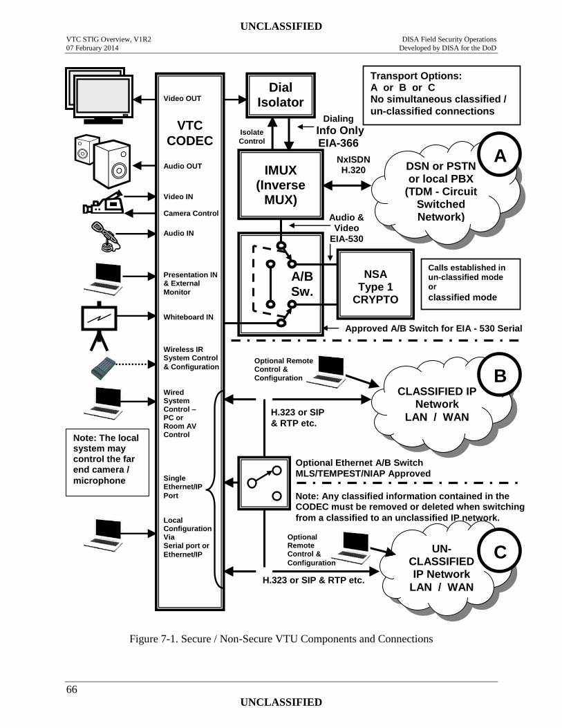
UNCLASSIFIED VTC STIG Overview, V1R2 DISA Field Security Operations
07 February 2014 Developed by DISA for the DoD
66
UNCLASSIFIED
Figure 7-1. Secure / Non-Secure VTU Components and Connections
H.323 or SIP
& RTP etc.
Isolate
Control
Note: The local system may control the far end camera /
microphone
Dialing
Info Only EIA-366
Dial Isolator
Audio & Video
EIA-530
NxISDN H.320
DSN or PSTN or local PBX
(TDM - Circuit Switched Network)
CLASSIFIED IP Network
LAN / WAN
A/B Sw.
NSA Type 1
CRYPTO
IMUX (Inverse
MUX)
VTC
CODEC
Video OUT
Audio OUT
Presentation IN & External
Monitor
Audio IN
Video IN
Whiteboard IN
Camera Control
Wired System Control – PC or Room AV Control
Wireless IR System Control
& Configuration
H.323 or SIP & RTP etc.
UN- CLASSIFIED IP Network
LAN / WAN
B
A
B
C
Transport Options: A or B or C No simultaneous classified /
un-classified connections
Calls established in un-classified mode or
classified mode
Local Configuration Via Serial port or
Ethernet/IP
Optional Ethernet A/B Switch
MLS/TEMPEST/NIAP Approved Single Ethernet/IP
Port
Optional Remote Control &
Configuration
Approved A/B Switch for EIA - 530 Serial
Note: Any classified information contained in the CODEC must be removed or deleted when switching
from a classified to an unclassified IP network.
Optional Remote Control &
Configuration
UNCLASSIFIED VTC STIG Overview, V1R2 DISA Field Security Operations
07 February 2014 Developed by DISA for the DoD
67
UNCLASSIFIED
Multipoint secure/classified conferences require that each MCU port be equipped with an
appropriate crypto device (dependent upon connection type) which decrypts the VTC stream
before the MCU can join them together. This applies to IP based, as well as dial-up connections.
An MCU must be dedicated to each classification level and/or classified network supported by
the facility. This is because the MCU is a VTC network infrastructure device with a number of
connections to the supported network (much like a LAN switch or router). If a single MCU were
to support two or more networks having different classification levels, an A/B switch would be
required for each port/connection on the MCU just as is the case with a single endpoint/CODEC.
All A/B switches would have to be switched in unison to maintain separation of the two
networks and not cause a connection to be made between them through the MCU. This is not
practical and is dangerous to the maintenance of network separation. A mitigation for this would
be to have all MCU and network switch ports on patch panels. The MCU, unclassified, and
classified networks appear on separate patch panels. The MCU would be patched to either the
unclassified OR classified network. An SOP would need to be implemented whereby all patch
cords are removed prior to any being connected to the other network.
UNCLASSIFIED VTC STIG Overview, V1R2 DISA Field Security Operations
07 February 2014 Developed by DISA for the DoD
68
UNCLASSIFIED
8. VTC HUB/MCU SECURITY
This section will encompass requirements (not covered elsewhere) for Media Conferencing
Units, Gateways, scheduling systems, etc., as used in enterprise level VTC applications/systems,
as well as service provider hubs, such as DVS-II.
8.1 Access Control for Multipoint Conferences
Access control must be exercised over participants joining multipoint conferences. Attendees
and/or endpoints must be pre-authorized or pre-registered. In this way, conference/meeting
organizers can control who has access to sensitive or classified information based upon validated
clearance and need-to-know. Unrestricted access or the use of a meeting password that is reused
and/or well-known can lead to a security incident where information is improperly disclosed to
unauthorized individuals not having appropriate clearance or need-to-know.
In a previous topic, the access control required was discussed for multipoint conferences hosted
by a VTC endpoint with an integrated MCU. Typically access control for such meetings is
handled manually by the operator of the hosting VTU calling the participants and then joining
them to the conference. This is positive access control with the conference host controlling who
has access to the session and being responsible, therefore, for the conferees need-to-know or
authorization to receive conference information. Additionally, if call-in access is supported and
approved, a one time use meeting password is required.
Multipoint conferences hosted on a MCU appliance or network element must also perform
access control over who can join a meeting . This includes employing proper practices for
distributing conference information, as well as for assigning access codes. If access control is
not exercised, anyone who knows any phone number or IP address on the MCU can “dial-in”
any time and access whatever meeting is being hosted on the MCU at the given time. This
cannot be permitted.
MCU Access control can be performed in various ways that may differ from vendor’s product to
vendor’s product. Typically, MCU access is controlled by an H.323 gatekeeper, which uses
H.225 gatekeeper RAS messages between itself and its endpoints. A combination of access
control lists on the MCU and gatekeeper can also limit access. A full description of this process
is beyond the scope of this release of this STIG but a brief description follows along with an
issue. Further information can be found in several books and tutorials that are available in both
print and on the web.
H.323 gatekeepers provide access control for VTC network infrastructure devices, such as
MCUs and gateways to VTC endpoints. Using H.225 an endpoint can discover a gatekeeper and
register with it. The endpoint is identified by the gatekeeper by a “gatekeeper password” which
is essentially the endpoint ID. The gatekeeper provides address translation and bandwidth
management. Once registered with the gatekeeper an endpoint must ask permission of the
gatekeeper to make a call. If the available VTC bandwidth is used or limited, the gatekeeper can
reject the request or negotiate a lower bandwidth. This acts as part of the access control
mechanism for the MCU and works in combination with a scheduling application. The rest of
the MCU access control equation is pre registration of the endpoint IDs when scheduling a
UNCLASSIFIED VTC STIG Overview, V1R2 DISA Field Security Operations
07 February 2014 Developed by DISA for the DoD
69
UNCLASSIFIED
conference. Pre registration of endpoint IDs for specific conferences is required because there
are typically no meeting passwords and the phone numbers or IP addresses of the MCU ports
don’t change between sessions. Additionally (and here’s the issue mentioned above) people are
not authenticated only endpoints are. The endpoint ID is critical in this access control process.
The endpoint ID is entered (pre-configured) in the system for a specific scheduled conference.
The system only permits the endpoint to access the MCU during the scheduled time of the
conference.
This discussion also applies to ad hoc conferences and “standing” conferences. A standing
conference is one where MCU facilities are dedicated to a conference that is operational all of
the time or one that is regularly scheduled to be operational for certain time periods. The
implementation of a standing conference permits conferees to join the conference at will or as
needed to discuss a current topic or mission. Standing conferences are implemented for many
reasons. Standing conferences are more vulnerable to compromise than one time scheduled
events. Extra care must be exercised regarding access control to these conferences.
8.2 Conference Scheduling Systems
Conference scheduling systems are used to ensure MCU and network facilities are available
when a conference is going to occur. This is done by a reservation process whereby the facilities
are reserved for the conference. A scheduling system can also be used to send invitations,
typically via email, to conferees containing meeting access information. Access to the
scheduling system is handled in one of three ways. The first is by an administrator or helpdesk
representative. A meeting organizer contacts the help desk and the helpdesk representative
interacts with the scheduling system. The second and third methods of accessing the scheduling
system are user based. The meeting organizer (user) accesses the scheduling system via a web
page and browser or via another collaboration application, such as MS Outlook or IBM
Sametime (and/or others).
8.2.1 Scheduling system access control
Access control to the conference scheduling system must be exercised and limited to authorized
individuals. This is accomplished in different ways depending upon the access method.
Scheduling systems accessed by users or administrators via a web interface must comply with all
of the requirements for a web server and/or applications server to include DoD access control
(e.g., DoD PKI) and auditing requirements for such devices/systems. Scheduling systems
accessed via a collaboration tool must minimally utilize the access control required for accessing
the collaboration application. Since an authorized user of a collaboration tool may or may not
have the right to schedule VTC conferences, the scheduling application should receive user
credentials from the collaboration application to determine authorization or the right must be
controlled by the collaboration application. Scheduling systems accessed by administrators
using other methods must also employ access control and auditing meeting DoD requirements.
UNCLASSIFIED VTC STIG Overview, V1R2 DISA Field Security Operations
07 February 2014 Developed by DISA for the DoD
70
UNCLASSIFIED
APPENDIX A. ACRONYMS
AAA Authentication, Authorization, and Accountability
ALG Application Layer Gateway
ALT Alternate Logon Token
API Application Programmer’s Interface
APL Approved Product List
AS-SIP Assured Services SIP
AV Audio Visual
ATO Approval to Operate
BRI Basic Rate Interface
CAC Common Access Card
CAL Categories Assignment List
C2 Command and Control
CDR Call Detail Records
CODEC Coder-Decoder
CMVP Cryptographic Module Validation Program
CTO Command Tasking Order
DAA Designated Approving Authority
DISN Defense Information Systems Network
DoD Department of Defense
DoDD DoD Directive
DoDI DoD Instruction
DSAWG DISN Security Accreditation Working Group
DSCP Differential Service Code Point
DSN Defense Switched Network
EI End Instrument
EMS Element Management System
ENUM TElephone NUmber Mapping
FECC Far end camera control
FIPS Federal Information Processing Standard
FTP File Transfer Protocol
GIG Global Information Grid
HTTP Hypertext Transfer Protocol
HTTPS Hypertext Transfer Protocol Secure
I&A Identification And Authentication
IA Information Assurance
UNCLASSIFIED VTC STIG Overview, V1R2 DISA Field Security Operations
07 February 2014 Developed by DISA for the DoD
71
UNCLASSIFIED
IAO Information Assurance Officer
IAVM Information Assurance Vulnerability Management
ILS Internet Locater service
ISP Information Support Plan
IST Inter-Switch Trunk
IP Internet Protocol
IMUX Inverse Multiplexer
INFOCON Information Operations Condition
ISDN Integrated Services Digital Network
ITU International Telecommunications Union
JTF-GNO Joint Task Force -Global Network Operations
LDAP Lightweight Directory Access Protocol
MAC Mission Assurance Category
MCU Multipoint Control Unit
MLPP Multi-Level Precedence and Priority
MXP Tandberg product line designation and technology name
MPS Tandberg Media Processing System
NAT Network Address Translation
NIC Network Interface Card
NIST National Institute of Standards
NMS Network Management System
NSTISSP National Security Telecommunications and Information Systems Security Policy
NTP Network Time Protocol
QOS Quality of Service
PC Personal Computer
PCMCIA Personal Computer Memory Card International Association
PIN Personal Identification Number
PKI Public Key Infrastructure
PPS Ports, Protocols, and Services
PPSM Ports, Protocols, and Services Management
PRI Primary Rate Interface
PSTN Public Switched Telephone Network
PTT Push-to-Talk
RAS (H.323 Gatekeeper) Registration, Admission, and Status
RTS Real Time Service(s)
RTP Real Time Protocol
RTCP Real Time Control Protocol
SAP Session Announcement Protocol
UNCLASSIFIED VTC STIG Overview, V1R2 DISA Field Security Operations
07 February 2014 Developed by DISA for the DoD
72
UNCLASSIFIED
SRTP Secure RTP
SSH Secure Shell
SRTCP Secure RTCP
SIP Session Initiation Protocol
SOP Standard Operating Procedure
SNMP Simple Network Management Protocol
T-ISP Tailored Information Support Plan
TCP Transmission Control Protocol.
TDM Time Division Multiplexing
TMS Tandberg Management Suite
TVP Tandberg Video Portal
TTL Time-To-Live
UDP User Datagram Protocol
URL Universal or Uniform Resource Locator
URI Uniform Resource Identifier
VA Vulnerability Assessment
VC Video Conferencing
VNC Virtual Network Computing
VSX Polycom product line designation
VTC Video Tele-Conferencing
VTU Video Teleconferencing Unit
VoIP Voice over IP or Video over IP
V/VoIP Voice / Video over IP
WLAN Wireless Local Area Network