Embed Size (px)
Citation preview
VIDEO SURVEILLANCE SYSTEM 16726-1
SECTION 16726 - VIDEO SURVEILLANCE SYSTEM PART 1 - GENERAL
1.1 RELATED DOCUMENTS
A. The General Provisions of the Contract, including the General Conditions, Supplementary Conditions and Special Conditions, along with the General Requirements, apply to the work specified in this Section.
1.2 DESCRIPTION
A. Work covered under this section consists of furnishing and installing a complete commercial UL-listed, camera system as indicated on the drawings and specified herein. In event of conflict, specifications take precedence over drawings. System shall include all required head end equipment, monitors, cameras, and interconnecting wiring.
1.3 SUBMITTALS
A. Product Data: For each type of product indicated, including dimensions and data on features, performance, electrical characteristics, ratings, and finishes. Submittals must include photographs of all items.
1. Data which describes more than one type of item shall be clearly marked to indicate which type the Contractor intends to provide. Submit one original for each item and clear, legible, first-generation photocopies for the remainder of the specified copies. Incomplete or illegible photocopies will not be accepted. Partial submittals will not be accepted.
B. Shop Drawings: Provide drawings that clearly and completely indicate the functions of the equipment, components and cameras connected thereto. Drawings shall indicate all physical location of all equipment and cameras. Indicate the interconnections required for proper operation of the system. Show wire counts. Drawings shall be the same size as the full size contract documents.
1. Functional Block Diagram: Show single-line interconnections between components for signal transmission. Show cable types and sizes.
2. Dimensioned plan and elevations of equipment racks, control panels, and consoles. Show access and workspace requirements.
3. Wiring Diagrams: Power, signal, and control wiring, and grounding.
C. Equipment List: Include every piece of equipment by model number, manufacturer, serial number, location, and date of original installation.
D. Minimum Installer Qualifications:
1. Successfully completed classes covering basic camera installation and basic camera troubleshooting.
2. Possess March Networks Integrator Certification.
VIDEO SURVEILLANCE SYSTEM AT (School name and number)
DCSB PROJECT NO. X-XXXXX
VIDEO SURVEILLANCE SYSTEM 16726-2
3. Have a service department located within a 75 mile radius of the project location. Documentation verifying above requirements must be submitted as part of the bid package. Failure to include certification in bid package will result in disqualification of bid.
1.4 QUALITY ASSURANCE
A. Electrical Components, Devices, and Accessories: Listed and labeled as defined in NFPA 70, Article 100, by a testing agency acceptable to authorities having jurisdiction, and marked for intended use.
B. Comply with NECA 1.
C. Comply with NFPA 70.
D. Electronic data exchange between video surveillance system and an access control system shall comply with SIA TVAC.
E. Reference Standards: Materials and workmanship shall conform to the Standards of the current National Electrical Code, the latest edition of the Florida Building Code, Americans with Disabilities Act (Public Law 101-336), and any applicable state and local codes. All equipment shall be U.L. listed.
1.5 PROJECT CONDITIONS
A. Environmental Conditions: Capable of withstanding the following environmental conditions without mechanical or electrical damage or degradation of operating capability:
1. Interior, Controlled Environment: System components installed in air-conditioned interior environments shall be rated for continuous operation in ambient temperatures of 36 to 122 deg F dry bulb and 20 to 90 percent relative humidity, non-condensing. NEMA 250, Type 1 enclosures.
2. Interior, Uncontrolled Environment: System components installed in non-air-conditioned interior environments shall be rated for continuous operation in ambient temperatures of 0 to 122 deg F dry bulb and 20 to 90 percent relative humidity, non-condensing. NEMA 250, Type 3R enclosures.
3. Exterior Environment: System components installed in locations exposed to weather shall be rated for continuous operation in ambient temperatures of minus 30 to plus 122 deg F dry bulb and 20 to 90 percent relative humidity, condensing. Rate for continuous operation when exposed to rain as specified in NEMA 250, winds up to 120 mph. NEMA 250, Type 3R enclosures.
4. Hazardous Environment: System components located in areas where fire or explosion hazards may exist because of flammable gases or vapors, flammable liquids, combustible dust, or ignitable fibers shall be rated, listed, and installed according to NFPA 70.
5. Corrosive Environment: System components subjected to corrosive fumes, vapors, and wind-driven salt spray in coastal zones. NEMA 250, Type 4X enclosures.
VIDEO SURVEILLANCE SYSTEM AT (School name and number)
DCSB PROJECT NO. X-XXXXX
VIDEO SURVEILLANCE SYSTEM 16726-3
6. Security Environment: Camera housing for use in high-risk areas where surveillance equipment may be subject to physical violence.
1.6 APPROVED MANUFACTURERS
A. All equipment shall be new and in current production, UL listed, and come with the latest versions of software and firmware. Scope of work shall include cost for and installation of all software and firmware upgrades during warranty period.
B. All equipment shall be manufactured as specified within and as approved by DCPS Instructional Equipment Foreman.
1.7 SUBSTITUTIONS
A. Requirements: To maintain compatibility with existing DCPS camera equipment, no substitutions will be accepted unless approved in writing by DCPS Instructional Equipment Foreman.
1.8 WARRANTY
A. Manufacturer's standard form in which manufacturer agrees to repair or replace components of cameras and/or equipment related to camera operation that fails in materials or workmanship within specified warranty period. Response time may not exceed 24 hours.
1. Warranty Period: One year from date of Substantial Completion.
B. The contractor’s warranty shall provide for inspection of all trouble issues within 12 months of system acceptance. When contacted by DCPS, the contractor shall visit the site and determine cause of trouble at no cost to Owner. The contractor shall correct any problems related to product failure or system installation. If the trouble was the result of an event beyond the control of the contractor (vandalism, act of nature, etc.), the contractor shall notify DCPS of cause of trouble.
C. One month prior to expiration of warranty, the contractor shall coordinate and schedule a final warranty inspection. Attendees shall include the DCPS Instructional Equipment Foreman and the project engineer/designer of record. The School’s Resource Officer (SRO) and the school’s Principal shall also be notified so that they may attend the inspection if they wish to. Upon completion of installation, contractor shall clean all camera domes with a product approved for plastic materials. Provide an application of water-repellent solution to the outside of the domes. The product must be approved for use with plastic materials. Refer to manufacturer instructions for proper application method.
PART 2 – PRODUCTS
2.1 SYSTEM REQUIREMENTS
A. Video signal format shall comply with the NTSC standard composite video, interlaced. Composite video signal termination shall be 75 ohms.
VIDEO SURVEILLANCE SYSTEM AT (School name and number)
DCSB PROJECT NO. X-XXXXX
VIDEO SURVEILLANCE SYSTEM 16726-4
All installed cables must be within the parameters recommended by the equipment manufacturer.
B. Surge Protection: Protect components from voltage surges entering through power, communication, signal, control, or sensing leads. Include surge protection for external wiring of each conductor entry connection to components.
1. Minimum Protection for Power Connections 120 V and More: Auxiliary panel suppressors complying with requirements in Division 16 Section "Transient-Voltage Suppression."
2. Minimum Protection for Communication, Signal, Control, and Low-Voltage Power Connections: Comply with manufacturer's recommendation for type of line being protected.
2.2 EQUIPMENT AND COMPONENTS
A. Equipment and components shall conform to applicable requirements of NFPA 70. Units of the same type of the equipment shall be the product of single manufacturer, unless otherwise specified. Equipment shall be installed in accordance with manufacturer specifications.
B. Hybrid Network Video Recorder: March Networks #8732R with 16 analog inputs and 32 IP inputs.
1. Provide software, plus four hard drives. Each hard drive shall be 4 TB, for a total of 16 TB of storage.
C. Cameras: Cameras manufacturers and models are specified on the contract drawings. Refer to the project electrical drawings. Provide cameras as indicated. Substitutions will not be accepted.
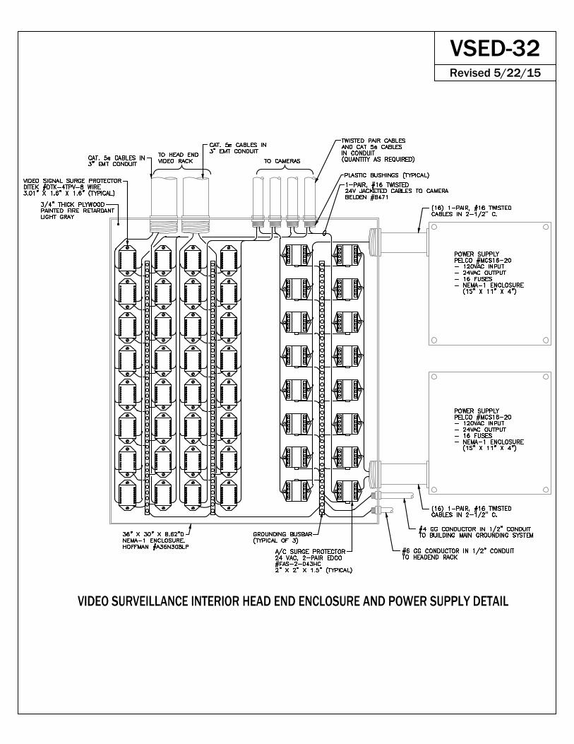
D. Head End Cabinet. One, heavy-gauge steel, welded, enclosed 19” rack with front plexiglass and back steel access doors both with perimeter venting. This black, stand-alone cabinet shall be a minimum of 84 x 24” x 32” with 10/32 tapped rails. Each cabinet shall have a minimum of 16 power positions and 2 exhaust fans. A maximum of two NVR’s and associated equipment are permissible per 7’ cabinet. Approved manufacturer is Great Lake Cabinets, model #840E-2432DCS-CCTV.
Original and all duplicate keys to cabinets shall be provided only to the Instructional Equipment Foreman, Maintenance Station #3.
With approval from Instructional Equipment Foreman, Maintenance Station #3, installation in limited space may use Middle Atlantic #SR-46-28 with wire mesh vented front door #VFD-46.
UPS must be provided, model as specified below. UPS shall solely support the NVR. Each NVR requires its own UPS.
E. Head End Cabinet Monitor: Single, 15”-19”, rack mounted or provide pedestal stand with rack mount shelf kit.
F. Passive UTP Transceiver: PELCO #TW3016P
G. Fiber Rack Mount Chassis: PELCO #RK5000PS-3U
VIDEO SURVEILLANCE SYSTEM AT (School name and number)
DCSB PROJECT NO. X-XXXXX
VIDEO SURVEILLANCE SYSTEM 16726-5
H. Fiber Receiver: PELCO #FR85011AMSTR
I. Fiber Transceiver: PELCO #FS85011MST
J. Active UTP Receiver: PELCO #TW3001AR
K. Surge Protectors:
1. DITEK #DTK-4TPV (video signal)
2. EDCO #FAS-2-043HC (24Volt A/C)
L. UPS: 1500 VA manufactured by APC, model #SMT1500RM2U. Provide required rack mount hardware.
M. Power Supply: PELCO #MCS16-20. Alternate models are acceptable when specified on drawings or as approved during submittal process.
N. Monitoring Location Equipment (optional): (Required provisions to be determined on a case-by-case basis): 1. Multiplexer: Speco #RMX16CD 2. Video Distribution Amplifier: PELCO #DA104DT 3. Switcher: PELCO #VS5104 (with #R300 rack mount kit for head
end location only) 4. Viewing Station Monitor: (1) 32” LCD monitor (desk or wall
mounted as specified on drawing). Submit product data for review and approval. Suggested manufacturers are NEC and Panasonic.
PART 3 – INSTALLATION
3.1 GENERAL REQUIEMENTS
A. Provide and install the system in accordance with the plans and specifications, all applicable codes and the manufacturer's recommendations. All wiring shall be installed in strict compliance with all the provisions of NEC. Any deviations from the plans and/or specifications must be approved in writing by DCPS Instructional Equipment Foreman.
B. Prior to start of work, the contractor shall coordinate and schedule an onsite walk-through to verify exact locations of viewing stations and cameras (including mountings). Attendees shall include the DCPS School Police Chief or appointed designee, the school’s Principal or appointed designee, the project engineer/designer of record, and the DCPS Instructional Equipment Foreman.
C. The contractor shall provide the school’s Principal with weekly project schedule updates. Until the system is fully operation and has been inspected and approved, the contractor shall field all questions from Principal. If an issue arises between the contractor and the Principal, the contractor shall immediately contact DCPS Instructional Equipment Foreman to address the issue.
D. Cameras: Shall be furnished and mounted as recommended by the manufacturer. Conflicts between manufacturer recommendations and the
VIDEO SURVEILLANCE SYSTEM AT (School name and number)
DCSB PROJECT NO. X-XXXXX
VIDEO SURVEILLANCE SYSTEM 16726-6
requirements of this specification shall be brought to the attention of DCPS Instructional Equipment Foreman for resolution.
E. All conduits shall be installed in accordance with Specification Section 16130.
F. No exposed cables shall be permitted. Pull all conductors splice free. Make all conductor connections under screw terminals. Provide insulated barrier type nylon terminal strips at junction points and as indicated to insure a neat and orderly termination of all cabling. Use of wire nuts, crimped connectors, or twisting of conductors is prohibited. Head end equipment and peripheral equipment shall be dressed out in a professional manner with all wires running in the vertical or horizontal plane, cut to exact length, making all turns at 90 degree angles, and tightly bundled and wire wrapped.
G. The contractor shall clean all dirt and debris from the inside and the outside of equipment after completion of the installation. The contractor shall clean up all areas of the site where work was performed or trailers, dumpsters, etc. were located. Upon completion of the cleanup, the contractor shall obtain a written sign-off from the Principal stating they are satisfied with the condition of the site.
3.2 INSTALLATION
A. WIRING
1. Cabling:
a) For interior cameras, utilize Cat. 5e cables (not to exceed 295 feet)
b) For exterior cameras, utilize single-mode fiber optic cables
c) For jumpers, utilize RG-59 coaxial cables
2. Camera power wiring shall be Belden cable #8471. Color-coding will be white=positive and black=negative. Current draws for power shall be measured and provided to DCPS Instructional Equipment Foreman with the completed system layout. All power to cameras shall be within allowable current drops for the camera to function properly with camera voltage no lower than 2 volts above the minimum operating voltage.
3. Wiring Method: Install cables in conduit. No exposed cable shall be permitted. Conceal conduits in accessible ceilings, walls, and floors where possible. The contractor shall install all wire, conduit, and equipment in accordance with Division 16 of Specifications and current National Electrical Code (NEC), specifically Article 110 Section 12 which shall be interpreted and enforced by the DCPS Code Enforcement and DCPS Instructional Equipment Foreman serving as authorities having jurisdiction (AHJ).
4. Wiring within Enclosures: Cables shall be neatly managed and labeled. Tie wraps shall be not accepted.

VIDEO SURVEILLANCE SYSTEM AT (School name and number)
DCSB PROJECT NO. X-XXXXX
VIDEO SURVEILLANCE SYSTEM 16726-7
5. Splices, Taps, and Terminations: For power and control wiring, use numbered terminal strips in junction, pull, and outlet boxes; terminal cabinets; and equipment enclosures. Tighten electrical connectors and terminals according to manufacturer's published torque-tightening values.
6. Grounding: Provide independent-signal circuit grounding recommended in writing by manufacturer.
7. Wiring terminations are allowed only at the camera, interior boxes and video rack locations with all wiring terminations clearly identifying cameras specifically by location and camera number. Video signal and data wiring shall pass through interior boxes locations via 110 connections. 66 punch-down blocks will not be used.
8. The head end equipment (video racks) shall be installed in a new dedicated cabinet, as specified on the drawings, and have dedicated power.
9. All terminated wiring must be installed in a neat and professional manner utilizing wire management procedures. Cable wiring in cabinets shall be routed in such a manner to allow for future rewiring in the cabinet. All head end wiring at the rack shall be secured with Velcro straps (tie wraps are not permitted).
10. All conduits and camera enclosures must be completely sealed. Provide silicone beads for inside camera enclosures to eliminate build-up of moisture.
11. An electronic labeling machine shall be used to identify all wiring. Any terminated wire must be identified at all points of connection or termination and at all pull boxes.
B. EQUIPMENT
1. Cameras shall be installed per the DCPS Instructional Equipment Foreman’s specific instruction. Any deviation of location or redesign of the installation must be requested in e-mail to the DCPS Instructional Equipment Foreman for written authorization. Engineer/designer of record shall be copied on all correspondence.
2. Camera system head end equipment shall be housed in fully enclosed cabinet with fans.
3. Provide patch panels, amplifiers, mixers, signal distributors, interface modules, switchers, contactors, and all other needed equipment for proper connection and operation of cameras, monitors, and NVR’s.
4. Power for head end cabinet shall be fed from emergency power panel.
VIDEO SURVEILLANCE SYSTEM AT (School name and number)
DCSB PROJECT NO. X-XXXXX
VIDEO SURVEILLANCE SYSTEM 16726-8
5. Install cameras with 84 inch minimum clear space below cameras and their mountings. Change type of mounting to achieve required clearance.
6. No camera shall be mounted higher than 12 feet above grade of finished floor without the written approval of DCPS Instructional Equipment Foreman.
7. Camera views shall not have any “dead space” such as ceilings in the recording frame.
8. Cameras shall be set for day/night operation (dusk to dawn).
9. Cameras located on poles, canopies, or in buildings separate from that housing the headend rack shall use fiber connectivity. Locate power supply in Nema-3R, lockable enclosure, mounted at 48” above grade. Power supply shall have surge suppression. Pole and equipment shall be grounded.
10. All pole and wall mounted installations shall be able to hold a minimum of 80 lbs. Use toggle bolts, etc. as necessary.
11. All cameras shall have an accessible video connection point for camera adjustments and service to be made without moving the camera from its installed position to connect to the access point.
12. All interior cameras shall be installed with clear domes and exterior cameras shall be installed with smoke domes unless specifically indicated otherwise by the DCPS Instructional Equipment Foreman.
13. Camera housings may not be supported by ceiling tiles. Camera housing shall be supported to the building structure via threaded rods or aircraft cables.
14. The contractor shall turn over all manufacturer software CD’s only to the DCPS Instructional Equipment Foreman.
15. Upon completion of installation, contractor shall clean all camera domes with a product approved for plastic materials. Provide an application of water-repellent solution to the outside of the domes. The product must be approved for use with plastic materials. Refer to the product’s manufacturer instructions for proper application method.
C. POWER AND SURGE PROTECTION
1. All suppression equipment shall be identified on as built designs submitted to DCPS and installed as per manufacturers’ requirements.
2. UTP video signal wiring shall have DITEK DTK-4TPV installed prior to signal entering the active transceiver at the head end. The surge suppression shall be installed in a dedicated metal enclosure located near the rack. The enclosure shall be identified as “VIDEO SURGE SUPPRESSION”.
3. All suppression shall be properly grounded with adherence to NEC code requirements.
VIDEO SURVEILLANCE SYSTEM AT (School name and number)
DCSB PROJECT NO. X-XXXXX
VIDEO SURVEILLANCE SYSTEM 16726-9
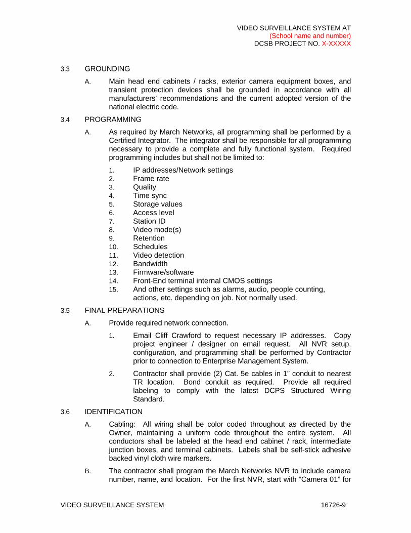
3.3 GROUNDING
A. Main head end cabinets / racks, exterior camera equipment boxes, and transient protection devices shall be grounded in accordance with all manufacturers’ recommendations and the current adopted version of the national electric code.
3.4 PROGRAMMING
A. As required by March Networks, all programming shall be performed by a Certified Integrator. The integrator shall be responsible for all programming necessary to provide a complete and fully functional system. Required programming includes but shall not be limited to:
1. IP addresses/Network settings 2. Frame rate 3. Quality 4. Time sync 5. Storage values 6. Access level 7. Station ID 8. Video mode(s) 9. Retention 10. Schedules 11. Video detection 12. Bandwidth 13. Firmware/software 14. Front-End terminal internal CMOS settings 15. And other settings such as alarms, audio, people counting,
actions, etc. depending on job. Not normally used.
3.5 FINAL PREPARATIONS
A. Provide required network connection.
1. Email Cliff Crawford to request necessary IP addresses. Copy project engineer / designer on email request. All NVR setup, configuration, and programming shall be performed by Contractor prior to connection to Enterprise Management System.
2. Contractor shall provide (2) Cat. 5e cables in 1” conduit to nearest TR location. Bond conduit as required. Provide all required labeling to comply with the latest DCPS Structured Wiring Standard.
3.6 IDENTIFICATION
A. Cabling: All wiring shall be color coded throughout as directed by the Owner, maintaining a uniform code throughout the entire system. All conductors shall be labeled at the head end cabinet / rack, intermediate junction boxes, and terminal cabinets. Labels shall be self-stick adhesive backed vinyl cloth wire markers.
B. The contractor shall program the March Networks NVR to include camera number, name, and location. For the first NVR, start with “Camera 01” for
VIDEO SURVEILLANCE SYSTEM AT (School name and number)
DCSB PROJECT NO. X-XXXXX
VIDEO SURVEILLANCE SYSTEM 16726-10
the first camera. For additional NVR’s, start with “17/01”, etc. Identification shall include brief geographical description of camera location.
3.7 QUALITY ASSURANCE
A. The electrical contractor shall install all conduit, enclosures, back boxes, and wiring required for the installation of the Camera System. However, all cameras and equipment shall be installed and tested by a trained representative of the camera system contractor, see “Testing“ below.
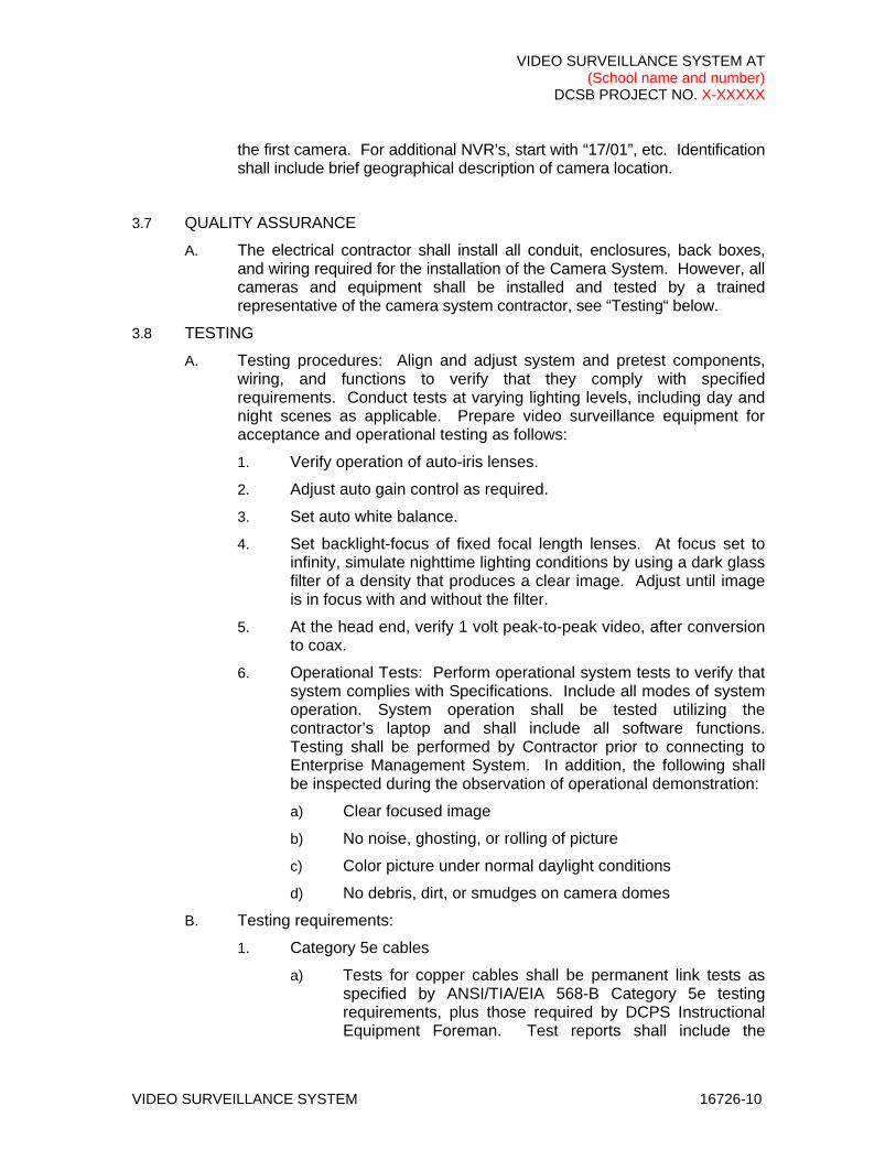
3.8 TESTING
A. Testing procedures: Align and adjust system and pretest components, wiring, and functions to verify that they comply with specified requirements. Conduct tests at varying lighting levels, including day and night scenes as applicable. Prepare video surveillance equipment for acceptance and operational testing as follows:
1. Verify operation of auto-iris lenses.
2. Adjust auto gain control as required.
3. Set auto white balance.
4. Set backlight-focus of fixed focal length lenses. At focus set to infinity, simulate nighttime lighting conditions by using a dark glass filter of a density that produces a clear image. Adjust until image is in focus with and without the filter.
5. At the head end, verify 1 volt peak-to-peak video, after conversion to coax.
6. Operational Tests: Perform operational system tests to verify that system complies with Specifications. Include all modes of system operation. System operation shall be tested utilizing the contractor’s laptop and shall include all software functions. Testing shall be performed by Contractor prior to connecting to Enterprise Management System. In addition, the following shall be inspected during the observation of operational demonstration:
a) Clear focused image
b) No noise, ghosting, or rolling of picture
c) Color picture under normal daylight conditions
d) No debris, dirt, or smudges on camera domes
B. Testing requirements:
1. Category 5e cables
a) Tests for copper cables shall be permanent link tests as specified by ANSI/TIA/EIA 568-B Category 5e testing requirements, plus those required by DCPS Instructional Equipment Foreman. Test reports shall include the

VIDEO SURVEILLANCE SYSTEM AT (School name and number)
DCSB PROJECT NO. X-XXXXX
VIDEO SURVEILLANCE SYSTEM 16726-11
following information and meet the following specifications as a minimum:
(1) Frequency sweep (1 MHZ – 100 MHZ), Cable Length, Attenuation, Near End Cross Talk (Next), Wire Map (also called Line Mapping), Power Sum NEXT, ELFEXT, PSELFEXT, Return Loss, as well as ACR pp, Power Sum ACR, and 100BaseTX certification.
b) Fiber optic cables
(1) Tier 1 and Tier 2 testing is required of all fiber strands. Setup of all fiber optic OTDR testing shall require both a 100m launch and 100m receive cable to be used. Settings for Range, Resolution, and Pulse Width are to be approved in writing by DCPS Instructional Equipment Foreman prior to testing. These settings will be based on information provided by the contractor from true tape or jacket marking distances.
Use TIA-526-14A reference method B to zero out the launch and receive cables. All fiber strands, connectors, and bulkheads shall be thoroughly cleaned with an approved product. Test in both directions at both 850 and 1300nm. OTDR A-B points shall be set based on the following description:
The A point shall be set just prior to the first mated pair of the fiber under test. The B point shall be set just prior to the last mated pair of the fiber under test.
Final A-B locations for connector and total loss shall be determined by DCPS Instructional Equipment Foreman NOT the contractor. No mated pair connector loss shall exceed 0.5 db. Total loss shall not exceed 0.75 db per fiber, unless approved in writing by DCPS Instructional Equipment Foreman. This will only possibly be approved due to long multimode fiber distances (i.e. >500 ft).
(2) Each OTDR and Power Meter & Light source test file shall be identified by the origin and destination of the test, bulkhead position, color of the fiber and the wavelength(s) tested. Each fiber trace shall be evaluated for length, continuity, insertion loss, connector loss, and smoothness of the trace. Any trace showing excessive connector or total loss must be corrected and retested. All header information shall be completed including but not
VIDEO SURVEILLANCE SYSTEM AT (School name and number)
DCSB PROJECT NO. X-XXXXX
VIDEO SURVEILLANCE SYSTEM 16726-12
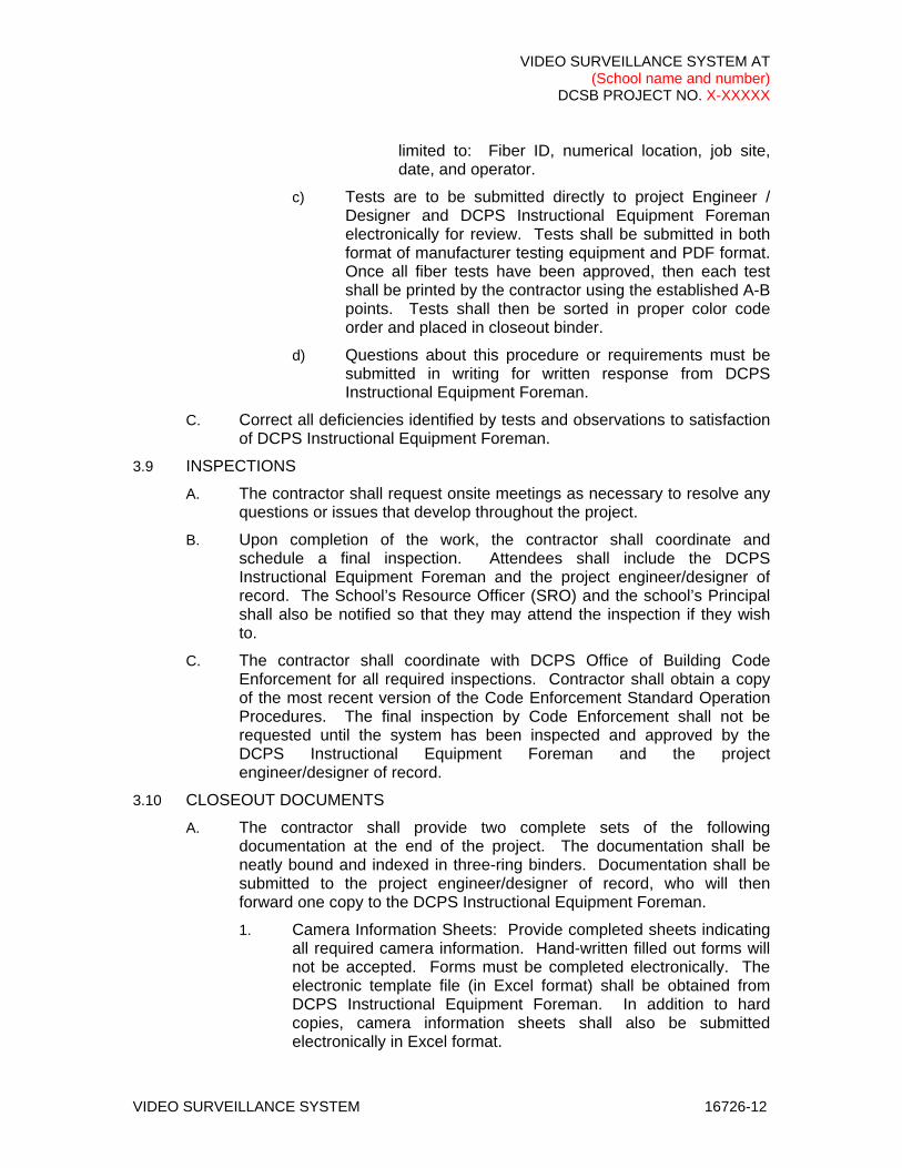
limited to: Fiber ID, numerical location, job site, date, and operator.
c) Tests are to be submitted directly to project Engineer / Designer and DCPS Instructional Equipment Foreman electronically for review. Tests shall be submitted in both format of manufacturer testing equipment and PDF format. Once all fiber tests have been approved, then each test shall be printed by the contractor using the established A-B points. Tests shall then be sorted in proper color code order and placed in closeout binder.
d) Questions about this procedure or requirements must be submitted in writing for written response from DCPS Instructional Equipment Foreman.
C. Correct all deficiencies identified by tests and observations to satisfaction of DCPS Instructional Equipment Foreman.
3.9 INSPECTIONS
A. The contractor shall request onsite meetings as necessary to resolve any questions or issues that develop throughout the project.
B. Upon completion of the work, the contractor shall coordinate and schedule a final inspection. Attendees shall include the DCPS Instructional Equipment Foreman and the project engineer/designer of record. The School’s Resource Officer (SRO) and the school’s Principal shall also be notified so that they may attend the inspection if they wish to.
C. The contractor shall coordinate with DCPS Office of Building Code Enforcement for all required inspections. Contractor shall obtain a copy of the most recent version of the Code Enforcement Standard Operation Procedures. The final inspection by Code Enforcement shall not be requested until the system has been inspected and approved by the DCPS Instructional Equipment Foreman and the project engineer/designer of record.
3.10 CLOSEOUT DOCUMENTS
A. The contractor shall provide two complete sets of the following documentation at the end of the project. The documentation shall be neatly bound and indexed in three-ring binders. Documentation shall be submitted to the project engineer/designer of record, who will then forward one copy to the DCPS Instructional Equipment Foreman.
1. Camera Information Sheets: Provide completed sheets indicating all required camera information. Hand-written filled out forms will not be accepted. Forms must be completed electronically. The electronic template file (in Excel format) shall be obtained from DCPS Instructional Equipment Foreman. In addition to hard copies, camera information sheets shall also be submitted electronically in Excel format.
VIDEO SURVEILLANCE SYSTEM AT (School name and number)
DCSB PROJECT NO. X-XXXXX
VIDEO SURVEILLANCE SYSTEM 16726-13
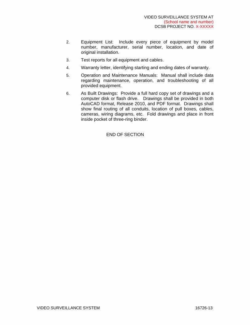
2. Equipment List: Include every piece of equipment by model number, manufacturer, serial number, location, and date of original installation.
3. Test reports for all equipment and cables.
4. Warranty letter, identifying starting and ending dates of warranty.
5. Operation and Maintenance Manuals: Manual shall include data regarding maintenance, operation, and troubleshooting of all provided equipment.
6. As Built Drawings: Provide a full hard copy set of drawings and a computer disk or flash drive. Drawings shall be provided in both AutoCAD format, Release 2010, and PDF format. Drawings shall show final routing of all conduits, location of pull boxes, cables, cameras, wiring diagrams, etc. Fold drawings and place in front inside pocket of three-ring binder.
END OF SECTION

VSED-16Revised 5/22/15
VSED-32Revised 5/22/15
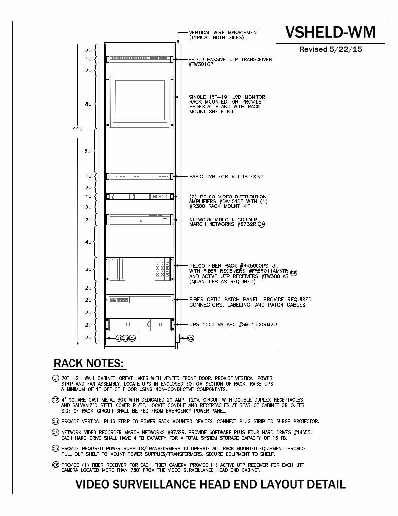
RACK NOTES:
VIDEO SURVEILLANCE HEAD END LAYOUT DETAIL
VSHELD-WMRevised 5/22/15
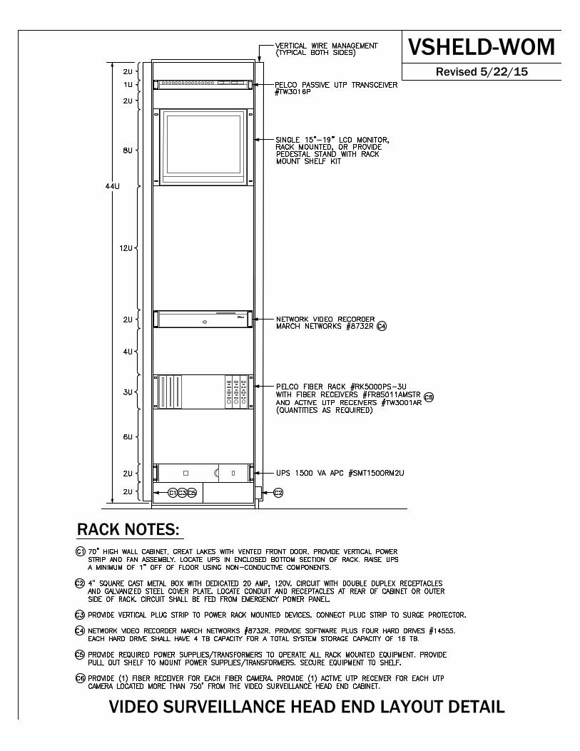
RACK NOTES:
VIDEO SURVEILLANCE HEAD END LAYOUT DETAIL
VSHELD-WOMRevised 5/22/15

VIDEO SURVEILLANCE HEAD END RISER DIAGRAM
RISER NOTES:
VSHERD-WMRevised 5/22/15

VIDEO SURVEILLANCE HEAD END RISER DIAGRAM
RISER NOTES:
VSHERD-WOMRevised 5/22/15


![presentation KLH DBI 2015.05.20.ppt [Kompatibilitätsmodus] klh_dbi_20150520.pdf · KLH ‐STRUCTURE Access ... Wall panels KLH 5s 128mm ... Stadthaus, Murray Grove - Waugh Thistleton](https://img.pdfslide.us/doc/110x75/5aa194cf7f8b9a84398bdc75/presentation-klh-dbi-20150520ppt-kompatibilittsmodus-klhdbi20150520pdfklh.jpg)