Embed Size (px)
Citation preview
UD06175B
Video Intercom Door Station
(V Series)
User Manual
Video Intercom Door Station·User Manual
i
User Manual
© 2017 Hangzhou Hikvision Digital Technology Co., Ltd.
This user manual is intended for users of the models below:
Series Model
Door Station (V Series)
DS-KV8102-IM
DS-KV8202-IM
DS-KV8402-IM
DS-KV8102-IP
DS-KV8102-VP
It includes instructions on how to use the Product. The software embodied in the Product is governed by the user license agreement covering that product.
About this Manual
This Manual is subject to domestic and international copyright protection. Hangzhou Hikvision Digital Technology Co., Ltd. (“Hikvision”) reserves all rights to this manual. This manual cannot be reproduced, changed, translated, or distributed, partially or wholly, by any means, without the prior written permission of Hikvision.
Trademarks
and other Hikvision marks are the property of Hikvision and are registered trademarks or the subject of applications for the same by Hikvision and/or its affiliates. Other trademarks mentioned in this manual are the properties of their respective owners. No right of license is given to use such trademarks without express permission.
Disclaimer
TO THE MAXIMUM EXTENT PERMITTED BY APPLICABLE LAW, HIKVISION MAKES NO WARRANTIES,
EXPRESS OR IMPLIED, INCLUDING WITHOUT LIMITATION THE IMPLIED WARRANTIES OF
MERCHANTABILITY AND FITNESS FOR A PARTICULAR PURPOSE, REGARDING THIS MANUAL. HIKVISION DOES NOT WARRANT, GUARANTEE, OR MAKE ANY REPRESENTATIONS REGARDING THE
USE OF THE MANUAL, OR THE CORRECTNESS, ACCURACY, OR RELIABILITY OF INFORMATION
CONTAINED HEREIN. YOUR USE OF THIS MANUAL AND ANY RELIANCE ON THIS MANUAL SHALL BE
WHOLLY AT YOUR OWN RISK AND RESPONSIBILITY.
TO THE MAXIMUM EXTENT PERMITTED BY APPLICABLE LAW, IN NO EVENT WILL HIKVISION, ITS
DIRECTORS, OFFICERS, EMPLOYEES, OR AGENTS BE LIABLE TO YOU FOR ANY SPECIAL,
CONSEQUENTIAL, INCIDENTAL, OR INDIRECT DAMAGES, INCLUDING, AMONG OTHERS, DAMAGES
Video Intercom Door Station·User Manual
ii
FOR LOSS OF BUSINESS PROFITS, BUSINESS INTERRUPTION, SECURITY BREACHES, OR LOSS OF DATA OR DOCUMENTATION, IN CONNECTION WITH THE USE OF OR RELIANCE ON THIS MANUAL, EVEN IF
HIKVISION HAS BEEN ADVISED OF THE POSSIBILITY OF SUCH DAMAGES.
SOME JURISDICTIONS DO NOT ALLOW THE EXCLUSION OR LIMITATION OF LIABILITY OR CERTAIN
DAMAGES, SO SOME OR ALL OF THE ABOVE EXCLUSIONS OR LIMITATIONS MAY NOT APPLY TO YOU.
Support
Should you have any questions, please do not hesitate to contact your local dealer.
Video Intercom Door Station·User Manual
iii
Regulatory Information
FCC Information
Please take attention that changes or modification not expressly approved by the party responsible for compliance could void the user’s authority to operate the equipment.
FCC compliance: This equipment has been tested and found to comply with the limits for a Class B digital device, pursuant to part 15 of the FCC Rules. These limits are designed to provide reasonable protection against harmful interference in a residential installation. This equipment generates, uses and can radiate radio frequency energy and, if not installed and used in accordance with the instructions, may cause harmful interference to radio communications. However, there is no guarantee that interference will not occur in a particular installation. If this equipment does cause harmful interference to radio or television reception, which can be determined by turning the equipment off and on, the user is encouraged to try to correct the interference by one or more of the following measures:
—Reorient or relocate the receiving antenna.
—Increase the separation between the equipment and receiver.
—Connect the equipment into an outlet on a circuit different from that to which the receiver is connected.
—Consult the dealer or an experienced radio/TV technician for help.
FCC Conditions
This device complies with part 15 of the FCC Rules. Operation is subject to the following two conditions:
1. This device may not cause harmful interference. 2. This device must accept any interference received, including interference that may cause undesired operation.
EU Conformity Statement
This product and - if applicable - the supplied accessories too are marked with "CE" and comply therefore with the applicable harmonized European standards listed under the EMC Directive 2014/30/EU, the RoHS Directive 2011/65/EU.
2012/19/EU (WEEE directive): Products marked with this symbol cannot be disposed of as unsorted municipal waste in the European Union. For proper recycling, return this product to your local supplier upon the purchase of equivalent new equipment, or dispose of it at designated collection points. For more information see: www.recyclethis.info
Video Intercom Door Station·User Manual
iv
2006/66/EC (battery directive): This product contains a battery that cannot be disposed of as unsorted municipal waste in the European Union. See the product documentation for specific battery information. The battery is marked with this symbol, which may include lettering to indicate cadmium (Cd), lead (Pb), or mercury (Hg). For proper recycling, return the battery to your supplier or to a designated collection point. For more information see: www.recyclethis.info
Industry Canada ICES-003 Compliance
This device meets the CAN ICES-3 (B)/NMB-3(B) standards requirements.
Video Intercom Door Station·User Manual
v
Safety Instruction These instructions are intended to ensure that user can use the product correctly to avoid danger or property loss.
The precaution measure is divided into Warnings and Cautions:
Warnings: Neglecting any of the warnings may cause serious injury or death. Cautions: Neglecting any of the cautions may cause injury or equipment damage.
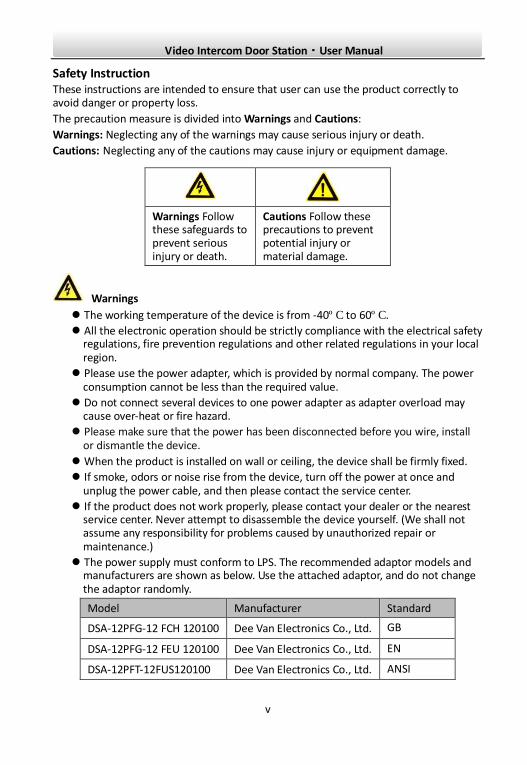
Warnings The working temperature of the device is from -40º C to 60º C.
All the electronic operation should be strictly compliance with the electrical safety regulations, fire prevention regulations and other related regulations in your local region.
Please use the power adapter, which is provided by normal company. The power consumption cannot be less than the required value.
Do not connect several devices to one power adapter as adapter overload may cause over-heat or fire hazard.
Please make sure that the power has been disconnected before you wire, install or dismantle the device.
When the product is installed on wall or ceiling, the device shall be firmly fixed.
If smoke, odors or noise rise from the device, turn off the power at once and unplug the power cable, and then please contact the service center.
If the product does not work properly, please contact your dealer or the nearest service center. Never attempt to disassemble the device yourself. (We shall not assume any responsibility for problems caused by unauthorized repair or maintenance.)
The power supply must conform to LPS. The recommended adaptor models and manufacturers are shown as below. Use the attached adaptor, and do not change the adaptor randomly.
Model Manufacturer Standard
DSA-12PFG-12 FCH 120100 Dee Van Electronics Co., Ltd. GB
DSA-12PFG-12 FEU 120100 Dee Van Electronics Co., Ltd. EN
DSA-12PFT-12FUS120100 Dee Van Electronics Co., Ltd. ANSI
Warnings Follow these safeguards to prevent serious injury or death.
Cautions Follow these precautions to prevent potential injury or material damage.
Video Intercom Door Station·User Manual
vi
Model Manufacturer Standard
DSA-12PFG-12 FUK 120100 Dee Van Electronics Co., Ltd. BSW
DSA-12PFG-12 FAU 120100 Dee Van Electronics Co., Ltd. AS
Cautions Do not drop the device or subject it to physical shock, and do not expose it to high
electromagnetism radiation. Avoid the equipment installation on vibrations surface or places subject to shock (ignorance can cause equipment damage).
Do not place the device in extremely hot (refer to the specification of the device for the detailed operating temperature), cold, dusty or damp locations, and do not expose it to high electromagnetic radiation.
The device cover for indoor use shall be kept from rain and moisture.
Exposing the equipment to direct sun light, low ventilation or heat source such as heater or radiator is forbidden (ignorance can cause fire danger).
Do not aim the device at the sun or extra bright places. A blooming or smear may occur otherwise (which is not a malfunction however), and affecting the endurance of sensor at the same time.
Please use the provided glove when open up the device cover, avoid direct contact with the device cover, because the acidic sweat of the fingers may erode the surface coating of the device cover.
Please use a soft and dry cloth when clean inside and outside surfaces of the device cover, do not use alkaline detergents.
Please keep all wrappers after unpack them for future use. In case of any failure occurred, you need to return the device to the factory with the original wrapper. Transportation without the original wrapper may result in damage on the device and lead to additional costs.
Improper use or replacement of the battery may result in hazard of explosion. Replace with the same or equivalent type only. Dispose of used batteries according to the instructions provided by the battery manufacturer.
Video Intercom Door Station·User Manual
vii
Table of Contents 1 Overview ...................................................................................................... 1
1.1 Introduction ........................................................................................................ 1 1.2 Main Features ..................................................................................................... 1
2 Appearance .................................................................................................. 2
2.1 Appearance of DS-KV8X02-IM .............................................................................. 2 2.2 Appearance of DS-KV8102-XP .............................................................................. 3
3 Typical Application ....................................................................................... 5
3.1 Typical Application of DS-KV8X02-IM .................................................................... 5 3.2 Typical Application of DS-KV8102-XP .................................................................... 6
4 Terminal and Wiring ..................................................................................... 7
4.1 Terminal Description ............................................................................................ 7 4.2 Wiring Description ............................................................................................... 8
4.2.1 Door Lock Wiring........................................................................................... 8 4.2.2 Door Magnetic Wiring ................................................................................... 9 4.2.3 Exit Button Wiring ......................................................................................... 9 4.2.4 Alarm Device Input Wiring ........................................................................... 10 4.2.5 RS-485 Card Reader Wiring .......................................................................... 11 4.2.6 External Elevator Controller Wiring .............................................................. 11
5 Installation ................................................................................................. 12
5.1 Installation of DS-KV8X02-IM ............................................................................. 12 5.1.1 Gang Box for DS-KV8X02-IM ........................................................................ 12 5.1.2 Wall Mounting with Gang Box of DS-KV8X02-IM ........................................... 13
5.2 Installation of DS-KV8102-XP .............................................................................. 14 5.2.1 Installation Plate for DS-KV8102-XP .............................................................. 14 5.2.2 Wall Mounting with Gang Box of DS-KV8102-XP ........................................... 15
6 Before You Start ......................................................................................... 17
7 Remote Operation via Batch Configuration Tool ......................................... 18
7.1 Activating Device Remotely ................................................................................ 18 7.2 Editing Network Parameters............................................................................... 19 7.3 Adding Device ................................................................................................... 20
7.3.1 Adding Online Device .................................................................................. 20 7.3.2 Adding by IP Address ................................................................................... 21 7.3.3 Adding by IP Segment .................................................................................. 22
7.4 Configuring Devices Remotely ............................................................................ 23 7.4.1 System ........................................................................................................ 23 7.4.2 Video Intercom ........................................................................................... 28 7.4.3 Network ...................................................................................................... 32
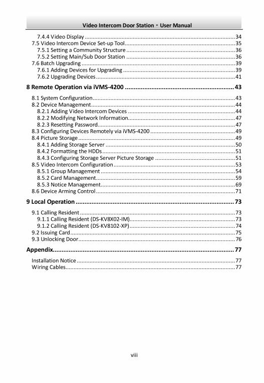
Video Intercom Door Station·User Manual
viii
7.4.4 Video Display .............................................................................................. 34 7.5 Video Intercom Device Set-up Tool ..................................................................... 35
7.5.1 Setting a Community Structure .................................................................... 36 7.5.2 Setting Main/Sub Door Station .................................................................... 36
7.6 Batch Upgrading ................................................................................................ 39 7.6.1 Adding Devices for Upgrading ...................................................................... 39 7.6.2 Upgrading Devices ....................................................................................... 41
8 Remote Operation via iVMS-4200 .............................................................. 43
8.1 System Configuration ......................................................................................... 43 8.2 Device Management .......................................................................................... 44
8.2.1 Adding Video Intercom Devices ................................................................... 44 8.2.2 Modifying Network Information................................................................... 47 8.2.3 Resetting Password...................................................................................... 47
8.3 Configuring Devices Remotely via iVMS-4200 ..................................................... 49 8.4 Picture Storage .................................................................................................. 49
8.4.1 Adding Storage Server ................................................................................. 50 8.4.2 Formatting the HDDs ................................................................................... 51 8.4.3 Configuring Storage Server Picture Storage .................................................. 51
8.5 Video Intercom Configuration ............................................................................ 53 8.5.1 Group Management .................................................................................... 54 8.5.2 Card Management ....................................................................................... 59 8.5.3 Notice Management .................................................................................... 69
8.6 Device Arming Control ....................................................................................... 71
9 Local Operation .......................................................................................... 73
9.1 Calling Resident ................................................................................................. 73 9.1.1 Calling Resident (DS-KV8X02-IM).................................................................. 73 9.1.2 Calling Resident (DS-KV8102-XP) .................................................................. 74
9.2 Issuing Card ....................................................................................................... 75 9.3 Unlocking Door .................................................................................................. 76
Appendix....................................................................................................... 77
Installation Notice ................................................................................................... 77 Wiring Cables .......................................................................................................... 77
Video Intercom Door Station·User Manual
1
1 Overview
1.1 Introduction The door station (V series) can realize functions such as video intercom, access control,
one-card system, zone alarm, and visitor messages to form a complete smart community
video intercom solution.
The door station (V series) is mainly applied in the villa, and can works as door station,
outer door station, and doorphone.
1.2 Main Features Video intercom function
HD video surveillance (Max. resolution 1280×720@25fps, WDR, 120° wide angle)
Self-adaptive light supplement
Access control function
Activating card via local station function (This function will be invalid if the card
has been activated via iVMS-4200)
Auto-uploading captured pictures to FTP or iVMS-4200 Client while unlocking the
door
Door magnetic alarm and tamper alarm function
Noise suppression and echo cancellation
Remote upgrade, batch setting functions
Video Intercom Door Station·User Manual
2
2 Appearance
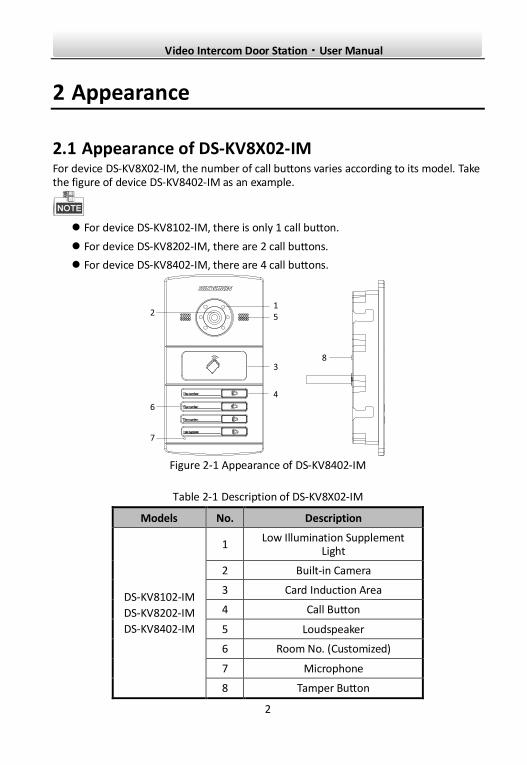
2.1 Appearance of DS-KV8X02-IM For device DS-KV8X02-IM, the number of call buttons varies according to its model. Take the figure of device DS-KV8402-IM as an example.
For device DS-KV8102-IM, there is only 1 call button.
For device DS-KV8202-IM, there are 2 call buttons.
For device DS-KV8402-IM, there are 4 call buttons.
Figure 2-1 Appearance of DS-KV8402-IM
Table 2-1 Description of DS-KV8X02-IM
Models No. Description
DS-KV8102-IM
DS-KV8202-IM
DS-KV8402-IM
1 Low Illumination Supplement
Light
2 Built-in Camera
3 Card Induction Area
4 Call Button
5 Loudspeaker
6 Room No. (Customized)
7 Microphone
8 Tamper Button
Video Intercom Door Station·User Manual
3
You need not customize the Room No. for device DS-KV8102-IM.
Default settings of call button: when you press the call button, it calls the resident;
and when you hold down the call button, it calls the center.
You can change the calling mode of the call button via Batch Configuration Tool or
iVMS-4200 client software. See 7.4.2 Video Intercom for detail steps.
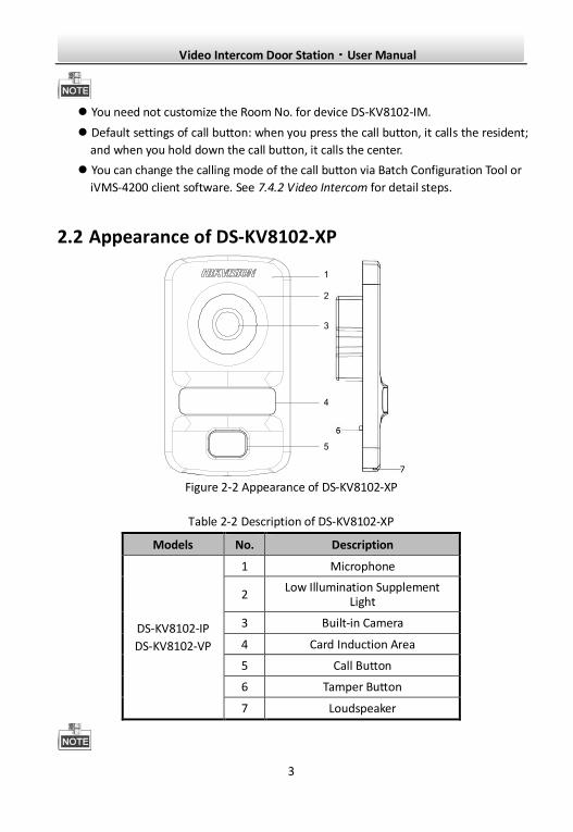
2.2 Appearance of DS-KV8102-XP
1
2
3
4
5
Figure 2-2 Appearance of DS-KV8102-XP
Table 2-2 Description of DS-KV8102-XP
Models No. Description
DS-KV8102-IP
DS-KV8102-VP
1 Microphone
2 Low Illumination Supplement
Light
3 Built-in Camera
4 Card Induction Area
5 Call Button
6 Tamper Button
7 Loudspeaker
Video Intercom Door Station·User Manual
4
Default settings of call button: when you press the call button, it calls the resident;
and when you hold down the call button, it calls the center.
You can change the calling mode of the call button via Batch Configuration Tool or
iVMS-4200 client software. See 7.4.2 Video Intercom for detail steps.
Video Intercom Door Station·User Manual
5
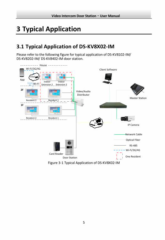
3 Typical Application
3.1 Typical Application of DS-KV8X02-IM
Please refer to the following figure for typical application of DS-KV8102-IM/ DS-KV8202-IM/ DS-KV8402-IM door station.
Master Station
Video/Audio Distributor
Client Software
Door Station
IP CameraLAN
Card Reader
Network Cable
Optical Fiber
One Resident
RS-485
Wi-Fi/3G/4G
Resident 1
1F
2F
Resident 2
Resident 1Resident 2
Indoor Extension 2
Indoor Extension 2
House
Internet
App
Wi-Fi
Wi-Fi/3G/4G
Figure 3-1 Typical Application of DS-KV8X02-IM
Video Intercom Door Station·User Manual
6
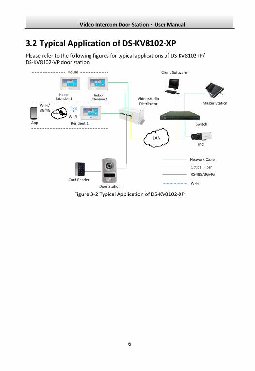
3.2 Typical Application of DS-KV8102-XP
Please refer to the following figures for typical applications of DS-KV8102-IP/ DS-KV8102-VP door station.
Switch
Client Software
Network Cable
Optical Fiber
Door Station
Resident 1
IPC
Video/Audio Distributor
LAN
Indoor Extension 1
Indoor Extension 2
Master Station
Card Reader
RS-485/3G/4G
Wi-Fi
House
Internet
App
Wi-Fi
Wi-Fi/3G/4G
Figure 3-2 Typical Application of DS-KV8102-XP
Video Intercom Door Station·User Manual
7
4 Terminal and Wiring
4.1 Terminal Description
Please refer to the following figure for terminals and interfaces of door station.
①-⑤
⑥-⑦
⑧-⑨
⑩-⑫ ⑬
Figure 4-1 Terminals and Interfaces
Table 4-1 Descriptions of Terminals and Interfaces
Terminals and Interfaces
Name No. Color Description
ALARM IN
1 YELLOW/PURPLE ALARM_1
2 YELLOW/ORANGE ALARM_2
3 YELLOW/GREEN ALARM_3
4 YELLOW/BROWN ALARM_4
5 YELLOW/BLACK ALARM_GND
Power Supply 6 RED DC 12V Power Supply Input
GND 7 BLACK Grounding
RS485 8 ORANGE RS485+
9 YELLOW RS485-
ALARM OUT
10 PINK DR_NC
11 BLUE DR_NO
12 GREEN DR_COM
LAN 13 LAN Network Interface
Video Intercom Door Station·User Manual
8
4 I/O Input terminals (ALARM_1~ALARM_4) can be set as door magnetic input or
door switch key input, and terminal ALARM_GND is for grounding connection.
1 I/O Output terminal can be enabled for controlling electric lock or disabled.
4.2 Wiring Description
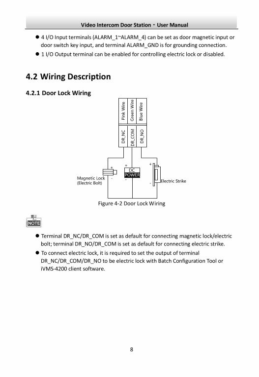
4.2.1 Door Lock Wiring
Figure 4-2 Door Lock Wiring
Terminal DR_NC/DR_COM is set as default for connecting magnetic lock/electric
bolt; terminal DR_NO/DR_COM is set as default for connecting electric strike.
To connect electric lock, it is required to set the output of terminal
DR_NC/DR_COM/DR_NO to be electric lock with Batch Configuration Tool or
iVMS-4200 client software.
Video Intercom Door Station·User Manual
9
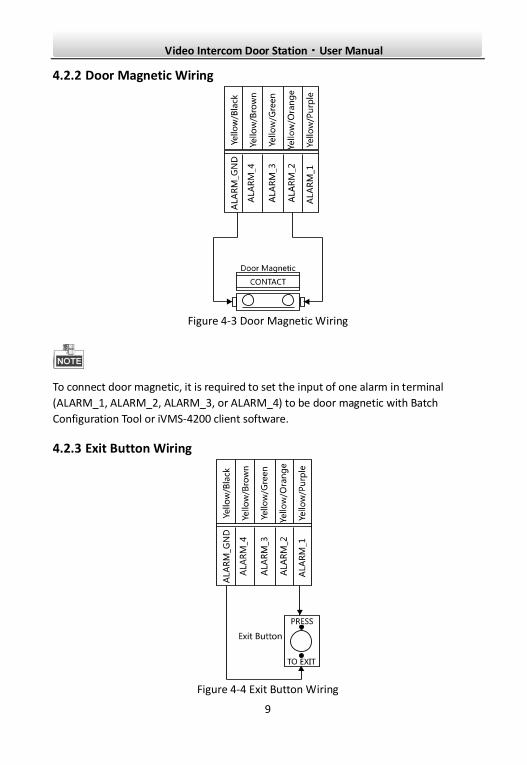
4.2.2 Door Magnetic Wiring
Figure 4-3 Door Magnetic Wiring
To connect door magnetic, it is required to set the input of one alarm in terminal
(ALARM_1, ALARM_2, ALARM_3, or ALARM_4) to be door magnetic with Batch
Configuration Tool or iVMS-4200 client software.
4.2.3 Exit Button Wiring
Figure 4-4 Exit Button Wiring
Video Intercom Door Station·User Manual
10
To connect exit button, it is required to set the input of one alarm in terminal (ALARM_1,
ALARM_2, ALARM_3, or ALARM_4) to be exit button with Batch Configuration Tool or
iVMS-4200 client software.
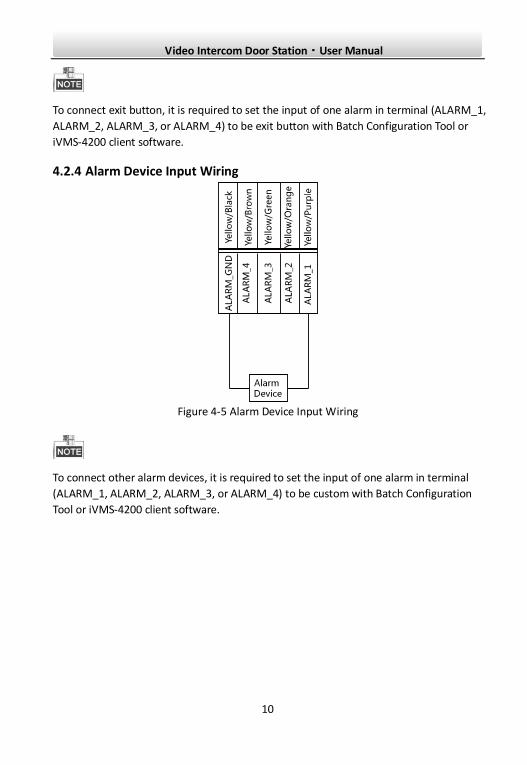
4.2.4 Alarm Device Input Wiring
Figure 4-5 Alarm Device Input Wiring
To connect other alarm devices, it is required to set the input of one alarm in terminal
(ALARM_1, ALARM_2, ALARM_3, or ALARM_4) to be custom with Batch Configuration
Tool or iVMS-4200 client software.
Video Intercom Door Station·User Manual
11
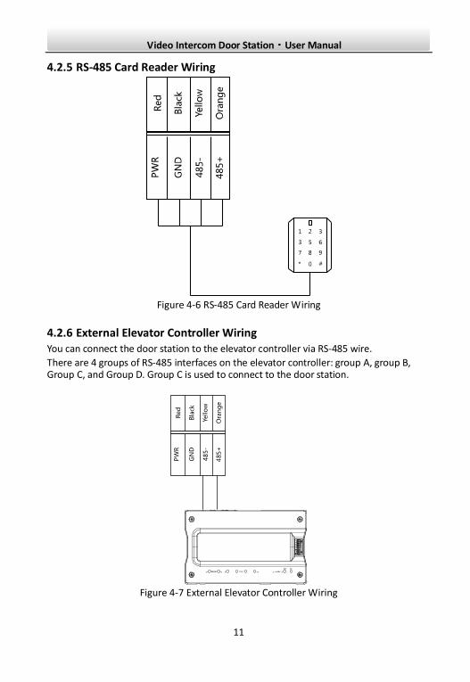
4.2.5 RS-485 Card Reader Wiring
Figure 4-6 RS-485 Card Reader Wiring
4.2.6 External Elevator Controller Wiring You can connect the door station to the elevator controller via RS-485 wire.
There are 4 groups of RS-485 interfaces on the elevator controller: group A, group B, Group C, and Group D. Group C is used to connect to the door station.
Figure 4-7 External Elevator Controller Wiring
Video Intercom Door Station·User Manual
12
5 Installation
5.1 Installation of DS-KV8X02-IM To install the door station onto the wall, you are required to utilize a matched gang box.
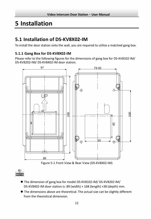
5.1.1 Gang Box for DS-KV8X02-IM Please refer to the following figures for the dimensions of gang box for DS-KV8102-IM/ DS-KV8202-IM/ DS-KV8402-IM door station.
89
16
8
49
54
97
50
45
10
0
73.92
Figure 5-1 Front View & Rear View (DS-KV8X02-IM)
The dimension of gang box for model DS-KV8102-IM/ DS-KV8202-IM/
DS-KV8402-IM door station is: 89 (width) × 168 (length) ×38 (depth) mm.
The dimensions above are theoretical. The actual size can be slightly different
from the theoretical dimension.
Video Intercom Door Station·User Manual
13
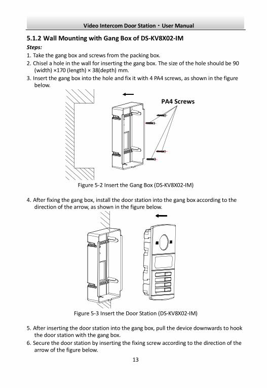
5.1.2 Wall Mounting with Gang Box of DS-KV8X02-IM Steps:
1. Take the gang box and screws from the packing box.
2. Chisel a hole in the wall for inserting the gang box. The size of the hole should be 90 (width) ×170 (length) × 38(depth) mm.
3. Insert the gang box into the hole and fix it with 4 PA4 screws, as shown in the figure below.
PA4 Screws
Figure 5-2 Insert the Gang Box (DS-KV8X02-IM)
4. After fixing the gang box, install the door station into the gang box according to the direction of the arrow, as shown in the figure below.
Figure 5-3 Insert the Door Station (DS-KV8X02-IM)
5. After inserting the door station into the gang box, pull the device downwards to hook the door station with the gang box.
6. Secure the door station by inserting the fixing screw according to the direction of the arrow of the figure below.
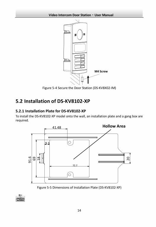
Video Intercom Door Station·User Manual
14
M4 Screw
Figure 5-4 Secure the Door Station (DS-KV8X02-IM)
5.2 Installation of DS-KV8102-XP
5.2.1 Installation Plate for DS-KV8102-XP To install the DS-KV8102-XP model onto the wall, an installation plate and a gang box are required.
20
69
18
41.48
9.3
72.7
Hollow Area
91.
6
Figure 5-5 Dimensions of Installation Plate (DS-KV8102-XP)
Video Intercom Door Station·User Manual
15
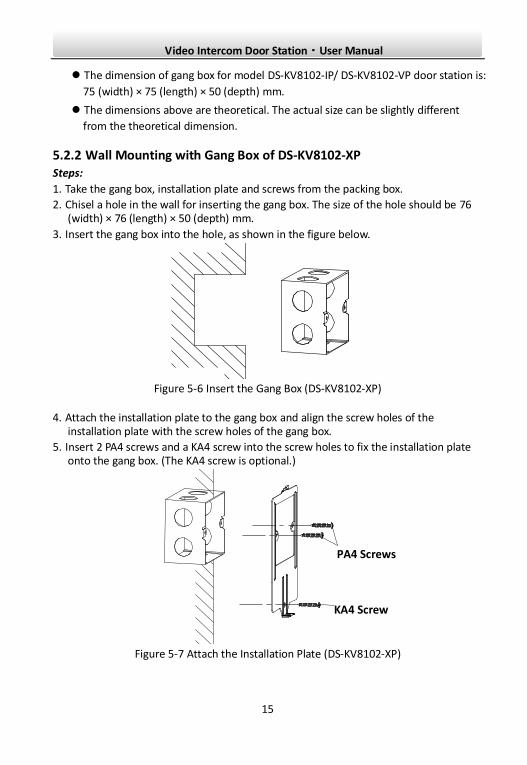
The dimension of gang box for model DS-KV8102-IP/ DS-KV8102-VP door station is:
75 (width) × 75 (length) × 50 (depth) mm.
The dimensions above are theoretical. The actual size can be slightly different
from the theoretical dimension.
5.2.2 Wall Mounting with Gang Box of DS-KV8102-XP Steps:
1. Take the gang box, installation plate and screws from the packing box.
2. Chisel a hole in the wall for inserting the gang box. The size of the hole should be 76 (width) × 76 (length) × 50 (depth) mm.
3. Insert the gang box into the hole, as shown in the figure below.
Figure 5-6 Insert the Gang Box (DS-KV8102-XP)
4. Attach the installation plate to the gang box and align the screw holes of the installation plate with the screw holes of the gang box.
5. Insert 2 PA4 screws and a KA4 screw into the screw holes to fix the installation plate onto the gang box. (The KA4 screw is optional.)
PA4 Screws
KA4 Screw
Figure 5-7 Attach the Installation Plate (DS-KV8102-XP)
Video Intercom Door Station·User Manual
16
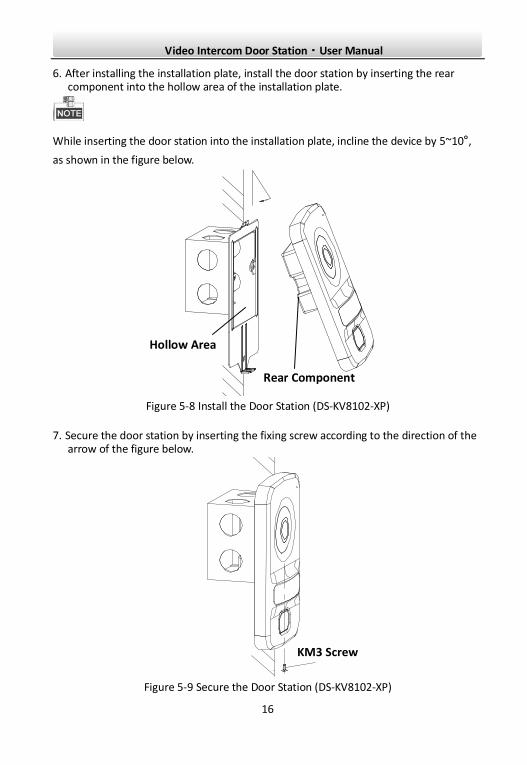
6. After installing the installation plate, install the door station by inserting the rear component into the hollow area of the installation plate.
While inserting the door station into the installation plate, incline the device by 5~10°,
as shown in the figure below.
Hollow Area
Rear Component
Figure 5-8 Install the Door Station (DS-KV8102-XP)
7. Secure the door station by inserting the fixing screw according to the direction of the arrow of the figure below.
KM3 Screw
Figure 5-9 Secure the Door Station (DS-KV8102-XP)
Video Intercom Door Station·User Manual
17
6 Before You Start For the first time use of the device, you are required to activate the device. You can
activate the device and set the device password via internet with Batch Configuration
Tool, or with iVMS-4200 client software, or with Video Intercom Set-up Tool.
To activate the device with Batch Configuration Tool or iVMS-4200, refer to 7
Remote Operation via Batch Configuration Tool and 8 Remote Operation via
iVMS-4200.
Please refer to 7.1 for creating the device password.
Video Intercom Door Station·User Manual
18
7 Remote Operation via Batch Configuration Tool
7.1 Activating Device Remotely Purpose:
You are required to activate the device first by setting a strong password for it before you can use the device.
Activation via Batch Configuration Tool, and Activation via iVMS-4200 are supported. Here take activation via Batch Configuration Tool as example to introduce the device activation. Please refer to the user manual for the activation via iVMS-4200.
Steps:
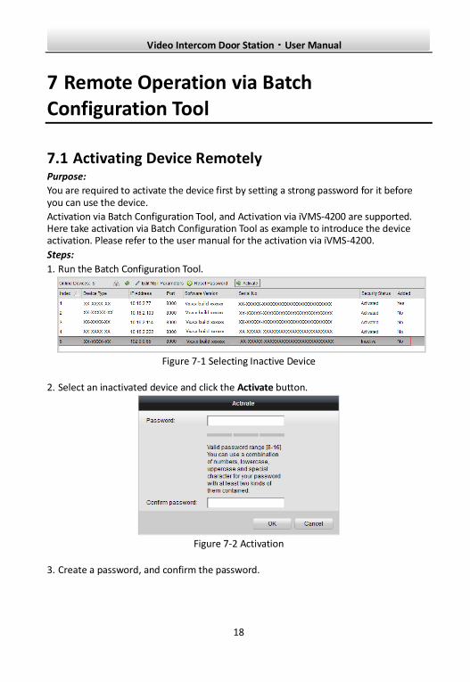
1. Run the Batch Configuration Tool.
Figure 7-1 Selecting Inactive Device
2. Select an inactivated device and click the Activate button.
Figure 7-2 Activation
3. Create a password, and confirm the password.
Video Intercom Door Station·User Manual
19
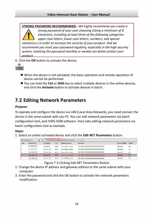
STRONG PASSWORD RECOMMENDED– We highly recommend you create a strong password of your own choosing (Using a minimum of 8 characters, including at least three of the following categories: upper case letters, lower case letters, numbers, and special
characters.) in order to increase the security of your product. And we recommend you reset your password regularly, especially in the high security system, resetting the password monthly or weekly can better protect your product.
4. Click the OK button to activate the device.
When the device is not activated, the basic operation and remote operation of device cannot be performed.
You can hold the Ctrl or Shift key to select multiple devices in the online devices, and click the Activate button to activate devices in batch.
7.2 Editing Network Parameters Purpose:
To operate and configure the device via LAN (Local Area Network), you need connect the
device in the same subnet with you PC. You can edit network parameters via batch
configuration tool, and iVMS-4200 software. Here take editing network parameters via
batch configuration tool as example.
Steps: 1. Select an online activated device and click the Edit NET Parameters button.
Figure 7-3 Clicking Edit NET Parameters Button
2. Change the device IP address and gateway address to the same subnet with your computer.
3. Enter the password and click the OK button to activate the network parameters modification.
Video Intercom Door Station·User Manual
20
Figure 7-4 Editing Network Parameters
The default port No. is 8000.
After editing the network parameters of device, you should add the devices to the
device list again.
7.3 Adding Device Before you start:
Make sure the device to be added has been activated.
Purpose:
For batch configuration tool software, you should add device to the software so as to configure the device remotely.
The software provides 3 ways for adding the devices. You can add the active online devices within your subnet, add devices by IP address, and add devices by IP segment.
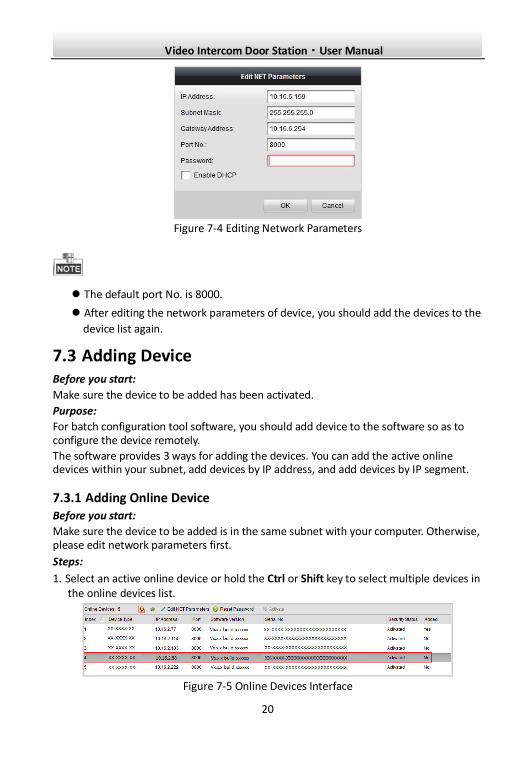
7.3.1 Adding Online Device Before you start:
Make sure the device to be added is in the same subnet with your computer. Otherwise, please edit network parameters first.
Steps:
1. Select an active online device or hold the Ctrl or Shift key to select multiple devices in the online devices list.
Figure 7-5 Online Devices Interface
Video Intercom Door Station·User Manual
21
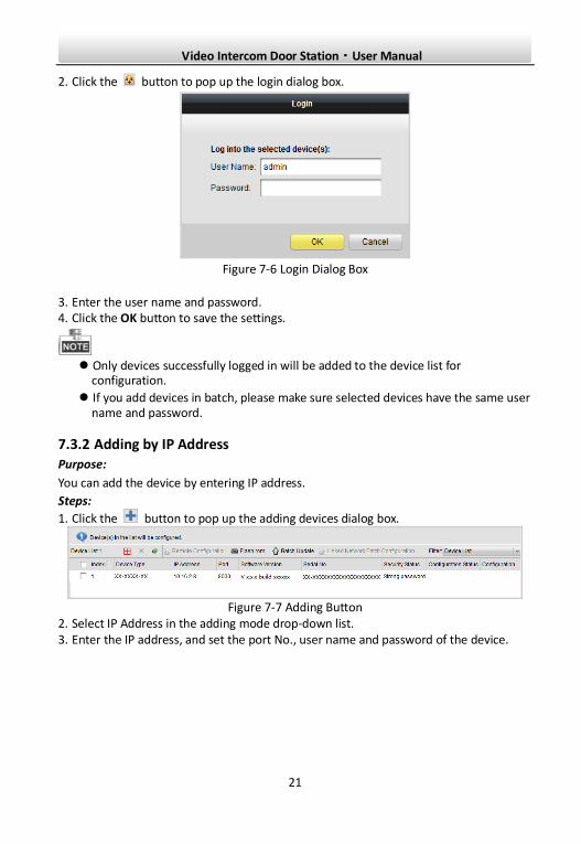
2. Click the button to pop up the login dialog box.
Figure 7-6 Login Dialog Box
3. Enter the user name and password. 4. Click the OK button to save the settings.
Only devices successfully logged in will be added to the device list for
configuration.
If you add devices in batch, please make sure selected devices have the same user name and password.
7.3.2 Adding by IP Address
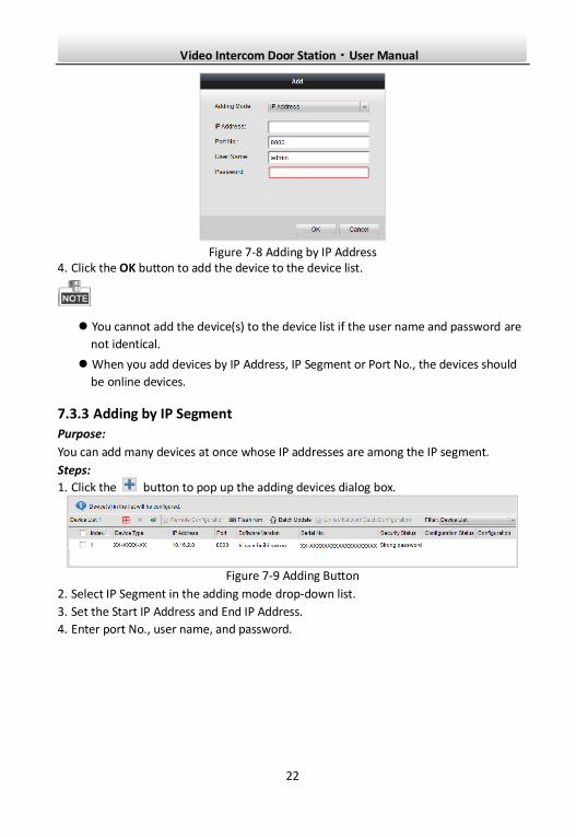
Purpose:
You can add the device by entering IP address.
Steps:
1. Click the button to pop up the adding devices dialog box.
Figure 7-7 Adding Button
2. Select IP Address in the adding mode drop-down list. 3. Enter the IP address, and set the port No., user name and password of the device.
Video Intercom Door Station·User Manual
22
Figure 7-8 Adding by IP Address
4. Click the OK button to add the device to the device list.
You cannot add the device(s) to the device list if the user name and password are
not identical.
When you add devices by IP Address, IP Segment or Port No., the devices should
be online devices.
7.3.3 Adding by IP Segment
Purpose:
You can add many devices at once whose IP addresses are among the IP segment.
Steps:
1. Click the button to pop up the adding devices dialog box.
Figure 7-9 Adding Button
2. Select IP Segment in the adding mode drop-down list.
3. Set the Start IP Address and End IP Address.
4. Enter port No., user name, and password.
Video Intercom Door Station·User Manual
23
Figure 7-10 Adding by IP Segment
5. Click the OK button to search and add the devices whose IP addresses are within the range of the defined IP segment to the device list.
7.4 Configuring Devices Remotely
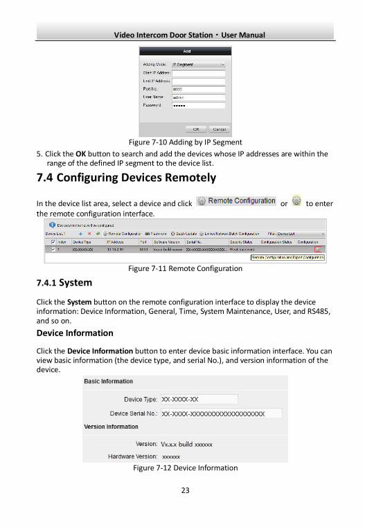
In the device list area, select a device and click or to enter the remote configuration interface.
Figure 7-11 Remote Configuration
7.4.1 System
Click the System button on the remote configuration interface to display the device information: Device Information, General, Time, System Maintenance, User, and RS485, and so on.
Device Information
Click the Device Information button to enter device basic information interface. You can view basic information (the device type, and serial No.), and version information of the device.
Figure 7-12 Device Information
Video Intercom Door Station·User Manual
24
General
Click the General button to enter device general parameters settings interface. You can view and edit the device name and device ID.
Figure 7-13 General
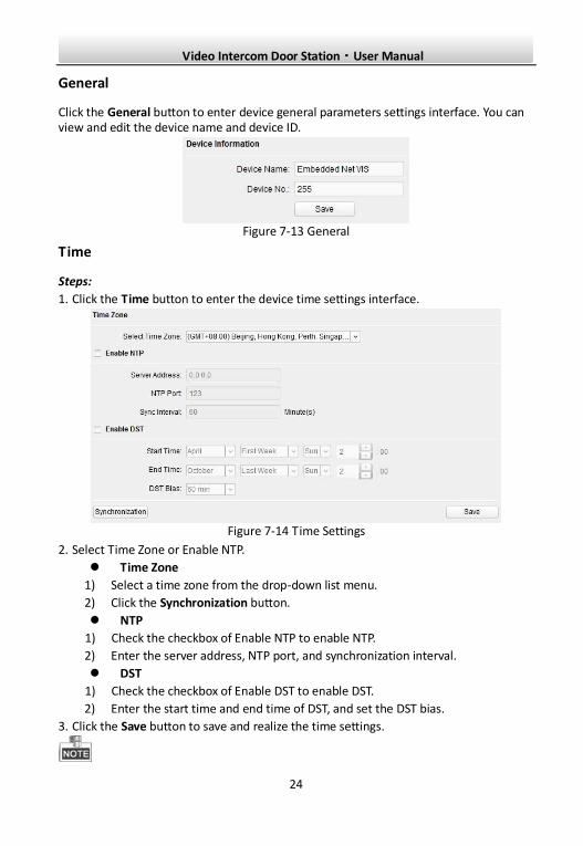
Time
Steps:
1. Click the Time button to enter the device time settings interface.
Figure 7-14 Time Settings
2. Select Time Zone or Enable NTP.
Time Zone
1) Select a time zone from the drop-down list menu.
2) Click the Synchronization button.
NTP
1) Check the checkbox of Enable NTP to enable NTP.
2) Enter the server address, NTP port, and synchronization interval.
DST
1) Check the checkbox of Enable DST to enable DST.
2) Enter the start time and end time of DST, and set the DST bias.
3. Click the Save button to save and realize the time settings.
Video Intercom Door Station·User Manual
25
The default port No. is 123.
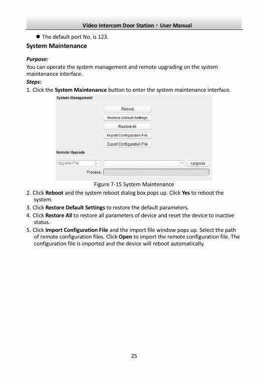
System Maintenance
Purpose:
You can operate the system management and remote upgrading on the system maintenance interface.
Steps:
1. Click the System Maintenance button to enter the system maintenance interface.
Figure 7-15 System Maintenance
2. Click Reboot and the system reboot dialog box pops up. Click Yes to reboot the system.
3. Click Restore Default Settings to restore the default parameters.
4. Click Restore All to restore all parameters of device and reset the device to inactive status.
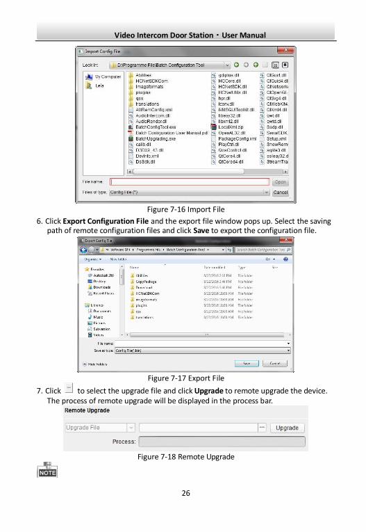
5. Click Import Configuration File and the import file window pops up. Select the path of remote configuration files. Click Open to import the remote configuration file. The configuration file is imported and the device will reboot automatically.
Video Intercom Door Station·User Manual
26
Figure 7-16 Import File
6. Click Export Configuration File and the export file window pops up. Select the saving path of remote configuration files and click Save to export the configuration file.
Figure 7-17 Export File
7. Click to select the upgrade file and click Upgrade to remote upgrade the device. The process of remote upgrade will be displayed in the process bar.
Figure 7-18 Remote Upgrade
Video Intercom Door Station·User Manual
27
Click Restore Default Settings button, all default settings, excluding network parameters, will be restored.
Click Restore All button, all default settings, including network parameters, will be restored. The device will be reset to inactivated status.
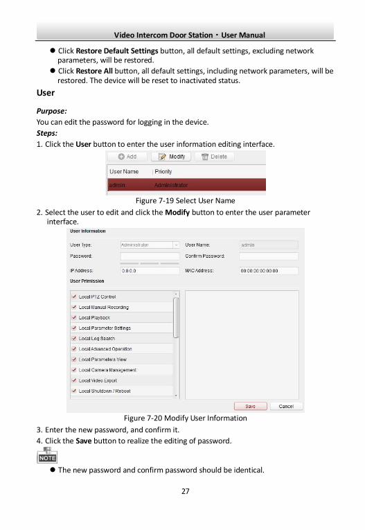
User
Purpose:
You can edit the password for logging in the device.
Steps:
1. Click the User button to enter the user information editing interface.
Figure 7-19 Select User Name
2. Select the user to edit and click the Modify button to enter the user parameter interface.
Figure 7-20 Modify User Information
3. Enter the new password, and confirm it.
4. Click the Save button to realize the editing of password.
The new password and confirm password should be identical.
Video Intercom Door Station·User Manual
28
After editing the password of device, click button from the device list, the added device will not be there. You should add the device again with new password to operate the remote configuration.
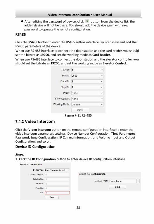
RS485
Click the RS485 button to enter the RS485 setting interface. You can view and edit the RS485 parameters of the device.
When use RS-485 interface to connect the door station and the card reader, you should set the bitrate as 19200, and set the working mode as Card Reader.
When use RS-485 interface to connect the door station and the elevator controller, you should set the bitrate as 19200, and set the working mode as Elevator Control.
Figure 7-21 RS-485
7.4.2 Video Intercom
Click the Video Intercom button on the remote configuration interface to enter the video intercom parameters settings: Device Number Configuration, Time Parameters, Password, Zone Configuration, IP Camera Information, and Volume Input and Output Configuration, and so on.
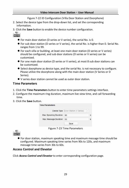
Device ID Configuration
Steps:
1. Click the ID Configuration button to enter device ID configuration interface.
Video Intercom Door Station·User Manual
29
Figure 7-22 ID Configuration (Villa Door Station and Doorphone)
2. Select the device type from the drop-down list, and set the corresponding information.
3. Click the Save button to enable the device number configuration.
For main door station (D series or V series), the serial No. is 0.
For sub door station (D series or V series), the serial No. is higher than 0. Serial No. ranges from 1 to 99.
For each villa or building, at least one main door station (D series or V series) should be configured, and sub door stations (D series or V series) can be customized.
For one main door station (D series or V series), at most 8 sub door stations can be customized.
Select doorphone as device type, and the serial No. is not necessary to configure. Please utilize the doorphone along with the main door station (V Series or D Series).
V series door station cannot be used as outer door station.
Time Parameters
1. Click the Time Parameters button to enter time parameters settings interface.
2. Configure the maximum ring duration, maximum live view time, and call forwarding time.
3. Click the Save button.
Figure 7-23 Time Parameters
For door station, maximum speaking time and maximum message time should be
configured. Maximum speaking time varies from 90s to 120s, and maximum message time varies from 30s to 60s.
Access Control and Elevator
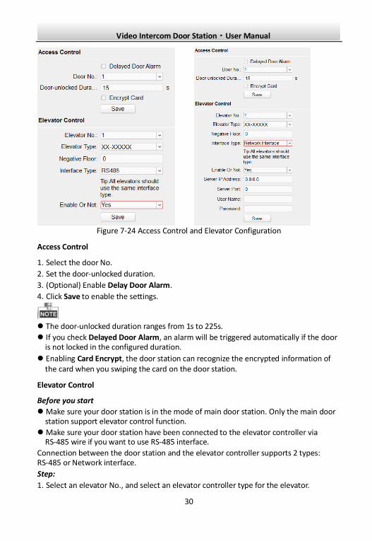
Click Access Control and Elevator to enter corresponding configuration page.
Video Intercom Door Station·User Manual
30
Figure 7-24 Access Control and Elevator Configuration
Access Control
1. Select the door No.
2. Set the door-unlocked duration.
3. (Optional) Enable Delay Door Alarm.
4. Click Save to enable the settings.
The door-unlocked duration ranges from 1s to 225s.
If you check Delayed Door Alarm, an alarm will be triggered automatically if the door is not locked in the configured duration.
Enabling Card Encrypt, the door station can recognize the encrypted information of the card when you swiping the card on the door station.
Elevator Control
Before you start
Make sure your door station is in the mode of main door station. Only the main door station support elevator control function.
Make sure your door station have been connected to the elevator controller via RS-485 wire if you want to use RS-485 interface.
Connection between the door station and the elevator controller supports 2 types: RS-485 or Network interface.
Step:
1. Select an elevator No., and select an elevator controller type for the elevator.
Video Intercom Door Station·User Manual
31
2. Set the negative floor.
3. Select the interface type: RS-485 or Network Interface.
If you select RS-485, please make sure you have connected the door station to the elevator controller with RS-485 wire.
If you select Network Interface, please enter the elevator controller ’s IP address, port No., user name, and password.
4. Enable the elevator control.
Up to 4 elevator controllers can be connected to one door station.
Up to 10 negative floors can be added.
Make sure the interface types of elevator controllers, which are connected to the same door station, are consistent.
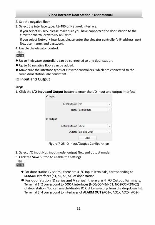
IO Input and Output
Step:
1. Click the I/O Input and Output button to enter the I/O input and output interface.
Figure 7-25 IO Input/Output Configuration
2. Select I/O input No., input mode, output No., and output mode.
3. Click the Save button to enable the settings.
For door station (V series), there are 4 I/O Input Terminals, corresponding to SENSOR interfaces (S1, S2, S3, S4) of door station.
For door station (D series and V series), there are 4 I/O Output Terminals. Terminal 1~2 correspond to DOOR interfaces (NO1/COM1/NC1; NO2/COM2/NC2) of door station. You can enable/disable IO Out by selecting from the dropdown list. Terminal 3~4 correspond to interfaces of ALARM OUT (AO1+, AO1-; AO2+, AO2-).
Video Intercom Door Station·User Manual
32
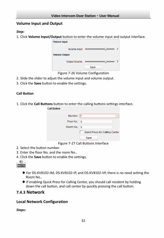
Volume Input and Output
Step:
1. Click Volume Input/Output button to enter the volume input and output interface.
Figure 7-26 Volume Configuration
2. Slide the slider to adjust the volume input and volume output.
3. Click the Save button to enable the settings.
Call Button
1. Click the Call Buttons button to enter the calling buttons settings interface.
Figure 7-27 Call Buttons Interface
2. Select the button number. 3. Enter the floor No. and the room No.. 4. Click the Save button to enable the settings.
For DS-KV8102-IM, DS-KV8102-IP, and DS-KV8102-VP, there is no need setting the Room No..
If enabling Quick Press for Calling Center, you should call resident by holding down the call button, and call center by quickly pressing the call button.
7.4.3 Network
Local Network Configuration
Steps:
Video Intercom Door Station·User Manual
33
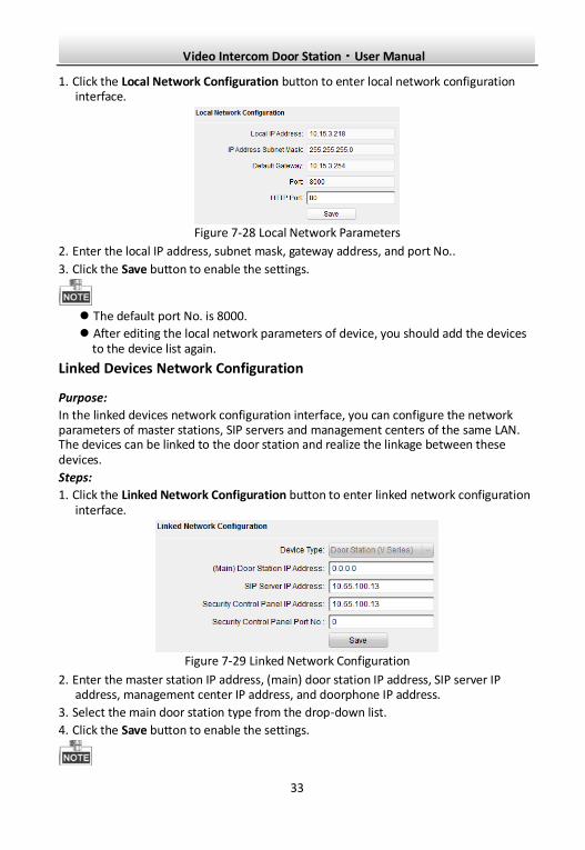
1. Click the Local Network Configuration button to enter local network configuration interface.
Figure 7-28 Local Network Parameters
2. Enter the local IP address, subnet mask, gateway address, and port No..
3. Click the Save button to enable the settings.
The default port No. is 8000.
After editing the local network parameters of device, you should add the devices to the device list again.
Linked Devices Network Configuration
Purpose:
In the linked devices network configuration interface, you can configure the network parameters of master stations, SIP servers and management centers of the same LAN. The devices can be linked to the door station and realize the linkage between these devices.
Steps:
1. Click the Linked Network Configuration button to enter linked network configuration interface.
Figure 7-29 Linked Network Configuration
2. Enter the master station IP address, (main) door station IP address, SIP server IP address, management center IP address, and doorphone IP address.
3. Select the main door station type from the drop-down list.
4. Click the Save button to enable the settings.
Video Intercom Door Station·User Manual
34
After adding master station IP Address, the linkage between indoor station and master station can be realized.
After adding the door station IP Address, the video intercom between indoor stations of same building can be realized.
After adding SIP Server Address IP, the video intercom of same community: video intercom between indoor stations of different building, calling indoor station from outer door station and video intercom between management center and indoors.
After adding management center IP Address, the events can be uploaded to the management center.
For indoor extension, only parameter about the main indoor station should be configured.
Advanced Settings
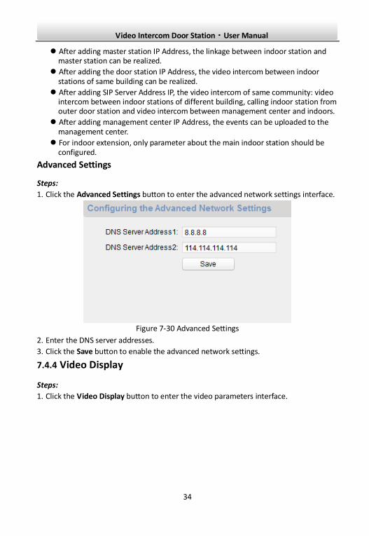
Steps:
1. Click the Advanced Settings button to enter the advanced network settings interface.
Figure 7-30 Advanced Settings
2. Enter the DNS server addresses.
3. Click the Save button to enable the advanced network settings.
7.4.4 Video Display
Steps:
1. Click the Video Display button to enter the video parameters interface.
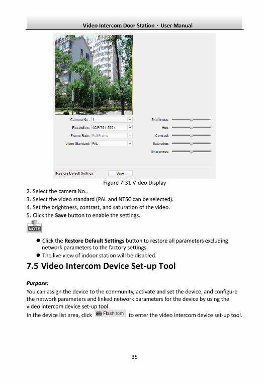
Video Intercom Door Station·User Manual
35
Figure 7-31 Video Display
2. Select the camera No..
3. Select the video standard (PAL and NTSC can be selected).
4. Set the brightness, contrast, and saturation of the video.
5. Click the Save button to enable the settings.
Click the Restore Default Settings button to restore all parameters excluding network parameters to the factory settings.
The live view of indoor station will be disabled.
7.5 Video Intercom Device Set-up Tool
Purpose:
You can assign the device to the community, activate and set the device, and configure the network parameters and linked network parameters for the device by using the video intercom device set-up tool.
In the device list area, click to enter the video intercom device set-up tool.
Video Intercom Door Station·User Manual
36
Figure 7-32 Video Device Set-up Tool
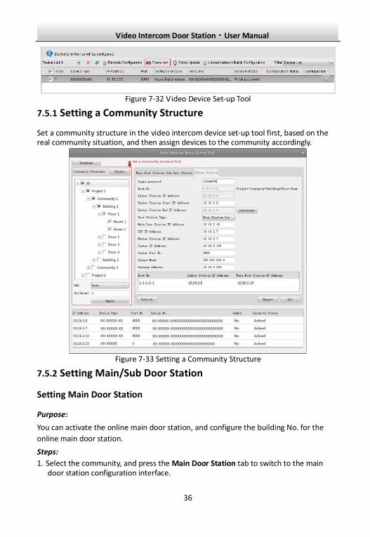
7.5.1 Setting a Community Structure
Set a community structure in the video intercom device set-up tool first, based on the real community situation, and then assign devices to the community accordingly.
Figure 7-33 Setting a Community Structure
7.5.2 Setting Main/Sub Door Station
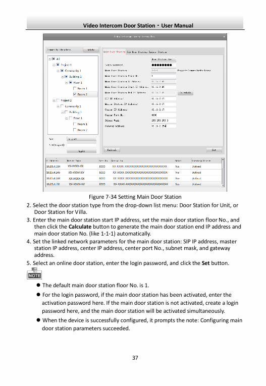
Setting Main Door Station
Purpose:
You can activate the online main door station, and configure the building No. for the
online main door station.
Steps:
1. Select the community, and press the Main Door Station tab to switch to the main door station configuration interface.
Video Intercom Door Station·User Manual
37
Figure 7-34 Setting Main Door Station
2. Select the door station type from the drop-down list menu: Door Station for Unit, or Door Station for Villa.
3. Enter the main door station start IP address, set the main door station floor No., and then click the Calculate button to generate the main door station end IP address and main door station No. (like 1-1-1) automatically.
4. Set the linked network parameters for the main door station: SIP IP address, master station IP address, center IP address, center port No., subnet mask, and gateway address.
5. Select an online door station, enter the login password, and click the Set button.
The default main door station floor No. is 1.
For the login password, if the main door station has been activated, enter the
activation password here. If the main door station is not activated, create a login
password here, and the main door station will be activated simultaneously.
When the device is successfully configured, it prompts the note: Configuring main
door station parameters succeeded.
Video Intercom Door Station·User Manual
38
Setting Sub Door Station
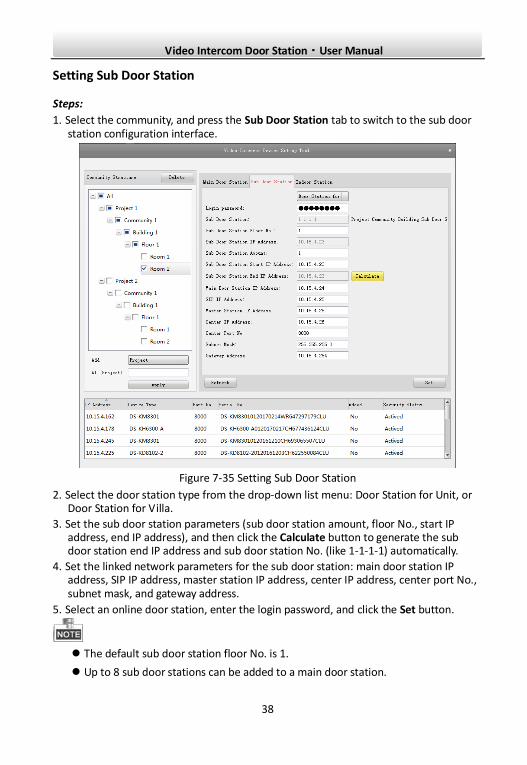
Steps:
1. Select the community, and press the Sub Door Station tab to switch to the sub door station configuration interface.
Figure 7-35 Setting Sub Door Station
2. Select the door station type from the drop-down list menu: Door Station for Unit, or Door Station for Villa.
3. Set the sub door station parameters (sub door station amount, floor No., start IP address, end IP address), and then click the Calculate button to generate the sub door station end IP address and sub door station No. (like 1-1-1-1) automatically.
4. Set the linked network parameters for the sub door station: main door station IP address, SIP IP address, master station IP address, center IP address, center port No., subnet mask, and gateway address.
5. Select an online door station, enter the login password, and click the Set button.
The default sub door station floor No. is 1.
Up to 8 sub door stations can be added to a main door station.
Video Intercom Door Station·User Manual
39
For the login password, if the sub door station has been activated, enter the
activation password here. If the sub door station is not activated, create a login
password here, and the sub door station will be activated simultaneously.
When the device is successfully configured, it prompts the note: Configuring main
door station parameters succeeded
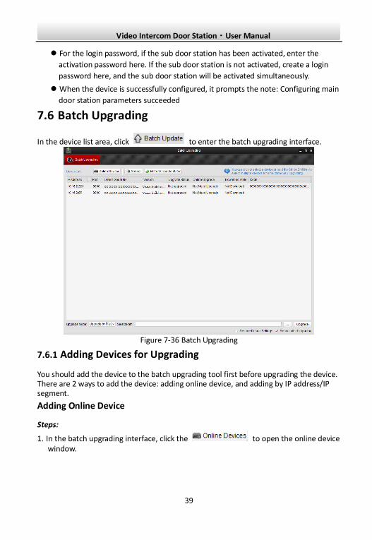
7.6 Batch Upgrading
In the device list area, click to enter the batch upgrading interface.
Figure 7-36 Batch Upgrading
7.6.1 Adding Devices for Upgrading
You should add the device to the batch upgrading tool first before upgrading the device. There are 2 ways to add the device: adding online device, and adding by IP address/IP segment.
Adding Online Device
Steps:
1. In the batch upgrading interface, click the to open the online device window.
Video Intercom Door Station·User Manual
40
Figure 7-37 Login
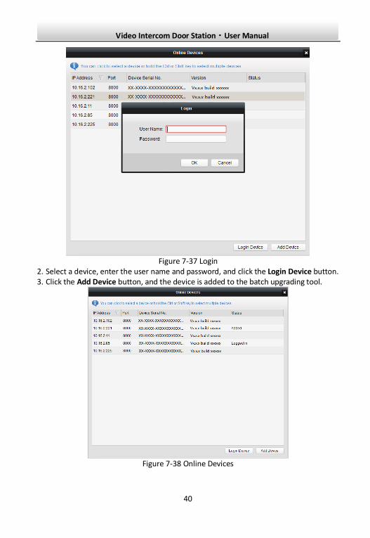
2. Select a device, enter the user name and password, and click the Login Device button. 3. Click the Add Device button, and the device is added to the batch upgrading tool.
Figure 7-38 Online Devices
Video Intercom Door Station·User Manual
41
Adding by IP Address/IP Segment
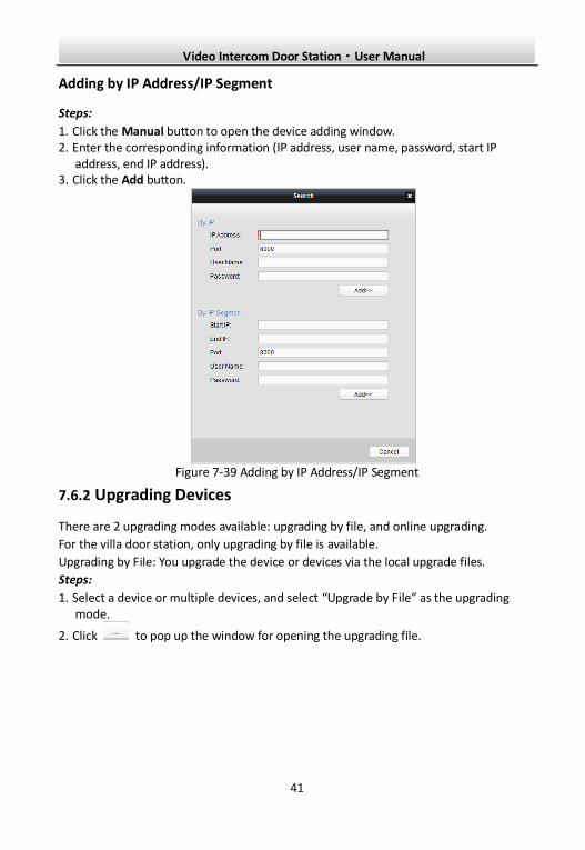
Steps:
1. Click the Manual button to open the device adding window. 2. Enter the corresponding information (IP address, user name, password, start IP
address, end IP address). 3. Click the Add button.
Figure 7-39 Adding by IP Address/IP Segment
7.6.2 Upgrading Devices
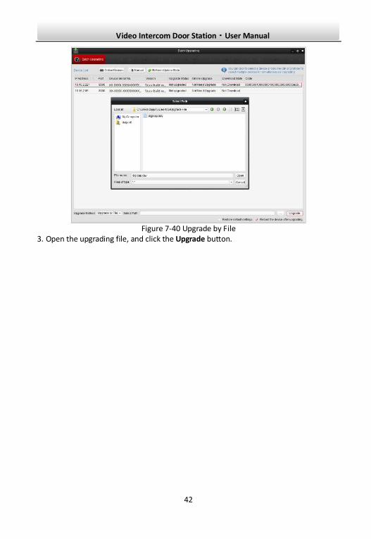
There are 2 upgrading modes available: upgrading by file, and online upgrading.
For the villa door station, only upgrading by file is available.
Upgrading by File: You upgrade the device or devices via the local upgrade files.
Steps:
1. Select a device or multiple devices, and select “Upgrade by File” as the upgrading mode.
2. Click to pop up the window for opening the upgrading file.
Video Intercom Door Station·User Manual
42
Figure 7-40 Upgrade by File
3. Open the upgrading file, and click the Upgrade button.
Video Intercom Door Station·User Manual
43
8 Remote Operation via iVMS-4200 The Video Intercom module provides remote control and configuration on video intercom products via the iVMS-4200 client software.
Before remote configure and control the video intercom, you are required to add the device to the software first. Refer to 8.2 Device Management.
For remote configuration of video intercom device via the iVMS-4200 client software, refer to 8.3 Configuring Devices Remotely via iVMS-4200.
For the picture storage on storage server, refer to 8.4 Picture Storage.
For remote control of video intercom devices, please refer to 8.5 Video Intercom Configuration.
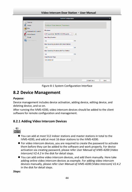
8.1 System Configuration Purpose:
You can configure the video intercom parameters accordingly.
Steps:
1. Open the System Configuration page.
Path: Control Panel -> Maintenance and Management -> System Configuration -> Video Intercom.
2. Click the Video Intercom tab to enter the Video Intercom Settings interface.
3. Input the required information.
Ringtone: Click the icon and select the audio file from the local path for the
ringtone of indoor station. Optionally, you can click the icon for a testing of the audio file.
Max. Ring Duration: Input the maximum duration of the ringtone, ranging from 15 seconds to 60 seconds.
Max. Speaking Duration with Indoor Station: Input the maximum duration of speaking with the indoor station, ranging from 120 seconds to 600 seconds.
Max. Speaking Duration with Door Station: Input the maximum duration of speaking with the door station, ranging from 90 seconds to 120 seconds.
Card Reader Type: Select the card reader to issue cards.
4. Click Save to save the settings.
Video Intercom Door Station·User Manual
44
Figure 8-1 System Configuration Interface
8.2 Device Management Purpose:
Device management includes device activation, adding device, editing device, and deleting device, and so on.
After running the iVMS-4200, video intercom devices should be added to the client software for remote configuration and management.
8.2.1 Adding Video Intercom Devices
You can add at most 512 indoor stations and master stations in total to the
iVMS-4200, and add at most 16 door stations to the iVMS-4200.
For video intercom devices, you are required to create the password to activate them before they can be added to the software and work properly. For device activation via creating password, please refer User Manual of iVMS-4200 (Video Intercom) V2.4.2 in the disk for detail steps.
You can add online video intercom devices, and add them manually. Here take adding online video intercom devices as example. For adding video intercom devices manually, please refer User Manual of iVMS-4200 (Video Intercom) V2.4.2 in the disk for detail steps.
Steps:
Video Intercom Door Station·User Manual
45
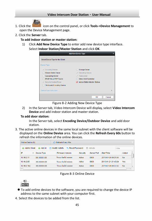
1. Click the icon on the control panel, or click Tools->Device Management to open the Device Management page.
2. Click the Server tab.
To add indoor station or master station:
1) Click Add New Device Type to enter add new device type interface.
Select Indoor Station/Master Station and click OK.
Figure 8-2 Adding New Device Type
2) In the Server tab, Video Intercom Device will display, select Video Intercom Device and add indoor station and master station.
To add door station:
In the Server tab, select Encoding Device/Outdoor Device and add door station.
3. The active online devices in the same local subnet with the client software will be displayed on the Online Device area. You can click the Refresh Every 60s button to refresh the information of the online devices.
Figure 8-3 Online Device
To add online devices to the software, you are required to change the device IP
address to the same subnet with your computer first.
4. Select the devices to be added from the list.
Video Intercom Door Station·User Manual
46
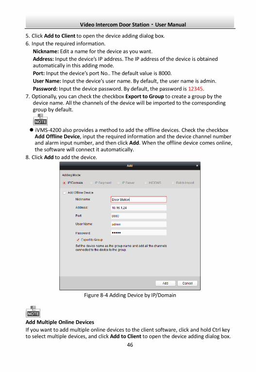
5. Click Add to Client to open the device adding dialog box.
6. Input the required information.
Nickname: Edit a name for the device as you want.
Address: Input the device’s IP address. The IP address of the device is obtained automatically in this adding mode.
Port: Input the device’s port No.. The default value is 8000.
User Name: Input the device’s user name. By default, the user name is admin.
Password: Input the device password. By default, the password is 12345.
7. Optionally, you can check the checkbox Export to Group to create a group by the device name. All the channels of the device will be imported to the corresponding group by default.
iVMS-4200 also provides a method to add the offline devices. Check the checkbox
Add Offline Device, input the required information and the device channel number and alarm input number, and then click Add. When the offline device comes online, the software will connect it automatically.
8. Click Add to add the device.
Figure 8-4 Adding Device by IP/Domain
Add Multiple Online Devices
If you want to add multiple online devices to the client software, click and hold Ctrl key to select multiple devices, and click Add to Client to open the device adding dialog box.
Video Intercom Door Station·User Manual
47
In the pop-up message box, enter the user name and password for the devices to be added.
Add All the Online Devices
If you want to add all the online devices to the client software, click Add All and click OK in the pop-up message box. Then enter the user name and password for the devices to be added.
8.2.2 Modifying Network Information
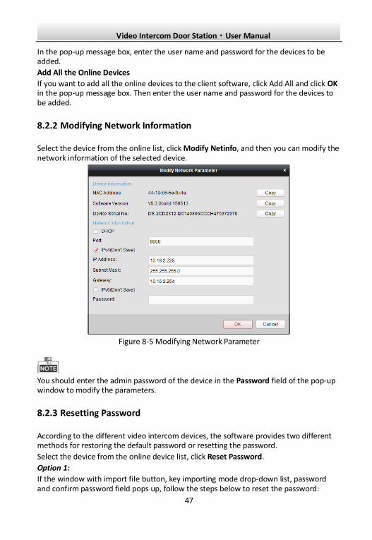
Select the device from the online list, click Modify Netinfo, and then you can modify the network information of the selected device.
Figure 8-5 Modifying Network Parameter
You should enter the admin password of the device in the Password field of the pop-up window to modify the parameters.
8.2.3 Resetting Password
According to the different video intercom devices, the software provides two different methods for restoring the default password or resetting the password.
Select the device from the online device list, click Reset Password.
Option 1:
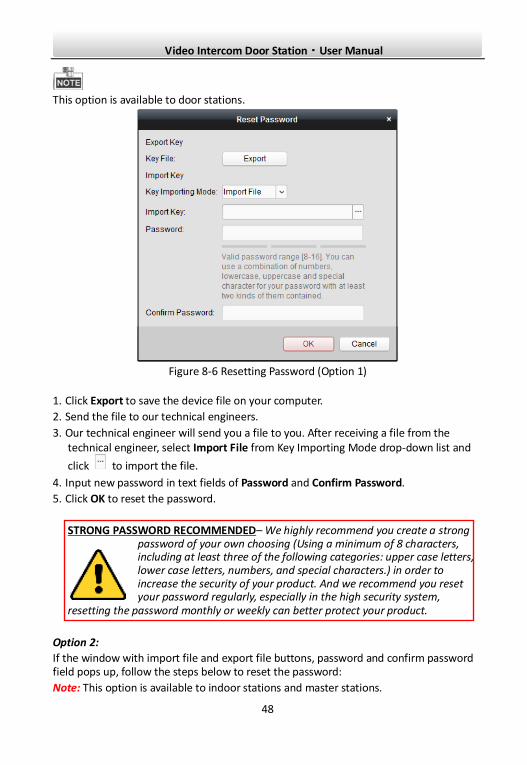
If the window with import file button, key importing mode drop-down list, password and confirm password field pops up, follow the steps below to reset the password:
Video Intercom Door Station·User Manual
48
This option is available to door stations.
Figure 8-6 Resetting Password (Option 1)
1. Click Export to save the device file on your computer.
2. Send the file to our technical engineers.
3. Our technical engineer will send you a file to you. After receiving a file from the technical engineer, select Import File from Key Importing Mode drop-down list and
click to import the file.
4. Input new password in text fields of Password and Confirm Password.
5. Click OK to reset the password.
STRONG PASSWORD RECOMMENDED– We highly recommend you create a strong password of your own choosing (Using a minimum of 8 characters, including at least three of the following categories: upper case letters, lower case letters, numbers, and special characters.) in order to increase the security of your product. And we recommend you reset your password regularly, especially in the high security system,
resetting the password monthly or weekly can better protect your product.
Option 2:
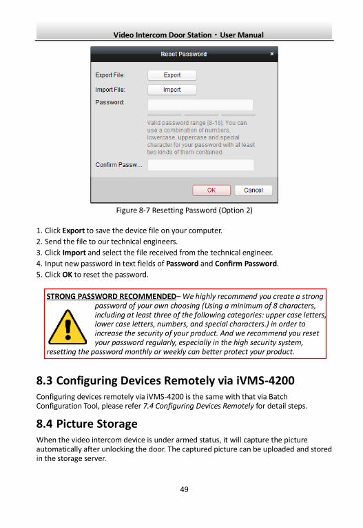
If the window with import file and export file buttons, password and confirm password field pops up, follow the steps below to reset the password:
Note: This option is available to indoor stations and master stations.
Video Intercom Door Station·User Manual
49
Figure 8-7 Resetting Password (Option 2)
1. Click Export to save the device file on your computer.
2. Send the file to our technical engineers.
3. Click Import and select the file received from the technical engineer.
4. Input new password in text fields of Password and Confirm Password.
5. Click OK to reset the password.
STRONG PASSWORD RECOMMENDED– We highly recommend you create a strong password of your own choosing (Using a minimum of 8 characters, including at least three of the following categories: upper case letters, lower case letters, numbers, and special characters.) in order to increase the security of your product. And we recommend you reset your password regularly, especially in the high security system,
resetting the password monthly or weekly can better protect your product.
8.3 Configuring Devices Remotely via iVMS-4200 Configuring devices remotely via iVMS-4200 is the same with that via Batch Configuration Tool, please refer 7.4 Configuring Devices Remotely for detail steps.
8.4 Picture Storage When the video intercom device is under armed status, it will capture the picture automatically after unlocking the door. The captured picture can be uploaded and stored in the storage server.
Video Intercom Door Station·User Manual
50
When starting the live view of door station via iVMS-4200, you can capture the live view picture. The captured picture can be uploaded and stored in the storage server.
This function is only available to door stations.
You are required to add storage server to the iVMS-4200, and format the HDDs first before uploading and storing captured pictures.
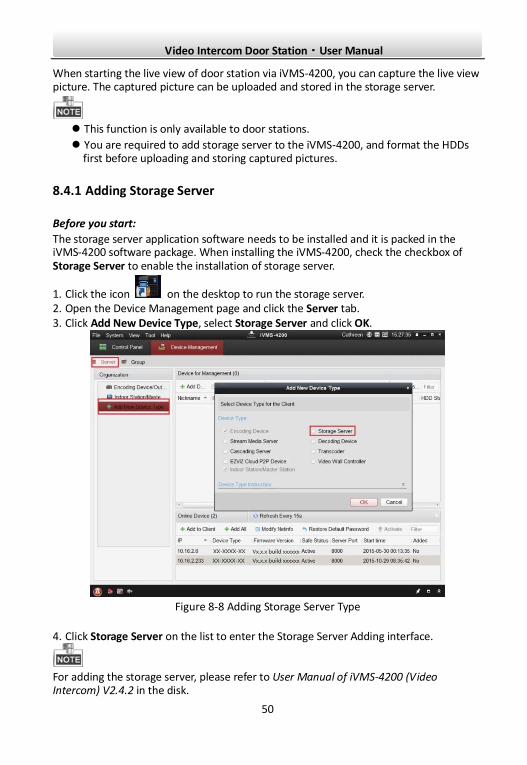
8.4.1 Adding Storage Server
Before you start:
The storage server application software needs to be installed and it is packed in the iVMS-4200 software package. When installing the iVMS-4200, check the checkbox of Storage Server to enable the installation of storage server.
1. Click the icon on the desktop to run the storage server. 2. Open the Device Management page and click the Server tab. 3. Click Add New Device Type, select Storage Server and click OK.
Figure 8-8 Adding Storage Server Type
4. Click Storage Server on the list to enter the Storage Server Adding interface.
For adding the storage server, please refer to User Manual of iVMS-4200 (Video Intercom) V2.4.2 in the disk.
Video Intercom Door Station·User Manual
51
8.4.2 Formatting the HDDs
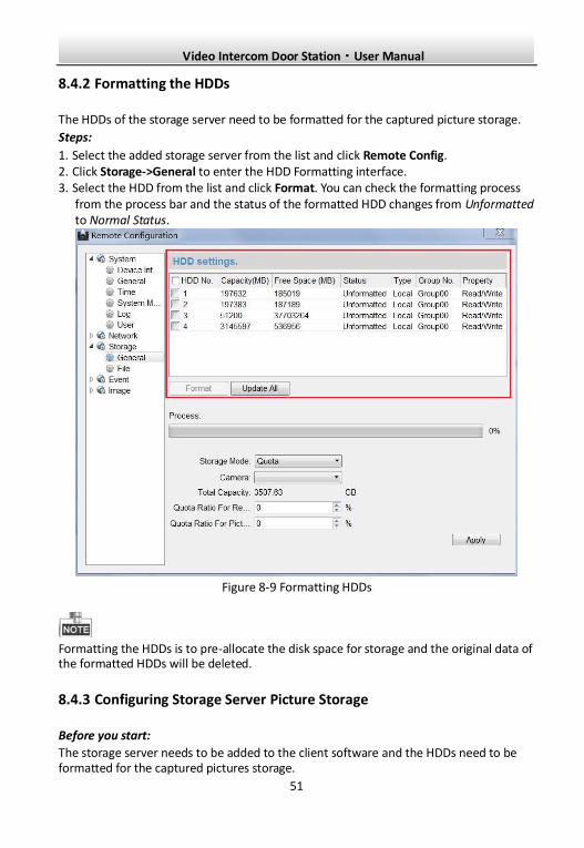
The HDDs of the storage server need to be formatted for the captured picture storage.
Steps:
1. Select the added storage server from the list and click Remote Config. 2. Click Storage->General to enter the HDD Formatting interface. 3. Select the HDD from the list and click Format. You can check the formatting process
from the process bar and the status of the formatted HDD changes from Unformatted to Normal Status.
Figure 8-9 Formatting HDDs
Formatting the HDDs is to pre-allocate the disk space for storage and the original data of the formatted HDDs will be deleted.
8.4.3 Configuring Storage Server Picture Storage
Before you start:
The storage server needs to be added to the client software and the HDDs need to be formatted for the captured pictures storage.
Video Intercom Door Station·User Manual
52
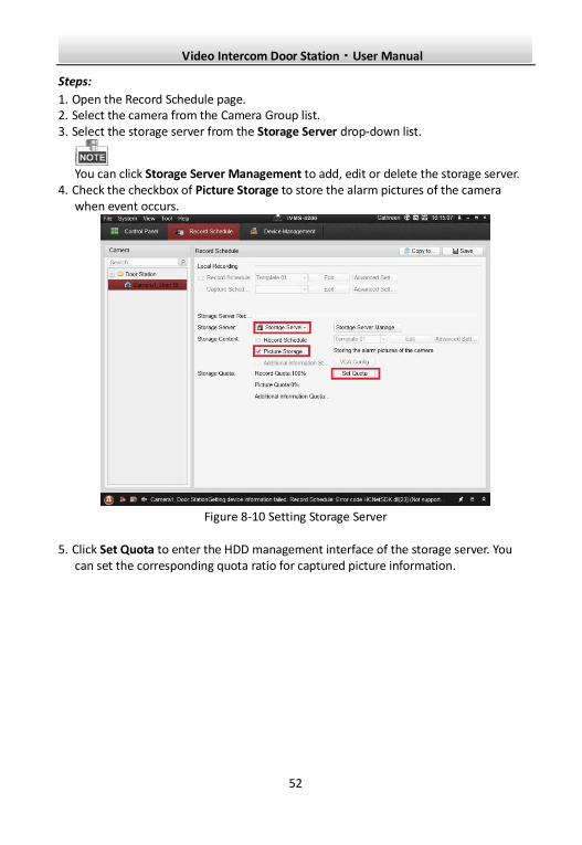
Steps:
1. Open the Record Schedule page. 2. Select the camera from the Camera Group list. 3. Select the storage server from the Storage Server drop-down list.
You can click Storage Server Management to add, edit or delete the storage server.
4. Check the checkbox of Picture Storage to store the alarm pictures of the camera when event occurs.
Figure 8-10 Setting Storage Server
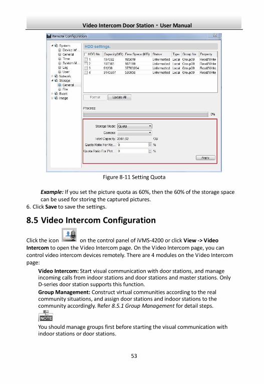
5. Click Set Quota to enter the HDD management interface of the storage server. You can set the corresponding quota ratio for captured picture information.
Video Intercom Door Station·User Manual
53
Figure 8-11 Setting Quota
Example: If you set the picture quota as 60%, then the 60% of the storage space can be used for storing the captured pictures.
6. Click Save to save the settings.
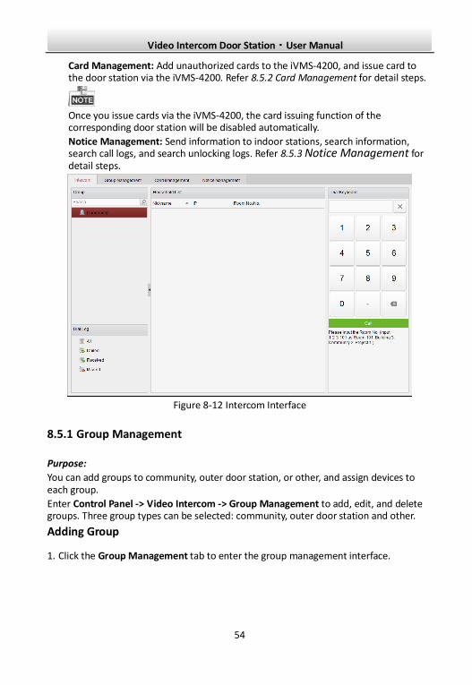
8.5 Video Intercom Configuration
Click the icon on the control panel of iVMS-4200 or click View -> Video Intercom to open the Video Intercom page. On the Video Intercom page, you can control video intercom devices remotely. There are 4 modules on the Video Intercom page:
Video Intercom: Start visual communication with door stations, and manage incoming calls from indoor stations and door stations and master stations. Only D-series door station supports this function.
Group Management: Construct virtual communities according to the real community situations, and assign door stations and indoor stations to the community accordingly. Refer 8.5.1 Group Management for detail steps.
You should manage groups first before starting the visual communication with indoor stations or door stations.
Video Intercom Door Station·User Manual
54
Card Management: Add unauthorized cards to the iVMS-4200, and issue card to the door station via the iVMS-4200. Refer 8.5.2 Card Management for detail steps.
Once you issue cards via the iVMS-4200, the card issuing function of the corresponding door station will be disabled automatically.
Notice Management: Send information to indoor stations, search information, search call logs, and search unlocking logs. Refer 8.5.3 Notice Management for detail steps.
Figure 8-12 Intercom Interface
8.5.1 Group Management
Purpose:
You can add groups to community, outer door station, or other, and assign devices to each group.
Enter Control Panel -> Video Intercom -> Group Management to add, edit, and delete groups. Three group types can be selected: community, outer door station and other.
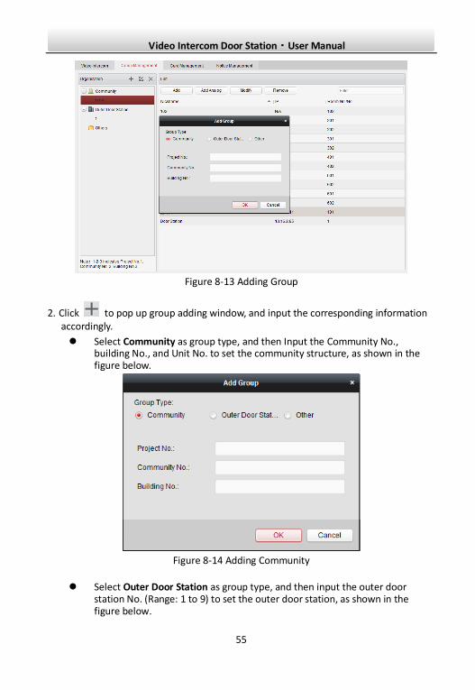
Adding Group
1. Click the Group Management tab to enter the group management interface.
Video Intercom Door Station·User Manual
55
Figure 8-13 Adding Group
2. Click to pop up group adding window, and input the corresponding information accordingly.
Select Community as group type, and then Input the Community No., building No., and Unit No. to set the community structure, as shown in the figure below.
Figure 8-14 Adding Community
Select Outer Door Station as group type, and then input the outer door station No. (Range: 1 to 9) to set the outer door station, as shown in the figure below.
Video Intercom Door Station·User Manual
56
Figure 8-15 Adding Outer Door Station
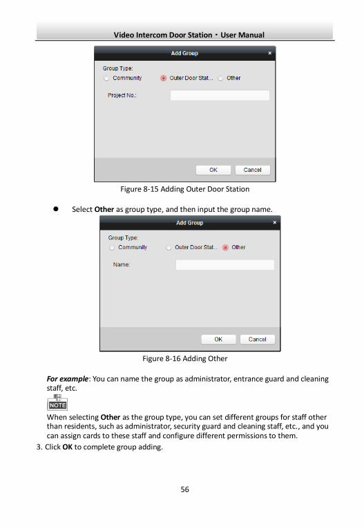
Select Other as group type, and then input the group name.
Figure 8-16 Adding Other
For example: You can name the group as administrator, entrance guard and cleaning staff, etc.
When selecting Other as the group type, you can set different groups for staff other than residents, such as administrator, security guard and cleaning staff, etc., and you can assign cards to these staff and configure different permissions to them.
3. Click OK to complete group adding.
Video Intercom Door Station·User Manual
57
Assigning IP Devices to Group
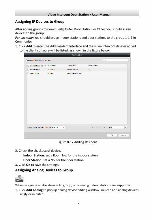
After adding groups to Community, Outer Door Station, or Other, you should assign devices to the group.
For example: You should assign indoor stations and door stations to the group 1-1-1 in Community.
1. Click Add to enter the Add Resident Interface and the video intercom devices added to the client software will be listed, as shown in the figure below.
Figure 8-17 Adding Resident
2. Check the checkbox of device.
Indoor Station: set a Room No. for the indoor station.
Door Station: set a No. for the door station.
3. Click OK to save the settings.
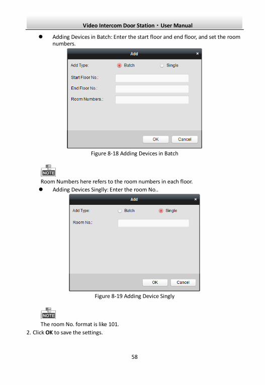
Assigning Analog Devices to Group
When assigning analog devices to group, only analog indoor stations are supported.
1. Click Add Analog to pop up analog device adding window. You can add analog devices singly or in batch.
Video Intercom Door Station·User Manual
58
Adding Devices in Batch: Enter the start floor and end floor, and set the room numbers.
Figure 8-18 Adding Devices in Batch
Room Numbers here refers to the room numbers in each floor.
Adding Devices Singlly: Enter the room No..
Figure 8-19 Adding Device Singly
The room No. format is like 101.
2. Click OK to save the settings.
Video Intercom Door Station·User Manual
59
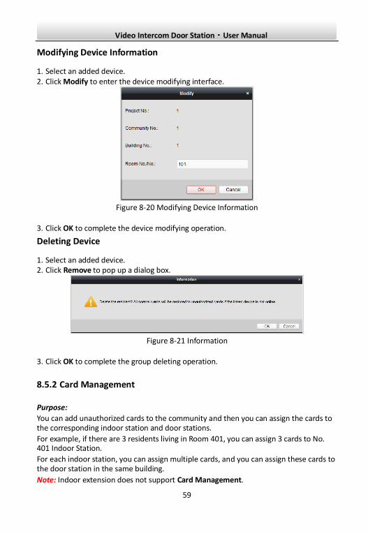
Modifying Device Information
1. Select an added device. 2. Click Modify to enter the device modifying interface.
Figure 8-20 Modifying Device Information
3. Click OK to complete the device modifying operation.
Deleting Device
1. Select an added device. 2. Click Remove to pop up a dialog box.
Figure 8-21 Information
3. Click OK to complete the group deleting operation.
8.5.2 Card Management
Purpose:
You can add unauthorized cards to the community and then you can assign the cards to the corresponding indoor station and door stations.
For example, if there are 3 residents living in Room 401, you can assign 3 cards to No. 401 Indoor Station.
For each indoor station, you can assign multiple cards, and you can assign these cards to the door station in the same building.
Note: Indoor extension does not support Card Management.
Video Intercom Door Station·User Manual
60
Before you start:
Make sure the indoor station and door station have been added to the iVMS-4200 client software.
Steps:
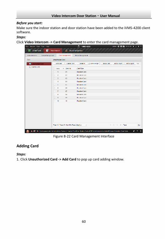
Click Video Intercom -> Card Management to enter the card management page.
Figure 8-22 Card Management Interface
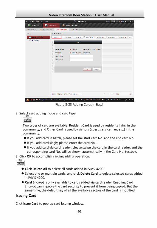
Adding Card
Steps:
1. Click Unauthorized Card -> Add Card to pop up card adding window.
Video Intercom Door Station·User Manual
61
Figure 8-23 Adding Cards in Batch
2. Select card adding mode and card type.
Two types of card are available. Resident Card is used by residents living in the community, and Other Card is used by visitors (guest, serviceman, etc.) in the community.
If you add card in batch, please set the start card No. and the end card No..
If you add card singly, please enter the card No..
If you add card via card reader, please swipe the card in the card reader, and the corresponding card No. will be shown automatically in the Card No. textbox.
3. Click OK to accomplish carding adding operation.
Click Delete All to delete all cards added in iVMS-4200.
Select one or multiple cards, and click Delete Card to delete selected cards added in iVMS-4200.
Card Encrypt is only available to cards added via card reader. Enabling Card Encrypt can improve the card security to prevent it from being copied. But the same time, the default key of all the available sectors of the card is modified.
Issuing Card
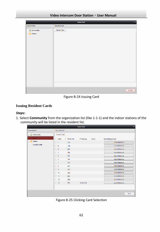
Click Issue Card to pop up card issuing window.
Video Intercom Door Station·User Manual
62
Figure 8-24 Issuing Card
Issuing Resident Cards
Steps:
1. Select Community from the organization list (like 1-1-1) and the indoor stations of the community will be listed in the resident list.
Figure 8-25 Clicking Card Selection
Video Intercom Door Station·User Manual
63
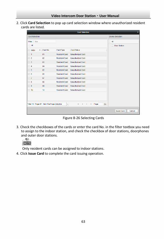
2. Click Card Selection to pop up card selection window where unauthorized resident cards are listed.
Figure 8-26 Selecting Cards
3. Check the checkboxes of the cards or enter the card No. in the filter textbox you need to assign to the indoor station, and check the checkbox of door stations, doorphones and outer door stations.
Only resident cards can be assigned to indoor stations.
4. Click Issue Card to complete the card issuing operation.
Video Intercom Door Station·User Manual
64
Figure 8-27 Displaying Card Issued
After issuing resident cards to the indoor station, the card No. will also be listed in the resident list.
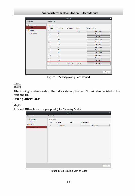
Issuing Other Cards
Steps:
1. Select Other from the group list (like Cleaning Staff).
Figure 8-28 Issuing Other Card
Video Intercom Door Station·User Manual
65
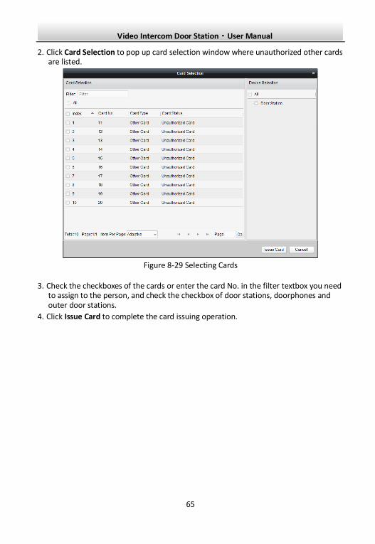
2. Click Card Selection to pop up card selection window where unauthorized other cards are listed.
Figure 8-29 Selecting Cards
3. Check the checkboxes of the cards or enter the card No. in the filter textbox you need to assign to the person, and check the checkbox of door stations, doorphones and outer door stations.
4. Click Issue Card to complete the card issuing operation.
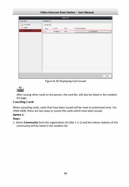
Video Intercom Door Station·User Manual
66
Figure 8-30 Displaying Card Issued
After issuing other cards to the person, the card No. will also be listed in the resident list page.
Canceling Cards
When canceling cards, cards that have been issued will be reset to authorized ones. Via iVMS-4200, there are two ways to cancel the cards which have been issued.
Option 1:
Steps:
1. Select Community from the organization list (like 1-1-1) and the indoor stations of the community will be listed in the resident list.
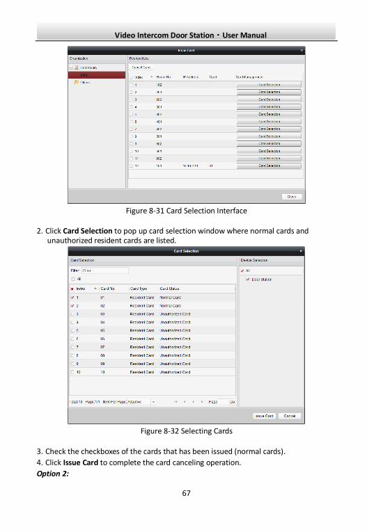
Video Intercom Door Station·User Manual
67
Figure 8-31 Card Selection Interface
2. Click Card Selection to pop up card selection window where normal cards and unauthorized resident cards are listed.
Figure 8-32 Selecting Cards
3. Check the checkboxes of the cards that has been issued (normal cards).
4. Click Issue Card to complete the card canceling operation.
Option 2:
Video Intercom Door Station·User Manual
68
On the card issuing interface, check the checkboxes of Room No. (for resident card) or Name (for other card), click Cancel Card to cancel all card issued to the device.
Through Option 1, you can cancel card from single or certain door stations.
Through Option 2, you will cancel all issued cards at a time.
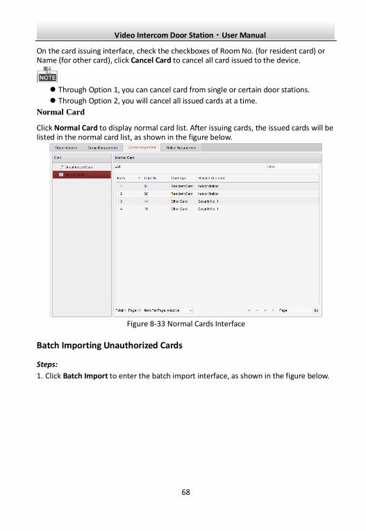
Normal Card
Click Normal Card to display normal card list. After issuing cards, the issued cards will be listed in the normal card list, as shown in the figure below.
Figure 8-33 Normal Cards Interface
Batch Importing Unauthorized Cards
Steps:
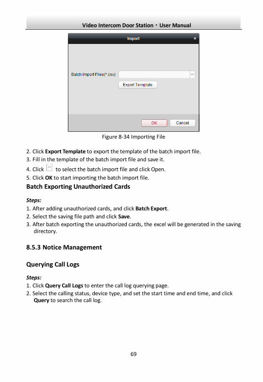
1. Click Batch Import to enter the batch import interface, as shown in the figure below.
Video Intercom Door Station·User Manual
69
Figure 8-34 Importing File
2. Click Export Template to export the template of the batch import file.
3. Fill in the template of the batch import file and save it.
4. Click to select the batch import file and click Open.
5. Click OK to start importing the batch import file.
Batch Exporting Unauthorized Cards
Steps:
1. After adding unauthorized cards, and click Batch Export.
2. Select the saving file path and click Save.
3. After batch exporting the unauthorized cards, the excel will be generated in the saving directory.
8.5.3 Notice Management
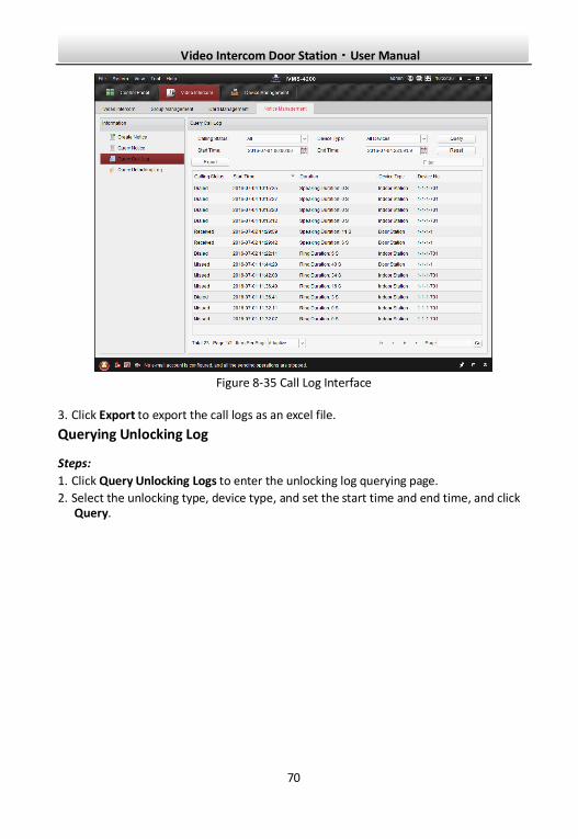
Querying Call Logs
Steps:
1. Click Query Call Logs to enter the call log querying page.
2. Select the calling status, device type, and set the start time and end time, and click Query to search the call log.
Video Intercom Door Station·User Manual
70
Figure 8-35 Call Log Interface
3. Click Export to export the call logs as an excel file.
Querying Unlocking Log
Steps:
1. Click Query Unlocking Logs to enter the unlocking log querying page.
2. Select the unlocking type, device type, and set the start time and end time, and click Query.
Video Intercom Door Station·User Manual
71
Figure 8-36 Unlocking Log Interface
3. Click Export to export the unlocking logs as an excel file.
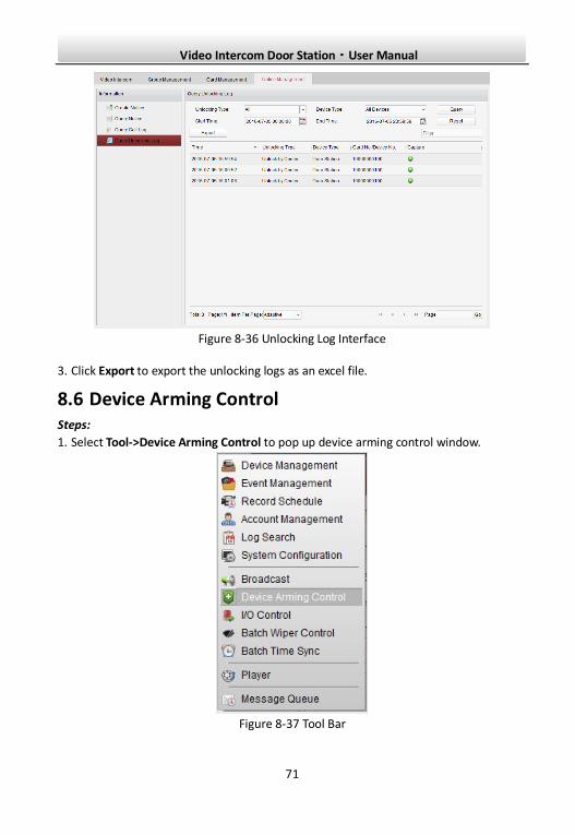
8.6 Device Arming Control Steps:
1. Select Tool->Device Arming Control to pop up device arming control window.
Figure 8-37 Tool Bar
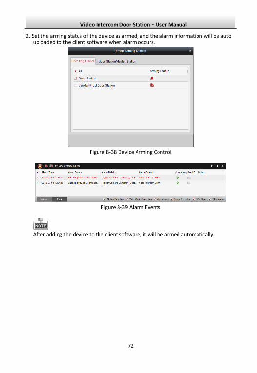
Video Intercom Door Station·User Manual
72
2. Set the arming status of the device as armed, and the alarm information will be auto uploaded to the client software when alarm occurs.
Figure 8-38 Device Arming Control
Figure 8-39 Alarm Events
After adding the device to the client software, it will be armed automatically.
Video Intercom Door Station·User Manual
73
9 Local Operation
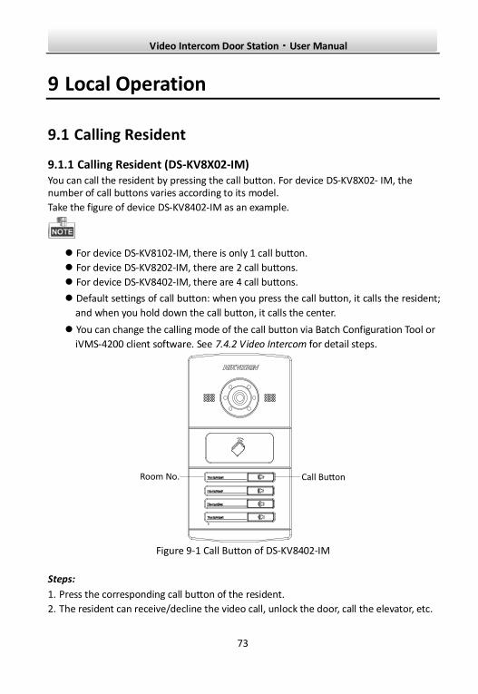
9.1 Calling Resident
9.1.1 Calling Resident (DS-KV8X02-IM) You can call the resident by pressing the call button. For device DS-KV8X02- IM, the number of call buttons varies according to its model.
Take the figure of device DS-KV8402-IM as an example.
For device DS-KV8102-IM, there is only 1 call button.
For device DS-KV8202-IM, there are 2 call buttons.
For device DS-KV8402-IM, there are 4 call buttons.
Default settings of call button: when you press the call button, it calls the resident;
and when you hold down the call button, it calls the center.
You can change the calling mode of the call button via Batch Configuration Tool or
iVMS-4200 client software. See 7.4.2 Video Intercom for detail steps.
Figure 9-1 Call Button of DS-KV8402-IM
Steps:
1. Press the corresponding call button of the resident.
2. The resident can receive/decline the video call, unlock the door, call the elevator, etc.
Video Intercom Door Station·User Manual
74
When the video intercom between you and the resident is realized, you can speak
to the resident, and the live view of door station will be displayed on the
connected indoor station.
When the door station is calling resident, the door station will detect the
brightness of video. When the brightness is lower than the expected threshold,
the supplement light will be enabled.
When the supplement light is enabled, the backlight of key will be auto-enabled,
otherwise, the door station will detect the brightness of live view and enable the
backlight of key when the brightness of live view is lower than expected threshold.
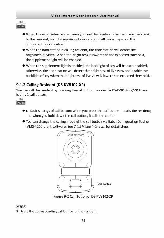
9.1.2 Calling Resident (DS-KV8102-XP) You can call the resident by pressing the call button. For device DS-KV8102-IP/VP, there is only 1 call button.
Default settings of call button: when you press the call button, it calls the resident;
and when you hold down the call button, it calls the center.
You can change the calling mode of the call button via Batch Configuration Tool or
iVMS-4200 client software. See 7.4.2 Video Intercom for detail steps.
Figure 9-2 Call Button of DS-KV8102-XP
Steps:
3. Press the corresponding call button of the resident.
Video Intercom Door Station·User Manual
75
4. The resident can receive/decline the video call, unlock the door, call the elevator, etc.
When the video intercom between you and the resident is realized, you can speak
to the resident, and the live view of door station will be displayed on the
connected indoor station.
When the door station is calling resident, the door station will detect the
brightness of video. When the brightness is lower than the expected threshold,
the supplement light will be enabled.
When the supplement light is enabled, the backlight of key will be auto-enabled,
otherwise, the door station will detect the brightness of live view and enable the
backlight of key when the brightness of live view is lower than expected threshold.
9.2 Issuing Card Purpose:
You can assign the card to the door station or doorphone by issuing cards. You can issue cards by swiping the main card with the door station, or issue the card with iVMS-4200 client software. For more information about issuing card by iVMS-4200, please refer to the user manual in the disk.
Steps:
1. Swipe the main card on the card induction area to enter the card issuing mode after hearing a voice prompt: Issuing card started.
2. Swipe the unauthorized sub card in turn on the card induction area with the beep.
3. After swiping all the sub cards, swipe the main card again, and issue each sub card successfully after hearing a voice prompt: Issuing card finished.
Only Mifare card supported, and Mifare card with non-standard shape is
recommended.
No more than 256 cards can be issued to and managed by V series door station. A
voice prompt (Card amount exceeds limit.) can be heard when the issued card
amount exceeds the upper limit.
Swipe the main card again or perform no operation for more than 10s, the device
will exit the card issuing mode automatically.
After issuing cards with client software, the local card issuing function will be
disabled.
For each main door station, at most 8 sub door stations can be added.
Video Intercom Door Station·User Manual
76
9.3 Unlocking Door Purpose:
After issuing cards, you can unlock the door by swiping the issued card.
Step:
1. Swipe the card on the card induction area.
2. Hear a voice prompt of the device: Door is open.
You cannot unlock the door by swiping the main card.
0104231070624
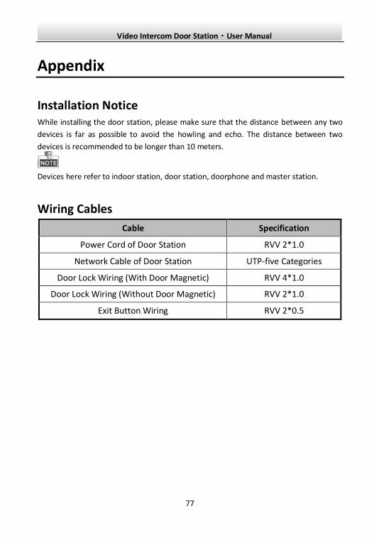
Video Intercom Door Station·User Manual
77
Appendix
Installation Notice While installing the door station, please make sure that the distance between any two
devices is far as possible to avoid the howling and echo. The distance between two
devices is recommended to be longer than 10 meters.
Devices here refer to indoor station, door station, doorphone and master station.
Wiring Cables
Cable Specification
Power Cord of Door Station RVV 2*1.0
Network Cable of Door Station UTP-five Categories
Door Lock Wiring (With Door Magnetic) RVV 4*1.0
Door Lock Wiring (Without Door Magnetic) RVV 2*1.0
Exit Button Wiring RVV 2*0.5

Video Intercom Door Station·User Manual
78