Embed Size (px)
Citation preview
2
en Specification
Video Content Description Format – Live Version 6.40
2 en | Specification Video Content Description Format
VCD Format | 6.40 | 2017.03 Specification | en Bosch Security Systems
Use of metadata generated by Bosch IVA products
Bosch products containing Intelligent Video Analytics (IVA) are licensed under the ObjectVideo,
Inc. worldwide patent portfolio. Partner-developed products that utilize metadata generated by
Bosch IVA products are not subject to any additional license fees under these patents. However,
as stated in the General Terms and Conditions of the Integration Partner Program, Bosch
assumes no liability for any patent infringement action taken by a third party against any
Integration Partner Program partners or customers. Your activity in developing products that
interface with Bosch IVA products is at your own risk and responsibility regarding fitness for use,
completeness, faultlessness, or any claims of third parties which may arise based on such further
development.
VCD Format | en 3
Bosch Security Systems Specification VCD Format | 6.40 | 2017.03
1 Table of Content
1 Table of Content .................................................................................................................................................... 3
2 Introduction ............................................................................................................................................................ 5
2.1 Purpose & scope............................................................................................................................................. 5
2.2 Definitions, acronyms & abbreviations............................................................................................................ 5
2.2.1 Definitions:................................................................................................................................................ 5
2.2.2 Abbreviations: .......................................................................................................................................... 6
2.2.3 Conventions ............................................................................................................................................. 6
2.2.3.1 Arithmetic operators .......................................................................................................................... 6
2.2.3.2 Logical operators ............................................................................................................................... 7
2.2.3.3 Relational operators .......................................................................................................................... 7
2.2.3.4 Bitwise operators ............................................................................................................................... 7
2.2.3.5 Assignment operators ........................................................................................................................ 7
2.2.3.6 Arithmetic Functions .......................................................................................................................... 8
2.2.3.7 Variables, syntax elements, and tables ............................................................................................. 8
2.2.4 Method of describing syntax in tabular form ............................................................................................ 9
3 Requirements Analysis ........................................................................................................................................ 12
3.1 Performance Analysis ................................................................................................................................... 12
4 VCD Protocol Specification ................................................................................................................................. 13
4.1 Overview ....................................................................................................................................................... 13
4.2 Syntax ........................................................................................................................................................... 14
4.3 Tag Packet .................................................................................................................................................... 16
4.3.1 Time64 ................................................................................................................................................... 16
4.3.2 Layer Info ............................................................................................................................................... 16
4.3.3 Sync Info ................................................................................................................................................ 16
4.3.4 Frame Info .............................................................................................................................................. 17
4.3.5 Alarm flags ............................................................................................................................................. 17
4.3.6 Alarm event ............................................................................................................................................ 18
4.3.7 Alarm event extension ............................................................................................................................ 19
4.3.8 Motion map............................................................................................................................................. 20
4.3.9 Object properties .................................................................................................................................... 21
4.3.9.1 Object tag packets ........................................................................................................................... 23
4.3.9.2 Huffman codes (hsvhist) .................................................................................................................. 28
4.3.9.3 Object shape polygon ...................................................................................................................... 30
4.3.10 Object extension .................................................................................................................................. 31
4.3.11 Face object properties .......................................................................................................................... 32
4 en | Specification Video Content Description Format
VCD Format | 6.40 | 2017.03 Specification | en Bosch Security Systems
4.3.12 Deleted objects list ............................................................................................................................... 33
4.3.13 Deleted face objects list ....................................................................................................................... 33
4.3.14 Event state ........................................................................................................................................... 34
4.3.15 Transparent data .................................................................................................................................. 34
4.3.16 Xml data ............................................................................................................................................... 34
4.3.17 Ignore ................................................................................................................................................... 35
4.3.18 Standard Event 1 ................................................................................................................................. 35
4.3.19 Standard Event 2 (not used) ................................................................................................................ 36
4.3.20 Object States ........................................................................................................................................ 36
4.3.21 Dome Info ............................................................................................................................................. 37
4.3.22 Counter ................................................................................................................................................. 38
4.3.23 VCA Config........................................................................................................................................... 38
4.3.24 Config Info ............................................................................................................................................ 38
4.3.25 Config Name ........................................................................................................................................ 39
4.3.26 Text Display.......................................................................................................................................... 39
4.3.27 Block Tracking Map Polar .................................................................................................................... 40
4.3.28 Crowd Density ...................................................................................................................................... 41
4.3.29 Flame Detection Info ............................................................................................................................ 42
4.3.30 Smoke Detection Info ........................................................................................................................... 43
4.3.31 Fire Alarm ............................................................................................................................................. 43
4.4 Contour Code ................................................................................................................................................ 44
5 Index of Tables .................................................................................................................................................... 45
VCD Format | en 5
Bosch Security Systems Specification VCD Format | 6.40 | 2017.03
2 Introduction
2.1 Purpose & scope
This Video Content Description (VCD) format is intended to be used for transmission and storage of
the results of a Video Content Analysis (VCA) algorithm.
The goal was to design a protocol that is
easy to generate,
easy to parse and decode,
flexible and easily extensible to add new features.
The international standards MPEG-7 / MPEG-4 that could also be used to describe metadata are
not used due to their high complexity.
A short analysis of the capabilities of this protocol can be found in chapter 3.
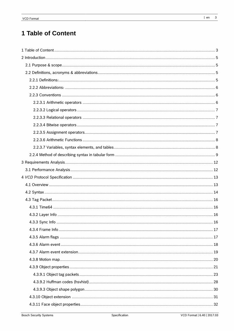
Figure 1: Flow of VCD data in a surveillance system.
The Video Content Description Format (VCD) is defined to encode the results of video content
analysis algorithms for transmission to user interfaces or to databases. VCD data can be
transmitted independently form encoded video streams and is linked to the video data via RTP
timestamps. The way the VCD data is stored in databases is beyond the scope of this format and
will strongly depend on the database architecture itself.
Major design objectives of the Bosch Video Content Description Format are simplicity, bit rate
efficiency, scalability and extendibility.
2.2 Definitions, acronyms & abbreviations
2.2.1 Definitions:
nibble: Is a sequence of 4 bits, written and read with the most significant bit on the left and the least
significant bit on the right. When represented in a sequence of
data bits, the most significant bit of a nibble is first.
object oriented VCA
Object ID’s,
bounding boxes
(position, velocity,
width & height)
event Detection
Specific Events:
loitering, left behind,...
block oriented VMD motion map
event detection
User Interface
VCD
6 en | Specification Video Content Description Format
VCD Format | 6.40 | 2017.03 Specification | en Bosch Security Systems
byte: Is a sequence of 8 bits, written and read with the most significant bit on the left and the least
significant bit on the right. When represented in a sequence of
data bits, the most significant bit of a byte is first.
byte-aligned: Is a position in a bit stream is byte-aligned when the position is an integer multiple of
8 bits from the position of the first bit in the bit stream. A bit or
byte or syntax element is said to be byte-aligned when the
position at which it appears in a bit stream is byte-aligned.
2.2.2 Abbreviations:
bps: bits per second
CIF: Common Intermediate Format Resolution: 352x288 (PAL) / 352x240 (NTSC)
fps: frames per second
kbps: kilo bits per second
LSB: least significant bit
MSB: most significant bit
msec: millisecond
RTP: Real-Time Transport Protocol
UTC: Universal Time Coordinated
VCA: Video Content Analysis
VCD: Video Content Description
VMD: Video Motion Detection
QCIF: Quarter Common Intermediate Format: Resolution: 176x144 (PAL) /
176x120 (NTSC)
2.2.3 Conventions
NOTE – The mathematical operators used in this Specification are similar to those used in the C programming language. However, integer division and arithmetic shift operations are specifically defined. Numbering and counting conventions generally begin from 0.
2.2.3.1 Arithmetic operators
The following arithmetic operators are defined as follows:
+ Addition
– Subtraction (as a two-argument operator) or negation (as a unary prefix operator)
* Multiplication
/ Integer division with truncation of the result toward zero. For example, 7/4 and –7/–4 are
truncated to 1 and –7/4 and 7/–4 are truncated to –1.
÷ Used to denote division in mathematical equations where no truncation or rounding is intended.
When order of precedence is not indicated explicitly by use of parenthesis, the following rules apply
– multiplication and division operations are considered to take place before addition and
subtraction
– multiplication and division operations in sequence are evaluated sequentially from left to
right
– addition and subtraction operations in sequence are evaluated sequentially from left to
right
VCD Format | en 7
Bosch Security Systems Specification VCD Format | 6.40 | 2017.03
2.2.3.2 Logical operators
The following logical operators are defined as follows
x && y Boolean logical “and” of x and y
x | | y Boolean logical “or” of x and y
! Boolean logical “not”
x ? y : z If x is TRUE or not equal to 0, evaluates to the value of y; otherwise, evaluates to the value of z
2.2.3.3 Relational operators
The following relational operators are defined as follows
> Greater than
≥ Greater than or equal to
< Less than
≤ Less than or equal to
== Equal to
!= Not equal to
2.2.3.4 Bitwise operators
The following bitwise operators are defined as follows
& Bitwise “and”. When operating on integer arguments, operates on a two’s complement
representation of the integer value. When operating on a binary argument that contains fewer
bits than another argument, the shorter argument is extended by adding more significant bits
equal to 0.
| Bitwise “or”. When operating on integer arguments, operates on a two’s complement
representation of the integer value. When operating on a binary argument that contains fewer
bits than another argument, the shorter argument is extended by adding more significant bits
equal to 0.
x >> y Arithmetic right shift of a two’s complement integer representation of x by y binary digits. This
function is defined only for positive integer values of y. Bits shifted into the MSBs because of the
right shift shall have a value equal to the MSB of x prior to the shift operation.
x << y Arithmetic left shift of a two’s complement integer representation of x by y binary digits. This
function is defined only for positive integer values of y. Bits shifted into the LSBs because of the
left shift have a value equal to 0.
2.2.3.5 Assignment operators
The following arithmetic operators are defined as follows
= Assignment operator.
++ Increment, i.e., x++ is equivalent to x = x + 1; when used in an array index, evaluates to the
value of the variable prior to the increment operation.
– – Decrement, i.e., x– – is equivalent to x = x – 1; when used in an array index, evaluates to the
value of the variable prior to the decrement operation.
+= Increment by amount specified, i.e., x += 3 is equivalent to x = x + 3, and x += (-3) is equivalent
to x = x + (-3).
–= Decrement by amount specified, i.e., x –= 3 is equivalent to x = x – 3, and x –= (-3) is equivalent
to x = x – (-3).
8 en | Specification Video Content Description Format
VCD Format | 6.40 | 2017.03 Specification | en Bosch Security Systems
2.2.3.6 Arithmetic Functions
The following arithmetic functions are defined as follows
abs(x) Absolute value of x. I.e., x if x≥0 and –x if x<0.
ceil(x) Smallest integer greater than x.
ld(x) Logarithm dualis. Logarithm to base 2.
2.2.3.7 Variables, syntax elements, and tables
Syntax elements in the bit stream are represented in bold type. Each syntax element is described
by its name (all lower case letters with underscore characters), its one or two syntax categories, and
one or two descriptors for its method of coded representation. The decoding process behaves
according to the value of the syntax element and to the values of previously decoded syntax
elements. When a value of a syntax element is used in the syntax tables or the text, it appears in
regular (i.e., not bold) type.
In some cases, the syntax tables may use the values of other variables derived from syntax
elements values. Such variables appear in the syntax tables, or text, named by a mixture of lower
case and upper case letter and without any underscore characters. Variables starting with an upper
case letter are derived for the decoding of the current syntax structure and all depending syntax
structures. Variables starting with an upper case letter may be used in the decoding process for
later syntax structures mentioning the originating syntax structure of the variable. Variables starting
with a lower case letter are only used within the sub clause in which they are derived.
In some cases, “mnemonic” names for syntax element values or variable values are used
interchangeably with their numerical values. Sometimes “mnemonic” names are used without any
associated numerical values. The association of values and names is specified in the text. The
names are constructed from one or more groups of letters separated by an underscore character.
Each group starts with an upper case letter and may contain more upper case letters.
Note – The syntax is described in a manner that closely follows the C-language
syntactic constructs.
Functions are described by their names, which are constructed as syntax element names, with left
and right round parentheses including zero or more variable names (for definition) or values (for
usage), separated by commas (if more than one variable).
Square parentheses are used for indexing in lists or arrays. Lists or arrays can be either syntax
elements or variables. Two-dimensional arrays are sometimes also specified using matrix notation
using subscripts for indexing.
Note – The index order for two-dimensional arrays using square brackets and
subscripts is interchanged. A sample at horizontal position x and vertical position y in a
two-dimensional sample array denoted as [x,y] would, in matrix notation, be referred to
as syx.
Binary notation is indicated by enclosing the string of bit values by single quote marks. For
example, ‘01000001’ represents an eight-bit string having only its second and its last bits equal to 1.
Hexadecimal notation, indicated by prefixing the hexadecimal number by “0x”, may be used instead
of binary notation when the number of bits is an integer multiple of 4. For example, 0x41 represents
an eight-bit string having only its second and its last bits equal to 1.
Numerical values not enclosed in single quotes and not prefixed by “0x” are decimal values.
A value equal to 0 represents a FALSE condition in a test statement. The value TRUE is
represented by any other value different than zero.
VCD Format | en 9
Bosch Security Systems Specification VCD Format | 6.40 | 2017.03
2.2.4 Method of describing syntax in tabular form
The syntax tables describe a superset of the syntax of all allowed input bit streams. Additional
constraints on the syntax may be specified in other clauses.
The following table lists examples of pseudo code used to describe the syntax. When
syntax_element appears, it specifies that a data element is read (extracted) from the bit stream and
the bit stream pointer.

10 en | Specification Video Content Description Format
VCD Format | 6.40 | 2017.03 Specification | en Bosch Security Systems
Descriptor
/* A statement can be a syntax element with an associated syntax
category and descriptor or can be an expression used to specify
conditions for the existence, type, and quantity of syntax elements, as in
the following two examples */
syntax_element u(v)
conditioning statement
/* A group of statements enclosed in curly brackets is a compound
statement and is treated functionally as a single statement. */
{
statement
statement
…
}
/* A “while” structure specifies a test of whether a condition is true, and if
true, specifies evaluation of a statement (or compound statement)
repeatedly until the condition is no longer true */
while( condition )
statement
/* A “do … while” structure specifies evaluation of a statement once,
followed by a test of whether a condition is true, and if true, specifies
repeated evaluation of the statement until the condition is no longer true
*/
do
statement
while( condition )
/* An “if … else” structure specifies a test of whether a condition is true,
and if the condition is true, specifies evaluation of a primary statement,
otherwise, specifies evaluation of an alternative statement. The “else”
part of the structure and the associated alternative statement is omitted
if no alternative statement evaluation is needed */
if( condition )
primary statement
else
alternative statement
/* A “for” structure specifies evaluation of an initial statement, followed
by a test of a condition, and if the condition is true, specifies repeated
evaluation of a primary statement followed by a subsequent statement
until the condition is no longer true. */
for( initial statement; condition; subsequent statement )
primary statement
Table 1: Syntax description in tabular form
The functions presented here are used in the syntactical description. These functions assume the
existence of a bit stream pointer with an indication of the position of the next bit to be read by the
decoding process from the bit stream.
VCD Format | en 11
Bosch Security Systems Specification VCD Format | 6.40 | 2017.03
byte_aligned( ) is specified as follows.
– If the current position in the bit stream is on a byte boundary, i.e., the next bit in the bit
stream is the first bit in a byte, the return value of byte_aligned( ) is equal to TRUE.
– Otherwise, the return value of byte_aligned( ) is equal to FALSE.
byte_align( ) advances the bit stream pointer to the next position on a byte boundary, if the current position is not on a byte boundary. Otherwise the bit stream pointer is left unchanged.
read_bits(n) reads the next n bits from the bit stream and advances the bit stream pointer by n bit
positions. When n is equal to 0, read_bits( n ) is specified to return a value equal to 0 and to not
advance the bit stream pointer.
The following descriptors specify the parsing process of each syntax element.
– f(n): fixed-pattern bit string using n bits written (from left to right) with the left bit first.
The parsing process for this descriptor is specified by the return value of the function
byte_align( ) advances the bit stream pointer to the next position on a byte boundary, if
the current position is not on a byte boundary. Otherwise the bit stream pointer is left
unchanged.
– read_bits( n ).
– u(n): unsigned integer using n bits. When n is “v” in the syntax table, the number of
bits varies in a manner dependent on the value of other syntax elements. The parsing
process for this descriptor is specified by the return value of the function byte_align( )
advances the bit stream pointer to the next position on a byte boundary, if the current
position is not on a byte boundary. Otherwise the bit stream pointer is left unchanged.
– read_bits( n ) interpreted as a binary representation of an unsigned integer with most
significant bit written first.
– s(n): signed integer using n bits. When n is “v” in the syntax table, the number of bits
varies in a manner dependent on the value of other syntax elements. The parsing
process for this descriptor is specified by the return value of the function byte_align( )
advances the bit stream pointer to the next position on a byte boundary, if the current
position is not on a byte boundary. Otherwise the bit stream pointer is left unchanged.
– read_bits( n ) interpreted as a binary representation of a signed integer with most
significant bit written first.
12 en | Specification Video Content Description Format
VCD Format | 6.40 | 2017.03 Specification | en Bosch Security Systems
3 Requirements Analysis
This protocol serves for transmission of VCD data. By adding new tags, it is easily extensible for
future requirements.
The current version includes tags for different alarm flags, a motion map, and an object properties
description. The object properties description itself is extensible by adding tags. Currently the object
description may include some alarm flags, idle time, motion vector, texture statistics, and the shape
(bounding box and contour). In addition, the shape at the time when the object was initially detected
can be transmitted afterwards, e.g., when it triggered an alarm.
3.1 Performance Analysis
In this section, we collect the bit-rate performance for some typical cases.
If only a typical motion map is transmitted approximately 1024 bits per frame are needed which
gives 25 kbps for 25 fps or 4 kbps for 4 fps.
If an object of 20 x 10 pixel size (with respect to QCIF resolution) is transmitted the contour will fill
approximately 60 * 3 bit (180 bits). The other object features will fill approximately another 100 bits.
Transmitted at 12.5 fps this gives a rate of 3.5 kbps for the transmission of features for one typical
object.
VCD Format | en 13
Bosch Security Systems Specification VCD Format | 6.40 | 2017.03
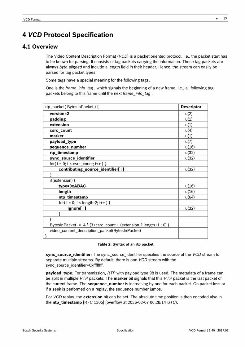
4 VCD Protocol Specification
4.1 Overview
The Video Content Description Format (VCD) is a packet oriented protocol, i.e., the packet start has
to be known for parsing. It consists of tag packets carrying the information. These tag packets are
always byte-aligned and include a length field in their header. Hence, the stream can easily be
parsed for tag packet types.
Some tags have a special meaning for the following tags.
One is the frame_info_tag , which signals the beginning of a new frame, i.e., all following tag
packets belong to this frame until the next frame_info_tag .
rtp_packet( BytesInPacket ) { Descriptor
version=2 u(2)
padding u(1)
extension u(1)
csrc_count u(4)
marker u(1)
payload_type u(7)
sequence_number u(16)
rtp_timestamp u(32)
sync_source_identifier u(32)
for( i = 0; i < csrc_count; i++ ) {
contributing_source_identifier[ i ] u(32)
}
if(extension) {
type=0xABAC u(16)
length u(16)
ntp_timestamp u(64)
for( i = 0; i < length-2; i++ ) {
ignore[ i ] u(32)
}
}
BytesInPacket -= 4 * (3+csrc_count + (extension ? length+1 : 0) )
video_content_description_packet(BytesInPacket)
}
Table 2: Syntax of an rtp packet
sync_source_identifier: The sync_source_identifier specifies the source of the VCD stream to
separate multiple streams. By default, there is one VCD stream with the
sync_source_identifier=0xffffffff.
payload_type: For transmission, RTP with payload type 98 is used. The metadata of a frame can
be split in multiple RTP packets. The marker bit signals that this RTP packet is the last packet of
the current frame. The sequence_number is increasing by one for each packet. On packet loss or
if a seek is performed on a replay, the sequence number jumps.
For VCD replay, the extension bit can be set. The absolute time position is then encoded also in
the ntp_timestamp [RFC 1305] (overflow at 2036-02-07 06:28:14 UTC).
14 en | Specification Video Content Description Format
VCD Format | 6.40 | 2017.03 Specification | en Bosch Security Systems
4.2 Syntax
The VCD format is a packet-oriented protocol, i.e., the packet boundaries have to be known for
parsing.
Each VCD packet consists of one or more tag packets. Each tag packet consists of a header with
the fields described in the following and the content of the tag packet, which is tag dependent.
video_content_description_packet( BytesInPacket ) { Descriptor
while ( BytesInPacket ) {
continuation u(1)
continued u(1)
tag u(14)
layer u(4)
length u(12)
tag_offset = (continuation && last_tag == tag) ? tag_length : 0
tag_length = tag_offset + length
for( i = tag_offset; i < tag_length; i++ ) {
tag_packet [i] u(8)
}
if( continued ) {
last_tag = tag
} else {
tag_packet(tag_length)
tag_length = 0
}
BytesInPacket -= length + 4
}
}
Table 3: Syntax of a Video Content Description (VCD) packet
The data is packetized in tag packets as described in the following.
continuation defines whether this tag packet contains the beginning of a tag information (value 0)
or is the continuation of a previous tag packet with the same tag (value 1). If continuation==0 the tag
packet can be parsed according to the corresponding sub clause. If continuation==1 the tag packet
cannot be parsed by itself but has to be appended to the last tag packet with the same tag.
continued defines whether this tag packet completes the corresponding tag information syntax
(value 0) or needs a following tag packet to be completed (value 1). If continued==0 the tag packet
fulfils completely the corresponding tag description without information missing. If continued==1 the
tag packet is not complete according to the syntax of the corresponding tag and is continued by the
following tag packet with the same tag.
If tag packets are continued, the continuation tag packet shall follow immediately.
tag specifies the kind of information in the tag packet. Possible values defined in this document are:
Tag Value Special meaning
layer_info_tag 0x0000 layer timing/ordering
frame_info_tag 0x0001 new frame
alarm_flags_tag 0x0002
motion_map_tag 0x0003
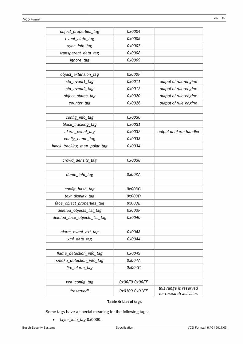
VCD Format | en 15
Bosch Security Systems Specification VCD Format | 6.40 | 2017.03
object_properties_tag 0x0004
event_state_tag 0x0005
sync_info_tag 0x0007
transparent_data_tag 0x0008
ignore_tag 0x0009
object_extension_tag 0x000F
std_event1_tag 0x0011 output of rule-engine
std_event2_tag 0x0012 output of rule-engine
object_states_tag 0x0020 output of rule-engine
counter_tag 0x0026 output of rule-engine
config_info_tag 0x0030
block_tracking_tag 0x0031
alarm_event_tag 0x0032 output of alarm handler
config_name_tag 0x0033
block_tracking_map_polar_tag 0x0034
crowd_density_tag 0x0038
dome_info_tag 0x003A
config_hash_tag 0x003C
text_display_tag 0x003D
face_object_properties_tag 0x003E
deleted_objects_list_tag 0x003F
deleted_face_objects_list_tag 0x0040
alarm_event_ext_tag 0x0043
xml_data_tag 0x0044
flame_detection_info_tag 0x0049
smoke_detection_info_tag 0x004A
fire_alarm_tag 0x004C
vca_config_tag 0x00F0-0x00FF
*reserved* 0x0100-0x01FF this range is reserved
for research activities
Table 4: List of tags
Some tags have a special meaning for the following tags:
layer_info_tag 0x0000.
16 en | Specification Video Content Description Format
VCD Format | 6.40 | 2017.03 Specification | en Bosch Security Systems
The layer_info_tag should be ignored for live VCA.
frame_info_tag 0x0001.
The frame_info_tag signals the beginning of a new frame, i.e., all following tag packets
belong to this frame until the next frame_info_tag . This sequence is mandatory.
length specifies the number of following bytes belonging to this tag packet.
tag_packet is a packet which can be parsed and decoded by tag_packet (tag_length) according to
the specification described in the appropriate sub clauses of this document.
4.3 Tag Packet
A complete tag packet can be assembled from successive packets with the same tag when
continuation and continued flags are used. All tag packets shall be byte-aligned.
4.3.1 Time64
When working with VCA data, we are not only interested in “where is something happening” or
“what is happening” but also in “when did something happen”. In order to make the time information
as much independent from the recording device as possible, we introduce a Time64 format, which is
defined as follows:
The time is expressed in multiples of 90 kHz starting from January 1st of 2000. The most significant
bits (52 to 63) of the Time64 value optionally contain the time offset between UTC and local time in
minutes. This twelve digit binary number shall be interpreted as a signed integer with valid range
-13*60 to 13*60. The following special values define that the time carries only UTC, local time or so
called linear time*:
0xFFF No local time offset available
0xFFE The time value corresponds to local time. UTC is not available.
0xFFD The time value corresponds to linear time. UTC and local time values are not
available.
0xFFC The time value corresponds to the 32 bit RTP timestamp value.†
Table 5: Time64 bitmask list
Bits 0 to 50 express the time range from 2000-01-01 00:00:00 UTC to 2792-11-07 07:25:29 UTC at
a resolution of roughly 10 microseconds. Bit 51 is reserved and shall be set to zero.
4.3.2 Layer Info
The layer_info_tag number is 0x0000.
This tag should be ignored.
4.3.3 Sync Info
sync_info() { Descriptor
rtp_time u(32)
utc_time u(64)
* Linear time is a device internal time that is guaranteed to increase monotonically even if the
devices clock is set back. Only the device knows the mapping to either UTC or local time.
† The RTP timestamp is a linear time. However, it overflows after about 13 hours.
VCD Format | en 17
Bosch Security Systems Specification VCD Format | 6.40 | 2017.03
}
Table 6: Syntax of sync info
The sync_info_tag number is 0x0007.
rtp_time is a 32-bit RTP timestamp.
utc_time is the UTC time in the Time64 format corresponding to the 32-bit RTP timestamp.
The sync info is used to relate RTP timestamps and UTC timestamps. It allows conversion of RTP
timestamps into UTC timestamps via linear interpolation.
4.3.4 Frame Info
frame_info( ) { Descriptor
frame_skip u(16)
frame_width u(16)
frame_height u(16)
}
Table 7: Syntax of frame info
The frame_info_tag number is 0x0001.
If present, a frame info tag shall always be the first tag in a VCD packet or the fist tag after a layer
tag. For the frame info tag the continuation and continued flag shall be 0, i.e., a frame info tag is
always entirely included in one packet.
frame_skip specifies how many input video frames are skipped after this one until the next VCD
packets can be expected.
frame_width and frame_height specify the frame width and height to which all following VCD
information refers.
Note – This tag can be used to transform IVA coordinates into video coordinates since
the IVA algorithm most likely uses a different resolution than the video codec.
4.3.5 Alarm flags
alarm_flags( ) { Descriptor
motion_flag u(1)
global_change_flag u(1)
signal_too_bright_flag u(1)
signal_too_dark_flag u(1)
signal_too_noisy_flag u(1)
image_too_blurry_flag u(1)
signal_loss_flag u(1)
reference_image_check_failed_flag u(1)
invalid_configuration_flag u(1)
flame_flag u(1)
smoke_flag u(1)
byte_aligned()
}
Table 8: Syntax of alarm flags
The alarm_flags_tag number is 0x0002.
The alarm flags signal various kinds of alarm events. A value of 1 means, that the alarm event has
been triggered. If an alarm event continues over several frames it has to been signaled for each
18 en | Specification Video Content Description Format
VCD Format | 6.40 | 2017.03 Specification | en Bosch Security Systems
frame in an alarm flags tag packet. This tag may be extended in future versions of this format by
appending new alarm flags.
motion_flag signals whether the motion detector has triggered alarm due to detected motion.
global_change_flag signals whether the scene has changed globally, e.g., due to camera
movement.
signal_too_bright_flag, signal_too_dark_flag, and signal_too_noisy_flag signal whether the
camera signal is too bright, too dark, or too noisy, respectively, for a reasonable analysis by the
VCA algorithm.
image_too_blurry_flag signal whether the camera signal is too blurry for a reasonable analysis by
the VCA algorithm.
signal_loss_flag signals whether the camera signal is lost.
reference_image_check_failed_flag is set if the tamper protection algorithm signals that the
camera signal whether the camera signal is lost.
invalid_configuration_flag signals that the algorithm cannot work, because the configuration is not
valid. This is for example the case if a PAL configuration is set and the connected video signal is an
NTSC signal.
flame_flag signals whether a flames was detected in the scene by the flame fire detector.
smoke_flag signals whether smoke was detected in the scene by the smoke fire detector.
Note – The motion_flag indicates motion events for the ‘Motion+’ algorithm as well as
IVA alarm events in case that the ‘IVA’ algorithm is selected on the device.
4.3.6 Alarm event
alarm_event_tag (tag_length) { Descriptor
timestamp u(32)
reserved u(3)
id u(13)
state_flag u(1)
delete_flag u(1)
state_set_flag u(1)
additional_info_flag u(1)
reserved u(4)
change_counter u(8)
name_length = (tag_length – 8)/2 > 32 ? 32 : (tag_length – 8)/2
for ( i = 0; i < name_length; i++) {
name[i] u(16)
}
Table 9: Syntax of alarm event
The alarm_event_tag number is 0x0032.
The alarm event signals the occurrence of a state change or the occurrence of an event. The states
and events are not limited to the output of the VCA algorithm including the rule engine. All states
and events signaled by the alarm_event_tag are named. Several occurrences can be collected in a
single tag.
timestamp gives the RTP timestamp of the first occurrence represented by the tag.
id specifies a unique alarm ID within the VCD stream. If the id equals zero, no ID is available.
VCD Format | en 19
Bosch Security Systems Specification VCD Format | 6.40 | 2017.03
state_flag specifies whether alarm_event is a state or an event.
delete_flag specifies whether the event is deleted and not used any more.
state_set_flag specifies whether the state has changed to active or inactive at the given timestamp.
This option is only available for states.
additional_info_flag specifies whether this entry has additional information that can be found in the
alarm_event_ext_tag.
change_counter specifies the number of occurrences, i.e. state changes or occurrences of events,
since the first occurrence at timestamp. Repeat requests for states are not counted.
name specifies the name of the event as UTF16 representation. If the name is terminated by the
end of the tag the zero termination is optional. The maximum name_length is 32 (31 UTF16
characters + zero termination).
Note – The alarm_event_tag is sent out on a regular basis with every iFrame or at
least after 10 seconds. Alarm events such as IVA alarms are conveyed in addition to
audio alarms, I/O events, motion detection, ….
4.3.7 Alarm event extension
alarm_event_ext_tag ( ) { Descriptor
reserved u(3)
Id u(13)
info_changed_flag u(1)
Reserved u(7)
additional_info_length u(16)
additional_info u(v)
Table 10: Syntax of alarm event extension
The alarm_event_ext_tag number is 0x0043.
The alarm event extension includes some additional information assigned to an alarm event.
id specifies the alarm event id to which this information belongs.
info_changed_flag signals whether the info has already been sent or has just been set.
additional_info_length is the length of the following additional information data.
The additional_info is a data segment with arbitrary user data.
Note – This extension is used to convey additional, non-standardized user data and
should be ignored in almost all cases.
20 en | Specification Video Content Description Format
VCD Format | 6.40 | 2017.03 Specification | en Bosch Security Systems
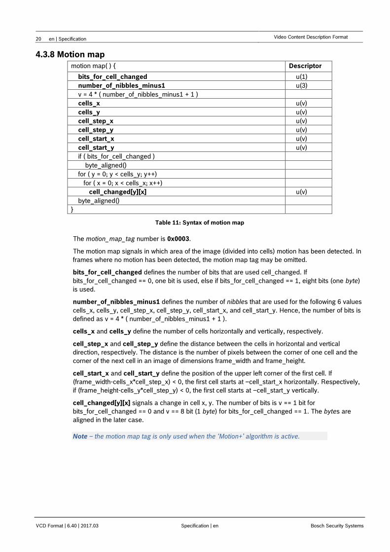
4.3.8 Motion map
motion map( ) { Descriptor
bits_for_cell_changed u(1)
number_of_nibbles_minus1 u(3)
v = 4 * ( number_of_nibbles_minus1 + 1 )
cells_x u(v)
cells_y u(v)
cell_step_x u(v)
cell_step_y u(v)
cell_start_x u(v)
cell_start_y u(v)
if ( bits_for_cell_changed )
byte_aligned()
for ( y = 0; y < cells_y; y++)
for ( x = 0; x < cells_x; x++)
cell_changed[y][x] u(v)
byte_aligned()
}
Table 11: Syntax of motion map
The motion_map_tag number is 0x0003.
The motion map signals in which area of the image (divided into cells) motion has been detected. In
frames where no motion has been detected, the motion map tag may be omitted.
bits_for_cell_changed defines the number of bits that are used cell_changed. If
bits_for_cell_changed == 0, one bit is used, else if bits_for_cell_changed == 1, eight bits (one byte)
is used.
number_of_nibbles_minus1 defines the number of nibbles that are used for the following 6 values
cells_x, cells_y, cell_step_x, cell_step_y, cell_start_x, and cell_start_y. Hence, the number of bits is
defined as v = 4 * ( number_of_nibbles_minus1 + 1 ).
cells_x and cells_y define the number of cells horizontally and vertically, respectively.
cell_step_x and cell_step_y define the distance between the cells in horizontal and vertical
direction, respectively. The distance is the number of pixels between the corner of one cell and the
corner of the next cell in an image of dimensions frame_width and frame_height.
cell_start_x and cell_start_y define the position of the upper left corner of the first cell. If
(frame_width-cells_x*cell_step_x) < 0, the first cell starts at –cell_start_x horizontally. Respectively,
if (frame_height-cells_y*cell_step_y) < 0, the first cell starts at –cell_start_y vertically.
cell_changed[y][x] signals a change in cell x, y. The number of bits is v == 1 bit for
bits_for_cell_changed == 0 and v == 8 bit (1 byte) for bits_for_cell_changed == 1. The bytes are
aligned in the later case.
Note – the motion map tag is only used when the ‘Motion+’ algorithm is active.
VCD Format | en 21
Bosch Security Systems Specification VCD Format | 6.40 | 2017.03
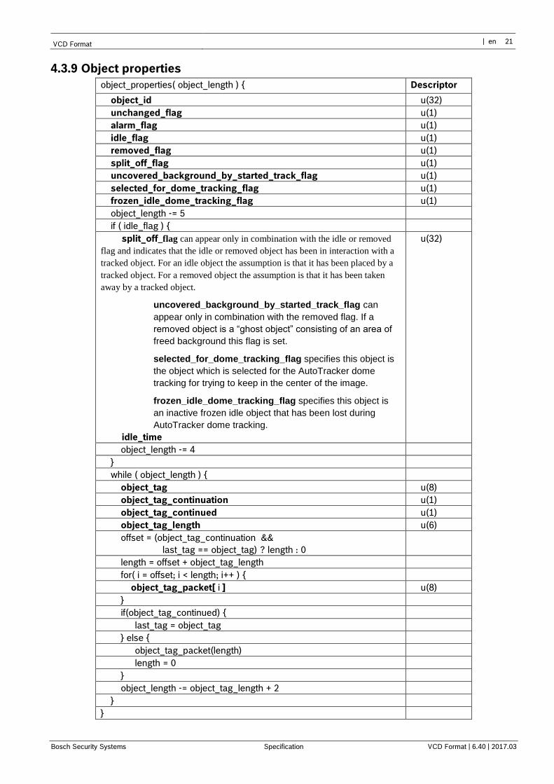
4.3.9 Object properties
object_properties( object_length ) { Descriptor
object_id u(32)
unchanged_flag u(1)
alarm_flag u(1)
idle_flag u(1)
removed_flag u(1)
split_off_flag u(1)
uncovered_background_by_started_track_flag u(1)
selected_for_dome_tracking_flag u(1)
frozen_idle_dome_tracking_flag u(1)
object_length -= 5
if ( idle_flag ) {
split_off_flag can appear only in combination with the idle or removed
flag and indicates that the idle or removed object has been in interaction with a
tracked object. For an idle object the assumption is that it has been placed by a
tracked object. For a removed object the assumption is that it has been taken
away by a tracked object.
uncovered_background_by_started_track_flag can
appear only in combination with the removed flag. If a
removed object is a “ghost object” consisting of an area of
freed background this flag is set.
selected_for_dome_tracking_flag specifies this object is
the object which is selected for the AutoTracker dome
tracking for trying to keep in the center of the image.
frozen_idle_dome_tracking_flag specifies this object is
an inactive frozen idle object that has been lost during
AutoTracker dome tracking.
idle_time
u(32)
object_length -= 4
}
while ( object_length ) {
object_tag u(8)
object_tag_continuation u(1)
object_tag_continued u(1)
object_tag_length u(6)
offset = (object_tag_continuation &&
last_tag == object_tag) ? length : 0
length = offset + object_tag_length
for( i = offset; i < length; i++ ) {
object_tag_packet[ i ] u(8)
}
if(object_tag_continued) {
last_tag = object_tag
} else {
object_tag_packet(length)
length = 0
}
object_length -= object_tag_length + 2
}
}
22 en | Specification Video Content Description Format
VCD Format | 6.40 | 2017.03 Specification | en Bosch Security Systems
Table 12: Syntax of object properties
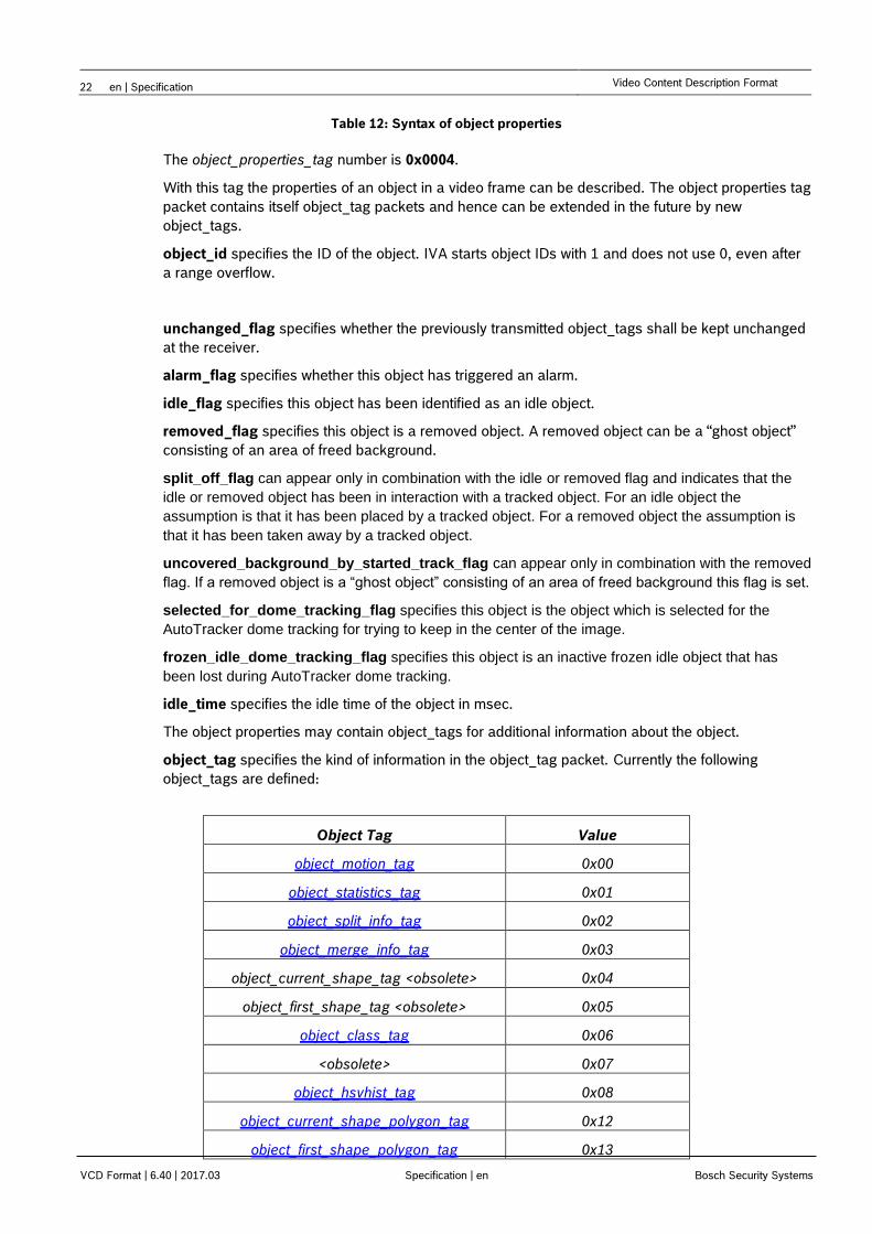
The object_properties_tag number is 0x0004.
With this tag the properties of an object in a video frame can be described. The object properties tag
packet contains itself object_tag packets and hence can be extended in the future by new
object_tags.
object_id specifies the ID of the object. IVA starts object IDs with 1 and does not use 0, even after
a range overflow.
unchanged_flag specifies whether the previously transmitted object_tags shall be kept unchanged
at the receiver.
alarm_flag specifies whether this object has triggered an alarm.
idle_flag specifies this object has been identified as an idle object.
removed_flag specifies this object is a removed object. A removed object can be a “ghost object”
consisting of an area of freed background.
split_off_flag can appear only in combination with the idle or removed flag and indicates that the
idle or removed object has been in interaction with a tracked object. For an idle object the
assumption is that it has been placed by a tracked object. For a removed object the assumption is
that it has been taken away by a tracked object.
uncovered_background_by_started_track_flag can appear only in combination with the removed
flag. If a removed object is a “ghost object” consisting of an area of freed background this flag is set.
selected_for_dome_tracking_flag specifies this object is the object which is selected for the
AutoTracker dome tracking for trying to keep in the center of the image.
frozen_idle_dome_tracking_flag specifies this object is an inactive frozen idle object that has
been lost during AutoTracker dome tracking.
idle_time specifies the idle time of the object in msec.
The object properties may contain object_tags for additional information about the object.
object_tag specifies the kind of information in the object_tag packet. Currently the following
object_tags are defined:
Object Tag Value
object_motion_tag 0x00
object_statistics_tag 0x01
object_split_info_tag 0x02
object_merge_info_tag 0x03
object_current_shape_tag <obsolete> 0x04
object_first_shape_tag <obsolete> 0x05
object_class_tag 0x06
<obsolete> 0x07
object_hsvhist_tag 0x08
object_current_shape_polygon_tag 0x12
object_first_shape_polygon_tag 0x13
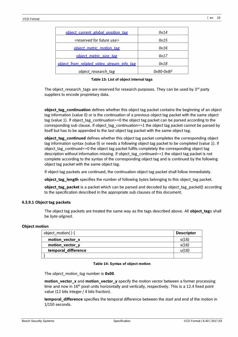
VCD Format | en 23
Bosch Security Systems Specification VCD Format | 6.40 | 2017.03
object_current_global_position_tag 0x14
<reserved for future use> 0x15
object_metric_motion_tag 0x16
object_metric_size_tag 0x17
object_from_related_video_stream_info_tag 0x18
object_research_tag 0x80-0x8F
Table 13: List of object internal tags
The object_research_tags are reserved for research purposes. They can be used by 3rd party
suppliers to encode proprietary data.
object_tag_continuation defines whether this object tag packet contains the beginning of an object
tag information (value 0) or is the continuation of a previous object tag packet with the same object
tag (value 1). If object_tag_continuation==0 the object tag packet can be parsed according to the
corresponding sub clause. If object_tag_continuation==1 the object tag packet cannot be parsed by
itself but has to be appended to the last object tag packet with the same object tag.
object_tag_continued defines whether this object tag packet completes the corresponding object
tag information syntax (value 0) or needs a following object tag packet to be completed (value 1). If
object_tag_continued==0 the object tag packet fulfils completely the corresponding object tag
description without information missing. If object_tag_continued==1 the object tag packet is not
complete according to the syntax of the corresponding object tag and is continued by the following
object tag packet with the same object tag.
If object tag packets are continued, the continuation object tag packet shall follow immediately.
object_tag_length specifies the number of following bytes belonging to this object_tag packet.
object_tag_packet is a packet which can be parsed and decoded by object_tag_packet() according
to the specification described in the appropriate sub clauses of this document.
4.3.9.1 Object tag packets
The object tag packets are treated the same way as the tags described above. All object_tags shall
be byte-aligned.
Object motion
object_motion( ) { Descriptor
motion_vector_x s(16)
motion_vector_y s(16)
temporal_difference u(16)
}
Table 14: Syntax of object motion
The object_motion_tag number is 0x00.
motion_vector_x and motion_vector_y specify the motion vector between a former processing
time and now in 16th pixel units horizontally and vertically, respectively. This is a 12.4 fixed point
value (12 bits integer / 4 bits fraction).
temporal_difference specifies the temporal difference between the start and end of the motion in
1/150 seconds.
24 en | Specification Video Content Description Format
VCD Format | 6.40 | 2017.03 Specification | en Bosch Security Systems
Object statistics
object_statistics( ) { Descriptor
texture_deviation_ratio u(16)
signal_deviation_ratio u(16)
}
Table 15: Syntax of object statistics
The object_statistics_tag number is 0x01.
texture_deviation_ratio specifies the texture deviation ratio. This is the ratio between the texture
change caused by the object and the typical texture change caused e.g. the image noise. This is a
14.2 fixed point value (14 bits integer / 2 bits fraction).
signal_deviation_ratio specifies the signal deviation ratio. This the ratio between the signal change
caused by the object and the typical signal change caused by e.g. the image noise. This is a 14.2
fixed point value (14 bits integer / 2 bits fraction).
Object split info
object_split_info( ) { Descriptor
split_object_id u(32)
}
Table 16: Syntax of object split info
The object_split_info_tag number is 0x02.
There may be multiple object_split_info_tags in one object_properties_tag.
split_object_id specify the object_id of the object from which it has been split.
Object merge info
object_merge_info( ) { Descriptor
merge_object_id u(32)
}
Table 17: Syntax of object merge info
The object_merge_info_tag number is 0x03.
There may be multiple object_merge_info_tags in one object_properties_tag.
merge_object_id specify the object_id of an object which has been merged into this one.
Object current shape polygon
object_current_shape_polygon( ) { Descriptor
object_shape_polygon( )
}
Table 18: Syntax of object current shape polygon
The object_current_shape_polygon_tag number is 0x12.
This tag contains information about the current shape and position of the object described by a
polygon as defined in sub clause 4.3.9.3. If the shape does not fit into one object tag packet it may
be continued with a following object tag packet of the same kind.
VCD Format | en 25
Bosch Security Systems Specification VCD Format | 6.40 | 2017.03
Object first shape polygon
object_first_shape_polygon( ) { Descriptor
timestamp u(32)
object_shape_polygon( )
}
Table 19: Syntax of object first shape polygon
The object_first_shape_polygon_tag number is 0x13.
This tag contains information about the shape and position of the object when it was detected for
the first time. If the shape does not fit into one object tag packet it may be continued with a following
object tag packet of the same kind.
timestamp specifies the RTP timestamp of the frame in which this object was detected for the first
time.
The parsing of the object shape described by a polygon is defined in sub clause 4.3.9.3.
Object class
object_class( ) { Descriptor
certainty u(8)
class u(8)
}
Table 20: Syntax of object class
The object_class_tag number is 0x06.
This tag contains information about the most probable class of the object.
certainty specifies the probability that the object is of the given class type. Thereby, a value of 255
encodes maximal certainty and 0 means completely uncertain.
class specifies the object’s class. The following classes are defined:
Class value
Person 1
Head 2
Car 3
Group of persons 4
Bike 5
Truck 6
Small object 7
Face 8
Table 21: Object classification
Note – Object classification works on calibrated IVA systems that have configured and
enabled enhanced tracking.
Object hsvhist
object_hsvhist( ) { Descriptor
reserved u(8)
26 en | Specification Video Content Description Format
VCD Format | 6.40 | 2017.03 Specification | en Bosch Security Systems
huffman_code_id u(8)
if(huffman_code_id>0) {
object_tag_length -= 2
for( int h = 0; h < 12; h++ ) // hue
for( int s = 0; s < 4; s++ ) // saturation
for( int v = 0; v < 4; v++ ) { // value
if(huffman_code_id==255) {
w = 8
} else {
w = lhuffman_code_id(i) // (see Huffman codes
(hsvhist)section4.3.9.2)
}
color_hist[h][s][v] u(w)
}
byte_aligned()
}
Table 22: Syntax of object_hsvhist
The object_hsvhist_tag number is 0x08.
This tag contains information about current appearance of the object. The appearance is
represented by a HSV (hue-saturation-value) histogram.
reserved is reserved for future extensions. Its current value is 0. It might be used for different color
spaces, different layouts of histograms, etc.
huffman_code_id specifies which Huffman table (see Table 27: Huffman code tables) is used for
the encoding of the color histogram. If huffman_code_id equals 0, no color histogram has been
encoded! If huffman_code_id equals 255, the color histogram is encoded in raw format, i.e. w = 8,
8 bits per bin. The preferred huffman_code_id is 1 which has an average code length of 1.9 to 2.2
per bin.
color_hist[h][s][v] is the HSV histogram accumulated over the objects’ area. The hue axis[0,360)
is partitioned into 12 equidistant intervals, (345-15) [15-45) ... [315-345), the saturation axis [0,255]
is partitioned into 4 equidistant intervals [0-64) [64-128) [128-192) [192-255] and the value axis
[0,255] is partitioned into 4 equidistant intervals [0-64) [64-128) [128-192) [192-255]. The bit length
of each entry depends on the underlying Huffman table specified by huffman_code.
The Huffman codes proposed in the next section are optimized for histograms which are first
normalized, such that all bins sum up to 1. Then, the normalized histograms are quantized to the
range 0 to 255. Although scaling the maximum bin entry to 255 improves the resolution of the
histogram, the bit rate increases by about 50%.
Object current global position
object_current_global_position( length ) { Descriptor
cartesian_position_present u(1)
geodetic_position_present u(1)
()
if( cartesian_position_present ) {
position_x s(32)
position_y s(32)
position_z s(32)
}
if( geodetic_position_present ) {
VCD Format | en 27
Bosch Security Systems Specification VCD Format | 6.40 | 2017.03
latitude s(64)
longitude s(64)
height_above_sealevel s(32)
}
}
Table 23: Syntax of object current global position
The object_current_global_position_tag number is 0x14.
This tag contains information about the current global position specified in a local cartesian and/or a
global geodetic world coordinate system.
cartesian_position_present specifies if the position in a local cartesian world coordinate system is
present.
geodetic_position_present specifies if the position in a global geodetic world coordinate system is
present.
position_x, position_y and position_z specify the position of the camera in a local world
coordinate system in units of 1/2^16 m.
latitude and longitude specify the coordinates of the object in the world coordinate system
WGS1984 in units of 2*pi/2^64. A positive latitude specifies north positions, a positive longitude
specifies east positions.
height_above_sealevel specifies the height of the object in the world coordinate system WGS
1984 in units of 1/2^16 m. This height is the height above the WGS 1984 reference ellipsoid.
Note – This tag is introduced in firmware 6.1. It is provided on calibrated IVA systems
with geolocation specification.
Object metric motion
object_metric_motion( ) { Descriptor
velocity u(16)
}
Table 24: Syntax of object metric motion.
The object_metric_motion_tag number is 0x16.
This tag contains information about the estimated current motion of the object on the ground plane
in metric units. IVA sends this info only at the tracking modes enhanced tracking or birds eye view
people counting with calibrated camera settings.
velocity specifies the speed of the object on the ground plane in units of m/s as an unsigned 10.6
fix point value.
Note – This tag is introduced in firmware 6.0. It is provided on calibrated IVA systems.
Object metric size
object_metric_size( ) { Descriptor
viewed_area u(16)
}
Table 25: Syntax of object metric size.
28 en | Specification Video Content Description Format
VCD Format | 6.40 | 2017.03 Specification | en Bosch Security Systems
The object_metric_size_tag number is 0x17.
This tag contains information about the estimated current size of the object in metric units. IVA
sends this info only at the tracking modes enhanced tracking or birds eye view people counting with
calibrated camera settings.
viewed_area specifies the estimated size of the observed object area in a plane perpendicular to
the camera view direction. The value is specified in units of 1/100 square meters.
Note – This tag is introduced in firmware 6.0. It is provided on calibrated IVA systems.
Object from related video stream info
object_from_related_video_stream_info( ) { Descriptor
video_line_number u(8)
shape_out_of_frame u(1)
video_stream_thermal u(1)
byte_align()
}
Table 26: Syntax of object from related video stream info
The object_from_related_video_stream_info_tag number is 0x18.
This tag contains additional information for an object detected in a related video channel. It is used if
the object was detected in another video stream than the video associated with the VCD stream on
devices with related image channels, e.g. MIC9000i fusion.
video_line_number specifies the video line number of the channel the object was detected in.
shape_out_of_frame specifies if the complete shape bounding box is located outside of the image
frame. This can occur when the related video channel covers a wider field of view.
video_stream_thermal specifies if the related image stream provides thermal images instead of
normal visible images.
Note – This tag is introduced in firmware 6.4. It is provided on e.g. MIC9000i fusion.
4.3.9.2 Huffman codes (hsvhist)
In this section, Huffman codes are described to encode/decode integer, non-negative values i.
Since it is assumed that the probability p(i) that value ‘i’ occurs is monotonically decreasing with
increasing value i, the Huffman code can be completely described by a list n(k) representing the
number of codes of length k. From these numbers the Huffman codes can be generated in the
following way:
First reconstruct from the list n(k) the code length l(i) of each value i. I.e. the first n(1) values
have a code length of l(i) = 1, the next n(2) values have a code length of l(i) = 2, etc.
Next, assign each value i its corresponding Huffman code h(i), such that the Huffman codes are
prefix codes, increasing, and have the correct code length.
The subsequent table contains different Huffman codes represented by their list n(k). Each Huffman
code can be referenced by a unique ID (huffman_code_id) which is an integer value between 2 and
254.
VCD Format | en 29
Bosch Security Systems Specification VCD Format | 6.40 | 2017.03
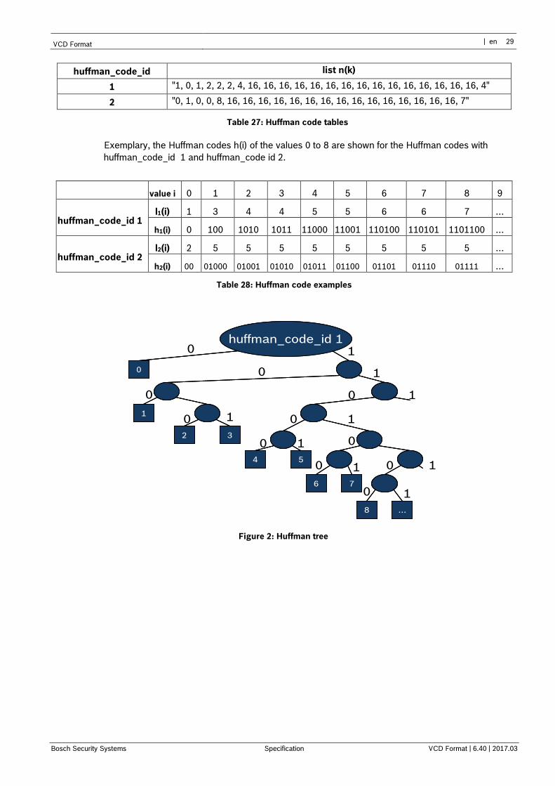
huffman_code_id list n(k)
1 "1, 0, 1, 2, 2, 2, 4, 16, 16, 16, 16, 16, 16, 16, 16, 16, 16, 16, 16, 16, 16, 16, 4"
2 "0, 1, 0, 0, 8, 16, 16, 16, 16, 16, 16, 16, 16, 16, 16, 16, 16, 16, 16, 16, 7"
Table 27: Huffman code tables
Exemplary, the Huffman codes h(i) of the values 0 to 8 are shown for the Huffman codes with
huffman_code_id 1 and huffman_code id 2.
value i 0 1 2 3 4 5 6 7 8 9
huffman_code_id 1 l1(i) 1 3 4 4 5 5 6 6 7 …
h1(i) 0 100 1010 1011 11000 11001 110100 110101 1101100 …
huffman_code_id 2 l2(i) 2 5 5 5 5 5 5 5 5 …
h2(i) 00 01000 01001 01010 01011 01100 01101 01110 01111 …
Table 28: Huffman code examples
huffman_code_id 1
0
2 3
1
6 7
8
4 5
…
huffman_code_id 1
0
2 3
1
6 7
8
4 5
…
0
2 3
1
6 7
8
4 5
…
0 1
0
0
0
0
0
0
0
0 0
0
1
1
11
1
1
1
1
Figure 2: Huffman tree
30 en | Specification Video Content Description Format
VCD Format | 6.40 | 2017.03 Specification | en Bosch Security Systems
4.3.9.3 Object shape polygon
object_shape_polygon( ) { Descriptor
number_of_nibbles_minus1_pos u(2)
number_of_nibbles_minus1_dim u(2)
x_pos s(v)
y_pos s(v)
bounding_box_width_minus1 u(w)
bounding_box_height_minus1 u(w)
x_center u(w)
y_center u(w)
x_base s(v)
y_base s(v)
x_start u(w)
y_start u(w)
object_size_minus1 u(z)
number_of_vertices_minus1 u(16)
number_of_bits_minus1_delta_pos u(4)
for ( i = 0; i < number_of_vertices_minus1; i++) {
delta_x[ i ] s(n)
delta_y[ i ] s(n)
}
byte_align( )
}
Table 29: Syntax of object shape polygon
This object shape description is based on a polygon instead of a chain for the object contour. The
polygon is not constrained to the image area.
number_of_nibbles_minus1_pos specify the number of nibbles used to encode x_pos, y_pos,
x_base and y_base. The number of bits is
v = 4 * (number_of_nibbles_minus1_pos+1).
number_of_nibbles_minus1_dim specify the number of nibbles used to encode
bounding_box_width_minus1, bounding_box_height_minus1, x_center, y_center, x_start and
y_start. The number of bits is
w = 4 * (number_of_nibbles_minus1_dim+1).
x_pos, and y_pos specify the position of the upper left corner of the bounding box of the object.
The bounding box position is not restricted to the image frame.
bounding_box_width_minus1, and bounding_box_height_minus1 specify the width and the
height of the bounding box of the object, respectively.
x_center and y_center specify the center, i.e., the position, of the object within the bounding box.
x_base and y_base specify the base point of the object. It can be outside of the bounding box.
x_start and y_start specify the starting point of the object shape polygon within the bounding box.
object_size_minus1 specifies the number of pixels that are estimated to be part of the object. It is
bounded by the bounding box dimensions. Hence, the number of bits used for object_size_size1 is
given by
z = 4 * 2 * (number_of_nibbles_minus1_dim+1).
number_of_vertices_minus1 specifies the number of vertices of the shape polygon. If this value is
0, e.g. the number of vertices is 1, there is no shape polygon available.
VCD Format | en 31
Bosch Security Systems Specification VCD Format | 6.40 | 2017.03
number_of_bits_minus1_delta_pos specify the number of bits used to encode the vertex position
difference. The number of bits is
n = number_of_bits_minus1_delta_pos+1.
delta_x and delta_y specify the position difference from the last to the current polygon vertex. At
the first time the difference is referring to the starting point.
4.3.10 Object extension
object_extension( object_length ) { Descriptor
object_id u(32)
sub_id u(8)
reserved u(8)
while ( object_length ) {
object_tag u(8)
object_tag_continuation u(1)
object_tag_continued u(1)
object_tag_length u(6)
for( i = 0; i < object_tag_length; i++ ) {
object_tag_packet[ i ] u(8)
}
object_length -= object_tag_length + 2
}
}
Table 30: Syntax of object extension
The object_extension_tag number is 0x000F.
With this tag additional object properties can easily be added to the stream afterwards. Thereby, the
object_id links the object_extension_tag to an already existing object_properties_tag. The sub_id
is introduced to enable the definition of subparts. sub_id 0 relates to the full object. The other
sub_ids can be arbitrarily used. Each subpart should include an object_class_tag in order to
specify the type of this part. The object_extension_tag can contain the same object_tag_packets
as the object_properties_tag.
object_id specifies the ID of the object the object_extension_tag belongs to.
sub_id specifies which part of the object is encoded in the object_extension_tag. Thereby, 0 refers
to the whole object.
reserved is an entry reserved for future extensions.
A more detailed description of the encoding of the object_tag_packets can be found in the Object
properties section (page 21).
32 en | Specification Video Content Description Format
VCD Format | 6.40 | 2017.03 Specification | en Bosch Security Systems
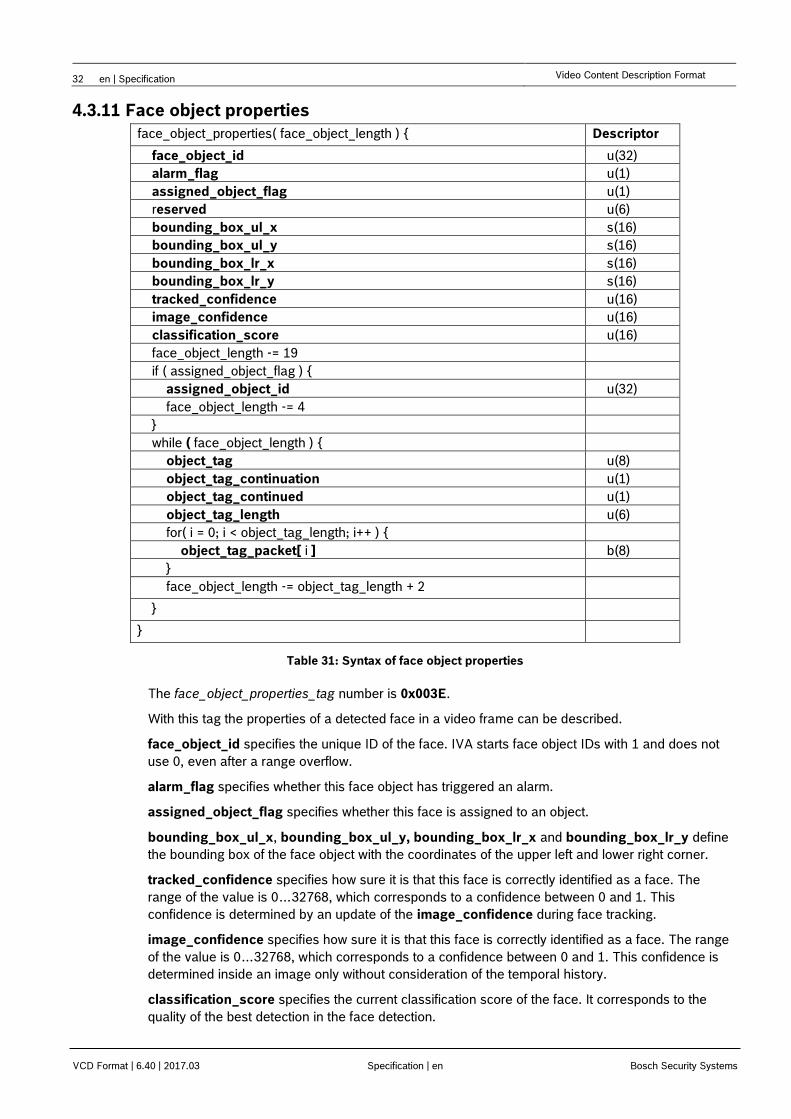
4.3.11 Face object properties
face_object_properties( face_object_length ) { Descriptor
face_object_id u(32)
alarm_flag u(1)
assigned_object_flag u(1)
reserved u(6)
bounding_box_ul_x s(16)
bounding_box_ul_y s(16)
bounding_box_lr_x s(16)
bounding_box_lr_y s(16)
tracked_confidence u(16)
image_confidence u(16)
classification_score u(16)
face_object_length -= 19
if ( assigned_object_flag ) {
assigned_object_id u(32)
face_object_length -= 4
}
while ( face_object_length ) {
object_tag u(8)
object_tag_continuation u(1)
object_tag_continued u(1)
object_tag_length u(6)
for( i = 0; i < object_tag_length; i++ ) {
object_tag_packet[ i ] b(8)
}
face_object_length -= object_tag_length + 2
}
}
Table 31: Syntax of face object properties
The face_object_properties_tag number is 0x003E.
With this tag the properties of a detected face in a video frame can be described.
face_object_id specifies the unique ID of the face. IVA starts face object IDs with 1 and does not
use 0, even after a range overflow.
alarm_flag specifies whether this face object has triggered an alarm.
assigned_object_flag specifies whether this face is assigned to an object.
bounding_box_ul_x, bounding_box_ul_y, bounding_box_lr_x and bounding_box_lr_y define
the bounding box of the face object with the coordinates of the upper left and lower right corner.
tracked_confidence specifies how sure it is that this face is correctly identified as a face. The
range of the value is 0…32768, which corresponds to a confidence between 0 and 1. This
confidence is determined by an update of the image_confidence during face tracking.
image_confidence specifies how sure it is that this face is correctly identified as a face. The range
of the value is 0…32768, which corresponds to a confidence between 0 and 1. This confidence is
determined inside an image only without consideration of the temporal history.
classification_score specifies the current classification score of the face. It corresponds to the
quality of the best detection in the face detection.
VCD Format | en 33
Bosch Security Systems Specification VCD Format | 6.40 | 2017.03
assigned_object_id specifies appear only in combination with the removed flag. If a removed
object is a “ghost object” consisting of an area of freed background this flag is set.
The face object properties may contain object tag packets for additional information about the
object. A more detailed description of the encoding of the object_tag_packets can be found in the
object properties section (page 21).
4.3.12 Deleted objects list
deleted_objects_list( length ) { Descriptor
i = 0
while ( length ) {
object_id[i] u(32)
length = lenght – 4
i++
}
}
Table 32: Syntax of deleted objects list
The deleted_objects_list_tag number is 0x003F.
With this tag information is provided about objects which aren’t tracked anymore by the VCA
algorithm. It specifies a list of all objects which are deleted inside the algorithm and won’t occur
anymore.
object_id specifies the ID of a deleted object. It corresponds to the object ID in the
object_properties_tag.
Note – This tag can be used to definitely delete the history of an object. Once an object
is marked as deleted, it is guaranteed that this object_id is no longer used. However, a
receiver is free to delete an object’s history on a timed basis after its last occurrence. A
few seconds is a reasonable number to do so.
4.3.13 Deleted face objects list
deleted_face_objects_list( length ) { Descriptor
i = 0
while ( length ) {
face_object_id[i] u(32)
length = lenght – 4
i++
}
}
Table 33: Syntax of deleted face objects list
The deleted_face_objects_list_tag number is 0x0040.
With this tag information is provided about face objects which aren’t tracked anymore by the VCA
algorithm. It specifies a list of all face objects which are deleted inside the algorithm and won’t occur
anymore.
face_object_id specifies the ID of a deleted face object. It corresponds to the face object ID in the
face_object_properties_tag.
Note – This tag can be used to definitely delete the history of a face. Once a face is
marked as deleted, it is guaranteed that this face_object_id is no longer used.
34 en | Specification Video Content Description Format
VCD Format | 6.40 | 2017.03 Specification | en Bosch Security Systems
However, a receiver is free to delete a face’s history on a timed basis after its last
occurrence. A few seconds is a reasonable number to do so.
4.3.14 Event state
event_state_tag( tag_length ) { Descriptor
for (i = 0; i < tag_length*8; i++) {
event_state_flag[i] u(1)
}
byte_aligned()
}
Table 34: Syntax of event state
The event_state_tag number is 0x0005.
The event state flags signal events that have been triggered. If an event continues over several
frames it has to been signaled for each frame in an event state tag packet.
event_state_flag signals whether the event with the event_id corresponding to ‘i’ has been
triggered by setting the corresponding bit (=1).
4.3.15 Transparent data
transparent_data_tag(tag_length) { Descriptor
timestamp u(32)
flags u(16)
for (i = 0; i < tag_length-6; i++) {
payload[i] u(8)
}
}
Table 35: Syntax of transparent data
The transparent_data_tag number is 0x0008.
It allows packing of transparent data into the VCD format.
timestamp specifies when the transparent data has been received (32-bit RTP timestamp).
flags can be used to specify the channel from which the transparent data has been received.
payload contains the transparent data.
4.3.16 Xml data
xml_data_tag( ) { Descriptor
for (i = 0; i < tag_length; i++) {
payload[i] u(8)
}
}
Table 36: Syntax of xml data
The xml_data_tag number is 0x0044.
The xml data tag has a similar meaning as the transparent data tag and will also be stored in the
same layer as the transparent data tags.
payload contains information written in a xml structure. Remind that a tag has a maximum length of
4kB.
VCD Format | en 35
Bosch Security Systems Specification VCD Format | 6.40 | 2017.03
4.3.17 Ignore
The ignore_tag number is 0x0009.
Tags with this tag number must be ignored during the processing of the VCD stream. The tag allows
removing of tags without re-encoding the stream.
4.3.18 Standard Event 1
std_event1_tag( ) { Descriptor
start_time u(32)
event_id u(32)
object_id
u(32)
}
Table 37: Syntax of standard event 1
The std_event1_tag number is 0x0011.
It represents events consisting of standard parameters. The alarm flag of the object, which has
triggered the event, must be set. In addition, the corresponding event_state_flag of the
event_state_tag must be enabled.
start_time specifies when the history of the event started (32-bit RTP timestamp).
event_id is the unique ID of the event. The upper 16bits define the event type. The lower 16bits are
used to code the rule-engine task number.
object_id is the object ID associated with the event.
Note – This tag is used to convey rule-engine events. A mapping between the rule
engine number, the associated task-type and –name can be created with the RCP+
command ‘0x0b2b’. For further details see the appropriate RCP+ documentation.
The conveyed event type is an internal event type and can’t be matched with the task
types that are received in the reply of the command ‘0xb2b’. The following table is
provided for convenience and shows the available task-type mapping through the
RCP+ command.
Type # Task-type
1 Object in field
2 Crossing line
3 Loitering
5 Condition change
6 Following route
7 Tampering
8 Removed object
9 Idle object
10 Entering field
11 Leaving field
13 Similarity search
14 Crowd detection
15 Counter
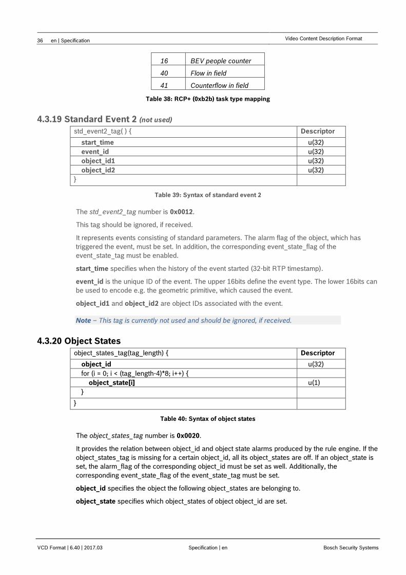
36 en | Specification Video Content Description Format
VCD Format | 6.40 | 2017.03 Specification | en Bosch Security Systems
16 BEV people counter
40 Flow in field
41 Counterflow in field
Table 38: RCP+ (0xb2b) task type mapping
4.3.19 Standard Event 2 (not used)
std_event2_tag( ) { Descriptor
start_time u(32)
event_id u(32)
object_id1 u(32)
object_id2 u(32)
}
Table 39: Syntax of standard event 2
The std_event2_tag number is 0x0012.
This tag should be ignored, if received.
It represents events consisting of standard parameters. The alarm flag of the object, which has
triggered the event, must be set. In addition, the corresponding event_state_flag of the
event_state_tag must be enabled.
start_time specifies when the history of the event started (32-bit RTP timestamp).
event_id is the unique ID of the event. The upper 16bits define the event type. The lower 16bits can
be used to encode e.g. the geometric primitive, which caused the event.
object_id1 and object_id2 are object IDs associated with the event.
Note – This tag is currently not used and should be ignored, if received.
4.3.20 Object States
object_states_tag(tag_length) { Descriptor
object_id u(32)
for (i = 0; i < (tag_length-4)*8; i++) {
object_state[i] u(1)
}
}
Table 40: Syntax of object states
The object_states_tag number is 0x0020.
It provides the relation between object_id and object state alarms produced by the rule engine. If the
object_states_tag is missing for a certain object_id, all its object_states are off. If an object_state is
set, the alarm_flag of the corresponding object_id must be set as well. Additionally, the
corresponding event_state_flag of the event_state_tag must be set.
object_id specifies the object the following object_states are belonging to.
object_state specifies which object_states of object object_id are set.
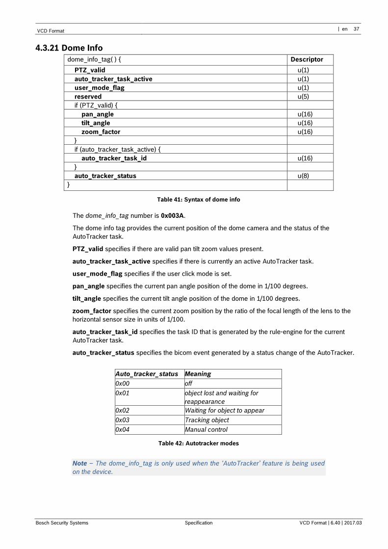
VCD Format | en 37
Bosch Security Systems Specification VCD Format | 6.40 | 2017.03
4.3.21 Dome Info
dome_info_tag( ) { Descriptor
PTZ_valid u(1)
auto_tracker_task_active u(1)
user_mode_flag u(1)
reserved u(5)
if (PTZ_valid) {
pan_angle u(16)
tilt_angle u(16)
zoom_factor u(16)
}
if (auto_tracker_task_active) {
auto_tracker_task_id u(16)
}
auto_tracker_status u(8)
}
Table 41: Syntax of dome info
The dome_info_tag number is 0x003A.
The dome info tag provides the current position of the dome camera and the status of the
AutoTracker task.
PTZ_valid specifies if there are valid pan tilt zoom values present.
auto_tracker_task_active specifies if there is currently an active AutoTracker task.
user_mode_flag specifies if the user click mode is set.
pan_angle specifies the current pan angle position of the dome in 1/100 degrees.
tilt_angle specifies the current tilt angle position of the dome in 1/100 degrees.
zoom_factor specifies the current zoom position by the ratio of the focal length of the lens to the
horizontal sensor size in units of 1/100.
auto_tracker_task_id specifies the task ID that is generated by the rule-engine for the current
AutoTracker task.
auto_tracker_status specifies the bicom event generated by a status change of the AutoTracker.
Auto_tracker_status Meaning
0x00 off
0x01 object lost and waiting for
reappearance
0x02 Waiting for object to appear
0x03 Tracking object
0x04 Manual control
Table 42: Autotracker modes
Note – The dome_info_tag is only used when the ‘AutoTracker’ feature is being used
on the device.
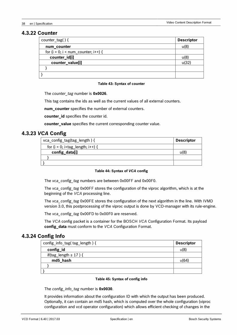
38 en | Specification Video Content Description Format
VCD Format | 6.40 | 2017.03 Specification | en Bosch Security Systems
4.3.22 Counter
counter_tag( ) { Descriptor
num_counter u(8)
for (i = 0; i < num_counter; i++) {
counter_id[i] u(8)
counter_value[i] u(32)
}
}
Table 43: Syntax of counter
The counter_tag number is 0x0026.
This tag contains the ids as well as the current values of all external counters.
num_counter specifies the number of external counters.
counter_id specifies the counter id.
counter_value specifies the current corresponding counter value.
4.3.23 VCA Config
vca_config_tag(tag_length ) { Descriptor
for (i = 0; i<tag_length; i++) {
config_data[i] u(8)
}
}
Table 44: Syntax of VCA config
The vca_config_tag numbers are between 0x00FF and 0x00F0.
The vca_config_tag 0x00FF stores the configuration of the viproc algorithm, which is at the
beginning of the VCA processing line.
The vca_config_tag 0x00FE stores the configuration of the next algorithm in the line. With IVMD
version 3.0, this postprocessing of the viproc output is done by VCD-manager with its rule-engine.
The vca_config_tag 0x00FD to 0x00F0 are reserved.
The VCA config packet is a container for the BOSCH VCA Configuration Format. Its payload
config_data must conform to the VCA Configuration Format.
4.3.24 Config Info
config_info_tag( tag_length ) { Descriptor
config_id u(8)
if(tag_length ≥ 17 ) {
md5_hash u(64)
}
}
Table 45: Syntax of config info
The config_info_tag number is 0x0030.
It provides information about the configuration ID with which the output has been produced.
Optionally, it can contain an md5 hash, which is computed over the whole configuration (viproc
configuration and vcd operator configuration) which allows efficient checking of changes in the
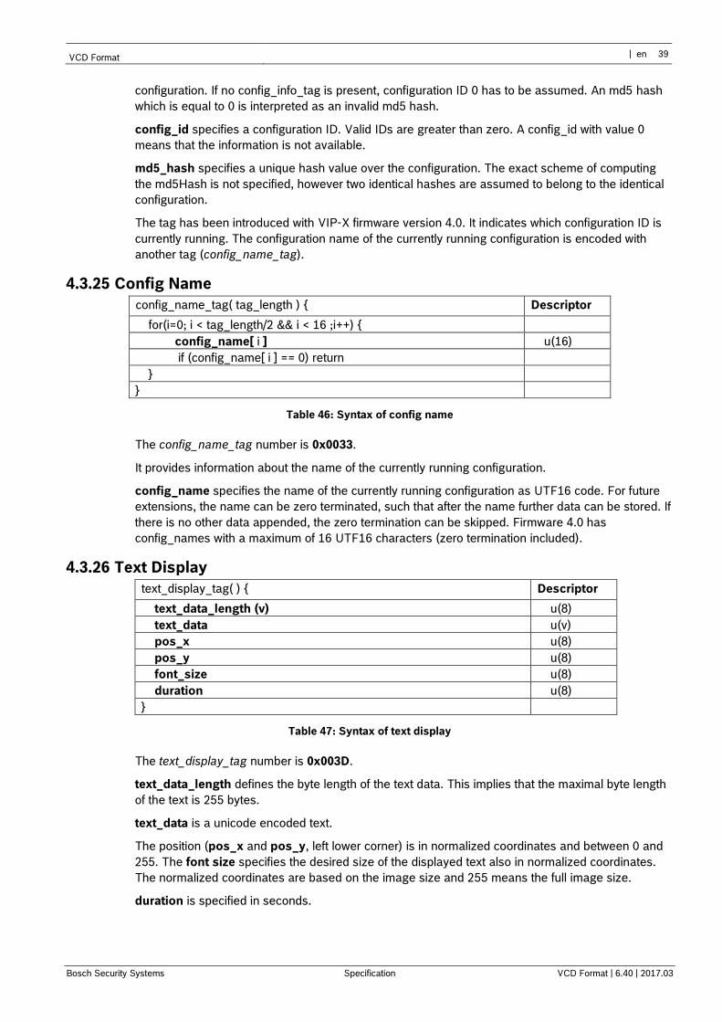
VCD Format | en 39
Bosch Security Systems Specification VCD Format | 6.40 | 2017.03
configuration. If no config_info_tag is present, configuration ID 0 has to be assumed. An md5 hash
which is equal to 0 is interpreted as an invalid md5 hash.
config_id specifies a configuration ID. Valid IDs are greater than zero. A config_id with value 0
means that the information is not available.
md5_hash specifies a unique hash value over the configuration. The exact scheme of computing
the md5Hash is not specified, however two identical hashes are assumed to belong to the identical
configuration.
The tag has been introduced with VIP-X firmware version 4.0. It indicates which configuration ID is
currently running. The configuration name of the currently running configuration is encoded with
another tag (config_name_tag).
4.3.25 Config Name
config_name_tag( tag_length ) { Descriptor
for(i=0; i < tag_length/2 && i < 16 ;i++) {
config_name[ i ] u(16)
if (config_name[ i ] == 0) return
}
}
Table 46: Syntax of config name
The config_name_tag number is 0x0033.
It provides information about the name of the currently running configuration.
config_name specifies the name of the currently running configuration as UTF16 code. For future
extensions, the name can be zero terminated, such that after the name further data can be stored. If
there is no other data appended, the zero termination can be skipped. Firmware 4.0 has
config_names with a maximum of 16 UTF16 characters (zero termination included).
4.3.26 Text Display
text_display_tag( ) { Descriptor
text_data_length (v) u(8)
text_data u(v)
pos_x u(8)
pos_y u(8)
font_size u(8)
duration u(8)
}
Table 47: Syntax of text display
The text_display_tag number is 0x003D.
text_data_length defines the byte length of the text data. This implies that the maximal byte length
of the text is 255 bytes.
text_data is a unicode encoded text.
The position (pos_x and pos_y, left lower corner) is in normalized coordinates and between 0 and
255. The font size specifies the desired size of the displayed text also in normalized coordinates.
The normalized coordinates are based on the image size and 255 means the full image size.
duration is specified in seconds.
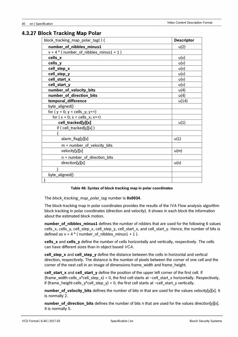
40 en | Specification Video Content Description Format
VCD Format | 6.40 | 2017.03 Specification | en Bosch Security Systems
4.3.27 Block Tracking Map Polar
block_tracking_map_polar_tag( ) { Descriptor
number_of_nibbles_minus1 u(2)
v = 4 * ( number_of_nibbles_minus1 + 1 )
cells_x u(v)
cells_y u(v)
cell_step_x u(v)
cell_step_y u(v)
cell_start_x u(v)
cell_start_y u(v)
number_of_velocity_bits u(4)
number_of_direction_bits u(4)
temporal_difference u(14)
byte_aligned()
for ( y = 0; y < cells_y; y++)
for ( x = 0; x < cells_x; x++)
cell_tracked[y][x] u(1)
if ( cell_tracked[y][x] )
{
alarm_flag[y][x] u(1)
m = number_of_velocity_bits
velocity[y][x] u(m)
n = number_of_direction_bits
direction[y][x] u(n)
}
byte_aligned()
}
Table 48: Syntax of block tracking map in polar coordinates
The block_tracking_map_polar_tag number is 0x0034.
The block-tracking map in polar coordinates provides the results of the IVA Flow analysis algorithm
block tracking in polar coordinates (direction and velocity). It shows in each block the information
about the estimated block motion.
number_of_nibbles_minus1 defines the number of nibbles that are used for the following 6 values
cells_x, cells_y, cell_step_x, cell_step_y, cell_start_x, and cell_start_y. Hence, the number of bits is
defined as v = 4 * ( number_of_nibbles_minus1 + 1 ).
cells_x and cells_y define the number of cells horizontally and vertically, respectively. The cells
can have different sizes than in object based VCA.
cell_step_x and cell_step_y define the distance between the cells in horizontal and vertical
direction, respectively. The distance is the number of pixels between the corner of one cell and the
corner of the next cell in an image of dimensions frame_width and frame_height.
cell_start_x and cell_start_y define the position of the upper left corner of the first cell. If
(frame_width-cells_x*cell_step_x) < 0, the first cell starts at –cell_start_x horizontally. Respectively,
if (frame_height-cells_y*cell_step_y) < 0, the first cell starts at –cell_start_y vertically.
number_of_velocity_bits defines the number of bits m that are used for the values velocity[y][x]. It
is normally 2.
number_of_direction_bits defines the number of bits n that are used for the values direction[y][x].
It is normally 5.
VCD Format | en 41
Bosch Security Systems Specification VCD Format | 6.40 | 2017.03
temporal_difference specifies the temporal difference between the start and end of the motion in
1/150 seconds.
cell_tracked[y][x] signals a successful block track in cell x, y.
alarm_flag[y][x] is set 1 when cell x, y caused an alarm, otherwise 0.
velocity[y][x] and direction[y][x] specify the velocity of the motion vector between the start of the
block track and now in polar coordinates. The velocity can take values quantized in m bits.
Normally 2 bits are used and show values 0, 1, 2, and 3 corresponding to no motion vector, slow
speed, medium speed, and fast speed, respectively. In this case of m=2 the velocity ranges are
defined as following: slow speed is greater than zero pixel/s, medium is greater than 18.75 pixel/s
and fast is greater than 31.25 pixel/s. These thresholds correspond to a magnitude of the motion
vector of 12/8 pixel and 20/8 pixel, if the temporal difference is 12/150 s as at a frame rate of
12.5 fps. The direction is quantized to 2^n linear spaced values. Normally 5 bits are used resulting
in values 0 ... 31. Direction zero means a vector in the direction of positive x values and the rotation
is mathematically positive in the Cartesian coordinate system, i.e. clockwise as shown in the next
figure.
Figure 3: Direction of velocity
4.3.28 Crowd Density
crowd_density_tag( ) { Descriptor
number_of_image_areas u(8)
for (i = 0; i < number_of_image_areas; i++) {
density_estimated[i] u(1)
if (density_estimated[i] ) {
density[i] u(7)
}
}
byte_aligned()
}
Table 49: Syntax of crowd density
The crowd_density_tag number is 0x0038.
The crowd density tag provides the results of the crowd density estimation.
number_of_image_areas specifies the number of image areas configured in the crowd density
estimation settings. In IVA4.5 the number of image areas is limited to 3.
density_estimated[i] specifies if a crowd density is estimated for the image area i.
density[i] specifies the estimated percentage of the crowd density in image area i. The value can
be in the range from 0 to 100.
99% 0
2n-1
1x
y
42 en | Specification Video Content Description Format
VCD Format | 6.40 | 2017.03 Specification | en Bosch Security Systems
4.3.29 Flame Detection Info
flame_detection_info(tag_length ) { Descriptor
number_of_alarm_areas u(8)
tag_length-=1
for ( i = 0; i < number_of_alarm_areas; i++) {
alarm_area_pos_x[i] u(16)
alarm_area_pos_y[i] u(16)
alarm_area_dim_x[i] u(16)
alarm_area_dim_y[i] u(16)
tag_length-=8
}
for ( i = 0; i < tag_length; i++) {
reserved u(8)
tag_length-=1
}
}
Table 50: Syntax of flame detection info
The flame_detection_info_tag number is 0x0049.
The flame detection info provides information of the results of the last run of the flame detection in
firmware 6.18. As the flame detection runs asynchronously with a much slower frame rate than the
main VCA algorithms, the flame detection info tag is only sent at a recent new run of the flame
detector. The current flame alarm status is provided in the alarm_flags tag.
number_of_alarm_areas specifies the number of all areas with a detected flame. If it is greater
than 0, a flame alarm is detected. Its maximum value is 255.
alarm_area_pos_x[i], alarm_area_pos_y[i], alarm_area_dim_x[i] and alarm_area_dim_y[i]
specify the position and size of the bounding box of each of the alarm areas.
Note – This tag is introduced in firmware 6.3. The flame_detection_info_tag is sent
only every 4s.
VCD Format | en 43
Bosch Security Systems Specification VCD Format | 6.40 | 2017.03
4.3.30 Smoke Detection Info
smoke_detection_info(tag_length ) { Descriptor
number_of_alarm_areas u(8)
tag_length-=1
for ( i = 0; i < number_of_alarm_areas; i++) {
alarm_area_pos_x[i] u(16)
alarm_area_pos_y[i] u(16)
alarm_area_dim_x[i] u(16)
alarm_area_dim_y[i] u(16)
tag_length-=8
}
for ( i = 0; i < tag_length; i++) {
reserved u(8)
tag_length-=1
}
}
Table 51: Syntax of smoke detection info
The smoke_detection_info_tag number is 0x004A.
The smoke detection info provides information of the results of the last run of the smoke detection in
firmware 6.18. The smoke detection info tag is sent every VCA frame if smoke detection is
activated. The current smoke alarm status is provided in the alarm_flags tag.
number_of_alarm_areas specifies the number of all areas with detected smoke. If it is greater than
0, a smoke alarm is detected. Its maximum value is 255.
Note – This tag is introduced in firmware 6.3.
4.3.31 Fire Alarm
fire_alarm( ) { Descriptor
flame_alarm_flag u(1)
smoke_alarm_flag u(1)
fire_trouble_illumination_out_of_range_flag u(1)
general_fire_trouble_flag u(1)
byte_align()
}
Table 52: Syntax of fire alarm
The fire_alarm_tag number is 0x004C.
The fire alarm signals various kinds of fire alarm and trouble events in firmware 6.40. A value of 1
means that the alarm event has been triggered. If a fire alarm event continues over several frames,
it has to be signalled for each frame in a fire alarm tag packet. The first two flags are contained also
in the tag alarm_flags.
flame_alarm_flag signals whether flames were detected in the scene by the flame fire detector.
44 en | Specification Video Content Description Format
VCD Format | 6.40 | 2017.03 Specification | en Bosch Security Systems
smoke_alarm_flag signals whether smoke was detected in the scene by the smoke fire detector.
fire_trouble_illumination_out_of_range_flag signals whether the scene illumination is out of
range for the analysis by the fire detector.
general_fire_trouble_flag signals general trouble of the fire detector.
Note – This tag is introduced in firmware 6.4.
4.4 Contour Code
The contour is described by a chain code. The contour of the object is coded in steps in the model
of 8-neighborhood.
Possible steps are:
code dx dy direction
0 +1 0 right
1 +1 -1 right-up
2 0 -1 up
3 -1 -1 left-up
4 -1 0 left
5 -1 +1 left-down
6 0 +1 down
7 +1 +1 right-down
Table 53: Chain code for contour coding
VCD Format | en 45
Bosch Security Systems Specification VCD Format | 6.40 | 2017.03
5 Index of Tables
Table 1: Syntax description in tabular form ............................................................................................................ 10
Table 2: Syntax of an rtp packet ............................................................................................................................. 13
Table 3: Syntax of a Video Content Description (VCD) packet .............................................................................. 14
Table 4: List of tags ................................................................................................................................................ 15
Table 5: Time64 bitmask list ................................................................................................................................... 16
Table 6: Syntax of sync info ................................................................................................................................... 17
Table 7: Syntax of frame info ................................................................................................................................. 17
Table 8: Syntax of alarm flags ................................................................................................................................ 17
Table 9: Syntax of alarm event ............................................................................................................................... 18
Table 10: Syntax of alarm event extension ............................................................................................................ 19
Table 11: Syntax of motion map ............................................................................................................................. 20
Table 12: Syntax of object properties ..................................................................................................................... 22
Table 13: List of object internal tags ....................................................................................................................... 23
Table 14: Syntax of object motion .......................................................................................................................... 23
Table 15: Syntax of object statistics ....................................................................................................................... 24
Table 16: Syntax of object split info ........................................................................................................................ 24
Table 17: Syntax of object merge info .................................................................................................................... 24
Table 18: Syntax of object current shape .......................................................... Fehler! Textmarke nicht definiert.
Table 19: Syntax of object first shape ............................................................... Fehler! Textmarke nicht definiert.
Table 20: Syntax of object current shape polygon ................................................................................................. 24
Table 21: Syntax of object first shape polygon ...................................................................................................... 25
Table 22: Syntax of object class ............................................................................................................................. 25
Table 23: Object classification ................................................................................................................................ 25
Table 24: Syntax of object_hsvhist ......................................................................................................................... 26
Table 25: Syntax of object current global position ................................................................................................. 27
Table 26: Syntax of object metric motion. .............................................................................................................. 27
Table 27: Syntax of object metric size. ................................................................................................................... 27
Table 28: Syntax of object from related video stream info ..................................................................................... 28
Table 29: Huffman code tables .............................................................................................................................. 29
Table 29: Huffman code examples ......................................................................................................................... 29
Table 30: Syntax of object shape ...................................................................... Fehler! Textmarke nicht definiert.
Table 31: Syntax of object shape polygon ............................................................................................................. 30
Table 32: Syntax of object extension ..................................................................................................................... 31
Table 33: Syntax of face object properties ............................................................................................................. 32
Table 34: Syntax of deleted objects list .................................................................................................................. 33
Table 35: Syntax of deleted face objects list .......................................................................................................... 33
46 en | Specification Video Content Description Format
VCD Format | 6.40 | 2017.03 Specification | en Bosch Security Systems
Table 36: Syntax of event state .............................................................................................................................. 34
Table 37: Syntax of transparent data ..................................................................................................................... 34
Table 38: Syntax of xml data .................................................................................................................................. 34
Table 39: Syntax of standard event 1 ..................................................................................................................... 35
Table 40: RCP+ (0xb2b) task type mapping .......................................................................................................... 36
Table 41: Syntax of standard event 2 ..................................................................................................................... 36
Table 42: Syntax of object states ........................................................................................................................... 36
Table 43: Syntax of dome info ................................................................................................................................ 37
Table 44: Autotracker modes ................................................................................................................................. 37
Table 45: Syntax of counter ................................................................................................................................... 38
Table 46: Syntax of VCA config ............................................................................................................................. 38
Table 47: Syntax of config info ............................................................................................................................... 38
Table 48: Syntax of config name ............................................................................................................................ 39
Table 49: Syntax of text display ............................................................................................................................. 39
Table 50: Syntax of block tracking map in polar coordinates ................................................................................. 40
Table 51: Syntax of crowd density ......................................................................................................................... 41
Table 52: Syntax of flame detection info ................................................................................................................ 42
Table 54: Syntax of smoke detection info .............................................................................................................. 43
Table 60: Syntax of fire alarm ................................................................................................................................ 43
Table 54: Chain code for contour coding ............................................................................................................... 44

Bosch Sicherheitssysteme GmbH
Werner-von-Siemens-Ring 10
85630 Grasbrunn
Germany
www.boschsecurity.com
COPYRIGHT: © 2016 Bosch Security Systems B.V.
The reproduction, distribution and utilization of this file as well as the communication of its contents to others without express authorization is prohibited.
Offenders will be held liable for the payment of damages. All rights reserved in the event of the grant of a patent, utility model or design.


![Portfolio i referencje krakweb [2017.03]](https://img.pdfslide.us/doc/110x75/5a66ff8c7f8b9ae45c8b4965/portfolio-i-referencje-krakweb-201703.jpg)